EP4516538A1 - Integrated module for vehicle thermal management system, vehicle thermal management system, and vehicle - Google Patents
Integrated module for vehicle thermal management system, vehicle thermal management system, and vehicle Download PDFInfo
- Publication number
- EP4516538A1 EP4516538A1 EP23795016.7A EP23795016A EP4516538A1 EP 4516538 A1 EP4516538 A1 EP 4516538A1 EP 23795016 A EP23795016 A EP 23795016A EP 4516538 A1 EP4516538 A1 EP 4516538A1
- Authority
- EP
- European Patent Office
- Prior art keywords
- interface
- heat exchanger
- battery
- refrigerant
- flow channel
- Prior art date
- Legal status (The legal status is an assumption and is not a legal conclusion. Google has not performed a legal analysis and makes no representation as to the accuracy of the status listed.)
- Pending
Links
Images


Classifications
-
- B—PERFORMING OPERATIONS; TRANSPORTING
- B60—VEHICLES IN GENERAL
- B60H—ARRANGEMENTS OF HEATING, COOLING, VENTILATING OR OTHER AIR-TREATING DEVICES SPECIALLY ADAPTED FOR PASSENGER OR GOODS SPACES OF VEHICLES
- B60H1/00—Heating, cooling or ventilating devices
- B60H1/00007—Combined heating, ventilating, or cooling devices
-
- B—PERFORMING OPERATIONS; TRANSPORTING
- B60—VEHICLES IN GENERAL
- B60H—ARRANGEMENTS OF HEATING, COOLING, VENTILATING OR OTHER AIR-TREATING DEVICES SPECIALLY ADAPTED FOR PASSENGER OR GOODS SPACES OF VEHICLES
- B60H1/00—Heating, cooling or ventilating devices
- B60H1/00321—Heat exchangers for air-conditioning devices
-
- B—PERFORMING OPERATIONS; TRANSPORTING
- B60—VEHICLES IN GENERAL
- B60H—ARRANGEMENTS OF HEATING, COOLING, VENTILATING OR OTHER AIR-TREATING DEVICES SPECIALLY ADAPTED FOR PASSENGER OR GOODS SPACES OF VEHICLES
- B60H1/00—Heating, cooling or ventilating devices
- B60H1/00321—Heat exchangers for air-conditioning devices
- B60H1/00342—Heat exchangers for air-conditioning devices of the liquid-liquid type
-
- B—PERFORMING OPERATIONS; TRANSPORTING
- B60—VEHICLES IN GENERAL
- B60H—ARRANGEMENTS OF HEATING, COOLING, VENTILATING OR OTHER AIR-TREATING DEVICES SPECIALLY ADAPTED FOR PASSENGER OR GOODS SPACES OF VEHICLES
- B60H1/00—Heating, cooling or ventilating devices
- B60H1/00485—Valves for air-conditioning devices, e.g. thermostatic valves
-
- B—PERFORMING OPERATIONS; TRANSPORTING
- B60—VEHICLES IN GENERAL
- B60H—ARRANGEMENTS OF HEATING, COOLING, VENTILATING OR OTHER AIR-TREATING DEVICES SPECIALLY ADAPTED FOR PASSENGER OR GOODS SPACES OF VEHICLES
- B60H1/00—Heating, cooling or ventilating devices
- B60H1/00507—Details, e.g. mounting arrangements, desaeration devices
- B60H1/00557—Details of ducts or cables
- B60H1/00571—Details of ducts or cables of liquid ducts, e.g. for coolant liquids or refrigerants
-
- B—PERFORMING OPERATIONS; TRANSPORTING
- B60—VEHICLES IN GENERAL
- B60H—ARRANGEMENTS OF HEATING, COOLING, VENTILATING OR OTHER AIR-TREATING DEVICES SPECIALLY ADAPTED FOR PASSENGER OR GOODS SPACES OF VEHICLES
- B60H1/00—Heating, cooling or ventilating devices
- B60H1/02—Heating, cooling or ventilating devices the heat being derived from the propulsion plant
- B60H1/04—Heating, cooling or ventilating devices the heat being derived from the propulsion plant from cooling liquid of the plant
- B60H1/06—Heating, cooling or ventilating devices the heat being derived from the propulsion plant from cooling liquid of the plant directly from main radiator
-
- B—PERFORMING OPERATIONS; TRANSPORTING
- B60—VEHICLES IN GENERAL
- B60H—ARRANGEMENTS OF HEATING, COOLING, VENTILATING OR OTHER AIR-TREATING DEVICES SPECIALLY ADAPTED FOR PASSENGER OR GOODS SPACES OF VEHICLES
- B60H1/00—Heating, cooling or ventilating devices
- B60H1/02—Heating, cooling or ventilating devices the heat being derived from the propulsion plant
- B60H1/14—Heating, cooling or ventilating devices the heat being derived from the propulsion plant other than from cooling liquid of the plant
- B60H1/143—Heating, cooling or ventilating devices the heat being derived from the propulsion plant other than from cooling liquid of the plant the heat being derived from cooling an electric component, e.g. electric motors, electric circuits, fuel cells or batteries
-
- B—PERFORMING OPERATIONS; TRANSPORTING
- B60—VEHICLES IN GENERAL
- B60H—ARRANGEMENTS OF HEATING, COOLING, VENTILATING OR OTHER AIR-TREATING DEVICES SPECIALLY ADAPTED FOR PASSENGER OR GOODS SPACES OF VEHICLES
- B60H1/00—Heating, cooling or ventilating devices
- B60H1/22—Heating, cooling or ventilating devices the heat source being other than the propulsion plant
- B60H1/2215—Heating, cooling or ventilating devices the heat source being other than the propulsion plant the heat being derived from electric heaters
-
- B—PERFORMING OPERATIONS; TRANSPORTING
- B60—VEHICLES IN GENERAL
- B60H—ARRANGEMENTS OF HEATING, COOLING, VENTILATING OR OTHER AIR-TREATING DEVICES SPECIALLY ADAPTED FOR PASSENGER OR GOODS SPACES OF VEHICLES
- B60H1/00—Heating, cooling or ventilating devices
- B60H1/32—Cooling devices
- B60H1/3204—Cooling devices using compression
- B60H1/3227—Cooling devices using compression characterised by the arrangement or the type of heat exchanger, e.g. condenser, evaporator
-
- B—PERFORMING OPERATIONS; TRANSPORTING
- B60—VEHICLES IN GENERAL
- B60H—ARRANGEMENTS OF HEATING, COOLING, VENTILATING OR OTHER AIR-TREATING DEVICES SPECIALLY ADAPTED FOR PASSENGER OR GOODS SPACES OF VEHICLES
- B60H1/00—Heating, cooling or ventilating devices
- B60H1/32—Cooling devices
- B60H1/3204—Cooling devices using compression
- B60H1/3229—Cooling devices using compression characterised by constructional features, e.g. housings, mountings, conversion systems
-
- B—PERFORMING OPERATIONS; TRANSPORTING
- B60—VEHICLES IN GENERAL
- B60H—ARRANGEMENTS OF HEATING, COOLING, VENTILATING OR OTHER AIR-TREATING DEVICES SPECIALLY ADAPTED FOR PASSENGER OR GOODS SPACES OF VEHICLES
- B60H1/00—Heating, cooling or ventilating devices
- B60H1/32—Cooling devices
- B60H1/3204—Cooling devices using compression
- B60H1/323—Cooling devices using compression characterised by comprising auxiliary or multiple systems, e.g. plurality of evaporators, or by involving auxiliary cooling devices
-
- H—ELECTRICITY
- H01—ELECTRIC ELEMENTS
- H01M—PROCESSES OR MEANS, e.g. BATTERIES, FOR THE DIRECT CONVERSION OF CHEMICAL ENERGY INTO ELECTRICAL ENERGY
- H01M10/00—Secondary cells; Manufacture thereof
- H01M10/60—Heating or cooling; Temperature control
- H01M10/61—Types of temperature control
- H01M10/613—Cooling or keeping cold
-
- H—ELECTRICITY
- H01—ELECTRIC ELEMENTS
- H01M—PROCESSES OR MEANS, e.g. BATTERIES, FOR THE DIRECT CONVERSION OF CHEMICAL ENERGY INTO ELECTRICAL ENERGY
- H01M10/00—Secondary cells; Manufacture thereof
- H01M10/60—Heating or cooling; Temperature control
- H01M10/61—Types of temperature control
- H01M10/615—Heating or keeping warm
-
- H—ELECTRICITY
- H01—ELECTRIC ELEMENTS
- H01M—PROCESSES OR MEANS, e.g. BATTERIES, FOR THE DIRECT CONVERSION OF CHEMICAL ENERGY INTO ELECTRICAL ENERGY
- H01M10/00—Secondary cells; Manufacture thereof
- H01M10/60—Heating or cooling; Temperature control
- H01M10/62—Heating or cooling; Temperature control specially adapted for specific applications
- H01M10/625—Vehicles
-
- H—ELECTRICITY
- H01—ELECTRIC ELEMENTS
- H01M—PROCESSES OR MEANS, e.g. BATTERIES, FOR THE DIRECT CONVERSION OF CHEMICAL ENERGY INTO ELECTRICAL ENERGY
- H01M10/00—Secondary cells; Manufacture thereof
- H01M10/60—Heating or cooling; Temperature control
- H01M10/66—Heat-exchange relationships between the cells and other systems, e.g. central heating systems or fuel cells
- H01M10/663—Heat-exchange relationships between the cells and other systems, e.g. central heating systems or fuel cells the system being an air-conditioner or an engine
-
- B—PERFORMING OPERATIONS; TRANSPORTING
- B60—VEHICLES IN GENERAL
- B60H—ARRANGEMENTS OF HEATING, COOLING, VENTILATING OR OTHER AIR-TREATING DEVICES SPECIALLY ADAPTED FOR PASSENGER OR GOODS SPACES OF VEHICLES
- B60H1/00—Heating, cooling or ventilating devices
- B60H1/00271—HVAC devices specially adapted for particular vehicle parts or components and being connected to the vehicle HVAC unit
- B60H1/00278—HVAC devices specially adapted for particular vehicle parts or components and being connected to the vehicle HVAC unit for the battery
-
- B—PERFORMING OPERATIONS; TRANSPORTING
- B60—VEHICLES IN GENERAL
- B60H—ARRANGEMENTS OF HEATING, COOLING, VENTILATING OR OTHER AIR-TREATING DEVICES SPECIALLY ADAPTED FOR PASSENGER OR GOODS SPACES OF VEHICLES
- B60H1/00—Heating, cooling or ventilating devices
- B60H1/00271—HVAC devices specially adapted for particular vehicle parts or components and being connected to the vehicle HVAC unit
- B60H2001/00307—Component temperature regulation using a liquid flow
Definitions
- An objective of the present disclosure is to provide an integrated module for a vehicle thermal management system, a vehicle thermal management system, and a vehicle.
- the integrated module can simplify a structure of a thermal management system of a vehicle, reduce a space occupied by the thermal management system, and reduce costs and assembly difficulty; and can improve a utilization rate of heat energy in the thermal management system, thereby achieving energy saving.
- At least one flow channel is provided in the body.
- a battery heat exchanger is configured to exchange heat with a battery coolant circuit in which a battery is located, and the battery coolant circuit is configured to exchange heat with an engine coolant circuit in which an engine is located.
- the valve set is arranged on the body.
- the valve set includes a first expansion valve.
- the first expansion valve is arranged on the flow channel between the second interface and the battery heat exchanger first opening interface, to cause the first expansion valve to throttle and depressurize a refrigerant from the second interface.
- the integrated module further includes the battery heat exchanger.
- the battery heat exchanger is arranged on the body.
- the battery heat exchanger further includes a battery heat exchanger third opening and a battery heat exchanger fourth opening.
- the battery heat exchanger third opening and the battery heat exchanger fourth opening are respectively configured to connect to the battery coolant circuit.
- the number of interfaces further include an outdoor heat exchanger first opening interface and an outdoor heat exchanger second opening interface.
- the indoor condenser outlet interface is connected to the first interface through the flow channel.
- the indoor condenser outlet interface is connected to the outdoor heat exchanger first opening interface through a flow channel.
- the valve set further includes a first switch valve and a second switch valve.
- the first switch valve is located on the flow channel between the indoor condenser outlet interface and the first interface.
- the second switch valve is located on the flow channel between the indoor condenser outlet interface and the outdoor heat exchanger first opening interface.
- the interfaces further include a third interface.
- the third interface is connected to the second interface through a flow channel.
- the third interface is configured to connect to a first port of a second expansion valve.
- a second port of the second expansion valve is connected to a refrigerant inlet of an indoor evaporator.
- the valve set further includes a third switch valve.
- the third switch valve is arranged on the flow channel between the second interface and the third interface.
- the valve set further includes the second expansion valve.
- the first port of the second expansion valve is connected to the third interface.
- the second port of the second expansion valve is configured to connect to the refrigerant inlet of the indoor evaporator.
- the interfaces further include a fourth interface.
- the fourth interface is connected to the second interface through a flow channel.
- the fourth interface is configured to connect to a first port of a third expansion valve.
- a second port of the third expansion valve is connected to the outdoor heat exchanger second opening interface.
- the valve set further includes a fourth switch valve.
- the fourth switch valve is arranged on a flow channel between the second switch valve and the compressor inlet interface.
- the integrated module further includes a pressure sensor.
- a fifth interface is further provided on the body. A detection end of the pressure sensor extends into the fifth interface, to detect a pressure of a refrigerant entering the integrated module through the indoor condenser outlet interface.
- the integrated module further includes a pressure-temperature sensor.
- a sixth interface is further provided on the body. A detection end of the pressure-temperature sensor extends into the sixth interface, to detect a pressure and a temperature of a refrigerant entering the integrated module through the battery heat exchanger second opening interface.
- the body has a top surface, a bottom surface, and a side surface connected between the top surface and the bottom surface.
- the valve set is arranged on the top surface.
- the number of interfaces are provided on the side surface and the bottom surface.
- the bottom surface is used for mounting the battery heat exchanger.
- the body has a top surface, a bottom surface, and a side surface connected between the top surface and the bottom surface.
- the valve set is arranged on the top surface.
- the number of interfaces are provided on the side surface and the bottom surface.
- the bottom surface is used for mounting the battery heat exchanger.
- the side surface includes a first side surface, a second side surface, a third side surface, and a fourth side surface that are connected to form an annular structure.
- the indoor condenser outlet interface is provided on the first side surface.
- the outdoor heat exchanger first opening interface is provided on the second side surface.
- the outdoor heat exchanger second opening interface, the first interface, and the fourth interface are provided on the third side surface.
- the second interface, the third interface, and the compressor inlet interface are provided on the fourth side surface.
- the top surface is provided with a first jack and a second jack both extending toward the bottom surface.
- the first jack is configured to insert the first switch valve.
- the second jack is configured to mount the second switch valve.
- the first jack and the second jack are arranged spaced away along a first direction.
- the indoor condenser outlet interface is in communication with the first jack and the second jack respectively through a same first flow channel segment extending along the first direction.
- the first direction is a direction of a connection line between the first side surface and the third side surface.
- a flow channel between the outdoor heat exchanger first opening interface and the compressor inlet interface includes at least a second flow channel segment extending along a second direction.
- the compressor inlet interface is located at an upper end of the second flow channel segment.
- the second direction is a direction of a connection line between the top surface and the bottom surface.
- the first flow channel segment is closer to the second side surface, and the second flow channel segment is closer to the fourth side surface.
- a first opening of the outdoor heat exchanger is connected to the refrigerant outlet of the indoor condenser through a flow channel of the integrated module, or the first opening of the outdoor heat exchanger is connected to the refrigerant inlet of the compressor through a flow channel of the integrated module.
- a second opening of the outdoor heat exchanger is connected to the first interface.
- the vehicle thermal management system further includes a coaxial tube.
- the coaxial tube includes an inner tube and an outer tube sleeved mutually.
- An inner space of the inner tube defines a first channel.
- a space between the inner tube and the outer tube defines a second channel.
- the first channel and the second channel are configured to cause a temperature of a refrigerant flowing through the first channel to be higher than a temperature of a refrigerant flowing through the second channel.
- a refrigerant inlet of the first channel is connected to the second opening of the outdoor heat exchanger through a flow channel of the integrated module, or the refrigerant inlet of the first channel is connected to the refrigerant outlet of the indoor condenser through a flow channel of the integrated module.
- a refrigerant outlet of the first channel is connected to the second interface.
- a refrigerant inlet of the second channel is connected to the compressor inlet interface.
- a refrigerant outlet of the second channel is connected to the refrigerant inlet of the compressor.
- the vehicle thermal management system further includes the engine, the battery coolant circuit, a first pump, the battery, and a first heat exchanger.
- a first end and a second end of the battery coolant circuit are respectively connected to the battery heat exchanger third opening and the battery heat exchanger fourth opening.
- the first pump, the battery, and the first heat exchanger are connected in series on the battery coolant circuit.
- the first heat exchanger is configured to exchange heat with the engine coolant circuit.
- the vehicle thermal management system further includes a short circuit branch and a three-way valve.
- a first port and a second port of the three-way valve are connected between the first pump and the battery.
- a third port of the three-way valve is connected to a flow path between the battery and the first heat exchanger through the short circuit branch.
- the engine coolant circuit includes a first circuit and a second circuit.
- the vehicle thermal management system further includes a heater core, a PTC, a second pump, and a four-way valve.
- a first end and a second end of the first circuit are respectively connected to two ports of the first heat exchanger.
- the heater core, the PTC, the second pump, and the four-way valve are connected in series on the first circuit.
- the engine is arranged on the second circuit.
- a first end and a second end of the second circuit are respectively connected to other two ports of the four-way valve.
- a vehicle includes the foregoing vehicle thermal management system.
- interfaces connected to thermal management devices are provided on a body, and flow channels are provided in the body to replace existing connection pipelines, so that a quantity of connection pipelines in a thermal management system can be reduced, and the thermal management system can be simplified.
- a valve set is integrated on the body, so that a quantity of supports for mounting valves can be effectively reduced when maintenance and disassembly are facilitated.
- the design of the flow channels in the body can also reduce weight of the integrated module, thereby facilitating lightweight design of an entire vehicle, and reducing costs and fuel consumption.
- use of components is reduced, so that an arrangement space of the entire vehicle can also be reduced.
- the flow channels may be flexibly designed on the body of the integrated module, so that arrangement positions of the valves may also be flexibly selected, to adapt to different entire vehicle arrangement, thereby facilitating platform design of the entire vehicle.
- the thermal management devices can be systematically integrated, thereby facilitating integration of the thermal management system. In this way, the vehicle thermal management system can be simplified overall, costs can be reduced, and the vehicle thermal management system can also be easy to assemble.
- a battery heat exchanger is arranged, so that an air conditioning system in which a compressor is located can exchange heat with a battery or the like of the vehicle, to heat or cool the battery.
- the air conditioning system in which the compressor is located and the battery can exchange heat with a flow path in which an engine is located, so that waste heat of the engine can be utilized, thereby improving a utilization rate of energy of the vehicle thermal management system, and achieving energy saving.
- the integrated module is connected to other heat exchange devices in the thermal management system, so that other preset thermal management modes can be implemented.
- a blower or a fan may be used in cooperation to directly blow heat released by an indoor condenser to a riding room, to improve utilization efficiency of the heat.
- nouns of locations such as “up and down” in the present disclosure are generally defined based on figure plane directions of drawings.
- “Up and down” may be the same as directions indicated by up and down of the vehicle, and “inside and outside” are an inner part and an outer part of a corresponding component.
- the used terms such as “first” and “second” are used only to distinguish descriptions, and should not be understood as indicating or implying relative importance.
- connection may be a fixed connection, a detachable connection, or an integral connection; or the connection may be a direct connection, an indirect connection through an intermediate medium, or internal communication between two elements. Persons of ordinary skill in the art may understand the specific meanings of the foregoing terms in the present disclosure according to specific situations.
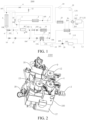
- the present disclosure provides an integrated module 1000 for a vehicle thermal management system, a vehicle thermal management system 2000 having the integrated module 1000, and a vehicle having the vehicle thermal management system 2000.
- the vehicle thermal management system 2000 may include the integrated module 1000, a compressor 1, an indoor condenser 2, an outdoor heat exchanger 5, an indoor evaporator 11, a battery heat exchanger 17, an engine 27, and the like.
- the integrated module 1000 is provided with a number of corresponding interfaces respectively connected to the compressor 1, the indoor condenser 2, the outdoor heat exchanger 5, the indoor evaporator 11, the battery heat exchanger 17, and the like, to form various flow paths through connections with the foregoing thermal management devices, to implement various preset modes of the vehicle thermal management system, for example, an air conditioning cooling mode, a battery cooling mode, a battery heating mode, a heat pump heating mode, an air conditioning dehumidification mode, and an engine heating mode.
- the integrated module 1000 provided in the present disclosure includes a body 100, a number of interfaces, and a valve set 300. At least one flow channel 200 is provided in the body 100.
- the number of interfaces (including two or more) are provided on the body 100 to be in communication with corresponding flow channels 200, and are configured to connect to corresponding thermal management devices (such as the compressor 1, the outdoor heat exchanger 5, and the battery heat exchanger 17) in the thermal management system.
- the number of interfaces include an indoor condenser outlet interface 105, a first interface 101, a second interface 102, a battery heat exchanger first opening interface 109, a battery heat exchanger second opening interface 110, and a compressor inlet interface 106.
- the indoor condenser outlet interface 105 is connected to the first interface 101 through a flow channel 200. In this way, a refrigerant from the indoor condenser 2 can flow into the integrated module 1000 through the indoor condenser outlet interface 105, and can flow out of the integrated module 1000 through the first interface 101.
- the second interface 102 is connected to the battery heat exchanger first opening interface 109 through a flow channel 200, and the battery heat exchanger second opening interface 110 is connected to the compressor inlet interface 106 through a flow channel 200.
- a refrigerant flowing into the integrated module 1000 through the second interface 102 can flow into a first opening of the battery heat exchanger 17 through the battery heat exchanger first opening interface 109, can flow into the integrated module through the battery heat exchanger second opening interface 110 after flowing through the battery heat exchanger 17, and then can flow out of the integrated module 1000 through an outlet of the compressor 1, to flow into the compressor 1.
- the battery heat exchanger 17 is configured to exchange heat with a battery coolant circuit L1 in which a battery 21 is located, and the battery coolant circuit L1 is configured to exchange heat with an engine coolant circuit L3 in which an engine 27 is located.
- the valve set 300 is arranged on the body 100.
- the valve set 300 includes a first expansion valve 16.
- the first expansion valve 16 is arranged on the flow channel 200 between the second interface 102 and the battery heat exchanger first opening interface 109.
- a first port of the first expansion valve 16 is connected to the second interface 102
- a second port of the first expansion valve 16 is connected to the battery heat exchanger first opening interface 109.
- the first expansion valve 16 can throttle and depressurize a refrigerant from the second interface 102.
- the first expansion valve 16 has functions of throttling and performing communication/interception.
- the battery heat exchanger first opening interface 109 is an interface that is on the body 100 and configured to connect to a battery heat exchanger first opening 171 of the battery heat exchanger 17.
- the battery heat exchanger second opening interface 110 is an interface that is on the body 100 and configured to connect to a battery heat exchanger second opening 172 of the battery heat exchanger 17.
- the compressor inlet interface 106 is an interface that is on the body 100 and configured to connect to a refrigerant inlet of the compressor 1.
- the indoor condenser outlet interface 105 is an interface that is on the body 100 and configured to connect to a refrigerant outlet of the indoor condenser 2.
- interfaces connected to thermal management devices are provided on a body 100, and flow channels 200 are provided in the body 100 to replace existing connection pipelines, so that a quantity of connection pipelines in a thermal management system can be reduced, and the thermal management system can be simplified.
- a valve set 300 is integrated on the body 100, so that a quantity of supports for mounting valves can be effectively reduced when maintenance and disassembly are facilitated.
- the design of the flow channels 200 in the body 100 can also reduce weight of the integrated module 1000, thereby facilitating lightweight design of an entire vehicle, and reducing costs and fuel consumption.
- use of components is reduced, so that an arrangement space of the entire vehicle can also be reduced.
- the flow channels 200 may be flexibly designed on the body 100 of the integrated module 1000, so that arrangement positions of the valves may also be flexibly selected, to adapt to different entire vehicle arrangement, thereby facilitating platform design of the entire vehicle.
- the thermal management devices can be systematically integrated, thereby facilitating integration of the thermal management system. In this way, the vehicle thermal management system can be simplified overall, costs can be reduced, and the vehicle thermal management system can also be easy to assemble.
- a battery heat exchanger 17 is arranged, so that an air conditioning system in which a compressor 1 is located can exchange heat with a battery 21 (such as a power battery) or the like of the vehicle, to heat or cool the battery 21.
- the air conditioning system in which the compressor 1 is located and the battery 21 can exchange heat with a flow path in which an engine 27 is located, so that waste heat of the engine 27 can be utilized, thereby improving a utilization rate of energy of the vehicle thermal management system, and achieving energy saving.
- the integrated module 1000 is connected to other heat exchange devices in the thermal management system, so that other preset thermal management modes can be implemented.
- a refrigerant enters an indoor condenser 2 from an outlet of the compressor 1, and is condensed and releases heat in the indoor condenser 2, to implement a passenger compartment heating mode. Then, the refrigerant enters the integrated module 1000 from an indoor condenser outlet interface 105, and flows out of the integrated module 1000 from the first interface 101.
- the refrigerant After passing through a liquid storage drying tank 7 and a coaxial tube 8 (for details, refer to below), the refrigerant enters the integrated module 1000 from a second interface 102. Then, the refrigerant may flow into a first expansion valve 16, and is throttled and depressurized by the first expansion valve 16. In this way, the refrigerant can absorb heat in the battery heat exchanger 17, thereby recovering waste heat of the engine 27. The recovered heat may be used to heat the refrigerant in the air conditioning system.
- a blower or a fan may be used in cooperation to directly blow heat released by the indoor condenser 2 to a riding room, to improve utilization efficiency of the heat.
- the heat released by the indoor condenser 2 may also be transferred to the riding room by using a heater core 23. This is not limited in the present disclosure.
- an integrated wiring harness 400 may be used to connect the thermal management devices.
- the integrated wiring harness 400 may be arranged on the integrated module 1000.
- the integrated module 1000 may further include the battery heat exchanger 17.
- the battery heat exchanger 17 is arranged on the body 100.
- the battery heat exchanger 17 further includes a battery heat exchanger third opening 173 and a battery heat exchanger fourth opening 174.
- the battery heat exchanger third opening 173 and the battery heat exchanger fourth opening 174 are configured to connect to the battery coolant circuit L1.
- the battery heat exchanger 17 is integrated on the body 100, so that integration of the integrated module 1000 can be further improved, and a space required by the vehicle thermal management system can be further reduced.
- the battery heat exchanger 17 is integrated on the body 100, so that a connection pipeline between the battery heat exchanger 17 and the air conditioning system can be shortened or eliminated, thereby reducing costs.
- the battery heat exchanger first opening 171 of the battery heat exchanger 17 and the battery heat exchanger first opening interface 109 on the body 100 may be directly connected or connected through a short pipeline
- the battery heat exchanger second opening 172 and the battery heat exchanger second opening interface 110 on the body 100 may be directly connected or connected through a short pipeline.
- the number of interfaces may further include an outdoor heat exchanger first opening interface 107 and an outdoor heat exchanger second opening interface 108.
- the indoor condenser outlet interface 105 is connected to the first interface 101 through the flow channel 200.
- the indoor condenser outlet interface 105 is connected to the outdoor heat exchanger first opening interface 107 through a flow channel 200.
- the valve set 300 may further include a first switch valve 12 and a second switch valve 4.
- the first switch valve 12 is located on the flow channel 200 between the indoor condenser outlet interface 105 and the first interface 101, to implement communication and interception of the flow channel 200 between the indoor condenser outlet interface 105 and the first interface 101.
- the second switch valve 4 is located on the flow channel 200 between the indoor condenser outlet interface 105 and the outdoor heat exchanger first opening interface 107, to implement communication and interception of the flow channel 200 between the indoor condenser outlet interface 105 and the outdoor heat exchanger first opening interface 107.
- the integrated module 1000 when the integrated module 1000 is applied to the vehicle thermal management system 2000, through cooperation of the first switch valve 12, the second switch valve 4, and the first expansion valve 16, different thermal management modes of the vehicle thermal management system may be implemented. For example, an independent air conditioning cooling mode and an independent heat pump mode may be implemented.
- the first switch valve 12 When a passenger compartment in summer needs to be cooled to implement the air conditioning cooling mode, the first switch valve 12 may be closed, and the second switch valve 4 may be opened. In this way, after passing through the indoor condenser 2 (no heat is released in this case), a refrigerant flows out of the integrated module 1000 through the outdoor heat exchanger first opening interface 107 of the body 100, and enters the outdoor heat exchanger 5.
- the refrigerant flowing through the outdoor heat exchanger 5 may enter the body 100 through the outdoor heat exchanger second opening interface 108 of the body 100, and then may flow out of the body 100 through a third interface 103 (refer to below), so that the refrigerant flows into the indoor evaporator 11 for evaporation and heat absorption.
- the first switch valve 12 may be opened, and the second switch valve 4 may be closed.
- the refrigerant may pass through the first switch valve 12, enter a first opening through a second opening of the outdoor heat exchanger 5 and flow through the outdoor heat exchanger 5, and then return to the compressor 1. In this way, heat of an external environment can be recovered, thereby achieving a heat pump effect.
- the first switch valve 12 may be opened, so that another part of the refrigerant enters the battery heat exchanger 17 after passing through the first switch valve 12, to absorb heat of the battery 21 or the engine 27, to heat the passenger compartment. In this way, it is ensured that a heating effect of the passenger compartment meets a requirement.
- the number of interfaces may further include a third interface 103.
- the second interface 102 is connected to the third interface 103 through a flow channel 200.
- the third interface 103 is configured to connect to a first port of a second expansion valve 10.
- a second port of the second expansion valve 10 is connected to a refrigerant inlet of the indoor evaporator 11, to throttle and depressurize a refrigerant before the refrigerant enters the indoor evaporator 11. In this way, the refrigerant can be evaporated and absorb heat in the indoor evaporator 11.
- the valve set 300 further includes a third switch valve 9.
- the third switch valve 9 is arranged on the flow channel 200 between the second interface 102 and the third interface 103, to implement communication and interception of the flow channel 200 between the second interface 102 and the third interface 103.
- the air conditioning cooling mode can be implemented.
- the first switch valve 12 and the third switch valve 9 may be opened, and the second switch valve 4 and the first expansion valve 16 may be closed.
- a refrigerant may pass from the compressor 1, the indoor condenser 2 (in this case, the indoor condenser 2 may not exchange heat, and is only used as a channel through which the refrigerant flows), the third switch valve 9, and the second expansion valve 10 successively.
- the refrigerant is throttled and depressurized, and flows into the indoor evaporator 11 to be evaporated in the indoor evaporator 11. In this way, the air conditioning cooling mode is implemented.
- the battery 21 may be further cooled when the air conditioning cooling mode is implemented.
- the second expansion valve 10 may be used as a thermal expansion valve, which can achieve a low cost effect when the refrigerant can be throttled and depressurized.
- an electronic expansion valve may be used to replace the third switch valve 9 and the second expansion valve 10 in this implementation.
- the second expansion valve 10 may be integrated on the body 100, or may be connected to a corresponding interface on the body 100 through a pipeline. This is not limited in the present disclosure.
- the valve set 300 further includes the second expansion valve 10.
- the first port of the second expansion valve 10 is connected to the third interface 103.
- the second port of the second expansion valve 10 is configured to connect to the refrigerant inlet of an indoor evaporator 11.
- the second expansion valve 10 is integrated on the body 100. In this way, a corresponding connection pipeline can be eliminated, costs can be reduced, and an overall volume of the thermal management system can be reduced.
- the interfaces may further include a fourth interface 104.
- the fourth interface 104 is connected to a second interface 102 through a flow channel 200.
- the fourth interface 104 is configured to connect to a first port of a third expansion valve 13.
- a second port of the third expansion valve 13 is connected to the outdoor heat exchanger second opening interface 108.
- the valve set 300 may further include a fourth switch valve 15.
- the fourth switch valve 15 is arranged on a flow channel 200 between the second switch valve 4 and the compressor inlet interface 106. In this way, through cooperation of the first switch valve 12, the second switch valve 4, the third switch valve 9, the fourth switch valve 15, and the third expansion valve 13, a heat pump mode with an energy saving effect can be implemented.
- the first switch valve 12, the fourth switch valve 15, and the third expansion valve 13 may be opened, and the second switch valve 4 and the third switch valve 9 may be closed.
- a refrigerant flows through the indoor condenser 2, the first switch valve 12, the third expansion valve 13, the outdoor heat exchanger 5, and the fourth switch valve 15 successively, and then returns to the compressor 1.
- the refrigerant passes through the outdoor heat exchanger 5, and absorbs heat from the external environment through a heat pump function of the outdoor heat exchanger 5, so that energy saving can be achieved.
- the integrated module 1000 may further include a pressure sensor 3.
- a fifth interface is further provided on the body 100.
- a detection end of the pressure sensor 3 extends into the fifth interface, to detect a pressure of a refrigerant entering the integrated module 1000 through the indoor condenser outlet interface 105.
- the integrated module 1000 further includes a pressure-temperature sensor 18.
- a sixth interface is further provided on the body 100.
- a detection end of the second pressure-temperature sensor 18 extends into the sixth interface, to detect a pressure and a temperature of a refrigerant entering the integrated module 1000 through the battery heat exchanger second opening interface 110.
- the pressure sensor 3 when the pressure sensor 3 detects that a pressure of a refrigerant flowing out of an outlet of the indoor condenser 2 is excessively high or excessively low, adjustment may be performed in time.
- the pressure-temperature sensor 18 detects that a pressure and a temperature of a refrigerant flowing out of the battery heat exchanger second opening 172 is excessively high or excessively low, an opening degree of the first expansion valve 16 and/or the second expansion valve 10 may be correspondingly adjusted to adjust a flow rate.
- the pressure-temperature sensor 18 may be a PT sensor.
- Specific arrangement positions of the interfaces and the valve set 300 on the body 100 are not limited in the present disclosure, and may be specifically determined according to specific arrangement positions of thermal management devices of the vehicle thermal management system on the vehicle, for example, the compressor 1, the indoor condenser 2, the outdoor heat exchanger 5, the indoor evaporator 11, and the battery heat exchanger 17.
- the body 100 may have a top surface 1001, a bottom surface 1002, and a side surface 1003 connected between the top surface 1001 and the bottom surface 1002.
- the valve set 300 is arranged on the top surface 1001.
- the number of interfaces are provided on the side surface 1003 and the bottom surface 1002. In other words, in the number of interfaces, some interfaces may be located on the side surface 1003, and some interfaces may be located on the bottom surface 1002.
- the bottom surface 1002 is used for mounting the battery heat exchanger 17.
- valve set 300 is uniformly arranged on an upper side of the body 100, the battery heat exchanger 17 is arranged on the other side of the body 100, and the number of interfaces other than interfaces connected to the battery 21 are provided on the side surface of the body 100.
- the manner of concentrated arrangement after classification facilitates overall design of the body 100.
- a specific shape of the body 100 is not limited in the present disclosure.
- the body 100 may be generally a cuboid structure.
- the side surface 1003 of the body 100 includes a first side surface 111, a second side surface 112, a third side surface 113, and a fourth side surface 114 that are connected to form an annular structure.
- the indoor condenser outlet interface 105 is provided on the first side surface 111.
- the outdoor heat exchanger first opening interface 107 is provided on the second side surface 112.
- the outdoor heat exchanger second opening interface 108, the first interface 101, and the fourth interface 104 are provided on the third side surface 113.
- the second interface 102, the third interface 103, and the compressor inlet interface 106 are provided on the fourth side surface 114. Different interfaces are provided on different side surfaces, so that arrangement of thermal management devices in the vehicle along a number of directions can be adapted, thereby improving versatility of the integrated module 1000.
- a segment of flow channel is shared between the indoor condenser outlet interface 105 and the first jack 1001 and between the indoor condenser outlet interface 105 and the second jack 1002.
- the first direction is a direction of a connection line between the first side surface 111 and the third side surface 113.
- the first flow channel segment 201 forms a straight flow channel segment, so that a distance between the indoor condenser outlet interface 105 and the first jack 1001 and a distance between the indoor condenser outlet interface 105 and the second jack 1002 can be shortened. In this way, a refrigerant can be rapidly transferred to positions of the first switch valve 12 and the second switch valve 4, to distribute the refrigerant to corresponding thermal management devices.
- segment of flow channel is shared between the indoor condenser outlet interface 105 and the first jack 1001 and between the indoor condenser outlet interface 105 and the second jack 1002, so that a quantity of arranged flow channels and difficulty of processing the flow channels can be reduced.
- a flow channel 200 between the outdoor heat exchanger first opening interface 107 and the compressor inlet interface 106 includes at least a second flow channel segment 202 extending along a second direction.
- the compressor inlet interface 106 is located at an upper end of the second flow channel segment 202.
- the second direction is a direction of a connection line between the top surface 1001 and the bottom surface 1002, that is, an up-down direction of a figure plane of FIG. 7 .
- the second flow channel segment 202 is arranged along the up-down direction, and the compressor inlet interface 106 is located at the upper end of the second flow channel segment 202.
- liquid in a refrigerant can fall downward due to gravity, so that a liquid refrigerant that may exist can be removed at this stage.
- the second flow channel segment 202 achieves a gas-liquid separator effect.
- the first flow channel segment 201 is closer to the second side surface 112
- the second flow channel segment 202 is closer to the fourth side surface 114.
- a refrigerant flowing out of the indoor condenser 2 flows in the first flow channel segment 201 and has a high temperature.
- a refrigerant that is to return to the compressor 1 flows in the second flow channel segment 202, has a low temperature, and also requires the low temperature. Therefore, the first flow channel segment 201 and the second flow channel segment 202 are arranged spaced away by a large distance, so that impact between temperatures of the refrigerant in the first flow channel segment 201 and the refrigerant in the second flow channel segment 202 can be avoided. In this way, the refrigerant can enter the compressor 1 at the low temperature, and the compressor 1 can normally operate.
- the top surface of the body 100 is further provided with a third jack 1003, a fourth jack 1004, and a fifth jack 1005.
- the third jack 1003 may be configured to mount the third switch valve 9.
- the fourth jack 1004 may be configured to mount the fourth switch valve 15.
- the fifth jack 1005 may be configured to mount the first expansion valve 16.
- connections between the number of flow channels 200 may be configured as smooth transitions.
- connection locations of different flow channels 200 are curved connections. This greatly reduces the flow resistance, so that system performance is ensured.
- a process such as milling or soldering may be used to process the connection portions of the smooth transitions.
- the vehicle thermal management system 2000 may further include the outdoor heat exchanger 5.
- a refrigerant outlet of a compressor 1 is connected to a refrigerant inlet of the indoor condenser 2.
- a refrigerant outlet of the indoor condenser 2 is connected to the indoor condenser outlet interface 105.
- a refrigerant inlet of the compressor 1 is connected to the compressor inlet interface 106.
- a first opening of the outdoor heat exchanger 5 is connected to the refrigerant outlet of the indoor condenser 2 through a flow channel 200 of the integrated module 1000, or the first opening of the outdoor heat exchanger 5 is connected to the refrigerant inlet of the compressor 1 through a flow channel 200 of the integrated module 1000.
- a second opening of the outdoor heat exchanger 5 is connected to the first interface 101.
- the vehicle thermal management system 2000 may further include a coaxial tube 8.
- the coaxial tube 8 may include an inner tube and an outer tube sleeved mutually. An inner space of the inner tube defines a first channel 81. A space between the inner tube and the outer tube defines a second channel 82.
- the first channel 81 and the second channel 82 are configured to cause a temperature of a refrigerant flowing through the first channel 81 to be higher than a temperature of a refrigerant flowing through the second channel 82.
- the outdoor heat exchanger 5 includes the first opening and the second opening. When one of the first opening and the second opening is used as a refrigerant inlet, the other is used as a refrigerant outlet.
- a refrigerant inlet of the first channel 81 is connected to the second opening of the outdoor heat exchanger 5 through a flow channel 200 of the integrated module 1000, or the refrigerant inlet of the first channel 81 is connected to the refrigerant outlet of the indoor condenser 2 through a flow channel 200 of the integrated module 1000.
- a refrigerant outlet of the first channel 81 is connected to the second interface 102.
- a refrigerant inlet of the second channel 82 is connected to the compressor inlet interface 106.
- a refrigerant outlet of the second channel 82 is connected to the refrigerant inlet of the compressor 1.
- the high-temperature refrigerant may flow into the first channel 81; and a part of a refrigerant in a liquid state flowing back into the refrigerant inlet of the compressor 1 through the second channel 82 may be vaporized by the high-temperature refrigerant in the first channel 81.
- the refrigerant entering the refrigerant inlet of the compressor 1 is in a gas state, and a gas-liquid separator effect is achieved.
- a quantity of used pipelines is reduced, so that the structure of the vehicle thermal management system can be simplified.
- the vehicle thermal management system 2000 may further include a liquid storage drying tank 7.
- the liquid storage drying tank 7 may be arranged on an upstream part of the coaxial tube 8.
- the liquid storage drying tank 7 is configured to absorb moisture in a refrigerant flow path and filter out impurities.
- the vehicle thermal management system 2000 may further include a first one-way valve 6 and a second one-way valve 14.
- the first one-way valve 6 is arranged on a flow path between a second outlet of the outdoor heat exchanger 5 and the liquid storage drying tube 7, to allow a refrigerant to flow from a side of the outdoor heat exchanger 5 to a side of the liquid storage drying tube 7.
- the second one-way valve 14 is arranged between the third expansion valve 13 and the second outlet of the outdoor heat exchanger 5, to allow a refrigerant to flow from a side of the third expansion valve 13 side to the side of the outdoor heat exchanger 5.
- a type of the outdoor heat exchanger 5 is not limited in the present disclosure.
- the outdoor heat exchanger 5 may be an evaporative condenser, to improve a heat exchange effect.
- An operating principle of the evaporative condenser is known to a person skilled in the art, and is not described herein.
- the vehicle thermal management system 2000 may further include the engine 27, the battery coolant circuit L1, a first pump 19, the battery 21, and a first heat exchanger 22.
- a first end and a second end of the battery coolant circuit L1 are respectively connected to the battery heat exchanger third opening 173 and the battery heat exchanger fourth opening 174.
- the first pump 19, the battery 21, and the first heat exchanger 22 are connected in series (for example, in successive series) on the battery coolant circuit L1.
- the first heat exchanger 22 is configured to exchange heat with the engine coolant circuit L3, that is, exchange heat with the engine 27.
- the first pump 19 may be opened, so that a coolant in the battery coolant circuit L1 flows through the battery 21 and the battery heat exchanger 17.
- the first expansion valve 16 may be used to throttle and depressurize a refrigerant, to atomize the refrigerant.
- the atomized refrigerant enters the battery heat exchanger 17 and absorbs heat in the battery coolant circuit L1, thereby cooling the battery 21.
- the first pump 19 may be opened, so that the coolant in the battery coolant circuit L1 flows through the battery 21 and the first heat exchanger 22.
- the first heat exchanger 22 may perform heat exchange on heat of the engine 27, and the heat of the engine 27 is used to heat the battery 21.
- the vehicle thermal management system 2000 may further include a short circuit branch L11 and a three-way valve 20.
- a first port 201 and a second port 202 of the three-way valve 20 are connected between the first pump 19 and the battery 21.
- a third port 203 of the three-way valve 20 is connected to a flow path between the battery 21 and the first heat exchanger 22 through the short circuit branch L11.
- the short circuit branch L11 and the battery 21 are arranged in parallel.
- the first port 201 and the second port 202 of the three-way valve 20 may come into communication, to open the first pump 19, so that a coolant in the battery coolant circuit L1 flows through the battery 21 and the battery heat exchanger 17.
- the first expansion valve 16 may be used to throttle and depressurize a refrigerant, to atomize the refrigerant.
- the atomized refrigerant enters the battery heat exchanger 17 and absorbs heat in the battery coolant circuit L1, thereby cooling the battery 21.
- the first port 201 and the second port 202 of the three-way valve 20 may come into communication, to open the first pump 19, so that the coolant in the battery coolant circuit L1 flows through the battery 21 and the first heat exchanger 22.
- the first heat exchanger 22 may perform heat exchange on heat of the engine 27, and the heat of the engine 27 is used to heat the battery 21.
- the coolant may flow through the short circuit branch L11 in the battery coolant circuit L1.
- the engine 27 may be connected to the battery coolant circuit L1 by using any suitable coolant flow path, to exchange heat with the first heat exchanger 22.
- the engine coolant circuit L3 may include a first circuit L31 and a second circuit L32.
- the vehicle thermal management system 2000 may further include a heater core 23, a PTC 24, a second pump 25, and a four-way valve 26. A first end and a second end of the first circuit L31 are respectively connected to two ports of the first heat exchanger 22, for example, connected to a first port and a second port of the first heat exchanger 22.
- the heater core 23, the PTC 24, the second pump 25, and the four-way valve 26 are connected in series (for example, in successive series) on the first circuit L31.
- the engine 27 is arranged on the second circuit L32.
- a first end and a second end of the second circuit L32 are respectively connected to other two ports of the four-way valve 26.
- the four-way valve 26 is connected to the first circuit L31 through two ports (for example, a first port 261 and a second port 262 of the four-way valve 26), and is connected to the second circuit L32 through the other two ports (for example, a third port 263 and a fourth port 264 of the four-way valve 26).
- the first circuit L31 may come into communication with the second circuit L32 through the three-way valve 20, and the second pump 25 may be opened, to transfer the heat to the passenger compartment.
- the heat of the engine 27 may be first transferred to the first circuit L31 through the coolant flow path of the engine 27, and then the first heat exchanger 22 exchanges heat with the battery coolant circuit L1, to heat a coolant in the battery coolant circuit L1, thereby heating the battery 21.
- the PTC 24 may be opened to heat the passenger compartment.
- waste heat of the engine 27 may alternatively be used for heat exchange with the first heat exchanger 22 through the first circuit L31, and then the first heat exchanger 22 exchanges heat with the air conditioning system through the battery coolant circuit L1 and the battery heat exchanger 17, to provide a heat source for the air conditioning system.
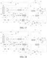
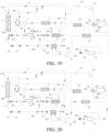
- an air conditioning independent cooling mode a battery independent cooling mode, an air conditioning cooling and battery cooling dual-open mode, an air source heat pump mode, a coolant source heat pump mode, a PTC heating mode, an engine heating mode, an engine waste heat heating battery mode, a PTC heating battery mode, a dehumidification mode, and a passenger compartment heating and battery cooling mode.
- a specific flowing process of a refrigerant in the mode is as follows: The refrigerant flows into the indoor condenser 2 from the refrigerant outlet of the compressor 1. The refrigerant flowing out of the refrigerant outlet of the indoor condenser 2 enters the integrated module 1000 from the indoor condenser outlet interface 105 on the body 100, and flows out of the integrated module 1000 from a seventh interface on the body 100 after passing through the pressure sensor 3 and the second switch valve 4.
- the refrigerant enters the integrated module 1000 from an eighth interface after flowing through the outdoor heat exchanger 5, and flows out of the integrated module 1000 from the first interface 101 after passing through the first one-way valve 6. Then, the refrigerant enters the integrated module 1000 from the second interface 102 after passing through the liquid storage drying tank 7 and the first channel 81 of the coaxial tube 8, and flows out of the integrated module 1000 from the third interface 103 after passing through the third switch valve 9. Under action of the second expansion valve 10, the refrigerant is throttled and depressurized.
- a low-temperature and low-pressure refrigerant can be evaporated and absorb heat in the indoor evaporator 11, and the refrigerant flowing out of the refrigerant outlet of the indoor evaporator 11 returns to the compressor 1 after passing through the second channel 82 of the coaxial tube 8. In this way, air conditioning independent cooling can be implemented.
- Pipelines may be used to connect the compressor 1 to the indoor condenser 2, the compressor 1 to the coaxial tube 8, and each interface of the integrated module 1000 to a corresponding heat exchanger.
- the indoor condenser 2 is used as a flow channel 200 for passing.
- the mode may be performed.
- specific flowing processes of a refrigerant and a coolant in the mode are as follows:
- the refrigerant flows into the indoor condenser 2 from the refrigerant outlet of the compressor 1.
- the refrigerant flowing out of the refrigerant outlet of the indoor condenser 2 enters the integrated module 1000 from the indoor condenser outlet interface 105, and flows out of the integrated module 1000 from a seventh interface on the body 100 after passing through the pressure sensor 3 and the second switch valve 4.
- the refrigerant enters the integrated module 1000 from an eighth interface after flowing through the outdoor heat exchanger 5, and flows out of the integrated module 1000 from the first interface 101 after passing through the first one-way valve 6. Then, the refrigerant enters the integrated module 1000 from the second interface 102 after passing through the liquid storage drying tank 7 and the first channel 81 of the coaxial tube 8. Under action of the first expansion valve 16, the refrigerant is throttled and depressurized. In this way, a low-temperature and low-pressure refrigerant flows into the battery heat exchanger 17 through the battery heat exchanger first opening 171, and can absorb heat in the battery heat exchanger 17.
- the refrigerant flowing out of the battery heat exchanger second opening 172 flows out of the integrated module 1000 from the compressor inlet interface 106 on the body 100, and returns to the compressor 1 after passing through the second channel 82 of the coaxial tube 8.
- the battery coolant circuit L1 after passing through the first pump 19, and the first port 201 and the second port 202 of the three-way valve 20 successively, the coolant enters the battery 21. Then, the coolant passes through the first heat exchanger 22 and enters the battery heat exchanger 17, and finally returns to the first pump 19.
- the indoor condenser 2 may not release heat, and the indoor condenser 2 is used as a flow channel 200 for passing.
- a specific flowing process of a refrigerant in the mode is as follows: The refrigerant flows into the indoor condenser 2 from the refrigerant outlet of the compressor 1. The refrigerant flowing out of the refrigerant outlet of the indoor condenser 2 enters the integrated module 1000 from the indoor condenser outlet interface 105, and flows out of the integrated module 1000 from a seventh interface on the body 100 after passing through the pressure sensor 3 and the second switch valve 4.
- the refrigerant enters the integrated module 1000 from an eighth interface after flowing through the outdoor heat exchanger 5, and flows out of the integrated module 1000 from the first interface 101 after passing through the first one-way valve 6. Then, the refrigerant enters the integrated module 1000 from the second interface 102 after passing through the liquid storage drying tank 7 and the first channel 81 of the coaxial tube 8. Then, the refrigerant has two paths. In a first path, the refrigerant flows out of the integrated module 1000 from the third interface 103 after passing through the third switch valve 9. Under action of the second expansion valve 10, the refrigerant is throttled and depressurized.
- a low-temperature and low-pressure refrigerant can be evaporated and absorb heat in the indoor evaporator 11, and the refrigerant flowing out of the refrigerant outlet of the indoor evaporator 11 returns to the compressor 1 after passing through the second channel 82 of the coaxial tube 8. In this way, air conditioning cooling can be implemented.
- the refrigerant is throttled and depressurized. In this way, a low-temperature and low-pressure refrigerant flows into the battery heat exchanger 17 through the battery heat exchanger first opening 171, and can absorb heat in the battery heat exchanger 17, to absorb a temperature of the coolant in the battery coolant circuit L1. In this way, the battery 21 is cooled.
- the refrigerant flowing out of the battery heat exchanger second opening 172 flows out of the integrated module 1000 from the compressor inlet interface 106 on the body 100, and returns to the compressor 1 after passing through the second channel 82 of the coaxial tube 8. In this way, the air conditioning cooling and battery cooling dual-open mode can be implemented.
- the flowing process of the coolant in the battery coolant circuit L1 is the same as the flowing process of the coolant in the independent cooling of the battery 21. Details are not described herein again.
- a driving mode is an EV mode
- the environmental temperature is higher than -10°C
- the mode may be performed, that is, an energy-saving heat pump air conditioning system may be used to generate heat.
- a specific flowing process of a refrigerant is as follows: The refrigerant flows into the indoor condenser 2 from the refrigerant outlet of the compressor 1. The refrigerant releases heat in the indoor condenser 2, to heat the passenger compartment.
- the refrigerant flowing out of the refrigerant outlet of the indoor condenser 2 enters the integrated module 1000 from the indoor condenser outlet interface 105, and flows out of the integrated module 1000 from the first interface 101 on the body 100 after passing through the pressure sensor 3 and the first switch valve 12. Then, the refrigerant enters the integrated module 1000 from the second interface 102 after passing through the liquid storage drying tank 7 and the first channel 81 of the coaxial tube 8, and then passes through the third expansion valve 13 and the second one-way valve 14. Under action of the third expansion valve 13, the refrigerant is throttled and depressurized.
- a low-temperature and low-pressure refrigerant flows into the outdoor heat exchanger 5 through the second opening of the outdoor heat exchanger 5, and can absorb heat in the outdoor heat exchanger 5, to absorb a temperature of the external environment.
- the refrigerant flowing out of the first opening of the outdoor heat exchanger 5 passes through the fourth switch valve 15, flows out of the integrated module 1000 from the compressor inlet interface 106 on the body 100, and returns to the compressor 1 after passing through the second channel 82 of the coaxial tube 8.
- a water temperature of the engine 27 is still relatively high.
- waste heat of the engine 27 can be fully utilized to provide a heat source for a heat pump, to heat the passenger compartment.
- specific flowing processes of a refrigerant and a coolant are as follows: The refrigerant flows into the indoor condenser 2 from the refrigerant outlet of the compressor 1. The refrigerant releases heat in the indoor condenser 2, to heat the passenger compartment.
- the refrigerant flowing out of the refrigerant outlet of the indoor condenser 2 enters the integrated module 1000 from the indoor condenser outlet interface 105, and flows out of the integrated module 1000 from the first interface 101 on the body 100 after passing through the pressure sensor 3 and the first switch valve 12. Then, the refrigerant enters the integrated module 1000 from the second interface 102 after passing through the liquid storage drying tank 7 and the first channel 81 of the coaxial tube 8, and then passes through the first expansion valve 16. Under action of the first expansion valve 16, the refrigerant is throttled and depressurized. In this way, a low-temperature and low-pressure refrigerant flows into the battery heat exchanger 17 through the battery heat exchanger first opening 171, and can absorb heat in the battery heat exchanger 17. The refrigerant flowing out of the battery heat exchanger second opening 172 flows out of the integrated module 1000 from the compressor inlet interface 106 on the body 100, and returns to the compressor 1 after passing through the second channel 82 of the coaxial tube 8.
- the coolant In the battery coolant circuit L1, after passing through the first pump 19, the first port 201 and the third port 203 of the three-way valve 20, the short circuit branch L11, and the first heat exchanger 22 successively, the coolant enters the battery heat exchanger 17 to exchange heat with the refrigerant, and finally returns to the first pump 19.
- the coolant In the first circuit L31 and the second circuit L32, after passing through the second pump 25, the PTC 24, and the heater core 23 successively, the coolant enters the first heat exchanger 22 for heat exchange. Then, the coolant enters the second circuit L32 through the first port 261 and the third port 263 of the four-way valve 26. Then, the coolant enters the engine 27, and returns to the second pump 25 through the fourth port 264 and the second port 262 of the four-way valve 26. In this way, the heat of the engine 27 can be used as the heat source, to implement the coolant heat pump mode.
- the PTC 24 may not perform heating.
- the air source heat pump and a water source heat pump operate may also operate in parallel at the same time, thereby more fully utilizing the waste heat and reducing energy consumption.
- the air source heat pump and a water source heat pump operate may also operate in parallel at the same time, thereby more fully utilizing the waste heat and reducing energy consumption.
- the PTC 24 may also be opened for heating, to perform the PTC heating mode.
- a specific flowing process of a coolant in the first circuit L31 is as follows: After passing through the second pump 25, the PTC 24, the heater core 23, the first heat exchanger 22, and the first port 261 and the second port 262 of the four-way valve 26 successively, the coolant returns to the second pump 25. In this way, the strong heating requirement of the passenger compartment is met by the PTC 24.
- a water temperature of the engine 27 may be used for heating.
- a specific flowing process of a coolant in the first circuit L31 and the second circuit L32 is as follows: After passing through the second pump 25, the PTC 24, the heater core 23, the first heat exchanger 22, and the first port 261 and the third port 263 of the four-way valve 26 successively, the coolant enters the engine 27, and returns to the second pump 25 through the fourth port 264 and the second port 262 of the four-way valve 26. It may be understood that, in the mode, the PTC 24 may not perform heating.
- waste heat of the engine 27 may be used to heat the battery, to reduce energy consumption.
- a specific flowing process of a coolant is as follows: In the battery coolant circuit L1, the coolant passes through the first pump 19, the first port 201 and the second port 202 of the three-way valve 20, the battery 21, the first heat exchanger 22, and the battery heat exchanger 17 successively, and finally returns to the first pump 19.
- the coolant In the first circuit L31 and the second circuit L32, after passing through the second pump 25, the PTC 24, and the heater core 23 successively, the coolant enters the first heat exchanger 22 for heat exchange, so that the coolant in a coolant flow path in which the battery 21 is located is heated. In this way, the battery 21 is heated. Then, the coolant enters the second circuit L32 through the first port 261 and the third port 263 of the four-way valve 26. Then, the coolant enters the engine 27, and returns to the second pump 25 through the fourth port 264 and the second port 262 of the four-way valve 26.
- the PTC 24 may not perform heating.
- the battery 21 may alternatively be heated by using the PTC 24.
- a specific flowing process of a coolant is as follows: In the battery coolant circuit L1, the coolant passes through the first pump 19, the first port 201 and the second port 202 of the three-way valve 20, the battery 21, the first heat exchanger 22, and the battery heat exchanger 17 successively, and finally returns to the first pump 19.
- the first circuit L31 after passing through the second pump 25, the PTC 24, the heater core 23, the first heat exchanger 22, and the first port 261 and the second port 262 of the four-way valve 26, the coolant returns to the second pump 25.
- heat of the PTC 24 may be transferred to the battery coolant circuit L1, to heat the battery 21.
- the dehumidification mode may be divided into a self-circulating dehumidification mode and a parallel dehumidification mode.
- a flowing process of a refrigerant is as follows: The refrigerant flows into the indoor condenser 2 from the refrigerant outlet of the compressor 1. The refrigerant releases heat in the indoor condenser 2. The refrigerant flowing out of the refrigerant outlet of the indoor condenser 2 enters the integrated module 1000 from the indoor condenser outlet interface 105, and flows out of the integrated module 1000 from the first interface 101 on the body 100 after passing through the pressure sensor 3 and the first switch valve 12.
- the refrigerant enters the integrated module 1000 from the second interface 102 after passing through the liquid storage drying tank 7 and the first channel 81 of the coaxial tube 8, and then passes through the third switch valve 9 and the second expansion valve 10. Under action of the second expansion valve 10, the refrigerant is throttled and depressurized. In this way, a low-temperature and low-pressure refrigerant flows into the indoor evaporator 11, and can be evaporated and absorb heat in the indoor evaporator 11. The refrigerant flowing out of the indoor evaporator 11 returns to the compressor 1 after passing through the second channel 82 of the coaxial tube 8.
- the refrigerant flowing out of the outlet of the compressor 1 releases heat in the indoor condenser 2, and the refrigerant entering the indoor evaporator 11 is evaporated and absorbs heat of the indoor environment.
- humid indoor air reaches a dew point temperature, is condensed into water, and is exhausted, to achieve a dehumidification effect.
- a dehumidified environment is added with the heat released from the indoor condenser 2.
- the environmental temperature reaches a comfortable temperature, and a fan can blow air into the passenger compartment, to achieve a comfortable environmental temperature of the passenger compartment.
- a flowing process of a refrigerant is as follows: The refrigerant flows into the indoor condenser 2 from the refrigerant outlet of the compressor 1. The refrigerant releases heat in the indoor condenser 2. The refrigerant flowing out of the refrigerant outlet of the indoor condenser 2 enters the integrated module 1000 from the indoor condenser outlet interface 105, and flows out of the integrated module 1000 from the first interface 101 on the body 100 after passing through the pressure sensor 3 and the first switch valve 12.
- the refrigerant enters the integrated module 1000 from the second interface 102 after passing through the liquid storage drying tank 7 and the first channel 81 of the coaxial tube 8. Then, the refrigerant has two paths. In a first path, the refrigerant flows out of the integrated module 1000 through the third interface 103 on the body 100, and then passes through the third switch valve 9 and the second expansion valve 10. Under action of the second expansion valve 10, the refrigerant is throttled and depressurized. In this way, a low-temperature and low-pressure refrigerant flows into the indoor evaporator 11, and can be evaporated and absorb heat in the indoor evaporator 11.
- the refrigerant flowing out of the indoor evaporator 11 returns to the compressor 1 after passing through the second channel 82 of the coaxial tube 8.
- the refrigerant passes through the third expansion valve 13 and the second one-way valve 14.
- the refrigerant is throttled and depressurized. In this way, a low-temperature and low-pressure refrigerant flows into the outdoor heat exchanger 5 through the second opening of the outdoor heat exchanger 5, and can absorb heat in the outdoor heat exchanger 5, to absorb a temperature of the external environment.
- the refrigerant flowing out of the first opening of the outdoor heat exchanger 5 passes through the fourth switch valve 15, flows out of the integrated module 1000 from the compressor inlet interface 106 on the body 100, and returns to the compressor 1 after passing through the second channel 82 of the coaxial tube 8.
- flow paths of a refrigerant and a coolant are as follows: The refrigerant flows into the indoor condenser 2 from the refrigerant outlet of the compressor 1. The refrigerant releases heat in the indoor condenser 2.
- the refrigerant flowing out of the refrigerant outlet of the indoor condenser 2 enters the integrated module 1000 from the indoor condenser outlet interface 105, and flows out of the integrated module 1000 from the first interface 101 on the body 100 after passing through the pressure sensor 3 and the first switch valve 12. Then, the refrigerant enters the integrated module 1000 from the second interface 102 after passing through the liquid storage drying tank 7 and the first channel 81 of the coaxial tube 8, and then passes through the first expansion valve 16. Under action of the first expansion valve 16, the refrigerant is throttled and depressurized.
- a low-temperature and low-pressure refrigerant flows into the battery heat exchanger 17, and absorbs, in the heat exchanger of the battery 21, a temperature of the coolant in a coolant flow path in which the battery 21 is located. In this way, the battery 21 is cooled.
- the refrigerant flowing out of the indoor evaporator 11 returns to the compressor 1 after passing through the second channel 82 of the coaxial tube 8.
- the refrigerant flowing out of the battery heat exchanger 17 flows out of the integrated module 1000 from the compressor inlet interface 106 on the body 100, and returns to the compressor 1 after passing through the second channel 82 of the coaxial tube 8.
- the coolant In the coolant flow path in which the battery 21 is located, after passing through the first pump 19, and the first port 201 and the second port 202 of the three-way valve 20 successively, the coolant enters the battery 21. Then, the coolant passes through the first heat exchanger 22 and enters the battery heat exchanger 17, and finally returns to the first pump 19.
- the self-circulating dehumidification and the parallel dehumidification mode may also be opened as required, and the modes are switched as required, so that energy consumption of the entire vehicle is minimized as much as possible.
- the vehicle thermal management system may alternatively have any appropriate thermal management mode. This is not limited in the present disclosure.
Landscapes
- Engineering & Computer Science (AREA)
- Physics & Mathematics (AREA)
- Mechanical Engineering (AREA)
- Thermal Sciences (AREA)
- Chemical & Material Sciences (AREA)
- Chemical Kinetics & Catalysis (AREA)
- General Chemical & Material Sciences (AREA)
- Electrochemistry (AREA)
- Manufacturing & Machinery (AREA)
- Combustion & Propulsion (AREA)
- Air-Conditioning For Vehicles (AREA)
- Cooling, Air Intake And Gas Exhaust, And Fuel Tank Arrangements In Propulsion Units (AREA)
- Electric Propulsion And Braking For Vehicles (AREA)
Abstract
Description
- The present disclosure claims priority to and benefits of
Chinese Patent Application No. 202210471408.1, filed on April 28, 2022 - A thermal management system is an important component of a vehicle, and can change a temperature environment in the vehicle, so that a driver and a passenger obtain good driving and riding experience. In a related art, thermal management devices such as a compressor, an indoor heat exchanger, and an outdoor heat exchanger in the thermal management system are connected through pipelines, and electronic expansion valves, switch valves, and the like are scatteredly distributed on the pipelines. The design has technical defects such as complex pipeline arrangement, high space occupation, difficult maintenance, difficult assembly, and time-consuming assembly.
- An objective of the present disclosure is to provide an integrated module for a vehicle thermal management system, a vehicle thermal management system, and a vehicle. The integrated module can simplify a structure of a thermal management system of a vehicle, reduce a space occupied by the thermal management system, and reduce costs and assembly difficulty; and can improve a utilization rate of heat energy in the thermal management system, thereby achieving energy saving.
- To achieve the foregoing objective, the present disclosure provides an integrated module for a vehicle thermal management system. The integrated module includes a body, a number of interfaces, and a valve set.
- At least one flow channel is provided in the body.
- The number of interfaces are provided on the body to be in communication with corresponding flow channels, and configured to connect to corresponding thermal management devices in a thermal management system. The number of interfaces include an indoor condenser outlet interface, a first interface, a second interface, a battery heat exchanger first opening interface, a battery heat exchanger second opening interface, and a compressor inlet interface. The indoor condenser outlet interface is connected to the first interface through a flow channel. The second interface is connected to the battery heat exchanger first opening interface through a flow channel. The battery heat exchanger second opening interface is connected to the compressor inlet interface through a flow channel.
- A battery heat exchanger is configured to exchange heat with a battery coolant circuit in which a battery is located, and the battery coolant circuit is configured to exchange heat with an engine coolant circuit in which an engine is located. In addition,
- the valve set is arranged on the body. The valve set includes a first expansion valve. The first expansion valve is arranged on the flow channel between the second interface and the battery heat exchanger first opening interface, to cause the first expansion valve to throttle and depressurize a refrigerant from the second interface.
- In an embodiment, the integrated module further includes the battery heat exchanger. The battery heat exchanger is arranged on the body. The battery heat exchanger further includes a battery heat exchanger third opening and a battery heat exchanger fourth opening. The battery heat exchanger third opening and the battery heat exchanger fourth opening are respectively configured to connect to the battery coolant circuit.
- In an embodiment, the number of interfaces further include an outdoor heat exchanger first opening interface and an outdoor heat exchanger second opening interface. The indoor condenser outlet interface is connected to the first interface through the flow channel. The indoor condenser outlet interface is connected to the outdoor heat exchanger first opening interface through a flow channel.
- The valve set further includes a first switch valve and a second switch valve.
- The first switch valve is located on the flow channel between the indoor condenser outlet interface and the first interface.
- The second switch valve is located on the flow channel between the indoor condenser outlet interface and the outdoor heat exchanger first opening interface.
- In an embodiment, the interfaces further include a third interface. The third interface is connected to the second interface through a flow channel.
- The third interface is configured to connect to a first port of a second expansion valve. A second port of the second expansion valve is connected to a refrigerant inlet of an indoor evaporator.
- The valve set further includes a third switch valve. The third switch valve is arranged on the flow channel between the second interface and the third interface.
- In an embodiment, the valve set further includes the second expansion valve. The first port of the second expansion valve is connected to the third interface. The second port of the second expansion valve is configured to connect to the refrigerant inlet of the indoor evaporator.
- In an embodiment, the interfaces further include a fourth interface. The fourth interface is connected to the second interface through a flow channel.
- The fourth interface is configured to connect to a first port of a third expansion valve. A second port of the third expansion valve is connected to the outdoor heat exchanger second opening interface.
- The valve set further includes a fourth switch valve. The fourth switch valve is arranged on a flow channel between the second switch valve and the compressor inlet interface.
- In an embodiment, the integrated module further includes a pressure sensor. A fifth interface is further provided on the body. A detection end of the pressure sensor extends into the fifth interface, to detect a pressure of a refrigerant entering the integrated module through the indoor condenser outlet interface.
- In addition/alternatively, the integrated module further includes a pressure-temperature sensor. A sixth interface is further provided on the body. A detection end of the pressure-temperature sensor extends into the sixth interface, to detect a pressure and a temperature of a refrigerant entering the integrated module through the battery heat exchanger second opening interface.
- In an embodiment, the body has a top surface, a bottom surface, and a side surface connected between the top surface and the bottom surface. The valve set is arranged on the top surface. The number of interfaces are provided on the side surface and the bottom surface. The bottom surface is used for mounting the battery heat exchanger.
- In an embodiment, the body has a top surface, a bottom surface, and a side surface connected between the top surface and the bottom surface. The valve set is arranged on the top surface. The number of interfaces are provided on the side surface and the bottom surface. The bottom surface is used for mounting the battery heat exchanger.
- The side surface includes a first side surface, a second side surface, a third side surface, and a fourth side surface that are connected to form an annular structure. The indoor condenser outlet interface is provided on the first side surface. The outdoor heat exchanger first opening interface is provided on the second side surface. The outdoor heat exchanger second opening interface, the first interface, and the fourth interface are provided on the third side surface. The second interface, the third interface, and the compressor inlet interface are provided on the fourth side surface.
- In an embodiment, the top surface is provided with a first jack and a second jack both extending toward the bottom surface. The first jack is configured to insert the first switch valve. The second jack is configured to mount the second switch valve.
- The first jack and the second jack are arranged spaced away along a first direction. The indoor condenser outlet interface is in communication with the first jack and the second jack respectively through a same first flow channel segment extending along the first direction.
- The first direction is a direction of a connection line between the first side surface and the third side surface.
- A flow channel between the outdoor heat exchanger first opening interface and the compressor inlet interface includes at least a second flow channel segment extending along a second direction. The compressor inlet interface is located at an upper end of the second flow channel segment.
- The second direction is a direction of a connection line between the top surface and the bottom surface. Optionally, compared with a center of a connection line between the second side surface and the fourth side surface, the first flow channel segment is closer to the second side surface, and the second flow channel segment is closer to the fourth side surface.
- In an embodiment, connections among the number of flow channels are configured as smooth transitions.
- According to another aspect of the present disclosure, a vehicle thermal management system is provided. The vehicle thermal management system includes a compressor, an indoor condenser, and the foregoing integrated module. A refrigerant outlet of the compressor is connected to a refrigerant inlet of the indoor condenser. A refrigerant outlet of the indoor condenser is connected to the indoor condenser outlet interface. A refrigerant inlet of the compressor is connected to the compressor inlet interface.
- In an embodiment, the vehicle thermal management system further includes an outdoor heat exchanger.
- A first opening of the outdoor heat exchanger is connected to the refrigerant outlet of the indoor condenser through a flow channel of the integrated module, or the first opening of the outdoor heat exchanger is connected to the refrigerant inlet of the compressor through a flow channel of the integrated module.
- A second opening of the outdoor heat exchanger is connected to the first interface.
- In an embodiment, the vehicle thermal management system further includes a coaxial tube.
- The coaxial tube includes an inner tube and an outer tube sleeved mutually. An inner space of the inner tube defines a first channel. A space between the inner tube and the outer tube defines a second channel. The first channel and the second channel are configured to cause a temperature of a refrigerant flowing through the first channel to be higher than a temperature of a refrigerant flowing through the second channel.
- A refrigerant inlet of the first channel is connected to the second opening of the outdoor heat exchanger through a flow channel of the integrated module, or the refrigerant inlet of the first channel is connected to the refrigerant outlet of the indoor condenser through a flow channel of the integrated module. A refrigerant outlet of the first channel is connected to the second interface. A refrigerant inlet of the second channel is connected to the compressor inlet interface. A refrigerant outlet of the second channel is connected to the refrigerant inlet of the compressor.
- In an embodiment, the vehicle thermal management system further includes the engine, the battery coolant circuit, a first pump, the battery, and a first heat exchanger.
- A first end and a second end of the battery coolant circuit are respectively connected to the battery heat exchanger third opening and the battery heat exchanger fourth opening. The first pump, the battery, and the first heat exchanger are connected in series on the battery coolant circuit.
- The first heat exchanger is configured to exchange heat with the engine coolant circuit.
- In an embodiment, the vehicle thermal management system further includes a short circuit branch and a three-way valve.
- A first port and a second port of the three-way valve are connected between the first pump and the battery. A third port of the three-way valve is connected to a flow path between the battery and the first heat exchanger through the short circuit branch.
- In an embodiment, the engine coolant circuit includes a first circuit and a second circuit. The vehicle thermal management system further includes a heater core, a PTC, a second pump, and a four-way valve.
- A first end and a second end of the first circuit are respectively connected to two ports of the first heat exchanger. The heater core, the PTC, the second pump, and the four-way valve are connected in series on the first circuit.
- The engine is arranged on the second circuit. A first end and a second end of the second circuit are respectively connected to other two ports of the four-way valve.
- According to still another aspect of the present disclosure, a vehicle is provided. The vehicle includes the foregoing vehicle thermal management system.
- In the integrated module provided in the present disclosure, interfaces connected to thermal management devices are provided on a body, and flow channels are provided in the body to replace existing connection pipelines, so that a quantity of connection pipelines in a thermal management system can be reduced, and the thermal management system can be simplified. A valve set is integrated on the body, so that a quantity of supports for mounting valves can be effectively reduced when maintenance and disassembly are facilitated. In addition, the design of the flow channels in the body can also reduce weight of the integrated module, thereby facilitating lightweight design of an entire vehicle, and reducing costs and fuel consumption. In addition, use of components is reduced, so that an arrangement space of the entire vehicle can also be reduced. In addition, in the present disclosure, the flow channels may be flexibly designed on the body of the integrated module, so that arrangement positions of the valves may also be flexibly selected, to adapt to different entire vehicle arrangement, thereby facilitating platform design of the entire vehicle. In other words, in the present disclosure, through the foregoing solutions, the thermal management devices can be systematically integrated, thereby facilitating integration of the thermal management system. In this way, the vehicle thermal management system can be simplified overall, costs can be reduced, and the vehicle thermal management system can also be easy to assemble.
- In addition, a battery heat exchanger is arranged, so that an air conditioning system in which a compressor is located can exchange heat with a battery or the like of the vehicle, to heat or cool the battery. In addition, the air conditioning system in which the compressor is located and the battery can exchange heat with a flow path in which an engine is located, so that waste heat of the engine can be utilized, thereby improving a utilization rate of energy of the vehicle thermal management system, and achieving energy saving.
- In addition to implementing a thermal management mode of the battery, when the foregoing integrated module is applied to the vehicle thermal management system, the integrated module is connected to other heat exchange devices in the thermal management system, so that other preset thermal management modes can be implemented.
- In addition, in the present disclosure, a blower or a fan may be used in cooperation to directly blow heat released by an indoor condenser to a riding room, to improve utilization efficiency of the heat.
- Other features and advantages of the present disclosure will be described in detail in the following detailed implementations.
- The drawings are provided to further understand the present disclosure, and constitute a part of this specification. The drawings, along with the specific implementations, are used to explain the present disclosure, and pose no limitation on the present disclosure. In the drawings:
-
FIG. 1 is a schematic structural diagram of a vehicle thermal management system according to an implementation of the present disclosure; -
FIG. 2 is a schematic three-dimensional diagram of an integrated module according to an implementation of the present disclosure; -
FIG. 3 is a schematic exploded view of an integrated module according to an implementation of the present disclosure; -
FIG. 4 is a schematic three-dimensional diagram of an integrated module from another perspective according to an implementation of the present disclosure; -
FIG. 5 is a schematic diagram of arrangement of flow channels in a body of an integrated module according to an implementation of the present disclosure, where it should be noted that, the figure shows the flow channels and parts defining the flow channels on the body, where internal channels of the parts are the flow channels; and also shows jacks configured to insert corresponding valves; -
FIG. 6 is a schematic three-dimensional diagram of an integrated module from still another perspective according to an implementation of the present disclosure; -
FIG. 7 is a schematic diagram of arrangement of flow channels in a body of an integrated module from another perspective according to an implementation of the present disclosure, where it should be noted that, the figure shows the flow channels and parts defining the flow channels on the body, where internal channels of the parts are the flow channels; and also shows jacks configured to insert corresponding valves; -
FIG. 8 is a schematic exploded view of a body of an integrated module according to another implementation of the present disclosure; and -
FIG. 9 to FIG. 20 are respectively schematic diagrams of operating principles of a vehicle thermal management system according to an implementation of the present disclosure in an air conditioning independent cooling mode, a battery independent cooling mode, an air conditioning cooling and battery cooling dual-open mode, an air source heat pump mode, a coolant source heat pump mode, a PTC heating mode, an engine heating mode, an engine waste heat heating battery mode, a PTC heating battery mode, a dehumidification mode, and a passenger compartment heating and battery cooling mode. - The following describes the specific implementations of the present disclosure in detail with reference to the drawings. It should be understood that, the specific implementations described herein are merely used to describe and explain the present disclosure, but are not intended to limit the present disclosure.
- Unless otherwise specified, nouns of locations such as "up and down" in the present disclosure are generally defined based on figure plane directions of drawings. Optionally, "Up and down" may be the same as directions indicated by up and down of the vehicle, and "inside and outside" are an inner part and an outer part of a corresponding component. In addition, the used terms such as "first" and "second" are used only to distinguish descriptions, and should not be understood as indicating or implying relative importance.
- In addition, in the description of the present disclosure, it should be noted that, unless otherwise explicitly specified or limited, the terms such as "arrange", "connect", and "connection" should be understood in a broad sense. For example, the connection may be a fixed connection, a detachable connection, or an integral connection; or the connection may be a direct connection, an indirect connection through an intermediate medium, or internal communication between two elements. Persons of ordinary skill in the art may understand the specific meanings of the foregoing terms in the present disclosure according to specific situations.
- As shown in
FIG. 1 to FIG. 20 , the present disclosure provides anintegrated module 1000 for a vehicle thermal management system, a vehiclethermal management system 2000 having the integratedmodule 1000, and a vehicle having the vehiclethermal management system 2000. - The vehicle
thermal management system 2000 may include theintegrated module 1000, acompressor 1, anindoor condenser 2, anoutdoor heat exchanger 5, anindoor evaporator 11, abattery heat exchanger 17, anengine 27, and the like. Theintegrated module 1000 is provided with a number of corresponding interfaces respectively connected to thecompressor 1, theindoor condenser 2, theoutdoor heat exchanger 5, theindoor evaporator 11, thebattery heat exchanger 17, and the like, to form various flow paths through connections with the foregoing thermal management devices, to implement various preset modes of the vehicle thermal management system, for example, an air conditioning cooling mode, a battery cooling mode, a battery heating mode, a heat pump heating mode, an air conditioning dehumidification mode, and an engine heating mode. - As shown in
FIG. 3 to FIG. 8 , theintegrated module 1000 provided in the present disclosure includes abody 100, a number of interfaces, and avalve set 300. At least oneflow channel 200 is provided in thebody 100. The number of interfaces (including two or more) are provided on thebody 100 to be in communication withcorresponding flow channels 200, and are configured to connect to corresponding thermal management devices (such as thecompressor 1, theoutdoor heat exchanger 5, and the battery heat exchanger 17) in the thermal management system. The number of interfaces include an indoorcondenser outlet interface 105, afirst interface 101, asecond interface 102, a battery heat exchanger first openinginterface 109, a battery heat exchangersecond opening interface 110, and acompressor inlet interface 106. The indoorcondenser outlet interface 105 is connected to thefirst interface 101 through aflow channel 200. In this way, a refrigerant from theindoor condenser 2 can flow into theintegrated module 1000 through the indoorcondenser outlet interface 105, and can flow out of theintegrated module 1000 through thefirst interface 101. Thesecond interface 102 is connected to the battery heat exchanger first openinginterface 109 through aflow channel 200, and the battery heat exchangersecond opening interface 110 is connected to thecompressor inlet interface 106 through aflow channel 200. In this way, a refrigerant flowing into theintegrated module 1000 through thesecond interface 102 can flow into a first opening of thebattery heat exchanger 17 through the battery heat exchanger first openinginterface 109, can flow into the integrated module through the battery heat exchangersecond opening interface 110 after flowing through thebattery heat exchanger 17, and then can flow out of theintegrated module 1000 through an outlet of thecompressor 1, to flow into thecompressor 1. - The
battery heat exchanger 17 is configured to exchange heat with a battery coolant circuit L1 in which abattery 21 is located, and the battery coolant circuit L1 is configured to exchange heat with an engine coolant circuit L3 in which anengine 27 is located. - The valve set 300 is arranged on the
body 100. The valve set 300 includes afirst expansion valve 16. Thefirst expansion valve 16 is arranged on theflow channel 200 between thesecond interface 102 and the battery heat exchanger first openinginterface 109. In other words, a first port of thefirst expansion valve 16 is connected to thesecond interface 102, and a second port of thefirst expansion valve 16 is connected to the battery heat exchanger first openinginterface 109. In this way, thefirst expansion valve 16 can throttle and depressurize a refrigerant from thesecond interface 102. Thefirst expansion valve 16 has functions of throttling and performing communication/interception. - It may be understood that, the battery heat exchanger first opening
interface 109 is an interface that is on thebody 100 and configured to connect to a battery heat exchanger first opening 171 of thebattery heat exchanger 17. The battery heat exchangersecond opening interface 110 is an interface that is on thebody 100 and configured to connect to a battery heat exchangersecond opening 172 of thebattery heat exchanger 17. Thecompressor inlet interface 106 is an interface that is on thebody 100 and configured to connect to a refrigerant inlet of thecompressor 1. The indoorcondenser outlet interface 105 is an interface that is on thebody 100 and configured to connect to a refrigerant outlet of theindoor condenser 2. - In the
integrated module 1000 provided in the present disclosure, interfaces connected to thermal management devices are provided on abody 100, and flowchannels 200 are provided in thebody 100 to replace existing connection pipelines, so that a quantity of connection pipelines in a thermal management system can be reduced, and the thermal management system can be simplified. A valve set 300 is integrated on thebody 100, so that a quantity of supports for mounting valves can be effectively reduced when maintenance and disassembly are facilitated. In addition, the design of theflow channels 200 in thebody 100 can also reduce weight of theintegrated module 1000, thereby facilitating lightweight design of an entire vehicle, and reducing costs and fuel consumption. In addition, use of components is reduced, so that an arrangement space of the entire vehicle can also be reduced. In addition, in the present disclosure, theflow channels 200 may be flexibly designed on thebody 100 of theintegrated module 1000, so that arrangement positions of the valves may also be flexibly selected, to adapt to different entire vehicle arrangement, thereby facilitating platform design of the entire vehicle. In other words, in the present disclosure, through the foregoing solutions, the thermal management devices can be systematically integrated, thereby facilitating integration of the thermal management system. In this way, the vehicle thermal management system can be simplified overall, costs can be reduced, and the vehicle thermal management system can also be easy to assemble. - In addition, a
battery heat exchanger 17 is arranged, so that an air conditioning system in which acompressor 1 is located can exchange heat with a battery 21 (such as a power battery) or the like of the vehicle, to heat or cool thebattery 21. In addition, the air conditioning system in which thecompressor 1 is located and thebattery 21 can exchange heat with a flow path in which anengine 27 is located, so that waste heat of theengine 27 can be utilized, thereby improving a utilization rate of energy of the vehicle thermal management system, and achieving energy saving. - In addition to implementing a thermal management mode of the
battery 21, when the foregoingintegrated module 1000 is applied to the vehicle thermal management system, theintegrated module 1000 is connected to other heat exchange devices in the thermal management system, so that other preset thermal management modes can be implemented. For example, a refrigerant enters anindoor condenser 2 from an outlet of thecompressor 1, and is condensed and releases heat in theindoor condenser 2, to implement a passenger compartment heating mode. Then, the refrigerant enters theintegrated module 1000 from an indoorcondenser outlet interface 105, and flows out of theintegrated module 1000 from thefirst interface 101. After passing through a liquidstorage drying tank 7 and a coaxial tube 8 (for details, refer to below), the refrigerant enters theintegrated module 1000 from asecond interface 102. Then, the refrigerant may flow into afirst expansion valve 16, and is throttled and depressurized by thefirst expansion valve 16. In this way, the refrigerant can absorb heat in thebattery heat exchanger 17, thereby recovering waste heat of theengine 27. The recovered heat may be used to heat the refrigerant in the air conditioning system. - In the present disclosure, a blower or a fan may be used in cooperation to directly blow heat released by the
indoor condenser 2 to a riding room, to improve utilization efficiency of the heat. Certainly, the heat released by theindoor condenser 2 may also be transferred to the riding room by using aheater core 23. This is not limited in the present disclosure. - In an embodiment, the
first expansion valve 16 may be an electronic expansion valve. - In an embodiment, to further simplify a structure of the vehicle thermal management system, as shown in
FIG. 3 , in the present disclosure, anintegrated wiring harness 400 may be used to connect the thermal management devices. Theintegrated wiring harness 400 may be arranged on theintegrated module 1000. - In an embodiment, as shown in
FIG. 1 to FIG. 8 , in an implementation of the present disclosure, theintegrated module 1000 may further include thebattery heat exchanger 17. Thebattery heat exchanger 17 is arranged on thebody 100. Thebattery heat exchanger 17 further includes a battery heat exchangerthird opening 173 and a battery heat exchangerfourth opening 174. The battery heat exchangerthird opening 173 and the battery heat exchangerfourth opening 174 are configured to connect to the battery coolant circuit L1. Thebattery heat exchanger 17 is integrated on thebody 100, so that integration of theintegrated module 1000 can be further improved, and a space required by the vehicle thermal management system can be further reduced. In addition, thebattery heat exchanger 17 is integrated on thebody 100, so that a connection pipeline between thebattery heat exchanger 17 and the air conditioning system can be shortened or eliminated, thereby reducing costs. For example, in this implementation, the battery heat exchanger first opening 171 of thebattery heat exchanger 17 and the battery heat exchanger first openinginterface 109 on thebody 100 may be directly connected or connected through a short pipeline, and the battery heat exchangersecond opening 172 and the battery heat exchangersecond opening interface 110 on thebody 100 may be directly connected or connected through a short pipeline. - In an embodiment, as shown in
FIG. 1 to FIG. 8 , in an implementation of the present disclosure, the number of interfaces may further include an outdoor heat exchanger first openinginterface 107 and an outdoor heat exchangersecond opening interface 108. The indoorcondenser outlet interface 105 is connected to thefirst interface 101 through theflow channel 200. The indoorcondenser outlet interface 105 is connected to the outdoor heat exchanger first openinginterface 107 through aflow channel 200. The valve set 300 may further include afirst switch valve 12 and asecond switch valve 4. Thefirst switch valve 12 is located on theflow channel 200 between the indoorcondenser outlet interface 105 and thefirst interface 101, to implement communication and interception of theflow channel 200 between the indoorcondenser outlet interface 105 and thefirst interface 101. Thesecond switch valve 4 is located on theflow channel 200 between the indoorcondenser outlet interface 105 and the outdoor heat exchanger first openinginterface 107, to implement communication and interception of theflow channel 200 between the indoorcondenser outlet interface 105 and the outdoor heat exchanger first openinginterface 107. - Based on this, when the
integrated module 1000 is applied to the vehiclethermal management system 2000, through cooperation of thefirst switch valve 12, thesecond switch valve 4, and thefirst expansion valve 16, different thermal management modes of the vehicle thermal management system may be implemented. For example, an independent air conditioning cooling mode and an independent heat pump mode may be implemented. When a passenger compartment in summer needs to be cooled to implement the air conditioning cooling mode, thefirst switch valve 12 may be closed, and thesecond switch valve 4 may be opened. In this way, after passing through the indoor condenser 2 (no heat is released in this case), a refrigerant flows out of theintegrated module 1000 through the outdoor heat exchanger first openinginterface 107 of thebody 100, and enters theoutdoor heat exchanger 5. The refrigerant flowing through theoutdoor heat exchanger 5 may enter thebody 100 through the outdoor heat exchangersecond opening interface 108 of thebody 100, and then may flow out of thebody 100 through a third interface 103 (refer to below), so that the refrigerant flows into theindoor evaporator 11 for evaporation and heat absorption. In the heat pump mode, thefirst switch valve 12 may be opened, and thesecond switch valve 4 may be closed. In this way, after a refrigerant releases heat through theindoor condenser 2, the refrigerant may pass through thefirst switch valve 12, enter a first opening through a second opening of theoutdoor heat exchanger 5 and flow through theoutdoor heat exchanger 5, and then return to thecompressor 1. In this way, heat of an external environment can be recovered, thereby achieving a heat pump effect. - In this implementation, optionally, when an environmental temperature of the external environment is too low and the
outdoor heat exchanger 5 does not achieve a heat pump effect, thefirst switch valve 12 may be opened, so that another part of the refrigerant enters thebattery heat exchanger 17 after passing through thefirst switch valve 12, to absorb heat of thebattery 21 or theengine 27, to heat the passenger compartment. In this way, it is ensured that a heating effect of the passenger compartment meets a requirement. - In an embodiment, as shown in
FIG. 1 to FIG. 7 , in an implementation of the present disclosure, the number of interfaces may further include athird interface 103. Thesecond interface 102 is connected to thethird interface 103 through aflow channel 200. Thethird interface 103 is configured to connect to a first port of asecond expansion valve 10. A second port of thesecond expansion valve 10 is connected to a refrigerant inlet of theindoor evaporator 11, to throttle and depressurize a refrigerant before the refrigerant enters theindoor evaporator 11. In this way, the refrigerant can be evaporated and absorb heat in theindoor evaporator 11. The valve set 300 further includes athird switch valve 9. Thethird switch valve 9 is arranged on theflow channel 200 between thesecond interface 102 and thethird interface 103, to implement communication and interception of theflow channel 200 between thesecond interface 102 and thethird interface 103. - Based on this, the air conditioning cooling mode can be implemented. In the air conditioning cooling mode, the
first switch valve 12 and thethird switch valve 9 may be opened, and thesecond switch valve 4 and thefirst expansion valve 16 may be closed. In this way, a refrigerant may pass from thecompressor 1, the indoor condenser 2 (in this case, theindoor condenser 2 may not exchange heat, and is only used as a channel through which the refrigerant flows), thethird switch valve 9, and thesecond expansion valve 10 successively. Under action of thesecond expansion valve 10, the refrigerant is throttled and depressurized, and flows into theindoor evaporator 11 to be evaporated in theindoor evaporator 11. In this way, the air conditioning cooling mode is implemented. - In addition, in the air conditioning cooling mode, if the
first expansion valve 16 is also opened, thebattery 21 may be further cooled when the air conditioning cooling mode is implemented. - In this implementation, the
second expansion valve 10 may be used as a thermal expansion valve, which can achieve a low cost effect when the refrigerant can be throttled and depressurized. Certainly, it may be understood that, in other implementations of the present disclosure, an electronic expansion valve may be used to replace thethird switch valve 9 and thesecond expansion valve 10 in this implementation. - The
second expansion valve 10 may be integrated on thebody 100, or may be connected to a corresponding interface on thebody 100 through a pipeline. This is not limited in the present disclosure. Optionally, as shown inFIG. 1 to FIG. 7 , the valve set 300 further includes thesecond expansion valve 10. The first port of thesecond expansion valve 10 is connected to thethird interface 103. The second port of thesecond expansion valve 10 is configured to connect to the refrigerant inlet of anindoor evaporator 11. In other words, in this implementation, thesecond expansion valve 10 is integrated on thebody 100. In this way, a corresponding connection pipeline can be eliminated, costs can be reduced, and an overall volume of the thermal management system can be reduced. - In an embodiment, as shown in
FIG. 1 to FIG. 7 , in an implementation of the present disclosure, the interfaces may further include afourth interface 104. Thefourth interface 104 is connected to asecond interface 102 through aflow channel 200. Thefourth interface 104 is configured to connect to a first port of athird expansion valve 13. A second port of thethird expansion valve 13 is connected to the outdoor heat exchangersecond opening interface 108. The valve set 300 may further include afourth switch valve 15. Thefourth switch valve 15 is arranged on aflow channel 200 between thesecond switch valve 4 and thecompressor inlet interface 106. In this way, through cooperation of thefirst switch valve 12, thesecond switch valve 4, thethird switch valve 9, thefourth switch valve 15, and thethird expansion valve 13, a heat pump mode with an energy saving effect can be implemented. Specifically, in the mode, thefirst switch valve 12, thefourth switch valve 15, and thethird expansion valve 13 may be opened, and thesecond switch valve 4 and thethird switch valve 9 may be closed. In this way, referring toFIG. 12 , a refrigerant flows through theindoor condenser 2, thefirst switch valve 12, thethird expansion valve 13, theoutdoor heat exchanger 5, and thefourth switch valve 15 successively, and then returns to thecompressor 1. In the mode, the refrigerant passes through theoutdoor heat exchanger 5, and absorbs heat from the external environment through a heat pump function of theoutdoor heat exchanger 5, so that energy saving can be achieved. - In an embodiment, as shown in
FIG. 1 to FIG. 7 , in an implementation of the present disclosure, theintegrated module 1000 may further include apressure sensor 3. A fifth interface is further provided on thebody 100. A detection end of thepressure sensor 3 extends into the fifth interface, to detect a pressure of a refrigerant entering theintegrated module 1000 through the indoorcondenser outlet interface 105. In addition/alternatively, theintegrated module 1000 further includes a pressure-temperature sensor 18. A sixth interface is further provided on thebody 100. A detection end of the second pressure-temperature sensor 18 extends into the sixth interface, to detect a pressure and a temperature of a refrigerant entering theintegrated module 1000 through the battery heat exchangersecond opening interface 110. - In this implementation, when the
pressure sensor 3 detects that a pressure of a refrigerant flowing out of an outlet of theindoor condenser 2 is excessively high or excessively low, adjustment may be performed in time. When the pressure-temperature sensor 18 detects that a pressure and a temperature of a refrigerant flowing out of the battery heat exchangersecond opening 172 is excessively high or excessively low, an opening degree of thefirst expansion valve 16 and/or thesecond expansion valve 10 may be correspondingly adjusted to adjust a flow rate. The pressure-temperature sensor 18 may be a PT sensor. - Specific arrangement positions of the interfaces and the valve set 300 on the
body 100 are not limited in the present disclosure, and may be specifically determined according to specific arrangement positions of thermal management devices of the vehicle thermal management system on the vehicle, for example, thecompressor 1, theindoor condenser 2, theoutdoor heat exchanger 5, theindoor evaporator 11, and thebattery heat exchanger 17. - In an embodiment, as shown in
FIG. 4 ,FIG. 6 , andFIG. 8 , in an implementation of the present disclosure, thebody 100 may have atop surface 1001, abottom surface 1002, and aside surface 1003 connected between thetop surface 1001 and thebottom surface 1002. The valve set 300 is arranged on thetop surface 1001. The number of interfaces are provided on theside surface 1003 and thebottom surface 1002. In other words, in the number of interfaces, some interfaces may be located on theside surface 1003, and some interfaces may be located on thebottom surface 1002. Thebottom surface 1002 is used for mounting thebattery heat exchanger 17. In this way, the valve set 300 is uniformly arranged on an upper side of thebody 100, thebattery heat exchanger 17 is arranged on the other side of thebody 100, and the number of interfaces other than interfaces connected to thebattery 21 are provided on the side surface of thebody 100. The manner of concentrated arrangement after classification facilitates overall design of thebody 100. - A specific shape of the
body 100 is not limited in the present disclosure. For example, as shown inFIG. 3, FIG. 4 , andFIG. 6 , thebody 100 may be generally a cuboid structure. Theside surface 1003 of thebody 100 includes afirst side surface 111, asecond side surface 112, athird side surface 113, and afourth side surface 114 that are connected to form an annular structure. The indoorcondenser outlet interface 105 is provided on thefirst side surface 111. The outdoor heat exchanger first openinginterface 107 is provided on thesecond side surface 112. The outdoor heat exchangersecond opening interface 108, thefirst interface 101, and thefourth interface 104 are provided on thethird side surface 113. Thesecond interface 102, thethird interface 103, and thecompressor inlet interface 106 are provided on thefourth side surface 114. Different interfaces are provided on different side surfaces, so that arrangement of thermal management devices in the vehicle along a number of directions can be adapted, thereby improving versatility of theintegrated module 1000. - In an embodiment, as shown in
FIG. 4 to FIG. 7 , in an implementation of the present disclosure, thetop surface 1001 of thebody 100 is provided with afirst jack 1001 and asecond jack 1002 both extending toward thebottom surface 1002. Thefirst jack 1001 is configured to insert thefirst switch valve 12. Thesecond jack 1002 is configured to mount thesecond switch valve 4. Thefirst jack 1001 and thesecond jack 1002 are arranged spaced away along a first direction. The indoorcondenser outlet interface 105 is in communication with thefirst jack 1001 and thesecond jack 1002 respectively through a same firstflow channel segment 201 extending along the first direction. In other words, referring toFIG. 5 andFIG. 7 , a segment of flow channel is shared between the indoorcondenser outlet interface 105 and thefirst jack 1001 and between the indoorcondenser outlet interface 105 and thesecond jack 1002. The first direction is a direction of a connection line between thefirst side surface 111 and thethird side surface 113. The firstflow channel segment 201 forms a straight flow channel segment, so that a distance between the indoorcondenser outlet interface 105 and thefirst jack 1001 and a distance between the indoorcondenser outlet interface 105 and thesecond jack 1002 can be shortened. In this way, a refrigerant can be rapidly transferred to positions of thefirst switch valve 12 and thesecond switch valve 4, to distribute the refrigerant to corresponding thermal management devices. In addition, the segment of flow channel is shared between the indoorcondenser outlet interface 105 and thefirst jack 1001 and between the indoorcondenser outlet interface 105 and thesecond jack 1002, so that a quantity of arranged flow channels and difficulty of processing the flow channels can be reduced. - In an embodiment, as shown in
FIG. 5 andFIG. 7 , aflow channel 200 between the outdoor heat exchanger first openinginterface 107 and thecompressor inlet interface 106 includes at least a secondflow channel segment 202 extending along a second direction. Thecompressor inlet interface 106 is located at an upper end of the secondflow channel segment 202. The second direction is a direction of a connection line between thetop surface 1001 and thebottom surface 1002, that is, an up-down direction of a figure plane ofFIG. 7 . The secondflow channel segment 202 is arranged along the up-down direction, and thecompressor inlet interface 106 is located at the upper end of the secondflow channel segment 202. In this way, before entering thecompressor 1 through thecompressor inlet interface 106, liquid in a refrigerant can fall downward due to gravity, so that a liquid refrigerant that may exist can be removed at this stage. The secondflow channel segment 202 achieves a gas-liquid separator effect. - In an embodiment, referring to
FIG. 4 to FIG. 7 , in an implementation of the present disclosure, compared with a center of a connection line between thesecond side surface 112 and thefourth side surface 114, the firstflow channel segment 201 is closer to thesecond side surface 112, and the secondflow channel segment 202 is closer to thefourth side surface 114. In other words, there is as large a spacing between the firstflow channel segment 201 and the secondflow channel segment 202 as possible along a direction of the connection line between thesecond side surface 112 and thefourth side surface 114. - A refrigerant flowing out of the
indoor condenser 2 flows in the firstflow channel segment 201 and has a high temperature. A refrigerant that is to return to thecompressor 1 flows in the secondflow channel segment 202, has a low temperature, and also requires the low temperature. Therefore, the firstflow channel segment 201 and the secondflow channel segment 202 are arranged spaced away by a large distance, so that impact between temperatures of the refrigerant in the firstflow channel segment 201 and the refrigerant in the secondflow channel segment 202 can be avoided. In this way, the refrigerant can enter thecompressor 1 at the low temperature, and thecompressor 1 can normally operate. - In an embodiment, referring to
FIG. 5 andFIG. 7 , the top surface of thebody 100 is further provided with athird jack 1003, afourth jack 1004, and afifth jack 1005. Thethird jack 1003 may be configured to mount thethird switch valve 9. Thefourth jack 1004 may be configured to mount thefourth switch valve 15. Thefifth jack 1005 may be configured to mount thefirst expansion valve 16. - To reduce flow resistance of the refrigerant flowing in
different flow channels 200, optionally, as shown inFIG. 8 , in an implementation of the present disclosure, connections between the number offlow channels 200 may be configured as smooth transitions. In other words, connection locations ofdifferent flow channels 200 are curved connections. This greatly reduces the flow resistance, so that system performance is ensured. Optionally, during processing, a process such as milling or soldering may be used to process the connection portions of the smooth transitions. - It may be understood that, in other implementations of the present disclosure, a process such as drilling may alternatively be used. The connections between the
flow channels 200 processed by the process are perpendicular to each other. Although the flow resistance at the connections of theflow channels 200 may be greater, processing is convenient, so that processing costs can be reduced. - In an embodiment, as shown in
FIG. 1 , in the present disclosure, the vehiclethermal management system 2000 may further include theoutdoor heat exchanger 5. A refrigerant outlet of acompressor 1 is connected to a refrigerant inlet of theindoor condenser 2. A refrigerant outlet of theindoor condenser 2 is connected to the indoorcondenser outlet interface 105. A refrigerant inlet of thecompressor 1 is connected to thecompressor inlet interface 106. - A first opening of the
outdoor heat exchanger 5 is connected to the refrigerant outlet of theindoor condenser 2 through aflow channel 200 of theintegrated module 1000, or the first opening of theoutdoor heat exchanger 5 is connected to the refrigerant inlet of thecompressor 1 through aflow channel 200 of theintegrated module 1000. A second opening of theoutdoor heat exchanger 5 is connected to thefirst interface 101. - In an embodiment, as shown in
FIG. 1 , the vehiclethermal management system 2000 may further include acoaxial tube 8. Thecoaxial tube 8 may include an inner tube and an outer tube sleeved mutually. An inner space of the inner tube defines afirst channel 81. A space between the inner tube and the outer tube defines asecond channel 82. Thefirst channel 81 and thesecond channel 82 are configured to cause a temperature of a refrigerant flowing through thefirst channel 81 to be higher than a temperature of a refrigerant flowing through thesecond channel 82. Theoutdoor heat exchanger 5 includes the first opening and the second opening. When one of the first opening and the second opening is used as a refrigerant inlet, the other is used as a refrigerant outlet. A refrigerant inlet of thefirst channel 81 is connected to the second opening of theoutdoor heat exchanger 5 through aflow channel 200 of theintegrated module 1000, or the refrigerant inlet of thefirst channel 81 is connected to the refrigerant outlet of theindoor condenser 2 through aflow channel 200 of theintegrated module 1000. A refrigerant outlet of thefirst channel 81 is connected to thesecond interface 102. A refrigerant inlet of thesecond channel 82 is connected to thecompressor inlet interface 106. A refrigerant outlet of thesecond channel 82 is connected to the refrigerant inlet of thecompressor 1. - In this way, after a refrigerant passes through the
indoor condenser 2 or theoutdoor heat exchanger 5, the high-temperature refrigerant may flow into thefirst channel 81; and a part of a refrigerant in a liquid state flowing back into the refrigerant inlet of thecompressor 1 through thesecond channel 82 may be vaporized by the high-temperature refrigerant in thefirst channel 81. In this way, the refrigerant entering the refrigerant inlet of thecompressor 1 is in a gas state, and a gas-liquid separator effect is achieved. In addition, through action of thecoaxial tube 8, a quantity of used pipelines is reduced, so that the structure of the vehicle thermal management system can be simplified. In addition, through use of thecoaxial tube 8, heat exchange between a high-temperature refrigerant and a low-temperature refrigerant can occur at thecoaxial tube 8, so that heat exchange efficiency can be improved, and a temperature of a refrigerant finally entering the refrigerant inlet of thecompressor 1 can be improved. In this way, it is ensured that the temperature of the refrigerant flowing out of the refrigerant outlet of thecompressor 1 meets a requirement. - In an embodiment, as shown in
FIG. 1 , the vehiclethermal management system 2000 may further include a liquidstorage drying tank 7. The liquidstorage drying tank 7 may be arranged on an upstream part of thecoaxial tube 8. The liquidstorage drying tank 7 is configured to absorb moisture in a refrigerant flow path and filter out impurities. - In an embodiment, as shown in
FIG. 1 , the vehiclethermal management system 2000 may further include a first one-way valve 6 and a second one-way valve 14. The first one-way valve 6 is arranged on a flow path between a second outlet of theoutdoor heat exchanger 5 and the liquidstorage drying tube 7, to allow a refrigerant to flow from a side of theoutdoor heat exchanger 5 to a side of the liquidstorage drying tube 7. The second one-way valve 14 is arranged between thethird expansion valve 13 and the second outlet of theoutdoor heat exchanger 5, to allow a refrigerant to flow from a side of thethird expansion valve 13 side to the side of theoutdoor heat exchanger 5. - A type of the
outdoor heat exchanger 5 is not limited in the present disclosure. Optionally, theoutdoor heat exchanger 5 may be an evaporative condenser, to improve a heat exchange effect. An operating principle of the evaporative condenser is known to a person skilled in the art, and is not described herein. - As shown in
FIG. 1 , andFIG. 9 toFIG. 20 , the vehiclethermal management system 2000 may further include theengine 27, the battery coolant circuit L1, afirst pump 19, thebattery 21, and afirst heat exchanger 22. A first end and a second end of the battery coolant circuit L1 are respectively connected to the battery heat exchangerthird opening 173 and the battery heat exchangerfourth opening 174. Thefirst pump 19, thebattery 21, and thefirst heat exchanger 22 are connected in series (for example, in successive series) on the battery coolant circuit L1. Thefirst heat exchanger 22 is configured to exchange heat with the engine coolant circuit L3, that is, exchange heat with theengine 27. - In this way, referring to
FIG. 1 ,FIG. 11, and FIG. 12 , when heat exchange needs to be performed on thebattery 21 and the air conditioning system, for example, when thebattery 21 needs to be cooled, thefirst pump 19 may be opened, so that a coolant in the battery coolant circuit L1 flows through thebattery 21 and thebattery heat exchanger 17. In this case, thefirst expansion valve 16 may be used to throttle and depressurize a refrigerant, to atomize the refrigerant. The atomized refrigerant enters thebattery heat exchanger 17 and absorbs heat in the battery coolant circuit L1, thereby cooling thebattery 21. When thebattery 21 needs to be heated, thefirst pump 19 may be opened, so that the coolant in the battery coolant circuit L1 flows through thebattery 21 and thefirst heat exchanger 22. In this case, thefirst heat exchanger 22 may perform heat exchange on heat of theengine 27, and the heat of theengine 27 is used to heat thebattery 21. - As shown in
FIG. 1 , andFIG. 9 toFIG. 20 , the vehiclethermal management system 2000 may further include a short circuit branch L11 and a three-way valve 20. Afirst port 201 and asecond port 202 of the three-way valve 20 are connected between thefirst pump 19 and thebattery 21. Athird port 203 of the three-way valve 20 is connected to a flow path between thebattery 21 and thefirst heat exchanger 22 through the short circuit branch L11. In other words, the short circuit branch L11 and thebattery 21 are arranged in parallel. - In this way, referring to
FIG. 1 ,FIG. 11, and FIG. 12 , when heat exchange needs to be performed on thebattery 21 and the air conditioning system, for example, when thebattery 21 needs to be cooled, thefirst port 201 and thesecond port 202 of the three-way valve 20 may come into communication, to open thefirst pump 19, so that a coolant in the battery coolant circuit L1 flows through thebattery 21 and thebattery heat exchanger 17. In this case, thefirst expansion valve 16 may be used to throttle and depressurize a refrigerant, to atomize the refrigerant. The atomized refrigerant enters thebattery heat exchanger 17 and absorbs heat in the battery coolant circuit L1, thereby cooling thebattery 21. When thebattery 21 needs to be heated, thefirst port 201 and thesecond port 202 of the three-way valve 20 may come into communication, to open thefirst pump 19, so that the coolant in the battery coolant circuit L1 flows through thebattery 21 and thefirst heat exchanger 22. In this case, thefirst heat exchanger 22 may perform heat exchange on heat of theengine 27, and the heat of theengine 27 is used to heat thebattery 21. - In this implementation, because the short circuit branch L11 is provided, when there is no need to heat or cool the
battery 21, the coolant may flow through the short circuit branch L11 in the battery coolant circuit L1. - In the present disclosure, the
engine 27 may be connected to the battery coolant circuit L1 by using any suitable coolant flow path, to exchange heat with thefirst heat exchanger 22. Optionally, as shown inFIG. 1 , in an implementation of the present disclosure, the engine coolant circuit L3 may include a first circuit L31 and a second circuit L32. The vehiclethermal management system 2000 may further include aheater core 23, aPTC 24, asecond pump 25, and a four-way valve 26. A first end and a second end of the first circuit L31 are respectively connected to two ports of thefirst heat exchanger 22, for example, connected to a first port and a second port of thefirst heat exchanger 22. Theheater core 23, thePTC 24, thesecond pump 25, and the four-way valve 26 are connected in series (for example, in successive series) on the first circuit L31. Theengine 27 is arranged on the second circuit L32. A first end and a second end of the second circuit L32 are respectively connected to other two ports of the four-way valve 26. To be specific, the four-way valve 26 is connected to the first circuit L31 through two ports (for example, afirst port 261 and asecond port 262 of the four-way valve 26), and is connected to the second circuit L32 through the other two ports (for example, athird port 263 and afourth port 264 of the four-way valve 26). - Based on this, when waste heat of the
engine 27 needs to be used to heat the passenger compartment, the first circuit L31 may come into communication with the second circuit L32 through the three-way valve 20, and thesecond pump 25 may be opened, to transfer the heat to the passenger compartment. When the waste heat of theengine 27 needs to be used to heat the battery, the heat of theengine 27 may be first transferred to the first circuit L31 through the coolant flow path of theengine 27, and then thefirst heat exchanger 22 exchanges heat with the battery coolant circuit L1, to heat a coolant in the battery coolant circuit L1, thereby heating thebattery 21. - In addition, when a heating requirement of the passenger compartment is strong, the
PTC 24 may be opened to heat the passenger compartment. - In addition, the waste heat of the
engine 27 may alternatively be used for heat exchange with thefirst heat exchanger 22 through the first circuit L31, and then thefirst heat exchanger 22 exchanges heat with the air conditioning system through the battery coolant circuit L1 and thebattery heat exchanger 17, to provide a heat source for the air conditioning system. - Operating processes of a number of typical operating modes of the vehicle thermal management system according to an implementation of the present disclosure are described in detail below with reference to the drawings.
- The following typical operating modes of the vehicle thermal management system are specifically described: an air conditioning independent cooling mode, a battery independent cooling mode, an air conditioning cooling and battery cooling dual-open mode, an air source heat pump mode, a coolant source heat pump mode, a PTC heating mode, an engine heating mode, an engine waste heat heating battery mode, a PTC heating battery mode, a dehumidification mode, and a passenger compartment heating and battery cooling mode.
- When the passenger compartment in summer needs to be cooled, the mode may be performed. Referring to
FIG. 1 andFIG. 9 , based on theintegrated module 1000 provided in the present disclosure, a specific flowing process of a refrigerant in the mode is as follows: The refrigerant flows into theindoor condenser 2 from the refrigerant outlet of thecompressor 1. The refrigerant flowing out of the refrigerant outlet of theindoor condenser 2 enters theintegrated module 1000 from the indoorcondenser outlet interface 105 on thebody 100, and flows out of theintegrated module 1000 from a seventh interface on thebody 100 after passing through thepressure sensor 3 and thesecond switch valve 4. Then, the refrigerant enters theintegrated module 1000 from an eighth interface after flowing through theoutdoor heat exchanger 5, and flows out of theintegrated module 1000 from thefirst interface 101 after passing through the first one-way valve 6. Then, the refrigerant enters theintegrated module 1000 from thesecond interface 102 after passing through the liquidstorage drying tank 7 and thefirst channel 81 of thecoaxial tube 8, and flows out of theintegrated module 1000 from thethird interface 103 after passing through thethird switch valve 9. Under action of thesecond expansion valve 10, the refrigerant is throttled and depressurized. In this way, a low-temperature and low-pressure refrigerant can be evaporated and absorb heat in theindoor evaporator 11, and the refrigerant flowing out of the refrigerant outlet of theindoor evaporator 11 returns to thecompressor 1 after passing through thesecond channel 82 of thecoaxial tube 8. In this way, air conditioning independent cooling can be implemented. - Pipelines may be used to connect the
compressor 1 to theindoor condenser 2, thecompressor 1 to thecoaxial tube 8, and each interface of theintegrated module 1000 to a corresponding heat exchanger. - It should be noted that, in the mode, although the refrigerant flowing out of the outlet of the
compressor 1 flows through theindoor condenser 2, a fan or a blower may not be used to blow air to theindoor condenser 2, so that a high-temperature and high-pressure refrigerant flowing into theindoor condenser 2 does not release heat and is not condensed in theindoor condenser 2. In other words, in the mode, theindoor condenser 2 is used as aflow channel 200 for passing. - When there is no cooling requirement for an air conditioner but the
battery 21 needs to be cooled, the mode may be performed. Referring toFIG. 1 andFIG. 10 , based on theintegrated module 1000 provided in the present disclosure, specific flowing processes of a refrigerant and a coolant in the mode are as follows: The refrigerant flows into theindoor condenser 2 from the refrigerant outlet of thecompressor 1. The refrigerant flowing out of the refrigerant outlet of theindoor condenser 2 enters theintegrated module 1000 from the indoorcondenser outlet interface 105, and flows out of theintegrated module 1000 from a seventh interface on thebody 100 after passing through thepressure sensor 3 and thesecond switch valve 4. Then, the refrigerant enters theintegrated module 1000 from an eighth interface after flowing through theoutdoor heat exchanger 5, and flows out of theintegrated module 1000 from thefirst interface 101 after passing through the first one-way valve 6. Then, the refrigerant enters theintegrated module 1000 from thesecond interface 102 after passing through the liquidstorage drying tank 7 and thefirst channel 81 of thecoaxial tube 8. Under action of thefirst expansion valve 16, the refrigerant is throttled and depressurized. In this way, a low-temperature and low-pressure refrigerant flows into thebattery heat exchanger 17 through the battery heat exchangerfirst opening 171, and can absorb heat in thebattery heat exchanger 17. The refrigerant flowing out of the battery heat exchangersecond opening 172 flows out of theintegrated module 1000 from thecompressor inlet interface 106 on thebody 100, and returns to thecompressor 1 after passing through thesecond channel 82 of thecoaxial tube 8. In the battery coolant circuit L1, after passing through thefirst pump 19, and thefirst port 201 and thesecond port 202 of the three-way valve 20 successively, the coolant enters thebattery 21. Then, the coolant passes through thefirst heat exchanger 22 and enters thebattery heat exchanger 17, and finally returns to thefirst pump 19. The refrigerant and the coolant exchange heat in thebattery heat exchanger 17, to reduce a temperature of the coolant in the battery coolant circuit L1, so that thebattery 21 can be cooled. In this way, independent cooling of thebattery 21 can be implemented. - Similarly, in the mode, the
indoor condenser 2 may not release heat, and theindoor condenser 2 is used as aflow channel 200 for passing. - When the passenger compartment needs to be cooled and the
battery 21 also needs to be cooled due to an excessively high temperature, the mode may be performed. Referring toFIG. 1 andFIG. 11 , a specific flowing process of a refrigerant in the mode is as follows: The refrigerant flows into theindoor condenser 2 from the refrigerant outlet of thecompressor 1. The refrigerant flowing out of the refrigerant outlet of theindoor condenser 2 enters theintegrated module 1000 from the indoorcondenser outlet interface 105, and flows out of theintegrated module 1000 from a seventh interface on thebody 100 after passing through thepressure sensor 3 and thesecond switch valve 4. Then, the refrigerant enters theintegrated module 1000 from an eighth interface after flowing through theoutdoor heat exchanger 5, and flows out of theintegrated module 1000 from thefirst interface 101 after passing through the first one-way valve 6. Then, the refrigerant enters theintegrated module 1000 from thesecond interface 102 after passing through the liquidstorage drying tank 7 and thefirst channel 81 of thecoaxial tube 8. Then, the refrigerant has two paths. In a first path, the refrigerant flows out of theintegrated module 1000 from thethird interface 103 after passing through thethird switch valve 9. Under action of thesecond expansion valve 10, the refrigerant is throttled and depressurized. In this way, a low-temperature and low-pressure refrigerant can be evaporated and absorb heat in theindoor evaporator 11, and the refrigerant flowing out of the refrigerant outlet of theindoor evaporator 11 returns to thecompressor 1 after passing through thesecond channel 82 of thecoaxial tube 8. In this way, air conditioning cooling can be implemented. In a second path, under action of thefirst expansion valve 16, the refrigerant is throttled and depressurized. In this way, a low-temperature and low-pressure refrigerant flows into thebattery heat exchanger 17 through the battery heat exchangerfirst opening 171, and can absorb heat in thebattery heat exchanger 17, to absorb a temperature of the coolant in the battery coolant circuit L1. In this way, thebattery 21 is cooled. The refrigerant flowing out of the battery heat exchangersecond opening 172 flows out of theintegrated module 1000 from thecompressor inlet interface 106 on thebody 100, and returns to thecompressor 1 after passing through thesecond channel 82 of thecoaxial tube 8. In this way, the air conditioning cooling and battery cooling dual-open mode can be implemented. - In the mode, the flowing process of the coolant in the battery coolant circuit L1 is the same as the flowing process of the coolant in the independent cooling of the
battery 21. Details are not described herein again. - When an air conditioner in winter needs to generate heat, a driving mode is an EV mode, and the environmental temperature is higher than -10°C, the mode may be performed, that is, an energy-saving heat pump air conditioning system may be used to generate heat. Referring to
FIG. 1 andFIG. 12 , in the mode, a specific flowing process of a refrigerant is as follows: The refrigerant flows into theindoor condenser 2 from the refrigerant outlet of thecompressor 1. The refrigerant releases heat in theindoor condenser 2, to heat the passenger compartment. The refrigerant flowing out of the refrigerant outlet of theindoor condenser 2 enters theintegrated module 1000 from the indoorcondenser outlet interface 105, and flows out of theintegrated module 1000 from thefirst interface 101 on thebody 100 after passing through thepressure sensor 3 and thefirst switch valve 12. Then, the refrigerant enters theintegrated module 1000 from thesecond interface 102 after passing through the liquidstorage drying tank 7 and thefirst channel 81 of thecoaxial tube 8, and then passes through thethird expansion valve 13 and the second one-way valve 14. Under action of thethird expansion valve 13, the refrigerant is throttled and depressurized. In this way, a low-temperature and low-pressure refrigerant flows into theoutdoor heat exchanger 5 through the second opening of theoutdoor heat exchanger 5, and can absorb heat in theoutdoor heat exchanger 5, to absorb a temperature of the external environment. The refrigerant flowing out of the first opening of theoutdoor heat exchanger 5 passes through thefourth switch valve 15, flows out of theintegrated module 1000 from thecompressor inlet interface 106 on thebody 100, and returns to thecompressor 1 after passing through thesecond channel 82 of thecoaxial tube 8. - When a driving mode is switched from an HEV mode to an electric EV mode, a water temperature of the
engine 27 is still relatively high. In this case, waste heat of theengine 27 can be fully utilized to provide a heat source for a heat pump, to heat the passenger compartment. Referring toFIG. 1 andFIG. 13 , in the mode, specific flowing processes of a refrigerant and a coolant are as follows: The refrigerant flows into theindoor condenser 2 from the refrigerant outlet of thecompressor 1. The refrigerant releases heat in theindoor condenser 2, to heat the passenger compartment. The refrigerant flowing out of the refrigerant outlet of theindoor condenser 2 enters theintegrated module 1000 from the indoorcondenser outlet interface 105, and flows out of theintegrated module 1000 from thefirst interface 101 on thebody 100 after passing through thepressure sensor 3 and thefirst switch valve 12. Then, the refrigerant enters theintegrated module 1000 from thesecond interface 102 after passing through the liquidstorage drying tank 7 and thefirst channel 81 of thecoaxial tube 8, and then passes through thefirst expansion valve 16. Under action of thefirst expansion valve 16, the refrigerant is throttled and depressurized. In this way, a low-temperature and low-pressure refrigerant flows into thebattery heat exchanger 17 through the battery heat exchangerfirst opening 171, and can absorb heat in thebattery heat exchanger 17. The refrigerant flowing out of the battery heat exchangersecond opening 172 flows out of theintegrated module 1000 from thecompressor inlet interface 106 on thebody 100, and returns to thecompressor 1 after passing through thesecond channel 82 of thecoaxial tube 8. - In the battery coolant circuit L1, after passing through the
first pump 19, thefirst port 201 and thethird port 203 of the three-way valve 20, the short circuit branch L11, and thefirst heat exchanger 22 successively, the coolant enters thebattery heat exchanger 17 to exchange heat with the refrigerant, and finally returns to thefirst pump 19. - In the first circuit L31 and the second circuit L32, after passing through the
second pump 25, thePTC 24, and theheater core 23 successively, the coolant enters thefirst heat exchanger 22 for heat exchange. Then, the coolant enters the second circuit L32 through thefirst port 261 and thethird port 263 of the four-way valve 26. Then, the coolant enters theengine 27, and returns to thesecond pump 25 through thefourth port 264 and thesecond port 262 of the four-way valve 26. In this way, the heat of theengine 27 can be used as the heat source, to implement the coolant heat pump mode. - It may be understood that, in the mode, the
PTC 24 may not perform heating. In addition, during operation of an air source heat pump, if waste heat of theengine 27 is available, the air source heat pump and a water source heat pump operate may also operate in parallel at the same time, thereby more fully utilizing the waste heat and reducing energy consumption. In this case, for a specific flow path of the refrigerant, refer to the following two modes. Details are not described herein. - When the heating requirement of the passenger compartment is very strong, for example, when a set temperature in the vehicle room is very high, the
PTC 24 may also be opened for heating, to perform the PTC heating mode. Referring toFIG. 1 andFIG. 14 , in the mode, a specific flowing process of a coolant in the first circuit L31 is as follows: After passing through thesecond pump 25, thePTC 24, theheater core 23, thefirst heat exchanger 22, and thefirst port 261 and thesecond port 262 of the four-way valve 26 successively, the coolant returns to thesecond pump 25. In this way, the strong heating requirement of the passenger compartment is met by thePTC 24. - When a driving mode of the vehicle is an HEV mode, a water temperature of the
engine 27 may be used for heating. Referring toFIG. 1 andFIG. 15 , in the mode, a specific flowing process of a coolant in the first circuit L31 and the second circuit L32 is as follows: After passing through thesecond pump 25, thePTC 24, theheater core 23, thefirst heat exchanger 22, and thefirst port 261 and thethird port 263 of the four-way valve 26 successively, the coolant enters theengine 27, and returns to thesecond pump 25 through thefourth port 264 and thesecond port 262 of the four-way valve 26. It may be understood that, in the mode, thePTC 24 may not perform heating. - When the
battery 21 needs to be heated, for example, is charged at a low temperature, waste heat of theengine 27 may be used to heat the battery, to reduce energy consumption. Referring toFIG. 1 andFIG. 16 , in the mode, a specific flowing process of a coolant is as follows: In the battery coolant circuit L1, the coolant passes through thefirst pump 19, thefirst port 201 and thesecond port 202 of the three-way valve 20, thebattery 21, thefirst heat exchanger 22, and thebattery heat exchanger 17 successively, and finally returns to thefirst pump 19. - In the first circuit L31 and the second circuit L32, after passing through the
second pump 25, thePTC 24, and theheater core 23 successively, the coolant enters thefirst heat exchanger 22 for heat exchange, so that the coolant in a coolant flow path in which thebattery 21 is located is heated. In this way, thebattery 21 is heated. Then, the coolant enters the second circuit L32 through thefirst port 261 and thethird port 263 of the four-way valve 26. Then, the coolant enters theengine 27, and returns to thesecond pump 25 through thefourth port 264 and thesecond port 262 of the four-way valve 26. - It may be understood that, in the mode, the
PTC 24 may not perform heating. - When a water temperature of the
engine 27 is not high, thebattery 21 may alternatively be heated by using thePTC 24. Referring toFIG. 1 andFIG. 17 , in the mode, a specific flowing process of a coolant is as follows: In the battery coolant circuit L1, the coolant passes through thefirst pump 19, thefirst port 201 and thesecond port 202 of the three-way valve 20, thebattery 21, thefirst heat exchanger 22, and thebattery heat exchanger 17 successively, and finally returns to thefirst pump 19. In the first circuit L31, after passing through thesecond pump 25, thePTC 24, theheater core 23, thefirst heat exchanger 22, and thefirst port 261 and thesecond port 262 of the four-way valve 26, the coolant returns to thesecond pump 25. Through thefirst heat exchanger 22, heat of thePTC 24 may be transferred to the battery coolant circuit L1, to heat thebattery 21. - The dehumidification mode may be divided into a self-circulating dehumidification mode and a parallel dehumidification mode.
- In spring and fall, the environmental temperature is around 15°C, and there may be requirements for dehumidification and heating of the passenger compartment. In this case, the self-circulating dehumidification mode may be performed. Referring to
FIG. 1 andFIG. 18 , in the mode, a flowing process of a refrigerant is as follows: The refrigerant flows into theindoor condenser 2 from the refrigerant outlet of thecompressor 1. The refrigerant releases heat in theindoor condenser 2. The refrigerant flowing out of the refrigerant outlet of theindoor condenser 2 enters theintegrated module 1000 from the indoorcondenser outlet interface 105, and flows out of theintegrated module 1000 from thefirst interface 101 on thebody 100 after passing through thepressure sensor 3 and thefirst switch valve 12. Then, the refrigerant enters theintegrated module 1000 from thesecond interface 102 after passing through the liquidstorage drying tank 7 and thefirst channel 81 of thecoaxial tube 8, and then passes through thethird switch valve 9 and thesecond expansion valve 10. Under action of thesecond expansion valve 10, the refrigerant is throttled and depressurized. In this way, a low-temperature and low-pressure refrigerant flows into theindoor evaporator 11, and can be evaporated and absorb heat in theindoor evaporator 11. The refrigerant flowing out of theindoor evaporator 11 returns to thecompressor 1 after passing through thesecond channel 82 of thecoaxial tube 8. - In the mode, the refrigerant flowing out of the outlet of the
compressor 1 releases heat in theindoor condenser 2, and the refrigerant entering theindoor evaporator 11 is evaporated and absorbs heat of the indoor environment. In this way, humid indoor air reaches a dew point temperature, is condensed into water, and is exhausted, to achieve a dehumidification effect. A dehumidified environment is added with the heat released from theindoor condenser 2. In this way, the environmental temperature reaches a comfortable temperature, and a fan can blow air into the passenger compartment, to achieve a comfortable environmental temperature of the passenger compartment. - When the temperature in the vehicle is insufficient, the parallel dehumidification mode may be performed. Referring to
FIG. 1 andFIG. 19 , in the mode, a flowing process of a refrigerant is as follows: The refrigerant flows into theindoor condenser 2 from the refrigerant outlet of thecompressor 1. The refrigerant releases heat in theindoor condenser 2. The refrigerant flowing out of the refrigerant outlet of theindoor condenser 2 enters theintegrated module 1000 from the indoorcondenser outlet interface 105, and flows out of theintegrated module 1000 from thefirst interface 101 on thebody 100 after passing through thepressure sensor 3 and thefirst switch valve 12. Then, the refrigerant enters theintegrated module 1000 from thesecond interface 102 after passing through the liquidstorage drying tank 7 and thefirst channel 81 of thecoaxial tube 8. Then, the refrigerant has two paths. In a first path, the refrigerant flows out of theintegrated module 1000 through thethird interface 103 on thebody 100, and then passes through thethird switch valve 9 and thesecond expansion valve 10. Under action of thesecond expansion valve 10, the refrigerant is throttled and depressurized. In this way, a low-temperature and low-pressure refrigerant flows into theindoor evaporator 11, and can be evaporated and absorb heat in theindoor evaporator 11. The refrigerant flowing out of theindoor evaporator 11 returns to thecompressor 1 after passing through thesecond channel 82 of thecoaxial tube 8. In a second path, the refrigerant passes through thethird expansion valve 13 and the second one-way valve 14. Under action of thethird expansion valve 13, the refrigerant is throttled and depressurized. In this way, a low-temperature and low-pressure refrigerant flows into theoutdoor heat exchanger 5 through the second opening of theoutdoor heat exchanger 5, and can absorb heat in theoutdoor heat exchanger 5, to absorb a temperature of the external environment. The refrigerant flowing out of the first opening of theoutdoor heat exchanger 5 passes through thefourth switch valve 15, flows out of theintegrated module 1000 from thecompressor inlet interface 106 on thebody 100, and returns to thecompressor 1 after passing through thesecond channel 82 of thecoaxial tube 8. - In a scenario in which an environment temperature in spring and fall is 20°C or below and a vehicle is driving intensely, there may be requirements that the
battery 21 needs to be cooled and the passenger compartment needs to be heated. In this case, heating of the passenger compartment and cooling of the battery may be cycled for use. Referring toFIG. 1 andFIG. 20 , in the mode, flow paths of a refrigerant and a coolant are as follows: The refrigerant flows into theindoor condenser 2 from the refrigerant outlet of thecompressor 1. The refrigerant releases heat in theindoor condenser 2. The refrigerant flowing out of the refrigerant outlet of theindoor condenser 2 enters theintegrated module 1000 from the indoorcondenser outlet interface 105, and flows out of theintegrated module 1000 from thefirst interface 101 on thebody 100 after passing through thepressure sensor 3 and thefirst switch valve 12. Then, the refrigerant enters theintegrated module 1000 from thesecond interface 102 after passing through the liquidstorage drying tank 7 and thefirst channel 81 of thecoaxial tube 8, and then passes through thefirst expansion valve 16. Under action of thefirst expansion valve 16, the refrigerant is throttled and depressurized. In this way, a low-temperature and low-pressure refrigerant flows into thebattery heat exchanger 17, and absorbs, in the heat exchanger of thebattery 21, a temperature of the coolant in a coolant flow path in which thebattery 21 is located. In this way, thebattery 21 is cooled. The refrigerant flowing out of theindoor evaporator 11 returns to thecompressor 1 after passing through thesecond channel 82 of thecoaxial tube 8. The refrigerant flowing out of thebattery heat exchanger 17 flows out of theintegrated module 1000 from thecompressor inlet interface 106 on thebody 100, and returns to thecompressor 1 after passing through thesecond channel 82 of thecoaxial tube 8. In the coolant flow path in which thebattery 21 is located, after passing through thefirst pump 19, and thefirst port 201 and thesecond port 202 of the three-way valve 20 successively, the coolant enters thebattery 21. Then, the coolant passes through thefirst heat exchanger 22 and enters thebattery heat exchanger 17, and finally returns to thefirst pump 19. - When the temperature in the vehicle, the self-circulating dehumidification and the parallel dehumidification mode may also be opened as required, and the modes are switched as required, so that energy consumption of the entire vehicle is minimized as much as possible.
- In the present disclosure, in addition to the foregoing typical modes, based on the specific structure of the vehicle thermal management system provided in the present disclosure, the vehicle thermal management system may alternatively have any appropriate thermal management mode. This is not limited in the present disclosure.
- The exemplary implementations of the present disclosure are described in detail above with reference to the drawings, but the present disclosure is not limited to the specific details in the above implementations. Various simple variations may be made to the technical solutions of the present disclosure within the scope of the technical idea of the present disclosure, and such simple variations shall all fall within the protection scope of the present disclosure.
- In addition, it should be noted that, the specific technical features described in the above specific implementations may be combined in any suitable manner without contradiction. To avoid unnecessary repetition, various possible combinations are not further described in the present disclosure.
- In addition, the various implementations of the present disclosure may be combined without departing from the idea of the present disclosure, and such combinations shall also fall within the scope of the present disclosure.
Claims (19)
- An integrated module (1000) for a vehicle thermal management system, comprising:a body (100), at least one flow channel (200) being arranged in the body (100);a plurality of interfaces, arranged on the body (100) to be in communication with corresponding flow channels (200), and configured to connect to corresponding thermal management devices in a thermal management system, the plurality of interfaces comprising:an indoor condenser outlet interface (105), a first interface (101), a second interface (102), a battery heat exchanger first opening interface (109), a battery heat exchanger second opening interface (110), and a compressor inlet interface (106); andthe indoor condenser outlet interface (105) being connected to the first interface (101) through a flow channel (200), the second interface (102) being connected to the battery heat exchanger first opening interface (109) through a flow channel (200), and the battery heat exchanger second opening interface (110) being connected to the compressor inlet interface (106) through a flow channel (200),wherein a battery heat exchanger (17) is configured to exchange heat with a battery coolant circuit (L1) in which a battery (21) is located, and the battery coolant circuit (L1) is configured to exchange heat with an engine coolant circuit (L3) in which an engine (27) is located; anda valve set (300), arranged on the body (100), the valve set (300) comprising a first expansion valve (16), and the first expansion valve (16) being arranged on the flow channel (200) between the second interface (102) and the battery heat exchanger first opening interface (109), to cause the first expansion valve (16) to throttle and depressurize a refrigerant from the second interface (102).
- The integrated module (1000) according to claim 1, further comprising the battery heat exchanger (17), the battery heat exchanger (17) being arranged on the body (100); and
the battery heat exchanger (17) further comprising a battery heat exchanger third opening (173) and a battery heat exchanger fourth opening (174), and the battery heat exchanger third opening (173) and the battery heat exchanger fourth opening (174) being respectively configured to connect to the battery coolant circuit (L1). - The integrated module (1000) according to claim 2, wherein the plurality of interfaces further comprise:an outdoor heat exchanger first opening interface (107) and an outdoor heat exchanger second opening interface (108),the indoor condenser outlet interface (105) is connected to the first interface (101) through the flow channel (200); andthe indoor condenser outlet interface (105) is connected to the outdoor heat exchanger first opening interface (107) through a flow channel (200); andthe valve set (300) further comprises a first switch valve (12) and a second switch valve (4),the first switch valve (12) is located on the flow channel (200) between the indoor condenser outlet interface (105) and the first interface (101); andthe second switch valve (4) is located on the flow channel (200) between the indoor condenser outlet interface (105) and the outdoor heat exchanger first opening interface (107).
- The integrated module (1000) according to claim 3, wherein the interfaces further comprise a third interface (103), and the third interface (103) is connected to the second interface (102) through a flow channel (200);the third interface (103) is configured to connect to a first port of a second expansion valve (10), wherein a second port of the second expansion valve (10) is connected to a refrigerant inlet of an indoor evaporator (11); andthe valve set (300) further comprises a third switch valve (9), and the third switch valve (9) is arranged on the flow channel (200) between the second interface (102) and the third interface (103).
- The integrated module (1000) according to claim 4, wherein the valve set (300) further comprises the second expansion valve (10), the first port of the second expansion valve (10) is connected to the third interface (103), and the second port of the second expansion valve (10) is configured to connect to the refrigerant inlet of the indoor evaporator (11).
- The integrated module (1000) according to claim 5, wherein the plurality of interfaces further comprise a fourth interface (104), and the fourth interface (104) is connected to the second interface (102) through a flow channel (200);the fourth interface (104) is configured to connect to a first port of a third expansion valve (13), wherein a second port of the third expansion valve (13) is connected to the outdoor heat exchanger second opening interface (108); andthe valve set (300) further comprises a fourth switch valve (15), and the fourth switch valve (15) is arranged on a flow channel (200) between the second switch valve (4) and the compressor inlet interface (106).
- The integrated module (1000) according to any one of claims 1 to 6, wherein the body (100) comprises a top surface (1001), a bottom surface (1002), and a side surface (1003) connected between the top surface (1001) and the bottom surface (1002), the valve set (300) is arranged on the top surface (1001), the plurality of interfaces are arranged on the side surface (1003) and the bottom surface (1002), and the bottom surface (1002) is configured to mounting the battery heat exchanger (17).
- The integrated module (1000) according to claim 6, wherein the body (100) comprises a top surface (1001), a bottom surface (1002), and a side surface (1003) connected between the top surface (1001) and the bottom surface (1002), the valve set (300) is arranged on the top surface (1001), the plurality of interfaces are arranged on the side surface (1003) and the bottom surface (1002), and the bottom surface (1002) is configured to mounting the battery heat exchanger (17); and
the side surface (1003) comprises a first side surface (111), a second side surface (112), a third side surface (113), and a fourth side surface (114) that are connected to form an annular structure, the indoor condenser outlet interface (105) is arranged on the first side surface (111), the outdoor heat exchanger first opening interface (107) is arranged on the second side surface (112), the outdoor heat exchanger second opening interface (108), the first interface (101), and the fourth interface (104) are arranged on the third side surface (113), and the second interface (102), the third interface (103), and the compressor inlet interface (106) are arranged on the fourth side surface (114). - The integrated module (1000) according to claim 8, wherein the top surface (1001) is provided with a first jack (1001) and a second jack (1002) both extending toward the bottom surface (1002), the first jack (1001) is configured to insert the first switch valve (12), and the second jack (1002) is configured to mount the second switch valve (4); andthe first jack (1001) and the second jack (1002) are arranged spaced away along a first direction, and the indoor condenser outlet interface (105) is in communication with the first jack (1001) and the second jack (1002) respectively through a same first flow channel segment (201) extending along the first direction,wherein the first direction is a direction of a connection line between the first side surface (111) and the third side surface (113).
- The integrated module (1000) according to claim 9, wherein a flow channel (200) between the outdoor heat exchanger first opening interface (107) and the compressor inlet interface (106) comprises at least a second flow channel segment (202) extending along a second direction, and the compressor inlet interface (106) is located at an upper end of the second flow channel segment (202),
wherein the second direction is a direction of a connection line between the top surface (1001) and the bottom surface (1002). - The integrated module (1000) according to claim 10, wherein compared with a center of a connection line between the second side surface (112) and the fourth side surface (114), the first flow channel segment (201) is closer to the second side surface (112), and the second flow channel segment (202) is closer to the fourth side surface (114).
- The integrated module (1000) according to any one of claims 1 to 11, wherein connections among the plurality of flow channels (200) are configured as smooth transitions.
- A vehicle thermal management system (2000), comprising a compressor (1), an indoor condenser (2), and the integrated module (1000) according to any one of claims 1 to 12,a refrigerant outlet of the compressor (1) being connected to a refrigerant inlet of the indoor condenser (2);a refrigerant outlet of the indoor condenser (2) being connected to the indoor condenser outlet interface (105); anda refrigerant inlet of the compressor (1) being connected to the compressor inlet interface (106).
- The vehicle thermal management system (2000) according to claim 13, further comprising an outdoor heat exchanger (5),a first opening of the outdoor heat exchanger (5) being connected to the refrigerant outlet of the indoor condenser (2) through a flow channel (200) of the integrated module (1000), or the first opening of the outdoor heat exchanger (5) being connected to the refrigerant inlet of the compressor (1) through a flow channel (200) of the integrated module (1000); anda second opening of the outdoor heat exchanger (5) being connected to the first interface (101).
- The vehicle thermal management system (2000) according to claim 14, further comprising a coaxial tube (8),the coaxial tube (8) comprising an inner tube and an outer tube sleeved mutually, an inner space of the inner tube defining a first channel (81), a space between the inner tube and the outer tube defining a second channel (82), and the first channel (81) and the second channel (82) being configured to cause a temperature of a refrigerant flowing through the first channel (81) to be higher than a temperature of a refrigerant flowing through the second channel (82);a refrigerant inlet of the first channel (81) being connected to the second opening of the outdoor heat exchanger (5) through a flow channel (200) of the integrated module (1000), or the refrigerant inlet of the first channel (81) being connected to the refrigerant outlet of the indoor condenser (2) through a flow channel (200) of the integrated module (1000);a refrigerant outlet of the first channel (81) being connected to the second interface (102); and a refrigerant inlet of the second channel (82) being connected to the compressor inlet interface (106), and a refrigerant outlet of the second channel (82) being connected to the refrigerant inlet of the compressor (1).
- The vehicle thermal management system (2000) according to any one of claims 13 to 15, further comprising the engine (27), the battery coolant circuit (L1), a first pump (19), the battery (21), and a first heat exchanger (22),a first end and a second end of the battery coolant circuit (L1) being respectively connected to the battery heat exchanger third opening (173) and the battery heat exchanger fourth opening (174);the first pump (19), the battery (21), and the first heat exchanger (22) being connected in series on the battery coolant circuit (L1); andthe first heat exchanger (22) being configured to exchange heat with the engine coolant circuit (L3).
- The vehicle thermal management system (2000) according to claim 16, further comprising a short circuit branch (L11) and a three-way valve (20),
a first port (201) and a second port (202) of the three-way valve (20) being connected between the first pump (19) and the battery (21), and a third port (203) of the three-way valve (20) being connected to a flow path between the battery (21) and the first heat exchanger (22) through the short circuit branch (L11). - The vehicle thermal management system (2000) according to claim 16 or 17, wherein the engine coolant circuit (L3) comprises a first circuit (L31) and a second circuit (L32), and the vehicle thermal management system further comprises a heater core (23), a PTC (24), a second pump (25), and a four-way valve (26);a first end and a second end of the first circuit (L31) are respectively connected to two ports of the first heat exchanger (22), and the heater core (23), the PTC (24), the second pump (25), and the four-way valve (26) are connected in series on the first circuit (L31); andthe engine (27) is arranged on the second circuit (L32), and a first end and a second end of the second circuit (L32) are respectively connected to other two ports of the four-way valve (26).
- A vehicle, comprising the vehicle thermal management system (2000) according to any one of claims 13 to 18.
Applications Claiming Priority (2)
| Application Number | Priority Date | Filing Date | Title |
|---|---|---|---|
| CN202210471408.1A CN116080333B (en) | 2022-04-28 | 2022-04-28 | Integrated module for vehicle thermal management system, vehicle thermal management system and vehicle |
| PCT/CN2023/087695 WO2023207583A1 (en) | 2022-04-28 | 2023-04-11 | Integrated module for vehicle thermal management system, vehicle thermal management system, and vehicle |
Publications (2)
| Publication Number | Publication Date |
|---|---|
| EP4516538A1 true EP4516538A1 (en) | 2025-03-05 |
| EP4516538A4 EP4516538A4 (en) | 2025-09-03 |
Family
ID=86210822
Family Applications (1)
| Application Number | Title | Priority Date | Filing Date |
|---|---|---|---|
| EP23795016.7A Pending EP4516538A4 (en) | 2022-04-28 | 2023-04-11 | INTEGRATED MODULE FOR VEHICLE THERMAL MANAGEMENT SYSTEM, VEHICLE THERMAL MANAGEMENT SYSTEM AND VEHICLE |
Country Status (5)
| Country | Link |
|---|---|
| US (1) | US20250050704A1 (en) |
| EP (1) | EP4516538A4 (en) |
| JP (1) | JP7782071B2 (en) |
| CN (1) | CN116080333B (en) |
| WO (1) | WO2023207583A1 (en) |
Families Citing this family (7)
| Publication number | Priority date | Publication date | Assignee | Title |
|---|---|---|---|---|
| KR20240015685A (en) * | 2021-09-27 | 2024-02-05 | 쩌지앙 길리 홀딩 그룹 씨오., 엘티디. | Thermal management systems, vehicles and thermal management methods |
| CN118927914B (en) * | 2023-05-11 | 2026-05-01 | 比亚迪股份有限公司 | Thermal management system and vehicle with same |
| CN117227878B (en) * | 2023-09-15 | 2026-04-10 | 常州浩万新能源科技有限公司 | Thermal management system, thermal module and electric motorcycle |
| CN117393899B (en) * | 2023-11-03 | 2024-06-14 | 重庆大学 | A battery pack with a self-averaging thermal management device |
| CN117533084A (en) * | 2023-12-08 | 2024-02-09 | 江苏徐工工程机械研究院有限公司 | Thermal management pipeline system of vehicle, thermal management control method and device and vehicle |
| CN120439742A (en) * | 2024-05-28 | 2025-08-08 | 比亚迪股份有限公司 | Valve group integrated module, vehicle thermal management system and vehicle |
| CN119611039B (en) * | 2024-12-31 | 2026-05-01 | 长城汽车股份有限公司 | Vehicle thermal management system, control method and vehicle |
Family Cites Families (17)
| Publication number | Priority date | Publication date | Assignee | Title |
|---|---|---|---|---|
| JP2010260450A (en) * | 2009-05-07 | 2010-11-18 | Nippon Soken Inc | Air conditioner for vehicle |
| CN107351631B (en) * | 2016-05-10 | 2019-11-22 | 比亚迪股份有限公司 | Automotive Thermal Management Systems and Electric Vehicles |
| CN107351633B (en) * | 2016-05-10 | 2019-11-05 | 比亚迪股份有限公司 | Automotive thermal tube manages system and electric car |
| CN111231773B (en) * | 2018-11-29 | 2022-06-14 | 比亚迪股份有限公司 | Vehicle thermal management system and control method thereof, and vehicle |
| CN111251802B (en) * | 2018-11-30 | 2022-07-15 | 比亚迪股份有限公司 | Vehicle thermal management system and vehicle |
| KR102715812B1 (en) * | 2019-06-21 | 2024-10-10 | 현대자동차 주식회사 | Thermal management system for vehicle |
| JP7516987B2 (en) * | 2019-09-13 | 2024-07-17 | 株式会社デンソー | Connection Module |
| WO2021049435A1 (en) * | 2019-09-13 | 2021-03-18 | 株式会社デンソー | Connection module |
| CN113859051B (en) * | 2020-06-30 | 2023-10-13 | 比亚迪股份有限公司 | Control method of vehicle and thermal management system |
| CN112455288B (en) * | 2020-12-24 | 2022-03-22 | 浙江吉利控股集团有限公司 | A thermal management system for extended-range hybrid electric vehicles |
| CN216033602U (en) * | 2021-05-31 | 2022-03-15 | 比亚迪股份有限公司 | Valve bank integrated module |
| CN215751808U (en) * | 2021-05-31 | 2022-02-08 | 比亚迪股份有限公司 | Manifold Integration Module |
| CN113246687A (en) * | 2021-06-16 | 2021-08-13 | 广州小鹏汽车科技有限公司 | Thermal management system, control method and vehicle |
| CN113246688B (en) * | 2021-06-16 | 2022-05-10 | 广州小鹏汽车科技有限公司 | Thermal management system, control method and vehicle |
| CN113829857B (en) * | 2021-09-27 | 2024-04-09 | 浙江吉利控股集团有限公司 | Electric vehicle and thermal management system thereof |
| CN113829831B (en) * | 2021-09-27 | 2024-06-07 | 浙江吉利控股集团有限公司 | Thermal management system, vehicle and thermal management method |
| CN114161904B (en) * | 2021-12-03 | 2025-01-14 | 浙江吉利控股集团有限公司 | Heat pump integrated module and automobile air conditioning system |
-
2022
- 2022-04-28 CN CN202210471408.1A patent/CN116080333B/en active Active
-
2023
- 2023-04-11 EP EP23795016.7A patent/EP4516538A4/en active Pending
- 2023-04-11 JP JP2024563461A patent/JP7782071B2/en active Active
- 2023-04-11 WO PCT/CN2023/087695 patent/WO2023207583A1/en not_active Ceased
-
2024
- 2024-10-27 US US18/928,160 patent/US20250050704A1/en active Pending
Also Published As
| Publication number | Publication date |
|---|---|
| JP7782071B2 (en) | 2025-12-08 |
| EP4516538A4 (en) | 2025-09-03 |
| CN116080333B (en) | 2024-03-19 |
| US20250050704A1 (en) | 2025-02-13 |
| WO2023207583A1 (en) | 2023-11-02 |
| CN116080333A (en) | 2023-05-09 |
| JP2025514253A (en) | 2025-05-02 |
Similar Documents
| Publication | Publication Date | Title |
|---|---|---|
| US20250050704A1 (en) | Integrated module for vehicle thermal management system, vehicle thermal management system, and vehicle | |
| CN215751808U (en) | Manifold Integration Module | |
| CN115476635B (en) | Valve group integrated module for thermal management system, vehicle thermal management system and vehicle | |
| JP2019147545A (en) | Air conditioning system of automobile and method for operating the same | |
| JP2016166011A (en) | Heat exchanger apparatus and air conditioning system for motor vehicle | |
| US11747057B2 (en) | Heat pump system | |
| EP3798536A1 (en) | Heat pump system | |
| US12441158B2 (en) | Valve set integrated module, vehicle thermal management system, and vehicle | |
| CN113173050A (en) | Thermal management system | |
| WO2019001351A1 (en) | Thermal management system | |
| US11358438B2 (en) | Automotive air conditioning system | |
| CN116552195A (en) | Heat pump type integrated heat management system utilizing motor waste heat | |
| CN115320322B (en) | Thermal management system | |
| CN114838517A (en) | Thermal management system and vehicle | |
| CN115703321B (en) | Thermal Management System | |
| EP4563375A1 (en) | Heat pump air-conditioning system, and vehicle | |
| CN218906835U (en) | Electric automobile's thermal management system | |
| CN110608540B (en) | Heat pump system | |
| CN217574780U (en) | Thermal management system | |
| CN115723509B (en) | Thermal management system and control method of thermal management system | |
| CN116811513A (en) | Thermal management system and control method thereof | |
| CN115703322B (en) | Thermal Management System | |
| CN220904610U (en) | Vehicle thermal management system and vehicle | |
| CN223148149U (en) | Thermal management system for a vehicle | |
| CN222875703U (en) | Thermal Management System |
Legal Events
| Date | Code | Title | Description |
|---|---|---|---|
| STAA | Information on the status of an ep patent application or granted ep patent |
Free format text: STATUS: THE INTERNATIONAL PUBLICATION HAS BEEN MADE |
|
| PUAI | Public reference made under article 153(3) epc to a published international application that has entered the european phase |
Free format text: ORIGINAL CODE: 0009012 |
|
| STAA | Information on the status of an ep patent application or granted ep patent |
Free format text: STATUS: REQUEST FOR EXAMINATION WAS MADE |
|
| 17P | Request for examination filed |
Effective date: 20241126 |
|
| AK | Designated contracting states |
Kind code of ref document: A1 Designated state(s): AL AT BE BG CH CY CZ DE DK EE ES FI FR GB GR HR HU IE IS IT LI LT LU LV MC ME MK MT NL NO PL PT RO RS SE SI SK SM TR |
|
| DAV | Request for validation of the european patent (deleted) | ||
| DAX | Request for extension of the european patent (deleted) | ||
| A4 | Supplementary search report drawn up and despatched |
Effective date: 20250730 |
|
| RIC1 | Information provided on ipc code assigned before grant |
Ipc: B60H 1/00 20060101AFI20250725BHEP Ipc: B60H 1/06 20060101ALI20250725BHEP Ipc: B60H 1/14 20060101ALI20250725BHEP Ipc: B60H 1/22 20060101ALI20250725BHEP Ipc: B60H 1/32 20060101ALI20250725BHEP Ipc: H01M 10/613 20140101ALI20250725BHEP Ipc: H01M 10/615 20140101ALI20250725BHEP Ipc: H01M 10/625 20140101ALI20250725BHEP Ipc: H01M 10/663 20140101ALI20250725BHEP |