EP4516530A2 - Security device - Google Patents
Security device Download PDFInfo
- Publication number
- EP4516530A2 EP4516530A2 EP25151325.5A EP25151325A EP4516530A2 EP 4516530 A2 EP4516530 A2 EP 4516530A2 EP 25151325 A EP25151325 A EP 25151325A EP 4516530 A2 EP4516530 A2 EP 4516530A2
- Authority
- EP
- European Patent Office
- Prior art keywords
- image
- viewing
- lenticular
- security device
- array
- Prior art date
- Legal status (The legal status is an assumption and is not a legal conclusion. Google has not performed a legal analysis and makes no representation as to the accuracy of the status listed.)
- Pending
Links
Images




Classifications
-
- B—PERFORMING OPERATIONS; TRANSPORTING
- B42—BOOKBINDING; ALBUMS; FILES; SPECIAL PRINTED MATTER
- B42D—BOOKS; BOOK COVERS; LOOSE LEAVES; PRINTED MATTER CHARACTERISED BY IDENTIFICATION OR SECURITY FEATURES; PRINTED MATTER OF SPECIAL FORMAT OR STYLE NOT OTHERWISE PROVIDED FOR; DEVICES FOR USE THEREWITH AND NOT OTHERWISE PROVIDED FOR; MOVABLE-STRIP WRITING OR READING APPARATUS
- B42D25/00—Information-bearing cards or sheet-like structures characterised by identification or security features; Manufacture thereof
- B42D25/30—Identification or security features, e.g. for preventing forgery
- B42D25/324—Reliefs
-
- B—PERFORMING OPERATIONS; TRANSPORTING
- B42—BOOKBINDING; ALBUMS; FILES; SPECIAL PRINTED MATTER
- B42D—BOOKS; BOOK COVERS; LOOSE LEAVES; PRINTED MATTER CHARACTERISED BY IDENTIFICATION OR SECURITY FEATURES; PRINTED MATTER OF SPECIAL FORMAT OR STYLE NOT OTHERWISE PROVIDED FOR; DEVICES FOR USE THEREWITH AND NOT OTHERWISE PROVIDED FOR; MOVABLE-STRIP WRITING OR READING APPARATUS
- B42D25/00—Information-bearing cards or sheet-like structures characterised by identification or security features; Manufacture thereof
- B42D25/20—Information-bearing cards or sheet-like structures characterised by identification or security features; Manufacture thereof characterised by a particular use or purpose
- B42D25/21—Information-bearing cards or sheet-like structures characterised by identification or security features; Manufacture thereof characterised by a particular use or purpose for multiple purposes
-
- B—PERFORMING OPERATIONS; TRANSPORTING
- B42—BOOKBINDING; ALBUMS; FILES; SPECIAL PRINTED MATTER
- B42D—BOOKS; BOOK COVERS; LOOSE LEAVES; PRINTED MATTER CHARACTERISED BY IDENTIFICATION OR SECURITY FEATURES; PRINTED MATTER OF SPECIAL FORMAT OR STYLE NOT OTHERWISE PROVIDED FOR; DEVICES FOR USE THEREWITH AND NOT OTHERWISE PROVIDED FOR; MOVABLE-STRIP WRITING OR READING APPARATUS
- B42D25/00—Information-bearing cards or sheet-like structures characterised by identification or security features; Manufacture thereof
- B42D25/30—Identification or security features, e.g. for preventing forgery
-
- B—PERFORMING OPERATIONS; TRANSPORTING
- B42—BOOKBINDING; ALBUMS; FILES; SPECIAL PRINTED MATTER
- B42D—BOOKS; BOOK COVERS; LOOSE LEAVES; PRINTED MATTER CHARACTERISED BY IDENTIFICATION OR SECURITY FEATURES; PRINTED MATTER OF SPECIAL FORMAT OR STYLE NOT OTHERWISE PROVIDED FOR; DEVICES FOR USE THEREWITH AND NOT OTHERWISE PROVIDED FOR; MOVABLE-STRIP WRITING OR READING APPARATUS
- B42D25/00—Information-bearing cards or sheet-like structures characterised by identification or security features; Manufacture thereof
- B42D25/30—Identification or security features, e.g. for preventing forgery
- B42D25/342—Moiré effects
-
- B—PERFORMING OPERATIONS; TRANSPORTING
- B42—BOOKBINDING; ALBUMS; FILES; SPECIAL PRINTED MATTER
- B42D—BOOKS; BOOK COVERS; LOOSE LEAVES; PRINTED MATTER CHARACTERISED BY IDENTIFICATION OR SECURITY FEATURES; PRINTED MATTER OF SPECIAL FORMAT OR STYLE NOT OTHERWISE PROVIDED FOR; DEVICES FOR USE THEREWITH AND NOT OTHERWISE PROVIDED FOR; MOVABLE-STRIP WRITING OR READING APPARATUS
- B42D25/00—Information-bearing cards or sheet-like structures characterised by identification or security features; Manufacture thereof
- B42D25/30—Identification or security features, e.g. for preventing forgery
- B42D25/351—Translucent or partly translucent parts, e.g. windows
-
- B—PERFORMING OPERATIONS; TRANSPORTING
- B42—BOOKBINDING; ALBUMS; FILES; SPECIAL PRINTED MATTER
- B42D—BOOKS; BOOK COVERS; LOOSE LEAVES; PRINTED MATTER CHARACTERISED BY IDENTIFICATION OR SECURITY FEATURES; PRINTED MATTER OF SPECIAL FORMAT OR STYLE NOT OTHERWISE PROVIDED FOR; DEVICES FOR USE THEREWITH AND NOT OTHERWISE PROVIDED FOR; MOVABLE-STRIP WRITING OR READING APPARATUS
- B42D25/00—Information-bearing cards or sheet-like structures characterised by identification or security features; Manufacture thereof
- B42D25/30—Identification or security features, e.g. for preventing forgery
- B42D25/355—Security threads
-
- B—PERFORMING OPERATIONS; TRANSPORTING
- B42—BOOKBINDING; ALBUMS; FILES; SPECIAL PRINTED MATTER
- B42D—BOOKS; BOOK COVERS; LOOSE LEAVES; PRINTED MATTER CHARACTERISED BY IDENTIFICATION OR SECURITY FEATURES; PRINTED MATTER OF SPECIAL FORMAT OR STYLE NOT OTHERWISE PROVIDED FOR; DEVICES FOR USE THEREWITH AND NOT OTHERWISE PROVIDED FOR; MOVABLE-STRIP WRITING OR READING APPARATUS
- B42D25/00—Information-bearing cards or sheet-like structures characterised by identification or security features; Manufacture thereof
- B42D25/40—Manufacture
- B42D25/405—Marking
- B42D25/425—Marking by deformation, e.g. embossing
-
- B—PERFORMING OPERATIONS; TRANSPORTING
- B42—BOOKBINDING; ALBUMS; FILES; SPECIAL PRINTED MATTER
- B42D—BOOKS; BOOK COVERS; LOOSE LEAVES; PRINTED MATTER CHARACTERISED BY IDENTIFICATION OR SECURITY FEATURES; PRINTED MATTER OF SPECIAL FORMAT OR STYLE NOT OTHERWISE PROVIDED FOR; DEVICES FOR USE THEREWITH AND NOT OTHERWISE PROVIDED FOR; MOVABLE-STRIP WRITING OR READING APPARATUS
- B42D25/00—Information-bearing cards or sheet-like structures characterised by identification or security features; Manufacture thereof
- B42D25/40—Manufacture
- B42D25/45—Associating two or more layers
-
- G—PHYSICS
- G02—OPTICS
- G02B—OPTICAL ELEMENTS, SYSTEMS OR APPARATUS
- G02B3/00—Simple or compound lenses
- G02B3/0006—Arrays
- G02B3/0037—Arrays characterized by the distribution or form of lenses
- G02B3/005—Arrays characterized by the distribution or form of lenses arranged along a single direction only, e.g. lenticular sheets
-
- B—PERFORMING OPERATIONS; TRANSPORTING
- B42—BOOKBINDING; ALBUMS; FILES; SPECIAL PRINTED MATTER
- B42D—BOOKS; BOOK COVERS; LOOSE LEAVES; PRINTED MATTER CHARACTERISED BY IDENTIFICATION OR SECURITY FEATURES; PRINTED MATTER OF SPECIAL FORMAT OR STYLE NOT OTHERWISE PROVIDED FOR; DEVICES FOR USE THEREWITH AND NOT OTHERWISE PROVIDED FOR; MOVABLE-STRIP WRITING OR READING APPARATUS
- B42D25/00—Information-bearing cards or sheet-like structures characterised by identification or security features; Manufacture thereof
- B42D25/20—Information-bearing cards or sheet-like structures characterised by identification or security features; Manufacture thereof characterised by a particular use or purpose
- B42D25/23—Identity cards
-
- B—PERFORMING OPERATIONS; TRANSPORTING
- B42—BOOKBINDING; ALBUMS; FILES; SPECIAL PRINTED MATTER
- B42D—BOOKS; BOOK COVERS; LOOSE LEAVES; PRINTED MATTER CHARACTERISED BY IDENTIFICATION OR SECURITY FEATURES; PRINTED MATTER OF SPECIAL FORMAT OR STYLE NOT OTHERWISE PROVIDED FOR; DEVICES FOR USE THEREWITH AND NOT OTHERWISE PROVIDED FOR; MOVABLE-STRIP WRITING OR READING APPARATUS
- B42D25/00—Information-bearing cards or sheet-like structures characterised by identification or security features; Manufacture thereof
- B42D25/20—Information-bearing cards or sheet-like structures characterised by identification or security features; Manufacture thereof characterised by a particular use or purpose
- B42D25/24—Passports
-
- B—PERFORMING OPERATIONS; TRANSPORTING
- B42—BOOKBINDING; ALBUMS; FILES; SPECIAL PRINTED MATTER
- B42D—BOOKS; BOOK COVERS; LOOSE LEAVES; PRINTED MATTER CHARACTERISED BY IDENTIFICATION OR SECURITY FEATURES; PRINTED MATTER OF SPECIAL FORMAT OR STYLE NOT OTHERWISE PROVIDED FOR; DEVICES FOR USE THEREWITH AND NOT OTHERWISE PROVIDED FOR; MOVABLE-STRIP WRITING OR READING APPARATUS
- B42D25/00—Information-bearing cards or sheet-like structures characterised by identification or security features; Manufacture thereof
- B42D25/20—Information-bearing cards or sheet-like structures characterised by identification or security features; Manufacture thereof characterised by a particular use or purpose
- B42D25/29—Securities; Bank notes
Definitions
- the invention relates to security devices for use in and on articles or documents of value to enable them to be easily authenticated but difficult to counterfeit.
- Security devices are typically used on security documents such as banknotes, cheques, passports, identity cards, certificates of authenticity, fiscal stamps and other secure documents, in order to confirm their authenticity.
- One class of security devices are those which produce an optically variable effect, meaning that the appearance of the device is different at different angles of view. Such devices are particularly effective since direct copies (e.g. photocopies) will not produce the optically variable effect and hence can be readily distinguished from genuine devices.
- Optically variable effects can be generated based on various different mechanisms, including holograms and other diffractive devices, moiré interference and other mechanisms relying on parallax such as venetian blind devices, and also devices which make use of focussing elements such as lenses, including moiré magnifier devices, integral imaging devices and so-called lenticular devices.
- a security device comprises a plurality of viewing regions, each region including a lenticular device, wherein each lenticular device comprises an array of focusing elements (10); and one or more corresponding arrays of image elements (12A, 12B, 12C) located substantially at the focus of the focusing elements, the or each array of image elements (12A, 12B, 12C) cooperating with the array of focusing elements (10) to generate a respective image when the device is viewed at a corresponding viewing angle, the array of focusing elements (10) and array(s) of image elements (12A, 12B, 12C) being arranged being constructed so that at different respective first viewing angles or first viewing angle ranges, the lenticular device in each viewing region generates substantially the same first image, the first viewing angles or first viewing angle ranges of the lenticular devices being substantially non-overlapping.
- lenticular devices Some examples of lenticular devices are described in US-A-4892336 , WO-A-2011/051669 , WO-A-2011051670 , WO-A-2012/027779 and US-B-6856462 . More recently, two-dimensional lenticular devices have also been developed and examples of these are disclosed in WO 2015/011494 and WO 2015/011493 . Lenticular devices have the advantage that different images can be displayed at different viewing angles, giving rise to the possibility of animation and other striking visual effects which are not possible using the moiré magnifier or integral imaging techniques.
- the lenticular devices are constructed so that when they are viewed at angles outside the first viewing angle or first viewing angle range then no image is generated.
- This arrangement is preferred since the image will only be seen in one viewing region at a time.
- the lenticular devices are constructed so that at different respective second viewing angles or second viewing angle ranges, the lenticular device in each viewing region generates substantially the same second image, different from the first image, wherein the second viewing angle or viewing angle range of each lenticular device does not, or does not substantially, overlap the first viewing angle or first viewing angle range of that device, the second viewing angles or second viewing angle ranges being substantially non-overlapping.
- each lenticular device generates at least two images at respectively different first and at least second viewing angles. This can be further enhanced if the first viewing angle or first viewing angle range of one lenticular device substantially corresponds to the second viewing angle or second viewing angle range respectively of another lenticular device. In this way, when considering two viewing regions, at one viewing angle, the first image will be seen in one viewing region and the second image in the other.
- the first image viewed in each viewing region will be identical.
- the first image generated by each lenticular device may vary in one or more of colour, size and orientation from the first image generated by the or each other lenticular device.
- each lenticular device is constructed to generate images at respectively different viewing angles, wherein when the security device is viewed at successive viewing angles each lenticular device displays one of a sequence of different images, the images in each sequence being the same but the sequences being arranged such that at each viewing angle or range of viewing angles, each lenticular device generates a different one of the images.
- the observer will look to see how the symbols alternate in sequence from one viewing region to the next in a cyclic manner.
- a security device comprises a plurality of viewing regions, each region including a lenticular device, the lenticular devices being constructed so that at respective, different viewing angles or viewing angle ranges, the lenticular device in only one of the viewing regions generates an image, the viewing angles or viewing angle ranges being substantially non-overlapping.
- images suitable for use with this invention include symbols, alphanumeric characters, logos and pictorial elements for example portraits, animals or landscapes.
- the security devices can be used to secure a variety of articles and documents of value and could be provided in the form of labels and the like.
- the security device is provided on a substrate such as a polymer or paper substrate, the substrate typically being part of a security article chosen from the group of banknotes, cheques, passports, identity cards, certificates of authenticity and fiscal stamps.
- the security device could also be formed as part of a security thread.
- the image strips 12A-12C located in the window 4 are chosen so that when the window 4 is viewed in a direction 20, corresponding to the "first" viewing angle of the device 4A, the microlenses 10 will cause the image strips 12A-12C, which define respective parts of the resultant image, to form that resultant image, in this case a letter X, which can be viewed by an observer holding the banknote at the appropriate angle, as shown in Figure 1A .
Landscapes
- Engineering & Computer Science (AREA)
- Manufacturing & Machinery (AREA)
- Physics & Mathematics (AREA)
- General Physics & Mathematics (AREA)
- Optics & Photonics (AREA)
- Business, Economics & Management (AREA)
- Accounting & Taxation (AREA)
- Finance (AREA)
- Credit Cards Or The Like (AREA)
- Printing Methods (AREA)
- Burglar Alarm Systems (AREA)
- Inspection Of Paper Currency And Valuable Securities (AREA)
- Absorbent Articles And Supports Therefor (AREA)
- User Interface Of Digital Computer (AREA)
- Devices For Indicating Variable Information By Combining Individual Elements (AREA)
- Processing Of Solid Wastes (AREA)
Abstract
Description
- The invention relates to security devices for use in and on articles or documents of value to enable them to be easily authenticated but difficult to counterfeit. Security devices are typically used on security documents such as banknotes, cheques, passports, identity cards, certificates of authenticity, fiscal stamps and other secure documents, in order to confirm their authenticity.
- Articles of value, and particularly documents of value such as banknotes, cheques, passports, identification documents, certificates and licences, are frequently the target of counterfeiters and persons wishing to make fraudulent copies thereof and/or changes to any data contained therein. Typically such objects are provided with a number of visible security devices for checking the authenticity of the object. By "security device" we mean a feature which it is not possible to reproduce accurately by taking a visible light copy, e.g. through the use of standardly available photocopying or scanning equipment. Examples include features based on one or more patterns such as microtext, fine line patterns, latent images, venetian blind devices, lenticular devices, moiré interference devices and moiré magnification devices, each of which generates a secure visual effect. Other known security devices include holograms, watermarks, embossings, perforations and the use of colour-shifting or luminescent /fluorescent inks. Common to all such devices is that the visual effect exhibited by the device is extremely difficult, or impossible, to copy using available reproduction techniques such as photocopying. Security devices exhibiting non-visible effects such as magnetic materials may also be employed.
- One class of security devices are those which produce an optically variable effect, meaning that the appearance of the device is different at different angles of view. Such devices are particularly effective since direct copies (e.g. photocopies) will not produce the optically variable effect and hence can be readily distinguished from genuine devices. Optically variable effects can be generated based on various different mechanisms, including holograms and other diffractive devices, moiré interference and other mechanisms relying on parallax such as venetian blind devices, and also devices which make use of focussing elements such as lenses, including moiré magnifier devices, integral imaging devices and so-called lenticular devices.
- Examples of known security devices are described in
WO-A-2015/011493 ,WO-A-2014/184560 ,US-B-6856462 ,US-A-2014/103632 ,WO-A-2012/153106 ,WO-A-2015/011494 ,US-B-7808710 , andUS-A-2007/063053 . - There is a need to provide a new type of security device which is easy to authenticate yet difficult to counterfeit.
- In accordance with a first aspect of the present invention, a security device comprises a plurality of viewing regions, each region including a lenticular device, wherein each lenticular device comprises an array of focusing elements (10); and one or more corresponding arrays of image elements (12A, 12B, 12C) located substantially at the focus of the focusing elements, the or each array of image elements (12A, 12B, 12C) cooperating with the array of focusing elements (10) to generate a respective image when the device is viewed at a corresponding viewing angle, the array of focusing elements (10) and array(s) of image elements (12A, 12B, 12C) being arranged being constructed so that at different respective first viewing angles or first viewing angle ranges, the lenticular device in each viewing region generates substantially the same first image, the first viewing angles or first viewing angle ranges of the lenticular devices being substantially non-overlapping.
- In this aspect of the invention, we make use of the switching effect property of lenticular devices but, rather than rely on a single device, we arrange for at least two and preferably more than two such devices to be provided in respective viewing regions, each lenticular device generating the same image at respectively different viewing angles. In this way, the observer will see the symbol appear to move from one viewing region to another. This is a very easy way to authenticate the device although, this is difficult to counterfeit due to the need for precise registration between the lenses and image portions of each device.
- One or two-dimensional lenticular devices can be used. A one-dimensional device comprises an array of focusing elements, typically cylindrical lenses, that overlies a corresponding array of image sections, strips or "slices", each of which depicts only a portion of an image which is to be displayed. Image strips or slices from two or more different images are interleaved and, when viewed through the focusing elements, at each viewing angle, only selected image slices will be directed towards the viewer. In this way, different composite images can be viewed at different angles. However it should be appreciated that no magnification typically takes place and the resulting image which is observed will be of substantially the same size as that to which the underlying image slices are formed. Some examples of lenticular devices are described in
US-A-4892336 ,WO-A-2011/051669 ,WO-A-2011051670 ,WO-A-2012/027779 andUS-B-6856462 . More recently, two-dimensional lenticular devices have also been developed and examples of these are disclosed inWO 2015/011494 andWO 2015/011493 . Lenticular devices have the advantage that different images can be displayed at different viewing angles, giving rise to the possibility of animation and other striking visual effects which are not possible using the moiré magnifier or integral imaging techniques. - The lenticular devices are constructed so that when they are viewed at angles outside the first viewing angle or first viewing angle range then no image is generated.
- This arrangement is preferred since the image will only be seen in one viewing region at a time.
- In an alternative approach, the lenticular devices are constructed so that at different respective second viewing angles or second viewing angle ranges, the lenticular device in each viewing region generates substantially the same second image, different from the first image, wherein the second viewing angle or viewing angle range of each lenticular device does not, or does not substantially, overlap the first viewing angle or first viewing angle range of that device, the second viewing angles or second viewing angle ranges being substantially non-overlapping.
- This is a more sophisticated device in which each lenticular device generates at least two images at respectively different first and at least second viewing angles. This can be further enhanced if the first viewing angle or first viewing angle range of one lenticular device substantially corresponds to the second viewing angle or second viewing angle range respectively of another lenticular device. In this way, when considering two viewing regions, at one viewing angle, the first image will be seen in one viewing region and the second image in the other.
- In preferred examples, the first image viewed in each viewing region will be identical. However, some variation is envisaged and for example the first image generated by each lenticular device may vary in one or more of colour, size and orientation from the first image generated by the or each other lenticular device.
- So far, we have described relatively simple devices but in further preferred embodiments, each lenticular device is constructed to generate images at respectively different viewing angles, wherein when the security device is viewed at successive viewing angles each lenticular device displays one of a sequence of different images, the images in each sequence being the same but the sequences being arranged such that at each viewing angle or range of viewing angles, each lenticular device generates a different one of the images. In this case, the observer will look to see how the symbols alternate in sequence from one viewing region to the next in a cyclic manner.
- According to comparative examples, a security device comprises a plurality of viewing regions, each region including a lenticular device, the lenticular devices being constructed so that at respective, different viewing angles or viewing angle ranges, the lenticular device in only one of the viewing regions generates an image, the viewing angles or viewing angle ranges being substantially non-overlapping.
- In these comparative examples, we take advantage of the switching nature of the lenticular devices so that an image is only seen in one viewing region at a time. That image could be substantially the same although with a possible variation in one or more of colour, size and orientation from the first image generated by the or each other lenticular device. Alternatively, the images could be different and, for example, could form a recognisable sequence, such as an animation.
- Examples of images suitable for use with this invention include symbols, alphanumeric characters, logos and pictorial elements for example portraits, animals or landscapes.
- The security devices can be used to secure a variety of articles and documents of value and could be provided in the form of labels and the like. In particularly preferred applications, the security device is provided on a substrate such as a polymer or paper substrate, the substrate typically being part of a security article chosen from the group of banknotes, cheques, passports, identity cards, certificates of authenticity and fiscal stamps. The security device could also be formed as part of a security thread.
- Some examples of security devices according to the invention will now be described with reference to the accompanying drawings, in which:-
-
Figures 1A-1C illustrate the appearance of a polymer banknote, provided with a first embodiment of the security device according to the invention, at different viewing angles; -
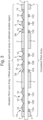
Figure 2 is a schematic, cross-section through the device shown inFigure 1 ; -
Figure 3 is a schematic, cross-section similar toFigure 2 but through a second embodiment for producing the effects shown inFigure 1 ; -
Figure 4 is a view similar toFigure 3 but showing a third, security thread embodiment for producing the effect shown inFigure 1 ; -
Figure 5A is a schematic, cross-section through a lenticular device for use in a comparative example; -
Figure 5B illustrates a cross-section through the comparative example; and, -
Figures 5C-5E illustrate the appearance of the comparative example at different viewing angles. -
Figures 1 and2 illustrate a banknote formed by a transparent ortranslucent polymer substrate 1, for example BOPP, on each side of which is provided a white, print receptive,opaque layer 2. Thelayers 2 are formed with rectangular, transparent viewing regions orwindows - Each viewing region is provided with a respective
lenticular device lenticular device 4A-6A comprises a one-dimensional array of parallel,cylindrical microlenses 10 formed in a conventional manner, for example by cast curing, on one side of thesubstrate 1 andparallel image strips substrate 1. The thickness of thesubstrate 1 is selected so that theimage strips 12A-12C are formed at the focus of thelenses 10. The microlenses typically have width dimensions in therange 5 to 200µm, more preferably 10 to 100µm and even more preferably 10 to 70µm. - It is important to note that the diagrams are not to scale and in reality there will be multiple repeats of the lens and images in each window.
- It will be noted that the
microlenses 10 are registered in the same manner in each of the windows with three microlenses being provided with an equal pitch. Each array ofimage strips 12A-12C, however, although defining the same pitch as themicrolenses 10, are offset by 1/3 of that pitch relative to the viewing region orwindow 4, in thewindow 5, and by a further 1/3 pitch offset in thewindow 6. - The
image strips 12A-12C located in thewindow 4 are chosen so that when thewindow 4 is viewed in adirection 20, corresponding to the "first" viewing angle of thedevice 4A, themicrolenses 10 will cause theimage strips 12A-12C, which define respective parts of the resultant image, to form that resultant image, in this case a letter X, which can be viewed by an observer holding the banknote at the appropriate angle, as shown inFigure 1A . - The
strips 12A-12C in thewindow 5 are identical to thestrips 12A-12C respectively in thewindow 4 but since they are offset with respect to thelenses 10 from their position in thewindow 4, the symbol X will be viewed only when thewindow 5 is observed at its own "first viewing angle" in thedirection 22. This is shown inFigure 1B . - With respect to the
window 6, again theimage strips 12A-12C are the same as those in thewindow 4 but due to the further offset relative to themicrolenses 10, the symbol X will only be seen when thelenticular device 6A is viewed at is own "first viewing angle" corresponding to thedirection 24. This is shown inFigure 1C . - When the banknote is viewed in the
direction 20, therefore, the letter X generated by thelenticular device 4A will be observed as shown inFigure 1A . However, since theviewing direction 20 does not correspond to thefirst viewing angle lenticular devices - When the
banknote 1 is viewed in thedirection 22, thelenticular device 5A will generate the letter X as seen inFigure 1B but since thedirection 22 is not the same as thedirection 20 or thedirection 24, thelenticular devices - Finally, when the
banknote 1 is viewed in the direction 24 (Figure 1C ), thelenticular device 6A will generate the symbol X but since thedirection 24 is not the same as thedirection lenticular devices - The observer will therefore be able to see very easily how the symbol X moves in sequence from the
window 4 to thewindow 5 and from thewindow 5 to thewindow 6 as the banknote is tilted. He thus observes the combination of variable regions defined by the windows 4-6 interspersed with static regions defined by the intermediate opacifying layers 2. - This makes the device easy to authenticate but yet difficult to fabricate.
-
Figure 3 illustrates a modified embodiment in which the printed image strips 12A-12C are printed in the same register within each of the windows 4-6 but themicrolenses 10, although being provided at the same pitch, are located with a 1/3 pitch offset in successive windows. The resultant effect is the same as in theFigure 2 embodiment and as shown inFigure 1 . - In the embodiments shown, the lenticular devices are viewed in transmitted light. However, it should be noted that in modifications of the above embodiments (not shown) the viewing region could comprise a half-window with the
opaque layer 2 continuing across all or part of the window over the image element array. In this case, the window will not be transparent and will be viewed in reflected light. The window may (or may not) still appear relatively translucent compared to its surroundings. It is possible that some of the viewing regions could be fully transparent windows and some be half-windows. - In the embodiments described above, the security device has been formed directly in a polymer-based banknote. The invention is also applicable to paper documents. In this scenario the viewing regions of the security device or article can be arranged as a series of patches on the surface of the base substrate of the security document, or can be visible in windows on the surface of the document substrate, e.g. in the form of a windowed security thread. Security threads are now present in many of the world's currencies as well as vouchers, passports, travellers' cheques and other documents. In many cases the thread is provided in a partially embedded or windowed fashion where the thread appears to weave in and out of the paper and is visible in windows in one or both surfaces of the base substrate. One method for producing paper with so-called windowed threads can be found in
EP-A-0059056 .EP-A-0860298 andWO-A-03095188 WO-A-2000/39391 - The invention is also applicable to security threads as, for example, shown in
Figure 4 . The construction of the security thread is similar to the construction of the polymer banknote described above and the same reference numerals will be used to designate the same features, where appropriate. Thus, the security thread shown inFigure 4 comprises apolymer substrate 1 which is transparent or translucent. An upper surface of thesubstrate 1 has a one-dimensional array of parallel,cylindrical microlenses 10 formed thereon, for example by cast curing. It will be noted that themicrolenses 10 are provided in the form of a regular array of constant pitch. - On the underside of the
substrate 1 are printed arrays of parallel image strips 112A-112D inregions region 5. These arrays are printed in register withcorresponding microlenses 10 and thus have the same pitch as the microlenses but with successive arrays of image strips being offset relative to the correspondingmicrolenses 10 by 1/3 of the pitch so as to define three differentlenticular devices respective viewing regions - The thickness of the
substrate 1 corresponds to the focal length of themicrolenses 10 so that the printed image strips are at the focus of the microlenses and as a result each array of image strips and corresponding array of microlenses will reconstruct a symbol, in this case the letter X, when viewed at the corresponding "first" viewingangle Figure 1 and2 example whereby when the security thread is viewed in thedirection 20, the symbol X will be seen only in theviewing region 4; when the security thread is viewed in thedirection 22, the symbol X will be viewed only in theviewing region 5; and when the security thread is viewed in thedirection 24, the symbol X will only be seen in theviewing region 6. - In this example, a further continuous
background print layer 60 is also provided. The symbols can then be seen against the colour of thatbackground 60. The presence of thecoloured background layer 60 enhances the contrast between the observed image and the adjacent region. - When the security thread is embedded in a paper substrate, the security thread can be registered with the windows in the paper substrate such that the variable regions will be defined by paper windows and the static regions by paper bridges. One method of registering a security thread in paper to expose a predetermined region in a substrate is disclosed in
EP1567714 . - It will be noted that in the embodiments described above, a switching effect occurs in which the symbol X is either seen in a viewing window or the viewing window displays no image at all.
- In comparative examples, each lenticular device generates a symbol or other character at each viewing angle. An example of a security device of this type is illustrated in
Figure 5 .Figure 5A shows the structure of a singlelenticular device 4B comprising a transparent or translucent,polymer substrate 1 of for example BOPP. On the upper surface of thesubstrate 1 is provided a one-dimensional array of three parallelcylindrical microlenses 10. On the opposite side of thesubstrate 1, under eachmicrolens 10, are printed respective sets of threeimage strips 30A-34A; 30B-34B; and 30C-34C. - The thickness of the
substrate 1 corresponds to the focal length of themicrolenses 10 so that the image strips are located at the focus of those microlenses. - The image strips 30A, 30B, 30C in combination with the
microlenses 10 will form a symbol X when the lenticular device is viewed in itsdirection 40. The image strips 32A, 32B, 32C will generate with the microlenses 10 a symbol Y when viewed in thedirection 42. The image strips 34A, 34B, 34C will generate in combination with the microlenses 10 a symbol Z when viewed in thedirection 44. - In the full security device shown in
Figure 5B , white, print receptiveopaque layers 2 are provided on each side of thepolymer substrate 1 defining rectangular viewing regions orwindows lenticular device 4B is located in thewindow 4. Furtherlenticular devices windows - The
lenticular device 5B is similar to thelenticular device 4B except that the order of the image strips in each array of three image strips has been changed as shown inFigure 5B . - The
lenticular device 6B is also similar to thelenticular device 4B except that the image strips have been ordered differently from both thelenticular device 4B anddevice 5B. - The result of this ordering of the image strips 30-34 is that when the security device is viewed in the
direction 40, the symbol X will be displayed in thewindow 4, the symbol Y in thewindow 5, and the symbol Z in the window 6 (Figure 5C ). - When the security device is viewed in the
direction 42, the symbol Z will be displayed in thewindow 4, the symbol X in thewindow 5, and the symbol Y in the window 6 (Figure 5D ). - When the security device is viewed in the
direction 44, the symbol Y will be seen in thewindow 4, the symbol Z in thewindow 5, and the symbol X in thewindow 6. - Thus, as the banknote is tilted so that it is viewed successively in the
directions Figure 5C-5E which leads to a particularly secure method of authenticating the device. - Although we have referred to viewing the banknote at particular angles, in practice, each "viewing angle" will typically comprise a range of viewing angles. However, the viewing angle or range of viewing angles at which an image is generated by each lenticular device image will be substantially non-overlapping with the corresponding viewing angle or range of viewing angles at the other lenticular devices.
- In an ideal situation, when we refer to viewing angles or viewing angle ranges that are substantially non-overlapping, the image or images viewable at each of those viewing angles or viewing angle ranges would be visible by itself without interference from the image visible at the other angle or range of viewing angles. Nevertheless, it is envisaged that there could be a transition from one image to the other as the device is tilted such that the viewing angles or ranges of viewing angles are not completely non-overlapping.
- It will also be noted that although the examples described all involve one-dimensional lenticular devices based on cylindrical lenses and image strips, the invention is equally applicable to two-dimensional lenticular devices formed by arrays of spherical microlenses and corresponding arrays of image pixels.
- According to aspects of the invention there may be provided security devices in accordance with the following numbered clauses:
-
Numbered clause 1. A security device comprising a plurality of viewing regions, each region including a lenticular device, the lenticular devices being constructed so that at different respective first viewing angles or first viewing angle ranges, the lenticular device in each viewing region generates substantially the same first image, the first viewing angles or first viewing angle ranges of the lenticular devices being substantially non-overlapping. -
Numbered clause 2. A security device according to numberedclause 1, wherein the lenticular devices are constructed so that when they are viewed at angles outside the first viewing angle or first viewing angle range then no image is generated. - Numbered clause 3. A security device according to numbered
clause 1, wherein the lenticular devices are constructed so that at different respective second viewing angles or second viewing angle ranges, the lenticular device in each viewing region generates substantially the same second image, different from the first image, wherein the second viewing angle or viewing angle range of each lenticular device does not, or does not substantially, overlap the first viewing angle or first viewing angle range of that device, the second viewing angles or second viewing angle ranges being substantially non-overlapping. -
Numbered clause 4. A security device according to numbered clause 3, wherein the first viewing angle or first viewing angle range of one lenticular device substantially corresponds to the second viewing angle or second viewing angle range respectively of another lenticular device. -
Numbered clause 5. A security device according to any of the preceding numbered clauses, wherein the first image generated by each lenticular device varies in one or more of colour, size and orientation from the first image generated by the or each other lenticular device. -
Numbered clause 6. A security device according to numberedclause 1, wherein each lenticular device is constructed to generate images at respectively different viewing angles, wherein when the security device is viewed at successive viewing angles each lenticular device displays one of a sequence of different images, the images in each sequence being the same but the sequences being arranged such that at each viewing angle or range of viewing angles, each lenticular device generates a different one of the images. -
Numbered clause 7. A security device comprising a plurality of viewing regions, each region including a lenticular device, the lenticular devices being constructed so that at respective, different viewing angles or viewing angle ranges, the lenticular device in only one of the viewing regions generates an image, the viewing angles or viewing angle ranges being substantially non-overlapping. - Numbered clause 8. A security device according to numbered
clause 7, wherein each image is substantially the same. - Numbered clause 9. A security device according to numbered clause 8, wherein each image varies in one or more of colour, size or orientation with respect to the other images.
- Numbered
clause 10. A security device according to numberedclause 7, wherein the images form a recognisable sequence, such as an animation. - Numbered clause 11. A security device according to any of the preceding numbered clauses, wherein each image comprises one of a symbol, alphanumeric character, logo, or pictorial element such as a portrait, animal or landscape.
- Numbered clause 12. A security device according to any of the preceding numbered clauses, wherein each lenticular device comprises an array of focusing elements; and one or more corresponding arrays of image elements located substantially at the focus of the focusing elements, the or each array of image elements cooperating with the array of focusing elements to generate a respective image when the device is viewed at a corresponding viewing angle.
- Numbered clause 13. A security device according to numbered clause 12, wherein the focusing elements comprise a one dimensional array of parallel cylindrical lenses and the image elements comprise parallel image strips.
- Numbered clause 14. A security device according to numbered clause 13, wherein the pitches of the arrays of lenses and of the image elements are the same but the registration of the arrays of image elements to the corresponding arrays of lenses varies between viewing regions.
- Numbered clause 15. A security device according to numbered clause 12, wherein the array of focusing elements is a two-dimensional array of spherical lenses and wherein the or each array of image elements is a two-dimensional array of image pixels.
- Numbered clause 16. A security device according to any of numbered clauses 12 to 15, wherein the focusing elements are registered in the same manner with the viewing regions.
- Numbered clause 17. A security device according to any of numbered clauses 12 to 16, wherein the image elements are registered in the same manner with the viewing regions.
- Numbered clause 18. A security device according to any of the preceding numbered clauses, wherein the viewing regions comprise transparent or translucent windows.
- Numbered clause 19. A security device according to any of the preceding numbered clauses, the security device being provided on a substrate such as a polymer or paper substrate.
- Numbered
clause 20. A security device according to numbered clause 19, wherein the substrate is part of a security article chosen from the group of banknotes, cheques, passports, identity cards, certificates of authenticity and fiscal stamps. - Numbered clause 21. A security device according to numbered clause 18, wherein the substrate is part of a security thread.
Claims (13)
- A security device comprising a plurality of viewing regions (4, 5, 6), each region including a lenticular device, wherein each lenticular device comprises an array of focusing elements (10); and one or more corresponding arrays of image elements (12A, 12B, 12C) located substantially at the focus of the focusing elements, the or each array of image elements (12A, 12B, 12C) cooperating with the array of focusing elements (10) to generate a respective image when the device is viewed at a corresponding viewing angle, the array of focusing elements (10) and array(s) of image elements (12A, 12B, 12C) being arranged so that at different respective first viewing angles or first viewing angle ranges, the lenticular device in each viewing region (4, 5, 6) generates substantially the same first image, the first viewing angles or first viewing angle ranges of the lenticular devices being substantially non-overlapping, and
wherein the lenticular devices are constructed so that when they are viewed at angles outside the first viewing angle or first viewing angle range then no image is generated. - A security device according to claim 1, wherein the first image generated by each lenticular device varies in one or more of colour, size and orientation from the first image generated by the or each other lenticular device.
- A security device according to any of the preceding claims, wherein each image comprises one of a symbol, alphanumeric character, logo, or pictorial element such as a portrait, animal or landscape.
- A security device according to any of the preceding claims, wherein the focusing elements (10) comprise a one dimensional array of parallel cylindrical lenses and the image elements comprise parallel image strips (12A, 12B, 12C).
- A security device according to claim 5, wherein the pitches of the arrays of lenses and of the image elements are the same but the registration of the arrays of image elements to the corresponding arrays of lenses varies between viewing regions.
- A security device according to claim any of the preceding claims, wherein the array of focusing elements (10) is a two-dimensional array of spherical lenses and wherein the or each array of image elements is a two-dimensional array of image pixels.
- A security device according to any of claims any of the preceding claims, wherein the focusing elements (10) are registered in the same manner with the viewing regions.
- A security device according to any of claims any of the preceding claims, wherein the image elements are registered in the same manner with the viewing regions.
- A security device according to any of the preceding claims, wherein the viewing regions comprise transparent or translucent windows.
- A security device according to any of the preceding claims, the device comprising three viewing regions.
- A security device according to any of the preceding claims, the security device being provided on a substrate (1) such as a polymer or paper substrate.
- A security device according to claim 11, wherein the substrate (1) is part of a security article chosen from the group of banknotes, cheques, passports, identity cards, certificates of authenticity and fiscal stamps.
- A security device according to claim 9, wherein the substrate (1) is part of a security thread.
Applications Claiming Priority (3)
| Application Number | Priority Date | Filing Date | Title |
|---|---|---|---|
| GBGB1517401.4A GB201517401D0 (en) | 2015-10-02 | 2015-10-02 | Security device |
| EP16777747.3A EP3356156B1 (en) | 2015-10-02 | 2016-09-27 | Security device |
| PCT/GB2016/053000 WO2017055827A2 (en) | 2015-10-02 | 2016-09-27 | Security device |
Related Parent Applications (1)
| Application Number | Title | Priority Date | Filing Date |
|---|---|---|---|
| EP16777747.3A Division EP3356156B1 (en) | 2015-10-02 | 2016-09-27 | Security device |
Publications (2)
| Publication Number | Publication Date |
|---|---|
| EP4516530A2 true EP4516530A2 (en) | 2025-03-05 |
| EP4516530A3 EP4516530A3 (en) | 2025-06-11 |
Family
ID=54605976
Family Applications (2)
| Application Number | Title | Priority Date | Filing Date |
|---|---|---|---|
| EP16777747.3A Active EP3356156B1 (en) | 2015-10-02 | 2016-09-27 | Security device |
| EP25151325.5A Pending EP4516530A3 (en) | 2015-10-02 | 2016-09-27 | Security device |
Family Applications Before (1)
| Application Number | Title | Priority Date | Filing Date |
|---|---|---|---|
| EP16777747.3A Active EP3356156B1 (en) | 2015-10-02 | 2016-09-27 | Security device |
Country Status (15)
| Country | Link |
|---|---|
| US (1) | US20190061407A1 (en) |
| EP (2) | EP3356156B1 (en) |
| CN (1) | CN108430792B (en) |
| AU (2) | AU2016330009B2 (en) |
| BR (1) | BR112018006236B1 (en) |
| CA (1) | CA3000615C (en) |
| CL (1) | CL2018000817A1 (en) |
| CO (1) | CO2018003868A2 (en) |
| GB (2) | GB201517401D0 (en) |
| MA (1) | MA43350A (en) |
| MX (2) | MX382387B (en) |
| MY (1) | MY193403A (en) |
| PL (1) | PL3356156T3 (en) |
| WO (1) | WO2017055827A2 (en) |
| ZA (1) | ZA201801582B (en) |
Families Citing this family (6)
| Publication number | Priority date | Publication date | Assignee | Title |
|---|---|---|---|---|
| JP7154279B2 (en) * | 2017-08-11 | 2022-10-17 | エフ・ホフマン-ラ・ロシュ・アクチェンゲゼルシャフト | Lenticular labels for medical devices |
| FR3075095B1 (en) * | 2017-12-14 | 2020-02-28 | Oberthur Fiduciaire Sas | ASSEMBLY OF A COMPLEX TRANSPARENCY DEVICE AND AT LEAST ONE MICRO-IMAGE NETWORK, AS WELL AS A SECURITY DOCUMENT COMPRISING SAME |
| AU2018100225A4 (en) | 2018-02-21 | 2018-03-22 | Ccl Secure Pty Ltd | Micro-imagery design integration |
| GB2580069B (en) * | 2018-12-20 | 2022-06-15 | De La Rue Int Ltd | Security documents and methods of manufacture thereof |
| AU2020279844B2 (en) | 2019-05-20 | 2025-07-31 | Crane & Co., Inc. | Use of nanoparticles to tune index of refraction of layers of a polymeric matrix to optimize microoptic (MO) focus |
| MX2021014788A (en) | 2019-06-14 | 2022-01-18 | Crane & Co Inc | MICROOPTIC SECURITY DEVICE WITH ABSOLUTE RECORDING. |
Citations (17)
| Publication number | Priority date | Publication date | Assignee | Title |
|---|---|---|---|---|
| EP0059056A1 (en) | 1981-02-19 | 1982-09-01 | Portals Limited | Method for making a fibrous sheet |
| US4892336A (en) | 1986-03-18 | 1990-01-09 | Gao Gesellschaft Fuer Automation Und Organisation Mbh | Antifalsification document having a security thread embedded therein and a method for producing the same |
| EP0860298A2 (en) | 1993-05-01 | 1998-08-26 | Giesecke & Devrient GmbH | Security paper |
| WO2000039391A1 (en) | 1998-12-29 | 2000-07-06 | De La Rue International Limited | Improvements in making paper |
| WO2003095188A2 (en) | 2002-05-09 | 2003-11-20 | De La Rue International Limited | Improvements in fibrous sheets |
| US6856462B1 (en) | 2002-03-05 | 2005-02-15 | Serigraph Inc. | Lenticular imaging system and method of manufacturing same |
| EP1567714A1 (en) | 2002-12-05 | 2005-08-31 | De La Rue International Limited | Insertion of an elongate element into a fibrous substrate |
| US20070063053A1 (en) | 2003-12-12 | 2007-03-22 | Matthias Bergmann | Data support with identifications written thereon by means of a laser beam and method for production thereof |
| US7808710B2 (en) | 2006-06-26 | 2010-10-05 | Ovd Kinegram Ag | Multilayer element comprising microlenses |
| WO2011051670A2 (en) | 2009-10-30 | 2011-05-05 | De La Rue International Limited | Security device |
| WO2011051669A1 (en) | 2009-10-30 | 2011-05-05 | De La Rue International Limited | Security device and method of manufacturing the same |
| WO2012027779A1 (en) | 2010-09-03 | 2012-03-08 | Securency International Pty Ltd | Optically variable device |
| WO2012153106A1 (en) | 2011-05-09 | 2012-11-15 | De La Rue International Limited | Security device |
| US20140103632A1 (en) | 2011-06-23 | 2014-04-17 | Arjowiggins Security | Security thread |
| WO2014184560A1 (en) | 2013-05-17 | 2014-11-20 | De La Rue International Limted | Security documents and methods of manufacture |
| WO2015011494A1 (en) | 2013-07-26 | 2015-01-29 | De La Rue International Limited | Security device and method of manufacture |
| WO2015011493A1 (en) | 2013-07-26 | 2015-01-29 | De La Rue International Limited | Security devices and methods of manufacture |
Family Cites Families (9)
| Publication number | Priority date | Publication date | Assignee | Title |
|---|---|---|---|---|
| KR101225311B1 (en) * | 2003-11-21 | 2013-01-22 | 비쥬얼 피직스 엘엘씨 | Micro-optic security and image presentation system |
| GB0400984D0 (en) * | 2004-01-16 | 2004-02-18 | Rue De Int Ltd | Security document with threads |
| GB0919112D0 (en) * | 2009-10-30 | 2009-12-16 | Rue De Int Ltd | Security device |
| DE102010048772A1 (en) * | 2010-10-13 | 2012-04-19 | Bundesdruckerei Gmbh | A method of producing a security document having a viewing angle dependent security feature and security document |
| CN103358808B (en) * | 2012-03-28 | 2015-12-16 | 中钞特种防伪科技有限公司 | A kind of optical anti-counterfeit element and use the product of this optical anti-counterfeit element |
| GB201208137D0 (en) * | 2012-05-10 | 2012-06-20 | Rue De Int Ltd | Security devices and methods of manufacture therefor |
| AU2012100985B4 (en) * | 2012-06-29 | 2012-11-15 | Ccl Secure Pty Ltd | Optically variable colour image |
| CN104118236B (en) * | 2014-07-10 | 2016-08-24 | 中钞特种防伪科技有限公司 | The micro-reflecting element array optical Security element of a kind of focusing and valuables |
| CN104191860B (en) * | 2014-08-27 | 2016-06-22 | 苏州大学 | Colored dynamic solid moir é pattern thin film based on micro-printing and preparation method thereof |
-
2015
- 2015-10-02 GB GBGB1517401.4A patent/GB201517401D0/en not_active Ceased
-
2016
- 2016-09-27 MY MYPI2018701294A patent/MY193403A/en unknown
- 2016-09-27 WO PCT/GB2016/053000 patent/WO2017055827A2/en not_active Ceased
- 2016-09-27 MX MX2018003889A patent/MX382387B/en unknown
- 2016-09-27 CN CN201680056742.3A patent/CN108430792B/en active Active
- 2016-09-27 PL PL16777747.3T patent/PL3356156T3/en unknown
- 2016-09-27 MA MA43350A patent/MA43350A/en unknown
- 2016-09-27 AU AU2016330009A patent/AU2016330009B2/en active Active
- 2016-09-27 US US15/765,299 patent/US20190061407A1/en not_active Abandoned
- 2016-09-27 MX MX2020011522A patent/MX2020011522A/en unknown
- 2016-09-27 CA CA3000615A patent/CA3000615C/en active Active
- 2016-09-27 BR BR112018006236-7A patent/BR112018006236B1/en active IP Right Grant
- 2016-09-27 GB GB1616352.9A patent/GB2544861B/en active Active
- 2016-09-27 EP EP16777747.3A patent/EP3356156B1/en active Active
- 2016-09-27 EP EP25151325.5A patent/EP4516530A3/en active Pending
-
2018
- 2018-03-07 ZA ZA2018/01582A patent/ZA201801582B/en unknown
- 2018-03-28 CL CL2018000817A patent/CL2018000817A1/en unknown
- 2018-04-11 CO CONC2018/0003868A patent/CO2018003868A2/en unknown
-
2022
- 2022-02-08 AU AU2022200816A patent/AU2022200816B2/en active Active
Patent Citations (17)
| Publication number | Priority date | Publication date | Assignee | Title |
|---|---|---|---|---|
| EP0059056A1 (en) | 1981-02-19 | 1982-09-01 | Portals Limited | Method for making a fibrous sheet |
| US4892336A (en) | 1986-03-18 | 1990-01-09 | Gao Gesellschaft Fuer Automation Und Organisation Mbh | Antifalsification document having a security thread embedded therein and a method for producing the same |
| EP0860298A2 (en) | 1993-05-01 | 1998-08-26 | Giesecke & Devrient GmbH | Security paper |
| WO2000039391A1 (en) | 1998-12-29 | 2000-07-06 | De La Rue International Limited | Improvements in making paper |
| US6856462B1 (en) | 2002-03-05 | 2005-02-15 | Serigraph Inc. | Lenticular imaging system and method of manufacturing same |
| WO2003095188A2 (en) | 2002-05-09 | 2003-11-20 | De La Rue International Limited | Improvements in fibrous sheets |
| EP1567714A1 (en) | 2002-12-05 | 2005-08-31 | De La Rue International Limited | Insertion of an elongate element into a fibrous substrate |
| US20070063053A1 (en) | 2003-12-12 | 2007-03-22 | Matthias Bergmann | Data support with identifications written thereon by means of a laser beam and method for production thereof |
| US7808710B2 (en) | 2006-06-26 | 2010-10-05 | Ovd Kinegram Ag | Multilayer element comprising microlenses |
| WO2011051670A2 (en) | 2009-10-30 | 2011-05-05 | De La Rue International Limited | Security device |
| WO2011051669A1 (en) | 2009-10-30 | 2011-05-05 | De La Rue International Limited | Security device and method of manufacturing the same |
| WO2012027779A1 (en) | 2010-09-03 | 2012-03-08 | Securency International Pty Ltd | Optically variable device |
| WO2012153106A1 (en) | 2011-05-09 | 2012-11-15 | De La Rue International Limited | Security device |
| US20140103632A1 (en) | 2011-06-23 | 2014-04-17 | Arjowiggins Security | Security thread |
| WO2014184560A1 (en) | 2013-05-17 | 2014-11-20 | De La Rue International Limted | Security documents and methods of manufacture |
| WO2015011494A1 (en) | 2013-07-26 | 2015-01-29 | De La Rue International Limited | Security device and method of manufacture |
| WO2015011493A1 (en) | 2013-07-26 | 2015-01-29 | De La Rue International Limited | Security devices and methods of manufacture |
Also Published As
| Publication number | Publication date |
|---|---|
| HK1258768A1 (en) | 2019-11-22 |
| EP4516530A3 (en) | 2025-06-11 |
| CO2018003868A2 (en) | 2018-07-10 |
| MA43350A (en) | 2018-08-08 |
| US20190061407A1 (en) | 2019-02-28 |
| WO2017055827A3 (en) | 2017-05-11 |
| AU2016330009B2 (en) | 2021-11-18 |
| GB2544861A (en) | 2017-05-31 |
| MX2018003889A (en) | 2018-12-10 |
| WO2017055827A2 (en) | 2017-04-06 |
| BR112018006236A2 (en) | 2018-10-09 |
| AU2016330009A2 (en) | 2018-07-19 |
| MX382387B (en) | 2025-03-13 |
| BR112018006236B1 (en) | 2022-08-16 |
| ZA201801582B (en) | 2019-07-31 |
| CA3000615A1 (en) | 2017-04-06 |
| PL3356156T3 (en) | 2025-03-24 |
| GB201616352D0 (en) | 2016-11-09 |
| CN108430792A (en) | 2018-08-21 |
| AU2022200816B2 (en) | 2024-01-11 |
| MY193403A (en) | 2022-10-11 |
| CN108430792B (en) | 2021-08-31 |
| EP3356156B1 (en) | 2025-01-29 |
| AU2022200816A1 (en) | 2022-02-24 |
| AU2016330009A1 (en) | 2018-04-12 |
| CL2018000817A1 (en) | 2018-10-12 |
| CA3000615C (en) | 2024-01-23 |
| GB2544861B (en) | 2020-03-25 |
| MX2020011522A (en) | 2022-11-15 |
| EP3356156C0 (en) | 2025-01-29 |
| EP3356156A2 (en) | 2018-08-08 |
| GB201517401D0 (en) | 2015-11-18 |
Similar Documents
| Publication | Publication Date | Title |
|---|---|---|
| AU2022200816B2 (en) | Security device | |
| US10093124B2 (en) | Security devices and methods of manufacture | |
| CN105636798B (en) | Safety device and manufacturing method | |
| AU2011293079B2 (en) | Multichannel optically variable device | |
| AU2017264749B2 (en) | Security device and method of manufacture | |
| US7429062B2 (en) | Anti-counterfeiting see-through moire security feature using frequency-varying patterns | |
| US20060129823A1 (en) | Security device | |
| HK1258768B (en) | Security device | |
| AU2018100183B4 (en) | Methods for multi-channel image interlacing | |
| RU2605074C1 (en) | Protective element for sheet printing product | |
| GB2568077A (en) | Security document and method of manufacture thereof | |
| AU2003269583C1 (en) | Security device | |
| AU2003269583B2 (en) | Security device |
Legal Events
| Date | Code | Title | Description |
|---|---|---|---|
| PUAI | Public reference made under article 153(3) epc to a published international application that has entered the european phase |
Free format text: ORIGINAL CODE: 0009012 |
|
| STAA | Information on the status of an ep patent application or granted ep patent |
Free format text: STATUS: REQUEST FOR EXAMINATION WAS MADE |
|
| 17P | Request for examination filed |
Effective date: 20250110 |
|
| AC | Divisional application: reference to earlier application |
Ref document number: 3356156 Country of ref document: EP Kind code of ref document: P |
|
| AK | Designated contracting states |
Kind code of ref document: A2 Designated state(s): AL AT BE BG CH CY CZ DE DK EE ES FI FR GB GR HR HU IE IS IT LI LT LU LV MC MK MT NL NO PL PT RO RS SE SI SK SM TR |
|
| REG | Reference to a national code |
Ref country code: DE Ref legal event code: R079 Free format text: PREVIOUS MAIN CLASS: B42D0025450000 Ipc: B42D0025300000 |
|
| PUAL | Search report despatched |
Free format text: ORIGINAL CODE: 0009013 |
|
| AK | Designated contracting states |
Kind code of ref document: A3 Designated state(s): AL AT BE BG CH CY CZ DE DK EE ES FI FR GB GR HR HU IE IS IT LI LT LU LV MC MK MT NL NO PL PT RO RS SE SI SK SM TR |
|
| RIC1 | Information provided on ipc code assigned before grant |
Ipc: B42D 25/45 20140101ALI20250502BHEP Ipc: B42D 25/425 20140101ALI20250502BHEP Ipc: B42D 25/355 20140101ALI20250502BHEP Ipc: B42D 25/351 20140101ALI20250502BHEP Ipc: B42D 25/342 20140101ALI20250502BHEP Ipc: B42D 25/324 20140101ALI20250502BHEP Ipc: B42D 25/30 20140101AFI20250502BHEP |