EP4516519A1 - Inkjet recording apparatus and inkjet recording method - Google Patents
Inkjet recording apparatus and inkjet recording method Download PDFInfo
- Publication number
- EP4516519A1 EP4516519A1 EP24196848.6A EP24196848A EP4516519A1 EP 4516519 A1 EP4516519 A1 EP 4516519A1 EP 24196848 A EP24196848 A EP 24196848A EP 4516519 A1 EP4516519 A1 EP 4516519A1
- Authority
- EP
- European Patent Office
- Prior art keywords
- recording medium
- ejection head
- inkjet recording
- recording apparatus
- liquid
- Prior art date
- Legal status (The legal status is an assumption and is not a legal conclusion. Google has not performed a legal analysis and makes no representation as to the accuracy of the status listed.)
- Pending
Links
Images



Classifications
-
- B—PERFORMING OPERATIONS; TRANSPORTING
- B41—PRINTING; LINING MACHINES; TYPEWRITERS; STAMPS
- B41J—TYPEWRITERS; SELECTIVE PRINTING MECHANISMS, i.e. MECHANISMS PRINTING OTHERWISE THAN FROM A FORME; CORRECTION OF TYPOGRAPHICAL ERRORS
- B41J11/00—Devices or arrangements of selective printing mechanisms, e.g. ink-jet printers or thermal printers, for supporting or handling copy material in sheet or web form
- B41J11/0095—Detecting means for copy material, e.g. for detecting or sensing presence of copy material or its leading or trailing end
-
- B—PERFORMING OPERATIONS; TRANSPORTING
- B41—PRINTING; LINING MACHINES; TYPEWRITERS; STAMPS
- B41J—TYPEWRITERS; SELECTIVE PRINTING MECHANISMS, i.e. MECHANISMS PRINTING OTHERWISE THAN FROM A FORME; CORRECTION OF TYPOGRAPHICAL ERRORS
- B41J11/00—Devices or arrangements of selective printing mechanisms, e.g. ink-jet printers or thermal printers, for supporting or handling copy material in sheet or web form
- B41J11/0015—Devices or arrangements of selective printing mechanisms, e.g. ink-jet printers or thermal printers, for supporting or handling copy material in sheet or web form for treating before, during or after printing or for uniform coating or laminating the copy material before or after printing
-
- B—PERFORMING OPERATIONS; TRANSPORTING
- B41—PRINTING; LINING MACHINES; TYPEWRITERS; STAMPS
- B41J—TYPEWRITERS; SELECTIVE PRINTING MECHANISMS, i.e. MECHANISMS PRINTING OTHERWISE THAN FROM A FORME; CORRECTION OF TYPOGRAPHICAL ERRORS
- B41J2/00—Typewriters or selective printing mechanisms characterised by the printing or marking process for which they are designed
- B41J2/005—Typewriters or selective printing mechanisms characterised by the printing or marking process for which they are designed characterised by bringing liquid or particles selectively into contact with a printing material
- B41J2/01—Ink jet
- B41J2/21—Ink jet for multi-colour printing
- B41J2/2107—Ink jet for multi-colour printing characterised by the ink properties
- B41J2/2114—Ejecting specialized liquids, e.g. transparent or processing liquids
- B41J2/2117—Ejecting white liquids
-
- B—PERFORMING OPERATIONS; TRANSPORTING
- B41—PRINTING; LINING MACHINES; TYPEWRITERS; STAMPS
- B41J—TYPEWRITERS; SELECTIVE PRINTING MECHANISMS, i.e. MECHANISMS PRINTING OTHERWISE THAN FROM A FORME; CORRECTION OF TYPOGRAPHICAL ERRORS
- B41J29/00—Details of, or accessories for, typewriters or selective printing mechanisms not otherwise provided for
- B41J29/38—Drives, motors, controls or automatic cut-off devices for the entire printing mechanism
- B41J29/387—Automatic cut-off devices
-
- B—PERFORMING OPERATIONS; TRANSPORTING
- B41—PRINTING; LINING MACHINES; TYPEWRITERS; STAMPS
- B41J—TYPEWRITERS; SELECTIVE PRINTING MECHANISMS, i.e. MECHANISMS PRINTING OTHERWISE THAN FROM A FORME; CORRECTION OF TYPOGRAPHICAL ERRORS
- B41J3/00—Typewriters or selective printing or marking mechanisms characterised by the purpose for which they are constructed
- B41J3/407—Typewriters or selective printing or marking mechanisms characterised by the purpose for which they are constructed for marking on special material
- B41J3/4078—Printing on textile
-
- D—TEXTILES; PAPER
- D06—TREATMENT OF TEXTILES OR THE LIKE; LAUNDERING; FLEXIBLE MATERIALS NOT OTHERWISE PROVIDED FOR
- D06P—DYEING OR PRINTING TEXTILES; DYEING LEATHER, FURS OR SOLID MACROMOLECULAR SUBSTANCES IN ANY FORM
- D06P5/00—Other features in dyeing or printing textiles, or dyeing leather, furs, or solid macromolecular substances in any form
- D06P5/30—Ink jet printing
-
- B—PERFORMING OPERATIONS; TRANSPORTING
- B41—PRINTING; LINING MACHINES; TYPEWRITERS; STAMPS
- B41J—TYPEWRITERS; SELECTIVE PRINTING MECHANISMS, i.e. MECHANISMS PRINTING OTHERWISE THAN FROM A FORME; CORRECTION OF TYPOGRAPHICAL ERRORS
- B41J11/00—Devices or arrangements of selective printing mechanisms, e.g. ink-jet printers or thermal printers, for supporting or handling copy material in sheet or web form
- B41J11/007—Conveyor belts or like feeding devices
Definitions
- the present invention relates to an inkjet recording apparatus and an inkjet recording method.
- inkjet recording apparatuses that record an image by ejecting ink onto a recording surface of a recording medium have been known.
- in-line inkjet recording apparatuses are known that eject a pretreatment liquid during conveyance of the recording medium.
- the recording medium may absorb and expand to cause lifting wrinkles. Then, when the head of the inkjet recording apparatus comes into contact with the lifting wrinkle, an image forming defect may occur.
- Japanese Unexamined Patent Publication No. 2015-110275 describes an inkjet recording apparatus in which a light interruption sensor is provided on an upstream side of a conveyance apparatus, and in a case where lifting of a recording medium is detected, image formation is temporarily interrupted and a warning is issued.
- the head for the post-treatment liquid may come into contact with the lifting wrinkles generated by the ejection of the ink.
- such a problem could not be suppressed.
- the present invention has been made in view of such circumstances. It is an object of the present invention to provide an inkjet recording apparatus and an inkjet recording method that can suppress failures caused by in-line application of a first liquid such as a pretreatment liquid.
- an inkjet recording apparatus includes a conveyor that conveys a recording medium; an image former that forms an image on the recording medium; and a detector that detects a state of the recording medium, wherein, the image former includes, a first ejection head that ejects a first liquid onto the recording medium, and a second ejection head that ejects a second liquid onto the recording medium, and the detector detects a state of the recording medium after the first liquid is ejected by the first ejection head and before the second liquid is ejected by the second ejection head.
- an inkjet recording method of an inkjet recording apparatus including, a first ejection head that ejects a first liquid onto a recording medium, and a second ejection head that ejects a second liquid onto the recording medium
- the inkjet recording method comprising: conveying the recording medium; forming an image on the recording medium; and detecting a state of the recording medium, wherein in the detecting, a state of the recording medium after the first liquid is ejected by the first ejection head and before the second liquid is ejected by the second ejection head is detected.
- FIG. 1 is a perspective view of the inkjet recording apparatus according to a first embodiment of the present invention.
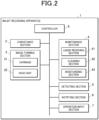
- FIG. 2 is a block diagram of the inkjet recording apparatus according to the first embodiment of the present invention.
- FIG. 3 is a side view of the inkjet recording apparatus 1.
- the inkjet recording apparatus 1 includes a conveyance section 2 (conveyor), an image forming section 3 (image former), a maintenance section 4, a detecting section 5 (detector), a notifying section 6 (notifier), an operation input section 7, and a controller 8 (hardware processor).
- FIG. 1 shows a configuration in which the maintenance section 4 is omitted for convenience.
- the conveyance section 2 conveys a recording medium M in the conveyance direction so as to pass below the image forming section 3.
- the conveyance section 2 includes, for example, two conveyance rollers 2a and 2b that rotate in the conveyance direction around rotation shafts extending in a widthwise direction. Furthermore, the conveyance section 2 includes a ring-shaped conveyance belt 2c.
- the inner side of the conveyance belt 2c is supported by the conveyance rollers 2a and 2b.
- an adhesive is applied to a conveyance surface of the conveyance belt 2c, which is a surface different from an inner surface that comes into contact with the conveyance rollers 2a and 2b and is an outer surface on a side on which the recording medium M is placed.
- the recording medium M is placed on the conveyance surface of the conveyance belt 2c.
- the conveyance rollers 2a and 2b rotate and circulate in the conveyance direction in accordance with an operation of a conveyance motor of the roller. As a result, the conveyance belt 2c conveys the recording medium M in the conveyance direction.
- the recording medium M is, for example, fabric.
- the recording medium M is supplied onto the conveyance belt 2c by a medium supply section (not shown).
- An image is recorded on the recording medium M by ink ejected from the image forming section 3.
- the recording medium M on which the image is recorded is discharged to a discharge section (not shown).
- the recording medium M is not limited to fabric.
- the recording medium M may be any recording medium on which landed ink can be fixed, and may be any of various media such as paper.
- the recording medium M is a fabric
- the fabric is a thin cloth having a thickness of 0.4 mm or less or a basis weight of 90 g/m2 or less, or if the fabric is made from cotton or polyester
- lifting wrinkles are likely to occur due to excessive application of the pre-treatment liquid described later.
- image formation failure occurs when the image is formed with the lifting wrinkle formed on the recording medium M, but the inkjet recording apparatus 1 according to the present embodiment can detect the lifting wrinkles before image formation.
- the image forming section 3 forms the image by ejecting the ink onto the recording medium M conveyed by the conveyance section 2 at an appropriate timing based on image data acquired from an external device or the like.
- FIG. 4 is a view of the image forming section 3 as seen from the height direction. As illustrated in FIG. 4 , the image forming section 3 includes a carriage 31 and a head unit 32.
- the carriage 31 is a member that moves the mounted head unit 32.
- the carriage 31 includes, for example, a belt bridged between two pulleys that are rotated by a motor (not illustrated).
- the carriage 31 causes the head unit 32 to scan in the width direction by a rotating operation of the motor based on a drive signal output by the controller 8.
- the pulley and the belt are extended further to the outside than a conveyance path along which the recording medium M is conveyed. Therefore, the carriage 31 is movable further outward than the conveyance path of the recording medium M.
- the inkjet recording apparatus 1 forms the image by ejecting the ink from the head unit 32 while allowing the carriage 31 to scan in the width direction, the carriage 31 being shorter than the recording medium M in length in the width direction.
- the inkjet recording apparatus 1 may employ a single-pass (one pass) method in which the image is formed by allowing the carriage 31 to scan once, or a multipass (scan) method in which an image of one line is formed by allowing the carriage 31 to scan a plurality of times.
- the head unit 32 is constituted by a plurality of inkjet heads.
- Each inkjet head includes an ink tank, a channel, a piezoelectric element, a plurality of nozzles, and the like. Under the control of the controller 8, the head unit 32 causes the piezoelectric element to apply pressure fluctuation to ink supplied from the tank to the nozzle via the channel, thereby ejecting the ink.
- the inkjet heads constituting the head unit 32 are a first ejection head 32a and a second ejection head 32b.
- the first ejection head 32a is an inkjet head that ejects a first liquid onto the recording medium M prior to the second ejection head 32b.
- the first liquid is the pretreatment liquid containing an aggregating agent.
- the first ejection head 32a is mounted on an upstream side in the conveyance direction relative to the second ejection head 32b.
- the pre-treatment liquid ejected from the first ejection head 32a is mixed in liquid form with the second liquid ejected from the second ejection head 32b on the recording medium M.
- the pretreatment liquid contains at least the aggregating agent.
- the pretreatment liquid may further contain other components such as a solvent, a surfactant, and water.
- the aggregating agent contained in the pretreatment liquid is not particularly limited as long as it generates an aggregate when coming into contact with the second liquid, and examples thereof include a polyvalent metal salt, an organic acid, and an inorganic acid.
- the second ejection head 32b ejects the second liquid after the first ejection head 32a ejects the pre-treatment liquid that is the first liquid.
- the second liquid is colored ink.
- the image forming section 3 may include a plurality of second ejection heads 32b.
- the plurality of second ejection heads 32b eject colored inks of, for example, C (cyan), M (magenta), Y (yellow), and K (black), respectively.
- the colored ink ejected by the second ejection head 32b is, for example, pigment ink.
- the pigment ink is an ink containing a pigment, resin particles (binder resin), and water.
- the pigment ink does not require heating treatment for dyeing and treatment for washing away undyed dye.
- FIG. 5 is a view of the inkjet recording apparatus 1 from a downstream side in the conveyance direction.
- the maintenance section 4 includes a liquid receiving section 41, a cleaning section 42, and a moisturizing section 43 on the outside in the width direction relative to the conveyance path of the recording medium M.
- the liquid receiving section 41 receives liquid (pre-treatment liquid and colored ink) ejected from the head unit 32.
- an absorber such as a sponge having hydrophilicity is stored.
- the liquid receiving section 41 discharges, from a discharge port provided in a bottom surface portion or the like, the liquid ejected and received from the head unit 32.
- the liquid receiving section 41 includes a discard tub 41a and a maintenance tub 41b.
- the discard tub 41a is provided closer to the conveyance path of the recording medium M than the maintenance tub 41b.
- the length of the discard tub 41a in the width direction is slightly larger than one nozzle row in one inkjet head.
- the controller 8 causes the discard tub 41a to execute a discarding ejection of the ink every time the carriage 31 scans.
- the control can prevent the liquids (the pretreatment liquid and the colored ink) in each inkjet head from drying and thickening in the nozzles.
- the discard tub 41a is provided only on one side in the widthwise direction of the inkjet recording apparatus 1
- the invention is not limited thereto.
- the discard tub 41a may be provided on both sides of the inkjet recording apparatus 1.
- the maintenance tub 41b is provided farther from the conveyance path of the recording medium M than the discard tub 41a.
- the maintenance tub 41b is provided so as to be slightly wider than the carriage 31 in the widthwise direction.
- the maintenance tub 41b is provided so as to have a larger volume than the discard tub 41a.
- the moisturizing section 43 is a container in which a predetermined liquid such as water is accommodated and the nozzle surface side of the image forming section 3 is opened. The liquid contained in the moisturizing section 43 is evaporated to humidify the nozzles of the head unit 32 when not in use, thereby preventing the nozzles from being clogged.
- the detecting section 5 detects a lifting wrinkle of the recording medium M during image formation by the image forming section 3.
- the light receiver 51b detects the light blocking, that is, the generation of the lifting wrinkle when the lifting of the recording medium M becomes equal to or more than a predetermined threshold value, for example, a length between the second ejection head 32b and the reference surface B, and the amount of light acquired from the light emitter 51a decreases by a predetermined value or more.
- the light receiver 51b that has detected the occurrence of the lifting wrinkle transmits a signal to the controller 8.
- the controller 8 Upon receiving the signal, the controller 8 causes the image forming section 3 to stop the image forming operation and causes the notifying section 6 to issue a warning.
- the reference surface B can be appropriately set in accordance with the thickness or the like of the recording medium M.
- the reference surface B is the front surface of the recording medium M, but is not limited thereto.
- the light emitter 51a and the light receiver 51b are arranged so that the discard tub 41a and the maintenance tub 41b are positioned under the optical axis.
- the light receiver 51b transmits the signal to the controller 8 not only when the lifting wrinkle appears in the recording medium M, but also when the recording medium M is shielded from light by the discard tub 41a or the maintenance tub 41b.
- the color ink and the pretreatment liquid may be mixed.
- the color ink and the pretreatment liquid may be aggregated in the discard tub 41a or the maintenance tub 41b to form the aggregate. Then, the aggregate that has reached the predetermined height and the head unit 32 may come into contact with each other, resulting in damage to the head unit 32.
- the controller 8 (hardware processor) includes a central processing unit (CPU), a random access memory (RAM), and a read only memory (ROM). Thus, the controller 8 controls the overall operation of the inkjet recording apparatus 1.
- CPU central processing unit
- RAM random access memory
- ROM read only memory
- the CPU controls each part of the inkjet recording apparatus 1.
- the RAM is a volatile memory that temporarily stores various kinds of information in a writable and readable manner.
- the ROM is a non-volatile memory in which various types of information and programs are stored in a readable manner. More specifically, the controller 8 causes the CPU to read a specified program from various programs stored in the ROM and load the program into the RAM. Then, the controller 8 executes various kinds of processing in coordination with the loaded program.
- the controller 8 functions as an image formation controller that controls whether to cause the image forming section 3 to form an image in accordance with a detection result of the detecting section 5.
- the controller 8 also functions as a notification controller that causes the notifying section 6 to issue the warning in accordance with the detection result of the detecting section 5.
- the controller 8 determines whether or not the detecting section 5 has detected lifting (light blocking) (step S101).
- the controller 8 serving as a notification controller causes the notifying section 6 to issue the warning (step S102).
- the controller 8 serving as the image forming controller causes the conveyance section 2 and the image forming section 3 to stop the image forming operation (step S103).
- the controller 8 determines whether an instruction to resume the image forming operation has been acquired (step S104). If the instruction to resume the image forming operation is acquired (step S 104; Yes), the controller 8 resumes the image forming operation (step S105), and transitions to step S101 to detect the lifting again.
- the controller 8 forms an image on the recording medium M by discharging ink from the second ejection head 32b while the carriage 31 performs scanning (step S106). After scanning by the carriage 31, the controller 8 causes the conveyance section 2 to convey the recording medium M by a predetermined amount (step S107).
- the controller 8 determines whether the image forming operation has been completed (step S108). In the case where the image forming operation is completed (Step S108; Yes), the controller 8 ends the image forming process. If the image forming operation has not been completed (step S108; No), the controller 8 transitions to step S101.
- the inkjet recording apparatus 1 includes the conveyance section 2 to convey the recording medium M.
- the inkjet recording apparatus 1 further includes an image forming section 3 to form the image on the recording medium M.
- the inkjet recording apparatus 1 further includes a detecting section 5 to detect the condition of the recording medium M.
- the image forming section 3 includes the first ejection head 32a that ejects the pretreatment liquid, which is the first liquid, onto the recording medium M.
- the image forming section 3 includes the second ejection head 32b that ejects ink, which is the second liquid, onto the recording medium M.
- the detecting section 5 detects the state of the recording medium M after the first ejection head 32a ejects the first liquid and before the second ejection head 32b ejects the second liquid.
- the state can be suppressed by the detecting section 5 sensing it.
- the detecting section 5 detects lifting of the recording medium M from the reference surface, it is possible to suppress occurrence of image formation failure on the recording medium M.
- the light interruption sensor which is the detecting section 5 includes only a pair of the light emitter 51a and the light receiver 51b
- the invention is not limited thereto. That is, the light interruption sensor including a plurality of sets of light emitters 51a and light receivers 51b corresponding to all the nozzle rows of the head unit 32 may be provided as the detecting section 5. With this configuration, it is possible to further suppress a defect caused by the application of the pretreatment liquid.
- FIG. 7 is a front view of the inkjet recording apparatus 1 according to the second embodiment.
- the inkjet recording apparatus 1 according to the second embodiment is different from the first embodiment in that a distance meter 52 which is the detecting section 5 is provided in the carriage 31.
- the inkjet recording apparatus 1 includes the distance meter 52 on each of both side surfaces of the carriage 31 in the width direction, respectively.
- the distance meter 52 measures the distance (height) from the second ejection head 32b to the recording medium M during image formation by the image forming section 3, and detects lifting of the recording medium M from the reference surface B based on the measured values.
- the distance meter 52 can adopt a known configuration, and for example, any of a laser beam type, an ultrasonic wave type, or an optical type can be adopted.
- the detecting section 5 includes the distance meter 52, it is possible to sense and suppress a state in which a problem due to application of the preprocessing liquid by the first ejection head 32a occurs.
- the inkjet recording apparatus 1 according to a third embodiment will be described. Note that elements that are the same as those of the inkjet recording apparatus 1 according to the first and second embodiments are denoted by the same reference numerals, and detailed description of those elements is omitted.
- the inkjet recording apparatus 1 according to the third embodiment is different from the first and second embodiments in that the first liquid ejected from the first ejection head 32a is a colored ink and the second liquid ejected from the second ejection head 32b is a post-treatment liquid.
- the post-treatment liquid ejected by the second ejection head 32b is, for example, a colorless coating ink. Even in a case where the first ejection head 32a ejects colored ink, the recording medium M may contract and expand to cause lifting wrinkles. Then, the second ejection head 32b comes into contact with the lifting wrinkle, and a failure such as breakage may occur.
- the detecting section 5 is provided which detects the state of the recording medium M after the ejection of the first liquid by the first ejection head 32a and before the second ejection head 32b ejects the second liquid. Therefore, in the inkjet recording apparatus 1 according to the third embodiment, even if a state in which a failure is caused due to ink application by the first ejection head 32a occurs, the state can be suppressed by sensing by the detecting section 5.
- the detecting section 5 may detect a lump of the first liquid or a fold on the recording medium M.
- the light interruption sensor and the distance sensor are exemplified, but a contact sensor or the like may be used.
- the inkjet recording apparatus 1 may convey the recording medium M by a so-called roll-to-roll method in which tension is applied to the wound recording medium M and the recording medium M is unwound and conveyed.
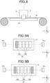
- FIG. 8 illustrates the case where the inkjet recording apparatus 1 includes a platen 2d, it is not limited thereto.
- the first ejection head 32a may be provided at a first end of the carriage 31 in the widthwise direction, and the second ejection head 32a may be provided at a position parallel to the first ejecting head 32b in the widthwise direction.
- the size of the carriage 31 can be reduced as compared with the configuration illustrated in FIG. 4A.
- the first liquid cannot be ejected before the second liquid is ejected when the carriage 31 scans in one direction (from left to right in FIG. 9A ), which reduces the producibility of the image forming process. Therefore, as illustrated in FIG. 9B , it is preferable to provide the first ejection head 32a on both ends of the carriage 31 in the widthwise direction.
- the second liquid discharged by the second ejection head 32b is color ink
- the invention is not limited thereto. That is, in the first and second embodiments, the second liquid may be not only color ink but also the pretreatment liquid, in particular, white ink.
- the white ink may be ejected from the second ejection head 32b on the upstream side in the conveyance direction or the width direction, and the color ink may be ejected from the second ejection head 32b on the downstream side.
- the serial type inkjet recording apparatus 1 which forms an image by scanning the carriage 31 of which the length in the width direction is shorter than the recording medium M in the width direction has been exemplified, but the invention is not limited thereto. That is, in the first and third embodiments, the inkjet recording apparatus 1 may be of a line system in which the head unit 32 having a length in the width direction longer than that of the recording medium M forms the image without scanning in the width direction.
- the display part may display, in real time, the lifting displacement of the recording medium M from the reference surface B acquired by the detecting section 5.
- the user performs the process related to the lifting wrinkles of the recording medium M or the aggregate in the liquid receiving section 41, and instructs the restart of the image forming operation by the operation input section 7, but the invention is not limited thereto. That is, it may be possible to adopt a configuration in which the inkjet recording apparatus 1 is provided with a mechanism capable of executing processing related to the lifting wrinkles of the recording medium M or aggregates in the liquid receiving section 41 and in which, through processing under the control of the controller 8, the image forming operation is automatically resumed when the detecting section 5 no longer detects the lifting.
Landscapes
- Engineering & Computer Science (AREA)
- Textile Engineering (AREA)
- Ink Jet (AREA)
Abstract
Description
- The present invention relates to an inkjet recording apparatus and an inkjet recording method.
- Conventionally, inkjet recording apparatuses that record an image by ejecting ink onto a recording surface of a recording medium have been known. In particular, in-line inkjet recording apparatuses are known that eject a pretreatment liquid during conveyance of the recording medium.
- However, as a result of ejecting an excessive amount of the pretreatment liquid onto the recording medium, the recording medium may absorb and expand to cause lifting wrinkles. Then, when the head of the inkjet recording apparatus comes into contact with the lifting wrinkle, an image forming defect may occur.
- Therefore, for example,
Japanese Unexamined Patent Publication No. 2015-110275 - However, in the inkjet recording apparatus of
Japanese Unexamined Patent Publication No. 2015-110275 - Similarly, in a case where the post-treatment liquid is ejected by the in-line method after the ink is ejected onto the recording medium, the head for the post-treatment liquid may come into contact with the lifting wrinkles generated by the ejection of the ink. However, in the inkjet recording apparatus of
Japanese Unexamined Patent Publication No. 2015-110275 - The present invention has been made in view of such circumstances. It is an object of the present invention to provide an inkjet recording apparatus and an inkjet recording method that can suppress failures caused by in-line application of a first liquid such as a pretreatment liquid.
- In order to solve the above problem, an inkjet recording apparatus includes a conveyor that conveys a recording medium; an image former that forms an image on the recording medium; and a detector that detects a state of the recording medium, wherein, the image former includes, a first ejection head that ejects a first liquid onto the recording medium, and a second ejection head that ejects a second liquid onto the recording medium, and the detector detects a state of the recording medium after the first liquid is ejected by the first ejection head and before the second liquid is ejected by the second ejection head.
- According to another aspect, an inkjet recording method of an inkjet recording apparatus, the inkjet recording apparatus including, a first ejection head that ejects a first liquid onto a recording medium, and a second ejection head that ejects a second liquid onto the recording medium, the inkjet recording method comprising: conveying the recording medium; forming an image on the recording medium; and detecting a state of the recording medium, wherein in the detecting, a state of the recording medium after the first liquid is ejected by the first ejection head and before the second liquid is ejected by the second ejection head is detected.
- The advantages and features provided by one or more embodiments of the invention will become more fully understood from the detailed description given hereinafter and the appended drawings which are given by way of illustration only, and thus are not intended as a definition of the limits of the present invention, and wherein:
-
FIG. 1 is a perspective view of an inkjet recording apparatus; -
FIG. 2 is a block diagram of the inkjet recording apparatus; -
FIG. 3 is a side view of the inkjet recording apparatus as viewed in a width direction; -
FIG. 4 is a plan view of an image forming section of the inkjet recording apparatus as viewed in a height direction; -
FIG. 5 is a plan view of the inkjet recording apparatus according to a first embodiment when viewed from a conveyance direction; -
FIG. 6 is a flowchart of image forming processing of the inkjet recording apparatus; -
FIG. 7 is a plan view of the inkjet recording apparatus according to a second embodiment as viewed from the conveyance direction; -
FIG. 8 is a side view of an inkjet recording apparatus according to a modification example as viewed in a width direction; -
FIG. 9A is a plan view of an inkjet recording apparatus according to a modification example as viewed in a height direction; and -
FIG. 9B is a plan view of an inkjet recording apparatus according to a modification example as viewed in a height direction. - Hereinafter, one or more embodiments of the present invention will be described with reference to the drawings. However, the scope of the invention is not limited to the disclosed embodiments.
- Hereinafter, an inkjet recording apparatus according to an embodiment of the present invention will be described in detail with reference to the drawings. However, the scope of the invention is not limited to the illustrated examples. In the following description, components having the same functions and configurations are denoted by the same reference numerals, and the description thereof will be omitted.
-
FIG. 1 is a perspective view of the inkjet recording apparatus according to a first embodiment of the present invention.FIG. 2 is a block diagram of the inkjet recording apparatus according to the first embodiment of the present invention.FIG. 3 is a side view of theinkjet recording apparatus 1. Theinkjet recording apparatus 1 includes a conveyance section 2 (conveyor), an image forming section 3 (image former), amaintenance section 4, a detecting section 5 (detector), a notifying section 6 (notifier), anoperation input section 7, and a controller 8 (hardware processor). - Note that hereinafter, an X direction, a Y direction, and a Z direction refer to the directions illustrated in
FIG. 1 . Furthermore, in the following description, the X direction, the Y direction, and the Z direction are referred to as a width direction, a conveyance direction, and a height direction, respectively.FIG. 1 shows a configuration in which themaintenance section 4 is omitted for convenience. - The
conveyance section 2 conveys a recording medium M in the conveyance direction so as to pass below theimage forming section 3. Theconveyance section 2 includes, for example, twoconveyance rollers conveyance section 2 includes a ring-shaped conveyance belt 2c. - The inner side of the
conveyance belt 2c is supported by theconveyance rollers conveyance belt 2c, which is a surface different from an inner surface that comes into contact with theconveyance rollers conveyance belt 2c. Theconveyance rollers conveyance belt 2c conveys the recording medium M in the conveyance direction. - The recording medium M is, for example, fabric. The recording medium M is supplied onto the
conveyance belt 2c by a medium supply section (not shown). An image is recorded on the recording medium M by ink ejected from theimage forming section 3. The recording medium M on which the image is recorded is discharged to a discharge section (not shown). Note that the recording medium M is not limited to fabric. The recording medium M may be any recording medium on which landed ink can be fixed, and may be any of various media such as paper. - In the case where the recording medium M is a fabric, if the fabric is a thin cloth having a thickness of 0.4 mm or less or a basis weight of 90 g/m2 or less, or if the fabric is made from cotton or polyester, lifting wrinkles are likely to occur due to excessive application of the pre-treatment liquid described later. Usually, image formation failure occurs when the image is formed with the lifting wrinkle formed on the recording medium M, but the
inkjet recording apparatus 1 according to the present embodiment can detect the lifting wrinkles before image formation. - The
image forming section 3 forms the image by ejecting the ink onto the recording medium M conveyed by theconveyance section 2 at an appropriate timing based on image data acquired from an external device or the like.FIG. 4 is a view of theimage forming section 3 as seen from the height direction. As illustrated inFIG. 4 , theimage forming section 3 includes acarriage 31 and ahead unit 32. - The
carriage 31 is a member that moves the mountedhead unit 32. Thecarriage 31 includes, for example, a belt bridged between two pulleys that are rotated by a motor (not illustrated). Thecarriage 31 causes thehead unit 32 to scan in the width direction by a rotating operation of the motor based on a drive signal output by thecontroller 8. Furthermore, the pulley and the belt are extended further to the outside than a conveyance path along which the recording medium M is conveyed. Therefore, thecarriage 31 is movable further outward than the conveyance path of the recording medium M. - The
inkjet recording apparatus 1 according to the present embodiment forms the image by ejecting the ink from thehead unit 32 while allowing thecarriage 31 to scan in the width direction, thecarriage 31 being shorter than the recording medium M in length in the width direction. Theinkjet recording apparatus 1 may employ a single-pass (one pass) method in which the image is formed by allowing thecarriage 31 to scan once, or a multipass (scan) method in which an image of one line is formed by allowing thecarriage 31 to scan a plurality of times. - The
head unit 32 is constituted by a plurality of inkjet heads. Each inkjet head includes an ink tank, a channel, a piezoelectric element, a plurality of nozzles, and the like. Under the control of thecontroller 8, thehead unit 32 causes the piezoelectric element to apply pressure fluctuation to ink supplied from the tank to the nozzle via the channel, thereby ejecting the ink. The inkjet heads constituting thehead unit 32 are afirst ejection head 32a and asecond ejection head 32b. - The
first ejection head 32a is an inkjet head that ejects a first liquid onto the recording medium M prior to thesecond ejection head 32b. In the present embodiment, the first liquid is the pretreatment liquid containing an aggregating agent. As illustrated inFIG. 4 , in thecarriage 31, thefirst ejection head 32a is mounted on an upstream side in the conveyance direction relative to thesecond ejection head 32b. - The pre-treatment liquid ejected from the
first ejection head 32a is mixed in liquid form with the second liquid ejected from thesecond ejection head 32b on the recording medium M. The pretreatment liquid contains at least the aggregating agent. The pretreatment liquid may further contain other components such as a solvent, a surfactant, and water. The aggregating agent contained in the pretreatment liquid is not particularly limited as long as it generates an aggregate when coming into contact with the second liquid, and examples thereof include a polyvalent metal salt, an organic acid, and an inorganic acid. - The
second ejection head 32b ejects the second liquid after thefirst ejection head 32a ejects the pre-treatment liquid that is the first liquid. In the present embodiment, the second liquid is colored ink. As illustrated inFIG. 4 , theimage forming section 3 may include a plurality of second ejection heads 32b. The plurality of second ejection heads 32b eject colored inks of, for example, C (cyan), M (magenta), Y (yellow), and K (black), respectively. - The colored ink ejected by the
second ejection head 32b is, for example, pigment ink. The pigment ink is an ink containing a pigment, resin particles (binder resin), and water. When the pigment ink is applied to the recording medium M on which the pretreatment liquid has been applied, the components contained in the pigment ink do not penetrate into the recording medium M, the color developability increases, and the texture is less likely to be impaired. In addition, unlike dye ink, the pigment ink does not require heating treatment for dyeing and treatment for washing away undyed dye. -
FIG. 5 is a view of theinkjet recording apparatus 1 from a downstream side in the conveyance direction. Themaintenance section 4 includes aliquid receiving section 41, acleaning section 42, and amoisturizing section 43 on the outside in the width direction relative to the conveyance path of the recording medium M. - The
liquid receiving section 41 receives liquid (pre-treatment liquid and colored ink) ejected from thehead unit 32. In theliquid receiving section 41, an absorber such as a sponge having hydrophilicity is stored. Theliquid receiving section 41 discharges, from a discharge port provided in a bottom surface portion or the like, the liquid ejected and received from thehead unit 32. Theliquid receiving section 41 includes a discardtub 41a and amaintenance tub 41b. - The discard
tub 41a is provided closer to the conveyance path of the recording medium M than themaintenance tub 41b. The length of the discardtub 41a in the width direction is slightly larger than one nozzle row in one inkjet head. - The
controller 8 causes the discardtub 41a to execute a discarding ejection of the ink every time thecarriage 31 scans. The control can prevent the liquids (the pretreatment liquid and the colored ink) in each inkjet head from drying and thickening in the nozzles. - In
FIG. 5 , a configuration in which the discardtub 41a is provided only on one side in the widthwise direction of theinkjet recording apparatus 1 is exemplified, but the invention is not limited thereto. For example, in a case of a configuration in which the image is formed not only when thecarriage 31 is caused to perform scanning from one width-direction side to the opposite width-direction side but also when thecarriage 31 is caused to perform scanning from the other width-direction side to the one width-direction side, the discardtub 41a may be provided on both sides of theinkjet recording apparatus 1. - The
maintenance tub 41b is provided farther from the conveyance path of the recording medium M than the discardtub 41a. Themaintenance tub 41b is provided so as to be slightly wider than thecarriage 31 in the widthwise direction. - In a case where normal pressure is not applied to the ink and the ink is not ejected from the nozzles of each inkjet head and an image defect occurs (in a case where a so-called nozzle clogging phenomenon occurs), the
controller 8 conveys thecarriage 31 above themaintenance tub 41b and causes purging to be executed. Specifically, in order to eject foreign matters, air bubbles, aggregates, and the like in each inkjet head to the outside, thecontroller 8 increases the supply pressure of the ink to each inkjet head to forcibly eject the ink. - Note that the amount of ink ejected by purging is greater than the amount of ink ejected by discard ejection. Therefore, as shown in
FIG. 5 , themaintenance tub 41b is provided so as to have a larger volume than the discardtub 41a. - The
cleaning section 42 is provided in the vicinity of themaintenance tub 41b, and wipes an ink ejection face of thehead unit 32 after purging with a wiping cloth or the like. Thecleaning section 42 includes a wiping cloth and a moving mechanism that moves the wiping cloth along the ink ejection face of thehead unit 32. The wiping operation of thecleaning section 42 can remove ink, foreign matter, and the like adhered to the ink ejection face of thehead unit 32 during purging. - The
moisturizing section 43 is a container in which a predetermined liquid such as water is accommodated and the nozzle surface side of theimage forming section 3 is opened. The liquid contained in themoisturizing section 43 is evaporated to humidify the nozzles of thehead unit 32 when not in use, thereby preventing the nozzles from being clogged. - The detecting
section 5 detects a state of the recording medium M, in particular, lifting of the recording medium M from a reference surface B. The detectingsection 5 is, for example, a light interruption sensor. The detectingsection 5 includes alight emitter 51a and alight receiver 51b. Thelight emitter 51a emits a linear laser beam having a predetermined width in a height direction. Thelight receiver 51b receives the laser beam emitted by thelight emitter 51a. - As shown in
FIG. 5 , thelight emitter 51a and thelight receiver 51b are provided outside theconveyance section 2 in the widthwise direction and outside a printing scanning range in which thecarriage 31 moves during image formation. Thelight receiver 51b is arranged on an optical axis of thelight emitter 51a so as to be parallel to the width direction. To be more specific, as shown inFIG. 4 , thelight emitter 51a and thelight receiver 51b are arranged on the downstream side of thefirst ejection head 32a in the conveyance direction so that the optical axis is positioned on a straight line parallel to the nozzle row of thesecond ejection head 32b. Therefore, the detectingsection 5 can detect the lifting of the recording medium M after thefirst ejection head 32a ejects the pretreatment liquid that is the first liquid and before thesecond ejection head 32b ejects the second liquid. - The detecting
section 5 detects a lifting wrinkle of the recording medium M during image formation by theimage forming section 3. To be specific, thelight receiver 51b detects the light blocking, that is, the generation of the lifting wrinkle when the lifting of the recording medium M becomes equal to or more than a predetermined threshold value, for example, a length between thesecond ejection head 32b and the reference surface B, and the amount of light acquired from thelight emitter 51a decreases by a predetermined value or more. Thelight receiver 51b that has detected the occurrence of the lifting wrinkle transmits a signal to thecontroller 8. Upon receiving the signal, thecontroller 8 causes theimage forming section 3 to stop the image forming operation and causes the notifyingsection 6 to issue a warning. - Note that the position of the detecting
section 5 in the height direction is adjustable. Therefore, the reference surface B can be appropriately set in accordance with the thickness or the like of the recording medium M. InFIG. 5 , the reference surface B is the front surface of the recording medium M, but is not limited thereto. - Further, in the present embodiment, as shown in
FIG. 5 , thelight emitter 51a and thelight receiver 51b are arranged so that the discardtub 41a and themaintenance tub 41b are positioned under the optical axis. With the above-described configuration, thelight receiver 51b transmits the signal to thecontroller 8 not only when the lifting wrinkle appears in the recording medium M, but also when the recording medium M is shielded from light by the discardtub 41a or themaintenance tub 41b. - When the discharge port of the discard
tub 41a or themaintenance tub 41b is clogged, the color ink and the pretreatment liquid may be mixed. In this case, the color ink and the pretreatment liquid may be aggregated in the discardtub 41a or themaintenance tub 41b to form the aggregate. Then, the aggregate that has reached the predetermined height and thehead unit 32 may come into contact with each other, resulting in damage to thehead unit 32. - However, with the above-described arrangement, the
light receiver 51b transmits the signal to thecontroller 8 also in a case where the height of the aggregate in the discardtub 41a or themaintenance tub 41b is, for example, greater than or equal to the distance between thesecond ejection head 32b and the discardtub 41a or themaintenance tub 41b. Therefore, damage to thehead unit 32 due to contact between the aggregate and thehead unit 32 can be prevented. - The notifying
section 6 provides notification of various information under the control of thecontroller 8. The notifyingsection 6 is, for example, a display part having a screen, a sound emitting section that emits a predetermined sound, a communication section that can communicate with another device via a network, or the like. - The
operation input section 7 is composed of, for example, various operation keys and the like, converts a user's input operation into an operation signal, and outputs the operation signal to thecontroller 8. Note that when the notifyingsection 6 is a display part, theoperation input section 7 may be a touch screen. - The controller 8 (hardware processor) includes a central processing unit (CPU), a random access memory (RAM), and a read only memory (ROM). Thus, the
controller 8 controls the overall operation of theinkjet recording apparatus 1. - The CPU controls each part of the
inkjet recording apparatus 1. The RAM is a volatile memory that temporarily stores various kinds of information in a writable and readable manner. The ROM is a non-volatile memory in which various types of information and programs are stored in a readable manner. More specifically, thecontroller 8 causes the CPU to read a specified program from various programs stored in the ROM and load the program into the RAM. Then, thecontroller 8 executes various kinds of processing in coordination with the loaded program. - In particular, the
controller 8 functions as an image formation controller that controls whether to cause theimage forming section 3 to form an image in accordance with a detection result of the detectingsection 5. Thecontroller 8 also functions as a notification controller that causes the notifyingsection 6 to issue the warning in accordance with the detection result of the detectingsection 5. - Image forming processing in such an
inkjet recording apparatus 1 will be described with reference to the flowchart ofFIG. 6 . - First, the
controller 8 determines whether or not the detectingsection 5 has detected lifting (light blocking) (step S101). When the detectingsection 5 detects lifting (step S101; Yes), thecontroller 8 serving as a notification controller causes the notifyingsection 6 to issue the warning (step S102). Further, thecontroller 8 serving as the image forming controller causes theconveyance section 2 and theimage forming section 3 to stop the image forming operation (step S103). - Upon being notified by the notifying
section 6, the user smooths out and corrects the lifting wrinkle generated on the recording medium M. Alternatively, the recording medium M is manually conveyed to evacuate the lifting wrinkle to the outside of the printing region. Then, the user adjusts the amount of the pretreatment liquid to be ejected by thefirst ejection head 32a to be small. Alternatively, the user cleans the discardtub 41a or themaintenance tub 41b. When the processing relating to the lifting wrinkles of the recording medium M or the aggregate in theliquid receiving section 41 is finished, the user transmits an instruction to resume the image forming operation to thecontroller 8 by operating theoperation input section 7. - The
controller 8 determines whether an instruction to resume the image forming operation has been acquired (step S104). If the instruction to resume the image forming operation is acquired (step S 104; Yes), thecontroller 8 resumes the image forming operation (step S105), and transitions to step S101 to detect the lifting again. - In a case where the detecting
section 5 does not detect lifting (step S101; No), thecontroller 8 forms an image on the recording medium M by discharging ink from thesecond ejection head 32b while thecarriage 31 performs scanning (step S106). After scanning by thecarriage 31, thecontroller 8 causes theconveyance section 2 to convey the recording medium M by a predetermined amount (step S107). - The
controller 8 determines whether the image forming operation has been completed (step S108). In the case where the image forming operation is completed (Step S108; Yes), thecontroller 8 ends the image forming process. If the image forming operation has not been completed (step S108; No), thecontroller 8 transitions to step S101. - As described above, the
inkjet recording apparatus 1 according to the present embodiment includes theconveyance section 2 to convey the recording medium M. Theinkjet recording apparatus 1 further includes animage forming section 3 to form the image on the recording medium M. Theinkjet recording apparatus 1 further includes a detectingsection 5 to detect the condition of the recording medium M. Theimage forming section 3 includes thefirst ejection head 32a that ejects the pretreatment liquid, which is the first liquid, onto the recording medium M. Furthermore, theimage forming section 3 includes thesecond ejection head 32b that ejects ink, which is the second liquid, onto the recording medium M. Then, the detectingsection 5 detects the state of the recording medium M after thefirst ejection head 32a ejects the first liquid and before thesecond ejection head 32b ejects the second liquid. - With this structure, even if a state occurs in which a failure is caused by the application of the pretreatment liquid by the
first ejection head 32a, the state can be suppressed by the detectingsection 5 sensing it. In particular, since the detectingsection 5 detects lifting of the recording medium M from the reference surface, it is possible to suppress occurrence of image formation failure on the recording medium M. - In the above description, a configuration in which the light interruption sensor which is the detecting
section 5 includes only a pair of thelight emitter 51a and thelight receiver 51b is exemplified, but the invention is not limited thereto. That is, the light interruption sensor including a plurality of sets oflight emitters 51a andlight receivers 51b corresponding to all the nozzle rows of thehead unit 32 may be provided as the detectingsection 5. With this configuration, it is possible to further suppress a defect caused by the application of the pretreatment liquid. - Next, an
inkjet recording apparatus 1 according to a second embodiment will be described. The same symbols are used for the same configuration as that of theinkjet recording apparatus 1 of the first embodiment, and the detailed description is omitted.FIG. 7 is a front view of theinkjet recording apparatus 1 according to the second embodiment. Theinkjet recording apparatus 1 according to the second embodiment is different from the first embodiment in that adistance meter 52 which is the detectingsection 5 is provided in thecarriage 31. - As illustrated in
FIG. 7 , theinkjet recording apparatus 1 according to the second embodiment includes thedistance meter 52 on each of both side surfaces of thecarriage 31 in the width direction, respectively. Thedistance meter 52 measures the distance (height) from thesecond ejection head 32b to the recording medium M during image formation by theimage forming section 3, and detects lifting of the recording medium M from the reference surface B based on the measured values. Thedistance meter 52 can adopt a known configuration, and for example, any of a laser beam type, an ultrasonic wave type, or an optical type can be adopted. - As described above, even in a case where the detecting
section 5 includes thedistance meter 52, it is possible to sense and suppress a state in which a problem due to application of the preprocessing liquid by thefirst ejection head 32a occurs. - Next, the
inkjet recording apparatus 1 according to a third embodiment will be described. Note that elements that are the same as those of theinkjet recording apparatus 1 according to the first and second embodiments are denoted by the same reference numerals, and detailed description of those elements is omitted. Theinkjet recording apparatus 1 according to the third embodiment is different from the first and second embodiments in that the first liquid ejected from thefirst ejection head 32a is a colored ink and the second liquid ejected from thesecond ejection head 32b is a post-treatment liquid. - In the
inkjet recording apparatus 1 according to the third embodiment, the post-treatment liquid ejected by thesecond ejection head 32b is, for example, a colorless coating ink. Even in a case where thefirst ejection head 32a ejects colored ink, the recording medium M may contract and expand to cause lifting wrinkles. Then, thesecond ejection head 32b comes into contact with the lifting wrinkle, and a failure such as breakage may occur. - However, in the present invention, as described above, the detecting
section 5 is provided which detects the state of the recording medium M after the ejection of the first liquid by thefirst ejection head 32a and before thesecond ejection head 32b ejects the second liquid. Therefore, in theinkjet recording apparatus 1 according to the third embodiment, even if a state in which a failure is caused due to ink application by thefirst ejection head 32a occurs, the state can be suppressed by sensing by the detectingsection 5. - Although specific description has been given above based on the embodiment according to the present invention, the present invention is not limited to the above-described embodiment. It is a matter of course that the present invention can be subjected to various modifications within the scope of the invention described in the claims and the equivalents thereof.
- For example, in the above description, a configuration in which the detecting
section 5 detects lifting of the recording medium M has been exemplified, but the invention is not limited thereto. For example, the detectingsection 5 may detect a lump of the first liquid or a fold on the recording medium M. In addition, as the detectingsection 5, the light interruption sensor and the distance sensor are exemplified, but a contact sensor or the like may be used. - In addition, in the above description, as shown in
FIG. 3 , a configuration in which theinkjet recording apparatus 1 includes theconveyance section 2 and transports the recording medium M by a belt transport method is exemplified, but the invention is not limited thereto. That is, as illustrated inFIG. 8 , theinkjet recording apparatus 1 may convey the recording medium M by a so-called roll-to-roll method in which tension is applied to the wound recording medium M and the recording medium M is unwound and conveyed. Note that althoughFIG. 8 illustrates the case where theinkjet recording apparatus 1 includes aplaten 2d, it is not limited thereto. - In addition, in the above description, as shown in
FIG. 4 , a configuration in which thefirst ejection head 32a is provided on the upstream side of thesecond ejection head 32b in the conveyance direction in thecarriage 31 is exemplified, but the invention is not limited thereto. - As illustrated in
FIG. 9A , thefirst ejection head 32a may be provided at a first end of thecarriage 31 in the widthwise direction, and thesecond ejection head 32a may be provided at a position parallel to thefirst ejecting head 32b in the widthwise direction. With the above-described configuration, the size of thecarriage 31 can be reduced as compared with the configuration illustrated in FIG. 4A. In the above-described configuration, the first liquid cannot be ejected before the second liquid is ejected when thecarriage 31 scans in one direction (from left to right inFIG. 9A ), which reduces the producibility of the image forming process. Therefore, as illustrated inFIG. 9B , it is preferable to provide thefirst ejection head 32a on both ends of thecarriage 31 in the widthwise direction. - In addition, in the above description, a configuration in which the second liquid discharged by the
second ejection head 32b is color ink is exemplified, but the invention is not limited thereto. That is, in the first and second embodiments, the second liquid may be not only color ink but also the pretreatment liquid, in particular, white ink. - Specifically, after the pretreatment liquid containing the aggregation agent is ejected from the
first ejection head 32a, the white ink may be ejected from thesecond ejection head 32b on the upstream side in the conveyance direction or the width direction, and the color ink may be ejected from thesecond ejection head 32b on the downstream side. - In addition, in the above description, the serial type
inkjet recording apparatus 1 which forms an image by scanning thecarriage 31 of which the length in the width direction is shorter than the recording medium M in the width direction has been exemplified, but the invention is not limited thereto. That is, in the first and third embodiments, theinkjet recording apparatus 1 may be of a line system in which thehead unit 32 having a length in the width direction longer than that of the recording medium M forms the image without scanning in the width direction. - Furthermore, in a case where the notifying
section 6 includes a display part, the display part may display, in real time, the lifting displacement of the recording medium M from the reference surface B acquired by the detectingsection 5. - In addition, in the image forming process, after the image forming operation is stopped in step S103, the user performs the process related to the lifting wrinkles of the recording medium M or the aggregate in the
liquid receiving section 41, and instructs the restart of the image forming operation by theoperation input section 7, but the invention is not limited thereto. That is, it may be possible to adopt a configuration in which theinkjet recording apparatus 1 is provided with a mechanism capable of executing processing related to the lifting wrinkles of the recording medium M or aggregates in theliquid receiving section 41 and in which, through processing under the control of thecontroller 8, the image forming operation is automatically resumed when the detectingsection 5 no longer detects the lifting. - Although embodiments of the present invention have been described and illustrated in detail, the disclosed embodiments are made for purposes of illustration and example only and not limitation. The scope of the present invention should be interpreted by terms of the appended claims.
Claims (15)
- An inkjet recording apparatus comprising:a conveyor that conveys a recording medium;an image former that forms an image on the recording medium; anda detector that detects a state of the recording medium,wherein,the image former includes, a first ejection head that ejects a first liquid onto the recording medium, and a second ejection head that ejects a second liquid onto the recording medium, andthe detector detects a state of the recording medium after the first liquid is ejected by the first ejection head and before the second liquid is ejected by the second ejection head.
- The inkjet recording apparatus according to claim 1, wherein the first liquid is a pretreatment liquid and the second liquid is ink.
- The inkjet recording apparatus according to claim 1, wherein the detector detects lifting of the recording medium from a reference surface.
- The inkjet recording apparatus according to claim 3, further comprising a carriage that conveys the first ejection head and the second ejection head in a width direction orthogonal to a conveyance direction of the recording medium.
- The inkjet recording apparatus according to claim 3, wherein,the detector is a light interruption sensor,the light interruption sensor includes a light emitter and a light receiver on each outer side of the conveyor in a width direction orthogonal to a conveyance direction of the recording medium, andthe light emitter and the light receiver have optical axes arranged in the width direction, and detect lifting of the recording medium from the reference surface.
- The inkjet recording apparatus according to claim 5, wherein the light emitter emits a line-shaped laser beam having a width in a height direction perpendicular to the conveyance direction and the width direction.
- The inkjet recording apparatus according to claim 4, wherein,the detector is a distance meter,the distance meter is provided on each of both side surfaces of the carriage in the width direction, andthe distance meter measures a distance between the recording medium and the second ejection head to detect the lifting of the recording medium from the reference surface.
- The inkjet recording apparatus according to claim 3, further comprising,a notifier that notifies a warning, anda hardware processor that, in a case in which the detector detects the lifting of the recording medium from the reference surface, causes the image former to stop forming the image and causes the notifier to notify the warning.
- The inkjet recording apparatus according to claim 8, wherein,the notifier includes a display that displays a displacement of the lifting of the recording medium from the reference surface, andthe detector detects, in real time, the displacement of the lifting of the recording medium from the reference surface.
- The inkjet recording apparatus according to claim 3, wherein,the first ejection head is mounted on an upstream side of the second ejection head in a conveyance direction of the recording medium, andthe detector is provided on a downstream side of the first ejection head in the conveyance direction .
- The inkjet recording apparatus according to claim 4, wherein,the first ejection head and the second ejection head are mounted substantially parallel to the width direction of the carriage, andthe detector is provided on a straight line parallel to a nozzle row of the second ejection head.
- The inkjet recording apparatus according to claim 3, wherein the recording medium is a cloth.
- The inkjet recording apparatus according to claim 3, wherein the detector includes a hardware processor that detects the lifting of the recording medium after the recording medium is conveyed by the conveyor, and causes the image former to form the image in a case in which the lifting does not exceed a predetermined threshold value.
- The inkjet recording apparatus according to claim 13, wherein the predetermined threshold value is a distance between the second ejection head and the reference surface.
- An inkjet recording method of an inkjet recording apparatus, the inkjet recording apparatus including, a first ejection head that ejects a first liquid onto a recording medium, and a second ejection head that ejects a second liquid onto the recording medium, the inkjet recording method comprising:conveying the recording medium;forming an image on the recording medium; anddetecting a state of the recording medium,wherein in the detecting, a state of the recording medium after the first liquid is ejected by the first ejection head and before the second liquid is ejected by the second ejection head is detected.
Applications Claiming Priority (1)
| Application Number | Priority Date | Filing Date | Title |
|---|---|---|---|
| JP2023141669A JP2025034963A (en) | 2023-08-31 | 2023-08-31 | Inkjet recording apparatus and inkjet recording method |
Publications (1)
| Publication Number | Publication Date |
|---|---|
| EP4516519A1 true EP4516519A1 (en) | 2025-03-05 |
Family
ID=92593404
Family Applications (1)
| Application Number | Title | Priority Date | Filing Date |
|---|---|---|---|
| EP24196848.6A Pending EP4516519A1 (en) | 2023-08-31 | 2024-08-28 | Inkjet recording apparatus and inkjet recording method |
Country Status (3)
| Country | Link |
|---|---|
| US (1) | US20250074082A1 (en) |
| EP (1) | EP4516519A1 (en) |
| JP (1) | JP2025034963A (en) |
Citations (8)
| Publication number | Priority date | Publication date | Assignee | Title |
|---|---|---|---|---|
| JP2007076109A (en) * | 2005-09-13 | 2007-03-29 | Fuji Xerox Co Ltd | Liquid droplet delivering apparatus |
| JP2011178053A (en) * | 2010-03-02 | 2011-09-15 | Brother Industries Ltd | Liquid ejector |
| JP2015110275A (en) | 2012-03-26 | 2015-06-18 | コニカミノルタ株式会社 | Image recorder |
| US20160368292A1 (en) * | 2015-06-16 | 2016-12-22 | Oki Data Infotech Corporation | Inkjet printer |
| US20170015113A1 (en) * | 2014-03-26 | 2017-01-19 | Seiko Epson Corporation | Recording apparatus and recording method |
| JP2017024379A (en) * | 2015-07-28 | 2017-02-02 | セイコーエプソン株式会社 | Liquid discharge device |
| US20180111395A1 (en) * | 2015-04-21 | 2018-04-26 | Konica Minolta, Inc. | Inkjet printing apparatus and method for controlling inkjet printing apparatus |
| EP4230417A1 (en) * | 2020-11-30 | 2023-08-23 | Kyocera Corporation | Inkjet recording device and inkjet recording method |
-
2023
- 2023-08-31 JP JP2023141669A patent/JP2025034963A/en active Pending
-
2024
- 2024-08-26 US US18/815,066 patent/US20250074082A1/en active Pending
- 2024-08-28 EP EP24196848.6A patent/EP4516519A1/en active Pending
Patent Citations (8)
| Publication number | Priority date | Publication date | Assignee | Title |
|---|---|---|---|---|
| JP2007076109A (en) * | 2005-09-13 | 2007-03-29 | Fuji Xerox Co Ltd | Liquid droplet delivering apparatus |
| JP2011178053A (en) * | 2010-03-02 | 2011-09-15 | Brother Industries Ltd | Liquid ejector |
| JP2015110275A (en) | 2012-03-26 | 2015-06-18 | コニカミノルタ株式会社 | Image recorder |
| US20170015113A1 (en) * | 2014-03-26 | 2017-01-19 | Seiko Epson Corporation | Recording apparatus and recording method |
| US20180111395A1 (en) * | 2015-04-21 | 2018-04-26 | Konica Minolta, Inc. | Inkjet printing apparatus and method for controlling inkjet printing apparatus |
| US20160368292A1 (en) * | 2015-06-16 | 2016-12-22 | Oki Data Infotech Corporation | Inkjet printer |
| JP2017024379A (en) * | 2015-07-28 | 2017-02-02 | セイコーエプソン株式会社 | Liquid discharge device |
| EP4230417A1 (en) * | 2020-11-30 | 2023-08-23 | Kyocera Corporation | Inkjet recording device and inkjet recording method |
Also Published As
| Publication number | Publication date |
|---|---|
| JP2025034963A (en) | 2025-03-13 |
| US20250074082A1 (en) | 2025-03-06 |
Similar Documents
| Publication | Publication Date | Title |
|---|---|---|
| US10696053B2 (en) | Ink jet recording apparatus | |
| US8714689B2 (en) | Image forming apparatus and defective nozzle detecting method | |
| US7712861B2 (en) | Image forming apparatus and droplet ejection correction method | |
| US11413872B2 (en) | Inkjet recording apparatus for recording images by ejecting ink on recording media | |
| US20100177136A1 (en) | Liquid discharging apparatus and method for detecting malfunctioning nozzles on the basis of image data | |
| US8919912B2 (en) | Printing apparatus, control apparatus, and control method | |
| US20210155001A1 (en) | Inkjet recording apparatus for recording images by ejecting ink on recording media | |
| US11427003B2 (en) | Inkjet recording apparatus for recording images by ejecting ink on recording media | |
| JP2012051137A (en) | Inkjet recording apparatus and method of restoring recording head of the same | |
| US8820876B2 (en) | Printing apparatus and inspection method | |
| US20160368292A1 (en) | Inkjet printer | |
| CN115709602A (en) | Ink jet recording apparatus | |
| CN110667255B (en) | Nozzle discharge abnormality detection method and nozzle discharge abnormality detection system | |
| US20250074082A1 (en) | Inkjet recording apparatus and inkjet recording method | |
| US11602930B2 (en) | Inkjet recording apparatus | |
| US9289996B2 (en) | Inkjet recording apparatus | |
| JP2018161882A (en) | Recording device | |
| US20210309013A1 (en) | Inkjet recording apparatus | |
| EP4124457B1 (en) | Control device of ink circulation device, control method of ink circulation device, program, and printing device | |
| JP7785021B2 (en) | Head maintenance system, printing system, and head maintenance method | |
| JP2008229980A (en) | Liquid ejection device and liquid ejection method | |
| JP2024071971A (en) | Droplet ejection device, program, and image forming system | |
| EP4617068A1 (en) | Image forming system, cleaning apparatus, inkjet recording apparatus, and storage medium | |
| US20260070354A1 (en) | Inkjet printing apparatus, inkjet printing method, and storage medium | |
| JP6330420B2 (en) | Printing apparatus and recording liquid discharging method thereof |
Legal Events
| Date | Code | Title | Description |
|---|---|---|---|
| PUAI | Public reference made under article 153(3) epc to a published international application that has entered the european phase |
Free format text: ORIGINAL CODE: 0009012 |
|
| STAA | Information on the status of an ep patent application or granted ep patent |
Free format text: STATUS: THE APPLICATION HAS BEEN PUBLISHED |
|
| AK | Designated contracting states |
Kind code of ref document: A1 Designated state(s): AL AT BE BG CH CY CZ DE DK EE ES FI FR GB GR HR HU IE IS IT LI LT LU LV MC ME MK MT NL NO PL PT RO RS SE SI SK SM TR |
|
| P01 | Opt-out of the competence of the unified patent court (upc) registered |
Free format text: CASE NUMBER: APP_16888/2025 Effective date: 20250407 |
|
| STAA | Information on the status of an ep patent application or granted ep patent |
Free format text: STATUS: REQUEST FOR EXAMINATION WAS MADE |
|
| 17P | Request for examination filed |
Effective date: 20250820 |