EP4516504A1 - Method for manufacturing a card-like data carrier - Google Patents
Method for manufacturing a card-like data carrier Download PDFInfo
- Publication number
- EP4516504A1 EP4516504A1 EP23382881.3A EP23382881A EP4516504A1 EP 4516504 A1 EP4516504 A1 EP 4516504A1 EP 23382881 A EP23382881 A EP 23382881A EP 4516504 A1 EP4516504 A1 EP 4516504A1
- Authority
- EP
- European Patent Office
- Prior art keywords
- intermediate layer
- layer
- core layer
- card
- adhesive
- Prior art date
- Legal status (The legal status is an assumption and is not a legal conclusion. Google has not performed a legal analysis and makes no representation as to the accuracy of the status listed.)
- Granted
Links
Images

Classifications
-
- B—PERFORMING OPERATIONS; TRANSPORTING
- B32—LAYERED PRODUCTS
- B32B—LAYERED PRODUCTS, i.e. PRODUCTS BUILT-UP OF STRATA OF FLAT OR NON-FLAT, e.g. CELLULAR OR HONEYCOMB, FORM
- B32B37/00—Methods or apparatus for laminating, e.g. by curing or by ultrasonic bonding
- B32B37/02—Methods or apparatus for laminating, e.g. by curing or by ultrasonic bonding characterised by a sequence of laminating steps, e.g. by adding new layers at consecutive laminating stations
- B32B37/025—Transfer laminating
-
- B—PERFORMING OPERATIONS; TRANSPORTING
- B32—LAYERED PRODUCTS
- B32B—LAYERED PRODUCTS, i.e. PRODUCTS BUILT-UP OF STRATA OF FLAT OR NON-FLAT, e.g. CELLULAR OR HONEYCOMB, FORM
- B32B37/00—Methods or apparatus for laminating, e.g. by curing or by ultrasonic bonding
- B32B37/12—Methods or apparatus for laminating, e.g. by curing or by ultrasonic bonding characterised by using adhesives
- B32B37/1284—Application of adhesive
- B32B37/1292—Application of adhesive selectively, e.g. in stripes, in patterns
-
- B—PERFORMING OPERATIONS; TRANSPORTING
- B42—BOOKBINDING; ALBUMS; FILES; SPECIAL PRINTED MATTER
- B42D—BOOKS; BOOK COVERS; LOOSE LEAVES; PRINTED MATTER CHARACTERISED BY IDENTIFICATION OR SECURITY FEATURES; PRINTED MATTER OF SPECIAL FORMAT OR STYLE NOT OTHERWISE PROVIDED FOR; DEVICES FOR USE THEREWITH AND NOT OTHERWISE PROVIDED FOR; MOVABLE-STRIP WRITING OR READING APPARATUS
- B42D25/00—Information-bearing cards or sheet-like structures characterised by identification or security features; Manufacture thereof
- B42D25/30—Identification or security features, e.g. for preventing forgery
- B42D25/36—Identification or security features, e.g. for preventing forgery comprising special materials
- B42D25/373—Metallic materials
-
- B—PERFORMING OPERATIONS; TRANSPORTING
- B42—BOOKBINDING; ALBUMS; FILES; SPECIAL PRINTED MATTER
- B42D—BOOKS; BOOK COVERS; LOOSE LEAVES; PRINTED MATTER CHARACTERISED BY IDENTIFICATION OR SECURITY FEATURES; PRINTED MATTER OF SPECIAL FORMAT OR STYLE NOT OTHERWISE PROVIDED FOR; DEVICES FOR USE THEREWITH AND NOT OTHERWISE PROVIDED FOR; MOVABLE-STRIP WRITING OR READING APPARATUS
- B42D25/00—Information-bearing cards or sheet-like structures characterised by identification or security features; Manufacture thereof
- B42D25/40—Manufacture
- B42D25/45—Associating two or more layers
- B42D25/465—Associating two or more layers using chemicals or adhesives
- B42D25/47—Associating two or more layers using chemicals or adhesives using adhesives
-
- B—PERFORMING OPERATIONS; TRANSPORTING
- B44—DECORATIVE ARTS
- B44C—PRODUCING DECORATIVE EFFECTS; MOSAICS; TARSIA WORK; PAPERHANGING
- B44C1/00—Processes, not specifically provided for elsewhere, for producing decorative surface effects
- B44C1/10—Applying flat materials, e.g. leaflets, pieces of fabrics
- B44C1/14—Metallic leaves or foils, e.g. gold leaf
-
- B—PERFORMING OPERATIONS; TRANSPORTING
- B32—LAYERED PRODUCTS
- B32B—LAYERED PRODUCTS, i.e. PRODUCTS BUILT-UP OF STRATA OF FLAT OR NON-FLAT, e.g. CELLULAR OR HONEYCOMB, FORM
- B32B37/00—Methods or apparatus for laminating, e.g. by curing or by ultrasonic bonding
- B32B37/14—Methods or apparatus for laminating, e.g. by curing or by ultrasonic bonding characterised by the properties of the layers
- B32B2037/148—Methods or apparatus for laminating, e.g. by curing or by ultrasonic bonding characterised by the properties of the layers whereby layers material is selected in order to facilitate recycling of the laminate
-
- B—PERFORMING OPERATIONS; TRANSPORTING
- B32—LAYERED PRODUCTS
- B32B—LAYERED PRODUCTS, i.e. PRODUCTS BUILT-UP OF STRATA OF FLAT OR NON-FLAT, e.g. CELLULAR OR HONEYCOMB, FORM
- B32B2425/00—Cards, e.g. identity cards, credit cards
-
- B—PERFORMING OPERATIONS; TRANSPORTING
- B32—LAYERED PRODUCTS
- B32B—LAYERED PRODUCTS, i.e. PRODUCTS BUILT-UP OF STRATA OF FLAT OR NON-FLAT, e.g. CELLULAR OR HONEYCOMB, FORM
- B32B37/00—Methods or apparatus for laminating, e.g. by curing or by ultrasonic bonding
- B32B37/02—Methods or apparatus for laminating, e.g. by curing or by ultrasonic bonding characterised by a sequence of laminating steps, e.g. by adding new layers at consecutive laminating stations
-
- B—PERFORMING OPERATIONS; TRANSPORTING
- B41—PRINTING; LINING MACHINES; TYPEWRITERS; STAMPS
- B41M—PRINTING, DUPLICATING, MARKING, OR COPYING PROCESSES; COLOUR PRINTING
- B41M3/00—Printing processes to produce particular kinds of printed work, e.g. patterns
- B41M3/12—Transfer pictures or the like, e.g. decalcomanias
-
- B—PERFORMING OPERATIONS; TRANSPORTING
- B44—DECORATIVE ARTS
- B44C—PRODUCING DECORATIVE EFFECTS; MOSAICS; TARSIA WORK; PAPERHANGING
- B44C1/00—Processes, not specifically provided for elsewhere, for producing decorative surface effects
- B44C1/16—Processes, not specifically provided for elsewhere, for producing decorative surface effects for applying transfer pictures or the like
- B44C1/165—Processes, not specifically provided for elsewhere, for producing decorative surface effects for applying transfer pictures or the like for decalcomanias; sheet material therefor
- B44C1/17—Dry transfer
- B44C1/1733—Decalcomanias applied under pressure only, e.g. provided with a pressure sensitive adhesive
Definitions
- the disclosure generally relates to the manufacturing of cards with metallic effect.
- the invention relates to a method for manufacturing a card-like data carrier and a use of such a method for manufacturing a chip-card, a payment card, a smart card or an identification card.
- Data carrier cards are used in various different applications. For example, bank cards like credit cards are used as payment cards which allow a user of the bank card to pay for purchased goods or services.
- Such data carrier cards are often manufactured in a standardized format and usually include different layers of plastic materials which are bonded to each other to provide a stack of layers.
- the layers may be manufactured from polyvinylchloride (PVC), polyethylene terephthalate (PET), etc.
- PVC polyvinylchloride
- PET polyethylene terephthalate
- Some data carrier cards also comprise a metallic material layer in order to provide a metallic effect to the card.
- the manufacturing of cards having such a metallic material layer often is inefficient due to the large amount of waste metallic material.
- the metallic material is often combined with and thus mixed with plastic material. In most cases, some excess material will remain after the production process.
- the excess material includes a combination or mix of the metallic material and the plastic material which makes it difficult or impossible to separate the excess metallic material from the excess plastic material.
- a method for manufacturing a card-like data carrier is provided.
- a core layer having a first surface and a second surface opposite to the first surface is provided.
- an adhesive is applied onto a portion of the first surface of the core layer.
- an intermediate layer comprising a metallic material is provided.
- the intermediate layer is pressed against the first surface of the core layer, thereby bonding a first part of the intermediate layer via the adhesive to the portion of the first surface of the core layer.
- a second part of the intermediate layer is moved away from the first surface of the core layer, while the first part of the intermediate layer remains adhered to the portion of the first surface of the core layer such that the portion of the first surface of the core layer is covered by the first part of the intermediate layer.
- Said method steps may be performed in the indicated order.
- the inventive method provides a manufacturing technique for card-like data carriers with metallic effect, in which excess material, in particular metallic material left-over from the manufacturing process, can be provided in such a way that it can be reused, e.g., recycled.
- This may be achieved by moving the potential excess material of the intermediate layer, i.e., the second part of the intermediate layer, away from the first surface of the core layer after the first part of the intermediate layer has been applied to the surface of the core layer.
- the intermediate layer allows the application of the metallic material to the core layer without using PET-based metallized foils and without using metallic inks.
- the removed second part of the intermediate layer may appear in a form or composition that can be directly reused or that can be easily separated from other material residuals.
- the inventive method thus facilitates the recycling of left-over materials from a card production process.
- the card-like data carrier that can be manufactured using the inventive method may comprise an ID-1 format, however, may also comprise other formats as well.
- the card-like data carrier can be chip-card, a payment card, a smart card or an identification card.
- the card-like data carrier can be a debit card or credit card.
- the card-like data carrier may comprise a chip element on an outer surface of the final card-like data carrier which is configured for a contact-communication, e.g., data transfer, with an external device, for example a card reading device.
- the card-like data carrier may comprise an antenna element which is configured for contactless communication with an external device, for example a card reading device.
- the antenna element may be integrated or embedded within the core layer.
- the core layer may be made of a plastic material and may constitute a structural base layer of the card-like data carrier to which other layers are applied, e.g., bonded.
- further layers of material may be bonded to the first surface of the core layer and also to the opposite second surface of the core layer.
- the result may be a stack of several material layers which together form the final card-like data carrier.
- the method comprises to apply the adhesive to the mentioned portion of the first surface of the core layer, which may include the provision of the adhesive only to one or more smaller parts of the first surface, but not to the entire first surface. However, if it is required by the customer, it is also possible that the adhesive is applied to the entire first surface. In particular, the adhesive may be applied only to a selected portion of the first surface where the metallic intermediate layer shall be present later. Other parts of the first surface of the core layer may remain without any adhesive. Therefore, the step of applying the adhesive to the first surface may be carried out such that the adhesive is only present in one or more surface areas or surface sections of the first surface, while other surface areas or surface sections of the first surface remain free of adhesive and are thus not covered with the adhesive.
- the adhesive may form an adhesive layer configured to bond further layers to the first surface of the core layer.
- the adhesive may be applied to the portion of the first surface using a roller element.
- the roller element may be configured to apply the adhesive to the selected portion of the first surface, for example by pressing the roller against the first surface.
- the parts of the intermediate layer that respectively face the adhesive-covered surface areas or surface sections of the first surface of the core layer are bonded to the core layer via the adhesive.
- Other parts of the intermediate layer which do not have a direct contact to the adhesive during the pressing will potentially not be bonded to the first surface of the core layer, thereby allowing these non-bonded parts to be moved away and thus be removed afterwards as will be further explained below.
- the first part of the intermediate layer is bonded via the adhesive to the portion of the first surface of the core layer. Since the portion of the first surface where the adhesive was applied may include several surface areas or sections, the first part of the intermediate layer which is bonded via the adhesive may likewise include several subparts or subsections of the first part of the intermediate layer each of which is bonded to the first surface of the core layer via the adhesive.
- the surface areas or sections of the first surface of the core layer where the adhesive is applied may include spatially separated surface areas or sections. Accordingly, the subparts or subsections of the first part of the intermediate layer may constitute spatially separated subparts or subsections of the intermediate layer.
- a pattern of metallic material may be provided by the application of the intermediate layer to the core layer, meaning that the metallic effect can be distributed within the card-like data carrier with various different patterns.
- the second part i.e., all subparts or subsections of the intermediate layer which are not bonded to the first surface of the core layer, may be moved away, e.g., removed, after bonding the first part of the intermediate layer to the first surface of the core layer.
- the removal of the second part of the intermediate layer may be provided by a carrier layer, e.g., a carrier film, which is connected or bonded to the intermediate layer during provision of the intermediate layer and also during the pressing of the intermediate layer against the first surface of the core layer.
- the first part of the intermediate layer which is bonded to the portion of the first surface via the adhesive may be released or peeled-off the carrier layer such that only the second part of the intermediate layer which is not bonded to the first surface remains connected to the carrier layer.
- the second part of the metallic intermediate layer can be collected during the manufacturing process, thereby allowing a reuse or recycling of the second part of the metallic intermediate layer.
- the second part of the intermediate layer which is moved away from the first surface of the core layer is representative for a part of the intermediate layer which is not bonded via the adhesive to the portion of the first surface of the core layer.
- the removed second part of the intermediate layer may be supplied to a further treatment process in which the purity of the metallic material is further increased, for example by separating the material of the above-mentioned carrier layer from the metallic material of the intermediate layer.
- the core layer comprises a non-metallic material.
- the core layer may comprise a plastic material, for example polyvinylchloride (PVC).
- PVC polyvinylchloride
- the core layer may herein also be referred to as the so-called PVC corestock.
- an antenna element or other circuitry may be embedded in the core layer.
- the intermediate layer comprises a carrier film having a surface on which the metallic material of the intermediate layer is present.
- the carrier film may be a carrier layer allowing the second part of the intermediate layer to be removed after the first part of the intermediate layer has been pressed against and bonded to the first surface of the core layer.
- the carrier layer may be in the form of a carrier film or carrier foil. This film or foil can be very thin, i.e., can have a very small thickness, and/or may have the function to carry and transport the intermediate layer to the first surface of the core layer and, after the bonding, move the second part of the intermediate layer away from the first surface of the core layer.
- the carrier layer may provide a transport function according to which the intermediate layer can be supplied to and parts of it can be moved away, e.g., removed, from the first surface of the core layer.
- the carrier layer may allow the bonded first part of the intermediate layer to be pulled-off, e.g., peeled-off, the carrier layer, while retaining the non-bonded second part of the intermediate layer such that the non-bonded second part of the intermediate layer can be moved away from the first surface of the core layer.
- the carrier layer does not comprise any polyethylene terephthalate (PET) and/or ink materials.
- PET polyethylene terephthalate
- the method thus provides a way to produce card-like data carriers with metallic effect, without the use of PET-based metallic foils and without the use of metallic inks. In general, it is possible with the method to produce card-like data carriers without the bonding of two different plastic materials.
- the metallic material of the intermediate layer is present in the form of a metal foil which is supported on the surface of the carrier film.
- the intermediate layer may comprise or consist of the metal foil.
- This metal foil may be directly connected to the surface the carrier film such, for example also via an adhesive connection or the like.
- the method further comprises arranging the intermediate layer between at least one roller element and the first surface of the core layer.
- the at least one roller element may then press the intermediate layer against the first surface of the core layer to bond the first part of the intermediate layer via the adhesive to the portion of the first surface of the core layer.
- the roller element may be moved substantially parallel to the first surface while rolling over the first surface of the core layer, such that the first part of the intermediate layer is successively bonded to the corresponding portion of the first surface of the core layer.
- pressing the intermediate layer against the first surface of the core layer comprises pressing the intermediate layer against the first surface of the core layer using the at least one roller element.
- the roller element may be rolled over the first surface with the intermediate layer arranged there between while applying a specified pressure between the roller element and the first surface of the core layer. In this manner, the bonding between the first part of the intermediate layer and the portion of the first surface of the core layer can be ensured.
- the intermediate layer is successively pressed against the first surface of the core layer by successively rolling the at least one roller element over the first surface of the core layer.
- one or more further layers of material may be applied to cover the bonded first part of the intermediate layer and surface areas of the first surface of the core layer which are not covered by the first part of the intermediate layer.
- Such further layers may provide a so-called overlay for the card-like data carrier.
- the first part of the intermediate layer provides a metallic effect for the card-like data carrier.
- the metallic effect may be visible and recognizable from the outside of the card-like data carrier.
- the metallic effect may be perceived by a person viewing the card-like data carrier.
- the metallic effect may appear to the viewer as if there is a polished metal or metal pattern inside the card-like data carrier.
- the method further comprises applying a top layer onto an uncovered portion of the first surface of the core layer and onto the first part of the intermediate layer after moving the second part of the intermediate layer away from the first surface of the core layer.
- the top layer may now be applied over and bonded to these covered and uncovered portions of the first surface of the core layer, in order to provide an additional layer of the stack of layers which finally represent the card-like data carrier.
- the top layer may be a so-called overlay.
- the top layer may itself comprise multiple materials, for example multiple sheets of materials.
- the top layer may provide a protective function to the card-like data carrier and may thus protect the core layer, the antenna element, the intermediate layer and other elements of the card-like data carrier from mechanical or environmental influences.
- the top layer comprises a non-metallic material.
- the top layer may comprise a PVC overlay and/or an additional overlay coating, wherein the PVC overlay may form the outermost layer of the manufactured card-like data carrier.
- the method further comprises providing an ink material onto the first surface of the core layer before pressing the intermediate layer against the first surface of the core layer.
- an ink layer may be provided to the first surface of the core layer in areas or sections of the first surface where no adhesive is or will be applied to the first surface.
- the ink material may be provided as a continuous ink layer that covers the entire first surface. The ink material may be applied to the first surface of the core layer before the adhesive is applied to the portion of the first surface of the core layer.
- the method further comprises reusing the second part of the intermediate layer after moving the second part of the intermediate layer away from the first surface of the core layer.
- the method may thus be extended such that the manufacturing process may also encompass the recycling of the excess metallic material of the intermediate layer.
- This reusing may include a pre-treatment of the removed second part of the intermediate layer.
- the metallic material of the intermediate layer is separated from the carrier layer mentioned above.
- the method comprises further steps.
- an adhesive is applied onto a portion of the second surface of the core layer.
- a further intermediate layer comprising a metallic material is provided.
- the further intermediate layer is pressed against the second surface of the core layer, thereby bonding a first part of the further intermediate layer via the adhesive to the portion of the second surface of the core layer.
- a second part of the further intermediate layer is moved away from the second surface of the core layer, while the first part of the further intermediate layer remains adhered to the portion of the second surface of the core layer such that the portion of the second surface of the core layer is covered by the first part of the further intermediate layer.
- the above-described manufacturing principles concerning the application of the first part of the intermediate layer via the adhesive to the portion of the first surface of the core layer may be extended to the opposite side of the core layer, i.e., to the second surface of the core layer.
- the above-described manufacturing principles concerning the application of one or more metallic parts to the first surface of the core layer in terms of structure and functionality, may be equally valid for the application of one or more metallic parts to the second surface of the core layer.
- the method as described herein is used for manufacturing a chip-card, a payment card, a smart card or an identification card.
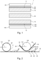
- Fig. 1 schematically shows a cross section of a card-like data carrier 1 which is manufactured by a method as described herein. The manufacturing method will be described in more detail with respect to Figures 2 and 3 . However, the general structure of the card-like data carrier 1 to be manufactured will be first described with respect to Fig. 1 .
- the card-like data carrier 1 basically comprises a core layer 10, a first adhesive layer 20 and a first intermediate layer 30.
- the core layer has a first surface 11 on which the first adhesive layer 20 is applied, wherein the first adhesive layer 20 is used to bond the first intermediate layer 30 to the core layer 10.
- the first intermediate layer 30 is also covered by a first top layer 40 which is arranged on top of the first intermediate layer 30.
- the first top layer 40 may be adhered to the first intermediate layer 30 or may laminated therewith during the manufacturing process. It is noted that gaps are illustrated in Fig. 1 between some of the layers, however, it should be understood that these gaps are merely shown for a better distinction between the different layers. Rather, after manufacturing, the layers may be in direct contact with each other.
- the core layer 10 includes an antenna element 50 which is configured for contactless communication with an external device, for example a card reading device.
- the antenna element 50 is integrated or embedded within the core layer 10 as shown in Fig. 1 .
- the card-like data carrier 1 may further comprise a chip element at an outer surface of the card-like data carrier 1, wherein the chip element is configured for a contact-based communication, e.g., data transfer, with an external device, for example a card reading device.
- the exemplary card-like data carrier 1 shown in Fig. 1 has a symmetrical appearance, wherein the core layer 10 including the antenna element 50 may provide the central structural part of the card-like data carrier 1.
- On each side of the core layer 10 may be an arrangement of an adhesive layer 20, 120, an intermediate layer 30, 130 and a top layer 40, 140, respectively.
- the card-like data carrier 1 may include a second adhesive layer 120 applied to a second surface 12 of the core layer 10, a second intermediate layer 130 and a second top layer 140.
- the second adhesive layer 120 is used to bond the second intermediate layer 130 to the second surface 12 of the core layer 10.
- the second intermediate layer 130 is covered by the second top layer 140 which is arranged on top of the second intermediate layer 130.
- the second top layer 140 may be adhered to the second intermediate layer 130 or may laminated therewith during the manufacturing process.
- the core layer 10 may be made of a plastic material, for example PVC.
- the intermediate layers 30, 130 may be metallic layers which provide a metallic effect to the card-like data carrier 1. It is exemplarily possible that the metallic effect may be also applied on a PET layer.
- One or both of the intermediate layers 30, 130 may thus comprise a metallic material or consist of a metallic material.
- the top layers 40, 140 may comprise a plastic material, for example PVC.
- Fig. 2 shows an application of an adhesive layer and an intermediate layer on a first surface of a core layer.
- Fig. 2 shows the application of the first adhesive layer 20 and the first intermediate layer 30 on the first surface 11 of the core layer 10, the layers being described above with respect to Fig. 1 .
- the first adhesive layer 20 is applied to a portion of the first surface 11 of the core layer 10. This means that the first adhesive layer 20 may be applied to multiple, spatially separated smaller parts of the first surface 11, but not to the entire first surface 11. However, if required by the customer, the first adhesive layer 20 may be applied to the entire first surface, in particular to the full ID-1 format area. In the example shown in Fig. 2 , three separate surface areas of the first surface 11 have been covered with the adhesive material of the first adhesive layer 20.
- a roller element 101 may be used to apply the adhesive layer 20 to the first surface of the core layer 10. During the application of the adhesive layer 20, the roller element 101 may be rolled over the first surface 11 of the core layer 10 in the rolling direction 110. Specified areas on an outer surface of the roller element may be provided with the adhesive such that, when rolling the roller element 101 over the first surface 11, the adhesive may be transferred to the corresponding surface areas at the first surface 11.
- the adhesive layer 20 may be applied only to surface areas on the first surface 11 where the intermediate layer 30 is desired to be present later on. In other words, it may not be desired to provide the metallic effect by the intermediate layer 30 for the entire card-like data carrier 1, but rather for specified areas of the card-like data carrier 1. Therefore, the method may include an application of the intermediate layer 30 comprising the metallic material only in those specified areas where the adhesive has been applied to the first surface 11. Accordingly, the adhesive layer 20 is applied to specified surface areas on the first surface 11 of the core layer 20 as shown for example in Fig. 2 .
- the intermediate layer 30 may be applied to the fist surface 11 of the core layer 10 which may include bonding the intermediate layer 30 to the first surface 11 via the adhesive layer 20.
- Another roller element 100 may be used to apply the intermediate layer to the first surface 11.
- the intermediate layer 30 may be carried by a carrier layer 33 or carrier film 33.
- the carrier film 33 may represent a support or carrier for the intermediate layer 30 during the application process of the intermediate layer 30.
- the intermediate layer 30 may be connected, e.g., bonded, to the carrier film 33.
- the combination of the intermediate layer 30 and the carrier film 33 may then be arranged between the roller element 100 and the cover layer 10.
- the intermediate layer 30 and the carrier film 33 is then pressed against the first surface 11 of the core layer 10 by rolling the roller element 100 over the first surface 11 in the rolling direction 110, thereby pressing the intermediate layer 30 against the specified portions of the adhesive layer 20 which are already present on the first surface 11.
- the carrier film 33 is drawn or pulled away from the first surface 11 such that parts of the intermediate layer 30 which were not bonded to the first surface 11 by the adhesive layer 20 are moved away from the first surface 11 together with the carrier film 33.
- the intermediate layer 30 is pressed against the first surface 11 of the core layer 10, thereby bonding a first part 31, e.g., including several subparts 31, of the intermediate layer 30 via the adhesive 20 to the first surface 11 of the core layer 10.
- a second part 32, e.g., including several subparts 32, of the intermediate layer 30 is moved away, e.g., removed, from the first surface 11 of the core layer 10, while the first part 31 of the intermediate layer 30 remains adhered to the first surface 11 of the core layer 10 such that the first surface 11 of the core layer 10 is covered by the first part 31 of the intermediate layer 30.
- three of such first parts 31 of the intermediate layer 30 were already bonded to the first surface 11.
- the removed second parts 32 of the intermediate layer 30 can be collected and reused after the first parts 31 of the intermediate layer 30 have been bonded to the first surface 11.
- the second parts 32 may be removed with the help of the carrier film 33 to which the second parts 32 of the intermediate layer 20 remain connected.
- the first parts 31 of the intermediate layer 30 were peeled-off the carrier film 33 due to the higher bonding forces between the first surface 11 and the first parts 31 of the intermediate layer 30 generated by the adhesive layer 20.
- the second parts 32 of the intermediate layer 20 were not peeled-off the carrier film 33 such that the second parts 32 of intermediate layer 20 can then be moved or transferred away from the manufacturing site to be reused or recycled in a further processing step. It is noted that the second parts 32 of the intermediate layer 20 may be easily separated from the carrier film 33 in such a further processing step.
- the combination of the carrier film material comprised in the carrier film 33 and the metallic material comprised in the second parts 32 of the intermediate layer 30 may be reused as a combined product.
- the metallic material can be reused although it may still comprise the material of the carrier film 33.
- the amount of carrier film material compared to the amount of metallic material is neglectable.
- the combined product of the metallic material and the carrier film material does not comprise any polyethylene terephthalate (PET).
- Fig. 3 shows a method for manufacturing a card-like data carrier 1, in particular a method for manufacturing the card-like data carrier 1 indicated with its cross-section in Fig. 1 , wherein reference is also made to Fig. 2 .
- a core layer 10 having a first surface 11 and a second surface 12 opposite to the first surface 11 is provided.
- an adhesive 20 is applied onto a portion of the first surface 11 of the core layer 10.
- an intermediate layer 30 comprising a metallic material is provided.
- the intermediate layer 30 may be arranged between at least one roller element 100 and the first surface 11 of the core layer 10.
- the intermediate layer 30 is pressed against the first surface 11 of the core layer 10, thereby bonding a first part 31 of the intermediate layer 30 via the adhesive 20 to the portion of the first surface 11 of the core layer 10.
- a second part 32 of the intermediate layer 30 is removed from the first surface 11 of the core layer 10, while the first part 31 of the intermediate layer 30 remains adhered to the portion of the first surface 11 of the core layer 10 such that the portion of the first surface 11 of the core layer 10 is covered by the first part 31 of the intermediate layer 30.
- a top layer 40 may be applied onto an uncovered portion of the first surface 11 of the core layer 10 and onto the first part 31 of the intermediate layer 30 after moving the second part 32 of the intermediate layer 30 away from the first surface 11 of the core layer 10.
- an ink material may be applied onto the first surface 11 of the core layer 10 before pressing the intermediate layer 30 against the first surface 11 of the core layer 10.
- the ink material may be applied to the first surface 11 before applying the adhesive 20 to the first surface 11.
- the second part 32 of the intermediate layer 30 may be reused after moving the second part 32 of the intermediate layer 30 away from the first surface 11 of the core layer 10.
- an adhesive 120 may be applied onto a portion of the second surface 12 of the core layer 10.
- a further intermediate layer 130 comprising a metallic material may be provided.
- the further intermediate layer 130 may be pressed against the second surface 12 of the core layer 10, thereby bonding a first part of the further intermediate layer 130 via the adhesive 20 to the portion of the second surface 12 of the core layer 10.
- a second part of the further intermediate layer 130 may be moved away from the second surface 12 of the core layer 10, while the first part of the further intermediate layer 130 remains adhered to the portion of the second surface 12 of the core layer 10.
- steps S18, S19, S20 and S21 may be performed simultaneously with steps S 11, S12, S13 and S 14.
- the method may include the simultaneous application of the adhesive layers 20, 120 and the metallic intermediate layers 30, 130, respectively, on both sides of the core layer 10.
Landscapes
- Health & Medical Sciences (AREA)
- Chemical & Material Sciences (AREA)
- Chemical Kinetics & Catalysis (AREA)
- General Chemical & Material Sciences (AREA)
- General Health & Medical Sciences (AREA)
- Toxicology (AREA)
- Engineering & Computer Science (AREA)
- Manufacturing & Machinery (AREA)
- Credit Cards Or The Like (AREA)
Abstract
Description
- The disclosure generally relates to the manufacturing of cards with metallic effect. In particular, the invention relates to a method for manufacturing a card-like data carrier and a use of such a method for manufacturing a chip-card, a payment card, a smart card or an identification card.
- Data carrier cards are used in various different applications. For example, bank cards like credit cards are used as payment cards which allow a user of the bank card to pay for purchased goods or services. Such data carrier cards are often manufactured in a standardized format and usually include different layers of plastic materials which are bonded to each other to provide a stack of layers. For example, the layers may be manufactured from polyvinylchloride (PVC), polyethylene terephthalate (PET), etc. Some data carrier cards also comprise a metallic material layer in order to provide a metallic effect to the card. However, the manufacturing of cards having such a metallic material layer often is inefficient due to the large amount of waste metallic material. In particular, during the manufacturing process of data carrier cards with metallic material layers, the metallic material is often combined with and thus mixed with plastic material. In most cases, some excess material will remain after the production process.
- However, due to the production process, the excess material includes a combination or mix of the metallic material and the plastic material which makes it difficult or impossible to separate the excess metallic material from the excess plastic material.
- It may be seen as an object of the invention to facilitate the recycling of excess material from a card manufacturing process.
- A method according to the features of the independent claim is provided. Further embodiments are evident from the dependent claims and from the following description.
- According to an aspect, a method for manufacturing a card-like data carrier is provided. In a step of the method, a core layer having a first surface and a second surface opposite to the first surface is provided. In a further step, an adhesive is applied onto a portion of the first surface of the core layer. In a further step, an intermediate layer comprising a metallic material is provided. In a further step, the intermediate layer is pressed against the first surface of the core layer, thereby bonding a first part of the intermediate layer via the adhesive to the portion of the first surface of the core layer. In a further step, a second part of the intermediate layer is moved away from the first surface of the core layer, while the first part of the intermediate layer remains adhered to the portion of the first surface of the core layer such that the portion of the first surface of the core layer is covered by the first part of the intermediate layer. Said method steps may be performed in the indicated order.
- The inventive method provides a manufacturing technique for card-like data carriers with metallic effect, in which excess material, in particular metallic material left-over from the manufacturing process, can be provided in such a way that it can be reused, e.g., recycled. This may be achieved by moving the potential excess material of the intermediate layer, i.e., the second part of the intermediate layer, away from the first surface of the core layer after the first part of the intermediate layer has been applied to the surface of the core layer. In particular, the intermediate layer allows the application of the metallic material to the core layer without using PET-based metallized foils and without using metallic inks.
- After manufacturing of the card-like data carrier, the removed second part of the intermediate layer may appear in a form or composition that can be directly reused or that can be easily separated from other material residuals. The inventive method thus facilitates the recycling of left-over materials from a card production process.
- The card-like data carrier that can be manufactured using the inventive method may comprise an ID-1 format, however, may also comprise other formats as well. The card-like data carrier can be chip-card, a payment card, a smart card or an identification card. In particular, the card-like data carrier can be a debit card or credit card.
- The card-like data carrier may comprise a chip element on an outer surface of the final card-like data carrier which is configured for a contact-communication, e.g., data transfer, with an external device, for example a card reading device. The card-like data carrier may comprise an antenna element which is configured for contactless communication with an external device, for example a card reading device. The antenna element may be integrated or embedded within the core layer.
- The core layer may be made of a plastic material and may constitute a structural base layer of the card-like data carrier to which other layers are applied, e.g., bonded. In particular, further layers of material may be bonded to the first surface of the core layer and also to the opposite second surface of the core layer. The result may be a stack of several material layers which together form the final card-like data carrier.
- The method comprises to apply the adhesive to the mentioned portion of the first surface of the core layer, which may include the provision of the adhesive only to one or more smaller parts of the first surface, but not to the entire first surface. However, if it is required by the customer, it is also possible that the adhesive is applied to the entire first surface. In particular, the adhesive may be applied only to a selected portion of the first surface where the metallic intermediate layer shall be present later. Other parts of the first surface of the core layer may remain without any adhesive. Therefore, the step of applying the adhesive to the first surface may be carried out such that the adhesive is only present in one or more surface areas or surface sections of the first surface, while other surface areas or surface sections of the first surface remain free of adhesive and are thus not covered with the adhesive. The adhesive may form an adhesive layer configured to bond further layers to the first surface of the core layer.
- The adhesive may be applied to the portion of the first surface using a roller element. The roller element may be configured to apply the adhesive to the selected portion of the first surface, for example by pressing the roller against the first surface.
- By the subsequent pressing of the metallic intermediate layer against the first surface of the core layer, the parts of the intermediate layer that respectively face the adhesive-covered surface areas or surface sections of the first surface of the core layer are bonded to the core layer via the adhesive. This means that not all parts of the intermediate layer may be bonded to the first surface of the core layer, but at least the parts of the intermediate layer which, due to the pressing, have a direct contact to the adhesive-covered areas or sections present at the first surface. Other parts of the intermediate layer which do not have a direct contact to the adhesive during the pressing will potentially not be bonded to the first surface of the core layer, thereby allowing these non-bonded parts to be moved away and thus be removed afterwards as will be further explained below.
- That is, the first part of the intermediate layer is bonded via the adhesive to the portion of the first surface of the core layer. Since the portion of the first surface where the adhesive was applied may include several surface areas or sections, the first part of the intermediate layer which is bonded via the adhesive may likewise include several subparts or subsections of the first part of the intermediate layer each of which is bonded to the first surface of the core layer via the adhesive. The surface areas or sections of the first surface of the core layer where the adhesive is applied may include spatially separated surface areas or sections. Accordingly, the subparts or subsections of the first part of the intermediate layer may constitute spatially separated subparts or subsections of the intermediate layer. In this manner, a pattern of metallic material may be provided by the application of the intermediate layer to the core layer, meaning that the metallic effect can be distributed within the card-like data carrier with various different patterns.
- As indicated above, the second part, i.e., all subparts or subsections of the intermediate layer which are not bonded to the first surface of the core layer, may be moved away, e.g., removed, after bonding the first part of the intermediate layer to the first surface of the core layer. The removal of the second part of the intermediate layer may be provided by a carrier layer, e.g., a carrier film, which is connected or bonded to the intermediate layer during provision of the intermediate layer and also during the pressing of the intermediate layer against the first surface of the core layer. After the pressing of the intermediate layer against the first surface of the core layer, the first part of the intermediate layer which is bonded to the portion of the first surface via the adhesive may be released or peeled-off the carrier layer such that only the second part of the intermediate layer which is not bonded to the first surface remains connected to the carrier layer. In this manner, it is possible that the second part of the metallic intermediate layer can be collected during the manufacturing process, thereby allowing a reuse or recycling of the second part of the metallic intermediate layer.
- According to an embodiment, the second part of the intermediate layer which is moved away from the first surface of the core layer is representative for a part of the intermediate layer which is not bonded via the adhesive to the portion of the first surface of the core layer.
- As explained above, this allows to collect the metallic material included in the left-over intermediate layer in order to reuse this metallic material. The removed second part of the intermediate layer may be supplied to a further treatment process in which the purity of the metallic material is further increased, for example by separating the material of the above-mentioned carrier layer from the metallic material of the intermediate layer.
- According to an embodiment, the core layer comprises a non-metallic material.
- The core layer may comprise a plastic material, for example polyvinylchloride (PVC). Thus, the core layer may herein also be referred to as the so-called PVC corestock. As indicated above, an antenna element or other circuitry may be embedded in the core layer.
- According to an embodiment, the intermediate layer comprises a carrier film having a surface on which the metallic material of the intermediate layer is present.
- As described above, the carrier film may be a carrier layer allowing the second part of the intermediate layer to be removed after the first part of the intermediate layer has been pressed against and bonded to the first surface of the core layer. The carrier layer may be in the form of a carrier film or carrier foil. This film or foil can be very thin, i.e., can have a very small thickness, and/or may have the function to carry and transport the intermediate layer to the first surface of the core layer and, after the bonding, move the second part of the intermediate layer away from the first surface of the core layer. In other words, the carrier layer may provide a transport function according to which the intermediate layer can be supplied to and parts of it can be moved away, e.g., removed, from the first surface of the core layer. The carrier layer may allow the bonded first part of the intermediate layer to be pulled-off, e.g., peeled-off, the carrier layer, while retaining the non-bonded second part of the intermediate layer such that the non-bonded second part of the intermediate layer can be moved away from the first surface of the core layer.
- It is possible that the carrier layer does not comprise any polyethylene terephthalate (PET) and/or ink materials. The method thus provides a way to produce card-like data carriers with metallic effect, without the use of PET-based metallic foils and without the use of metallic inks. In general, it is possible with the method to produce card-like data carriers without the bonding of two different plastic materials.
- According to an embodiment, the metallic material of the intermediate layer is present in the form of a metal foil which is supported on the surface of the carrier film.
- The intermediate layer may comprise or consist of the metal foil. This metal foil may be directly connected to the surface the carrier film such, for example also via an adhesive connection or the like.
- According to an embodiment, the method further comprises arranging the intermediate layer between at least one roller element and the first surface of the core layer.
- The at least one roller element may then press the intermediate layer against the first surface of the core layer to bond the first part of the intermediate layer via the adhesive to the portion of the first surface of the core layer. The roller element may be moved substantially parallel to the first surface while rolling over the first surface of the core layer, such that the first part of the intermediate layer is successively bonded to the corresponding portion of the first surface of the core layer.
- According to an embodiment, pressing the intermediate layer against the first surface of the core layer comprises pressing the intermediate layer against the first surface of the core layer using the at least one roller element.
- The roller element may be rolled over the first surface with the intermediate layer arranged there between while applying a specified pressure between the roller element and the first surface of the core layer. In this manner, the bonding between the first part of the intermediate layer and the portion of the first surface of the core layer can be ensured.
- According to an embodiment, the intermediate layer is successively pressed against the first surface of the core layer by successively rolling the at least one roller element over the first surface of the core layer.
- This may ensure that the entire first part of the intermediate layer is securely bonded to the portion of the first surface of the core layer.
- After the first part of the intermediate layer has been bonded to the portion of the first surface of the core layer, one or more further layers of material may be applied to cover the bonded first part of the intermediate layer and surface areas of the first surface of the core layer which are not covered by the first part of the intermediate layer. Such further layers may provide a so-called overlay for the card-like data carrier.
- According to an embodiment, the first part of the intermediate layer provides a metallic effect for the card-like data carrier.
- The metallic effect may be visible and recognizable from the outside of the card-like data carrier. In particular, the metallic effect may be perceived by a person viewing the card-like data carrier. The metallic effect may appear to the viewer as if there is a polished metal or metal pattern inside the card-like data carrier.
- According to an embodiment, the method further comprises applying a top layer onto an uncovered portion of the first surface of the core layer and onto the first part of the intermediate layer after moving the second part of the intermediate layer away from the first surface of the core layer.
- In particular, after the first part of the metallic intermediate layer has been bonded to the portion of the first surface of the core layer, there will be areas on the first surface at which the metallic intermediate layer is present, i.e., providing covered portions of the first surface of the core layer, as well as areas where the metallic intermediate layer was not bonded to the first surface, i.e., leaving uncovered portions of the first surface of the core layer. The top layer may now be applied over and bonded to these covered and uncovered portions of the first surface of the core layer, in order to provide an additional layer of the stack of layers which finally represent the card-like data carrier. The top layer may be a so-called overlay. The top layer may itself comprise multiple materials, for example multiple sheets of materials. The top layer may provide a protective function to the card-like data carrier and may thus protect the core layer, the antenna element, the intermediate layer and other elements of the card-like data carrier from mechanical or environmental influences.
- According to an embodiment, the top layer comprises a non-metallic material.
- For example, the top layer may comprise a PVC overlay and/or an additional overlay coating, wherein the PVC overlay may form the outermost layer of the manufactured card-like data carrier.
- According to an embodiment, the method further comprises providing an ink material onto the first surface of the core layer before pressing the intermediate layer against the first surface of the core layer.
- In other words, an ink layer may be provided to the first surface of the core layer in areas or sections of the first surface where no adhesive is or will be applied to the first surface. However, it is possible that the ink material may be provided as a continuous ink layer that covers the entire first surface. The ink material may be applied to the first surface of the core layer before the adhesive is applied to the portion of the first surface of the core layer.
- According to an embodiment, the method further comprises reusing the second part of the intermediate layer after moving the second part of the intermediate layer away from the first surface of the core layer.
- The method may thus be extended such that the manufacturing process may also encompass the recycling of the excess metallic material of the intermediate layer. This reusing may include a pre-treatment of the removed second part of the intermediate layer. For example, the metallic material of the intermediate layer is separated from the carrier layer mentioned above.
- According to an embodiment, the method comprises further steps. In a further step, an adhesive is applied onto a portion of the second surface of the core layer. In a further step, a further intermediate layer comprising a metallic material is provided. In a further step, the further intermediate layer is pressed against the second surface of the core layer, thereby bonding a first part of the further intermediate layer via the adhesive to the portion of the second surface of the core layer. In a further step, a second part of the further intermediate layer is moved away from the second surface of the core layer, while the first part of the further intermediate layer remains adhered to the portion of the second surface of the core layer such that the portion of the second surface of the core layer is covered by the first part of the further intermediate layer.
- In other words, the above-described manufacturing principles concerning the application of the first part of the intermediate layer via the adhesive to the portion of the first surface of the core layer may be extended to the opposite side of the core layer, i.e., to the second surface of the core layer. The above-described manufacturing principles concerning the application of one or more metallic parts to the first surface of the core layer, in terms of structure and functionality, may be equally valid for the application of one or more metallic parts to the second surface of the core layer.
- According to an aspect, the method as described herein is used for manufacturing a chip-card, a payment card, a smart card or an identification card.
- The present invention will hereinafter be described in conjunction with the following drawing figures, wherein like numerals denote like elements, and wherein:
- Fig. 1
- shows a cross section of a card-like data carrier manufactured by a method as described herein.
- Fig. 2
- shows an application of an adhesive layer and an intermediate layer on a first surface of a core layer.
- Fig. 3
- shows a method for manufacturing a card-like data carrier.
- The representations and illustrations in the drawings may be schematic and not to scale. A better understanding of the method described above may be obtained through a review of the shown illustrations together with a review of the detailed description that follows.
-
Fig. 1 schematically shows a cross section of a card-like data carrier 1 which is manufactured by a method as described herein. The manufacturing method will be described in more detail with respect toFigures 2 and3 . However, the general structure of the card-like data carrier 1 to be manufactured will be first described with respect toFig. 1 . - The card-
like data carrier 1 basically comprises acore layer 10, a firstadhesive layer 20 and a firstintermediate layer 30. The core layer has afirst surface 11 on which the firstadhesive layer 20 is applied, wherein the firstadhesive layer 20 is used to bond the firstintermediate layer 30 to thecore layer 10. - In the example shown in
Fig. 1 , the firstintermediate layer 30 is also covered by a firsttop layer 40 which is arranged on top of the firstintermediate layer 30. In particular, the firsttop layer 40 may be adhered to the firstintermediate layer 30 or may laminated therewith during the manufacturing process. It is noted that gaps are illustrated inFig. 1 between some of the layers, however, it should be understood that these gaps are merely shown for a better distinction between the different layers. Rather, after manufacturing, the layers may be in direct contact with each other. - The
core layer 10 includes anantenna element 50 which is configured for contactless communication with an external device, for example a card reading device. Theantenna element 50 is integrated or embedded within thecore layer 10 as shown inFig. 1 . Although not shown, the card-like data carrier 1 may further comprise a chip element at an outer surface of the card-like data carrier 1, wherein the chip element is configured for a contact-based communication, e.g., data transfer, with an external device, for example a card reading device. - The exemplary card-
like data carrier 1 shown inFig. 1 has a symmetrical appearance, wherein thecore layer 10 including theantenna element 50 may provide the central structural part of the card-like data carrier 1. On each side of thecore layer 10 may be an arrangement of anadhesive layer intermediate layer top layer - That is, in addition to the first
adhesive layer 20, the firstintermediate layer 30 and the firsttop layer 40, the card-like data carrier 1 may include a secondadhesive layer 120 applied to asecond surface 12 of thecore layer 10, a secondintermediate layer 130 and a secondtop layer 140. The secondadhesive layer 120 is used to bond the secondintermediate layer 130 to thesecond surface 12 of thecore layer 10. The secondintermediate layer 130 is covered by the secondtop layer 140 which is arranged on top of the secondintermediate layer 130. The secondtop layer 140 may be adhered to the secondintermediate layer 130 or may laminated therewith during the manufacturing process. - The
core layer 10 may be made of a plastic material, for example PVC. Theintermediate layers like data carrier 1. It is exemplarily possible that the metallic effect may be also applied on a PET layer. One or both of theintermediate layers -
Fig. 2 shows an application of an adhesive layer and an intermediate layer on a first surface of a core layer. In particular,Fig. 2 shows the application of the firstadhesive layer 20 and the firstintermediate layer 30 on thefirst surface 11 of thecore layer 10, the layers being described above with respect toFig. 1 . - The first
adhesive layer 20 is applied to a portion of thefirst surface 11 of thecore layer 10. This means that the firstadhesive layer 20 may be applied to multiple, spatially separated smaller parts of thefirst surface 11, but not to the entirefirst surface 11. However, if required by the customer, the firstadhesive layer 20 may be applied to the entire first surface, in particular to the full ID-1 format area. In the example shown inFig. 2 , three separate surface areas of thefirst surface 11 have been covered with the adhesive material of the firstadhesive layer 20. Aroller element 101 may be used to apply theadhesive layer 20 to the first surface of thecore layer 10. During the application of theadhesive layer 20, theroller element 101 may be rolled over thefirst surface 11 of thecore layer 10 in the rollingdirection 110. Specified areas on an outer surface of the roller element may be provided with the adhesive such that, when rolling theroller element 101 over thefirst surface 11, the adhesive may be transferred to the corresponding surface areas at thefirst surface 11. - It is noted that the
adhesive layer 20 may be applied only to surface areas on thefirst surface 11 where theintermediate layer 30 is desired to be present later on. In other words, it may not be desired to provide the metallic effect by theintermediate layer 30 for the entire card-like data carrier 1, but rather for specified areas of the card-like data carrier 1. Therefore, the method may include an application of theintermediate layer 30 comprising the metallic material only in those specified areas where the adhesive has been applied to thefirst surface 11. Accordingly, theadhesive layer 20 is applied to specified surface areas on thefirst surface 11 of thecore layer 20 as shown for example inFig. 2 . - After the application of the
adhesive layer 20, theintermediate layer 30 may be applied to thefist surface 11 of thecore layer 10 which may include bonding theintermediate layer 30 to thefirst surface 11 via theadhesive layer 20. Anotherroller element 100 may be used to apply the intermediate layer to thefirst surface 11. In particular, theintermediate layer 30 may be carried by acarrier layer 33 orcarrier film 33. Thecarrier film 33 may represent a support or carrier for theintermediate layer 30 during the application process of theintermediate layer 30. For example, theintermediate layer 30 may be connected, e.g., bonded, to thecarrier film 33. The combination of theintermediate layer 30 and thecarrier film 33 may then be arranged between theroller element 100 and thecover layer 10. Theintermediate layer 30 and thecarrier film 33 is then pressed against thefirst surface 11 of thecore layer 10 by rolling theroller element 100 over thefirst surface 11 in the rollingdirection 110, thereby pressing theintermediate layer 30 against the specified portions of theadhesive layer 20 which are already present on thefirst surface 11. After theroller element 100 has been rolled over these specified portions, thecarrier film 33 is drawn or pulled away from thefirst surface 11 such that parts of theintermediate layer 30 which were not bonded to thefirst surface 11 by theadhesive layer 20 are moved away from thefirst surface 11 together with thecarrier film 33. - In other words, the
intermediate layer 30 is pressed against thefirst surface 11 of thecore layer 10, thereby bonding a first part 31, e.g., including several subparts 31, of theintermediate layer 30 via the adhesive 20 to thefirst surface 11 of thecore layer 10. A second part 32, e.g., including several subparts 32, of theintermediate layer 30 is moved away, e.g., removed, from thefirst surface 11 of thecore layer 10, while the first part 31 of theintermediate layer 30 remains adhered to thefirst surface 11 of thecore layer 10 such that thefirst surface 11 of thecore layer 10 is covered by the first part 31 of theintermediate layer 30. In the example shown inFig. 2 , three of such first parts 31 of theintermediate layer 30 were already bonded to thefirst surface 11. - In this manner, the removed second parts 32 of the
intermediate layer 30 can be collected and reused after the first parts 31 of theintermediate layer 30 have been bonded to thefirst surface 11. The second parts 32 may be removed with the help of thecarrier film 33 to which the second parts 32 of theintermediate layer 20 remain connected. - In particular, the first parts 31 of the
intermediate layer 30 were peeled-off thecarrier film 33 due to the higher bonding forces between thefirst surface 11 and the first parts 31 of theintermediate layer 30 generated by theadhesive layer 20. The second parts 32 of theintermediate layer 20 were not peeled-off thecarrier film 33 such that the second parts 32 ofintermediate layer 20 can then be moved or transferred away from the manufacturing site to be reused or recycled in a further processing step. It is noted that the second parts 32 of theintermediate layer 20 may be easily separated from thecarrier film 33 in such a further processing step. However, it may also be possible that the combination of the carrier film material comprised in thecarrier film 33 and the metallic material comprised in the second parts 32 of theintermediate layer 30 may be reused as a combined product. For example, the metallic material can be reused although it may still comprise the material of thecarrier film 33. For example, the amount of carrier film material compared to the amount of metallic material is neglectable. Preferably, the combined product of the metallic material and the carrier film material does not comprise any polyethylene terephthalate (PET). -
Fig. 3 shows a method for manufacturing a card-like data carrier 1, in particular a method for manufacturing the card-like data carrier 1 indicated with its cross-section inFig. 1 , wherein reference is also made toFig. 2 . In a step S10 of the method, acore layer 10 having afirst surface 11 and asecond surface 12 opposite to thefirst surface 11 is provided. In a further step S11, an adhesive 20 is applied onto a portion of thefirst surface 11 of thecore layer 10. In a further step S12, anintermediate layer 30 comprising a metallic material is provided. In a further step S12a, theintermediate layer 30 may be arranged between at least oneroller element 100 and thefirst surface 11 of thecore layer 10. In a further step S13, theintermediate layer 30 is pressed against thefirst surface 11 of thecore layer 10, thereby bonding a first part 31 of theintermediate layer 30 via the adhesive 20 to the portion of thefirst surface 11 of thecore layer 10. In a further step S14, a second part 32 of theintermediate layer 30 is removed from thefirst surface 11 of thecore layer 10, while the first part 31 of theintermediate layer 30 remains adhered to the portion of thefirst surface 11 of thecore layer 10 such that the portion of thefirst surface 11 of thecore layer 10 is covered by the first part 31 of theintermediate layer 30. - In a further step S 15, a
top layer 40 may be applied onto an uncovered portion of thefirst surface 11 of thecore layer 10 and onto the first part 31 of theintermediate layer 30 after moving the second part 32 of theintermediate layer 30 away from thefirst surface 11 of thecore layer 10. In a further step S16, an ink material may be applied onto thefirst surface 11 of thecore layer 10 before pressing theintermediate layer 30 against thefirst surface 11 of thecore layer 10. Alternatively, the ink material may be applied to thefirst surface 11 before applying the adhesive 20 to thefirst surface 11. In a further step S17, the second part 32 of theintermediate layer 30 may be reused after moving the second part 32 of theintermediate layer 30 away from thefirst surface 11 of thecore layer 10. - In a further step S18, an adhesive 120 may be applied onto a portion of the
second surface 12 of thecore layer 10. In a further step S19, a furtherintermediate layer 130 comprising a metallic material may be provided. In a further step S20, the furtherintermediate layer 130 may be pressed against thesecond surface 12 of thecore layer 10, thereby bonding a first part of the furtherintermediate layer 130 via the adhesive 20 to the portion of thesecond surface 12 of thecore layer 10. In a further step S21, a second part of the furtherintermediate layer 130 may be moved away from thesecond surface 12 of thecore layer 10, while the first part of the furtherintermediate layer 130 remains adhered to the portion of thesecond surface 12 of thecore layer 10. - It is possible that the steps S18, S19, S20 and S21 may be performed simultaneously with steps S 11, S12, S13 and S 14. In other words, the method may include the simultaneous application of the
adhesive layers intermediate layers core layer 10.
Claims (15)
- A method for manufacturing a card-like data carrier (1), comprising:providing a core layer (10) having a first surface (11) and a second surface (12) opposite to the first surface (11, S10);applying an adhesive (20) onto a portion of the first surface (11) of the core layer (10, S11);providing an intermediate layer (30) comprising a metallic material (S12);pressing the intermediate layer (30) against the first surface (11) of the core layer (10), thereby bonding a first part (31) of the intermediate layer (30) via the adhesive (20) to the portion of the first surface (11) of the core layer (10, S13);moving a second part (32) of the intermediate layer (30) away from the first surface (11) of the core layer (10), while the first part (31) of the intermediate layer (30) remains adhered to the portion of the first surface (11) of the core layer (10) such that the portion of the first surface (11) of the core layer (10) is covered by the first part (31) of the intermediate layer (30, S14).
- The method of claim 1,
wherein the second part (32) of the intermediate layer (30) is representative for a part of the intermediate layer (30) which is not bonded via the adhesive (20) to the portion of the first surface (11) of the core layer (10). - The method according to any one of the preceding claims,
wherein the core layer (10) comprises a non-metallic material. - The method according to any one of the preceding claims,
wherein the intermediate layer (30) comprises a carrier film (33) having a surface (34) on which the metallic material of the intermediate layer (30) is present. - The method according to claim 4,
wherein the metallic material is present in the form of a metal foil which is supported on the surface (34) of the carrier film (33). - The method according to any one of the preceding claims, further comprising:
arranging the intermediate layer (30) between at least one roller element (100) and the first surface (11) of the core layer (10, S12a). - The method according to claim 6,
wherein pressing the intermediate layer (30) against the first surface (11) of the core layer (10) comprises pressing the intermediate layer (30) against the first surface (11) of the core layer (30) using the at least one roller element (100). - The method according to any one of claims 6 to 7,
wherein intermediate layer (30) is successively pressed against the first surface (11) of the core layer (10) by successively rolling the at least one roller element (100) over the first surface (11) of the core layer (10). - The method according to any one of the preceding claims,
wherein the first part (31) of the intermediate layer (30) provides a metallic effect for the card-like data carrier (1). - The method according to any one of the preceding claims, further comprising:
applying top layer (40) onto an uncovered portion of the first surface (11) of the core layer (10) and onto the first part (31) of the intermediate layer (30) after moving the second part (32) of the intermediate layer (30) away from the first surface (11) of the core layer (10, S15). - The method according to claim 10,
wherein the top layer (40) comprises a non-metallic material. - The method according to any one of the preceding claims, further comprising:
applying an ink material onto the first surface (11) of the core layer (10) before pressing the intermediate layer (30) against the first surface (11) of the core layer (10, S16). - The method according to any one of the preceding claims, further comprising:
reusing the second part (32) of the intermediate layer (30) after moving the second part (32) of the intermediate layer (30) away from the first surface (11) of the core layer (10, S17). - The method according to any one of the preceding claims,applying an adhesive (20) onto a portion of the second surface (12) of the core layer (10, S18);providing a further intermediate layer (130) comprising a metallic material (S19);pressing the further intermediate layer (130) against the second surface (12) of the core layer (10), thereby bonding a first part of the further intermediate layer (130) via the adhesive (20) to the portion of the second surface (12) of the core layer (10, S20);moving a second part of the further intermediate layer (130) away from the second surface (12) of the core layer (10), while the first part of the further intermediate layer (130) remains adhered to the portion of the second surface (12) of the core layer (10, S21).
- Use of a method according to any one of the preceding claims for manufacturing a chip-card, a payment card, a smart card or an identification card.
Priority Applications (2)
| Application Number | Priority Date | Filing Date | Title |
|---|---|---|---|
| EP23382881.3A EP4516504B1 (en) | 2023-08-29 | 2023-08-29 | Method for manufacturing a card-like data carrier |
| ES23382881T ES3052666T3 (en) | 2023-08-29 | 2023-08-29 | Method for manufacturing a card-like data carrier |
Applications Claiming Priority (1)
| Application Number | Priority Date | Filing Date | Title |
|---|---|---|---|
| EP23382881.3A EP4516504B1 (en) | 2023-08-29 | 2023-08-29 | Method for manufacturing a card-like data carrier |
Publications (2)
| Publication Number | Publication Date |
|---|---|
| EP4516504A1 true EP4516504A1 (en) | 2025-03-05 |
| EP4516504B1 EP4516504B1 (en) | 2025-10-01 |
Family
ID=87863659
Family Applications (1)
| Application Number | Title | Priority Date | Filing Date |
|---|---|---|---|
| EP23382881.3A Active EP4516504B1 (en) | 2023-08-29 | 2023-08-29 | Method for manufacturing a card-like data carrier |
Country Status (2)
| Country | Link |
|---|---|
| EP (1) | EP4516504B1 (en) |
| ES (1) | ES3052666T3 (en) |
Citations (3)
| Publication number | Priority date | Publication date | Assignee | Title |
|---|---|---|---|---|
| DE102012223700A1 (en) * | 2012-12-19 | 2014-06-26 | Bundesdruckerei Gmbh | Method for producing a security feature for a value and / or security product and value and / or security product (pixelated application element) |
| US20180215190A1 (en) * | 2015-08-05 | 2018-08-02 | Leonhard Kurz Stiftung & Co. Kg | Method and Device for Producing a Multilayer Film |
| WO2019224159A1 (en) * | 2018-05-25 | 2019-11-28 | Ovd Kinegram Ag | Method for producing a laminated body and a laminating film and laminated body and laminating film |
-
2023
- 2023-08-29 ES ES23382881T patent/ES3052666T3/en active Active
- 2023-08-29 EP EP23382881.3A patent/EP4516504B1/en active Active
Patent Citations (3)
| Publication number | Priority date | Publication date | Assignee | Title |
|---|---|---|---|---|
| DE102012223700A1 (en) * | 2012-12-19 | 2014-06-26 | Bundesdruckerei Gmbh | Method for producing a security feature for a value and / or security product and value and / or security product (pixelated application element) |
| US20180215190A1 (en) * | 2015-08-05 | 2018-08-02 | Leonhard Kurz Stiftung & Co. Kg | Method and Device for Producing a Multilayer Film |
| WO2019224159A1 (en) * | 2018-05-25 | 2019-11-28 | Ovd Kinegram Ag | Method for producing a laminated body and a laminating film and laminated body and laminating film |
Also Published As
| Publication number | Publication date |
|---|---|
| EP4516504B1 (en) | 2025-10-01 |
| ES3052666T3 (en) | 2026-01-12 |
Similar Documents
| Publication | Publication Date | Title |
|---|---|---|
| US6644551B2 (en) | Card | |
| CA2608458C (en) | Multi-layer cards with aesthetic features and related methods of manufacturing | |
| US6557766B1 (en) | Hot lamination method for a hybrid radio frequency optical memory card converting sheets into a web process | |
| USRE40145E1 (en) | Ultra-thin flexible durable radio frequency identification devices and hot or cold lamination process for the manufacture of ultra-thin flexible durable radio frequency identification devices | |
| AU2023206103B2 (en) | Recovered plastic cards | |
| US12254370B2 (en) | Recovered plastic cards | |
| EP0249266A1 (en) | Data-carrying card, method for producing such a card, and device for carrying out said method | |
| EP1029305B1 (en) | Method and apparatus for the automatic production of personalized cards and pouches | |
| US20190385035A1 (en) | Edge-to-edge metal card and production method | |
| EP4516504B1 (en) | Method for manufacturing a card-like data carrier | |
| US10970612B2 (en) | Interactive core for electronic cards | |
| EP1388808B1 (en) | Data carrier | |
| NL8801246A (en) | LAMINATED ID CARD AND A METHOD FOR MANUFACTURING IT. | |
| CN2715254Y (en) | Special-shaped non-contact IC transaction card | |
| CN119337909A (en) | Preparation method of card body with information interaction function and card body with information interaction function |
Legal Events
| Date | Code | Title | Description |
|---|---|---|---|
| PUAI | Public reference made under article 153(3) epc to a published international application that has entered the european phase |
Free format text: ORIGINAL CODE: 0009012 |
|
| STAA | Information on the status of an ep patent application or granted ep patent |
Free format text: STATUS: THE APPLICATION HAS BEEN PUBLISHED |
|
| AK | Designated contracting states |
Kind code of ref document: A1 Designated state(s): AL AT BE BG CH CY CZ DE DK EE ES FI FR GB GR HR HU IE IS IT LI LT LU LV MC ME MK MT NL NO PL PT RO RS SE SI SK SM TR |
|
| STAA | Information on the status of an ep patent application or granted ep patent |
Free format text: STATUS: REQUEST FOR EXAMINATION WAS MADE |
|
| 17P | Request for examination filed |
Effective date: 20250417 |
|
| GRAP | Despatch of communication of intention to grant a patent |
Free format text: ORIGINAL CODE: EPIDOSNIGR1 |
|
| STAA | Information on the status of an ep patent application or granted ep patent |
Free format text: STATUS: GRANT OF PATENT IS INTENDED |
|
| INTG | Intention to grant announced |
Effective date: 20250602 |
|
| GRAS | Grant fee paid |
Free format text: ORIGINAL CODE: EPIDOSNIGR3 |
|
| GRAA | (expected) grant |
Free format text: ORIGINAL CODE: 0009210 |
|
| STAA | Information on the status of an ep patent application or granted ep patent |
Free format text: STATUS: THE PATENT HAS BEEN GRANTED |
|
| AK | Designated contracting states |
Kind code of ref document: B1 Designated state(s): AL AT BE BG CH CY CZ DE DK EE ES FI FR GB GR HR HU IE IS IT LI LT LU LV MC ME MK MT NL NO PL PT RO RS SE SI SK SM TR |
|
| REG | Reference to a national code |
Ref country code: GB Ref legal event code: FG4D Ref country code: CH Ref legal event code: F10 Free format text: ST27 STATUS EVENT CODE: U-0-0-F10-F00 (AS PROVIDED BY THE NATIONAL OFFICE) Effective date: 20251001 |
|
| REG | Reference to a national code |
Ref country code: IE Ref legal event code: FG4D |
|
| REG | Reference to a national code |
Ref country code: DE Ref legal event code: R096 Ref document number: 602023007161 Country of ref document: DE |
|
| P01 | Opt-out of the competence of the unified patent court (upc) registered |
Free format text: CASE NUMBER: UPC_APP_7864_4516504/2025 Effective date: 20250924 |
|
| REG | Reference to a national code |
Ref country code: ES Ref legal event code: FG2A Ref document number: 3052666 Country of ref document: ES Kind code of ref document: T3 Effective date: 20260112 |
|
| REG | Reference to a national code |
Ref country code: NL Ref legal event code: MP Effective date: 20251001 |
|
| REG | Reference to a national code |
Ref country code: AT Ref legal event code: MK05 Ref document number: 1842137 Country of ref document: AT Kind code of ref document: T Effective date: 20251001 |
|
| PG25 | Lapsed in a contracting state [announced via postgrant information from national office to epo] |
Ref country code: NL Free format text: LAPSE BECAUSE OF FAILURE TO SUBMIT A TRANSLATION OF THE DESCRIPTION OR TO PAY THE FEE WITHIN THE PRESCRIBED TIME-LIMIT Effective date: 20251001 |
|
| REG | Reference to a national code |
Ref country code: LT Ref legal event code: MG9D |
|
| PG25 | Lapsed in a contracting state [announced via postgrant information from national office to epo] |
Ref country code: NO Free format text: LAPSE BECAUSE OF FAILURE TO SUBMIT A TRANSLATION OF THE DESCRIPTION OR TO PAY THE FEE WITHIN THE PRESCRIBED TIME-LIMIT Effective date: 20260101 |
|
| PG25 | Lapsed in a contracting state [announced via postgrant information from national office to epo] |
Ref country code: FI Free format text: LAPSE BECAUSE OF FAILURE TO SUBMIT A TRANSLATION OF THE DESCRIPTION OR TO PAY THE FEE WITHIN THE PRESCRIBED TIME-LIMIT Effective date: 20251001 Ref country code: HR Free format text: LAPSE BECAUSE OF FAILURE TO SUBMIT A TRANSLATION OF THE DESCRIPTION OR TO PAY THE FEE WITHIN THE PRESCRIBED TIME-LIMIT Effective date: 20251001 Ref country code: AT Free format text: LAPSE BECAUSE OF FAILURE TO SUBMIT A TRANSLATION OF THE DESCRIPTION OR TO PAY THE FEE WITHIN THE PRESCRIBED TIME-LIMIT Effective date: 20251001 |
|
| PG25 | Lapsed in a contracting state [announced via postgrant information from national office to epo] |
Ref country code: RS Free format text: LAPSE BECAUSE OF FAILURE TO SUBMIT A TRANSLATION OF THE DESCRIPTION OR TO PAY THE FEE WITHIN THE PRESCRIBED TIME-LIMIT Effective date: 20260101 |
|
| PG25 | Lapsed in a contracting state [announced via postgrant information from national office to epo] |
Ref country code: IS Free format text: LAPSE BECAUSE OF FAILURE TO SUBMIT A TRANSLATION OF THE DESCRIPTION OR TO PAY THE FEE WITHIN THE PRESCRIBED TIME-LIMIT Effective date: 20260201 |
|
| PG25 | Lapsed in a contracting state [announced via postgrant information from national office to epo] |
Ref country code: PT Free format text: LAPSE BECAUSE OF FAILURE TO SUBMIT A TRANSLATION OF THE DESCRIPTION OR TO PAY THE FEE WITHIN THE PRESCRIBED TIME-LIMIT Effective date: 20260202 Ref country code: CZ Free format text: LAPSE BECAUSE OF FAILURE TO SUBMIT A TRANSLATION OF THE DESCRIPTION OR TO PAY THE FEE WITHIN THE PRESCRIBED TIME-LIMIT Effective date: 20251001 |
|
| PG25 | Lapsed in a contracting state [announced via postgrant information from national office to epo] |
Ref country code: PL Free format text: LAPSE BECAUSE OF FAILURE TO SUBMIT A TRANSLATION OF THE DESCRIPTION OR TO PAY THE FEE WITHIN THE PRESCRIBED TIME-LIMIT Effective date: 20251001 |
|
| PG25 | Lapsed in a contracting state [announced via postgrant information from national office to epo] |
Ref country code: LV Free format text: LAPSE BECAUSE OF FAILURE TO SUBMIT A TRANSLATION OF THE DESCRIPTION OR TO PAY THE FEE WITHIN THE PRESCRIBED TIME-LIMIT Effective date: 20251001 |
|
| PG25 | Lapsed in a contracting state [announced via postgrant information from national office to epo] |
Ref country code: BG Free format text: LAPSE BECAUSE OF FAILURE TO SUBMIT A TRANSLATION OF THE DESCRIPTION OR TO PAY THE FEE WITHIN THE PRESCRIBED TIME-LIMIT Effective date: 20251001 |