EP4516494A1 - Method for manufacturing a wind turbine blade or wind turbine blade section and grinding apparatus - Google Patents
Method for manufacturing a wind turbine blade or wind turbine blade section and grinding apparatus Download PDFInfo
- Publication number
- EP4516494A1 EP4516494A1 EP23194289.7A EP23194289A EP4516494A1 EP 4516494 A1 EP4516494 A1 EP 4516494A1 EP 23194289 A EP23194289 A EP 23194289A EP 4516494 A1 EP4516494 A1 EP 4516494A1
- Authority
- EP
- European Patent Office
- Prior art keywords
- wind turbine
- turbine blade
- tool head
- grinding
- raw wind
- Prior art date
- Legal status (The legal status is an assumption and is not a legal conclusion. Google has not performed a legal analysis and makes no representation as to the accuracy of the status listed.)
- Withdrawn
Links
Images


Classifications
-
- B—PERFORMING OPERATIONS; TRANSPORTING
- B29—WORKING OF PLASTICS; WORKING OF SUBSTANCES IN A PLASTIC STATE IN GENERAL
- B29C—SHAPING OR JOINING OF PLASTICS; SHAPING OF MATERIAL IN A PLASTIC STATE, NOT OTHERWISE PROVIDED FOR; AFTER-TREATMENT OF THE SHAPED PRODUCTS, e.g. REPAIRING
- B29C70/00—Shaping composites, i.e. plastics material comprising reinforcements, fillers or preformed parts, e.g. inserts
- B29C70/04—Shaping composites, i.e. plastics material comprising reinforcements, fillers or preformed parts, e.g. inserts comprising reinforcements only, e.g. self-reinforcing plastics
- B29C70/28—Shaping operations therefor
- B29C70/54—Component parts, details or accessories; Auxiliary operations, e.g. feeding or storage of prepregs or SMC after impregnation or during ageing
- B29C70/545—Perforating, cutting or machining during or after moulding
-
- B—PERFORMING OPERATIONS; TRANSPORTING
- B24—GRINDING; POLISHING
- B24B—MACHINES, DEVICES, OR PROCESSES FOR GRINDING OR POLISHING; DRESSING OR CONDITIONING OF ABRADING SURFACES; FEEDING OF GRINDING, POLISHING, OR LAPPING AGENTS
- B24B19/00—Single-purpose machines or devices for particular grinding operations not covered by any other main group
- B24B19/14—Single-purpose machines or devices for particular grinding operations not covered by any other main group for grinding turbine blades, propeller blades or the like
-
- B—PERFORMING OPERATIONS; TRANSPORTING
- B24—GRINDING; POLISHING
- B24B—MACHINES, DEVICES, OR PROCESSES FOR GRINDING OR POLISHING; DRESSING OR CONDITIONING OF ABRADING SURFACES; FEEDING OF GRINDING, POLISHING, OR LAPPING AGENTS
- B24B29/00—Machines or devices for polishing surfaces on work by means of tools made of soft or flexible material with or without the application of solid or liquid polishing agents
- B24B29/02—Machines or devices for polishing surfaces on work by means of tools made of soft or flexible material with or without the application of solid or liquid polishing agents designed for particular workpieces
-
- B—PERFORMING OPERATIONS; TRANSPORTING
- B24—GRINDING; POLISHING
- B24B—MACHINES, DEVICES, OR PROCESSES FOR GRINDING OR POLISHING; DRESSING OR CONDITIONING OF ABRADING SURFACES; FEEDING OF GRINDING, POLISHING, OR LAPPING AGENTS
- B24B5/00—Machines or devices designed for grinding surfaces of revolution on work, including those which also grind adjacent plane surfaces; Accessories therefor
- B24B5/36—Single-purpose machines or devices
- B24B5/363—Single-purpose machines or devices for grinding surfaces of revolution in situ
-
- B—PERFORMING OPERATIONS; TRANSPORTING
- B24—GRINDING; POLISHING
- B24B—MACHINES, DEVICES, OR PROCESSES FOR GRINDING OR POLISHING; DRESSING OR CONDITIONING OF ABRADING SURFACES; FEEDING OF GRINDING, POLISHING, OR LAPPING AGENTS
- B24B55/00—Safety devices for grinding or polishing machines; Accessories fitted to grinding or polishing machines for keeping tools or parts of the machine in good working condition
- B24B55/06—Dust extraction equipment on grinding or polishing machines
-
- B—PERFORMING OPERATIONS; TRANSPORTING
- B24—GRINDING; POLISHING
- B24D—TOOLS FOR GRINDING, BUFFING OR SHARPENING
- B24D13/00—Wheels having flexibly-acting working parts, e.g. buffing wheels; Mountings therefor
- B24D13/14—Wheels having flexibly-acting working parts, e.g. buffing wheels; Mountings therefor acting by the front face
- B24D13/142—Wheels of special form
-
- B—PERFORMING OPERATIONS; TRANSPORTING
- B29—WORKING OF PLASTICS; WORKING OF SUBSTANCES IN A PLASTIC STATE IN GENERAL
- B29C—SHAPING OR JOINING OF PLASTICS; SHAPING OF MATERIAL IN A PLASTIC STATE, NOT OTHERWISE PROVIDED FOR; AFTER-TREATMENT OF THE SHAPED PRODUCTS, e.g. REPAIRING
- B29C73/00—Repairing of articles made from plastics or substances in a plastic state, e.g. of articles shaped or produced by using techniques covered by this subclass or subclass B29D
- B29C73/02—Repairing of articles made from plastics or substances in a plastic state, e.g. of articles shaped or produced by using techniques covered by this subclass or subclass B29D using liquid or paste-like material
-
- B—PERFORMING OPERATIONS; TRANSPORTING
- B29—WORKING OF PLASTICS; WORKING OF SUBSTANCES IN A PLASTIC STATE IN GENERAL
- B29D—PRODUCING PARTICULAR ARTICLES FROM PLASTICS OR FROM SUBSTANCES IN A PLASTIC STATE
- B29D99/00—Subject matter not provided for in other groups of this subclass
- B29D99/0025—Producing blades or the like, e.g. blades for turbines, propellers, or wings
-
- B—PERFORMING OPERATIONS; TRANSPORTING
- B33—ADDITIVE MANUFACTURING TECHNOLOGY
- B33Y—ADDITIVE MANUFACTURING, i.e. MANUFACTURING OF THREE-DIMENSIONAL [3D] OBJECTS BY ADDITIVE DEPOSITION, ADDITIVE AGGLOMERATION OR ADDITIVE LAYERING, e.g. BY 3D PRINTING, STEREOLITHOGRAPHY OR SELECTIVE LASER SINTERING
- B33Y10/00—Processes of additive manufacturing
-
- B—PERFORMING OPERATIONS; TRANSPORTING
- B33—ADDITIVE MANUFACTURING TECHNOLOGY
- B33Y—ADDITIVE MANUFACTURING, i.e. MANUFACTURING OF THREE-DIMENSIONAL [3D] OBJECTS BY ADDITIVE DEPOSITION, ADDITIVE AGGLOMERATION OR ADDITIVE LAYERING, e.g. BY 3D PRINTING, STEREOLITHOGRAPHY OR SELECTIVE LASER SINTERING
- B33Y80/00—Products made by additive manufacturing
-
- F—MECHANICAL ENGINEERING; LIGHTING; HEATING; WEAPONS; BLASTING
- F03—MACHINES OR ENGINES FOR LIQUIDS; WIND, SPRING, OR WEIGHT MOTORS; PRODUCING MECHANICAL POWER OR A REACTIVE PROPULSIVE THRUST, NOT OTHERWISE PROVIDED FOR
- F03D—WIND MOTORS
- F03D1/00—Wind motors with rotation axis substantially parallel to the air flow entering the rotor
- F03D1/06—Rotors
- F03D1/065—Rotors characterised by their construction elements
- F03D1/0675—Rotors characterised by their construction elements of the blades
-
- B—PERFORMING OPERATIONS; TRANSPORTING
- B05—SPRAYING OR ATOMISING IN GENERAL; APPLYING FLUENT MATERIALS TO SURFACES, IN GENERAL
- B05D—PROCESSES FOR APPLYING FLUENT MATERIALS TO SURFACES, IN GENERAL
- B05D1/00—Processes for applying liquids or other fluent materials
- B05D1/40—Distributing applied liquids or other fluent materials by members moving relatively to surface
- B05D1/42—Distributing applied liquids or other fluent materials by members moving relatively to surface by non-rotary members
-
- B—PERFORMING OPERATIONS; TRANSPORTING
- B29—WORKING OF PLASTICS; WORKING OF SUBSTANCES IN A PLASTIC STATE IN GENERAL
- B29L—INDEXING SCHEME ASSOCIATED WITH SUBCLASS B29C, RELATING TO PARTICULAR ARTICLES
- B29L2031/00—Other particular articles
- B29L2031/08—Blades for rotors, stators, fans, turbines or the like, e.g. screw propellers
- B29L2031/082—Blades, e.g. for helicopters
- B29L2031/085—Wind turbine blades
-
- Y—GENERAL TAGGING OF NEW TECHNOLOGICAL DEVELOPMENTS; GENERAL TAGGING OF CROSS-SECTIONAL TECHNOLOGIES SPANNING OVER SEVERAL SECTIONS OF THE IPC; TECHNICAL SUBJECTS COVERED BY FORMER USPC CROSS-REFERENCE ART COLLECTIONS [XRACs] AND DIGESTS
- Y02—TECHNOLOGIES OR APPLICATIONS FOR MITIGATION OR ADAPTATION AGAINST CLIMATE CHANGE
- Y02P—CLIMATE CHANGE MITIGATION TECHNOLOGIES IN THE PRODUCTION OR PROCESSING OF GOODS
- Y02P70/00—Climate change mitigation technologies in the production process for final industrial or consumer products
- Y02P70/50—Manufacturing or production processes characterised by the final manufactured product
Definitions
- the present invention relates to a method for manufacturing a wind turbine blade or wind turbine blade section and to a grinding apparatus for grinding a grinding area of a raw wind turbine blade or raw wind turbine blade section, the grinding area having an extension along a spanwise direction of the raw wind turbine blade or raw wind turbine blade section and a convex or concave curved cross-section.
- Wind turbine blades especially for offshore use, with the evolvement of technology continuously increase in size.
- current blades can reach a root diameter of approximately 4m, a blade length of well over 100m while typical chord lengths can reach up to 7m or even more.
- a major portion of the manual labor is represented by grinding work at the outer surface of the blade.
- wind turbine blades are manufactured by lamination of multiple layers of fiber material in a mold having the shape of a negative impression of the outer blade geometry.
- a typical fiber material layup in a mold includes one or multiple air extraction means that are adapted to extract excess air from the mold before and/or during resin infusion of the fiber material layup.
- the air extraction means do not become part of the final blade structure but are an auxiliary production tool.
- Typical air extraction means include semipermeable membranes, i.e. membranes that allow gases, in particular air, to pass and block the passage of liquids, in particular resin.
- the permeable membranes are connected to a vacuum source located externally of the mold so that excess air from the mold can be extracted therefrom.
- filters are also referred to as "filters”.
- the air extraction means are typically placed in the mold with an extension along a spanwise or longitudinal direction so that the raw wind turbine blade after removing it from the mold has grooves at its outer surface running along the spanwise or longitudinal direction at the positions where the air extraction means have been placed in the mold.
- grooves have to be filled with a hardenable filler material to restore the intended airfoil geometry of the final wind turbine blade.
- excess filler material e.g. residual filler material protruding beyond the intended airfoil geometry and/or laterally outwardly from the groove, has to be ground off. This is currently done by manual labor which, depending on the concrete dimensions of the blade, may take over 60 man-hours which is unproductive and expensive.
- the method comprises the following steps:
- the raw wind turbine blade or raw wind turbine blade section might also be referred to as “green wind turbine blade” or “green wind turbine blade section”.
- the at least one groove might in particular have a depth between 1 mm and 10 mm, in particular between 2 mm and 5 mm.
- the at least one groove might be the result of previous process steps, in particular it might represent a negative impression of a volume in that air extraction means or "filters" have been placed in a mold for lamination of the raw wind turbine blade or raw wind turbine blade section.
- the adaption of the shape of the tool head ensures that filled grooves located in convex and/or concave cross-sections of the raw wind turbine blade or raw wind turbine blade section can be grinded in the best possible way, i.e. without compromising the airfoil shape and without grinding the structure of the raw wind turbine blade or raw wind turbine blade section in regions laterally neighboring the filled groove which could harm the laminate structure.
- the method according to the invention allows to grind the filled grooves fully automatic without the need for manual labor. This allows for significant productivity gains in the production of wind turbine blades as the grinding apparatus used in the method according to the invention can perform the grinding quicker and with less downtime and/or without breaks. Additionally, the method is also beneficial under a Health Safety Environment (HSE) perspective as overhead works in dust loaded environments are avoided. An operator controlling the equipment used in the method according to the invention might do this remote from the grinding site in a clean environment. Further, the method according to the invention allows for a more consistent grinding quality as human errors are eliminated through the automation of the grinding process.
- HSE Health Safety Environment
- the tool head of the grinding apparatus is moveable in a height direction with respect to an intended state of use of the grinding apparatus and wherein step f) comprises continuously adjusting a height position of the tool head as the tool head is moved along the spanwise direction to correspond with a local height position of the filled groove.
- typical heights at that the filled grooves are located during the grinding process may reach from 3 m to 6 m.
- Such a fixture might in particular be fixed to a root section of the raw wind turbine blade or blade section.
- the fixture can allow for a rotational movement of the raw wind turbine blade or blade section along the spanwise direction.
- steps d) to f) are executed at a pressure side and/or a suction side of the raw wind turbine blade or raw wind turbine blade section, i.e. in particular from the sides of the raw wind turbine blade or raw wind turbine blade section.
- the grinding apparatus can be located sideways adjacent to the raw wind turbine blade or raw wind turbine blade section, in particular during execution of the method steps d) to f).
- the raw wind turbine blade or blade section might comprise more than one groove running at least with a directional component along a spanwise direction, for example at least one groove at a suction side and at least one groove at the pressure side and/or multiple grooves at the suction side and/or pressure side. Grinding of grooves at the pressure side and the suction side may be done serially or simultaneously, wherein separate grinding apparatuses can be located sideways adjacent to the raw wind turbine blade or raw wind turbine blade section at the pressure side and the suction side. Multiple grooves at the pressure side or the suction side might be grinded serially or simultaneously, e.g. by using separate grinding apparatuses which are spaced along the spanwise direction of the blade.
- the tool head of the grinding apparatus is rotatable at least along one axis, wherein the at least one axis in particular runs parallel to the spanwise direction of the raw wind turbine blade or raw wind turbine blade section. It is in particular possible that step f) includes continuously adapting a rotational position of the tool head as the tool head is moved along the spanwise direction to ensure the grinding means of the tool head contacts the filled groove at a given spanwise position at a predefined grinding angle.
- the tool head might have other rotational degrees of freedom of movement as well, e.g. other possible rotational axes are axes running perpendicularly to the spanwise direction, for example an axis running parallel to the chordwise direction and/or an axis being both oriented perpendicularly to the spanwise and the chordwise direction.
- other possible rotational axes are axes running perpendicularly to the spanwise direction, for example an axis running parallel to the chordwise direction and/or an axis being both oriented perpendicularly to the spanwise and the chordwise direction.
- the tool head can even better adapt to a shape of a cross-section of an airfoil geometry of the wind turbine blade or wind turbine blade section at a given spanwise position.
- adaption of the grinding angle allows to make use of the grinding means in the most effective way, e.g. to ensure homogeneous wear.
- the tool head of the grinding apparatus comprises multiple actuators arranged spaced apart along a circumferential direction of the raw wind turbine blade or raw wind turbine blade section, wherein the actuators are each adapted to locally apply a force on the grinding means, and wherein the actuators are used in step d) and/or f) to adapt the shape of the tool head.
- the actuators can comprise pneumatic or hydraulic pressure cylinders.
- the actuators may comprise fluid tight expansion pockets that can be individually inflated by a pressurized fluid.
- the actuators may comprise electrical actuators, such as stepper motors. It is in particular possible that the actuators are mechanically connected to the support for the grinding means, the shape of which is actively adjusted by the actuators to adapt the shape of a contact surface between tool head and a blade surface.
- the grinding apparatus can comprise at least one processing means adapted to individually control at least the actuators and/or the height position of the tool head.
- the processing means may be implemented in hardware and/or in software. If said entity is implemented in hardware, it may be embodied as a device, e.g. as a computer or as a processor or as a part of a system, e.g. a computer system. If said entity is implemented in software it may be embodied as a computer program product, as a function, as a routine, as a program code or as an executable object.
- the grinding apparatus in particular the tool head of the grinding apparatus, comprises at least one optical projection means, in particular a dot and/or line projection means, adapted to project a dot or line of light onto an outer surface of the raw wind turbine blade or raw wind turbine blade section in at least one region laterally neighboring the filled groove.
- the grinding apparatus in particular the tool head of the grinding apparatus, comprises at least one optical sensor adapted to detect said projected dot or line of light on the surface of the raw wind turbine blade or raw wind turbine blade section, wherein said optical sensor is operably coupled to the processing means.
- step d) and/or f) data from the optical sensor may be processed by the processing means to adapt the shape of the tool head by individually controlling the multiple actuators to ensure that substantially only the filled groove is grinded and/or to adjust a height position of the tool head.
- an optical projection means can in particular include a laser and/or other types of focused light sources.
- the projected dot or line of light on the surface of the raw wind turbine blade or raw wind turbine blade section gives an indication of the area that is to be grinded with the grinding tool and allows the actuators to be retracted to reduce pressure on the grinding means in regions located laterally outwardly therefrom. This significantly helps to ensure that the laminate structure of the raw wind turbine blade or raw wind turbine blade section outside of the filled groove is not damaged by grinding.
- the grinding apparatus in particular the tool head of the grinding apparatus, comprises at least one camera and/or at least one distance sensor and/or at least one gloss meter and/or at least one 3D-scanner.
- the at least one camera and/or at least one distance sensor and/or at least one gloss meter and/or at least one 3D-scanner can be in particular operably coupled to the processing means, wherein in step d) and/or f) data from the at least one camera and/or at least one distance sensor and/or at least one gloss meter and/or at least one 3D-scanner can be processed by the processing means to adapt the shape of the tool head by individually controlling the multiple actuators to ensure that substantially only the filled groove is grinded and/or to adjust a height position of the tool head.
- the at least one camera and/or at least one distance sensor and/or at least one gloss meter and/or at least one 3D-scanner can be used to continuously monitor a grinding quality in step f) wherein it is in particular possible that based on data from the at least one camera and/or at least one distance sensor and/or at least one gloss meter and/or at least one 3D-scanner grinding parameters like the grinding speed of the grinding tool and/or the feed speed of the tool head in the spanwise direction are controlled to ensure a target grinding quality.
- the processing means might comprise software that comprises self-learning algorithms and/or components of artificial intelligence (AI) that learn based on control interventions in the past.
- AI artificial intelligence
- the grinding apparatus comprises a processing means operably coupled with at least one data source, wherein the data source comprises data describing a three-dimensional shape of an outer surface of the wind turbine blade or wind turbine blade section, wherein in step f) the tool head is moved along the spanwise direction under continuous adaption of the height position of the tool head and/or under continuous adaption of the shape of the tool head based on said data.
- the data source comprises data describing a three-dimensional shape of an outer surface of the wind turbine blade or wind turbine blade section
- the data describing a three-dimensional shape of an outer surface of the wind turbine blade or wind turbine blade section might in particular be stored in the data source as a typical 3D-CAD file, e.g. a Step-file or similar file formats that the skilled person deems appropriate.
- certain process parameters e.g. the height position of the tool head, the grinding speed of the grinding means, the feed speed of the tool head and/or the shape of the tool head might be controlled by an operator of the grinding apparatus by a human-machine interface provided by the grinding apparatus.
- a grinding apparatus for grinding a grinding area of a raw wind turbine blade or raw wind turbine blade section, in particular for use in a method according to the first aspect of the invention.
- the grinding area having an extension along a spanwise direction of the raw wind turbine blade or raw wind turbine blade section and a convex or concave curved cross-section.
- the grinding apparatus comprises:
- the tool head is mounted to an apparatus base that is moveable on the ground, wherein in particular the apparatus base comprises a drive system and wheels that allows movement of the apparatus base in the spanwise direction of the raw wind turbine blade or raw wind turbine blade section.
- the drive system allows the apparatus base to be moved with a preset and/or controlled feed speed along the spanwise direction of the blade or blade section.
- the tool head may be fixed to the apparatus base so that the tool head can in particular be moved together with the apparatus base.
- the apparatus base may be either mounted on rails on the ground or the wheels may be placed directly on the ground.
- the drive system may include a guiding system, e.g. an optical guiding system with guide markings on the ground, to direct the movement of the apparatus base along an intended path along the spanwise direction of the blade or blade section.
- the tool head may be mounted at a crane or gantry system above the raw wind turbine blade or raw wind turbine blade section in an intended state of use of the grinding apparatus, wherein the crane or gantry system allows movement of the tool head in the spanwise direction of the raw wind turbine blade or raw wind turbine blade section.
- the grinding means is rotatable around the spanwise direction or chordwise direction of the raw wind turbine blade or raw wind turbine blade section in an intended state of use of the grinding apparatus, wherein in particular the grinding means comprises at least one belt sander or rotatable grinding head.
- An extension of the grinding means along the circumferential direction of the blade or blade section in an intended state of use of the grinding apparatus may reach from 40 cm to 150 cm, in particular from 60 cm to 120 cm.
- the tool head may comprise at least one suction nozzle connectable to a vacuum source for dust extraction from the grinding means.
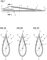
- Fig. 1 shows a schematic side view of a raw wind turbine blade 1 with three filled grooves 21 running at least with a directional component along the spanwise direction S.
- the raw wind turbine blade 1 comprises a blade tip 11 and a blade root 12, wherein the blade 1 might be fixed by a fixture in a predefined height over the ground G at the root 12 during execution of the method according to the invention.
- the blade structure is hollow with at least one cavity on the inside and comprises a shell comprising multiple layers of fiber material and core material.
- the blade 1 comprises an airfoil geometry with a pressure side 13 and a suction side 14, wherein a section of the shell associated with the pressure side 13 and a section of the shell associated with the suction side 14 meet at a leading edge 15 and a trailing edge 16.
- Fig. 2a a cross-section in the plane A-A of a raw wind turbine blade 1 is shown, wherein the grooves 2 are still unfilled which corresponds to a condition of the raw blade 1 as it is removed from a mold.
- the grooves 2 correspond to positions at which air extraction material or "filters" have been placed in the mold.
- the hardenable filler material 3 is applied to the grooves 2 so that the hollow space is completely filled which creates filled grooves 21.
- a surface of the filler material 3 might be smoothened with a spatula after filling the grooves 2 so that as little filler material 3 as possible protrudes beyond the intended airfoil geometry and/or laterally outwardly from the grooves 2. However, this cannot completely be avoided so that the filled grooves 21 still have a protruding portion 31 of filler material 3 that subsequently has to be grinded off.
- Fig. 2c shows a condition of the blade 1 after grinding, wherein the protruding portion 31 of filler material 3 has been removed from the filled grooves 21 so that the blade 1 has an ideal airfoil geometry around its full circumference.
- Fig. 3 shows a schematic side view of the raw wind turbine blade 1 of Fig. 1 during execution of the method according to the invention with a grinding apparatus 4 located sideways adjacent to the raw wind turbine blade 1.
- the filled grooves 21 are still in an unground state.
- the grinding apparatus 4 comprises a tool head 41 with at least one grinding means 411,415 (see Fig. 6 - Fig. 9 ), wherein the tool head 41 is moveable at least along the spanwise direction S of the blade 1.
- the tool head 41 is fixed to an apparatus base 42 having a drive system and wheels 43 that allow the apparatus base 42 to move along the spanwise direction S. As the apparatus base 42 moves, the tool head 41 moves with it.
- the tool head 41 is mounted at the apparatus base 42 through a support structure 44 and a tool head connector 45. One end of the tool head connector 45 is arranged at the support structure 44 and another end of the tool head connector 45 at the tool head 41.
- the support structure 44 may in particular extend essentially vertical.
- the tool head 41 is further moveable in a height direction H, wherein the required degree of freedom of movement can be provided by means of the support structure 44 and/or by means of the tool head 41. It is in particular possible that the support structure 44 comprises a linear drive system adapted to move the tool head connector 45 in height.
- a shape of the tool head 41 is adaptable at least with respect to a plane running perpendicular to the spanwise direction S so that the tool head 41 can form a cross-sectional shape representing a negative of a cross-sectional shape of the airfoil geometry of the wind turbine blade 1 at a given spanwise position.
- the grinding means 411,415 of the tool head 41 is placed on a section of a filled groove 21.
- the shape of the tool head 41 is adapted so that it corresponds with a shape of a cross-section of an airfoil geometry of the wind turbine blade 1 at the specific spanwise position. Then, the tool head 41 is moved by movement of the apparatus base 42 in the spanwise direction S so that the filler material 3 is continuously grinded from the filled groove 21.
- a height position H of the tool head is continuously adjusted to correspond with a local height position of the filled groove 21.
- the shape of the tool head 41 can be continuously adapted as the tool head 41 is moved along the spanwise direction S to always correspond with a local shape of a cross-section of the airfoil geometry of the blade 1.
- the grinding is done at the pressure side 13 of the blade 1.
- the grinding using the grinding apparatus 4 might also be done at a suction side 14 of the blade 1.
- the grinding apparatus 4 in particular the tool head 41 of the grinding apparatus 4, comprises at least one optical projection means, in particular a dot and/or line projection means, that projects a dot or line of light 46 onto an outer surface of the raw wind turbine blade 1 in at least one region laterally neighboring the filled groove 21.
- optical projection means in particular a dot and/or line projection means, that projects a dot or line of light 46 onto an outer surface of the raw wind turbine blade 1 in at least one region laterally neighboring the filled groove 21.
- the projected dot or line of light 46 on the surface of the raw wind turbine blade 1 gives an indication of the area that is to be grinded and allows to precisely reshape the tool head 41 so that the grinding is substantially limited to the filled groove 21 and a laminate structure of the raw wind turbine blade 1 outside of the filled groove 21 is not damaged by grinding.
- Fig. 4 the grinding apparatus is shown in more detail
- Fig. 5 shows Detail A of Fig. 4
- the tool head 41 can be mounted to the tool head connector 45 by means of a tool head joint 47 having at least one rotational degree of freedom of movement along the spanwise direction S. Additionally or alternatively the joint 47 or a different joint might have a rotational degree of freedom of movement along the chordwise direction C and/or along an axis running perpendicularly to both the spanwise direction S and the chordwise direction C.
- the rotational position of the tool head 41 can be continuously adapted at the joint 47 to ensure the grinding means 411,415 of the tool head 41 contacts the filled groove 21 at a given spanwise position at a predefined grinding angle.
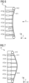
- a first embodiment of the tool head 41 is shown as a cross-section in the plane B-B of Fig. 5 , i.e. the sectional plane runs parallel to the chordwise direction C and perpendicular to the spanwise direction S.
- the tool head 41 comprises a grinding belt 411 that is mounted on pulleys 412, at least one of the pulleys being a driven pulley 412.
- the pulleys 412 rotate substantially along the spanwise direction S so that the grinding belt 411 moves in the chordwise direction C respectively along a circumferential direction of the blade 1 in an intended state of use of the grinding apparatus 4.
- the tool head 41 comprises a deformable support 414 that is coupled to multiple actuators 413a-g that are variable in length.
- a shape of the deformable support 414 can be adapted, e.g. to form a concave shape as it is shown in Fig. 6 or to form a convex shape as it is shown in Fig. 7 .
- the convexity and/or concavity in Fig. 6 and Fig. 7 are shown in an exaggerated way to illustrate the operation of the tool head 41, although the convexity and/or concavity may be less pronounced in practice.
- This adaptability of the shape of the tool head 41 allows for an efficient and high quality grinding of any cross-sectional shape along the spanwise direction of a wind turbine blade.
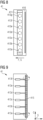
- Fig. 8 shows a bottom view of the tool head 41 of Fig. 6 and Fig. 7 from a view direction v indicated in Fig. 6 .
- the tool head 41 comprises a suction nozzle 416 that can be coupled to a vacuum source when the grinding apparatus 4 is used.
- Fig. 9 shows a different embodiment of a tool head 41 that does not comprise a grinding belt but rotatable grinding heads 415. Other than the grinding belt the rotatable grinding heads 415 are rotatable along the chordwise direction C.
- the tool head 41 of the second embodiment equally comprises multiple actuators 413a-f that are variable in length in order to adapt the shape of the tool head 41.
- Fig. 10 shows a flow chart of an embodiment of the method according to the invention.
- the method comprises the following steps:
Landscapes
- Engineering & Computer Science (AREA)
- Mechanical Engineering (AREA)
- Chemical & Material Sciences (AREA)
- Manufacturing & Machinery (AREA)
- Materials Engineering (AREA)
- Sustainable Development (AREA)
- Life Sciences & Earth Sciences (AREA)
- Sustainable Energy (AREA)
- Combustion & Propulsion (AREA)
- General Engineering & Computer Science (AREA)
- Composite Materials (AREA)
- Grinding And Polishing Of Tertiary Curved Surfaces And Surfaces With Complex Shapes (AREA)
- Finish Polishing, Edge Sharpening, And Grinding By Specific Grinding Devices (AREA)
- Wind Motors (AREA)
Abstract
A method for manufacturing a wind turbine blade, comprising the steps
a) Manufacturing a raw wind turbine blade (1) by lamination of one or multiple layers of fiber material, wherein the raw wind turbine blade (1) comprises at least one groove (2) running at least with a directional component along a spanwise direction (S);
b) Filling the at least one groove (2) with a hardenable filler material (3) so that a filled groove (21) is provided;
c) Providing a grinding apparatus (4)
- comprising a tool head (41) with at least one grinding means (411, 415),
- wherein the tool head (41) is moveable at least along the
spanwise direction (S),
- and wherein a shape of the tool head (41) is adaptable at
least with respect to a plane running perpendicular to the
spanwise direction (S);
d) Placing the grinding means (411,415) of the tool head (41) on a section of the filled groove (21);
e) Adapting the shape of the tool head (41) so that it corresponds with a shape of a cross-section of an airfoil geometry of the wind turbine blade at a given spanwise position;
f) Moving the tool head (41) in the spanwise direction (S), thereby continuously grinding of filler material (3) with the grinding means (411,415).
a) Manufacturing a raw wind turbine blade (1) by lamination of one or multiple layers of fiber material, wherein the raw wind turbine blade (1) comprises at least one groove (2) running at least with a directional component along a spanwise direction (S);
b) Filling the at least one groove (2) with a hardenable filler material (3) so that a filled groove (21) is provided;
c) Providing a grinding apparatus (4)
- comprising a tool head (41) with at least one grinding means (411, 415),
- wherein the tool head (41) is moveable at least along the
spanwise direction (S),
- and wherein a shape of the tool head (41) is adaptable at
least with respect to a plane running perpendicular to the
spanwise direction (S);
d) Placing the grinding means (411,415) of the tool head (41) on a section of the filled groove (21);
e) Adapting the shape of the tool head (41) so that it corresponds with a shape of a cross-section of an airfoil geometry of the wind turbine blade at a given spanwise position;
f) Moving the tool head (41) in the spanwise direction (S), thereby continuously grinding of filler material (3) with the grinding means (411,415).
The method allows for an automation of currently manually executed grinding steps and thus both increases production speed and lowers costs for wind turbine blades.
Description
- The present invention relates to a method for manufacturing a wind turbine blade or wind turbine blade section and to a grinding apparatus for grinding a grinding area of a raw wind turbine blade or raw wind turbine blade section, the grinding area having an extension along a spanwise direction of the raw wind turbine blade or raw wind turbine blade section and a convex or concave curved cross-section.
- Wind turbine blades, especially for offshore use, with the evolvement of technology continuously increase in size. Regarding the main dimensions current blades can reach a root diameter of approximately 4m, a blade length of well over 100m while typical chord lengths can reach up to 7m or even more. Although the dimensions are literally tremendous the production of wind turbine blades still includes many steps that require manual labor. A major portion of the manual labor is represented by grinding work at the outer surface of the blade.
- Typically, wind turbine blades are manufactured by lamination of multiple layers of fiber material in a mold having the shape of a negative impression of the outer blade geometry.
- One approach including a transversal fiber material layup is the IntegralBlade® technology that is described in detail in
EP 1 310 351 A1 - A typical fiber material layup in a mold includes one or multiple air extraction means that are adapted to extract excess air from the mold before and/or during resin infusion of the fiber material layup. The air extraction means do not become part of the final blade structure but are an auxiliary production tool. Typical air extraction means include semipermeable membranes, i.e. membranes that allow gases, in particular air, to pass and block the passage of liquids, in particular resin. The permeable membranes are connected to a vacuum source located externally of the mold so that excess air from the mold can be extracted therefrom. Sometimes such air extraction means are also referred to as "filters".
- The air extraction means are typically placed in the mold with an extension along a spanwise or longitudinal direction so that the raw wind turbine blade after removing it from the mold has grooves at its outer surface running along the spanwise or longitudinal direction at the positions where the air extraction means have been placed in the mold.
- These grooves have to be filled with a hardenable filler material to restore the intended airfoil geometry of the final wind turbine blade. After application and hardening of the filler material excess filler material, e.g. residual filler material protruding beyond the intended airfoil geometry and/or laterally outwardly from the groove, has to be ground off. This is currently done by manual labor which, depending on the concrete dimensions of the blade, may take over 60 man-hours which is unproductive and expensive.
- But manual grinding steps are not only disadvantageous from a productivity perspective. As the grinding is mainly done in an overhead position the execution of these manual labor steps means an enormous physical strain for the workers. Additionally, the particles generated by grinding mean a health risk. As most jurisdictions impose various limitations with regards to labor safety (e.g. ergonomics specifications, lifting weights for overhead work, air quality) on employers the retention of the manual labor steps implies a barrier for both the dimensions of the blades that can be produced and for any potential productivity gains.
- Additionally, as said grooves are typically located in either convex or concave curved cross-sections of the blade, it is not easy for workers doing the manual grinding to maintain the intended airfoil geometry of the blade without compromising it. However, a near target shape of the airfoil geometry is of utmost importance as deviations therefrom can lead to performance losses of the blade, e.g. in the form of increased drag and/or reduced lift.
- Therefore it is one object of the present invention to provide a method for manufacturing a wind turbine blade or wind turbine blade section that eliminates above technical disadvantages and allows for a further automation of the production and thus both increases production speed and lowers costs.
- It is a further object of the present invention to provide a grinding apparatus for grinding a grinding area of a raw wind turbine blade or raw wind turbine blade section that allows for an automation of grinding steps that are currently executed as manual labor steps.
- Accordingly, a method for manufacturing a wind turbine blade or wind turbine blade section is proposed.
- The method comprises the following steps:
- a) Manufacturing a raw wind turbine blade or raw wind turbine blade section by lamination of one or multiple layers of fiber material, wherein the raw wind turbine blade or raw wind turbine blade section comprises at least one groove running at least with a directional component along a spanwise direction;
- b) Filling the at least one groove with a hardenable filler material that is subsequently hardened so that at least one filled groove is provided;
- c) Providing a grinding apparatus
- comprising a tool head with at least one grinding means,
- wherein the tool head is moveable at least along the spanwise direction,
- and wherein a shape of the tool head is adaptable at least with respect to a plane running perpendicular to the
- d) Placing the grinding means of the tool head on a section of the filled groove;
- e) Adapting the shape of the tool head so that it corresponds with a shape of a cross-section of an airfoil geometry of the wind turbine blade or wind turbine blade section at a given spanwise position;
- f) Moving the tool head in the spanwise direction, thereby continuously grinding of the filler material with the grinding means.
- The raw wind turbine blade or raw wind turbine blade section might also be referred to as "green wind turbine blade" or "green wind turbine blade section". "Raw" herein in particular having the meaning of unfinished, in particular without a final surface coating applied to an outer surface.
- The at least one groove might in particular have a depth between 1 mm and 10 mm, in particular between 2 mm and 5 mm. The at least one groove might be the result of previous process steps, in particular it might represent a negative impression of a volume in that air extraction means or "filters" have been placed in a mold for lamination of the raw wind turbine blade or raw wind turbine blade section.
- The hardenable filler material might comprise a suitable plastic material and can be provided in a paste-like state with a relatively high viscosity so that it sticks to the groove and does not flow away under the influence of gravity.
- The hardenable filler material might in particular comprise a 2 component system, in particular a 2 component epoxy system.
- The filler material applied to the groove in step b) might slightly protrude above a cross-section of the airfoil geometry of the final wind turbine blade or wind turbine blade section which is ground off in step f) to bring the blade back to its target airfoil geometry.
- The adaption of the shape of the tool head ensures that filled grooves located in convex and/or concave cross-sections of the raw wind turbine blade or raw wind turbine blade section can be grinded in the best possible way, i.e. without compromising the airfoil shape and without grinding the structure of the raw wind turbine blade or raw wind turbine blade section in regions laterally neighboring the filled groove which could harm the laminate structure. In other words, adaption of the shape of the tool head to a shape of a cross-section of an airfoil geometry of the wind turbine blade or wind turbine blade section at a given spanwise position ensures that the grinding only happens where it is supposed to happen, namely limited to the filled groove, and that the shape of the airfoil geometry is not compromised by the grinding as the tool head forms a negative shape of the airfoil geometry of the blade at a given spanwise position in a cross-section where the filled groove is located.
- In embodiments the tool head might comprise a support for the grinding means. The support can in particular be deformable so that its shape is actively adjustable to adapt the shape of a contact surface between tool head and a blade surface. The support may comprise one or multiple moveable elements, for example rollers, which are adapted to transfer forces to the grinding means as the grinding means is under grinding movement.
- The grinding means can be rotatable around the spanwise direction or chordwise direction of the raw wind turbine blade or raw wind turbine blade section, wherein in particular the grinding means comprises at least one belt sander or rotatable grinding head. A grinding speed, e.g. rotational speed, of the grinding means can be controlled. Additionally or alternatively, a feed speed with that the tool head is moved along the spanwise direction in step f) can be controlled as well.
- Advantageously, the method according to the invention allows to grind the filled grooves fully automatic without the need for manual labor. This allows for significant productivity gains in the production of wind turbine blades as the grinding apparatus used in the method according to the invention can perform the grinding quicker and with less downtime and/or without breaks. Additionally, the method is also beneficial under a Health Safety Environment (HSE) perspective as overhead works in dust loaded environments are avoided. An operator controlling the equipment used in the method according to the invention might do this remote from the grinding site in a clean environment. Further, the method according to the invention allows for a more consistent grinding quality as human errors are eliminated through the automation of the grinding process.
- According to a further embodiment, the shape of the tool head of the grinding apparatus is continuously adapted in step f) as the tool head is moved along the spanwise direction to correspond with a local shape of a cross-section of the airfoil geometry of the wind turbine blade or wind turbine blade section.
- According to a further embodiment, the tool head of the grinding apparatus is moveable in a height direction with respect to an intended state of use of the grinding apparatus and wherein step f) comprises continuously adjusting a height position of the tool head as the tool head is moved along the spanwise direction to correspond with a local height position of the filled groove. Depending on the type of blade or blade section, typical heights at that the filled grooves are located during the grinding process may reach from 3 m to 6 m.
- According to yet a further embodiment, the raw wind turbine blade or raw wind turbine blade section is fixed by a fixture in a predefined height over the ground so that the spanwise direction runs essentially parallel to the ground, wherein in particular a suction side and/or pressure side of the raw wind turbine blade or raw wind turbine blade section are located sidewards.
- Such a fixture might in particular be fixed to a root section of the raw wind turbine blade or blade section. In particular the fixture can allow for a rotational movement of the raw wind turbine blade or blade section along the spanwise direction.
- According to a further embodiment, steps d) to f) are executed at a pressure side and/or a suction side of the raw wind turbine blade or raw wind turbine blade section, i.e. in particular from the sides of the raw wind turbine blade or raw wind turbine blade section. Alternatively or additionally, the grinding apparatus can be located sideways adjacent to the raw wind turbine blade or raw wind turbine blade section, in particular during execution of the method steps d) to f).
- The raw wind turbine blade or blade section might comprise more than one groove running at least with a directional component along a spanwise direction, for example at least one groove at a suction side and at least one groove at the pressure side and/or multiple grooves at the suction side and/or pressure side. Grinding of grooves at the pressure side and the suction side may be done serially or simultaneously, wherein separate grinding apparatuses can be located sideways adjacent to the raw wind turbine blade or raw wind turbine blade section at the pressure side and the suction side. Multiple grooves at the pressure side or the suction side might be grinded serially or simultaneously, e.g. by using separate grinding apparatuses which are spaced along the spanwise direction of the blade.
- According to yet a further embodiment, the tool head of the grinding apparatus is rotatable at least along one axis, wherein the at least one axis in particular runs parallel to the spanwise direction of the raw wind turbine blade or raw wind turbine blade section. It is in particular possible that step f) includes continuously adapting a rotational position of the tool head as the tool head is moved along the spanwise direction to ensure the grinding means of the tool head contacts the filled groove at a given spanwise position at a predefined grinding angle.
- The tool head might have other rotational degrees of freedom of movement as well, e.g. other possible rotational axes are axes running perpendicularly to the spanwise direction, for example an axis running parallel to the chordwise direction and/or an axis being both oriented perpendicularly to the spanwise and the chordwise direction. By providing the tool head with rotational degrees of freedom of movement the tool head can even better adapt to a shape of a cross-section of an airfoil geometry of the wind turbine blade or wind turbine blade section at a given spanwise position. Additionally, adaption of the grinding angle allows to make use of the grinding means in the most effective way, e.g. to ensure homogeneous wear.
- According to a further embodiment, the tool head of the grinding apparatus comprises multiple actuators arranged spaced apart along a circumferential direction of the raw wind turbine blade or raw wind turbine blade section, wherein the actuators are each adapted to locally apply a force on the grinding means, and wherein the actuators are used in step d) and/or f) to adapt the shape of the tool head.
- For example, the actuators can comprise pneumatic or hydraulic pressure cylinders. Alternatively, the actuators may comprise fluid tight expansion pockets that can be individually inflated by a pressurized fluid. Yet alternatively, the actuators may comprise electrical actuators, such as stepper motors. It is in particular possible that the actuators are mechanically connected to the support for the grinding means, the shape of which is actively adjusted by the actuators to adapt the shape of a contact surface between tool head and a blade surface.
- In embodiments the grinding apparatus can comprise at least one processing means adapted to individually control at least the actuators and/or the height position of the tool head.
- The processing means may be implemented in hardware and/or in software. If said entity is implemented in hardware, it may be embodied as a device, e.g. as a computer or as a processor or as a part of a system, e.g. a computer system. If said entity is implemented in software it may be embodied as a computer program product, as a function, as a routine, as a program code or as an executable object.
- Alternatively or additionally, the processing means can be adapted to also control the grinding speed of the grinding means and/or the feed speed of the tool head.
- According to another embodiment, the grinding apparatus, in particular the tool head of the grinding apparatus, comprises at least one optical projection means, in particular a dot and/or line projection means, adapted to project a dot or line of light onto an outer surface of the raw wind turbine blade or raw wind turbine blade section in at least one region laterally neighboring the filled groove. Additionally, the grinding apparatus, in particular the tool head of the grinding apparatus, comprises at least one optical sensor adapted to detect said projected dot or line of light on the surface of the raw wind turbine blade or raw wind turbine blade section, wherein said optical sensor is operably coupled to the processing means.
- In step d) and/or f) data from the optical sensor may be processed by the processing means to adapt the shape of the tool head by individually controlling the multiple actuators to ensure that substantially only the filled groove is grinded and/or to adjust a height position of the tool head.
- In embodiments, an optical projection means can in particular include a laser and/or other types of focused light sources.
- The projected dot or line of light on the surface of the raw wind turbine blade or raw wind turbine blade section gives an indication of the area that is to be grinded with the grinding tool and allows the actuators to be retracted to reduce pressure on the grinding means in regions located laterally outwardly therefrom. This significantly helps to ensure that the laminate structure of the raw wind turbine blade or raw wind turbine blade section outside of the filled groove is not damaged by grinding.
- According to yet another embodiment, the grinding apparatus, in particular the tool head of the grinding apparatus, comprises at least one camera and/or at least one distance sensor and/or at least one gloss meter and/or at least one 3D-scanner. The at least one camera and/or at least one distance sensor and/or at least one gloss meter and/or at least one 3D-scanner can be in particular operably coupled to the processing means, wherein in step d) and/or f) data from the at least one camera and/or at least one distance sensor and/or at least one gloss meter and/or at least one 3D-scanner can be processed by the processing means to adapt the shape of the tool head by individually controlling the multiple actuators to ensure that substantially only the filled groove is grinded and/or to adjust a height position of the tool head.
- Alternatively, the at least one camera and/or at least one distance sensor and/or at least one gloss meter and/or at least one 3D-scanner can be used to continuously monitor a grinding quality in step f) wherein it is in particular possible that based on data from the at least one camera and/or at least one distance sensor and/or at least one gloss meter and/or at least one 3D-scanner grinding parameters like the grinding speed of the grinding tool and/or the feed speed of the tool head in the spanwise direction are controlled to ensure a target grinding quality.
- The processing means might comprise software that comprises self-learning algorithms and/or components of artificial intelligence (AI) that learn based on control interventions in the past.
- According to a further embodiment, the grinding apparatus comprises a processing means operably coupled with at least one data source, wherein the data source comprises data describing a three-dimensional shape of an outer surface of the wind turbine blade or wind turbine blade section, wherein in step f) the tool head is moved along the spanwise direction under continuous adaption of the height position of the tool head and/or under continuous adaption of the shape of the tool head based on said data.
- The data describing a three-dimensional shape of an outer surface of the wind turbine blade or wind turbine blade section might in particular be stored in the data source as a typical 3D-CAD file, e.g. a Step-file or similar file formats that the skilled person deems appropriate.
- In other embodiments, certain process parameters, e.g. the height position of the tool head, the grinding speed of the grinding means, the feed speed of the tool head and/or the shape of the tool head might be controlled by an operator of the grinding apparatus by a human-machine interface provided by the grinding apparatus.
- According to a second aspect, a grinding apparatus for grinding a grinding area of a raw wind turbine blade or raw wind turbine blade section, in particular for use in a method according to the first aspect of the invention, is proposed. The grinding area having an extension along a spanwise direction of the raw wind turbine blade or raw wind turbine blade section and a convex or concave curved cross-section.
- The grinding apparatus comprises:
- a tool head with at least one grinding means,
- wherein the tool head is moveable at least along the spanwise direction of the raw wind turbine blade or raw wind turbine blade section,
- and wherein a shape of the tool head is adaptable at least with respect to a plane running perpendicular to a spanwise direction of the raw wind turbine blade or raw wind turbine blade section.
- According to a further embodiment, the tool head is mounted to an apparatus base that is moveable on the ground, wherein in particular the apparatus base comprises a drive system and wheels that allows movement of the apparatus base in the spanwise direction of the raw wind turbine blade or raw wind turbine blade section. The drive system allows the apparatus base to be moved with a preset and/or controlled feed speed along the spanwise direction of the blade or blade section.
- The tool head may be fixed to the apparatus base so that the tool head can in particular be moved together with the apparatus base. The apparatus base may be either mounted on rails on the ground or the wheels may be placed directly on the ground. In the latter case the drive system may include a guiding system, e.g. an optical guiding system with guide markings on the ground, to direct the movement of the apparatus base along an intended path along the spanwise direction of the blade or blade section.
- Alternatively, the tool head may be mounted at a crane or gantry system above the raw wind turbine blade or raw wind turbine blade section in an intended state of use of the grinding apparatus, wherein the crane or gantry system allows movement of the tool head in the spanwise direction of the raw wind turbine blade or raw wind turbine blade section.
- According to another embodiment, the grinding means is rotatable around the spanwise direction or chordwise direction of the raw wind turbine blade or raw wind turbine blade section in an intended state of use of the grinding apparatus, wherein in particular the grinding means comprises at least one belt sander or rotatable grinding head.
- An extension of the grinding means along the circumferential direction of the blade or blade section in an intended state of use of the grinding apparatus may reach from 40 cm to 150 cm, in particular from 60 cm to 120 cm.
- Lastly, the tool head may comprise at least one suction nozzle connectable to a vacuum source for dust extraction from the grinding means.
- The embodiments and features described with reference to the method of the present invention apply mutatis mutandis to the apparatus of the present invention and vice versa.
- Further possible implementations or alternative solutions of the invention also encompass combinations - that are not explicitly mentioned herein - of features described above or below with regard to the embodiments. The person skilled in the art may also add individual or isolated aspects and features to the most basic form of the invention.
- Further embodiments, features and advantages of the present invention will become apparent from the subsequent description and dependent claims, taken in conjunction with the accompanying drawings, in which:
-
Fig. 1 shows a schematic side view of a raw wind turbine blade with filled grooves running at least with a directional component along a spanwise direction; -
Fig. 2a shows cross-section A-A ofFig. 1 of a raw wind turbine blade with unfilled grooves; -
Fig. 2b shows cross-section A-A ofFig. 1 of a raw wind turbine blade with filled grooves before grinding; -
Fig. 2c shows cross-section A-A ofFig. 1 of a raw wind turbine blade with filled grooves after grinding; -
Fig. 3 shows a schematic side view of the raw wind turbine blade ofFig. 1 during execution of the method according to the invention with a grinding apparatus located sideways adjacent to the raw wind turbine blade; -
Fig. 4 shows a schematic view of a grinding apparatus according to the invention; -
Fig. 5 shows the tool head of the grinding apparatus as Detail A according toFig. 4 ; -
Fig. 6 shows the tool head of the grinding apparatus as cross-section B-B according toFig. 5 , the tool head in a concave shape; -
Fig. 7 shows the tool head of the grinding apparatus as cross-section B-B according toFig. 5 , the tool head in a convex shape; -
Fig. 8 shows a bottom view of the tool head ofFig. 6 and Fig. 7 ; -
Fig. 9 shows a different tool head of the grinding apparatus as cross-section B-B according toFig. 5 , the tool head in a flat shape and -
Fig. 10 shows a flow chart of an embodiment of the method according to the invention. - In the Figures, like reference numerals designate like or functionally equivalent elements, unless otherwise indicated.
-
Fig. 1 shows a schematic side view of a rawwind turbine blade 1 with three filledgrooves 21 running at least with a directional component along the spanwise direction S. The rawwind turbine blade 1 comprises ablade tip 11 and ablade root 12, wherein theblade 1 might be fixed by a fixture in a predefined height over the ground G at theroot 12 during execution of the method according to the invention. The blade structure is hollow with at least one cavity on the inside and comprises a shell comprising multiple layers of fiber material and core material. Theblade 1 comprises an airfoil geometry with apressure side 13 and asuction side 14, wherein a section of the shell associated with thepressure side 13 and a section of the shell associated with thesuction side 14 meet at aleading edge 15 and a trailingedge 16. - In
Fig. 2a a cross-section in the plane A-A of a rawwind turbine blade 1 is shown, wherein thegrooves 2 are still unfilled which corresponds to a condition of theraw blade 1 as it is removed from a mold. Thegrooves 2 correspond to positions at which air extraction material or "filters" have been placed in the mold. As thegrooves 2 form deviations from an ideal airfoil geometry they are subsequently filled with a hardenable filler material having a past-like consistency, which is shown inFig. 2b . - The hardenable filler material 3 is applied to the
grooves 2 so that the hollow space is completely filled which creates filledgrooves 21. A surface of the filler material 3 might be smoothened with a spatula after filling thegrooves 2 so that as little filler material 3 as possible protrudes beyond the intended airfoil geometry and/or laterally outwardly from thegrooves 2. However, this cannot completely be avoided so that the filledgrooves 21 still have a protrudingportion 31 of filler material 3 that subsequently has to be grinded off. -
Fig. 2c shows a condition of theblade 1 after grinding, wherein the protrudingportion 31 of filler material 3 has been removed from the filledgrooves 21 so that theblade 1 has an ideal airfoil geometry around its full circumference. -
Fig. 3 shows a schematic side view of the rawwind turbine blade 1 ofFig. 1 during execution of the method according to the invention with a grinding apparatus 4 located sideways adjacent to the rawwind turbine blade 1. The filledgrooves 21 are still in an unground state. - The grinding apparatus 4 comprises a
tool head 41 with at least one grinding means 411,415 (seeFig. 6 - Fig. 9 ), wherein thetool head 41 is moveable at least along the spanwise direction S of theblade 1. Thetool head 41 is fixed to anapparatus base 42 having a drive system andwheels 43 that allow theapparatus base 42 to move along the spanwise direction S. As theapparatus base 42 moves, thetool head 41 moves with it. Thetool head 41 is mounted at theapparatus base 42 through asupport structure 44 and atool head connector 45. One end of thetool head connector 45 is arranged at thesupport structure 44 and another end of thetool head connector 45 at thetool head 41. Thesupport structure 44 may in particular extend essentially vertical. - The
tool head 41 is further moveable in a height direction H, wherein the required degree of freedom of movement can be provided by means of thesupport structure 44 and/or by means of thetool head 41. It is in particular possible that thesupport structure 44 comprises a linear drive system adapted to move thetool head connector 45 in height. - A shape of the
tool head 41 is adaptable at least with respect to a plane running perpendicular to the spanwise direction S so that thetool head 41 can form a cross-sectional shape representing a negative of a cross-sectional shape of the airfoil geometry of thewind turbine blade 1 at a given spanwise position. - In order to initiate the grinding process, the grinding means 411,415 of the
tool head 41 is placed on a section of a filledgroove 21. Before or after, the shape of thetool head 41 is adapted so that it corresponds with a shape of a cross-section of an airfoil geometry of thewind turbine blade 1 at the specific spanwise position. Then, thetool head 41 is moved by movement of theapparatus base 42 in the spanwise direction S so that the filler material 3 is continuously grinded from the filledgroove 21. - As the
tool head 41 is moved along the spanwise direction S a height position H of the tool head is continuously adjusted to correspond with a local height position of the filledgroove 21. - As the
blade 1 has variable cross-sections along the spanwise direction S and additionally might be twisted, the shape of thetool head 41 can be continuously adapted as thetool head 41 is moved along the spanwise direction S to always correspond with a local shape of a cross-section of the airfoil geometry of theblade 1. - In the shown embodiment the grinding is done at the
pressure side 13 of theblade 1. In other embodiments - which are not shown in the Figures - the grinding using the grinding apparatus 4 might also be done at asuction side 14 of theblade 1. - Further, the grinding apparatus 4, in particular the
tool head 41 of the grinding apparatus 4, comprises at least one optical projection means, in particular a dot and/or line projection means, that projects a dot or line oflight 46 onto an outer surface of the rawwind turbine blade 1 in at least one region laterally neighboring the filledgroove 21. - The projected dot or line of
light 46 on the surface of the rawwind turbine blade 1 gives an indication of the area that is to be grinded and allows to precisely reshape thetool head 41 so that the grinding is substantially limited to the filledgroove 21 and a laminate structure of the rawwind turbine blade 1 outside of the filledgroove 21 is not damaged by grinding. - In
Fig. 4 the grinding apparatus is shown in more detail, whereasFig. 5 shows Detail A ofFig. 4 . Thetool head 41 can be mounted to thetool head connector 45 by means of a tool head joint 47 having at least one rotational degree of freedom of movement along the spanwise direction S. Additionally or alternatively the joint 47 or a different joint might have a rotational degree of freedom of movement along the chordwise direction C and/or along an axis running perpendicularly to both the spanwise direction S and the chordwise direction C. As thetool head 41 is moved along the spanwise direction S the rotational position of thetool head 41 can be continuously adapted at the joint 47 to ensure the grinding means 411,415 of thetool head 41 contacts the filledgroove 21 at a given spanwise position at a predefined grinding angle. - In
Fig. 6 a first embodiment of thetool head 41 is shown as a cross-section in the plane B-B ofFig. 5 , i.e. the sectional plane runs parallel to the chordwise direction C and perpendicular to the spanwise direction S. Thetool head 41 comprises a grindingbelt 411 that is mounted onpulleys 412, at least one of the pulleys being a drivenpulley 412. Thepulleys 412 rotate substantially along the spanwise direction S so that the grindingbelt 411 moves in the chordwise direction C respectively along a circumferential direction of theblade 1 in an intended state of use of the grinding apparatus 4. Beneath the grindingbelt 411 thetool head 41 comprises adeformable support 414 that is coupled tomultiple actuators 413a-g that are variable in length. By individually controlling the length of theactuators 413a-g a shape of thedeformable support 414 can be adapted, e.g. to form a concave shape as it is shown inFig. 6 or to form a convex shape as it is shown inFig. 7 . The convexity and/or concavity inFig. 6 and Fig. 7 are shown in an exaggerated way to illustrate the operation of thetool head 41, although the convexity and/or concavity may be less pronounced in practice. - This adaptability of the shape of the
tool head 41 allows for an efficient and high quality grinding of any cross-sectional shape along the spanwise direction of a wind turbine blade. -
Fig. 8 shows a bottom view of thetool head 41 ofFig. 6 and Fig. 7 from a view direction v indicated inFig. 6 . Next to the grindingbelt 411 in the spanwise direction S thetool head 41 comprises asuction nozzle 416 that can be coupled to a vacuum source when the grinding apparatus 4 is used. -
Fig. 9 shows a different embodiment of atool head 41 that does not comprise a grinding belt but rotatable grinding heads 415. Other than the grinding belt the rotatable grinding heads 415 are rotatable along the chordwise direction C. Thetool head 41 of the second embodiment equally comprisesmultiple actuators 413a-f that are variable in length in order to adapt the shape of thetool head 41. - Lastly,
Fig. 10 shows a flow chart of an embodiment of the method according to the invention. - The method comprises the following steps:
- a) Manufacturing a raw
wind turbine blade 1 or raw wind turbine blade section by lamination of one or multiple layers of fiber material, wherein the rawwind turbine blade 1 or raw wind turbine blade section comprises at least onegroove 2 running at least with a directional component along a spanwise direction S; - b) Filling the at least one
groove 2 with a hardenable filler material 3 that is subsequently hardened so that at least one filledgroove 21 is provided; - c) Providing a grinding apparatus 4
- comprising a
tool head 41 with at least one grinding means 411, 415, - wherein the
tool head 41 is moveable at least along the spanwise direction S, - and wherein a shape of the
tool head 41 is adaptable at least with respect to a plane running perpendicular to the
- comprising a
- d) Placing the grinding means 411,415 of the
tool head 41 on a section of the filledgroove 21; - e) Adapting the shape of the
tool head 41 so that it corresponds with a shape of a cross-section of an airfoil geometry of the wind turbine blade or wind turbine blade section at a given spanwise position; - f) Moving the
tool head 41 in the spanwise direction S, thereby continuously grinding the filler material 3 with the grinding means 411, 415 from the filledgroove 21. - Although the present invention has been described in accordance with preferred embodiments, it is obvious for the person skilled in the art that modifications are possible in all embodiments.
- Independent of the grammatical term usage, individuals with male, female or other gender identities are included within the term.
Claims (15)
- Method for manufacturing a wind turbine blade or wind turbine blade section, comprising the stepsa) Manufacturing a raw wind turbine blade (1) or raw wind turbine blade section by lamination of one or multiple layers of fiber material, wherein the raw wind turbine blade (1) or raw wind turbine blade section comprises at least one groove (2) running at least with a directional component along a spanwise direction (S);b) Filling the at least one groove (2) with a hardenable filler material (3) that is subsequently hardened so that at least one filled groove (21) is provided;c) Providing a grinding apparatus (4)- comprising a tool head (41) with at least one grinding means (411, 415),- wherein the tool head (41) is moveable at least along the
spanwise direction (S),- and wherein a shape of the tool head (41) is adaptable atleast with respect to a plane running perpendicular to thespanwise direction (S);d) Placing the grinding means (411,415) of the tool head (41) on a section of the filled groove (21);e) Adapting the shape of the tool head (41) so that it corresponds with a shape of a cross-section of an airfoil geometry of the wind turbine blade or wind turbine blade section at a given spanwise position;f) Moving the tool head (41) in the spanwise direction (S), thereby continuously grinding the filler material (3) with the grinding means (411,415). - Method according to claim 1, wherein the shape of the tool head (41) of the grinding apparatus (4) is continuously adapted in step f) as the tool head (41) is moved along the spanwise direction (S) to correspond with a local shape of a cross-section of the airfoil geometry of the wind turbine blade or wind turbine blade section.
- Method according to claim 1 or 2, wherein the tool head (41) of the grinding apparatus (4) is moveable in a height direction (H) with respect to an intended state of use of the grinding apparatus (4) and wherein step f) comprises continuously adjusting a height position (H) of the tool head (41) as the tool head (41) is moved along the spanwise direction (S) to correspond with a local height position of the filled groove (21).
- Method according to any of the claims 1 to 3, wherein the raw wind turbine blade (1) or raw wind turbine blade section is fixed by a fixture in a predefined height over the ground (G) so that the spanwise direction (S) runs essentially parallel to the ground (G), wherein in particular a suction side (14) and/or pressure side (13) of the raw wind turbine blade (1) or raw wind turbine blade section are located sidewards.
- Method according to claim 4, wherein steps d) to f) are executed at a pressure side (13) and/or a suction side (14) of the raw wind turbine blade (1) or raw wind turbine blade section
and/or wherein the grinding apparatus (4) is located sideways adjacent to the raw wind turbine blade (1) or raw wind turbine blade section. - Method according to any of the preceding claims, wherein the tool head (41) of the grinding apparatus (4) is rotatable at least along one axis, wherein the at least one axis in particular runs parallel to the spanwise direction (S) of the raw wind turbine blade (1) or raw wind turbine blade section, and wherein in particular step f) includes continuously adapting a rotational position of the tool head (41) as the tool head (41) is moved along the spanwise direction (S) to ensure the grinding means (411,415) of the tool head (41) contacts the filled groove (21) at a given spanwise position at a predefined grinding angle.
- Method according to any of the preceding claims, wherein the tool head (41) of the grinding apparatus (4) comprises multiple actuators (413a-g) arranged spaced apart along a circumferential direction of the raw wind turbine blade (1) or raw wind turbine blade section, wherein the actuators (413a-g) are each adapted to locally apply a force on the grinding means (411,415), and wherein the actuators (413a-g) are used in step d) and/or f) to adapt the shape of the tool head (41).
- Method according to claim 7, wherein the grinding apparatus (4) comprises at least one processing means adapted to at least individually control the actuators (413a-g) and/or the height position (H) of the tool head (41).
- Method according to claim 8, wherein the grinding apparatus (4), in particular the tool head (41) of the grinding apparatus (4), comprises- at least one optical projection means, in particular a dot and/or line projection means, adapted to project a dot or line of light (46) onto an outer surface of the raw wind turbine blade (1) or raw wind turbine blade section in at least one region laterally neighboring the filled groove (21),- and at least one optical sensor adapted to detect said projected dot or line of light (46) on the surface of the raw wind turbine blade (1) or raw wind turbine blade section,- wherein said optical sensor is operably coupled to the processing means,wherein in step d) and/or f) data from the optical sensor is processed by the processing means to adapt the shape of the tool head (41) by individually controlling the multiple actuators (413a-g) to ensure that substantially only the filled groove (21) is grinded and/or to adjust a height position (H) of the tool head (41).
- Method according to any of the preceding claims,wherein the grinding apparatus (4), in particular the tool head (41) of the grinding apparatus (4), comprises at least one camera and/or at least one distance sensor and/or at least one gloss meter,wherein the at least one camera and/or at least one distance sensor and/or at least one gloss meter are operably coupled to the processing means and wherein in step d) and/or f) data from the at least one camera and/or at least one distance sensor and/or at least one gloss meter is processed by the processing means to adapt the shape of the tool head (41) by individually controlling the multiple actuators (413a-g) to ensure that substantially only the filled groove (21) is grinded and/or to adjust a height position (H) of the tool head (41).
- Method according to any of the preceding claims, wherein the grinding apparatus (4) comprises a processing means operably coupled with at least one data source, wherein the data source comprises data describing a three-dimensional shape of an outer surface of the wind turbine blade or wind turbine blade section, wherein in step f) the tool head (41) is moved along the spanwise direction (S) under continuous adaption of the height position (H) of the tool head (41) and/or under continuous adaption of the shape of the tool head (41) based on said data.
- Grinding apparatus (4) for grinding a grinding area of a raw wind turbine blade (1) or raw wind turbine blade section, the grinding area having an extension along a spanwise direction (S) of the raw wind turbine blade (1) or raw wind turbine blade section and a convex or concave curved cross-section, in particular for use in a method according to any of the preceding claims,
the grinding apparatus comprising:- a tool head (41) with at least one grinding means (411, 415),- wherein the tool head (41) is moveable at least along thespanwise direction (S) of the raw wind turbine blade (1) orraw wind turbine blade section,- and wherein a shape of the tool head (41) is adaptable atleast with respect to a plane running perpendicular to a spanwise direction (S) of the raw wind turbine blade (1)
orraw wind turbine blade section. - Grinding apparatus (4) according to claim 12,- wherein the tool head (41) is mounted to an apparatus base (42) that is moveable on the ground (G), wherein in particular the apparatus base (42) comprises a drive system and wheels (43) that allow movement of the apparatus base (42) in the spanwise direction (S) of the raw wind turbine blade (1) or raw wind turbine blade section or- wherein the tool head (41) is mounted at a crane or gantry system above the raw wind turbine blade (1) or raw wind turbine blade section in an intended state of use of the grinding apparatus (4), wherein the crane or gantry system allows movement of the tool head (41) in the spanwise direction (S) of the raw wind turbine blade (1) or raw wind turbine blade section.
- Grinding apparatus (4) according to claim 12 or 13, wherein the grinding means (411, 415) is rotatable around the spanwise direction (S) or chordwise direction (C) of the raw wind turbine blade (1) or raw wind turbine blade section in an intended state of use of the grinding apparatus (4), wherein in particular the grinding means (411, 415) comprises at least one belt sander (411) or rotatable grinding head (415) .
- Grinding apparatus (4) according to any of the claims 12 to 14, wherein the tool head (41) comprises at least one suction nozzle (416) connectable to a vacuum source for dust extraction from the grinding means (411, 415).
Priority Applications (5)
| Application Number | Priority Date | Filing Date | Title |
|---|---|---|---|
| EP23194289.7A EP4516494A1 (en) | 2023-08-30 | 2023-08-30 | Method for manufacturing a wind turbine blade or wind turbine blade section and grinding apparatus |
| CN202480055123.7A CN121752424A (en) | 2023-08-30 | 2024-08-12 | Method and grinding device for producing a wind turbine blade or a wind turbine blade section |
| PCT/EP2024/072740 WO2025045575A1 (en) | 2023-08-30 | 2024-08-12 | Method for manufacturing a wind turbine blade or wind turbine blade section and grinding apparatus |
| EP24755266.4A EP4735237A1 (en) | 2023-08-30 | 2024-08-12 | Method for manufacturing a wind turbine blade or wind turbine blade section and grinding apparatus |
| TW113131587A TW202516105A (en) | 2023-08-30 | 2024-08-22 | Method for manufacturing a wind turbine blade or wind turbine blade section and grinding apparatus |
Applications Claiming Priority (1)
| Application Number | Priority Date | Filing Date | Title |
|---|---|---|---|
| EP23194289.7A EP4516494A1 (en) | 2023-08-30 | 2023-08-30 | Method for manufacturing a wind turbine blade or wind turbine blade section and grinding apparatus |
Publications (1)
| Publication Number | Publication Date |
|---|---|
| EP4516494A1 true EP4516494A1 (en) | 2025-03-05 |
Family
ID=87863330
Family Applications (2)
| Application Number | Title | Priority Date | Filing Date |
|---|---|---|---|
| EP23194289.7A Withdrawn EP4516494A1 (en) | 2023-08-30 | 2023-08-30 | Method for manufacturing a wind turbine blade or wind turbine blade section and grinding apparatus |
| EP24755266.4A Pending EP4735237A1 (en) | 2023-08-30 | 2024-08-12 | Method for manufacturing a wind turbine blade or wind turbine blade section and grinding apparatus |
Family Applications After (1)
| Application Number | Title | Priority Date | Filing Date |
|---|---|---|---|
| EP24755266.4A Pending EP4735237A1 (en) | 2023-08-30 | 2024-08-12 | Method for manufacturing a wind turbine blade or wind turbine blade section and grinding apparatus |
Country Status (4)
| Country | Link |
|---|---|
| EP (2) | EP4516494A1 (en) |
| CN (1) | CN121752424A (en) |
| TW (1) | TW202516105A (en) |
| WO (1) | WO2025045575A1 (en) |
Citations (5)
| Publication number | Priority date | Publication date | Assignee | Title |
|---|---|---|---|---|
| EP1310351A1 (en) | 2001-11-13 | 2003-05-14 | Bonus Energy A/S | Method for manufacturing windmill blades |
| US20190338759A1 (en) * | 2016-12-20 | 2019-11-07 | Vestas Wind Systems A/S | Methods and systems for repairing wind turbine blades |
| CN209774264U (en) * | 2019-03-19 | 2019-12-13 | 安徽驭风风电设备有限公司 | automatic grinding equipment for wind power blade tip |
| US20220402219A1 (en) * | 2019-09-16 | 2022-12-22 | Gurit Tooling (Taicang) Co., Ltd. | Apparatus for Automatic Manufacturing of Wind Turbine Blades |
| WO2023280362A1 (en) * | 2021-07-09 | 2023-01-12 | Vestas Wind Systems A/S | Coating applicator tool used with robotic device for repairing leading edge damage on a wind turbine blade |
-
2023
- 2023-08-30 EP EP23194289.7A patent/EP4516494A1/en not_active Withdrawn
-
2024
- 2024-08-12 WO PCT/EP2024/072740 patent/WO2025045575A1/en active Pending
- 2024-08-12 EP EP24755266.4A patent/EP4735237A1/en active Pending
- 2024-08-12 CN CN202480055123.7A patent/CN121752424A/en active Pending
- 2024-08-22 TW TW113131587A patent/TW202516105A/en unknown
Patent Citations (5)
| Publication number | Priority date | Publication date | Assignee | Title |
|---|---|---|---|---|
| EP1310351A1 (en) | 2001-11-13 | 2003-05-14 | Bonus Energy A/S | Method for manufacturing windmill blades |
| US20190338759A1 (en) * | 2016-12-20 | 2019-11-07 | Vestas Wind Systems A/S | Methods and systems for repairing wind turbine blades |
| CN209774264U (en) * | 2019-03-19 | 2019-12-13 | 安徽驭风风电设备有限公司 | automatic grinding equipment for wind power blade tip |
| US20220402219A1 (en) * | 2019-09-16 | 2022-12-22 | Gurit Tooling (Taicang) Co., Ltd. | Apparatus for Automatic Manufacturing of Wind Turbine Blades |
| WO2023280362A1 (en) * | 2021-07-09 | 2023-01-12 | Vestas Wind Systems A/S | Coating applicator tool used with robotic device for repairing leading edge damage on a wind turbine blade |
Also Published As
| Publication number | Publication date |
|---|---|
| WO2025045575A1 (en) | 2025-03-06 |
| CN121752424A (en) | 2026-03-27 |
| EP4735237A1 (en) | 2026-05-06 |
| TW202516105A (en) | 2025-04-16 |
Similar Documents
| Publication | Publication Date | Title |
|---|---|---|
| CN107073757B (en) | Method of manufacturing a mould for a wind turbine blade shell | |
| EP4367388B1 (en) | Coating applicator tool used with robotic device for repairing leading edge damage on a wind turbine blade | |
| EP4194692A1 (en) | Coating applicator tool head used with automated device for repairing leading edge damage on wind turbine blade | |
| WO2021121522A1 (en) | Automated device and method for repairing leading edge damage on wind turbine blade | |
| US10328640B2 (en) | Wind turbine blade manufacturing system and method | |
| BR112014002296B1 (en) | method and apparatus for laminating composite tape on a substrate | |
| US20190001596A1 (en) | Grinding device for scarf sanding | |
| US12070878B2 (en) | Modular molding units for fabrication of wind turbine blades | |
| CN108044454A (en) | For the polishing system and method for wind generator set blade | |
| EP4516495A1 (en) | Method for manufacturing a wind turbine blade or wind turbine blade section and filler material application apparatus | |
| TW202516105A (en) | Method for manufacturing a wind turbine blade or wind turbine blade section and grinding apparatus | |
| CN110216758B (en) | Woodwork raw material processing device | |
| JP7749660B2 (en) | Systems and methods for attaching wind turbine blade components to wind turbine blade shell members | |
| CN107379440A (en) | A kind of polycarbonate optical ball cover, which is automatically positioned, cuts material device | |
| TWI925231B (en) | Method for manufacturing a wind turbine blade or wind turbine blade section and filler material application apparatus | |
| CN1252754A (en) | Apparatus and method for assembling a helicopter main rotor blade subassembly | |
| CN111284045B (en) | High-reliability and high-efficiency multi-Z-pin pressing and cutting mechanism | |
| ES3010454T3 (en) | Mold assembly for infusing a spar cap and related methods | |
| EP4609989A1 (en) | Machining a root portion of a wind turbine blade | |
| EP4043173A1 (en) | Device for treating a mold surface and use of the device | |
| WO2025131205A1 (en) | Coating applicator tool with a curved applicator nozzle | |
| US20240009788A1 (en) | Methods and devices for post mould processing of a composite structure | |
| US12420366B2 (en) | Method for manufacturing a wind turbine blade | |
| CN206484765U (en) | A kind of centering body of conveying belt production line | |
| CN115365952A (en) | Polishing force control method based on wind energy blade repairing process |
Legal Events
| Date | Code | Title | Description |
|---|---|---|---|
| PUAI | Public reference made under article 153(3) epc to a published international application that has entered the european phase |
Free format text: ORIGINAL CODE: 0009012 |
|
| STAA | Information on the status of an ep patent application or granted ep patent |
Free format text: STATUS: THE APPLICATION HAS BEEN PUBLISHED |
|
| AK | Designated contracting states |
Kind code of ref document: A1 Designated state(s): AL AT BE BG CH CY CZ DE DK EE ES FI FR GB GR HR HU IE IS IT LI LT LU LV MC ME MK MT NL NO PL PT RO RS SE SI SK SM TR |
|
| STAA | Information on the status of an ep patent application or granted ep patent |
Free format text: STATUS: THE APPLICATION IS DEEMED TO BE WITHDRAWN |
|
| 18D | Application deemed to be withdrawn |
Effective date: 20250906 |