EP4516486A1 - Filament and shaped-object manufacturing method - Google Patents
Filament and shaped-object manufacturing method Download PDFInfo
- Publication number
- EP4516486A1 EP4516486A1 EP23815645.9A EP23815645A EP4516486A1 EP 4516486 A1 EP4516486 A1 EP 4516486A1 EP 23815645 A EP23815645 A EP 23815645A EP 4516486 A1 EP4516486 A1 EP 4516486A1
- Authority
- EP
- European Patent Office
- Prior art keywords
- filament
- group
- fiber bundles
- fiber
- manufacturing
- Prior art date
- Legal status (The legal status is an assumption and is not a legal conclusion. Google has not performed a legal analysis and makes no representation as to the accuracy of the status listed.)
- Pending
Links
Images



Classifications
-
- B—PERFORMING OPERATIONS; TRANSPORTING
- B29—WORKING OF PLASTICS; WORKING OF SUBSTANCES IN A PLASTIC STATE IN GENERAL
- B29C—SHAPING OR JOINING OF PLASTICS; SHAPING OF MATERIAL IN A PLASTIC STATE, NOT OTHERWISE PROVIDED FOR; AFTER-TREATMENT OF THE SHAPED PRODUCTS, e.g. REPAIRING
- B29C64/00—Additive manufacturing, i.e. manufacturing of three-dimensional [3D] objects by additive deposition, additive agglomeration or additive layering, e.g. by 3D printing, stereolithography or selective laser sintering
- B29C64/10—Processes of additive manufacturing
- B29C64/106—Processes of additive manufacturing using only liquids or viscous materials, e.g. depositing a continuous bead of viscous material
- B29C64/118—Processes of additive manufacturing using only liquids or viscous materials, e.g. depositing a continuous bead of viscous material using filamentary material being melted, e.g. fused deposition modelling [FDM]
-
- B—PERFORMING OPERATIONS; TRANSPORTING
- B33—ADDITIVE MANUFACTURING TECHNOLOGY
- B33Y—ADDITIVE MANUFACTURING, i.e. MANUFACTURING OF THREE-DIMENSIONAL [3D] OBJECTS BY ADDITIVE DEPOSITION, ADDITIVE AGGLOMERATION OR ADDITIVE LAYERING, e.g. BY 3D PRINTING, STEREOLITHOGRAPHY OR SELECTIVE LASER SINTERING
- B33Y70/00—Materials specially adapted for additive manufacturing
-
- B—PERFORMING OPERATIONS; TRANSPORTING
- B29—WORKING OF PLASTICS; WORKING OF SUBSTANCES IN A PLASTIC STATE IN GENERAL
- B29K—INDEXING SCHEME ASSOCIATED WITH SUBCLASSES B29B, B29C OR B29D, RELATING TO MOULDING MATERIALS OR TO MATERIALS FOR MOULDS, REINFORCEMENTS, FILLERS OR PREFORMED PARTS, e.g. INSERTS
- B29K2105/00—Condition, form or state of moulded material or of the material to be shaped
- B29K2105/06—Condition, form or state of moulded material or of the material to be shaped containing reinforcements, fillers or inserts
- B29K2105/08—Condition, form or state of moulded material or of the material to be shaped containing reinforcements, fillers or inserts of continuous length, e.g. cords, rovings, mats, fabrics, strands or yarns
- B29K2105/0872—Prepregs
-
- B—PERFORMING OPERATIONS; TRANSPORTING
- B33—ADDITIVE MANUFACTURING TECHNOLOGY
- B33Y—ADDITIVE MANUFACTURING, i.e. MANUFACTURING OF THREE-DIMENSIONAL [3D] OBJECTS BY ADDITIVE DEPOSITION, ADDITIVE AGGLOMERATION OR ADDITIVE LAYERING, e.g. BY 3D PRINTING, STEREOLITHOGRAPHY OR SELECTIVE LASER SINTERING
- B33Y10/00—Processes of additive manufacturing
-
- B—PERFORMING OPERATIONS; TRANSPORTING
- B33—ADDITIVE MANUFACTURING TECHNOLOGY
- B33Y—ADDITIVE MANUFACTURING, i.e. MANUFACTURING OF THREE-DIMENSIONAL [3D] OBJECTS BY ADDITIVE DEPOSITION, ADDITIVE AGGLOMERATION OR ADDITIVE LAYERING, e.g. BY 3D PRINTING, STEREOLITHOGRAPHY OR SELECTIVE LASER SINTERING
- B33Y70/00—Materials specially adapted for additive manufacturing
- B33Y70/10—Composites of different types of material, e.g. mixtures of ceramics and polymers or mixtures of metals and biomaterials
Definitions
- the present invention relates to a filament and a manufactured object manufacturing method.
- Patent Literature 1 JP2021-123026A
- a filament 5 shown in FIG. 7A and FIG. 7B has a fiber bundle 3 in which twisting is applied to a plurality of fibers 1 in an orientation angle inclined along an axial direction. According to the filament 5, good flexibility of the filament 5 can be obtained when a manufactured object is manufactured by the fused deposition modeling. However, in the case of the filament 5, the twisting is applied to the entire fiber bundle 3, and thus tensile strength and bending rigidity in the axial direction may be reduced.
- thermoplastic resin of the filament 5 is melted from a head unit having a heating mechanism, and the fiber bundle 3 and the melted resin are ejected from a nozzle attached to the head unit, and are laminated on a table or a base layer including a printing path that has already been ejected.
- the fiber bundle 3 of the filament 5 is twisted, the fiber bundle 3 ejected from the nozzle is difficult to spread, the fibers 1 are insufficiently fused to the table or the base, and the fibers 1 are likely to be unevenly distributed during manufacturing. Therefore, strength of the manufactured object manufactured may be reduced or varied.
- an object of the present invention is to provide a filament having good flexibility, high tensile strength, and high bending rigidity, and to provide a manufactured object manufacturing method which can manufacture a manufactured object having excellent strength properties by using the filament.
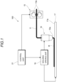
- FIG. 1 is a schematic configuration diagram showing an additive manufacturing apparatus 100 using FDM.
- the additive manufacturing apparatus 100 includes a filament feeding unit 13 that feeds a fiber-reinforced resin filament (hereinafter, also referred to as a filament) 11, a head unit 15, a table 17, a molding driving unit 19, and a control unit 21.
- a filament feeding unit 13 that feeds a fiber-reinforced resin filament (hereinafter, also referred to as a filament) 11, a head unit 15, a table 17, a molding driving unit 19, and a control unit 21.
- the filament feeding unit 13 includes a pair of driving rollers 13a that sandwich the filament 11, and a driving unit (not shown) such as a motor that rotationally drives at least one of the driving rollers 13a.
- the head unit 15 includes a heating unit (not shown) that thermally melts the fed filament 11, and a nozzle 15a that ejects a manufacturing material melted by the heating unit.
- a cutting unit such as a cutter or a laser cutting device that cuts reinforcing fibers included in the filament 11 may be provided.
- the table 17 is disposed to face the nozzle 15a of the head unit 15, and has a manufacturing surface 17a on which a manufactured object is laminated.
- the molding driving unit 19 relatively moves the head unit 15 and the table 17 to form a manufacturing material ejected from the nozzle 15a of the head unit 15 along a desired path.
- the molding driving unit 19 may include a biaxial driving mechanism that moves the head unit 15 within a plane of the manufacturing surface 17a of the table 17, and a raising and lowering mechanism that adjusts a laminating height by raising and lowering the table 17.
- the control unit 21 has a function of controlling the feeding of the filament 11 by the filament feeding unit 13 and the relative movement of the head unit 15 by the molding driving unit 19, and a function of collectively controlling other units.
- the control unit 21 receives a program for controlling units including the filament feeding unit 13 and the molding driving unit 19, and executes the program to additively manufacture a manufactured object having a desired shape.
- the control unit 21 feeds the filament 11 to the head unit 15, and the fed filament 11 is thermally melted by the head unit 15. Then, a manufacturing step of ejecting the manufacturing material obtained by melting the filament 11 from the nozzle 15a of the head unit 15 while moving the head unit 15 and the table 17 relative to each other is performed. Accordingly, a manufactured object having a desired shape is formed on the table 17.
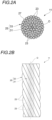
- FIG. 2A is a cross-sectional view in a radial direction perpendicular to an axial direction of the filament 11.
- FIG. 2B is a side view of the filament 11.
- the filament 11 is a linear resin material used as a manufacturing raw material for a 3D printer such as the additive manufacturing apparatus 100 described above, and a fiber bundle 25 including continuous reinforcing fibers 23 is impregnated with a matrix resin (hereinafter, also simply referred to as a resin) 27 including a thermoplastic resin.
- a matrix resin hereinafter, also simply referred to as a resin
- the matrix resin 27 is not limited to the thermoplastic resin, and may be, for example, another resin material such as a thermosetting resin.
- the filament 11 includes a first group of fiber bundles 31 and a second group of fiber bundles 33 as the fiber bundle 25.
- the first group of fiber bundles 31 is disposed along a filament central axis O
- the second group of fiber bundles 33 is disposed around the first group of fiber bundles 31.
- the second group of fiber bundles 33 is disposed at a radially outer side of the first group of fiber bundles 31, and is applied with twisting around the first group of fiber bundles 31.
- the first group of fiber bundles 31 disposed along the filament central axis O is arranged parallel to the filament central axis O.
- the reinforcing fibers 23 constituting the first group of fiber bundles 31 are aligned in such a way that an orientation direction of the reinforcing fibers 23 is parallel to the filament central axis O.
- twisting around the filament central axis O may be applied to the first group of fiber bundles 31.
- a twisting angle of the first group of fiber bundles 31 is set smaller than a twisting angle of the second group of fiber bundles 33.
- organic fibers such as a polyethylene fiber, an aramid fiber, and a Xyron fiber
- inorganic fibers such as a boron fiber, a glass fiber, a carbon fiber, a metal fiber, and a rock fiber
- a fiber that has been subjected to a surface treatment may be used in order to improve adhesion strength between the resin and the fiber.
- thermoplastic resins may be used alone, and a thermoplastic resin in which a plurality of these resins is blended may be used to improve heat resistance, heat distortion temperature, heat aging resistance, tensile properties, bending properties, creep properties, compression properties, fatigue properties, impact properties, and sliding properties of the thermoplastic resin.
- thermoplastic resin include polyetheretherketone resin (PEEK)/polytetrafluoroethylene (PTFE) and PEEK/polybenzimidazole (PBI).
- PEEK polyetheretherketone resin
- PTFE polytetrafluoroethylene
- PBI polybenzimidazole
- the thermoplastic resin may be obtained by adding short fibers such as a carbon fiber and a glass fiber, talc, or the like to a resin.
- thermoplastic resin By adding phenolic antioxidants, thioether-based antioxidants, or phosphite-based antioxidants, benzotriazole-based ultraviolet absorbers or triazine-based ultraviolet absorbers, hydrazide-based metal deactivating agents or amide-based metal deactivating agents, or the like to the thermoplastic resin, durability of the manufactured object may be improved.
- the flame retardancy of the manufactured object may be improved.
- thermoplastic resin By adding a phosphate ester metal salt-based core material or sorbitol-based core material to the thermoplastic resin, the thermal expansion during the manufacturing may be controlled, and the manufacturing accuracy may be improved.
- thermoplastic resin By adding a non-ionic-based permanent antistatic agent, anionic-based permanent antistatic agent, and cationic-based permanent antistatic agent to the thermoplastic resin, the antistatic property of the manufactured object can be improved.
- the filament can be smoothly fed during the manufacturing.
- the filament 11 having the present configuration has the first group of fiber bundles 31 and the second group of fiber bundles 33, as the fiber bundle 25 including the continuous reinforcing fibers 23, and the twisting angle of the first group of fiber bundles 31 is set smaller than the twisting angle of the second group of fiber bundles 33. Accordingly, the tensile strength and the bending rigidity are improved by the first group of fiber bundles 31 while the good flexibility is achieved due to the second group of fiber bundles 33.
- the second group of fiber bundles 33 is twisted at a twisting angle larger than that of the first group of fiber bundles 31, and thus the flexibility of the second group of fiber bundles 33 is improved. Therefore, when printing a curvature unit, the filament 11 easily follows a curvature, and manufacturing accuracy is improved.
- the fiber bundle 25 smoothly spreads when being ejected from the nozzle, and the reinforcing fibers 23 are uniformly distributed during the manufacturing, and thus the fibers are well fused to the table or the base. Furthermore, since the fiber bundle 25 easily spreads, a gap is less likely to occur between the adjacent filaments 11 in a plan view, and the filaments are easily gathered.
- a synergistic effect of the first group of fiber bundles 31 and the second group of fiber bundles 33 described above makes it easy to obtain a high-strength manufactured object with reduced variation in strength.
- FIG. 3A is a cross-sectional view in a radial direction of a filament 11A according to Modification 1.
- FIG. 3B is a side view of the filament 11A according to Modification 1.
- the first group of fiber bundles 31 disposed along the filament central axis O is also arranged parallel to the filament central axis O.
- the twisting around the first group of fiber bundles 31 is applied to the second group of fiber bundles 33 disposed at the radially outer side of the first group of fiber bundles 31.
- the reinforcing fibers 23 constituting the first group of fiber bundles 31 are aligned in such a way that the orientation direction of the reinforcing fibers 23 is parallel to the filament central axis O.
- an outer circumference (radially outer side) of the second group of fiber bundles 33 is covered with a resin 35.
- the resin 35 is preferably the same material as the matrix resin 27 described above. Regions of the first group of fiber bundles 31 and the second group of fiber bundles 33 may be impregnated with the resin 35 or may be impregnated with the matrix resin 27 described above. In the present configuration, the twisting around the filament central axis O may also be applied to the first group of fiber bundles 31. In this case, the twisting angle of the first group of fiber bundles 31 is set smaller than the twisting angle of the second group of fiber bundles 33.
- the filament 11A since the outer circumference of the second group of fiber bundles 33 is covered with the resin 35, the tensile strength and the bending rigidity are improved by the first group of fiber bundles 31 while the good flexibility is achieved.
- the reinforcing fibers 23 of the second group of fiber bundles 33 provided on the outer side of the first group of fiber bundles 31 can be protected by the resin 35.
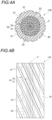
- FIG. 4A is a cross-sectional view in a radial direction of a filament 11B according to Modification 2.
- FIG. 4B is a side view of the filament 11B according to Modification 2.
- the outer circumference (radially outer side) of the second group of fiber bundles 33 is also covered with the resin 35.
- grooves 37 are formed on an outer circumferential surface of the filament 11B.
- the plurality of grooves 37 are formed at equal intervals in a circumferential direction of the filament 11B, and are formed in a spiral shape along an axial direction of the filament.
- the groove 37 described above may be replaced with a ridge formed on the outer circumferential surface of the filament 11B and protruding toward the radially outer side.
- the grooves 37 or the ridges can increase a surface area of the outer circumferential surface and improve the flexibility.
- the grooves 37 or the ridges described above are not limited to a spiral shape, and may be linear along the axial direction of the filament 11B.
- a configuration may be employed in which a plurality of annular grooves or annular protrusions formed continuously in the circumferential direction of the filament 11B are provided along the axial direction of the filament 11B.
- the grooves or the ridges described above may be disposed in combination. That is, at least spiral or linear irregularities along the axial direction of the filament, or a plurality of annular irregularities disposed along the axial direction of the filament are formed on the outer circumferential surface of the filament 11B.
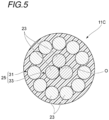
- FIG. 5 is a cross-sectional view in a radial direction of a filament 11C according to Modification 3.
- the first group of fiber bundles 31 and the second group of fiber bundles 33 are disposed in the opposite order to that in the filament 11 in a cross-sectional view. That is, the second group of fiber bundles 33 is disposed along the filament central axis O, and the first group of fiber bundles 31 is disposed around the second group of fiber bundles 33.
- the twisting with respect to the filament central axis O is applied to the second group of fiber bundles 33 disposed along the filament central axis O, and the first group of fiber bundles 31 disposed around the second group of fiber bundles 33 is arranged parallel to the filament central axis O.
- the reinforcing fibers 23 constituting the first group of fiber bundles 31 are aligned in such a way that the orientation direction of the reinforcing fibers 23 is parallel to the filament central axis O.
- the twisting is applied to the second group of fiber bundles 33 disposed at a radially inner side of the first group of fiber bundles 31.
- the tensile strength and the bending rigidity are also improved by the first group of fiber bundles 31 while the good flexibility is achieved.
- the twisting around the filament central axis O may also be applied to the first group of fiber bundles 31.
- the twisting angle of the first group of fiber bundles 31 is set smaller than the twisting angle of the second group of fiber bundles 33.
- a filament manufacturing apparatus shown here is an example, and is not limited thereto.
- FIG. 6 is a schematic configuration diagram of a filament manufacturing apparatus 200.
- the filament manufacturing apparatus 200 includes a plurality of fiber material supply units 51 that feed the fiber bundles 25 each wound in a coil shape at a predetermined speed, a kneading extruder 65 that kneads and melts a resin, and a resin bath unit 67 that impregnates the fiber bundle 25 fed from the fiber material supply units 51 with the resin plasticized by the kneading extruder 65.
- the filament manufacturing apparatus 200 includes a cooling unit 71 disposed at a downstream side of the resin bath unit 67, and a twisting unit 81 disposed at a downstream side of the cooling unit 71.
- a composite (impregnated fiber material) 41 in which the fiber bundle 25 is impregnated with the resin is fed from the resin bath unit 67.
- the cooling unit 71 cools the composite 41 fed from the resin bath unit 67.
- the twisting unit 81 mainly applies the twisting around an axial center to the fiber bundle 25 before cooling.
- the kneading extruder 65 is rotatably provided with a screw shaft (not shown) including a kneading blade in a chamber 66 having a cavity therein, and melts and plasticizes the resin fed from a hopper 63.
- the resin bath unit 67 is formed in a cylindrical shape with a cylinder axial direction extending up and down, and the resin 35 plasticized by the kneading extruder 65 is supplied and stored inside the cylinder. An upper end portion of the resin bath unit 67 is opened, and the fiber bundle 25 guided by a guide roller 53 is drawn into the resin stored in the resin bath unit 67 from the upper end opening.
- a plurality of impregnation rolls (not shown) which are rotatably held with axes thereof oriented in a horizontal direction are provided inside the resin bath unit 67.
- the fiber bundle 25 introduced from the upper end opening of the resin bath unit 67 is sequentially laid over the impregnation rolls and sent to an outlet portion 68.
- the outlet portion 68 at a lower end portion of the resin bath unit 67 is provided with a die 69 for shaping an outer circumference of the composite 41 of the resin and the fiber bundle 25 when the composite 41 is drawn out to the outside.
- a die 69 for shaping an outer circumference of the composite 41 of the resin and the fiber bundle 25 when the composite 41 is drawn out to the outside.
- irregularities such as the grooves 37 and the ridges on the outer circumferential surface of the filament.
- the filament 11 can be manufactured in which the fiber bundle 25 is impregnated with the matrix resin containing the thermoplastic resin, the first group of fiber bundles 31 is provided along the filament central axis O, and the second group of fiber bundles 33 to which the twisting is applied is provided on the outer circumference of the first group of fiber bundles 31.
- the twisting may be applied to both the first group of fiber bundles 31 and the second group of fiber bundles 33, and in this case, the twisting angle of the first group of fiber bundles 31 is set smaller than the twisting angle of the second group of fiber bundles 33.
- the second group of fiber bundles is twisted at the twisting angle larger than that of the first group of fiber bundles, and thus the flexibility of the second group of fiber bundles is improved. Therefore, when printing a curvature unit, the filament easily follows a curvature, and manufacturing accuracy is improved.
- the first group of fiber bundles has good fiber fusion because the fiber bundle smoothly spreads and is uniformly distributed during the manufacturing. Furthermore, since the fiber bundle easily spreads, a gap is less likely to be generated between the adjacent filaments in a plan view, and the filaments are easily gathered. Accordingly, a manufactured object having excellent strength properties is obtained.
Landscapes
- Chemical & Material Sciences (AREA)
- Engineering & Computer Science (AREA)
- Materials Engineering (AREA)
- Manufacturing & Machinery (AREA)
- Physics & Mathematics (AREA)
- Mechanical Engineering (AREA)
- Optics & Photonics (AREA)
- Ceramic Engineering (AREA)
- Civil Engineering (AREA)
- Composite Materials (AREA)
- Structural Engineering (AREA)
- Moulding By Coating Moulds (AREA)
Abstract
Description
- The present invention relates to a filament and a manufactured object manufacturing method.
- In order to improve the mechanical strength of a manufactured object, a use of manufacturing fiber reinforced plastics (FRP) with a fused deposition modeling (FDM) 3D printer using a continuous fiber reinforced resin strand has been expanded. Such a 3D printer is used in a manufacturing step for jigs and parts, such as bicycle frames.
-
Patent Literature 1 discloses a filament (strand) used in a fused deposition modeling 3D printer, including a base material containing a thermoplastic resin as a main component; and at least one fiber or fiber bundle impregnated in the base material and extending in an axial direction, in which twisting is applied to the fiber or the fiber bundle along the axial direction. - Patent Literature 1:
JP2021-123026A - A
filament 5 shown inFIG. 7A and FIG. 7B has afiber bundle 3 in which twisting is applied to a plurality offibers 1 in an orientation angle inclined along an axial direction. According to thefilament 5, good flexibility of thefilament 5 can be obtained when a manufactured object is manufactured by the fused deposition modeling. However, in the case of thefilament 5, the twisting is applied to theentire fiber bundle 3, and thus tensile strength and bending rigidity in the axial direction may be reduced. - When the manufactured object is manufactured by the fused deposition modeling, a thermoplastic resin of the
filament 5 is melted from a head unit having a heating mechanism, and thefiber bundle 3 and the melted resin are ejected from a nozzle attached to the head unit, and are laminated on a table or a base layer including a printing path that has already been ejected. In this case, if theentire fiber bundle 3 of thefilament 5 is twisted, thefiber bundle 3 ejected from the nozzle is difficult to spread, thefibers 1 are insufficiently fused to the table or the base, and thefibers 1 are likely to be unevenly distributed during manufacturing. Therefore, strength of the manufactured object manufactured may be reduced or varied. - Accordingly, an object of the present invention is to provide a filament having good flexibility, high tensile strength, and high bending rigidity, and to provide a manufactured object manufacturing method which can manufacture a manufactured object having excellent strength properties by using the filament.
- The present invention includes the following configurations.
- (1) A filament used as a manufacturing raw material for a 3D printer, in which
- a fiber bundle including a continuous reinforcing fiber is impregnated with a matrix resin,
- the filament includes a first group of fiber bundles and a second group of fiber bundles, and
- a twisting angle of the first group of fiber bundles is smaller than a twisting angle of the second group of fiber bundles.
- (2) A manufactured object manufacturing method, including:
thermally melting the filament according to (1) and ejecting a thermally melted manufacturing material to additively manufacture a manufactured object. - According to the present invention, a filament having good flexibility, high tensile strength, and high bending rigidity can be obtained. By manufacturing a manufactured object using the filament, the manufactured object having excellent strength properties can be obtained.
-
- [
FIG. 1] FIG. 1 is a schematic configuration diagram showing an additive manufacturing apparatus using FDM. - [
FIG. 2A] FIG. 2A is a cross-sectional view in a radial direction perpendicular to an axial direction of the filament. - [
FIG. 2B] FIG. 2B is a side view of the filament. - [
FIG. 3A] FIG. 3A is a cross-sectional view in a radial direction of a filament according toModification 1. - [
FIG. 3B] FIG. 3B is a side view of the filament according toModification 1. - [
FIG. 4A] FIG. 4A is a cross-sectional view in a radial direction of a filament according to Modification 2. - [
FIG. 4B] FIG. 4B is a side view of the filament according to Modification 2. - [
FIG. 5] FIG. 5 is a cross-sectional view in a radial direction of a filament according toModification 3. - [
FIG. 6] FIG. 6 is a schematic perspective view of a filament manufacturing apparatus. - [
FIG. 7A] FIG. 7A is a cross-sectional view in a radial direction of a filament in the related art. - [
FIG. 7B] FIG. 7B is a side view of the filament in the related art. - Hereinafter, embodiments according to the present invention will be described in detail with reference to the drawings.
- First, a configuration of a 3D printer will be briefly described. An additive manufacturing apparatus shown here is an example of the 3D printer, and may be another configuration.
-
FIG. 1 is a schematic configuration diagram showing anadditive manufacturing apparatus 100 using FDM. - The
additive manufacturing apparatus 100 includes afilament feeding unit 13 that feeds a fiber-reinforced resin filament (hereinafter, also referred to as a filament) 11, ahead unit 15, a table 17, amolding driving unit 19, and acontrol unit 21. - The
filament feeding unit 13 includes a pair ofdriving rollers 13a that sandwich thefilament 11, and a driving unit (not shown) such as a motor that rotationally drives at least one of thedriving rollers 13a. - The
head unit 15 includes a heating unit (not shown) that thermally melts the fedfilament 11, and anozzle 15a that ejects a manufacturing material melted by the heating unit. Although not shown, a cutting unit such as a cutter or a laser cutting device that cuts reinforcing fibers included in thefilament 11 may be provided. - The table 17 is disposed to face the
nozzle 15a of thehead unit 15, and has amanufacturing surface 17a on which a manufactured object is laminated. - The
molding driving unit 19 relatively moves thehead unit 15 and the table 17 to form a manufacturing material ejected from thenozzle 15a of thehead unit 15 along a desired path. For example, themolding driving unit 19 may include a biaxial driving mechanism that moves thehead unit 15 within a plane of themanufacturing surface 17a of the table 17, and a raising and lowering mechanism that adjusts a laminating height by raising and lowering the table 17. - The
control unit 21 has a function of controlling the feeding of thefilament 11 by thefilament feeding unit 13 and the relative movement of thehead unit 15 by themolding driving unit 19, and a function of collectively controlling other units. Thecontrol unit 21 receives a program for controlling units including thefilament feeding unit 13 and themolding driving unit 19, and executes the program to additively manufacture a manufactured object having a desired shape. - In the
additive manufacturing apparatus 100 having the present configuration, thecontrol unit 21 feeds thefilament 11 to thehead unit 15, and the fedfilament 11 is thermally melted by thehead unit 15. Then, a manufacturing step of ejecting the manufacturing material obtained by melting thefilament 11 from thenozzle 15a of thehead unit 15 while moving thehead unit 15 and the table 17 relative to each other is performed. Accordingly, a manufactured object having a desired shape is formed on the table 17. - Next, a configuration of the
filament 11 will be described. -
FIG. 2A is a cross-sectional view in a radial direction perpendicular to an axial direction of thefilament 11.FIG. 2B is a side view of thefilament 11. - As shown in
FIG. 2A and FIG. 2B , thefilament 11 is a linear resin material used as a manufacturing raw material for a 3D printer such as theadditive manufacturing apparatus 100 described above, and afiber bundle 25 including continuous reinforcingfibers 23 is impregnated with a matrix resin (hereinafter, also simply referred to as a resin) 27 including a thermoplastic resin. Note that thematrix resin 27 is not limited to the thermoplastic resin, and may be, for example, another resin material such as a thermosetting resin. - The
filament 11 includes a first group offiber bundles 31 and a second group offiber bundles 33 as thefiber bundle 25. The first group offiber bundles 31 is disposed along a filament central axis O, and the second group offiber bundles 33 is disposed around the first group of fiber bundles 31. The second group offiber bundles 33 is disposed at a radially outer side of the first group offiber bundles 31, and is applied with twisting around the first group of fiber bundles 31. The first group offiber bundles 31 disposed along the filament central axis O is arranged parallel to the filament central axis O. The reinforcingfibers 23 constituting the first group offiber bundles 31 are aligned in such a way that an orientation direction of the reinforcingfibers 23 is parallel to the filament central axis O. - Note that twisting around the filament central axis O may be applied to the first group of fiber bundles 31. In this case, a twisting angle of the first group of
fiber bundles 31 is set smaller than a twisting angle of the second group of fiber bundles 33. - As the reinforcing
fibers 23 of thefiber bundle 25 constituting thefilament 11, organic fibers such as a polyethylene fiber, an aramid fiber, and a Xyron fiber, and inorganic fibers such as a boron fiber, a glass fiber, a carbon fiber, a metal fiber, and a rock fiber may be used. As the reinforcing fiber, a fiber that has been subjected to a surface treatment may be used in order to improve adhesion strength between the resin and the fiber. - As the thermoplastic resin which is a main component of the
matrix resin 27 of thefilament 11, polyolefin-based resins such as polypropylene or polyethylene, acrylonitrile-butadiene-styrene resins, polystyrene resins, polyester-based resins such as polyethylene terephthalate, polybutylene terephthalate, or polylactic acid, polyamide-based resins, aromatic polyamide-based resins, polyetherimide, polyarylimide, polyarylate, polyether ether ketone, polyaryletherketone, polybenzimidazole, polyethersulfone, polysulfone, polyvinylidene fluoride resins, liquid crystal polymers, polycarbonate resins, polyacetal, polyphenylene sulfide and the like may be used. - These thermoplastic resins may be used alone, and a thermoplastic resin in which a plurality of these resins is blended may be used to improve heat resistance, heat distortion temperature, heat aging resistance, tensile properties, bending properties, creep properties, compression properties, fatigue properties, impact properties, and sliding properties of the thermoplastic resin. Examples of the thermoplastic resin include polyetheretherketone resin (PEEK)/polytetrafluoroethylene (PTFE) and PEEK/polybenzimidazole (PBI). The thermoplastic resin may be obtained by adding short fibers such as a carbon fiber and a glass fiber, talc, or the like to a resin.
- By adding phenolic antioxidants, thioether-based antioxidants, or phosphite-based antioxidants, benzotriazole-based ultraviolet absorbers or triazine-based ultraviolet absorbers, hydrazide-based metal deactivating agents or amide-based metal deactivating agents, or the like to the thermoplastic resin, durability of the manufactured object may be improved.
- By adding a phthalic acid-based plasticizer or polyester-based plasticizer to the thermoplastic resin, the flexibility may be improved, and the manufacturing accuracy during manufacturing and the flexibility of the manufactured object may be improved.
- By adding a halogen-based flame retardant, phosphate ester-based flame retardant, inorganic flame retardant, or intumescent flame retardant to the thermoplastic resin, the flame retardancy of the manufactured object may be improved.
- By adding a phosphate ester metal salt-based core material or sorbitol-based core material to the thermoplastic resin, the thermal expansion during the manufacturing may be controlled, and the manufacturing accuracy may be improved.
- By adding a non-ionic-based permanent antistatic agent, anionic-based permanent antistatic agent, and cationic-based permanent antistatic agent to the thermoplastic resin, the antistatic property of the manufactured object can be improved.
- By adding a hydrocarbon-based lubricant or metal soap-based lubricant to the thermoplastic resin to improve the slidability of the continuous fiber-reinforced filament, the filament can be smoothly fed during the manufacturing.
- In the filament used for a 3D printer, the flexibility can be improved by applying the twisting to the fiber bundle, but since an orientation angle of the reinforcing fibers of the fiber bundle is inclined with respect to the axial direction, there is a risk of a decrease in the tensile strength and the bending rigidity in the axial direction. If the entire fiber bundle is twisted, the fiber bundle ejected from the nozzle is difficult to spread when manufacturing a manufactured object by the fused deposition modeling. Therefore, the fusing to a base or the table 17 shown in
FIG. 1 may be insufficient, and the reinforcing fibers may be unevenly distributed during the manufacturing. The fiber bundle is difficult to spread, so that a gap is likely to occur between adjacent filaments when viewed in a plan view. Therefore, strength of the manufactured object manufactured may be reduced or varied. - Accordingly, the
filament 11 having the present configuration has the first group offiber bundles 31 and the second group offiber bundles 33, as thefiber bundle 25 including the continuous reinforcingfibers 23, and the twisting angle of the first group offiber bundles 31 is set smaller than the twisting angle of the second group of fiber bundles 33. Accordingly, the tensile strength and the bending rigidity are improved by the first group offiber bundles 31 while the good flexibility is achieved due to the second group of fiber bundles 33. - When the manufactured object is manufactured using the
filament 11, the second group offiber bundles 33 is twisted at a twisting angle larger than that of the first group offiber bundles 31, and thus the flexibility of the second group offiber bundles 33 is improved. Therefore, when printing a curvature unit, thefilament 11 easily follows a curvature, and manufacturing accuracy is improved. - In the first group of
fiber bundles 31, thefiber bundle 25 smoothly spreads when being ejected from the nozzle, and the reinforcingfibers 23 are uniformly distributed during the manufacturing, and thus the fibers are well fused to the table or the base. Furthermore, since thefiber bundle 25 easily spreads, a gap is less likely to occur between theadjacent filaments 11 in a plan view, and the filaments are easily gathered. - A synergistic effect of the first group of
fiber bundles 31 and the second group offiber bundles 33 described above makes it easy to obtain a high-strength manufactured object with reduced variation in strength. - In particular, when the orientation direction of the reinforcing
fibers 23 of the first group offiber bundles 31 is aligned parallel to the axial direction of the filament, an increase in the tensile strength and the bending rigidity due to the first group offiber bundles 31 becomes significant. - Next, modifications of the
filament 11 described above will be described. -
FIG. 3A is a cross-sectional view in a radial direction of afilament 11A according toModification 1.FIG. 3B is a side view of thefilament 11A according toModification 1. - As shown in
FIG. 3A and FIG. 3B , in thefilament 11A according toModification 1, the first group offiber bundles 31 disposed along the filament central axis O is also arranged parallel to the filament central axis O. The twisting around the first group offiber bundles 31 is applied to the second group offiber bundles 33 disposed at the radially outer side of the first group of fiber bundles 31. The reinforcingfibers 23 constituting the first group offiber bundles 31 are aligned in such a way that the orientation direction of the reinforcingfibers 23 is parallel to the filament central axis O. In thefilament 11A according toModification 1, an outer circumference (radially outer side) of the second group offiber bundles 33 is covered with aresin 35. Theresin 35 is preferably the same material as thematrix resin 27 described above. Regions of the first group offiber bundles 31 and the second group offiber bundles 33 may be impregnated with theresin 35 or may be impregnated with thematrix resin 27 described above. In the present configuration, the twisting around the filament central axis O may also be applied to the first group of fiber bundles 31. In this case, the twisting angle of the first group offiber bundles 31 is set smaller than the twisting angle of the second group of fiber bundles 33. - According to the
filament 11A, since the outer circumference of the second group offiber bundles 33 is covered with theresin 35, the tensile strength and the bending rigidity are improved by the first group offiber bundles 31 while the good flexibility is achieved. The reinforcingfibers 23 of the second group offiber bundles 33 provided on the outer side of the first group offiber bundles 31 can be protected by theresin 35. -
FIG. 4A is a cross-sectional view in a radial direction of afilament 11B according to Modification 2.FIG. 4B is a side view of thefilament 11B according to Modification 2. - As shown in
FIG. 4A and FIG. 4B , in a case of thefilament 11B according to Modification 2, similar to thefilament 11A according toModification 1, the outer circumference (radially outer side) of the second group offiber bundles 33 is also covered with theresin 35. Furthermore,grooves 37 are formed on an outer circumferential surface of thefilament 11B. The plurality ofgrooves 37 are formed at equal intervals in a circumferential direction of thefilament 11B, and are formed in a spiral shape along an axial direction of the filament. Thegroove 37 described above may be replaced with a ridge formed on the outer circumferential surface of thefilament 11B and protruding toward the radially outer side. - According to the
filament 11B according to Modification 2, thegrooves 37 or the ridges can increase a surface area of the outer circumferential surface and improve the flexibility. Thegrooves 37 or the ridges described above are not limited to a spiral shape, and may be linear along the axial direction of thefilament 11B. A configuration may be employed in which a plurality of annular grooves or annular protrusions formed continuously in the circumferential direction of thefilament 11B are provided along the axial direction of thefilament 11B. The grooves or the ridges described above may be disposed in combination. That is, at least spiral or linear irregularities along the axial direction of the filament, or a plurality of annular irregularities disposed along the axial direction of the filament are formed on the outer circumferential surface of thefilament 11B. -
FIG. 5 is a cross-sectional view in a radial direction of afilament 11C according toModification 3. - As shown in
FIG. 5 , in thefilament 11C according toModification 3, the first group offiber bundles 31 and the second group offiber bundles 33 are disposed in the opposite order to that in thefilament 11 in a cross-sectional view. That is, the second group offiber bundles 33 is disposed along the filament central axis O, and the first group offiber bundles 31 is disposed around the second group of fiber bundles 33. - The twisting with respect to the filament central axis O is applied to the second group of
fiber bundles 33 disposed along the filament central axis O, and the first group offiber bundles 31 disposed around the second group offiber bundles 33 is arranged parallel to the filament central axis O. The reinforcingfibers 23 constituting the first group offiber bundles 31 are aligned in such a way that the orientation direction of the reinforcingfibers 23 is parallel to the filament central axis O. - According to the
filament 11C, the twisting is applied to the second group offiber bundles 33 disposed at a radially inner side of the first group of fiber bundles 31. According to the present configuration, the tensile strength and the bending rigidity are also improved by the first group offiber bundles 31 while the good flexibility is achieved. - Note that in
Modification 3, the twisting around the filament central axis O may also be applied to the first group of fiber bundles 31. In this case, the twisting angle of the first group offiber bundles 31 is set smaller than the twisting angle of the second group of fiber bundles 33. - Next, a method for manufacturing the filament described above will be described. A filament manufacturing apparatus shown here is an example, and is not limited thereto.
-
FIG. 6 is a schematic configuration diagram of afilament manufacturing apparatus 200. - The
filament manufacturing apparatus 200 includes a plurality of fibermaterial supply units 51 that feed the fiber bundles 25 each wound in a coil shape at a predetermined speed, a kneadingextruder 65 that kneads and melts a resin, and aresin bath unit 67 that impregnates thefiber bundle 25 fed from the fibermaterial supply units 51 with the resin plasticized by the kneadingextruder 65. - The
filament manufacturing apparatus 200 includes acooling unit 71 disposed at a downstream side of theresin bath unit 67, and a twistingunit 81 disposed at a downstream side of the coolingunit 71. A composite (impregnated fiber material) 41 in which thefiber bundle 25 is impregnated with the resin is fed from theresin bath unit 67. The coolingunit 71 cools the composite 41 fed from theresin bath unit 67. The twistingunit 81 mainly applies the twisting around an axial center to thefiber bundle 25 before cooling. - The kneading
extruder 65 is rotatably provided with a screw shaft (not shown) including a kneading blade in achamber 66 having a cavity therein, and melts and plasticizes the resin fed from ahopper 63. - The
resin bath unit 67 is formed in a cylindrical shape with a cylinder axial direction extending up and down, and theresin 35 plasticized by the kneadingextruder 65 is supplied and stored inside the cylinder. An upper end portion of theresin bath unit 67 is opened, and thefiber bundle 25 guided by aguide roller 53 is drawn into the resin stored in theresin bath unit 67 from the upper end opening. - A plurality of impregnation rolls (not shown) which are rotatably held with axes thereof oriented in a horizontal direction are provided inside the
resin bath unit 67. Thefiber bundle 25 introduced from the upper end opening of theresin bath unit 67 is sequentially laid over the impregnation rolls and sent to anoutlet portion 68. - The
outlet portion 68 at a lower end portion of theresin bath unit 67 is provided with adie 69 for shaping an outer circumference of the composite 41 of the resin and thefiber bundle 25 when the composite 41 is drawn out to the outside. Depending on an opening shape of the die 69, it is possible to form irregularities such as thegrooves 37 and the ridges on the outer circumferential surface of the filament. - The cooling
unit 71 is a water tank elongated in a direction in which the composite 41 is drawn out from theresin bath unit 67, and coolingwater 72 is stored in the tank. In thecooling unit 71, the resin impregnated in thefiber bundle 25 in the composite 41 is cooled and hardened in the coolingwater 72. - The twisting
unit 81 shown here is disposed at the downstream side of the coolingunit 71 and has a pair of upper take-up roll 83 and lower take-up roll 85 with outer circumferential surfaces thereof brought into contact with each other. Such a twistingunit 81 can employ various mechanisms. For example, although not shown, various mechanisms such as a mechanism that rotates a bobbin for winding thefilament 11 around an axis of thefilament 11 can be employed. - The take-up
roller 83 and the take-uproller 85 have a function of drawing thefiber bundle 25 from the fibermaterial supply units 51 to theresin bath unit 67, and further drawing out the composite 41 from theresin bath unit 67 to thecooling unit 71 and the twistingunit 81. A winding unit (not shown) is separately provided at a downstream side of the twistingunit 81 to wind the obtainedfilament 11 on a bobbin or the like. - A manufacturing procedure of the
filament 11 using thefilament manufacturing apparatus 200 described above is as follows. - An impregnation step is performed by the
resin bath unit 67 of thefilament manufacturing apparatus 200. Specifically, the resin supplied from thehopper 63 is kneaded in the kneadingextruder 65, and the resin in a molten state is stored in theresin bath unit 67. Thefiber bundle 25 is supplied to theresin bath unit 67 from the fibermaterial supply units 51. In theresin bath unit 67, thefiber bundle 25 is impregnated with the resin in the molten state, and passes through the die 69 disposed at theoutlet portion 68 to adjust an amount of impregnation. The impregnation results in a state in which the matrix resin is present in the gap within eachfiber bundle 25, present around eachfiber bundle 25, and present between the fiber bundles 25. The composite 41 of the matrix resin and thefiber bundle 25 obtained in this way is cooled in thecooling unit 71. - In a twisting step, the twisting is applied to the
fiber bundle 25 impregnated with the resin in theresin bath unit 67 by the twistingunit 81. Specifically, the composite 41 that passes through the coolingunit 71 passes through nips of the take-up roll 83 and the take-up roll 85 of the twistingunit 81 while these rolls rotate. Accordingly, the twisting is applied to thefiber bundle 25. In the present example, the twisting is applied to the second group offiber bundles 33 on the outer circumference side of the first group offiber bundles 31 along the filament central axis O. The number of times of twisting and the twisting angle can be adjusted by adjusting an inclination angle with respect to a take-up direction of the take-up roll 83 and the take-up roll 85 described above. The closer to the filament central axis O, the smaller the twisting angle can be. - In this way, the
filament 11 can be manufactured in which thefiber bundle 25 is impregnated with the matrix resin containing the thermoplastic resin, the first group offiber bundles 31 is provided along the filament central axis O, and the second group offiber bundles 33 to which the twisting is applied is provided on the outer circumference of the first group of fiber bundles 31. When manufacturing thefilament 11, the twisting may be applied to both the first group offiber bundles 31 and the second group offiber bundles 33, and in this case, the twisting angle of the first group offiber bundles 31 is set smaller than the twisting angle of the second group of fiber bundles 33. - The present disclosure is not limited to the embodiments described above, and combinations of the respective configurations of the embodiments and changes and applications made by those skilled in the art based on the description of the specification and well-known techniques are also intended for the present disclosure and are included in the scope of protection.
- As described above, the present specification discloses the following matters.
- (1) A filament used as a manufacturing raw material for a 3D printer, in which
- a fiber bundle including a continuous reinforcing fiber is impregnated with a matrix resin,
- the filament includes a first group of fiber bundles and a second group of fiber bundles, and
- a twisting angle of the first group of fiber bundles is smaller than a twisting angle of the second group of fiber bundles.
- According to the filament, the fiber bundle including the continuous reinforcing fiber includes the first group of fiber bundles and the second group of fiber bundles, and the twisting angle of the first group of fiber bundles is smaller than the twisting angle of the second group of fiber bundles. Accordingly, tensile strength and bending rigidity can be improved by the first group of fiber bundles while good flexibility is achieved.
- (2) The filament according to (1), in which
- the first group of fiber bundles is disposed along a filament central axis, and
- the second group of fiber bundles is disposed at a radially outer side of the first group of fiber bundles, and is applied with twisting around the first group of fiber bundles.
- According to the filament, the second group of fiber bundles is disposed at the radially outer side of the first group of fiber bundles disposed along the filament central axis, and is applied with the twisting around the first group of fiber bundles. Accordingly, the tensile strength and the bending rigidity can be improved in a well-balanced manner in a radial direction while the good flexibility is achieved.
- (3) The filament according to (1) or (2), in which
- an orientation direction of the reinforcing fiber of the first group of fiber bundles is aligned parallel to an axial direction of the filament.
- According to the filament, the tensile strength and the bending rigidity can be improved by the first group of fiber bundles while the good flexibility is achieved.
- (4) The filament according to (2), in which
- an outer circumference of the second group of fiber bundles is covered with the matrix resin.
- According to the filament, the outer circumference of the second group of fiber bundles is covered with the matrix resin. Therefore, the tensile strength and the bending rigidity can be improved by the first group of fiber bundles while the good flexibility is achieved, and furthermore, the reinforcing fiber of the second group of fiber bundles provided outside the first group of fiber bundles can be protected by the matrix resin.
- (5) The filament according to (4), in which
- the filament has a spiral groove or ridge on an outer circumferential surface along an axial direction of the filament.
- According to the filament, the spiral groove or ridge is formed on the outer circumferential surface along the axial direction of the filament, and thus a surface area of the outer circumferential surface can be increased, and the flexibility can be improved.
- (6) The filament according to any one of (1) to (5), in which
- the matrix resin is a thermoplastic resin or a thermosetting resin.
- According to the filament, in the filament containing the matrix resin including the thermoplastic resin or the thermosetting resin, the tensile strength and the bending rigidity can be improved by the first group of fiber bundles while the good flexibility is achieved.
- (7) A manufactured object manufacturing method, including:
- thermally melting the filament according to any one of (1) to (6) and ejecting a thermally melted manufacturing material to additively manufacture a manufactured object.
- According to the manufactured object manufacturing method, the second group of fiber bundles is twisted at the twisting angle larger than that of the first group of fiber bundles, and thus the flexibility of the second group of fiber bundles is improved. Therefore, when printing a curvature unit, the filament easily follows a curvature, and manufacturing accuracy is improved. The first group of fiber bundles has good fiber fusion because the fiber bundle smoothly spreads and is uniformly distributed during the manufacturing. Furthermore, since the fiber bundle easily spreads, a gap is less likely to be generated between the adjacent filaments in a plan view, and the filaments are easily gathered. Accordingly, a manufactured object having excellent strength properties is obtained.
- The present application is based on
Japanese Patent Application No. 2022-088614 filed on May 31, 2022 -
- 11, 11A, 11B, 11C: filament
- 13: filament feeding unit
- 15: head unit
- 15a: nozzle
- 17: table
- 19: molding driving unit
- 21: control unit
- 23: reinforcing fiber
- 25: fiber bundle
- 27: matrix resin
- 31: first group of fiber bundles
- 33: second group of fiber bundles
- 35: resin
- 37: groove
- 41: composite
- 100: additive manufacturing apparatus (3D printer)
- 200: filament manufacturing apparatus
Claims (11)
- A filament used as a manufacturing raw material for a 3D printer, whereina fiber bundle including a continuous reinforcing fiber is impregnated with a matrix resin,the filament comprises a first group of fiber bundles and a second group of fiber bundles, anda twisting angle of the first group of fiber bundles is smaller than a twisting angle of the second group of fiber bundles.
- The filament according to claim 1, whereinthe first group of fiber bundles is disposed along a filament central axis, andthe second group of fiber bundles is disposed at a radially outer side of the first group of fiber bundles, and is applied with twisting around the first group of fiber bundles.
- The filament according to claim 1, wherein
an orientation direction of the reinforcing fiber of the first group of fiber bundles is aligned parallel to an axial direction of the filament. - The filament according to claim 2, wherein
an orientation direction of the reinforcing fiber of the first group of fiber bundles is aligned parallel to an axial direction of the filament. - The filament according to claim 2, wherein
an outer circumference of the second group of fiber bundles is covered with the matrix resin. - The filament according to claim 5, wherein
the filament has a spiral groove or ridge on an outer circumferential surface along an axial direction of the filament. - The filament according to any one of claims 1 to 6, wherein
the matrix resin is a thermoplastic resin or a thermosetting resin. - A manufactured object manufacturing method, comprising:
thermally melting the filament according to any one of claims 1 to 6 and ejecting a thermally melted manufacturing material to additively manufacture a manufactured object. - A manufactured object manufacturing method, comprising:
thermally melting the filament according to claim 7 and ejecting a thermally melted manufacturing material to additively manufacture a manufactured object. - The manufactured object manufacturing method according to claim 8, further comprising:
thermally melting the filament and ejecting the thermally melted manufacturing material to additively manufacture the manufactured object. - The manufactured object manufacturing method according to claim 9, further comprising:
thermally melting the filament and ejecting the thermally melted manufacturing material to additively manufacture the manufactured object.
Applications Claiming Priority (2)
| Application Number | Priority Date | Filing Date | Title |
|---|---|---|---|
| JP2022088614A JP7812741B2 (en) | 2022-05-31 | 2022-05-31 | Method for manufacturing filaments and shaped objects |
| PCT/JP2023/016548 WO2023233884A1 (en) | 2022-05-31 | 2023-04-26 | Filament and shaped-object manufacturing method |
Publications (2)
| Publication Number | Publication Date |
|---|---|
| EP4516486A1 true EP4516486A1 (en) | 2025-03-05 |
| EP4516486A4 EP4516486A4 (en) | 2025-09-17 |
Family
ID=89026211
Family Applications (1)
| Application Number | Title | Priority Date | Filing Date |
|---|---|---|---|
| EP23815645.9A Pending EP4516486A4 (en) | 2022-05-31 | 2023-04-26 | FILAMENT AND METHOD FOR MANUFACTURING SHAPED OBJECTS |
Country Status (5)
| Country | Link |
|---|---|
| US (1) | US20250319650A1 (en) |
| EP (1) | EP4516486A4 (en) |
| JP (1) | JP7812741B2 (en) |
| CN (1) | CN119317534A (en) |
| WO (1) | WO2023233884A1 (en) |
Family Cites Families (10)
| Publication number | Priority date | Publication date | Assignee | Title |
|---|---|---|---|---|
| US9074064B2 (en) * | 2010-12-13 | 2015-07-07 | Toray Industries, Inc. | Carbon fiber prepreg, method for producing same and carbon fiber reinforced composite material |
| EP3150361B1 (en) | 2014-05-27 | 2020-12-16 | Nihon University | Three-dimensional printing system and three-dimensional printing method |
| US10513080B2 (en) | 2015-11-06 | 2019-12-24 | United States Of America As Represented By The Administrator Of Nasa | Method for the free form fabrication of articles out of electrically conductive filaments using localized heating |
| JP7307227B2 (en) | 2017-10-11 | 2023-07-11 | オッポ広東移動通信有限公司 | Wireless communication method, network device and terminal device |
| US20200061934A1 (en) | 2018-08-27 | 2020-02-27 | Arevo, Inc. | Fiber precursor |
| US20220220641A1 (en) | 2019-05-30 | 2022-07-14 | Lintec Corporation | Modeling material for 3d printers and shaped article |
| DE102019213250A1 (en) * | 2019-09-02 | 2021-03-04 | Sgl Carbon Se | New thread |
| JP7451200B2 (en) | 2020-02-05 | 2024-03-18 | 株式会社神戸製鋼所 | strand |
| JP7609742B2 (en) * | 2020-11-06 | 2025-01-07 | 株式会社神戸製鋼所 | Strand and method for manufacturing strand |
| EP4223484A4 (en) | 2020-11-06 | 2025-01-29 | Kabushiki Kaisha Kobe Seiko Sho (Kobe Steel, Ltd.) | STRAND |
-
2022
- 2022-05-31 JP JP2022088614A patent/JP7812741B2/en active Active
-
2023
- 2023-04-26 CN CN202380044191.9A patent/CN119317534A/en active Pending
- 2023-04-26 US US18/870,147 patent/US20250319650A1/en active Pending
- 2023-04-26 WO PCT/JP2023/016548 patent/WO2023233884A1/en not_active Ceased
- 2023-04-26 EP EP23815645.9A patent/EP4516486A4/en active Pending
Also Published As
| Publication number | Publication date |
|---|---|
| EP4516486A4 (en) | 2025-09-17 |
| JP2023176368A (en) | 2023-12-13 |
| JP7812741B2 (en) | 2026-02-10 |
| US20250319650A1 (en) | 2025-10-16 |
| CN119317534A (en) | 2025-01-14 |
| WO2023233884A1 (en) | 2023-12-07 |
Similar Documents
| Publication | Publication Date | Title |
|---|---|---|
| US12385167B2 (en) | Strand with a spiral groove | |
| JP5788978B2 (en) | Thermoplastic prepreg containing continuous and long fibers | |
| CN111032314B (en) | Printhead for additive manufactured article | |
| JP5792293B2 (en) | Structural members formed from solid and linear profiles | |
| CA2831358C (en) | Continuous fiber reinforced thermoplastic rods and pultrusion method for its manufacture | |
| CN103858181B (en) | For the composite core of electrical transmission cable | |
| US11718015B2 (en) | Strand and modeled object | |
| US20170341300A1 (en) | Additive Manufacturing Process Continuous Reinforcement Fibers And High Fiber Volume Content | |
| US12553156B2 (en) | Strand production method, strand production apparatus, and fiber reinforced resin strand | |
| JP3584065B2 (en) | Manufacturing apparatus and manufacturing method for long fiber reinforced resin structure | |
| WO1996005956A1 (en) | Method for producing long fiber-reinforced thermoplastic resin composition | |
| JP7609742B2 (en) | Strand and method for manufacturing strand | |
| US20250319650A1 (en) | Filament and manufactured object manufacturing method | |
| US12558836B2 (en) | Fiber-reinforced resin strand and additive manufacturing method | |
| EP4717441A1 (en) | Additive manufacturing method, additive manufacturing equipment, and program | |
| EP4520507A1 (en) | Additive manufacturing method, additive manufacturing equipment, and program | |
| HK1196701A (en) | Composite core for electrical transmission cables |
Legal Events
| Date | Code | Title | Description |
|---|---|---|---|
| STAA | Information on the status of an ep patent application or granted ep patent |
Free format text: STATUS: THE INTERNATIONAL PUBLICATION HAS BEEN MADE |
|
| PUAI | Public reference made under article 153(3) epc to a published international application that has entered the european phase |
Free format text: ORIGINAL CODE: 0009012 |
|
| STAA | Information on the status of an ep patent application or granted ep patent |
Free format text: STATUS: REQUEST FOR EXAMINATION WAS MADE |
|
| 17P | Request for examination filed |
Effective date: 20241129 |
|
| AK | Designated contracting states |
Kind code of ref document: A1 Designated state(s): AL AT BE BG CH CY CZ DE DK EE ES FI FR GB GR HR HU IE IS IT LI LT LU LV MC ME MK MT NL NO PL PT RO RS SE SI SK SM TR |
|
| DAV | Request for validation of the european patent (deleted) | ||
| DAX | Request for extension of the european patent (deleted) | ||
| A4 | Supplementary search report drawn up and despatched |
Effective date: 20250820 |
|
| RIC1 | Information provided on ipc code assigned before grant |
Ipc: B29C 64/314 20170101AFI20250813BHEP Ipc: B29C 64/118 20170101ALI20250813BHEP Ipc: B33Y 10/00 20150101ALI20250813BHEP Ipc: B33Y 70/00 20200101ALI20250813BHEP Ipc: B33Y 70/10 20200101ALI20250813BHEP |