EP4516478A1 - Intermediate mold, mold unit, and injection molding machine - Google Patents
Intermediate mold, mold unit, and injection molding machine Download PDFInfo
- Publication number
- EP4516478A1 EP4516478A1 EP24187290.2A EP24187290A EP4516478A1 EP 4516478 A1 EP4516478 A1 EP 4516478A1 EP 24187290 A EP24187290 A EP 24187290A EP 4516478 A1 EP4516478 A1 EP 4516478A1
- Authority
- EP
- European Patent Office
- Prior art keywords
- mold
- support
- attached
- injection molding
- connection member
- Prior art date
- Legal status (The legal status is an assumption and is not a legal conclusion. Google has not performed a legal analysis and makes no representation as to the accuracy of the status listed.)
- Pending
Links
Images



Classifications
-
- B—PERFORMING OPERATIONS; TRANSPORTING
- B29—WORKING OF PLASTICS; WORKING OF SUBSTANCES IN A PLASTIC STATE IN GENERAL
- B29C—SHAPING OR JOINING OF PLASTICS; SHAPING OF MATERIAL IN A PLASTIC STATE, NOT OTHERWISE PROVIDED FOR; AFTER-TREATMENT OF THE SHAPED PRODUCTS, e.g. REPAIRING
- B29C45/00—Injection moulding, i.e. forcing the required volume of moulding material through a nozzle into a closed mould; Apparatus therefor
- B29C45/03—Injection moulding apparatus
- B29C45/04—Injection moulding apparatus using movable moulds or mould halves
- B29C45/0441—Injection moulding apparatus using movable moulds or mould halves involving a rotational movement
- B29C45/045—Injection moulding apparatus using movable moulds or mould halves involving a rotational movement mounted on the circumference of a rotating support having a rotating axis perpendicular to the mould opening, closing or clamping direction
-
- B—PERFORMING OPERATIONS; TRANSPORTING
- B29—WORKING OF PLASTICS; WORKING OF SUBSTANCES IN A PLASTIC STATE IN GENERAL
- B29C—SHAPING OR JOINING OF PLASTICS; SHAPING OF MATERIAL IN A PLASTIC STATE, NOT OTHERWISE PROVIDED FOR; AFTER-TREATMENT OF THE SHAPED PRODUCTS, e.g. REPAIRING
- B29C45/00—Injection moulding, i.e. forcing the required volume of moulding material through a nozzle into a closed mould; Apparatus therefor
- B29C45/17—Component parts, details or accessories; Auxiliary operations
- B29C45/26—Moulds
- B29C45/2602—Mould construction elements
-
- B—PERFORMING OPERATIONS; TRANSPORTING
- B29—WORKING OF PLASTICS; WORKING OF SUBSTANCES IN A PLASTIC STATE IN GENERAL
- B29C—SHAPING OR JOINING OF PLASTICS; SHAPING OF MATERIAL IN A PLASTIC STATE, NOT OTHERWISE PROVIDED FOR; AFTER-TREATMENT OF THE SHAPED PRODUCTS, e.g. REPAIRING
- B29C33/00—Moulds or cores; Details thereof or accessories therefor
- B29C33/30—Mounting, exchanging or centering
-
- B—PERFORMING OPERATIONS; TRANSPORTING
- B29—WORKING OF PLASTICS; WORKING OF SUBSTANCES IN A PLASTIC STATE IN GENERAL
- B29C—SHAPING OR JOINING OF PLASTICS; SHAPING OF MATERIAL IN A PLASTIC STATE, NOT OTHERWISE PROVIDED FOR; AFTER-TREATMENT OF THE SHAPED PRODUCTS, e.g. REPAIRING
- B29C45/00—Injection moulding, i.e. forcing the required volume of moulding material through a nozzle into a closed mould; Apparatus therefor
- B29C45/17—Component parts, details or accessories; Auxiliary operations
- B29C45/1742—Mounting of moulds; Mould supports
-
- B—PERFORMING OPERATIONS; TRANSPORTING
- B29—WORKING OF PLASTICS; WORKING OF SUBSTANCES IN A PLASTIC STATE IN GENERAL
- B29C—SHAPING OR JOINING OF PLASTICS; SHAPING OF MATERIAL IN A PLASTIC STATE, NOT OTHERWISE PROVIDED FOR; AFTER-TREATMENT OF THE SHAPED PRODUCTS, e.g. REPAIRING
- B29C45/00—Injection moulding, i.e. forcing the required volume of moulding material through a nozzle into a closed mould; Apparatus therefor
- B29C45/17—Component parts, details or accessories; Auxiliary operations
- B29C45/1756—Handling of moulds or mould parts, e.g. mould exchanging means
-
- B—PERFORMING OPERATIONS; TRANSPORTING
- B29—WORKING OF PLASTICS; WORKING OF SUBSTANCES IN A PLASTIC STATE IN GENERAL
- B29C—SHAPING OR JOINING OF PLASTICS; SHAPING OF MATERIAL IN A PLASTIC STATE, NOT OTHERWISE PROVIDED FOR; AFTER-TREATMENT OF THE SHAPED PRODUCTS, e.g. REPAIRING
- B29C49/00—Blow-moulding, i.e. blowing a preform or parison to a desired shape within a mould; Apparatus therefor
- B29C49/02—Combined blow-moulding and manufacture of the preform or the parison
- B29C49/06—Injection blow-moulding
-
- B—PERFORMING OPERATIONS; TRANSPORTING
- B29—WORKING OF PLASTICS; WORKING OF SUBSTANCES IN A PLASTIC STATE IN GENERAL
- B29C—SHAPING OR JOINING OF PLASTICS; SHAPING OF MATERIAL IN A PLASTIC STATE, NOT OTHERWISE PROVIDED FOR; AFTER-TREATMENT OF THE SHAPED PRODUCTS, e.g. REPAIRING
- B29C49/00—Blow-moulding, i.e. blowing a preform or parison to a desired shape within a mould; Apparatus therefor
- B29C49/02—Combined blow-moulding and manufacture of the preform or the parison
- B29C49/06—Injection blow-moulding
- B29C49/061—Injection blow-moulding with parison holding means displaceable between injection and blow stations
- B29C49/062—Injection blow-moulding with parison holding means displaceable between injection and blow stations following an arcuate path, e.g. rotary or oscillating-type
-
- B—PERFORMING OPERATIONS; TRANSPORTING
- B29—WORKING OF PLASTICS; WORKING OF SUBSTANCES IN A PLASTIC STATE IN GENERAL
- B29C—SHAPING OR JOINING OF PLASTICS; SHAPING OF MATERIAL IN A PLASTIC STATE, NOT OTHERWISE PROVIDED FOR; AFTER-TREATMENT OF THE SHAPED PRODUCTS, e.g. REPAIRING
- B29C2949/00—Indexing scheme relating to blow-moulding
- B29C2949/07—Preforms or parisons characterised by their configuration
- B29C2949/0715—Preforms or parisons characterised by their configuration the preform having one end closed
Definitions
- the present invention relates to an intermediate mold, a mold unit, and an injection molding machine.
- a mold unit that constitutes an injection molding machine there is a mold unit in which an intermediate mold is disposed between a stationary-side mold and a movable-side mold.
- an intermediate mold there is a mold that is rotatable in a state of being supported by a support frame (for example, Japanese Patent No. 4283181 ). In a case of maintenance, such an intermediate mold is taken out from the support frame and is taken out to the outside of the injection molding machine.
- the intermediate mold may be disassembled into a plurality of plates in order to take out the intermediate mold to the outside of the injection molding machine.
- a member for sealing a pipe path needs to be disposed on a plate mating surface, and in a case where the size of the intermediate mold is increased in order to secure a disposition location thereof, the size of the injection molding machine also needs to be increased.
- the support frame gets in the way so that the intermediate mold cannot be taken out from the injection molding machine.
- An object of the present invention is to improve maintainability of the intermediate mold that constitutes the mold unit.
- an intermediate mold disposed between a stationary-side mold and a movable-side mold in a mold unit of an injection molding machine, the intermediate mold including a support portion that supports, in an attachable and detachable manner, both sides of a rotary shaft of a mold portion that is rotated; and a connection member that is detachably connected to a top side of the support portion in a top-bottom direction, in which in a case where the mold portion is attached to and detached from the support portion, the mold portion is attached and detached through a space formed by removing the connection member from the support portion.
- the support portion may be able to be disassembled into a first support member that supports one side of the rotary shaft, and a second support member that supports the other side of the rotary shaft, and may be fixed to the injection molding machine.
- the support portion may be able to be disassembled into the first support member, the second support member, and a coupling member that performs positioning of the first support member and the second support member.
- the support portion may have an integral structure, and may be fixed to the injection molding machine.
- the support portion may support, in an attachable and detachable manner, shaft bodies that are detachably attached to both sides of the mold portion, respectively.
- the support portion may support, in an attachable and detachable manner, both sides of a shaft body penetrating the mold portion.
- a jig that fixes the connection member and the mold portion may be able to be attached to and detached from the connection member and the mold portion.
- an aspect of the present invention is a mold unit of an injection molding machine, in which an intermediate mold disposed between a stationary-side mold and a movable-side mold includes a support portion that supports, in an attachable and detachable manner, both sides of a rotary shaft of a mold portion that is rotated, and a connection member that is detachably connected to a top side of the support portion in a top-bottom direction, and in a case where the mold portion is attached to and detached from the support portion, the mold portion is attached and detached through a space formed by removing the connection member from the support portion.
- another aspect of the present invention is an injection molding machine mounted with a mold unit including a stationary-side mold, a movable-side mold, and an intermediate mold disposed between the stationary-side mold and the movable-side mold, in which the intermediate mold includes a support portion that supports, in an attachable and detachable manner, both sides of a rotary shaft of a mold portion that is rotated, and a connection member that is detachably connected to a top side of the support portion in a top-bottom direction, and in a case where the mold portion is attached to and detached from the support portion, the mold portion is attached and detached through a space formed by removing the connection member from the support portion.
- Figs. 1A and 1B are perspective views illustrating an example of an external appearance configuration of each of an injection molding machine 100 according to a first embodiment and a part of a mold unit 1 mounted on the injection molding machine 100.
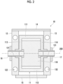
- Fig. 2 is a sectional view illustrating an example of a configuration of an intermediate mold 10 of the mold unit 1.
- Fig. 3A is a perspective view illustrating an example of an external appearance configuration of support members 12 and 13, a connection member 14, and a coupling member 15 among a plurality of members constituting the intermediate mold 10.
- Fig. 3B is a front view illustrating an example of the external appearance configuration of the support members 12 and 13, the connection member 14, and the coupling member 15 among the plurality of members constituting the intermediate mold 10.
- the injection molding machine 100 illustrated in Figs. 1A and 1B is a molding machine used for injection blow molding.
- the injection blow molding refers to a molding method in which injection molding and blow molding are performed in two stages. In the injection blow molding, first, a preform serving as a base form of a product is molded in the injection molding. Then, in the blow molding, a product is molded by sending air to the inside of the preform and expanding the preform.
- the injection molding machine 100 is mounted with the mold unit 1 that enables injection blow molding.
- the mold unit 1 includes a stationary-side mold 30, a movable-side mold 20, and the intermediate mold 10 disposed between the stationary-side mold 30 and the movable-side mold 20.
- the mold unit 1 performs injection molding by mold clamping between the stationary-side mold 30 and the intermediate mold 10, and performs blow molding by mold clamping between the movable-side mold 20 and the intermediate mold 10.
- the intermediate mold 10 includes a mold portion, a support portion, the connection member 14, and shaft bodies 16 and 17.
- the mold portion includes a rotating frame body 11 and plate groups 115 and 116 including a plurality of mold plates.
- the support portion includes the support members 12 and 13 and the coupling member 15.
- the rotating frame body 11 in the mold portion is a metal frame body that is rotated by a rotary shaft 200, and includes a top-side portion 111, a bottom-side portion 112, a first side portion 113, and a second side portion 114, which are coupled to each other by a bolt or the like.
- the plate groups 115 and 116 including the plurality mold plates are detachably attached to the rotating frame body 11.
- the description is made in which the rotating frame body 11 is assembled with the plate-shaped top-side portion 111, the bottom-side portion 112, the first side portion 113, and the second side portion 114 (the boundary between the respective portions is not illustrated).
- the top-side portion 111, the bottom-side portion 112, the first side portion 113, and the second side portion 114 may be integrally formed, or may be formed by assembling a plurality of components.
- the shaft body 16 that is rotated by the rotary shaft 200 is detachably attached to the first side portion 113 of the rotating frame body 11.
- the shaft body 17 that is rotated by the rotary shaft 200 is detachably attached to the second side portion 114 of the rotating frame body 11.
- the shaft body 16 and the shaft body 17 are removed outward of the rotating frame body 11 after a bearing (not illustrated) provided in each of the rotating frame body 11 and the support members 12 and 13 is removed outward.
- the plate group 115 is also rotated.
- the plate group 116 is detachably attached to the rotating frame body 11 via a member (not illustrated).
- the plate group 116 is configured not to be rotated, unlike the plate group 115.
- the support member 12 is a support member that supports the first side portion 113 of the rotating frame body 11 in an attachable and detachable manner.
- the support member 12 includes a bearing portion 121 that supports the shaft body 16 attached to the first side portion 113 of the rotating frame body 11 in an attachable and detachable manner.
- the support member 12 includes through-holes 122 for sliding a tie bar (not illustrated) that guides an opening and closing operation of the mold.
- the through-hole 122 is a hole that penetrates in a direction perpendicular to an axial direction (a direction in which the mold is opened and closed), and is provided in the vicinity of an end portion on each of a top side and a bottom side of the support member 12 in a top-bottom direction.
- the connection member 14 and the coupling member 15 are detachably connected to the support member 12.
- the support member 12 is fixed to the inside of the injection molding machine 100 via the coupling member 15.
- the support member 13 is a support member that supports the second side portion 114 of the rotating frame body 11 in an attachable and detachable manner.
- the support member 13 includes a bearing portion 131 that supports the shaft body 17 attached to the second side portion 114 of the rotating frame body 11 in an attachable and detachable manner.
- the support member 13 includes through-holes 132 for sliding the tie bar.
- the through-hole 132 is a hole that penetrates in the direction perpendicular to the axial direction, and is provided in the vicinity of an end portion on each of a top side and a bottom side of the support member 13.
- the connection member 14 and the coupling member 15 are detachably connected to the support member 13.
- the support member 13 is fixed to the inside of the injection molding machine 100 via the coupling member 15.
- connection member 14 is a member detachably connected to the top sides of the support member 12 and the support member 13. Each of a connecting part between the connection member 14 and the support member 12 and a connecting part between the connection member 14 and the support member 13 is detachably connected by a bolt 141.
- the coupling member 15 is a member detachably connected to the bottom sides of the support member 12 and the support member 13, and is detachably fixed to the inside of the injection molding machine 100. Therefore, each of the support member 12 and the support member 13 connected to the coupling member 15 is fixed to a predetermined position inside the injection molding machine 100 via the coupling member 15. Therefore, the coupling member 15 functions as a member that performs positioning of the support member 12 and the support member 13.
- the shaft body 16 and the shaft body 17 are members that are rotated by the rotary shaft 200.
- the shaft body 16 is supported by the bearing portion 121 of the support member 12 in a state of being attached to the first side portion 113 of the rotating frame body 11.
- the shaft body 17 is supported by the bearing portion 131 of the support member 13 in a state of being attached to the second side portion 114 of the rotating frame body 11.
- a drive unit (not illustrated) for rotating the shaft body 17 is connected to the shaft body 17.
- the rotating frame body 11, the support member 12, the support member 13, the connection member 14, the coupling member 15, the shaft body 16, and the shaft body 17 that constitute the intermediate mold 10 can be disassembled. Therefore, for example, in a case of performing the maintenance of the plate groups 115 and 116 attached to the rotating frame body 11, each of the shaft bodies 16 and 17 and the connection member 14 which are attached to the support member 12 and the support member 13 are removed. In a case where the connection member 14 is removed, a space can be secured on the top side of the intermediate mold 10.
- the rotating frame body 11 to which the plate groups 115 and 116 are attached is taken out and maintenance is performed by using the space.
- a cover on the top side of the injection molding machine 100 illustrated in Figs. 1A and 1B is slid, the rotating frame body 11 to which the plate groups 115 and 116 are attached is taken out through the space opened by the sliding, and the maintenance is performed.
- a window portion 40 for visualizing the inside or the like may be provided in the cover on the top side, but in a case where the window portion 40 has a sufficient width for performing the maintenance, the maintenance may be performed by opening the window portion 40 and taking out the rotating frame body 11 to which the plate groups 115 and 116 are attached, from the window portion 40.
- the details of specific work in a case of taking out the rotating frame body 11 to which the plate groups 115 and 116 are attached will be described later with reference to Fig. 4 .
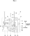
- Fig. 4 is a view illustrating a state of attachment and detachment work when maintenance of the intermediate mold 10 is performed.
- Fig. 4 illustrates a part of the intermediate mold 10 on which a jig for connecting a lifting bar 92 and the intermediate mold 10 is mounted, the lifting bar 92 supporting the top-side portion 111 of the intermediate mold 10 from the bottom side in the top-bottom direction to stabilize a lifting state, such as a posture when the rotating frame body 11 is lifted to the top side.
- a lifting state such as a posture when the rotating frame body 11 is lifted to the top side.
- a cylindrical jig 90 is attached to the intermediate mold 10 to connect and fix the top-side portion 111 of the rotating frame body 11 and the connection member 14 to each other.
- a cylindrical jig 96 is attached to connect and fix the lifting bar 92 and the plate group 116 to each other.
- the jig 90 is attached by using a bolt 91
- the jig 96 is attached by using a bolt 97.
- the plate group 116 and the plate group 115 (hereinafter, referred to as "plate group 116 or the like" in the description of Fig. 4 ) are fixed to the lifting bar 92 via the jig 96
- the lifting bar 92 is fixed to the top-side portion 111 or the connection member 14 via the bolt 91 or the jig 90.
- the plate group 116 or the like is fixed to the lifting bar 92 via the jig 96, and the lifting bar 92 is fixed to the top-side portion 111 or the connection member 14 via the bolt 91 or the jig 90.
- the connection member 14 is larger than the support members 12 and 13, and thus, the connection member 14 can support the plate group 116 or the like even in a state where the shaft bodies 16 and 17 are not provided.
- the rotating frame body 11 to which the plate group 116 or the like is attached and the connection member 14 can be taken out integrally. In addition, it is possible to prevent the rotating frame body 11 from being rotated when the rotating frame body 11 and the connection member 14 are taken out or moved.
- the top-side portion 111 of the rotating frame body 11 and the connection member 14 are connected by using the jig 90, but the present invention is not limited thereto.
- the top-side portion 111 of the rotating frame body 11 and the lifting bar 92 may be connected to each other. In this case, the rotating frame body 11 can be taken out separately from the connection member 14 through the space on the top side formed by removing the connection member 14.
- the lifting bar 92 is disposed at a position where the top-side portion 111 of the rotating frame body 11 can be supported from the bottom side.
- a hanging tool 93 is attached to each of both end portions of the lifting bar 92.
- a hook 95 of a crane 94 is hung on each hanging tool 93, and the hanging tool 93 is in a state where the hanging tool 93 can be lifted to the top side.
- the shaft body 16 is removed from the first side portion 113 of the rotating frame body 11, and the shaft body 17 is removed from the second side portion 114 of the rotating frame body 11.
- the connection member 14 is removed from the support members 12 and 13. Accordingly, the combination of the rotating frame body 11 to which the plate group 116 or the like is attached and the connection member 14 is in a free state toward the top side, and a sufficient space is secured on the top side of the intermediate mold 10.
- the rotating frame body 11 to which the plate group 116 or the like is attached and the connection member 14 are lifted integrally using the crane 94, and are taken out to the outside of the injection molding machine 100.
- the rotating frame body 11 and the connection member 14 are taken out to the outside from the window portion 40 (refer to Figs. 1A and 1B ) of the injection molding machine 100. After that, maintenance is started.
- the jig 90 is attached to the top-side portion 111 of the rotating frame body 11 and the connection member 14 again.
- the lifting bar 92 is disposed on the bottom side of the top-side portion 111, and the jig 96 is attached to the lifting bar 92 and the plate group 116 again.
- the rotating frame body 11 to which the plate group 116 or the like is attached and the connection member 14 are lifted integrally by using the crane 94, and are returned to the inside of the injection molding machine 100.
- the rotating frame body 11 and the connection member 14 are returned to the inside from the window portion 40 of the injection molding machine 100.
- the rotating frame body 11 and the connection member 14 are attached to the support members 12 and 13 fixed to the injection molding machine 100, and finally, the lifting bar 92 and the jig 90 are removed. In this manner, the attachment and detachment work when maintenance of the intermediate mold 10 is performed is completed.
- the intermediate mold, the mold unit, and the injection molding machine to which the present invention is applied may only need to have the following configuration and can take various embodiments.
- the intermediate mold 10 is the intermediate mold disposed between the stationary-side mold 30 and the movable-side mold 20 in the mold unit 1 of the injection molding machine 100, and the intermediate mold 10 includes the support portion (the support member 12, thee support member 13, and the coupling member 15) that supports, in an attachable and detachable manner, both sides (the first side portion 113 and the second side portion 114) of the rotary shaft 200 of the mold portion (the rotating frame body 11 to which the plate group 115 is attached) that is rotated; and the connection member 14 that is detachably connected to the top side of the support portion in the top-bottom direction, in which in a case where the mold portion is attached to and detached from the support portion, the mold portion is attached and detached through a space (space formed on the top side of the intermediate mold 10) formed by removing the connection member 14 from the support portion.
- the support portion the support member 12, thee support member 13, and the coupling member 15
- the connection member 14 that is detachably connected to the top side of the support portion in the top-
- connection member 14 connected to the top side of the support portion supporting the rotary shaft 200 of the mold portion is attachable and detachable, and when the mold portion is attached to and detached from the support portion, the mold portion is attached to and detached through a space formed by removing the connection member 14 from the support portion.
- a space for taking out the mold portion to the outside of the injection molding machine 100 during maintenance can be secured on the top side.
- connection member 14 and the mold portion can be taken out integrally with each other, the maintainability is improved.
- the present embodiment is superior in that the mold portion is attachable and detachable through the space formed on the top side by removing the connection member 14, as compared to a case where the intermediate mold is disassembled into a plurality of plates to be attached and detached in a direction other than the top side (for example, in an axial direction or a direction in which the mold is opened and closed) in order to take out the intermediate mold to the outside of the injection molding machine, or a case where a member for supporting the mold portion of the intermediate mold from both sides with the bearing is disassembled to be attached and detached in a direction other than the top side.
- the size of the intermediate mold 10 can be made compact, and thus the size of the injection molding machine 100 can also be made compact.
- the support portion may be able to be disassembled into the support member 12 that supports the first side of the rotary shaft 200 and the support member 13 that supports the second side of the rotary shaft 200, and may be fixed to the injection molding machine 100.
- the support portion is fixed to the injection molding machine in a state where the support portion is able to be disassembled into the support member 12 and the support member 13, and therefore, the attachment and detachment of the shaft body during the maintenance of the mold portion is facilitated.
- the support portion may be able to be disassembled into the support member 12, the support member 13, and the coupling member 15 that performs positioning of the support member 12 and the support member 13.
- the support portion is able to be disassembled into the support member 12, the support member 13, and the coupling member 15, and the coupling member 15 performs positioning of the support member 12 and the support member 13.
- the support member 12 and the support member 13 are disassembled from each other at the time of maintenance of the mold portion, the installation work after the maintenance is facilitated.
- the support portion may be an integral structure (a structure that is not disassembled into the support member 12, the support member 13, and the coupling member 15), and may be fixed to the injection molding machine 100.
- the support portion has an integral structure and is fixed to the injection molding machine 100, and thus, even in a case where the mold portion is taken out of the injection molding machine 100 during maintenance, the support portion remains in a state of being fixed to the inside of the injection molding machine 100.
- the maintenance of the mold portion can be performed outside the injection molding machine 100 while maintaining the state.
- the support portion may support, in an attachable and detachable manner, each of the shaft bodies 16 and 17 detachably attached to both sides of the mold portion, respectively.
- the support portion supports, in an attachable and detachable manner, each of the shaft bodies 16 and 17 detachably attached to both sides of the mold portion, respectively.
- the shaft body does not penetrate the mold portion, and therefore, it is not necessary to perform work of inserting and removing the shaft body during maintenance.
- the jig 90 that fixes the connection member 14 and the mold portion may be able to be attached to and detached from the connection member 14 and the mold portion.
- connection member 14 and the mold portion when the connection member 14 and the mold portion are removed from the support portion, the connection member 14 and the mold portion can be taken out integrally.
- the mold unit 1 is the mold unit of the injection molding machine 100, in which the intermediate mold 10 disposed between the stationary-side mold 30 and the movable-side mold 20 includes the support portion (the support member 12, the support member 13, and the coupling member 15) that supports, in an attachable and detachable manner, both sides (the first side portion 113 and the second side portion 114) of the rotary shaft 200 of the mold portion (the rotating frame body 11 to which the plate group 115 is attached) that is rotated, and the connection member 14 that is detachably connected to the top side of the support portion in the top-bottom direction, and in a case where the mold portion is attached to and detached from the support portion, the mold portion is attached and detached through a space (space formed on the top side of the intermediate mold 10) formed by removing the connection member 14 from the support portion.
- the support portion the support member 12, the support member 13, and the coupling member 15
- connection member 14 connected to the top side of the support portion supporting the rotary shaft 200 of the mold portion is attachable and detachable, and when the mold portion is attached to and detached from the support portion, the mold portion is attached to and detached through a space formed by removing the connection member 14 from the support portion.
- a space for taking out the mold portion to the outside of the injection molding machine 100 during maintenance can be secured on the top side.
- connection member 14 and the mold portion can be taken out integrally with each other, the maintainability is improved.
- the present embodiment is superior in that the mold portion is attachable and detachable through the space formed on the top side by removing the connection member 14, as compared to a case where the intermediate mold is disassembled into a plurality of plates to be attached and detached in a direction other than the top side (for example, in an axial direction or a direction in which the mold is opened and closed) in order to take out the intermediate mold to the outside of the injection molding machine, or a case where a member for supporting the mold portion of the intermediate mold from both sides with the bearing is disassembled to be attached and detached in a direction other than the top side.
- the size of the intermediate mold 10 can be made compact, and thus the size of the injection molding machine 100 can also be made compact.
- the injection molding machine 100 is the injection molding machine mounted with the mold unit 1 including the stationary-side mold 30, the movable-side mold 20, and the intermediate mold 10 disposed between the stationary-side mold 30 and the movable-side mold 20, in which the intermediate mold 10 includes the support portion (the support member 12, the support member 13, and the coupling member 15) that supports, in an attachable and detachable manner, both sides (the first side portion 113 and the second side portion 114) of the rotary shaft 200 of the mold portion that is rotated, and the connection member 14 that is detachably connected to the top side of the support portion in the top-bottom direction, and in a case where the mold portion is attached to and detached from the support portion, the mold portion is attached and detached through a space (space formed on the top side of the intermediate mold 10) formed by removing the connection member 14 from the support portion.
- the intermediate mold 10 includes the support portion (the support member 12, the support member 13, and the coupling member 15) that supports, in an attachable and detachable manner, both sides (the first side
- connection member 14 connected to the top side of the support portion supporting the rotary shaft 200 of the mold portion is attachable and detachable, and when the mold portion is attached to and detached from the support portion, the mold portion is attached to and detached through a space formed by removing the connection member 14 from the support portion.
- a space for taking out the mold portion to the outside of the injection molding machine 100 during maintenance can be secured on the top side.
- connection member 14 and the mold portion can be taken out integrally with each other, the maintainability is improved.
- the present embodiment is superior in that the mold portion is attachable and detachable through the space formed on the top side by removing the connection member 14, as compared to a case where the intermediate mold is disassembled into a plurality of plates to be attached and detached in a direction other than the top side (for example, in an axial direction or a direction in which the mold is opened and closed) in order to take out the intermediate mold to the outside of the injection molding machine, or a case where a member for supporting the mold portion of the intermediate mold from both sides with the bearing is disassembled to be attached and detached in a direction other than the top side.
- the size of the intermediate mold 10 can be made compact, and thus the size of the injection molding machine 100 can also be made compact.
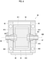
- Fig. 5 is a sectional view illustrating an example of a configuration of an intermediate mold 50 of a mold unit according to a second embodiment.
- the rotating frame body 11 of the intermediate mold 10 according to the first embodiment described above is configured, for example, as illustrated in Fig. 2 described above, such that the shaft bodies 16 and 17 are attached to the first side portion 113 and the second side portion 114, respectively.
- a rotating frame body 51 of the intermediate mold 50 according to the second embodiment is configured such that a shaft body 56 penetrates a first side portion 513, a plate group 516, and a second side portion 514.
- the shaft body 56 is a member that is rotated by a rotary shaft 500.
- the shaft body 56 is supported by a bearing portion 521 of a support member 52 and a bearing portion 531 of a support member 53 in a state of penetrating the rotating frame body 51 and the plate group 516.
- a drive unit (not illustrated) for rotating the shaft body 56 is connected to the shaft body 56.
- the configurations of the support member 52, the support member 53, a connection member 54, and a coupling member 55 according to the second embodiment are the same as the configurations of the support member 12, the support member 13, the connection member 14, and the coupling member 15 according to the first embodiment described above.
- the support member 52 is a member including the bearing portion 521 that supports the first side portion 513 of the rotating frame body 51 in an attachable and detachable manner via the shaft body 56, and a through-hole 522 for sliding a tie bar (not illustrated).
- the support member 53 is a member including the bearing portion 531 that supports the second side portion 514 of the rotating frame body 51 in an attachable and detachable manner via the shaft body 56, and a through-hole 532 for sliding the tie bar.
- connection member 54 is a member detachably connected to the top sides of the support member 52 and the support member 53.
- Each of a connecting part between the connection member 54 and the support member 52 and a connecting part between the connection member 54 and the support member 53 is detachably connected by a bolt (not illustrated).
- the coupling member 55 is a member detachably connected to the bottom sides of the support member 52 and the support member 53, and is detachably fixed to the inside of the injection molding machine 100 (refer to Figs. 1A and 1B ).
- the coupling member 55 functions as a member that performs positioning of the support member 52 and the support member 53.
- the rotating frame body 51, the support member 52, the support member 53, the connection member 54, the coupling member 55, and the shaft body 56 that constitute the intermediate mold 50 can be disassembled. Therefore, in a case of performing maintenance of the plate group 516 attached to the rotating frame body 51 and the plate group (hereinafter, referred to as "plate group 516 or the like") (not illustrated) that is rotated together with the rotating frame body 51, the shaft body 56 penetrating the support member 52, the rotating frame body 51, the plate group 516, and the support member 53 is pulled out, and the connection member 54 is removed from the support members 52 and 53. In a case where the connection member 54 is removed, a space can be secured on the top side of the intermediate mold 50.
- the rotating frame body 51 to which the plate group 516 or the like is attached is taken out and maintenance is performed by using the space.
- the rotating frame body 51 to which the plate group 516 or the like is attached is taken out through the window portion 40 on the top side of the injection molding machine 100 illustrated in Figs. 1A and 1B , and the maintenance is performed.
- the details of specific work when the rotating frame body 51 to which the plate group 516 or the like is attached is taken out are basically the same as the contents described with reference to Fig. 4 described above, except for the work of pulling out the shaft body 56, and the description thereof will be omitted.
- the intermediate mold 50 is the intermediate mold disposed between the stationary-side mold 30 and the movable-side mold 20 in the mold unit 1 of the injection molding machine 100, and the intermediate mold 50 includes the support portion (the support member 52, thee support member 53, and the coupling member 55) that supports, in an attachable and detachable manner, both sides (the first side portion 513 and the second side portion 514) of the rotary shaft 500 of the mold portion (the rotating frame body 51 to which the plate group (not illustrated) rotated together with the rotating frame body 51 is attached) that is rotated; and the connection member 54 that is detachably connected to the top side of the support portion in a top-bottom direction, in which in a case where the mold portion is attached to and detached from the support portion, the mold portion is attached and detached through a space (space formed on the top side of the intermediate mold 50) formed by removing the connection member 54 from the support portion.
- the support portion the support member 52, thee support member 53, and the coupling member 55
- the support portion may support both sides (the first side portion 513 and the second side portion 514) of the mold portion in an attachable and detachable manner via the shaft body 56 penetrating the mold portion.
- the support portion supports both sides of the mold portion in an attachable and detachable manner via the shaft body 56 penetrating the mold portion, the support portion is different from a configuration in which the shaft bodies are respectively attached to both sides of the mold portion (for example, the configuration of Fig. 2 ). Therefore, the total of two times of the attachment and detachment work for respectively attaching and detaching the shaft bodies to and from both sides of the mold portion at the time of maintenance can be reduced to one time of the attachment and detachment work.
- the rotating frame body 11 of the intermediate mold 10 is configured, for example, as illustrated in Fig. 2 described above, such that, with respect to the first side portion 113 and the second side portion 114, the shaft bodies 16 and 17 are respectively inserted into the bearing portions 121 and 131 of the support members 12 and 13 respectively via the first side portion 113 and the second side portion 114 of the rotating frame body 11 from the inside of the intermediate mold 10, and are respectively attached to the first side portion 113 and the second side portion 114, but the present invention is not limited thereto.
- a configuration may be adopted in which each of the shaft bodies does not penetrate the first side portion and the second side portion.
- Fig. 6 is a sectional view illustrating an example of a configuration of an intermediate mold 60 of a mold unit according to a third embodiment.
- the intermediate mold 60 illustrated in Fig. 6 is configured such that the mold portion (a plate group 616 and a rotating frame body 61 to which a plate group (not illustrated) that is rotated together with the rotating frame body 61 is attached) is removed in a state where shaft bodies 66 and 67 are respectively supported by bearing portions 621 and 631.
- the shaft bodies 66 and 67 are detachably attached to the mold portion from the outside.
- an end portion of the shaft body 66 is detachably fixed to a first side portion 613 of the rotating frame body 61 by a bolt or the like
- an end portion of the shaft body 67 is detachably fixed to a second side portion 614 of the rotating frame body 61 by a bolt or the like.
- Each of the bearing portions 621 and 631 is provided with a storage space (not illustrated) capable of storing an inner end portion of each of the shaft bodies 66 and 67. Accordingly, in a case of taking out the mold portion, the shaft bodies 66 and 67 are removed from the mold portion and stored in the storage spaces.
- each of the shaft bodies 66 and 67 can be retracted from the trajectory of each of the first side portion 613 and the second side portion 614 of the rotating frame body 61. As a result, it is not necessary to take out each of the shaft bodies 66 and 67 at the time of maintenance of the mold portion, and thus work efficiency can be improved.
- the mold portion without removing the shaft bodies 16 and 17 by respectively providing the storage spaces capable of respectively storing the shaft bodies 16 and 17 in the bearing portions 121 and 131 according to the first embodiment illustrated in Fig. 2 described above.
- the portions of the shaft bodies 16 and 17 protruding in the direction toward the mold portion from the support portion are longer as compared with a case of the shaft bodies 66 and 67 according to the third embodiment illustrated in Fig. 6 , and therefore, a large storage space is required.
- the portions of the shaft bodies 66 and 67 of Fig. 6 protruding in the direction toward the mold portion from the support portion are short, and therefore, the storage space can be reduced.
- the shaft bodies 16 and 17 of Fig. 2 include portions disposed inside the mold portion, in a case of removing the shaft bodies 16 and 17, the first side portion 113 and the second side portion 114 of the rotating frame body 11 are divided to facilitate the removal of the shaft bodies 16 and 17.
- the shaft bodies 66 and 67 of Fig. 6 do not include portions disposed inside the mold portion, the shaft bodies 66 and 67 can be easily removed without dividing the first side portion 613 and the second side portion 614 of the rotating frame body 61.
- the third embodiment is more preferable than the first embodiment.
- a removable portion (not illustrated) may be provided in each of the bearing portions 621 and 631.
- each of the shaft bodies 66 and 67 is removed outward from each of support members 62 and 63.
- the configurations of the support member 62, the support member 63, a connection member 64, and a coupling member 65 are the same as the configurations of the support member 12, the support member 13, the connection member 14, and the coupling member 15 according to the first embodiment described above. That is, the support member 62 is a member including the bearing portion 621 that supports the first side portion 613 of the rotating frame body 61 in an attachable and detachable manner, and a through-hole 622 for sliding a tie bar (not illustrated). In addition, the support member 63 is a member including the bearing portion 631 that supports the second side portion 614 of the rotating frame body 61 in an attachable and detachable manner, and a through-hole 632 for sliding the tie bar.
- connection member 64 is a member detachably connected to the top sides of the support member 62 and the support member 63.
- Each of a connecting part between the connection member 64 and the support member 62 and a connecting part between the connection member 64 and the support member 63 is detachably connected by a bolt (not illustrated).
- the coupling member 65 is a member detachably connected to the bottom sides of the support member 62 and the support member 63, and is detachably fixed to the inside of the injection molding machine 100 (refer to Figs. 1A and 1B ).
- the coupling member 65 functions as a member that performs positioning of the support member 62 and the support member 63.
- the intermediate mold 60 according to the third embodiment illustrated in Fig. 6 includes more rotating portions than the intermediate mold 10 according to the first embodiment illustrated in Fig. 2 and the intermediate mold 50 according to the second embodiment illustrated in Fig. 5 , and therefore, the weight of the plate group 616 and the plate group or the like (not illustrated) that is rotated together with the rotating frame body 61 is added to the rotating portions.
- the first embodiment and the second embodiment are more preferable than the third embodiment.
Landscapes
- Engineering & Computer Science (AREA)
- Mechanical Engineering (AREA)
- Manufacturing & Machinery (AREA)
- Injection Moulding Of Plastics Or The Like (AREA)
- Moulds For Moulding Plastics Or The Like (AREA)
Abstract
Maintainability of an intermediate mold (10) that constitutes a mold unit (1) is improved.An intermediate mold (10) disposed between a stationary-side mold (30) and a movable-side mold (20) in a mold unit (1) of an injection molding machine (100) includes support members (12, 13) that support, in an attachable and detachable manner, both sides of a rotary shaft (200, 500, 600) of a mold portion that is rotated; and a connection member (14) that is detachably connected to top sides of the support members (12, 13) in a top-bottom direction, in which in a case where the mold portion is attached to and detached from the support members (12, 13), the mold portion is attached and detached through a space formed by removing the connection member (14) from the support members (12, 13).
Description
- The present invention relates to an intermediate mold, a mold unit, and an injection molding machine.
- As a mold unit that constitutes an injection molding machine, there is a mold unit in which an intermediate mold is disposed between a stationary-side mold and a movable-side mold. In addition, as the intermediate mold, there is a mold that is rotatable in a state of being supported by a support frame (for example,
Japanese Patent No. 4283181 - Since the support frame constituting the intermediate mold in the related art has an integral structure, the intermediate mold may be disassembled into a plurality of plates in order to take out the intermediate mold to the outside of the injection molding machine. However, in this case, a member for sealing a pipe path needs to be disposed on a plate mating surface, and in a case where the size of the intermediate mold is increased in order to secure a disposition location thereof, the size of the injection molding machine also needs to be increased. In addition, in a case where the intermediate mold cannot be disassembled into a plurality of members in terms of design, even in a case where the intermediate mold is removed from the support frame, the support frame gets in the way so that the intermediate mold cannot be taken out from the injection molding machine.
- An object of the present invention is to improve maintainability of the intermediate mold that constitutes the mold unit.
- According to the present invention completed for the above purpose, there is provided an intermediate mold disposed between a stationary-side mold and a movable-side mold in a mold unit of an injection molding machine, the intermediate mold including a support portion that supports, in an attachable and detachable manner, both sides of a rotary shaft of a mold portion that is rotated; and a connection member that is detachably connected to a top side of the support portion in a top-bottom direction, in which in a case where the mold portion is attached to and detached from the support portion, the mold portion is attached and detached through a space formed by removing the connection member from the support portion.
- Here, the support portion may be able to be disassembled into a first support member that supports one side of the rotary shaft, and a second support member that supports the other side of the rotary shaft, and may be fixed to the injection molding machine.
- In addition, the support portion may be able to be disassembled into the first support member, the second support member, and a coupling member that performs positioning of the first support member and the second support member.
- In addition, the support portion may have an integral structure, and may be fixed to the injection molding machine.
- In addition, the support portion may support, in an attachable and detachable manner, shaft bodies that are detachably attached to both sides of the mold portion, respectively.
- In addition, the support portion may support, in an attachable and detachable manner, both sides of a shaft body penetrating the mold portion.
- In addition, a jig that fixes the connection member and the mold portion may be able to be attached to and detached from the connection member and the mold portion.
- In addition, an aspect of the present invention is a mold unit of an injection molding machine, in which an intermediate mold disposed between a stationary-side mold and a movable-side mold includes a support portion that supports, in an attachable and detachable manner, both sides of a rotary shaft of a mold portion that is rotated, and a connection member that is detachably connected to a top side of the support portion in a top-bottom direction, and in a case where the mold portion is attached to and detached from the support portion, the mold portion is attached and detached through a space formed by removing the connection member from the support portion.
- In addition, another aspect of the present invention is an injection molding machine mounted with a mold unit including a stationary-side mold, a movable-side mold, and an intermediate mold disposed between the stationary-side mold and the movable-side mold, in which the intermediate mold includes a support portion that supports, in an attachable and detachable manner, both sides of a rotary shaft of a mold portion that is rotated, and a connection member that is detachably connected to a top side of the support portion in a top-bottom direction, and in a case where the mold portion is attached to and detached from the support portion, the mold portion is attached and detached through a space formed by removing the connection member from the support portion.
- According to the present invention, it is possible to improve the maintainability of the intermediate mold that constitutes the mold unit.
-
-
Figs. 1A and 1B are perspective views illustrating an example of an external appearance configuration of each of an injection molding machine according to a first embodiment and a part of a mold unit mounted on the injection molding machine. -
Fig. 2 is a sectional view illustrating an example of a configuration of an intermediate mold of the mold unit. -
Fig. 3A is a perspective view illustrating an example of an external appearance configuration of support members, a connection member, and a coupling member among a plurality of members constituting the intermediate mold. -
Fig. 3B is a front view illustrating an example of the external appearance configuration of the support member, the connection member, and the coupling member among the plurality of members constituting the intermediate mold. -
Fig. 4 is a view illustrating a state of attachment and detachment work when maintenance of the intermediate mold is performed. -
Fig. 5 is a sectional view illustrating an example of an external appearance configuration of an intermediate mold of a mold unit according to a second embodiment. -
Fig. 6 is a sectional view illustrating an example of a configuration of an intermediate mold of a mold unit according to a third embodiment. - Hereinafter, embodiments of the present invention will be described in detail with reference to the accompanying drawings.
-
Figs. 1A and 1B are perspective views illustrating an example of an external appearance configuration of each of aninjection molding machine 100 according to a first embodiment and a part of amold unit 1 mounted on theinjection molding machine 100. -
Fig. 2 is a sectional view illustrating an example of a configuration of anintermediate mold 10 of themold unit 1. -
Fig. 3A is a perspective view illustrating an example of an external appearance configuration ofsupport members connection member 14, and acoupling member 15 among a plurality of members constituting theintermediate mold 10.Fig. 3B is a front view illustrating an example of the external appearance configuration of thesupport members connection member 14, and thecoupling member 15 among the plurality of members constituting theintermediate mold 10. - The
injection molding machine 100 illustrated inFigs. 1A and 1B is a molding machine used for injection blow molding. The injection blow molding refers to a molding method in which injection molding and blow molding are performed in two stages. In the injection blow molding, first, a preform serving as a base form of a product is molded in the injection molding. Then, in the blow molding, a product is molded by sending air to the inside of the preform and expanding the preform. - The
injection molding machine 100 is mounted with themold unit 1 that enables injection blow molding. Themold unit 1 includes a stationary-side mold 30, a movable-side mold 20, and theintermediate mold 10 disposed between the stationary-side mold 30 and the movable-side mold 20. Themold unit 1 performs injection molding by mold clamping between the stationary-side mold 30 and theintermediate mold 10, and performs blow molding by mold clamping between the movable-side mold 20 and theintermediate mold 10. - As illustrated in
Figs. 1A to 2 , theintermediate mold 10 includes a mold portion, a support portion, theconnection member 14, andshaft bodies frame body 11 andplate groups support members coupling member 15. The rotatingframe body 11 in the mold portion is a metal frame body that is rotated by arotary shaft 200, and includes a top-side portion 111, a bottom-side portion 112, afirst side portion 113, and asecond side portion 114, which are coupled to each other by a bolt or the like. - In addition, the
plate groups frame body 11. In the present embodiment, the description is made in which the rotatingframe body 11 is assembled with the plate-shaped top-side portion 111, the bottom-side portion 112, thefirst side portion 113, and the second side portion 114 (the boundary between the respective portions is not illustrated). However, the top-side portion 111, the bottom-side portion 112, thefirst side portion 113, and thesecond side portion 114 may be integrally formed, or may be formed by assembling a plurality of components. - The
shaft body 16 that is rotated by therotary shaft 200 is detachably attached to thefirst side portion 113 of the rotatingframe body 11. In addition, theshaft body 17 that is rotated by therotary shaft 200 is detachably attached to thesecond side portion 114 of the rotatingframe body 11. Theshaft body 16 and theshaft body 17 are removed outward of the rotatingframe body 11 after a bearing (not illustrated) provided in each of the rotatingframe body 11 and thesupport members - In the mold portion, in a case where the rotating
frame body 11 is rotated by therotary shaft 200, theplate group 115 is also rotated. By rotating the rotatingframe body 11 to which theplate group 115 is attached, a position where the injection molding (injection molding) is performed and a position where the blow molding is performed are alternately switched. Note that theplate group 116 is detachably attached to the rotatingframe body 11 via a member (not illustrated). However, theplate group 116 is configured not to be rotated, unlike theplate group 115. - As illustrated in
Figs. 2 and3 , thesupport member 12 is a support member that supports thefirst side portion 113 of therotating frame body 11 in an attachable and detachable manner. Thesupport member 12 includes a bearingportion 121 that supports theshaft body 16 attached to thefirst side portion 113 of therotating frame body 11 in an attachable and detachable manner. In addition, thesupport member 12 includes through-holes 122 for sliding a tie bar (not illustrated) that guides an opening and closing operation of the mold. The through-hole 122 is a hole that penetrates in a direction perpendicular to an axial direction (a direction in which the mold is opened and closed), and is provided in the vicinity of an end portion on each of a top side and a bottom side of thesupport member 12 in a top-bottom direction. In addition, theconnection member 14 and thecoupling member 15 are detachably connected to thesupport member 12. Thesupport member 12 is fixed to the inside of theinjection molding machine 100 via thecoupling member 15. - As illustrated in
Figs. 2 and3 , thesupport member 13 is a support member that supports thesecond side portion 114 of therotating frame body 11 in an attachable and detachable manner. Thesupport member 13 includes a bearingportion 131 that supports theshaft body 17 attached to thesecond side portion 114 of therotating frame body 11 in an attachable and detachable manner. In addition, thesupport member 13 includes through-holes 132 for sliding the tie bar. The through-hole 132 is a hole that penetrates in the direction perpendicular to the axial direction, and is provided in the vicinity of an end portion on each of a top side and a bottom side of thesupport member 13. In addition, theconnection member 14 and thecoupling member 15 are detachably connected to thesupport member 13. Thesupport member 13 is fixed to the inside of theinjection molding machine 100 via thecoupling member 15. - The
connection member 14 is a member detachably connected to the top sides of thesupport member 12 and thesupport member 13. Each of a connecting part between theconnection member 14 and thesupport member 12 and a connecting part between theconnection member 14 and thesupport member 13 is detachably connected by abolt 141. - The
coupling member 15 is a member detachably connected to the bottom sides of thesupport member 12 and thesupport member 13, and is detachably fixed to the inside of theinjection molding machine 100. Therefore, each of thesupport member 12 and thesupport member 13 connected to thecoupling member 15 is fixed to a predetermined position inside theinjection molding machine 100 via thecoupling member 15. Therefore, thecoupling member 15 functions as a member that performs positioning of thesupport member 12 and thesupport member 13. - The
shaft body 16 and theshaft body 17 are members that are rotated by therotary shaft 200. Theshaft body 16 is supported by the bearingportion 121 of thesupport member 12 in a state of being attached to thefirst side portion 113 of therotating frame body 11. Theshaft body 17 is supported by the bearingportion 131 of thesupport member 13 in a state of being attached to thesecond side portion 114 of therotating frame body 11. A drive unit (not illustrated) for rotating theshaft body 17 is connected to theshaft body 17. - The
rotating frame body 11, thesupport member 12, thesupport member 13, theconnection member 14, thecoupling member 15, theshaft body 16, and theshaft body 17 that constitute theintermediate mold 10 can be disassembled. Therefore, for example, in a case of performing the maintenance of theplate groups rotating frame body 11, each of theshaft bodies connection member 14 which are attached to thesupport member 12 and thesupport member 13 are removed. In a case where theconnection member 14 is removed, a space can be secured on the top side of theintermediate mold 10. - In a case where a space is secured on the top side of the
intermediate mold 10, therotating frame body 11 to which theplate groups injection molding machine 100 illustrated inFigs. 1A and 1B is slid, therotating frame body 11 to which theplate groups window portion 40 for visualizing the inside or the like may be provided in the cover on the top side, but in a case where thewindow portion 40 has a sufficient width for performing the maintenance, the maintenance may be performed by opening thewindow portion 40 and taking out therotating frame body 11 to which theplate groups window portion 40. The details of specific work in a case of taking out therotating frame body 11 to which theplate groups Fig. 4 . -
Fig. 4 is a view illustrating a state of attachment and detachment work when maintenance of theintermediate mold 10 is performed. -
Fig. 4 illustrates a part of theintermediate mold 10 on which a jig for connecting a liftingbar 92 and theintermediate mold 10 is mounted, the liftingbar 92 supporting the top-side portion 111 of theintermediate mold 10 from the bottom side in the top-bottom direction to stabilize a lifting state, such as a posture when therotating frame body 11 is lifted to the top side. Note that, inFig. 4 , the illustration of the support member 12 (refer toFig. 2 ) and the plate group 115 (refer toFig. 1B ) is omitted in order to make it easy to see a state where the jig is mounted. - In a case where maintenance of the
intermediate mold 10 is performed, acylindrical jig 90 is attached to theintermediate mold 10 to connect and fix the top-side portion 111 of therotating frame body 11 and theconnection member 14 to each other. In addition, acylindrical jig 96 is attached to connect and fix the liftingbar 92 and theplate group 116 to each other. Thejig 90 is attached by using abolt 91, and thejig 96 is attached by using abolt 97. Accordingly, theplate group 116 and the plate group 115 (not illustrated) (hereinafter, referred to as "plate group 116 or the like" in the description ofFig. 4 ) are fixed to the liftingbar 92 via thejig 96, and the liftingbar 92 is fixed to the top-side portion 111 or theconnection member 14 via thebolt 91 or thejig 90. - That is, in order to remove the
plate group 116 or the like from theintermediate mold 10 during maintenance, it is necessary to create a state where theshaft bodies side portion 111, the bottom-side portion 112, thefirst side portion 113, and thesecond side portion 114 of therotating frame body 11 and theplate group 116 or the like are placed on theshaft bodies plate group 116 or the like is fixed to the liftingbar 92 via thejig 96, and the liftingbar 92 is fixed to the top-side portion 111 or theconnection member 14 via thebolt 91 or thejig 90. Theconnection member 14 is larger than thesupport members connection member 14 can support theplate group 116 or the like even in a state where theshaft bodies - With the above configuration, the
rotating frame body 11 to which theplate group 116 or the like is attached and theconnection member 14 can be taken out integrally. In addition, it is possible to prevent therotating frame body 11 from being rotated when therotating frame body 11 and theconnection member 14 are taken out or moved. In addition, in the example ofFig. 4 , the top-side portion 111 of therotating frame body 11 and theconnection member 14 are connected by using thejig 90, but the present invention is not limited thereto. For example, the top-side portion 111 of therotating frame body 11 and the liftingbar 92 may be connected to each other. In this case, therotating frame body 11 can be taken out separately from theconnection member 14 through the space on the top side formed by removing theconnection member 14. - Next, as illustrated in
Fig. 4 , the liftingbar 92 is disposed at a position where the top-side portion 111 of therotating frame body 11 can be supported from the bottom side. Note that a hangingtool 93 is attached to each of both end portions of the liftingbar 92. In addition, ahook 95 of acrane 94 is hung on each hangingtool 93, and the hangingtool 93 is in a state where the hangingtool 93 can be lifted to the top side. - Next, the
shaft body 16 is removed from thefirst side portion 113 of therotating frame body 11, and theshaft body 17 is removed from thesecond side portion 114 of therotating frame body 11. In addition, theconnection member 14 is removed from thesupport members rotating frame body 11 to which theplate group 116 or the like is attached and theconnection member 14 is in a free state toward the top side, and a sufficient space is secured on the top side of theintermediate mold 10. Next, therotating frame body 11 to which theplate group 116 or the like is attached and theconnection member 14 are lifted integrally using thecrane 94, and are taken out to the outside of theinjection molding machine 100. Specifically, therotating frame body 11 and theconnection member 14 are taken out to the outside from the window portion 40 (refer toFigs. 1A and 1B ) of theinjection molding machine 100. After that, maintenance is started. - In a case where maintenance is completed, the
jig 90 is attached to the top-side portion 111 of therotating frame body 11 and theconnection member 14 again. In addition, the liftingbar 92 is disposed on the bottom side of the top-side portion 111, and thejig 96 is attached to the liftingbar 92 and theplate group 116 again. Then, therotating frame body 11 to which theplate group 116 or the like is attached and theconnection member 14 are lifted integrally by using thecrane 94, and are returned to the inside of theinjection molding machine 100. Specifically, therotating frame body 11 and theconnection member 14 are returned to the inside from thewindow portion 40 of theinjection molding machine 100. Then, therotating frame body 11 and theconnection member 14 are attached to thesupport members injection molding machine 100, and finally, the liftingbar 92 and thejig 90 are removed. In this manner, the attachment and detachment work when maintenance of theintermediate mold 10 is performed is completed. - In summary, the intermediate mold, the mold unit, and the injection molding machine to which the present invention is applied may only need to have the following configuration and can take various embodiments.
- That is, the
intermediate mold 10 according to the first embodiment is the intermediate mold disposed between the stationary-side mold 30 and the movable-side mold 20 in themold unit 1 of theinjection molding machine 100, and theintermediate mold 10 includes the support portion (thesupport member 12,thee support member 13, and the coupling member 15) that supports, in an attachable and detachable manner, both sides (thefirst side portion 113 and the second side portion 114) of therotary shaft 200 of the mold portion (therotating frame body 11 to which theplate group 115 is attached) that is rotated; and theconnection member 14 that is detachably connected to the top side of the support portion in the top-bottom direction, in which in a case where the mold portion is attached to and detached from the support portion, the mold portion is attached and detached through a space (space formed on the top side of the intermediate mold 10) formed by removing theconnection member 14 from the support portion. - Accordingly, the
connection member 14 connected to the top side of the support portion supporting therotary shaft 200 of the mold portion is attachable and detachable, and when the mold portion is attached to and detached from the support portion, the mold portion is attached to and detached through a space formed by removing theconnection member 14 from the support portion. As a result, a space for taking out the mold portion to the outside of theinjection molding machine 100 during maintenance can be secured on the top side. In addition, since theconnection member 14 and the mold portion can be taken out integrally with each other, the maintainability is improved. - In addition, the present embodiment is superior in that the mold portion is attachable and detachable through the space formed on the top side by removing the
connection member 14, as compared to a case where the intermediate mold is disassembled into a plurality of plates to be attached and detached in a direction other than the top side (for example, in an axial direction or a direction in which the mold is opened and closed) in order to take out the intermediate mold to the outside of the injection molding machine, or a case where a member for supporting the mold portion of the intermediate mold from both sides with the bearing is disassembled to be attached and detached in a direction other than the top side. - Furthermore, unlike a case where the intermediate mold is disassembled into a plurality of plates in order to take out the intermediate mold to the outside of the injection molding machine, it is not necessary to dispose a member for sealing a pipe path on the plate mating surface, and thus it is not necessary to increase the size of the
intermediate mold 10 in order to secure a disposition location of the member for sealing the pipe path. As a result, the size of theintermediate mold 10 can be made compact, and thus the size of theinjection molding machine 100 can also be made compact. - Here, the support portion may be able to be disassembled into the
support member 12 that supports the first side of therotary shaft 200 and thesupport member 13 that supports the second side of therotary shaft 200, and may be fixed to theinjection molding machine 100. - Accordingly, the support portion is fixed to the injection molding machine in a state where the support portion is able to be disassembled into the
support member 12 and thesupport member 13, and therefore, the attachment and detachment of the shaft body during the maintenance of the mold portion is facilitated. - In addition, the support portion may be able to be disassembled into the
support member 12, thesupport member 13, and thecoupling member 15 that performs positioning of thesupport member 12 and thesupport member 13. - Accordingly, the support portion is able to be disassembled into the
support member 12, thesupport member 13, and thecoupling member 15, and thecoupling member 15 performs positioning of thesupport member 12 and thesupport member 13. As a result, for example, even in a case where thesupport member 12 and thesupport member 13 are disassembled from each other at the time of maintenance of the mold portion, the installation work after the maintenance is facilitated. - In addition, the support portion may be an integral structure (a structure that is not disassembled into the
support member 12, thesupport member 13, and the coupling member 15), and may be fixed to theinjection molding machine 100. - Accordingly, the support portion has an integral structure and is fixed to the
injection molding machine 100, and thus, even in a case where the mold portion is taken out of theinjection molding machine 100 during maintenance, the support portion remains in a state of being fixed to the inside of theinjection molding machine 100. As a result, for example, even in a case where the tie bar penetrates the support portion, the maintenance of the mold portion can be performed outside theinjection molding machine 100 while maintaining the state. - In addition, the support portion may support, in an attachable and detachable manner, each of the
shaft bodies - Accordingly, the support portion supports, in an attachable and detachable manner, each of the
shaft bodies - In addition, the
jig 90 that fixes theconnection member 14 and the mold portion may be able to be attached to and detached from theconnection member 14 and the mold portion. - Accordingly, when the
connection member 14 and the mold portion are removed from the support portion, theconnection member 14 and the mold portion can be taken out integrally. - In addition, the
mold unit 1 according to the first embodiment is the mold unit of theinjection molding machine 100, in which theintermediate mold 10 disposed between the stationary-side mold 30 and the movable-side mold 20 includes the support portion (thesupport member 12, thesupport member 13, and the coupling member 15) that supports, in an attachable and detachable manner, both sides (thefirst side portion 113 and the second side portion 114) of therotary shaft 200 of the mold portion (therotating frame body 11 to which theplate group 115 is attached) that is rotated, and theconnection member 14 that is detachably connected to the top side of the support portion in the top-bottom direction, and in a case where the mold portion is attached to and detached from the support portion, the mold portion is attached and detached through a space (space formed on the top side of the intermediate mold 10) formed by removing theconnection member 14 from the support portion. - Accordingly, the
connection member 14 connected to the top side of the support portion supporting therotary shaft 200 of the mold portion is attachable and detachable, and when the mold portion is attached to and detached from the support portion, the mold portion is attached to and detached through a space formed by removing theconnection member 14 from the support portion. As a result, a space for taking out the mold portion to the outside of theinjection molding machine 100 during maintenance can be secured on the top side. In addition, since theconnection member 14 and the mold portion can be taken out integrally with each other, the maintainability is improved. - In addition, the present embodiment is superior in that the mold portion is attachable and detachable through the space formed on the top side by removing the
connection member 14, as compared to a case where the intermediate mold is disassembled into a plurality of plates to be attached and detached in a direction other than the top side (for example, in an axial direction or a direction in which the mold is opened and closed) in order to take out the intermediate mold to the outside of the injection molding machine, or a case where a member for supporting the mold portion of the intermediate mold from both sides with the bearing is disassembled to be attached and detached in a direction other than the top side. - Furthermore, unlike a case where the intermediate mold is disassembled into a plurality of plates in order to take out the intermediate mold to the outside of the injection molding machine, it is not necessary to dispose a member for sealing a pipe path on the plate mating surface, and thus it is not necessary to increase the size of the
intermediate mold 10 in order to secure a disposition location of the member for sealing the pipe path. As a result, the size of theintermediate mold 10 can be made compact, and thus the size of theinjection molding machine 100 can also be made compact. - In addition, the
injection molding machine 100 according to the first embodiment is the injection molding machine mounted with themold unit 1 including the stationary-side mold 30, the movable-side mold 20, and theintermediate mold 10 disposed between the stationary-side mold 30 and the movable-side mold 20, in which theintermediate mold 10 includes the support portion (thesupport member 12, thesupport member 13, and the coupling member 15) that supports, in an attachable and detachable manner, both sides (thefirst side portion 113 and the second side portion 114) of therotary shaft 200 of the mold portion that is rotated, and theconnection member 14 that is detachably connected to the top side of the support portion in the top-bottom direction, and in a case where the mold portion is attached to and detached from the support portion, the mold portion is attached and detached through a space (space formed on the top side of the intermediate mold 10) formed by removing theconnection member 14 from the support portion. - Accordingly, the
connection member 14 connected to the top side of the support portion supporting therotary shaft 200 of the mold portion is attachable and detachable, and when the mold portion is attached to and detached from the support portion, the mold portion is attached to and detached through a space formed by removing theconnection member 14 from the support portion. As a result, a space for taking out the mold portion to the outside of theinjection molding machine 100 during maintenance can be secured on the top side. In addition, since theconnection member 14 and the mold portion can be taken out integrally with each other, the maintainability is improved. - In addition, the present embodiment is superior in that the mold portion is attachable and detachable through the space formed on the top side by removing the
connection member 14, as compared to a case where the intermediate mold is disassembled into a plurality of plates to be attached and detached in a direction other than the top side (for example, in an axial direction or a direction in which the mold is opened and closed) in order to take out the intermediate mold to the outside of the injection molding machine, or a case where a member for supporting the mold portion of the intermediate mold from both sides with the bearing is disassembled to be attached and detached in a direction other than the top side. - Furthermore, unlike a case where the intermediate mold is disassembled into a plurality of plates in order to take out the intermediate mold to the outside of the injection molding machine, it is not necessary to dispose a member for sealing a pipe path on the plate mating surface, and thus it is not necessary to increase the size of the
intermediate mold 10 in order to secure a disposition location of the member for sealing the pipe path. As a result, the size of theintermediate mold 10 can be made compact, and thus the size of theinjection molding machine 100 can also be made compact. -
Fig. 5 is a sectional view illustrating an example of a configuration of anintermediate mold 50 of a mold unit according to a second embodiment. - The
rotating frame body 11 of theintermediate mold 10 according to the first embodiment described above is configured, for example, as illustrated inFig. 2 described above, such that theshaft bodies first side portion 113 and thesecond side portion 114, respectively. On the other hand, arotating frame body 51 of theintermediate mold 50 according to the second embodiment is configured such that ashaft body 56 penetrates afirst side portion 513, aplate group 516, and asecond side portion 514. - The
shaft body 56 is a member that is rotated by arotary shaft 500. Theshaft body 56 is supported by a bearingportion 521 of a support member 52 and a bearingportion 531 of asupport member 53 in a state of penetrating therotating frame body 51 and theplate group 516. A drive unit (not illustrated) for rotating theshaft body 56 is connected to theshaft body 56. - Note that the configurations of the support member 52, the
support member 53, aconnection member 54, and acoupling member 55 according to the second embodiment are the same as the configurations of thesupport member 12, thesupport member 13, theconnection member 14, and thecoupling member 15 according to the first embodiment described above. That is, the support member 52 is a member including the bearingportion 521 that supports thefirst side portion 513 of therotating frame body 51 in an attachable and detachable manner via theshaft body 56, and a through-hole 522 for sliding a tie bar (not illustrated). In addition, thesupport member 53 is a member including the bearingportion 531 that supports thesecond side portion 514 of therotating frame body 51 in an attachable and detachable manner via theshaft body 56, and a through-hole 532 for sliding the tie bar. - In addition, the
connection member 54 is a member detachably connected to the top sides of the support member 52 and thesupport member 53. Each of a connecting part between theconnection member 54 and the support member 52 and a connecting part between theconnection member 54 and thesupport member 53 is detachably connected by a bolt (not illustrated). In addition, thecoupling member 55 is a member detachably connected to the bottom sides of the support member 52 and thesupport member 53, and is detachably fixed to the inside of the injection molding machine 100 (refer toFigs. 1A and 1B ). Thecoupling member 55 functions as a member that performs positioning of the support member 52 and thesupport member 53. - The
rotating frame body 51, the support member 52, thesupport member 53, theconnection member 54, thecoupling member 55, and theshaft body 56 that constitute theintermediate mold 50 can be disassembled. Therefore, in a case of performing maintenance of theplate group 516 attached to therotating frame body 51 and the plate group (hereinafter, referred to as "plate group 516 or the like") (not illustrated) that is rotated together with therotating frame body 51, theshaft body 56 penetrating the support member 52, therotating frame body 51, theplate group 516, and thesupport member 53 is pulled out, and theconnection member 54 is removed from thesupport members 52 and 53. In a case where theconnection member 54 is removed, a space can be secured on the top side of theintermediate mold 50. - In a case where a space is secured on the top side of the
intermediate mold 50, therotating frame body 51 to which theplate group 516 or the like is attached is taken out and maintenance is performed by using the space. Specifically, therotating frame body 51 to which theplate group 516 or the like is attached is taken out through thewindow portion 40 on the top side of theinjection molding machine 100 illustrated inFigs. 1A and 1B , and the maintenance is performed. In addition, the details of specific work when therotating frame body 51 to which theplate group 516 or the like is attached is taken out are basically the same as the contents described with reference toFig. 4 described above, except for the work of pulling out theshaft body 56, and the description thereof will be omitted. - That is, the
intermediate mold 50 according to the second embodiment is the intermediate mold disposed between the stationary-side mold 30 and the movable-side mold 20 in themold unit 1 of theinjection molding machine 100, and theintermediate mold 50 includes the support portion (the support member 52,thee support member 53, and the coupling member 55) that supports, in an attachable and detachable manner, both sides (thefirst side portion 513 and the second side portion 514) of therotary shaft 500 of the mold portion (therotating frame body 51 to which the plate group (not illustrated) rotated together with therotating frame body 51 is attached) that is rotated; and theconnection member 54 that is detachably connected to the top side of the support portion in a top-bottom direction, in which in a case where the mold portion is attached to and detached from the support portion, the mold portion is attached and detached through a space (space formed on the top side of the intermediate mold 50) formed by removing theconnection member 54 from the support portion. - Here, the support portion may support both sides (the
first side portion 513 and the second side portion 514) of the mold portion in an attachable and detachable manner via theshaft body 56 penetrating the mold portion. - Accordingly, since the support portion supports both sides of the mold portion in an attachable and detachable manner via the
shaft body 56 penetrating the mold portion, the support portion is different from a configuration in which the shaft bodies are respectively attached to both sides of the mold portion (for example, the configuration ofFig. 2 ). Therefore, the total of two times of the attachment and detachment work for respectively attaching and detaching the shaft bodies to and from both sides of the mold portion at the time of maintenance can be reduced to one time of the attachment and detachment work. - The
rotating frame body 11 of theintermediate mold 10 according to the first embodiment described above is configured, for example, as illustrated inFig. 2 described above, such that, with respect to thefirst side portion 113 and thesecond side portion 114, theshaft bodies portions support members first side portion 113 and thesecond side portion 114 of therotating frame body 11 from the inside of theintermediate mold 10, and are respectively attached to thefirst side portion 113 and thesecond side portion 114, but the present invention is not limited thereto. For example, as illustrated inFig. 6 , a configuration may be adopted in which each of the shaft bodies does not penetrate the first side portion and the second side portion. -
Fig. 6 is a sectional view illustrating an example of a configuration of anintermediate mold 60 of a mold unit according to a third embodiment. - The
intermediate mold 60 illustrated inFig. 6 is configured such that the mold portion (aplate group 616 and arotating frame body 61 to which a plate group (not illustrated) that is rotated together with therotating frame body 61 is attached) is removed in a state whereshaft bodies portions shaft bodies - Specifically, an end portion of the
shaft body 66 is detachably fixed to afirst side portion 613 of therotating frame body 61 by a bolt or the like, and an end portion of theshaft body 67 is detachably fixed to asecond side portion 614 of therotating frame body 61 by a bolt or the like. Each of the bearingportions shaft bodies shaft bodies shaft bodies first side portion 613 and thesecond side portion 614 of therotating frame body 61. As a result, it is not necessary to take out each of theshaft bodies - Here, it is possible to remove the mold portion without removing the
shaft bodies shaft bodies portions Fig. 2 described above. However, the portions of theshaft bodies shaft bodies Fig. 6 , and therefore, a large storage space is required. On the other hand, the portions of theshaft bodies Fig. 6 , protruding in the direction toward the mold portion from the support portion are short, and therefore, the storage space can be reduced. - Furthermore, since the
shaft bodies Fig. 2 include portions disposed inside the mold portion, in a case of removing theshaft bodies first side portion 113 and thesecond side portion 114 of therotating frame body 11 are divided to facilitate the removal of theshaft bodies shaft bodies Fig. 6 do not include portions disposed inside the mold portion, theshaft bodies first side portion 613 and thesecond side portion 614 of therotating frame body 61. In this regard, the third embodiment is more preferable than the first embodiment. - In addition, a removable portion (not illustrated) may be provided in each of the bearing
portions shaft bodies support members rotating frame body 61 and theshaft bodies - Note that, in the example of
Fig. 6 , the configurations of thesupport member 62, thesupport member 63, aconnection member 64, and acoupling member 65 are the same as the configurations of thesupport member 12, thesupport member 13, theconnection member 14, and thecoupling member 15 according to the first embodiment described above. That is, thesupport member 62 is a member including the bearingportion 621 that supports thefirst side portion 613 of therotating frame body 61 in an attachable and detachable manner, and a through-hole 622 for sliding a tie bar (not illustrated). In addition, thesupport member 63 is a member including the bearingportion 631 that supports thesecond side portion 614 of therotating frame body 61 in an attachable and detachable manner, and a through-hole 632 for sliding the tie bar. - In addition, the
connection member 64 is a member detachably connected to the top sides of thesupport member 62 and thesupport member 63. Each of a connecting part between theconnection member 64 and thesupport member 62 and a connecting part between theconnection member 64 and thesupport member 63 is detachably connected by a bolt (not illustrated). In addition, thecoupling member 65 is a member detachably connected to the bottom sides of thesupport member 62 and thesupport member 63, and is detachably fixed to the inside of the injection molding machine 100 (refer toFigs. 1A and 1B ). Thecoupling member 65 functions as a member that performs positioning of thesupport member 62 and thesupport member 63. - Here, in a case where the first to third embodiments are compared to each other, the
intermediate mold 60 according to the third embodiment illustrated inFig. 6 includes more rotating portions than theintermediate mold 10 according to the first embodiment illustrated inFig. 2 and theintermediate mold 50 according to the second embodiment illustrated inFig. 5 , and therefore, the weight of theplate group 616 and the plate group or the like (not illustrated) that is rotated together with therotating frame body 61 is added to the rotating portions. In the absence of such a problem, the first embodiment and the second embodiment are more preferable than the third embodiment. -
- 1: mold unit
- 10: intermediate mold
- 11, 51, 61: rotating frame body
- 12, 13, 52, 53, 62, 63: support member
- 14, 54, 64: connection member
- 15, 55, 65: coupling member
- 16, 17, 56, 66, 67: shaft body
- 20: movable-side mold
- 30: stationary-side mold
- 100: injection molding machine
- 111, 511, 611: top-side portion
- 112, 512, 612: bottom-side portion
- 113, 513, 613: first side portion
- 114, 514, 614: second side portion
- 115, 116, 516, 616: plate group
- 200, 500, 600: rotary shaft
Claims (9)
- An intermediate mold (10) disposed between a stationary-side mold (30) and a movable-side mold (20) in a mold unit (1) of an injection molding machine (100), the intermediate mold (10) comprising:a support portion that supports, in an attachable and detachable manner, both sides of a rotary shaft (200, 500, 600) of a mold portion that is rotated; anda connection member (14) that is detachably connected to a top side of the support portion in a top-bottom direction,wherein, in a case where the mold portion is attached to and detached from the support portion, the mold portion is attached and detached through a space formed by removing the connection member (14) from the support portion.
- The intermediate mold (10) according to claim 1,
wherein the support portion is able to be disassembled into a first support member that supports one side of the rotary shaft (200, 500, 600), and a second support member that supports the other side of the rotary shaft (200, 500, 600), and is fixed to the injection molding machine (100). - The intermediate mold (10) according to claim 2,
wherein the support portion is able to be disassembled into the first support member, the second support member, and a coupling member (15) that performs positioning of the first support member and the second support member. - The intermediate mold (10) according to claim 1,
wherein the support portion has an integral structure, and is fixed to the injection molding machine (100). - The intermediate mold (10) according to claim 1,
wherein the support portion supports, in an attachable and detachable manner, shaft bodies that are detachably attached to both sides of the mold portion, respectively. - The intermediate mold (10) according to claim 1,
wherein the support portion supports, in an attachable and detachable manner, both sides of a shaft body penetrating the mold portion. - The intermediate mold (10) according to claim 1,
wherein a jig that fixes the connection member (14) and the mold portion is able to be attached to and detached from the connection member (14) and the mold portion. - A mold unit (1) of an injection molding machine (100),wherein an intermediate mold (10) disposed between a stationary-side mold (30) and a movable-side mold (20) includesa support portion that supports, in an attachable and detachable manner, both sides of a rotary shaft (200, 500, 600) of a mold portion that is rotated, anda connection member (14) that is detachably connected to a top side of the support portion in a top-bottom direction, andin a case where the mold portion is attached to and detached from the support portion, the mold portion is attached and detached through a space formed by removing the connection member (14) from the support portion.
- An injection molding machine (100) mounted with a mold unit (1) including a stationary-side mold (30), a movable-side mold (20), and an intermediate mold (10) disposed between the stationary-side mold (30) and the movable-side mold (20),wherein the intermediate mold (10) includesa support portion that supports, in an attachable and detachable manner, both sides of a rotary shaft (200, 500, 600) of a mold portion that is rotated, anda connection member (14) that is detachably connected to a top side of the support portion in a top-bottom direction, andin a case where the mold portion is attached to and detached from the support portion, the mold portion is attached and detached through a space formed by removing the connection member (14) from the support portion.
Applications Claiming Priority (1)
| Application Number | Priority Date | Filing Date | Title |
|---|---|---|---|
| JP2023138914A JP2025033292A (en) | 2023-08-29 | 2023-08-29 | Intermediate mold, mold equipment, and injection molding machine |
Publications (1)
| Publication Number | Publication Date |
|---|---|
| EP4516478A1 true EP4516478A1 (en) | 2025-03-05 |
Family
ID=91898490
Family Applications (1)
| Application Number | Title | Priority Date | Filing Date |
|---|---|---|---|
| EP24187290.2A Pending EP4516478A1 (en) | 2023-08-29 | 2024-07-09 | Intermediate mold, mold unit, and injection molding machine |
Country Status (4)
| Country | Link |
|---|---|
| US (1) | US20250073966A1 (en) |
| EP (1) | EP4516478A1 (en) |
| JP (1) | JP2025033292A (en) |
| CN (1) | CN119526690A (en) |
Citations (6)
| Publication number | Priority date | Publication date | Assignee | Title |
|---|---|---|---|---|
| EP1281500B1 (en) * | 2001-08-03 | 2007-03-07 | Krauss-Maffei Kunststofftechnik GmbH | Mould closing apparatus for an injection moulding machine |
| US20080193586A1 (en) * | 2005-11-11 | 2008-08-14 | Paulo Juliano Araujo | Interchangeable Support System For Multi-Component Injection Molds |
| JP4283181B2 (en) | 2004-07-28 | 2009-06-24 | 住友重機械工業株式会社 | Blow molding method |
| JP2019111672A (en) * | 2017-12-21 | 2019-07-11 | 株式会社日本製鋼所 | Method for mold-opening/closing injection blow molding machine |
| CN112677450A (en) * | 2021-01-22 | 2021-04-20 | 广东亚泰科技有限公司 | Turret mechanism and injection blow molding machine |
| CN214726388U (en) * | 2021-03-15 | 2021-11-16 | 宁波双盛塑料机械有限公司 | Rotary die structure of injection molding machine |
-
2023
- 2023-08-29 JP JP2023138914A patent/JP2025033292A/en active Pending
-
2024
- 2024-07-04 CN CN202410889583.1A patent/CN119526690A/en active Pending
- 2024-07-09 EP EP24187290.2A patent/EP4516478A1/en active Pending
- 2024-08-02 US US18/793,403 patent/US20250073966A1/en active Pending
Patent Citations (6)
| Publication number | Priority date | Publication date | Assignee | Title |
|---|---|---|---|---|
| EP1281500B1 (en) * | 2001-08-03 | 2007-03-07 | Krauss-Maffei Kunststofftechnik GmbH | Mould closing apparatus for an injection moulding machine |
| JP4283181B2 (en) | 2004-07-28 | 2009-06-24 | 住友重機械工業株式会社 | Blow molding method |
| US20080193586A1 (en) * | 2005-11-11 | 2008-08-14 | Paulo Juliano Araujo | Interchangeable Support System For Multi-Component Injection Molds |
| JP2019111672A (en) * | 2017-12-21 | 2019-07-11 | 株式会社日本製鋼所 | Method for mold-opening/closing injection blow molding machine |
| CN112677450A (en) * | 2021-01-22 | 2021-04-20 | 广东亚泰科技有限公司 | Turret mechanism and injection blow molding machine |
| CN214726388U (en) * | 2021-03-15 | 2021-11-16 | 宁波双盛塑料机械有限公司 | Rotary die structure of injection molding machine |
Also Published As
| Publication number | Publication date |
|---|---|
| US20250073966A1 (en) | 2025-03-06 |
| CN119526690A (en) | 2025-02-28 |
| JP2025033292A (en) | 2025-03-13 |
Similar Documents
| Publication | Publication Date | Title |
|---|---|---|
| US20250073966A1 (en) | Intermediate mold, mold unit, and injection molding machine | |
| CN218194540U (en) | Clamp for cylindrical workpiece | |
| CN112621186B (en) | A container lock button disassembly and assembly fixture system with automatic clamp replacement | |
| CN112247629A (en) | Ship shaft positioning device | |
| CN219521096U (en) | Cylinder support tool | |
| KR101031751B1 (en) | Transfer bar detachment device of transfer robot | |
| CN215703589U (en) | Rotatable double-colored mould embryo structure | |
| CN215526578U (en) | Computer case capable of being manually disassembled and assembled | |
| JP2011025376A (en) | Tilting table device and method for constructing the same | |
| JP5007789B2 (en) | Mold changeover method | |
| CN212947541U (en) | Device for disassembling PCB shell | |
| CN212980716U (en) | Unpacking device | |
| CN217316603U (en) | Automatic positioning fixture for frame welding | |
| CN214444607U (en) | Marine transmission shaft flange joint boring frock | |
| JP2002013229A (en) | Panel connecting apparatus | |
| CN223706485U (en) | Static pressure pile pressing device for drilling pile planting integrated machine | |
| JP2014114586A (en) | Detachment device of connecting-pin | |
| CN212123268U (en) | Article placing shelf | |
| CN216471477U (en) | A slitting and positioning device for latex tube processing | |
| CN222389382U (en) | A lifting device | |
| CN223819641U (en) | A multi-stage pneumatic ladle capping device | |
| CN219484894U (en) | Chamfering fixing device and chamfering machine | |
| CN217413960U (en) | Mechanical maintenance tool for mining transportation equipment | |
| CN215669810U (en) | Work machine lower frame and rotary work machine | |
| CN214979485U (en) | Frock clamp for circuit breaker casing |
Legal Events
| Date | Code | Title | Description |
|---|---|---|---|
| PUAI | Public reference made under article 153(3) epc to a published international application that has entered the european phase |
Free format text: ORIGINAL CODE: 0009012 |
|
| STAA | Information on the status of an ep patent application or granted ep patent |
Free format text: STATUS: EXAMINATION IS IN PROGRESS |
|
| 17P | Request for examination filed |
Effective date: 20240709 |
|
| AK | Designated contracting states |
Kind code of ref document: A1 Designated state(s): AL AT BE BG CH CY CZ DE DK EE ES FI FR GB GR HR HU IE IS IT LI LT LU LV MC ME MK MT NL NO PL PT RO RS SE SI SK SM TR |