EP4516453A1 - Universal attachable water directing device for power tools - Google Patents
Universal attachable water directing device for power tools Download PDFInfo
- Publication number
- EP4516453A1 EP4516453A1 EP24180462.4A EP24180462A EP4516453A1 EP 4516453 A1 EP4516453 A1 EP 4516453A1 EP 24180462 A EP24180462 A EP 24180462A EP 4516453 A1 EP4516453 A1 EP 4516453A1
- Authority
- EP
- European Patent Office
- Prior art keywords
- water
- power tool
- directing device
- supplying
- inner tube
- Prior art date
- Legal status (The legal status is an assumption and is not a legal conclusion. Google has not performed a legal analysis and makes no representation as to the accuracy of the status listed.)
- Pending
Links
Images



Classifications
-
- B—PERFORMING OPERATIONS; TRANSPORTING
- B25—HAND TOOLS; PORTABLE POWER-DRIVEN TOOLS; MANIPULATORS
- B25F—COMBINATION OR MULTI-PURPOSE TOOLS NOT OTHERWISE PROVIDED FOR; DETAILS OR COMPONENTS OF PORTABLE POWER-DRIVEN TOOLS NOT PARTICULARLY RELATED TO THE OPERATIONS PERFORMED AND NOT OTHERWISE PROVIDED FOR
- B25F5/00—Details or components of portable power-driven tools not particularly related to the operations performed and not otherwise provided for
- B25F5/008—Cooling means
-
- B—PERFORMING OPERATIONS; TRANSPORTING
- B24—GRINDING; POLISHING
- B24B—MACHINES, DEVICES, OR PROCESSES FOR GRINDING OR POLISHING; DRESSING OR CONDITIONING OF ABRADING SURFACES; FEEDING OF GRINDING, POLISHING, OR LAPPING AGENTS
- B24B55/00—Safety devices for grinding or polishing machines; Accessories fitted to grinding or polishing machines for keeping tools or parts of the machine in good working condition
- B24B55/02—Equipment for cooling the grinding surfaces, e.g. devices for feeding coolant
-
- B—PERFORMING OPERATIONS; TRANSPORTING
- B28—WORKING CEMENT, CLAY, OR STONE
- B28D—WORKING STONE OR STONE-LIKE MATERIALS
- B28D7/00—Accessories specially adapted for use with machines or devices of the preceding groups
- B28D7/02—Accessories specially adapted for use with machines or devices of the preceding groups for removing or laying dust, e.g. by spraying liquids; for cooling work
Definitions
- the present invention generally relates to the field of water cooling devices and, more particularly, to a universal attachable water directing device for supplying water to power tools while the tools are being used.
- hand-held power tools for example, stone grinding and cutting tools
- the water supply arrangement is especially important for tools that produce more heat, such as cut-off machines.
- the water supply is typically controlled by an external valve that can be controlled before and after the tool is used.
- this can be inefficient, as it can lead to water being wasted before and after the actual cutting, or grinding, or polishing is done.
- shut-off valve which is linked to a power tool's throttle trigger. This enables the water supply to be turned on only when the tool is being used. This arrangement can reduce water wastage and improve efficiency.
- the shut-off valve that is linked to the throttle trigger of the power tool is a mechanism that controls the flow of water to the tool. When the throttle trigger is not pulled, the shut-off valve is closed, and no water flows to the tool. When the throttle trigger is pulled, the shut-off valve opens, and water flows to the tool. This mechanism ensures that water is only supplied to the tool when it is being used, which can help to reduce water wastage and improve efficiency.
- shut-off valve can be difficult to operate, especially when it is stiff or dirty. Additionally, if the valve is damaged, it can prevent the power tool from operating properly.
- variable flow valve allows a user to adjust the amount of water that is supplied to the power tool. This can be useful for tasks that require different amounts of water, such as cutting different materials or working in different environments.
- the variable flow valve allows the user to adjust the amount of water to match the specific needs of the task. This can help to improve efficiency and prevent water wastage.
- variable flow valves are typically more expensive and complex than simple shut-off valves, which can make them more difficult to maintain.
- the variable flow valves can be damaged if they are not properly maintained.
- Another object of the present invention is to provide a universal water directing device that can be removably attached to any hand-held power tool such as saws, drillers, and grinders thereof.
- Another object of the present invention is to provide a water directing device for supplying water to a hand-held power tool that facilitates a user to control the direction and speed of the water feed.
- the inventor has discovered a universal water directing device for supplying water to a hand-held power tool that requires less space and is inexpensive.
- a universal attachable water directing device for supplying water to a hand-held power tool.
- the water directing device for supplying water comprises a water-supplying tube, and a pressure control unit.
- a connecting water line is connected to the water directing device for supplying water.
- the water-supplying tube comprises an inner tube that is configured for supplying controlled water to the power tool. Further, an outer coil is wounded around the inner tube for securing the inner tube tightly in place.
- the inner tube is fabricated of a flexible aluminum material. The inner tube is designed to flexibly adjust at the action of a user to a desired position of the inner tube. The inner tube is coated with black rubber. Further, the outer coil is a copper coil.
- the pressure control unit is detachably attached to a nozzle at an outlet of the water-supplying tube.
- the pressure control unit is configured to adjust the pressure of water supplied onto the power tool.
- the pressure control unit is rotated to adjust the pressure of water supplied to a point of cutting of the hand-held power tool.
- a flow valve is secured on a connecting water line to the water-supplying tube to control the speed and flow of the water feed.
- the connecting water line is attached to the water-supplying tube.
- the connecting water line is configured for detachably connecting to the water-supplying tube.
- the water directing device comprises a water-supplying tube, a pressure control unit, and a flow valve.
- the water-supplying tube is removably fastened to a hand-held power tool.
- the water-supplying tube comprises a flexible aluminum inner tube and a copper outer coil.
- the flexible aluminum inner tube is configured for supplying controlled water to a power tool.
- the copper outer coil is wounded around the flexible aluminum inner tube for securing the inner tube tightly in place.
- the copper outer coil comprises a first end and a second end. The first end is connected to a nozzle at an outlet of the water-supplying tube. The second end is connected to a connecting water line.
- the pressure control unit is detachably attached to the nozzle for adjusting the pressure of water supplied to the power tool, while the power tool is being used.
- the flow valve is secured on the connecting water line to the water-supplying tube to control the speed and flow of the water feed.
- the connecting water line is detachably connected to the water-supplying tube.
- the present disclosure has been made with a view towards solving the problem with the prior art described above, and it is an object of the present invention to provide a universal removable water directing device for supplying water to a hand-held power tool.
- FIGS. 1-7 the basic constructional details and principles of operation of embodiments of a water directing device 100 for supplying water to the hand-held power tool are provided.
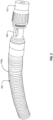
- FIG. 1 depicts a perspective view of the water directing device 100 for supplying water to the hand-held power tool.
- FIG. 2 depicts a perspective view of a water-supplying tube 102 of the water directing device 100.
- FIG. 3 depicts a perspective view of the water directing device 100 removably fastened to a hand-held power tool 300.
- FIG. 4 depicts a perspective view of a disassembled water-supplying tube 102 and water outlet parts.
- FIG. 5 depicts a perspective view of a dissembled water-supplying tube 102 and a pressure control unit 110.
- FIG. 6 depicts a perspective view of rotation of the pressure control unit 110 to adjust the pressure of water supplied onto a power tool 300.
- FIG. 7 depicts a perspective view of the water directing device 100 with a pulled back position of an outer coil 116.
- the water directing device 100 for supplying water comprises a water-supplying tube 102, a pressure control unit 110, and a connecting water line 106 which is configured with a flow valve 108.
- a connecting water line 106 which is configured with a flow valve 108.
- an adapter 118 such as a garden hose adapter, that can connect the connecting water line 106 to a water source, such as a garden hose.
- FIG. 2 a perspective view of the water-supplying tube 102 of the water directing device 100 is depicted.
- the water-supplying tube 102 of the water directing device 100 is fastened to a hand-held power tool 300, as depicted in FIG. 3 .
- the water-supplying tube 102 is fastened to the hand-held power tool 300 through one or more fasteners 302.
- the fasteners 302 can comprise, but are not limited to, ropes, Velcro ® straps, or any other means that can securely attach the water-supplying tube 102 to the hand-held power tool 300. As illustrated in FIG.
- a Velcro ® type of strap connects on one end of the water-supplying tube 102, surrounds the outer coil portion 116, wraps around the power tool 300, and connects back to itself.
- the water directing device 100 is easily attachable to and removable from any hand-held power tool 300, such as cutting saws, drills, and grinders, for stone, masonry, and tile work.
- the fasteners 302 removably attach and secure the water directing device 100 to the power tool 300, and the water directing device 100 remains attached to the power tool 300 while the power tool 300 is being used.
- the positions of the water-supplying tube 102 of the water directing device 100 can be adjusted relative to the power tool 300 and the substrate material 120, at the option of the user, to enable the pressure control unit 110 to be directed toward the power tool 300 and respective substrate material 120 being cut, drilled, and/or grinded by the power tool 300, such as the masonry drill power tool 300, illustrated in FIG. 3 , and such as the stone cutting saw power tool 300, illustrated in FIG. 6 .
- This adjustment allows the water to flow with sufficient pressure, and at an operator's desired angle, onto the power tool 300 and onto the respective substrate material 120 that is being cut or drilled or polished, while the power tool 300 is being operated.
- embodiments of the invention disclosed herein provide a controlled water attachment device 100 that provides an efficient and dependable solution for mitigating silica dusk particles at a point of cutting, grinding, and/or drilling, for nearly all cutting, grinding and drilling power tools 300 for stone, tile, and masonry work.
- a user or operator of a power tool 300 and the water directing device 100 can easily position the device 100 alongside the selected power tool 300, attach the device 100 to the power tool 300 with hook and loop fastening straps 302, and connect the adapter 118 of the connecting water line 106 to a water source such as a garden hose.
- the flow valve 108 of the water directing device 100 controls the rate of flow of water through the water connecting device 100, at the option of the user or operator.
- the water-supplying tube 102 comprises an inner tube 114 that is configured for supplying water to the power tool 300.
- the inner tube 114 is fabricated of a flexible aluminum material.
- the inner tube 114 is designed to flexibly adjust, at the action of the user to a desired position of the inner tube 114.
- the inner tube 114 is coated with black rubber. Accordingly, in a preferred embodiment, the rubber coated flexible aluminum inner tube 114 is positioned at the action of the user. This makes the inner tube 114 durable and resistant to abrasion. As can be appreciated from the disclosure herein, the rubber coated flexible aluminum inner tube 114 is held inside the outer coil 116.
- the outer coil 116 is wound around the inner tube 114 for securing the inner tube 114 tightly in position.
- the outer coil 116 helps facilitate positioning of the water directing device 100 at nearly any desired angle.
- the outer coil 116 is preferably made of a strong material such as copper.
- the outer coil 116 helps make the water directing device 100 durable while remaining flexible.
- the copper outer coil 116 is wounded around the rubber coated flexible aluminum inner tube 114 for securing the inner tube 114 tightly in place and for facilitating adjustment of the water directing device 100 into a variety of temporarily fixed positions, at the option of the user, while operating the power tool 300.
- the copper outer coil 116 comprises a first end 116a and a second end 116b.
- the inner tube 114 and the first end 116a of the copper outer coil 116 are connected to a nozzle 104 at an outlet 112 of the water-supplying tube 102. As illustrated in FIGS. 3 - 5 .
- the inner tube 114 and the second end 116b of the copper outer coil 116 are connected to a connecting water line 106.
- the water outlet parts include the outlet 112, the nozzle 104, and the pressure control unit 110, as illustrated in the exploded view in FIG. 4 in a disassembled position.
- FIG. 5 a perspective view of the disassembled water-supplying tube 102 and the pressure control unit 110 is depicted.
- the pressure control unit 110 is detachably attached to the nozzle 104 at the outlet 112 of the water-supplying tube 102 for adjusting the pressure of water supplied to the power tool 300, while the power tool 300 is being used.
- the pressure control unit 110 is easily removed from the water-supplying tube 102 for cleaning or replacement.
- the pressure control unit 110 is configured to adjust the pressure of water supplied to and directed at a point of cutting between the material substrate 120 and the hand-held power tool 300 by rotating the pressure control unit 110 clockwise or counter-clockwise, to achieve the desired water pressure while the power tool 300 is being used, as depicted in FIG. 6 .
- the pressure control unit 110 position can be adjusted manually for the operation of the power tool 300.
- the pressure control unit 110 position can be adjusted manually while the power tool 300 is being operated.
- the pressure control unit 110 preferably comprises a knob, a dial, or any other device that is used to adjust the pressure of water.
- the pressure control unit 110 is made of a material that is resistant to water and corrosion such as plastic, metal, and rubber.
- the pressure control unit 110 is connected to the water-supplying tube 102 through a snap-fit connection.
- a connecting water line 106 is connected to the water-supplying tube 102.
- the connecting water line 106 is configured for detachably connecting to the water-supplying tube 102.
- the connecting water line 106 is made of a material that is resistant to water and corrosion, such as vinyl, rubber, and plastic.
- the connecting water line 106 is configured with a flow valve 108 that allows the flow of water to be adjusted from a water-supplying unit through the water-supplying tube 102 and onto the power tool 300.
- the flow valve 108 is secured on the connecting water line 106 to the water-supplying tube 102 to control the speed and flow of the water feed.
- the connecting water line 106 is connected to the water-supplying tube 102, as illustrated in FIG. 7 .
- the universal water directing device 100 is removably fastened to any hand-held power tool 300 such as saws, drillers, and grinders for providing dust-free cutting, grinding, or polishing action, at the option of the operator of the power tool 300.
- the water directing device 100 is a compact and portable device that allows a user to easily carry the universal water directing device 100 from one place to another.
- the universal water directing device 100 enables a user to control the direction and speed of the water feed onto the power tool 300 and substrate material 120.
- the water directing device 100 requires less space than conventional devices and is less expensive to fabricate and produce.
Landscapes
- Engineering & Computer Science (AREA)
- Mechanical Engineering (AREA)
- Auxiliary Devices For Machine Tools (AREA)
- Grinding-Machine Dressing And Accessory Apparatuses (AREA)
- Perforating, Stamping-Out Or Severing By Means Other Than Cutting (AREA)
Abstract
A universal water directing device for supplying water to power tools is provided comprising an inner tube for supplying controlled water to a power tool and an outer coil wounded around the inner tube for securing the inner tube tightly in place. The universal water directing device comprises a pressure control unit detachably attached to a nozzle at an outlet of the watersupplying tube for adjusting the pressure of water supplied to the power tool while the power tool is being used. The device is removably fastened to a hand-held power tool and is configured to provide dust-free cutting, grinding, and/or polishing action. The water directing device is a portable device that can be attached to any hand-held power tool such as saws, drillers, and grinders thereof. The water directing device includes a flow valve to control the speed and flow rate of the water feed.
Description
- The present invention generally relates to the field of water cooling devices and, more particularly, to a universal attachable water directing device for supplying water to power tools while the tools are being used.
- In general, hand-held power tools (for example, stone grinding and cutting tools) often have a water supply arrangement for cooling the tools or the workpiece. The water supply arrangement is especially important for tools that produce more heat, such as cut-off machines. The water supply is typically controlled by an external valve that can be controlled before and after the tool is used. However, this can be inefficient, as it can lead to water being wasted before and after the actual cutting, or grinding, or polishing is done.
- One way to improve the water cooling system for power tools is to arrange the water supply control using a shut-off valve which is linked to a power tool's throttle trigger. This enables the water supply to be turned on only when the tool is being used. This arrangement can reduce water wastage and improve efficiency. The shut-off valve that is linked to the throttle trigger of the power tool is a mechanism that controls the flow of water to the tool. When the throttle trigger is not pulled, the shut-off valve is closed, and no water flows to the tool. When the throttle trigger is pulled, the shut-off valve opens, and water flows to the tool. This mechanism ensures that water is only supplied to the tool when it is being used, which can help to reduce water wastage and improve efficiency.
- However, there are some drawbacks to this approach. One is that the shut-off valve can be difficult to operate, especially when it is stiff or dirty. Additionally, if the valve is damaged, it can prevent the power tool from operating properly.
- Another approach to water supply control is to use a variable flow valve. This variable flow valve allows a user to adjust the amount of water that is supplied to the power tool. This can be useful for tasks that require different amounts of water, such as cutting different materials or working in different environments. The variable flow valve allows the user to adjust the amount of water to match the specific needs of the task. This can help to improve efficiency and prevent water wastage.
- However, the variable flow valves are typically more expensive and complex than simple shut-off valves, which can make them more difficult to maintain. The variable flow valves can be damaged if they are not properly maintained.
- While conventional devices for supplying water to hand-held power tools may be suitable for the particular purposes employed, they would not be as suitable for the purposes of the present invention as disclosed hereafter. None of such conventional devices for supplying water disclose the unique features and advantages of the present disclosure. The devices for supplying water to the hand-held power tools disclosed herein avoid many of the drawbacks of existing devices. Further, conventional devices are not compatible with all types of hand-held power tools.
- Accordingly, there is a need for a universal water directing device for supplying water to a hand-held power tool for dust-free cutting, or grinding, or polishing action.
- It is one prospect of the present invention to provide a portable water directing device for facilitating a user to easily carry the device from one place to another.
- Another object of the present invention is to provide a universal water directing device that can be removably attached to any hand-held power tool such as saws, drillers, and grinders thereof.
- Another object of the present invention is to provide a water directing device for supplying water to a hand-held power tool that facilitates a user to control the direction and speed of the water feed.
- As disclosed in this application, the inventor has discovered a universal water directing device for supplying water to a hand-held power tool that requires less space and is inexpensive.
- The following presents a simplified summary of the present disclosure in a simplified form as a prelude to the more detailed description that is presented herein.
- Therefore, by embodiments of the invention, there is provided a universal attachable water directing device for supplying water to a hand-held power tool.
- In a preferred embodiment, the water directing device for supplying water comprises a water-supplying tube, and a pressure control unit. A connecting water line is connected to the water directing device for supplying water.
- In another preferred embodiment, the water-supplying tube is fastened to a hand-held power tool. In specific, the water-supplying tube is removably fastened to the hand-held power tool through one or more fasteners. In specific, the fasteners can comprise, but are not limited to, ropes and Velcro® straps.
- In another preferred embodiment, the water-supplying tube comprises an inner tube that is configured for supplying controlled water to the power tool. Further, an outer coil is wounded around the inner tube for securing the inner tube tightly in place. In specific, the inner tube is fabricated of a flexible aluminum material. The inner tube is designed to flexibly adjust at the action of a user to a desired position of the inner tube. The inner tube is coated with black rubber. Further, the outer coil is a copper coil.
- In another preferred embodiment, the pressure control unit is detachably attached to a nozzle at an outlet of the water-supplying tube. The pressure control unit is configured to adjust the pressure of water supplied onto the power tool. The pressure control unit is rotated to adjust the pressure of water supplied to a point of cutting of the hand-held power tool.
- In another embodiment, a flow valve is secured on a connecting water line to the water-supplying tube to control the speed and flow of the water feed. The connecting water line is attached to the water-supplying tube. The connecting water line is configured for detachably connecting to the water-supplying tube.
- In a preferred embodiment, the water directing device comprises a water-supplying tube, a pressure control unit, and a flow valve. The water-supplying tube is removably fastened to a hand-held power tool. The water-supplying tube comprises a flexible aluminum inner tube and a copper outer coil. The flexible aluminum inner tube is configured for supplying controlled water to a power tool. The copper outer coil is wounded around the flexible aluminum inner tube for securing the inner tube tightly in place. In one embodiment, the copper outer coil comprises a first end and a second end. The first end is connected to a nozzle at an outlet of the water-supplying tube. The second end is connected to a connecting water line. The pressure control unit is detachably attached to the nozzle for adjusting the pressure of water supplied to the power tool, while the power tool is being used. The flow valve is secured on the connecting water line to the water-supplying tube to control the speed and flow of the water feed. The connecting water line is detachably connected to the water-supplying tube.
- Illustrative embodiments of the present invention are described herein with reference to the accompanying drawings, in which:
-
FIG. 1 depicts a perspective view of a universal water directing device for supplying water to a hand-held power tool, in accordance with embodiments of the invention; -
FIG. 2 depicts a perspective view of a water-supplying tube of the water directing device, in accordance with embodiments of the invention; -
FIG. 3 , depicts a perspective view of the water directing device fastened to a hand-held power tool, in accordance with embodiments of the invention; -
FIG. 4 depicts a perspective view of a disassembled water-supplying tube and water outlet parts, in accordance with some embodiments of the disclosure; -
FIG. 5 depicts a perspective view of a dissembled water-supplying tube and a pressure control unit, in accordance with some embodiments of the disclosure; -
FIG. 6 depicts a perspective view of rotation of the pressure control unit to adjust the pressure of water supplied onto a power tool, in accordance with some embodiments of the disclosure; and -
FIG. 7 depicts a perspective view of the water directing device with a pulled back position of an outer coil, in accordance with some embodiments of the disclosure. - For a further understanding of the nature and function of the embodiments, reference should be made to the following detailed description. Detailed descriptions of the embodiments are provided herein, as well as, the best mode of carrying out and employing the present invention. It will be readily appreciated that the embodiments are well adapted to carry out and obtain the ends and features mentioned as well as those inherent herein. It is to be understood, however, that the present invention may be embodied in various forms. Therefore, persons of ordinary skill in the art will realize that the following disclosure is illustrative only and not in any way limiting, as the specific details disclosed herein provide a basis for the claims and a representative basis for teaching to employ the present invention in virtually any appropriately detailed system, structure or manner. It should be understood that the devices, materials, methods, procedures, and techniques described herein are presently representative of various embodiments. Other embodiments of the disclosure will readily suggest themselves to such skilled persons having the benefit of this disclosure.
- Reference will now be made in detail to the present preferred embodiments of the invention, examples of which are illustrated in the accompanying drawings. Wherever possible, the same reference numerals are used in the drawings and the description to refer to the same or like parts.
- The present disclosure has been made with a view towards solving the problem with the prior art described above, and it is an object of the present invention to provide a universal removable water directing device for supplying water to a hand-held power tool.
- Referring initially to
FIGS. 1-7 , the basic constructional details and principles of operation of embodiments of awater directing device 100 for supplying water to the hand-held power tool are provided. - As illustrated,
FIG. 1 depicts a perspective view of thewater directing device 100 for supplying water to the hand-held power tool.FIG. 2 depicts a perspective view of a water-supplyingtube 102 of thewater directing device 100.FIG. 3 depicts a perspective view of thewater directing device 100 removably fastened to a hand-heldpower tool 300.FIG. 4 depicts a perspective view of a disassembled water-supplyingtube 102 and water outlet parts.FIG. 5 depicts a perspective view of a dissembled water-supplyingtube 102 and apressure control unit 110.FIG. 6 depicts a perspective view of rotation of thepressure control unit 110 to adjust the pressure of water supplied onto apower tool 300.FIG. 7 depicts a perspective view of thewater directing device 100 with a pulled back position of anouter coil 116. - Referring to
FIG. 1 , a perspective view of thewater directing device 100 for supplying water to a hand-heldpower tool 300 is depicted. Thewater directing device 100 for supplying water comprises a water-supplyingtube 102, apressure control unit 110, and a connectingwater line 106 which is configured with aflow valve 108. As illustrated inFIG. 1 , at an end of the connectingwater line 106 is anadapter 118, such as a garden hose adapter, that can connect the connectingwater line 106 to a water source, such as a garden hose. - Referring to
FIG. 2 , a perspective view of the water-supplyingtube 102 of thewater directing device 100 is depicted. The water-supplyingtube 102 of thewater directing device 100 is fastened to a hand-heldpower tool 300, as depicted inFIG. 3 . In specific, the water-supplyingtube 102 is fastened to the hand-heldpower tool 300 through one ormore fasteners 302. Thefasteners 302 can comprise, but are not limited to, ropes, Velcro® straps, or any other means that can securely attach the water-supplyingtube 102 to the hand-heldpower tool 300. As illustrated inFIG. 3 , for example, a Velcro® type of strap (i.e., hook and loop fastener strap) connects on one end of the water-supplyingtube 102, surrounds theouter coil portion 116, wraps around thepower tool 300, and connects back to itself. As can be seen and appreciated from the disclosure herein, thewater directing device 100 is easily attachable to and removable from any hand-heldpower tool 300, such as cutting saws, drills, and grinders, for stone, masonry, and tile work. Thefasteners 302 removably attach and secure thewater directing device 100 to thepower tool 300, and thewater directing device 100 remains attached to thepower tool 300 while thepower tool 300 is being used. - Through embodiments disclosed herein, the positions of the water-supplying
tube 102 of thewater directing device 100 can be adjusted relative to thepower tool 300 and thesubstrate material 120, at the option of the user, to enable thepressure control unit 110 to be directed toward thepower tool 300 andrespective substrate material 120 being cut, drilled, and/or grinded by thepower tool 300, such as the masonrydrill power tool 300, illustrated inFIG. 3 , and such as the stone cutting sawpower tool 300, illustrated inFIG. 6 . This adjustment allows the water to flow with sufficient pressure, and at an operator's desired angle, onto thepower tool 300 and onto therespective substrate material 120 that is being cut or drilled or polished, while thepower tool 300 is being operated. In such manner, embodiments of the invention disclosed herein provide a controlledwater attachment device 100 that provides an efficient and dependable solution for mitigating silica dusk particles at a point of cutting, grinding, and/or drilling, for nearly all cutting, grinding anddrilling power tools 300 for stone, tile, and masonry work. A user or operator of apower tool 300 and thewater directing device 100 can easily position thedevice 100 alongside the selectedpower tool 300, attach thedevice 100 to thepower tool 300 with hook and loop fastening straps 302, and connect theadapter 118 of the connectingwater line 106 to a water source such as a garden hose. Theflow valve 108 of thewater directing device 100 controls the rate of flow of water through thewater connecting device 100, at the option of the user or operator. - Referring to
FIG. 4 , a perspective view of a disassembled water-supplyingtube 102 and water outlet parts is depicted. The water-supplyingtube 102 comprises aninner tube 114 that is configured for supplying water to thepower tool 300. In a preferred embodiment, theinner tube 114 is fabricated of a flexible aluminum material. In a preferred embodiment, theinner tube 114 is designed to flexibly adjust, at the action of the user to a desired position of theinner tube 114. In a preferred embodiment, theinner tube 114 is coated with black rubber. Accordingly, in a preferred embodiment, the rubber coated flexible aluminuminner tube 114 is positioned at the action of the user. This makes theinner tube 114 durable and resistant to abrasion. As can be appreciated from the disclosure herein, the rubber coated flexible aluminuminner tube 114 is held inside theouter coil 116. - As exemplified in
FIG. 4 , theouter coil 116 is wound around theinner tube 114 for securing theinner tube 114 tightly in position. Theouter coil 116 helps facilitate positioning of thewater directing device 100 at nearly any desired angle. Theouter coil 116 is preferably made of a strong material such as copper. Theouter coil 116 helps make thewater directing device 100 durable while remaining flexible. In a preferred embodiment, the copperouter coil 116 is wounded around the rubber coated flexible aluminuminner tube 114 for securing theinner tube 114 tightly in place and for facilitating adjustment of thewater directing device 100 into a variety of temporarily fixed positions, at the option of the user, while operating thepower tool 300. - In a preferred embodiment, the copper
outer coil 116 comprises afirst end 116a and asecond end 116b. Theinner tube 114 and thefirst end 116a of the copperouter coil 116 are connected to anozzle 104 at anoutlet 112 of the water-supplyingtube 102. As illustrated inFIGS. 3 - 5 . Theinner tube 114 and thesecond end 116b of the copperouter coil 116 are connected to a connectingwater line 106. - The water outlet parts include the
outlet 112, thenozzle 104, and thepressure control unit 110, as illustrated in the exploded view inFIG. 4 in a disassembled position. - Referring to
FIG. 5 , a perspective view of the disassembled water-supplyingtube 102 and thepressure control unit 110 is depicted. Thepressure control unit 110 is detachably attached to thenozzle 104 at theoutlet 112 of the water-supplyingtube 102 for adjusting the pressure of water supplied to thepower tool 300, while thepower tool 300 is being used. Thepressure control unit 110 is easily removed from the water-supplyingtube 102 for cleaning or replacement. Thepressure control unit 110 is configured to adjust the pressure of water supplied to and directed at a point of cutting between thematerial substrate 120 and the hand-heldpower tool 300 by rotating thepressure control unit 110 clockwise or counter-clockwise, to achieve the desired water pressure while thepower tool 300 is being used, as depicted inFIG. 6 . - As illustrated herein, in one embodiment, the
pressure control unit 110 position can be adjusted manually for the operation of thepower tool 300. In one embodiment herein, thepressure control unit 110 position can be adjusted manually while thepower tool 300 is being operated. Thepressure control unit 110 preferably comprises a knob, a dial, or any other device that is used to adjust the pressure of water. Thepressure control unit 110 is made of a material that is resistant to water and corrosion such as plastic, metal, and rubber. In a preferred embodiment herein, thepressure control unit 110 is connected to the water-supplyingtube 102 through a snap-fit connection. - Referring to
FIG. 7 , a perspective view of thewater directing device 100 with a pulled back position of theouter coil 116, is depicted. A connectingwater line 106 is connected to the water-supplyingtube 102. The connectingwater line 106 is configured for detachably connecting to the water-supplyingtube 102. In specific, the connectingwater line 106 is made of a material that is resistant to water and corrosion, such as vinyl, rubber, and plastic. The connectingwater line 106 is configured with aflow valve 108 that allows the flow of water to be adjusted from a water-supplying unit through the water-supplyingtube 102 and onto thepower tool 300. In a preferred embodiment, theflow valve 108 is secured on the connectingwater line 106 to the water-supplyingtube 102 to control the speed and flow of the water feed. The connectingwater line 106 is connected to the water-supplyingtube 102, as illustrated inFIG. 7 . - The universal
water directing device 100 is removably fastened to any hand-heldpower tool 300 such as saws, drillers, and grinders for providing dust-free cutting, grinding, or polishing action, at the option of the operator of thepower tool 300. Thewater directing device 100 is a compact and portable device that allows a user to easily carry the universalwater directing device 100 from one place to another. The universalwater directing device 100 enables a user to control the direction and speed of the water feed onto thepower tool 300 andsubstrate material 120. Thewater directing device 100 requires less space than conventional devices and is less expensive to fabricate and produce. - Except as may be expressly otherwise indicated, the article "a" or "an" if and as used herein is not intended to limit, and should not be construed as limiting, the description or a claim to a single element to which the article refers. Rather, the article "a" or "an" if and as used herein is intended to cover one or more such elements, unless the text expressly indicates otherwise.
- This invention is susceptible to considerable variation within the spirit and scope of the appended claims.
Claims (9)
- A water directing device for supplying water to power tools, comprisinga water-supplying tube removably adapted to removably attach to a hand-held power tool, wherein the water-supplying tube comprisesan inner tube for supplying controlled water to the hand-held power tool and substrate material andan outer coil wounded around the inner tube tightly in place, wherein said outer coil is adapted to position the inner tube to direct a flow of water therethrough, at the option of the user of the hand-held power tool,and a pressure control unit detachably attached to a nozzle at an outlet of the water-supplying tube for adjusting the pressure of water supplied to the power tool while the power tool is being used.
- The water directing device according to claim 1, further comprising one or more fasteners, wherein the water-supplying tube is fastened to the hand-held power tool through one or more fasteners.
- The water directing device according to claim 1 or 2, characterised in that the inner tube is fabricated of a flexible aluminum material.
- The water directing device according to claim 1, 2 or 3, characterised in that the inner tube is designed to flexibly adjust at the action of the user to a desired position of the inner tube.
- The water directing device according to any one of claims 1 to 4, characterised in that the inner tube is coated with black rubber.
- The water directing device according to any one of claims 1 to 5, characterised in that the outer coil is a copper coil.
- The water directing device according to any one of claims 1 to 5, characterised in that the pressure control unit is adapted to rotate to adjust the pressure of water supplied to a point of cutting of the hand-held power tool.
- The water directing device according to any one of claims 1 to 7, characterised in that a flow valve is secured on a connecting water line to the water-supplying tube to control the speed and flow of the water feed, wherein the connecting water line is detachably connected to the water-supplying tube.
- A water directing device for supplying water to power tools, comprisinga water-supplying tube removably fastened to a hand-held power tool, wherein the water-supplying tube comprisesa flexible aluminum inner tube adapted to supply controlled water to a power tool anda copper outer coil wounded around the flexible aluminum inner tube for securing the inner tube tightly in place, wherein the copper outer coil comprisesa first end connected to a nozzle at an outlet of the water-supplying tube anda second end adapted to removably connect to a connecting water line,a pressure control unit detachably attached to the nozzle for adjusting the pressure of water supplied to the power tool while the power tool is in operation anda flow valve secured on the connecting water line to the water-supplying tube to control the speed and flow of the water feed, wherein the connecting water line is connected to the water-supplying tube.
Applications Claiming Priority (1)
| Application Number | Priority Date | Filing Date | Title |
|---|---|---|---|
| US18/241,779 US12528174B2 (en) | 2023-09-01 | 2023-09-01 | Universal attachable water directing device for power tools |
Publications (1)
| Publication Number | Publication Date |
|---|---|
| EP4516453A1 true EP4516453A1 (en) | 2025-03-05 |
Family
ID=89170088
Family Applications (1)
| Application Number | Title | Priority Date | Filing Date |
|---|---|---|---|
| EP24180462.4A Pending EP4516453A1 (en) | 2023-09-01 | 2024-06-06 | Universal attachable water directing device for power tools |
Country Status (4)
| Country | Link |
|---|---|
| US (1) | US12528174B2 (en) |
| EP (1) | EP4516453A1 (en) |
| AU (1) | AU2024203836A1 (en) |
| CA (1) | CA3253641A1 (en) |
Families Citing this family (1)
| Publication number | Priority date | Publication date | Assignee | Title |
|---|---|---|---|---|
| US12528174B2 (en) * | 2023-09-01 | 2026-01-20 | Hydro-Tail Llc | Universal attachable water directing device for power tools |
Citations (5)
| Publication number | Priority date | Publication date | Assignee | Title |
|---|---|---|---|---|
| US2235582A (en) * | 1939-12-28 | 1941-03-18 | Gorton George Machine Co | Discharge nozzle holder for machine tools |
| US20020045415A1 (en) * | 2000-06-22 | 2002-04-18 | Michael Bath | Dust-free masonry cutting tool |
| CN203221810U (en) * | 2013-05-03 | 2013-10-02 | 张辉 | Stone electric drill with water injector |
| CN103253053B (en) * | 2013-05-03 | 2015-12-16 | 张辉 | The multi-functional stone carving device of anti-dust |
| US20200086521A1 (en) * | 2018-04-02 | 2020-03-19 | Circsaw Technologies Llc | Water saw system for use in conjunction with a rolling plate assembly attachment for a portable sidewinder power saw |
Family Cites Families (81)
| Publication number | Priority date | Publication date | Assignee | Title |
|---|---|---|---|---|
| US1179575A (en) * | 1913-10-23 | 1916-04-18 | August Sundh | Flexible piping or hose. |
| US1651022A (en) * | 1920-09-28 | 1927-11-29 | Titeflex Metal Hose Co | Hose construction |
| US2121624A (en) * | 1936-09-16 | 1938-06-21 | Cowles Irving | Flexible conduit connection |
| US2166448A (en) * | 1937-11-19 | 1939-07-18 | Eastman Mfg Company | Hose protector |
| US2455113A (en) * | 1945-03-24 | 1948-11-30 | Coates Neligh Clair | Masonry saw |
| US2540203A (en) * | 1949-06-27 | 1951-02-06 | Sr George W Hatcher | Flexible connection |
| US2807502A (en) * | 1956-02-06 | 1957-09-24 | Tharp Homer Ray | Apparatus for killing roots in underground pipes |
| US2894536A (en) * | 1956-09-24 | 1959-07-14 | Emmanuel Kaye | Hoses |
| US3088756A (en) * | 1959-08-10 | 1963-05-07 | Aeroquip Corp | Fitting for hose spring guard |
| FR1301500A (en) * | 1960-08-19 | 1962-08-17 | Hydrol Chemical Company Ltd | Grinding machine |
| US3398609A (en) * | 1966-12-22 | 1968-08-27 | Thomas C Wilson Inc | Power tool |
| US3919026A (en) * | 1970-10-27 | 1975-11-11 | Kuraray Plastics Company Limit | Flexible hose manufacturing process |
| US3896783A (en) * | 1973-05-23 | 1975-07-29 | Artie L Manning | Cutting apparatus for cutting concrete material and the like |
| US3868195A (en) * | 1973-09-14 | 1975-02-25 | Cincinnati Milacron Heald | Coolant system for machine tool |
| US4517404A (en) * | 1983-02-02 | 1985-05-14 | Dayco Corporation | Multiple fluid conveying hose assembly and method of making same |
| US4570609A (en) * | 1984-10-05 | 1986-02-18 | Hogue John J | Water-cooled hub for flush-cut concrete saws |
| US4782591A (en) * | 1987-11-23 | 1988-11-08 | Devito Anthony | Saw blade cooling system |
| DE68902852T2 (en) * | 1988-03-03 | 1993-04-15 | Yoshino Seiki Kk | COOLANT SPRAYING SYSTEM FOR DRILLING DEVICES. |
| US5601893A (en) * | 1992-09-10 | 1997-02-11 | Elf Atochem S.A. | Flexible metal pipes with a shrinkable polymer sheath, a process for their fabrication, and their utilization as flexible tubular conduits |
| JPH07171930A (en) * | 1993-12-20 | 1995-07-11 | Bridgestone Corp | Rubber composite and production thereof |
| US5588469A (en) * | 1994-10-17 | 1996-12-31 | Marugo Rubber Industries, Ltd. | Hose for automotive fuel piping |
| AU695531B2 (en) * | 1994-10-18 | 1998-08-13 | Steven M. Utter | Portable mist cooling device |
| US5957765A (en) * | 1995-06-16 | 1999-09-28 | Kimbel; Erich | Hand-held machine tool |
| DE19545416A1 (en) * | 1995-12-06 | 1997-06-12 | Stihl Maschf Andreas | Nozzle for supplying liquid to a rotating tool |
| US5988226A (en) * | 1996-05-09 | 1999-11-23 | Senior Engineering Investments Ag | High pressure safety hose assembly and method of manufacturing |
| JPH10180874A (en) * | 1996-12-27 | 1998-07-07 | Canon Inc | Method for coating fluororesin tube and fixing member manufactured by the method |
| US5944263A (en) * | 1997-11-04 | 1999-08-31 | Everdry Marketing & Management, Inc. | Dust suppressing misting device for percussive tools |
| US6474896B1 (en) * | 1998-07-20 | 2002-11-05 | Delaine, Jr. Phillip M. | Oscillating aqua broom |
| IL125469A (en) * | 1998-07-23 | 2001-07-24 | Sherez Shaul | Hand held cutting tool |
| CH694817A8 (en) * | 1999-07-23 | 2005-10-14 | Frank Hohmann | High pressure hose. |
| US6425418B1 (en) * | 1999-10-27 | 2002-07-30 | Mitsubishi Cable Industries, Ltd. | Flexible tube and manufacturing method for the same |
| US6186136B1 (en) * | 1999-12-13 | 2001-02-13 | Blount, Inc. | Stretch reduction system for concrete cutting chain saw |
| US6591826B1 (en) * | 2000-06-06 | 2003-07-15 | Aktiebolaget Electrolux (Publ) | Device on a portable cutting or sawing machine |
| SE518103C2 (en) * | 2000-12-12 | 2002-08-27 | Electrolux Abp | Water pump at portable cutting machine |
| US6561287B2 (en) * | 2001-04-13 | 2003-05-13 | Deblasio Michael J. | Method and apparatus for sawing or drilling concrete |
| US6916236B2 (en) * | 2001-06-13 | 2005-07-12 | Terpstra Enterprises Pty Ltd. | Extraction apparatus |
| SE520013C2 (en) * | 2001-09-21 | 2003-05-06 | Electrolux Abp | Portable motor chain saw |
| US20030070306A1 (en) * | 2001-10-15 | 2003-04-17 | Mcdonald Jon Anthony | Apparatus for supporting a cutting saw about a substrate |
| US6779269B2 (en) * | 2001-11-13 | 2004-08-24 | Saint-Gobain Performance Plastics Corporation | Self-compensating hose coupling |
| US6948527B2 (en) * | 2001-11-24 | 2005-09-27 | Gary Dean Ragner | Pressure-actuated linearly retractable and extendible hose |
| US20040051303A1 (en) * | 2002-06-14 | 2004-03-18 | Alexander Lorenz | Multi-length flex connector |
| US7144312B2 (en) * | 2004-01-16 | 2006-12-05 | Glas-Weld Systems, Inc. | Scratch removal tool and system |
| US7063276B2 (en) * | 2004-03-23 | 2006-06-20 | Agri-Inject, Inc. | System for uniform dispersal of agricultural chemicals |
| DE102005044298B4 (en) * | 2004-10-29 | 2019-08-29 | Andreas Stihl Ag & Co. Kg | Protective hood of a hand-held cutting grinder |
| DE102005044297B4 (en) * | 2004-10-29 | 2019-08-22 | Andreas Stihl Ag & Co. Kg | Protective hood of a hand-held cutting grinder |
| DE102005002125A1 (en) * | 2005-01-17 | 2006-07-20 | Andreas Stihl Ag & Co. Kg | Device for water supply of hand-guided working tool, especially for supply to cutting disc of disc grinder, has opening cross-section of control valve provided with progressive characteristic curve depending upon adjustment travel |
| DE102005002126A1 (en) * | 2005-01-17 | 2006-07-20 | Andreas Stihl Ag & Co. Kg | Water supply of a hand-held implement |
| WO2006101423A1 (en) * | 2005-03-23 | 2006-09-28 | Husqvarna Ab | Improvements relating to a cutting or sawing machine |
| DE202005006371U1 (en) * | 2005-04-20 | 2006-08-31 | Dolmar Gmbh | Abrasive cutter |
| US8388418B2 (en) * | 2007-11-14 | 2013-03-05 | Robert Steven Greer | Thumb-operated detachable liquid polish dispenser for a hand-held surface finishing power tool |
| US8246423B2 (en) * | 2007-11-14 | 2012-08-21 | Robert Steven Greer | Thumb-operated detachable liquid polish dispenser for a hand-held surface finishing power tool |
| US20090130358A1 (en) * | 2007-11-16 | 2009-05-21 | Toyoda Gosei Co., Ltd. | Water hose and composition for hose |
| US8156966B2 (en) * | 2008-04-18 | 2012-04-17 | Senet Partners, Llc | Animal resistant tubing system |
| US9776296B2 (en) * | 2008-05-09 | 2017-10-03 | Milwaukee Electric Tool Corporation | Power tool dust collector |
| US7967391B1 (en) * | 2008-08-05 | 2011-06-28 | Dalley Brandon J | Saw and water combination system |
| WO2010071130A1 (en) * | 2008-12-17 | 2010-06-24 | カナフレックスコーポレーション株式会社 | Flexible, pressure-resistant and oil-resistant hose |
| US9909699B2 (en) * | 2011-03-17 | 2018-03-06 | Jay G. Bernhardt | Garden hose with spiral guard |
| US20120297948A1 (en) * | 2011-05-23 | 2012-11-29 | George Allen Kenton | Method to supply water to tile saw blade |
| DE202011050394U1 (en) * | 2011-06-08 | 2012-09-10 | Makita Corporation | Protective hood for a hand-held engine tool |
| DE202011050396U1 (en) * | 2011-06-08 | 2012-09-10 | Makita Corporation | Feeding device for spraying a tool of a hand-held engine tool and engine work tool |
| AU2013274951B2 (en) * | 2012-06-12 | 2015-07-16 | Husqvarna Ab | Electric cutting system |
| DE102012221273A1 (en) * | 2012-11-21 | 2014-05-22 | Hilti Aktiengesellschaft | Tool device with a spray device for dust binding |
| DE102012221275A1 (en) * | 2012-11-21 | 2014-05-22 | Hilti Aktiengesellschaft | Tool device with a spray device for dust binding |
| US9604297B2 (en) * | 2013-02-05 | 2017-03-28 | Husqvarna Ab | Liquid dispensing system |
| EP2965886B1 (en) * | 2014-06-18 | 2020-12-02 | Husqvarna AB | Tile or masonry saw assembly with improved blade wetting capability |
| USD787908S1 (en) * | 2016-02-01 | 2017-05-30 | Joseph Hebert | Electric portable wet saw |
| EP3412946A1 (en) * | 2017-06-09 | 2018-12-12 | Andreas Stihl AG & Co. KG | Method for actuating an electromagnetic valve and electromagnetic valve |
| US11833403B2 (en) * | 2018-03-15 | 2023-12-05 | Magic Sports, Llc | Bat swing training device |
| US12377504B2 (en) * | 2018-07-02 | 2025-08-05 | Husqvarna Ab | Protection arrangement for a power tool |
| JP7309740B2 (en) * | 2018-09-20 | 2023-07-18 | 富士フイルム株式会社 | Endoscope tubes and endoscopes |
| US11654597B1 (en) * | 2019-04-16 | 2023-05-23 | Jeff Leserra | Handheld hydraulic-powered concrete-cutting handsaw |
| EP4065316B1 (en) * | 2019-11-25 | 2025-05-14 | Husqvarna Ab | A hand-held electrically powered work tool |
| WO2021107827A1 (en) * | 2019-11-25 | 2021-06-03 | Husqvarna Ab | A hand-held electrically powered work tool |
| ES2834728B2 (en) * | 2019-12-17 | 2022-06-09 | Boada Germans Sa | COOLING DEVICE FOR DISC CUTTERS |
| EP4008475A1 (en) * | 2020-12-04 | 2022-06-08 | Hilti Aktiengesellschaft | Machine tool with a front handle and a regulating unit |
| US11828404B2 (en) * | 2021-08-09 | 2023-11-28 | PTubes, Inc. | Pipe for conveying fluids in HVACR systems |
| JP7762576B2 (en) * | 2022-01-07 | 2025-10-30 | 株式会社マキタ | electric work equipment |
| JP7745465B2 (en) * | 2022-01-07 | 2025-09-29 | 株式会社マキタ | Work equipment |
| US20240173811A1 (en) * | 2022-11-26 | 2024-05-30 | Charles Cooner | Hand mountable vacuum attachment |
| US20250067370A1 (en) * | 2023-08-21 | 2025-02-27 | Mark W. Gardner | Paired and interconnected counter-wound coiled hoses |
| US12528174B2 (en) * | 2023-09-01 | 2026-01-20 | Hydro-Tail Llc | Universal attachable water directing device for power tools |
-
2023
- 2023-09-01 US US18/241,779 patent/US12528174B2/en active Active
-
2024
- 2024-06-06 AU AU2024203836A patent/AU2024203836A1/en active Pending
- 2024-06-06 EP EP24180462.4A patent/EP4516453A1/en active Pending
- 2024-08-29 CA CA3253641A patent/CA3253641A1/en active Pending
Patent Citations (5)
| Publication number | Priority date | Publication date | Assignee | Title |
|---|---|---|---|---|
| US2235582A (en) * | 1939-12-28 | 1941-03-18 | Gorton George Machine Co | Discharge nozzle holder for machine tools |
| US20020045415A1 (en) * | 2000-06-22 | 2002-04-18 | Michael Bath | Dust-free masonry cutting tool |
| CN203221810U (en) * | 2013-05-03 | 2013-10-02 | 张辉 | Stone electric drill with water injector |
| CN103253053B (en) * | 2013-05-03 | 2015-12-16 | 张辉 | The multi-functional stone carving device of anti-dust |
| US20200086521A1 (en) * | 2018-04-02 | 2020-03-19 | Circsaw Technologies Llc | Water saw system for use in conjunction with a rolling plate assembly attachment for a portable sidewinder power saw |
Also Published As
| Publication number | Publication date |
|---|---|
| US12528174B2 (en) | 2026-01-20 |
| AU2024203836A1 (en) | 2025-03-20 |
| US20230405791A1 (en) | 2023-12-21 |
| CA3253641A1 (en) | 2025-06-03 |
Similar Documents
| Publication | Publication Date | Title |
|---|---|---|
| US5050291A (en) | Universal tool | |
| EP0214749B1 (en) | Extra-high pressure water injector | |
| US12528174B2 (en) | Universal attachable water directing device for power tools | |
| US7207114B2 (en) | Rotary knife with improved drive transmission | |
| US5947972A (en) | Irrigation pressurization system | |
| EP1625916B1 (en) | Integrated air tool and pressure regulator | |
| US6203415B1 (en) | Direct drive water-driven rotary tool | |
| US20080201877A1 (en) | Hand-held cleaning/polishing machine | |
| US3896783A (en) | Cutting apparatus for cutting concrete material and the like | |
| SE462901B (en) | DEVICE FOR GRINDING THE PIPE ON DRILL | |
| US9604297B2 (en) | Liquid dispensing system | |
| US4592170A (en) | Orbital abrading or polishing tool | |
| CN112272599B (en) | Movable tool machine with suction means and control method | |
| US6669543B2 (en) | Interchangeable handle grip assembly, conversion kit, and tools incorporating same | |
| US9227285B1 (en) | Removable reservoir for machine tool | |
| US6827637B2 (en) | Waterjet cutting system and method of operation | |
| CN102892537B (en) | Core drilling machine and handle assembly for the core drilling machine | |
| US5839948A (en) | Right angle sanders for wet sanding | |
| CN218364413U (en) | Portable combined wrench | |
| WO2008033973A1 (en) | Abrading device and system and method of using | |
| JPH0549863B2 (en) | ||
| US20120170989A1 (en) | Hand-held water drill | |
| CN112533730B (en) | Movable machine tools with movably supported working tools | |
| US2580842A (en) | Control valve for sandblast generators | |
| US20250162103A1 (en) | Water powered rotary tool |
Legal Events
| Date | Code | Title | Description |
|---|---|---|---|
| PUAI | Public reference made under article 153(3) epc to a published international application that has entered the european phase |
Free format text: ORIGINAL CODE: 0009012 |
|
| STAA | Information on the status of an ep patent application or granted ep patent |
Free format text: STATUS: THE APPLICATION HAS BEEN PUBLISHED |
|
| AK | Designated contracting states |
Kind code of ref document: A1 Designated state(s): AL AT BE BG CH CY CZ DE DK EE ES FI FR GB GR HR HU IE IS IT LI LT LU LV MC ME MK MT NL NO PL PT RO RS SE SI SK SM TR |
|
| STAA | Information on the status of an ep patent application or granted ep patent |
Free format text: STATUS: REQUEST FOR EXAMINATION WAS MADE |
|
| 17P | Request for examination filed |
Effective date: 20251124 |