EP4516438A1 - Thread cutting tap with textured neck surface - Google Patents
Thread cutting tap with textured neck surface Download PDFInfo
- Publication number
- EP4516438A1 EP4516438A1 EP23194842.3A EP23194842A EP4516438A1 EP 4516438 A1 EP4516438 A1 EP 4516438A1 EP 23194842 A EP23194842 A EP 23194842A EP 4516438 A1 EP4516438 A1 EP 4516438A1
- Authority
- EP
- European Patent Office
- Prior art keywords
- thread cutting
- protrusion
- neck portion
- cutting tap
- neck
- Prior art date
- Legal status (The legal status is an assumption and is not a legal conclusion. Google has not performed a legal analysis and makes no representation as to the accuracy of the status listed.)
- Granted
Links
Images


Classifications
-
- B—PERFORMING OPERATIONS; TRANSPORTING
- B23—MACHINE TOOLS; METAL-WORKING NOT OTHERWISE PROVIDED FOR
- B23G—THREAD CUTTING; WORKING OF SCREWS, BOLT HEADS, OR NUTS, IN CONJUNCTION THEREWITH
- B23G5/00—Thread-cutting tools; Die-heads
- B23G5/02—Thread-cutting tools; Die-heads without means for adjustment
- B23G5/06—Taps
-
- B—PERFORMING OPERATIONS; TRANSPORTING
- B23—MACHINE TOOLS; METAL-WORKING NOT OTHERWISE PROVIDED FOR
- B23P—METAL-WORKING NOT OTHERWISE PROVIDED FOR; COMBINED OPERATIONS; UNIVERSAL MACHINE TOOLS
- B23P15/00—Making specific metal objects by operations not covered by a single other subclass or a group in this subclass
- B23P15/28—Making specific metal objects by operations not covered by a single other subclass or a group in this subclass cutting tools
- B23P15/48—Making specific metal objects by operations not covered by a single other subclass or a group in this subclass cutting tools threading tools
- B23P15/52—Making specific metal objects by operations not covered by a single other subclass or a group in this subclass cutting tools threading tools taps
-
- B—PERFORMING OPERATIONS; TRANSPORTING
- B23—MACHINE TOOLS; METAL-WORKING NOT OTHERWISE PROVIDED FOR
- B23G—THREAD CUTTING; WORKING OF SCREWS, BOLT HEADS, OR NUTS, IN CONJUNCTION THEREWITH
- B23G2200/00—Details of threading tools
- B23G2200/26—Coatings of tools
-
- B—PERFORMING OPERATIONS; TRANSPORTING
- B23—MACHINE TOOLS; METAL-WORKING NOT OTHERWISE PROVIDED FOR
- B23G—THREAD CUTTING; WORKING OF SCREWS, BOLT HEADS, OR NUTS, IN CONJUNCTION THEREWITH
- B23G2200/00—Details of threading tools
- B23G2200/48—Spiral grooves, i.e. spiral flutes
-
- B—PERFORMING OPERATIONS; TRANSPORTING
- B23—MACHINE TOOLS; METAL-WORKING NOT OTHERWISE PROVIDED FOR
- B23G—THREAD CUTTING; WORKING OF SCREWS, BOLT HEADS, OR NUTS, IN CONJUNCTION THEREWITH
- B23G2240/00—Details of equipment for threading other than threading tools, details of the threading process
- B23G2240/08—Evacuation of chips or fines
Definitions
- the invention relates to metal cutting, and in particular to thread cutting taps for cutting internal threads in holes in metal workpieces.
- the invention also relates to a method for manufacturing such thread cutting taps.
- a thread cutting tap may be used for machining an internal thread in a hole in a workpiece.
- Thread cutting taps sometimes have a "neck" with reduced diameter, located between the shank and the threaded front portion of the tap.
- Such thread cutting taps often include chip flutes extending along the threaded front portion and into the neck portion. The flutes may be helical in order to improve evacuation of chips from the threaded hole.
- the chips produced may easily entangle around the tap, causing so called "bird nests" of chips around the neck of the tap. If using straight-fluted taps, the problem of bird nesting can be reduced, but on the other hand such taps may not provide sufficient chip evacuation.
- the invention relates to thread cutting tap that comprises a front end, a rear end, a longitudinal axis extending from the front end to the rear end, a thread cutting portion extending rearward along the longitudinal axis from the front end, and a shank extending forward along the longitudinal axis from the rear end.
- the thread cutting tap further comprises a neck portion located between the thread cutting portion and the shank, wherein the neck portion comprises a plurality of lands separated from each other by a corresponding number of flutes. At least a part of at least one of the lands in the neck portion has a textured surface comprising a plurality of protrusions, each protrusion extending radially outwards from a neck bottom to a protrusion peak.
- protrusions may improve chip control and help mitigating entangling of chips around the neck portion that may otherwise occur when machining materials that produces long chips, such as low alloy steel, stainless steel or aluminum. Accordingly, the protrusions are arranged to break or deflect chips formed when using the thread cutting tap to cut a thread in a hole in a workpiece.
- Flutes formed in the thread cutting portion may continue into the neck portion, and extend axially along at least a part thereof, but not necessarily along the full axial length of the neck portion.
- the neck portion may include a region near the shank that is devoid of flutes.
- the textured surface may be present also on such fluteless regions of the neck portion.
- the neck portion is formed at a diameter smaller than the diameter of the thread cutting portion. More specifically, the neck portion has a diameter that is smaller than the cutting diameter not only at the crest but also at the root of each thread cutting tooth, such that no part of the neck portion engages the surface of the threaded hole during machining. Hence, the intersections between the lands and the flutes in the neck portion do not form cutting edges.
- the purpose of the neck portion is to facilitate thread cutting deep down in a hole with maintained chip evacuation.
- the flutes in the neck portion are usually continuations of the flutes formed in the thread cutting portion, such that the cutting lands, including cutting teeth, in the thread cutting portion smoothly transitions into the non-cutting lands in the neck portion.
- the neck portion should have a neck diameter that is small enough to not interfere in the cutting process, but large enough to maintain a sufficient strength and stability of the thread cutting tap.
- the neck portion may have a neck diameter that is in a range of 0.6-0.8 times the maximum cutting diameter of the thread cutting portion.
- the protrusions in the neck portion may be formed by subtractive machining, e.g. cutting, or by a cold forming process, such as knurling.
- a cold forming process will, as a result of forming depressions in the surface, result in protrusions between the depressions that protrude not only with respect to the bottoms of the depressions but also, to some extent, with respect to the original surface.
- the protrusions do not necessarily extend radially beyond the original (not yet textured) surface, but may constitute protrusions only with respect to the adjacent depressions formed in the surface, as would be the case if forming depressions by subtractive manufacturing (cutting).
- the protrusions may be considered as the portions located between depressions formed in the surface, irrespective of how these depressions were formed. However, it is also envisaged that the protrusions are formed in a different way not involving the formation of depressions in the surface.
- the protrusions protrude radially outwards, meaning that the protrusion may extend along a protrusion extension axis that has at least some component in a radial direction with respect to the longitudinal axis of the thread cutting tap.
- such protrusion extension axis is perpendicular to and intersects the longitudinal axis of the thread cutting tap.
- a protrusion extension axis of each protrusion may be directed entirely in a radial direction.
- the neck bottom should be understood as the imaginary surface on which the points on the lands of the neck portion closest to the longitudinal axis are located (i.e. points in the "valleys" between the protrusions.
- the neck bottom would constitute a circular cylindrical surface that includes all such valley points.
- the protrusion peak of each protrusion should be understood as the point or surface segment of the protrusion that is located farthest from the longitudinal axis, thus defining the (maximum) diameter of the neck portion.
- the neck portion may adjoin the thread cutting portion, either directly or via a transition region (e.g. a region in which the diameter smoothly changes from a thread cutting diameter to a reduced diameter of the neck portion).
- a transition region e.g. a region in which the diameter smoothly changes from a thread cutting diameter to a reduced diameter of the neck portion.
- the axial length of the neck portion in relation to the axial length of the thread cutting portion may vary for different types of thread cutting taps.
- the axial length of the neck portion may be greater than the axial length of the thread cutting portion.
- the axial length of the neck portion may be at least twice the axial length of the cutting portion.
- the thread cutting tap may be made from a wear resistant material, such as cemented carbide or high speed steel.
- the textured surface covers a major part of each land in the neck portion.
- the chip control is further increased compared to a thread cutting tap wherein only a small part of the lands in the neck portion is textured.
- the textured surface may for example completely cover each land in the neck portion.
- each protrusion comprises a first surface and a second surface, adjoining each other at a first edge extending from the neck bottom to the protrusion peak.
- Such edge of the protrusion may increase the chip control by improving the chip breaking.
- the edge may act as a knife breaking the chips into smaller pieces.
- each protrusion face forward, and each protrusion comprises also a third surface and a fourth surface each facing rearward.
- the first surface adjoins the third surface at a second edge extending from the neck bottom to the protrusion peak, and the second surface adjoins the fourth surface at a third edge extending from the neck bottom to the protrusion peak.
- a surface "facing forward” in this context means that a normal to the surface has a component in the forward direction (a direction along the longitudinal axis towards the front end of the thread cutting tap) but not in the rearward direction (a direction along the longitudinal axis towards the rear end of the thread cutting tap).
- each of the first and second surfaces may have respective normals that, if broken into a longitudinal component, a radial component and a tangential component, has a longitudinal component in the forward direction.
- a surface “facing rearward” should be understood as a surface of which a normal has a component in the rearward direction.
- the first surface forms an internal angle of 30°- 90° to the second surface.
- Protrusions having such configuration may be easy to manufacture and will provide sufficiently sharp edges for obtaining a good chip dividing effect.
- each protrusion may have the shape of a truncated pyramid having a square or rhombic bottom base at the neck bottom and a top base at the protrusion peak and wherein the first, second, third and fourth surfaces make up the lateral faces of the truncated pyramid, and wherein the protrusion extends along a protrusion extension axis from the centroid of the bottom base to the centroid of the top base.
- a normal to the first surface or the second surface, when projected on a longitudinal plane perpendicular to a radial line through the protrusion, may form an angle of 30°-75° to the longitudinal axis of the thread cutting tap, for example 45° or 60°.
- the first and the second surfaces may be symmetrically arranged with respect to the longitudinal axis, i.e. such that the first edge, when projected on the longitudinal plane, extends in parallel with the longitudinal axis of the thread cutting tap.
- one of the diagonals of the bottom base may be parallel to the longitudinal axis of the thread cutting tap.
- each protrusion has a protrusion height, corresponding to the minimum distance between the neck bottom to the protrusion peak.
- the protrusion height is within a range of 0.05-0.35 times the diameter of the neck portion. Accordingly, different protrusion heights may be used for different tool diameters.
- the protrusions shall be sufficiently large for effectively breaking the chips.
- a larger thread cutting tap produces larger chips that requires larger protrusions for effective chip control.
- the protrusion height may be as small as 0.75 mm.
- the protrusion height may be 3 mm or even more.
- a protrusion height in the range of 1-3 mm may be suitable for many thread cutting taps.
- the diameter of the neck portion should be understood as the diameter at which the protrusion peaks are located. This may correspond to the diameter of the unmodified neck, i.e. the neck before protrusions are formed, but the diameter may also be somewhat greater than the diameter of the original neck, in particular if the protrusions are formed by a cold forming process, such a knurling. Nevertheless, the neck diameter will still be smaller than the cutting diameter of the thread cutting portion of the tap.
- all, or substantially all, of the protrusions have the same size and shape and are distributed over the textured surface in a pattern. Thereby, a uniform chip breaking effect is obtained all over the textured surface.
- the pattern may be defined by a recurrence of the protrusions at a certain pitch. According to some embodiments, the pitch is within a range of 0.1-0.5 times the diameter of the neck portion.
- substantially all of the protrusions in this case should be understood as all protrusions that are not affected by other features on the neck, such as the flutes.
- some protrusions adjacent the flutes, or adjacent axial front- or rear ends of the neck may have somewhat different and possibly irregular shapes, for example due to that parts of the protrusions may have been removed when grinding the flutes.
- the pitch is measured between consecutive protrusion peaks along the textured surface. If the protrusions are applied using a knurling tool, the pitch corresponds to the pitch of the knurling tool, i.e. the distance between teeth of the knurling tool in a direction perpendicular to the extension of such teeth.
- the protrusion height of each protrusion is 0.5 - 0.8 times the pitch.
- a pattern of protrusions having such relationship between pitch and protrusion height may be particularly effective for achieving improved chip control.
- the pattern of the textured surface is formed by two sets of trenches, the two sets extending along the neck portion helicoidally, but in different directions, around the longitudinal axis of the thread cutting tap, such that a trench of the first set intersects a trench of the second set at an angle of 30°-120°, and wherein the regions between the respective trenches form the protrusions.
- Such configuration may result in protrusions having the shape of truncated pyramids.
- a trench of the first set may intersect a trench of the second set at an angle of 60°, 90° or 120°, in particular if the trenches are made by a conventional knurling tool that often has knurling teeth that extend at an angle of 30°, 45° or 60° to a rotational axis thereof.
- a trench of the first set intersects a trench of the second set at some other angle, including an angle smaller than 60°.
- the textured surface is a knurled surface.
- the protrusions may be formed by a knurling process in which a knurling tool engages the neck portion of the thread cutting tap in order to form the protrusions.
- a knurling tool using two wheels, one with left-hand teeth and one with right-hand teeth may be used for creating two sets of intersecting trenches as referred to above, resulting in a pattern of protrusions shaped as truncated pyramids.
- Such knurls are sometimes referred to as "diamond knurls" since the rhombus- or square shaped bases of the pyramids together form a diamond-pattern.
- the teeth on such knurling wheels may for example be formed at an angle of 30° or 45° to the rotation axis of the wheel, resulting in protrusions having a shape of pyramids with rhombic bases (with the major diagonal of each rhombus directed in parallel with the longitudinal axis of the thread cutting tap) or protrusions having a shape of pyramids with square bases, respectively.
- the protrusions are formed by other means, for example by milling or laser machining.
- the invention relates to a method for manufacturing a thread cutting tap according to any of the embodiments described herein wherein the textured surface is a knurled surface, the method comprising the steps of:
- the method may include further steps, performed prior to, in between, or after the steps defined above.
- the method may comprise forming a thread cutting portion including a plurality of thread cutting teeth in the blank.
- Other steps that may also be carried out when manufacturing the thread cutting tap is sintering (if the thread cutting tap is made of carbide) and coating.
- the thread cutting tap 1 comprises a front end 2 and a rear end 3.
- a longitudinal axis L extends longitudinally through the thread cutting tap from the front end 2 to the rear end 3.
- a thread cutting portion 4 extends rearward from the front end 2.
- the thread cutting portion 4 includes cutting lands 24 including a plurality of thread cutting teeth 25 arranged to cut internal threads in a hole when the thread cutting tap is fed into the hole during rotational movement of the tap around the longitudinal axis L.
- the thread cutting portion 4 further includes flutes 8 separating the cutting lands.
- the flutes 8 extend with respect to the longitudinal axis at a helix angle ⁇ (illustrated in fig. 2 ).
- the thread cutting tap comprises a shank 5 extending forward from the rear end 3.
- the shank 5 is adapted to be arranged to a tool holder (not shown), and for example coupled to a machine tool configured to perform a thread cutting operation.
- a neck portion 6 is located between the shank 5 and the thread cutting portion 4.
- the neck portion 6 has a smaller diameter than the thread cutting portion, and is not meant to engage the workpiece during a thread cutting operation.
- the flutes 8 extends from the thread cutting portion 4 into the neck portion 6 in order to facilitate chip evacuation. Lands 7 are thus provided in the neck portion 6 between the flutes 8. In the illustrated embodiment, the flutes 8 do not extend over the full length of the neck portion 6, but only about 75% of the length.
- the axial length LN of the neck portion 6 is greater than the axial length LC of the thread cutting portion 4.
- the lands 7 in the neck portion has a textured surface and comprises a plurality of protrusions 9.
- the protrusions 9 completely cover all of the lands 7 in the neck portion 6, and also the part of the neck portion 6 extending rearward beyond the location where the flutes 8 end.
- Each protrusion 9 extend radially outwards from the neck portion along a protrusion extension axis A (illustrated in Fig. 4 ), which in this case is perpendicular to and intersects the longitudinal axis L of the thread cutting tap.
- Each protrusion 9 extends from a neck bottom 10 to a protrusion peak 11.
- the diameter ⁇ of the neck portion is the maximum diameter, i.e. the diameter at which the protrusion peaks 11 of the protrusions 9 are located.
- the protrusions 9 are applied to the neck portion 6 using a knurling process, wherein a knurling tool forms right-hand trenches 20 and left-hand trenches 21 in the surface of the neck portion, schematically illustrated in dashed lines in the enlarged view in fig. 2 .
- Protrusions are thus formed in a pattern where the recurrence of the protrusions 11 corresponds to a pitch P, illustrated in the enlarged view of Fig. 2 .
- the resulting protrusions 9 have the shape of truncated pyramids, as best seen in Fig. 3 , showing one of the protrusions in a plan view of the neck portion from a radial direction, and in Fig. 4 , showing a section perpendicular to the longitudinal axis L.
- the section of one of the protrusions is shown in further detail.
- the protrusion has a height H, corresponding to the shortest distance between the neck bottom and the protrusion peak, i.e. in this case the distance from the neck bottom 10 to the protrusion peak 11 when measured along the protrusion extension axis A.
- the trenches are illustrated as having a helix angle ⁇ of about 23°, resulting in an angle 2 ⁇ formed between a right-hand trench 20 and a left-hand trench 21 of about 46°.
- a M8 thread cutting tap with a neck diameter ⁇ of 6 mm was provided with protrusions using a knurling process resulting in a trench helix angle ⁇ of 30°, a pitch P of 1.5 mm, and a protrusion height H of 1.2 mm.
- Each pyramid shaped protrusion includes four lateral surfaces of which a first surface 12 and a second surface 13 face forward, whereas a third surface 15 and a fourth surface 16 face rearward.
- all four lateral surface 12, 13, 15, 16 are planar surfaces.
- the lateral surfaces of a protrusion 9 may be slightly curved, e.g. convex.
- a normal N to the first surface or the second surface when projected on a longitudinal plane perpendicular to a radial line through the protrusion (corresponding to the protrusion extension axis A in this case), forms an angle ⁇ to the longitudinal axis L of the tap, which in the illustrated embodiment is about 67° (and would be 60° for the exemplary embodiment referred to above where the helix angle ⁇ of the trenches is 30°).
- a first edge 14 is formed at the intersection between the first surface 12 and the second surface 13.
- a second edge 17 is formed at the intersection between the first surface 12 and the third surface 15
- a third edge 18 is formed at the intersection between the second surface 13 and the fourth surface 16
- a fourth edge 19 is formed at the intersection between the third surface 15 and the fourth surface 16.
- the second edge 17 forms an internal angle ⁇ to the third edge 18, which in this case corresponds to the angle between the first surface 12 and the second surface 13, as well as the angle between the third surface 15 and the fourth surface 16.
- the internal angle ⁇ is about 50°.
- a blank is provided that includes a front end, a rear end and a peripheral surface, wherein the peripheral surface extends from the front end to the rear end around a central longitudinal axis.
- the blank may be a circular cylindrical body, for example made of high-speed steel.
- a neck portion is formed in the blank, the neck portion having a smaller diameter than a portion of the blank in front thereof. This is for example achieved by turning or grinding the blank. Thereby, the portion in front of the neck portion, that will include thread cutting teeth, will be located at a greater diameter than the neck portion.
- a knurling process is applied to the neck portion, such that at least a part of the surface of the neck portion becomes a knurled surface.
- the whole neck portion is knurled.
- the knurling may be achieved using a knurling tool, for example arranged on a lathe.
- the knurling tool may include two wheels or rollers with teeth extending diagonally (left-handed for one roller and right-handed for the other roller) across the surface of the rollers.
- Such knurling tool is caused to engage the blank while the blank is rotated, such that one roller presses against the blank from one side and the other roller from the other side. The rollers will thereby rotate in contact with the rotating blank and form diamond shaped protrusions in the surface of the neck portion.
- step 504 a plurality of lands are formed in the neck portion, by forming flutes separating the lands.
- the flutes for example formed by grinding, are preferably formed also in the thread cutting portion in the same operation. As a consequence of forming the flutes, some parts of the knurled surface in the neck portion are removed, but the knurled surface will remain in other regions, including the lands between the flutes.
Landscapes
- Engineering & Computer Science (AREA)
- Mechanical Engineering (AREA)
- Cutting Tools, Boring Holders, And Turrets (AREA)
- Milling Processes (AREA)
Abstract
Description
- The invention relates to metal cutting, and in particular to thread cutting taps for cutting internal threads in holes in metal workpieces. The invention also relates to a method for manufacturing such thread cutting taps.
- In the field of metal cutting, a thread cutting tap may be used for machining an internal thread in a hole in a workpiece. Thread cutting taps sometimes have a "neck" with reduced diameter, located between the shank and the threaded front portion of the tap. Such thread cutting taps often include chip flutes extending along the threaded front portion and into the neck portion. The flutes may be helical in order to improve evacuation of chips from the threaded hole. In some materials, such as low alloy steels or aluminum, the chips produced may easily entangle around the tap, causing so called "bird nests" of chips around the neck of the tap. If using straight-fluted taps, the problem of bird nesting can be reduced, but on the other hand such taps may not provide sufficient chip evacuation.
- Hence, there is a need for thread cutting taps with improved chip control.
- It is an object of the present invention to mitigate the shortcomings of the prior art and to provide a thread cutting tap with improved chip control and a method for manufacturing such thread cutting tap.
- Thus, according to a first aspect, the invention relates to thread cutting tap that comprises a front end, a rear end, a longitudinal axis extending from the front end to the rear end, a thread cutting portion extending rearward along the longitudinal axis from the front end, and a shank extending forward along the longitudinal axis from the rear end. The thread cutting tap further comprises a neck portion located between the thread cutting portion and the shank, wherein the neck portion comprises a plurality of lands separated from each other by a corresponding number of flutes. At least a part of at least one of the lands in the neck portion has a textured surface comprising a plurality of protrusions, each protrusion extending radially outwards from a neck bottom to a protrusion peak.
- Such protrusions may improve chip control and help mitigating entangling of chips around the neck portion that may otherwise occur when machining materials that produces long chips, such as low alloy steel, stainless steel or aluminum. Accordingly, the protrusions are arranged to break or deflect chips formed when using the thread cutting tap to cut a thread in a hole in a workpiece.
- Flutes formed in the thread cutting portion may continue into the neck portion, and extend axially along at least a part thereof, but not necessarily along the full axial length of the neck portion. In other words, the neck portion may include a region near the shank that is devoid of flutes. The textured surface may be present also on such fluteless regions of the neck portion.
- The flutes may be helical such that the flutes and the lands extend axially along the neck portion (and the thread cutting portion) following a curved helical path around the longitudinal axis (i.e. the rotation axis of the tap), with this path deviating from the longitudinal axis by a helix angle. As an example, such helix angle may be 30° or above, e.g. 45° or even higher. The problem of bird nesting of chips in the neck portion is more common for thread cutting taps having large helix angle, and the present invention may therefore be most beneficial in view of such thread cutting taps. However, it is also envisaged that the flutes have a smaller helix angle, or even flutes that are straight, i.e. aligned generally in parallel to the longitudinal axis of the tap.
- The neck portion is formed at a diameter smaller than the diameter of the thread cutting portion. More specifically, the neck portion has a diameter that is smaller than the cutting diameter not only at the crest but also at the root of each thread cutting tooth, such that no part of the neck portion engages the surface of the threaded hole during machining. Hence, the intersections between the lands and the flutes in the neck portion do not form cutting edges. The purpose of the neck portion is to facilitate thread cutting deep down in a hole with maintained chip evacuation. As already mentioned, the flutes in the neck portion are usually continuations of the flutes formed in the thread cutting portion, such that the cutting lands, including cutting teeth, in the thread cutting portion smoothly transitions into the non-cutting lands in the neck portion.
- The neck portion should have a neck diameter that is small enough to not interfere in the cutting process, but large enough to maintain a sufficient strength and stability of the thread cutting tap. For example, the neck portion may have a neck diameter that is in a range of 0.6-0.8 times the maximum cutting diameter of the thread cutting portion.
- The protrusions in the neck portion may be formed by subtractive machining, e.g. cutting, or by a cold forming process, such as knurling. A cold forming process will, as a result of forming depressions in the surface, result in protrusions between the depressions that protrude not only with respect to the bottoms of the depressions but also, to some extent, with respect to the original surface. However, the protrusions do not necessarily extend radially beyond the original (not yet textured) surface, but may constitute protrusions only with respect to the adjacent depressions formed in the surface, as would be the case if forming depressions by subtractive manufacturing (cutting). Thus, according to some embodiments, the protrusions may be considered as the portions located between depressions formed in the surface, irrespective of how these depressions were formed. However, it is also envisaged that the protrusions are formed in a different way not involving the formation of depressions in the surface.
- The protrusions protrude radially outwards, meaning that the protrusion may extend along a protrusion extension axis that has at least some component in a radial direction with respect to the longitudinal axis of the thread cutting tap. According to some embodiments, for each protrusion, such protrusion extension axis is perpendicular to and intersects the longitudinal axis of the thread cutting tap. In other words, a protrusion extension axis of each protrusion may be directed entirely in a radial direction.
- The "neck bottom" should be understood as the imaginary surface on which the points on the lands of the neck portion closest to the longitudinal axis are located (i.e. points in the "valleys" between the protrusions. For a cylindrical neck portion, the neck bottom would constitute a circular cylindrical surface that includes all such valley points. The protrusion peak of each protrusion should be understood as the point or surface segment of the protrusion that is located farthest from the longitudinal axis, thus defining the (maximum) diameter of the neck portion.
- The neck portion may adjoin the thread cutting portion, either directly or via a transition region (e.g. a region in which the diameter smoothly changes from a thread cutting diameter to a reduced diameter of the neck portion).
- The axial length of the neck portion in relation to the axial length of the thread cutting portion may vary for different types of thread cutting taps. The axial length of the neck portion may be greater than the axial length of the thread cutting portion. For example, the axial length of the neck portion may be at least twice the axial length of the cutting portion.
- The thread cutting tap may be made from a wear resistant material, such as cemented carbide or high speed steel.
- According to some embodiments, the textured surface covers a major part of each land in the neck portion. Thereby, the chip control is further increased compared to a thread cutting tap wherein only a small part of the lands in the neck portion is textured. The textured surface may for example completely cover each land in the neck portion.
- According to some embodiments, each protrusion comprises a first surface and a second surface, adjoining each other at a first edge extending from the neck bottom to the protrusion peak. Such edge of the protrusion may increase the chip control by improving the chip breaking. Thus, the edge may act as a knife breaking the chips into smaller pieces.
- According to some embodiments, the first surface and the second surface face forward, and each protrusion comprises also a third surface and a fourth surface each facing rearward. The first surface adjoins the third surface at a second edge extending from the neck bottom to the protrusion peak, and the second surface adjoins the fourth surface at a third edge extending from the neck bottom to the protrusion peak. Thereby, each protrusion includes a plurality of edges that help breaking the chips.
- A surface "facing forward" in this context means that a normal to the surface has a component in the forward direction (a direction along the longitudinal axis towards the front end of the thread cutting tap) but not in the rearward direction (a direction along the longitudinal axis towards the rear end of the thread cutting tap). As an example, each of the first and second surfaces may have respective normals that, if broken into a longitudinal component, a radial component and a tangential component, has a longitudinal component in the forward direction. Correspondingly, a surface "facing rearward" should be understood as a surface of which a normal has a component in the rearward direction.
- According to some embodiments, the first surface forms an internal angle of 30°- 90° to the second surface. Protrusions having such configuration may be easy to manufacture and will provide sufficiently sharp edges for obtaining a good chip dividing effect.
- According to some embodiments, each protrusion may have the shape of a truncated pyramid having a square or rhombic bottom base at the neck bottom and a top base at the protrusion peak and wherein the first, second, third and fourth surfaces make up the lateral faces of the truncated pyramid, and wherein the protrusion extends along a protrusion extension axis from the centroid of the bottom base to the centroid of the top base.
- For each protrusion, a normal to the first surface or the second surface, when projected on a longitudinal plane perpendicular to a radial line through the protrusion, may form an angle of 30°-75° to the longitudinal axis of the thread cutting tap, for example 45° or 60°. The first and the second surfaces may be symmetrically arranged with respect to the longitudinal axis, i.e. such that the first edge, when projected on the longitudinal plane, extends in parallel with the longitudinal axis of the thread cutting tap. In other words, for a protrusion having the shape of a truncated pyramid, one of the diagonals of the bottom base may be parallel to the longitudinal axis of the thread cutting tap.
- Each protrusion has a protrusion height, corresponding to the minimum distance between the neck bottom to the protrusion peak. According to some embodiments, the protrusion height is within a range of 0.05-0.35 times the diameter of the neck portion. Accordingly, different protrusion heights may be used for different tool diameters. The protrusions shall be sufficiently large for effectively breaking the chips. A larger thread cutting tap produces larger chips that requires larger protrusions for effective chip control. For small thread cutting taps, for example taps having a neck diameter in the range of 4-6 mm, the protrusion height may be as small as 0.75 mm. For large thread cutting taps, such as taps having a neck diameter of 30 mm or more, the protrusion height may be 3 mm or even more. A protrusion height in the range of 1-3 mm may be suitable for many thread cutting taps.
- The diameter of the neck portion should be understood as the diameter at which the protrusion peaks are located. This may correspond to the diameter of the unmodified neck, i.e. the neck before protrusions are formed, but the diameter may also be somewhat greater than the diameter of the original neck, in particular if the protrusions are formed by a cold forming process, such a knurling. Nevertheless, the neck diameter will still be smaller than the cutting diameter of the thread cutting portion of the tap.
- According to some embodiments, all, or substantially all, of the protrusions have the same size and shape and are distributed over the textured surface in a pattern. Thereby, a uniform chip breaking effect is obtained all over the textured surface. The pattern may be defined by a recurrence of the protrusions at a certain pitch. According to some embodiments, the pitch is within a range of 0.1-0.5 times the diameter of the neck portion.
- "Substantially all of the protrusions" in this case should be understood as all protrusions that are not affected by other features on the neck, such as the flutes. In other words, some protrusions adjacent the flutes, or adjacent axial front- or rear ends of the neck, may have somewhat different and possibly irregular shapes, for example due to that parts of the protrusions may have been removed when grinding the flutes.
- The pitch is measured between consecutive protrusion peaks along the textured surface. If the protrusions are applied using a knurling tool, the pitch corresponds to the pitch of the knurling tool, i.e. the distance between teeth of the knurling tool in a direction perpendicular to the extension of such teeth.
- According to some embodiments, the protrusion height of each protrusion is 0.5 - 0.8 times the pitch. A pattern of protrusions having such relationship between pitch and protrusion height may be particularly effective for achieving improved chip control.
- According to some embodiments, the pattern of the textured surface is formed by two sets of trenches, the two sets extending along the neck portion helicoidally, but in different directions, around the longitudinal axis of the thread cutting tap, such that a trench of the first set intersects a trench of the second set at an angle of 30°-120°, and wherein the regions between the respective trenches form the protrusions. Such configuration may result in protrusions having the shape of truncated pyramids. For example, a trench of the first set may intersect a trench of the second set at an angle of 60°, 90° or 120°, in particular if the trenches are made by a conventional knurling tool that often has knurling teeth that extend at an angle of 30°, 45° or 60° to a rotational axis thereof. However, it is also envisaged that a trench of the first set intersects a trench of the second set at some other angle, including an angle smaller than 60°.
- According to some embodiments, the textured surface is a knurled surface. Thus, the protrusions may be formed by a knurling process in which a knurling tool engages the neck portion of the thread cutting tap in order to form the protrusions. For example, a knurling tool using two wheels, one with left-hand teeth and one with right-hand teeth, may be used for creating two sets of intersecting trenches as referred to above, resulting in a pattern of protrusions shaped as truncated pyramids. Such knurls are sometimes referred to as "diamond knurls" since the rhombus- or square shaped bases of the pyramids together form a diamond-pattern. The teeth on such knurling wheels may for example be formed at an angle of 30° or 45° to the rotation axis of the wheel, resulting in protrusions having a shape of pyramids with rhombic bases (with the major diagonal of each rhombus directed in parallel with the longitudinal axis of the thread cutting tap) or protrusions having a shape of pyramids with square bases, respectively.
- According to other embodiments, the protrusions are formed by other means, for example by milling or laser machining.
- According to another aspect, the invention relates to a method for manufacturing a thread cutting tap according to any of the embodiments described herein wherein the textured surface is a knurled surface, the method comprising the steps of:
- providing a blank that includes
- a front end,
- a rear end, and
- a peripheral surface, wherein the peripheral surface extends from the front end to the rear end around a central longitudinal axis;
- forming a neck portion in the peripheral surface of the blank, the neck portion having a smaller diameter than a portion of the blank in front thereof;
- applying a knurling process to the neck portion, such that at least a part of the neck portion becomes a knurled surface;
- forming a plurality of lands in the neck portion, by forming flutes separating the lands.
- The method may include further steps, performed prior to, in between, or after the steps defined above. For example, the method may comprise forming a thread cutting portion including a plurality of thread cutting teeth in the blank. Other steps that may also be carried out when manufacturing the thread cutting tap is sintering (if the thread cutting tap is made of carbide) and coating.
- The solution will now be described in more detail by means of exemplary embodiments and with reference to the accompanying drawings, in which:
-
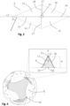
Fig. 1 is a perspective view of a thread cutting tap according to an embodiment of the invention. -
Fig. 2 is a side view of the thread cutting tap, including an enlarged view of a portion of the textured surface on the neck. -
Fig. 3 illustrates a protrusion of the textured surface as seen in a direction towards the protrusion along its protrusion extension axis. -
Fig. 4 shows a cross-section of the thread cutting tap in a section IV-IV indicated inFig. 2 , including an enlarged view of a single protrusion in such cross-section. -
Fig. 5 is a flow chart illustrating a method for manufacturing a thread cutting tap according to the invention. - All the figures are schematic, not necessarily to scale, and generally only show parts which are necessary in order to elucidate the respective embodiments, whereas other parts may be omitted or merely suggested. Unless otherwise indicated, like reference numerals refer to like parts in different figures.
- With reference to
Figs. 1-4 , athread cutting tap 1 according to an embodiment of the invention will now be described. - The
thread cutting tap 1 comprises afront end 2 and arear end 3. A longitudinal axis L extends longitudinally through the thread cutting tap from thefront end 2 to therear end 3. Athread cutting portion 4 extends rearward from thefront end 2. Thethread cutting portion 4 includes cutting lands 24 including a plurality ofthread cutting teeth 25 arranged to cut internal threads in a hole when the thread cutting tap is fed into the hole during rotational movement of the tap around the longitudinal axis L. Thethread cutting portion 4 further includesflutes 8 separating the cutting lands. Theflutes 8 extend with respect to the longitudinal axis at a helix angle λ (illustrated infig. 2 ). The thread cutting tap comprises ashank 5 extending forward from therear end 3. Theshank 5 is adapted to be arranged to a tool holder (not shown), and for example coupled to a machine tool configured to perform a thread cutting operation. - A
neck portion 6 is located between theshank 5 and thethread cutting portion 4. Theneck portion 6 has a smaller diameter than the thread cutting portion, and is not meant to engage the workpiece during a thread cutting operation. Theflutes 8 extends from thethread cutting portion 4 into theneck portion 6 in order to facilitate chip evacuation.Lands 7 are thus provided in theneck portion 6 between theflutes 8. In the illustrated embodiment, theflutes 8 do not extend over the full length of theneck portion 6, but only about 75% of the length. - The axial length LN of the
neck portion 6 is greater than the axial length LC of thethread cutting portion 4. - The
lands 7 in the neck portion has a textured surface and comprises a plurality ofprotrusions 9. In the illustrated embodiment, theprotrusions 9 completely cover all of thelands 7 in theneck portion 6, and also the part of theneck portion 6 extending rearward beyond the location where theflutes 8 end. Eachprotrusion 9 extend radially outwards from the neck portion along a protrusion extension axis A (illustrated inFig. 4 ), which in this case is perpendicular to and intersects the longitudinal axis L of the thread cutting tap. Eachprotrusion 9 extends from a neck bottom 10 to aprotrusion peak 11. - The diameter Ø of the neck portion, illustrated in
Fig. 2 , is the maximum diameter, i.e. the diameter at which the protrusion peaks 11 of theprotrusions 9 are located. - The
protrusions 9 are applied to theneck portion 6 using a knurling process, wherein a knurling tool forms right-hand trenches 20 and left-hand trenches 21 in the surface of the neck portion, schematically illustrated in dashed lines in the enlarged view infig. 2 . - Protrusions are thus formed in a pattern where the recurrence of the
protrusions 11 corresponds to a pitch P, illustrated in the enlarged view ofFig. 2 . - The resulting
protrusions 9 have the shape of truncated pyramids, as best seen inFig. 3 , showing one of the protrusions in a plan view of the neck portion from a radial direction, and inFig. 4 , showing a section perpendicular to the longitudinal axis L. In the enlarged view inFig. 4 , the section of one of the protrusions is shown in further detail. In the illustrated embodiment, the protrusion has a height H, corresponding to the shortest distance between the neck bottom and the protrusion peak, i.e. in this case the distance from the neck bottom 10 to theprotrusion peak 11 when measured along the protrusion extension axis A. - In the figures, the trenches are illustrated as having a helix angle α of about 23°, resulting in an angle 2α formed between a right-
hand trench 20 and a left-hand trench 21 of about 46°. In another exemplary embodiment corresponding to a prototype of the thread cutting tap according to the invention, a M8 thread cutting tap with a neck diameter Ø of 6 mm was provided with protrusions using a knurling process resulting in a trench helix angle α of 30°, a pitch P of 1.5 mm, and a protrusion height H of 1.2 mm. - Each pyramid shaped protrusion includes four lateral surfaces of which a
first surface 12 and asecond surface 13 face forward, whereas athird surface 15 and afourth surface 16 face rearward. In the illustrated embodiment, all fourlateral surface protrusion 9 may be slightly curved, e.g. convex. - As illustrated in
Fig. 3 , a normal N to the first surface or the second surface, when projected on a longitudinal plane perpendicular to a radial line through the protrusion (corresponding to the protrusion extension axis A in this case), forms an angle γ to the longitudinal axis L of the tap, which in the illustrated embodiment is about 67° (and would be 60° for the exemplary embodiment referred to above where the helix angle α of the trenches is 30°). At the intersection between thefirst surface 12 and thesecond surface 13, afirst edge 14 is formed. In a similar manner, asecond edge 17 is formed at the intersection between thefirst surface 12 and thethird surface 15, athird edge 18 is formed at the intersection between thesecond surface 13 and thefourth surface 16, and afourth edge 19 is formed at the intersection between thethird surface 15 and thefourth surface 16. When projected on the longitudinal plane defined above, and as seen inFig. 3 , thefirst edge 14 and thefourth edge 19 extend in parallel with the longitudinal axis L of the thread cutting tap. - As illustrated in
Fig. 4 , thesecond edge 17 forms an internal angle β to thethird edge 18, which in this case corresponds to the angle between thefirst surface 12 and thesecond surface 13, as well as the angle between thethird surface 15 and thefourth surface 16. In the illustrated embodiment, the internal angle β is about 50°. - In the following, a method for manufacturing a thread cutting tap according to an embodiment of the invention is described with reference to
Fig. 5 . - In
step 501, a blank is provided that includes a front end, a rear end and a peripheral surface, wherein the peripheral surface extends from the front end to the rear end around a central longitudinal axis. Accordingly, the blank may be a circular cylindrical body, for example made of high-speed steel. - In
step 502, a neck portion is formed in the blank, the neck portion having a smaller diameter than a portion of the blank in front thereof. This is for example achieved by turning or grinding the blank. Thereby, the portion in front of the neck portion, that will include thread cutting teeth, will be located at a greater diameter than the neck portion. - In
step 503, a knurling process is applied to the neck portion, such that at least a part of the surface of the neck portion becomes a knurled surface. Preferably, the whole neck portion is knurled. The knurling may be achieved using a knurling tool, for example arranged on a lathe. As an example, the knurling tool may include two wheels or rollers with teeth extending diagonally (left-handed for one roller and right-handed for the other roller) across the surface of the rollers. Such knurling tool is caused to engage the blank while the blank is rotated, such that one roller presses against the blank from one side and the other roller from the other side. The rollers will thereby rotate in contact with the rotating blank and form diamond shaped protrusions in the surface of the neck portion. - In
step 504, a plurality of lands are formed in the neck portion, by forming flutes separating the lands. - The flutes, for example formed by grinding, are preferably formed also in the thread cutting portion in the same operation. As a consequence of forming the flutes, some parts of the knurled surface in the neck portion are removed, but the knurled surface will remain in other regions, including the lands between the flutes.
- Although the description above contains a plurality of specificities, these should not be construed as limiting the scope of the concept described herein but as merely providing illustrations of some exemplifying embodiments of the described concept. It will be appreciated that the scope of the presently described concept fully encompasses other embodiments which may become obvious to those skilled in the art, and that the scope of the presently described concept is accordingly not to be limited.
Claims (15)
- A thread cutting tap (1), comprising- a front end (2),- a rear end (3),- a longitudinal axis (L) extending from the front end (2) to the rear end (3),- a thread cutting portion (4) extending rearward along the longitudinal axis (L) from the front end (2),- a shank (5) extending forward along the longitudinal axis (L) from the rear end (3),- a neck portion (6) located between the thread cutting portion (4) and the shank (5), wherein the neck portion (6) comprises a plurality of lands (7) separated from each other by a corresponding number of flutes (8),
characterized in that at least a part of at least one of the lands (7) in the neck portion (6) has a textured surface comprising a plurality of protrusions (9), each protrusion extending radially outwards from a neck bottom (10) to a protrusion peak (11). - A thread cutting tap according to claim 1, wherein the textured surface covers a major part of each land in the neck portion.
- A thread cutting tap according to any of the previous claims, wherein each protrusion (9) comprises a first surface (12) and a second surface (13), adjoining each other at a first edge (14) extending from the neck bottom (10) to the protrusion peak (11).
- A thread cutting tap according to claim 3, wherein the first surface and the second surface face forward, and wherein each protrusion further comprises a third surface (15) and a fourth surface (16) each facing rearward, wherein the first surface adjoins the third surface at a second edge (17) extending from the neck bottom to the protrusion peak, and the second surface adjoins the fourth surface at a third edge (18) extending from the neck bottom to the protrusion peak.
- A thread cutting tap according to any of the claims 3-4, wherein the first surface forms an internal angle (β) of 30°-90° to the second surface.
- A cutting tap according to claim 4-5, wherein each protrusion has the shape of a truncated pyramid having a square or rhombic bottom base at the neck bottom and a top base at the protrusion peak and wherein the first, second, third and fourth surfaces make up the lateral faces of the truncated pyramid, and wherein the protrusion extends along a protrusion extension axis (A) from the centroid (CB) of the bottom base to the centroid (CT) of the top base.
- A thread cutting tap according to any of the previous claims, wherein a protrusion height (H) of each protrusion, corresponding to the minimum distance between the neck bottom to the protrusion peak, is within a range of 0.05-0.35 times the diameter (Ø) of the neck portion.
- A thread cutting tap according to any of the previous claims, wherein all, or substantially all, of the protrusions have the same size and shape and are distributed over the textured surface in a pattern.
- A thread cutting tap according to claim 8, wherein the pattern is defined by a recurrence of the protrusions at a pitch (P) of 0.1-0.5 times the diameter of the neck portion.
- A thread cutting tap according to claim 9, wherein the protrusion height (H) of each protrusion is 0.5 - 0.8 times the pitch.
- A thread cutting tap according to any of the claims 8-10, wherein the pattern of the textured surface is formed by two sets of trenches (20, 21), the two sets extending along the neck portion helicoidally, but in different directions, around the longitudinal axis of the thread cutting tap, such that a trench (20) of the first set intersects a trench (21) of the second set at an angle (2α) of 30°-120°, and wherein the regions between the respective trenches form the protrusions.
- A thread cutting tap according to any of the previous claims, wherein the flutes extend with respect to the longitudinal axis at a helix angle (λ) of 30° or more.
- A thread cutting tap according to any of the previous claims, wherein the axial length (LN) of the neck portion is greater than the axial length (LC) of the thread cutting portion.
- A thread cutting tap according to any of the previous claims, wherein the textured surface is a knurled surface.
- A method for manufacturing a thread cutting tap according to claim 14, wherein the method comprises the steps of:- providing (501) a blank that includes- a front end,- a rear end, and- a peripheral surface, wherein the peripheral surface extends from the front end to the rear end around a central longitudinal axis;- forming (502) a neck portion in the peripheral surface of the blank, the neck portion having a smaller diameter than a portion of the blank in front thereof;- applying (502) a knurling process to the neck portion, such that at least a part of the neck portion becomes a knurled surface;- forming (504) a plurality of lands in the neck portion, by forming flutes separating the lands.
Priority Applications (2)
| Application Number | Priority Date | Filing Date | Title |
|---|---|---|---|
| EP23194842.3A EP4516438B1 (en) | 2023-09-01 | 2023-09-01 | Thread cutting tap with textured neck surface |
| PCT/EP2024/072430 WO2025045548A1 (en) | 2023-09-01 | 2024-08-08 | Thread cutting tap with textured neck surface |
Applications Claiming Priority (1)
| Application Number | Priority Date | Filing Date | Title |
|---|---|---|---|
| EP23194842.3A EP4516438B1 (en) | 2023-09-01 | 2023-09-01 | Thread cutting tap with textured neck surface |
Publications (3)
| Publication Number | Publication Date |
|---|---|
| EP4516438A1 true EP4516438A1 (en) | 2025-03-05 |
| EP4516438B1 EP4516438B1 (en) | 2026-04-08 |
| EP4516438C0 EP4516438C0 (en) | 2026-04-08 |
Family
ID=87929229
Family Applications (1)
| Application Number | Title | Priority Date | Filing Date |
|---|---|---|---|
| EP23194842.3A Active EP4516438B1 (en) | 2023-09-01 | 2023-09-01 | Thread cutting tap with textured neck surface |
Country Status (2)
| Country | Link |
|---|---|
| EP (1) | EP4516438B1 (en) |
| WO (1) | WO2025045548A1 (en) |
Citations (3)
| Publication number | Priority date | Publication date | Assignee | Title |
|---|---|---|---|---|
| DE202005020758U1 (en) * | 2005-07-13 | 2006-08-24 | Sagmeister, Simon | Device for removal of jammed union nut from metal tube, comprising thread cutting front area |
| CN207681660U (en) * | 2017-12-01 | 2018-08-03 | 常州蓝丁格尔工具有限公司 | A kind of one-piece hard alloy straight slot screw tap |
| EP4197692A1 (en) * | 2021-12-15 | 2023-06-21 | AB Sandvik Coromant | Thread cutting tap and method for treatment of a thread cutting tap |
-
2023
- 2023-09-01 EP EP23194842.3A patent/EP4516438B1/en active Active
-
2024
- 2024-08-08 WO PCT/EP2024/072430 patent/WO2025045548A1/en active Pending
Patent Citations (3)
| Publication number | Priority date | Publication date | Assignee | Title |
|---|---|---|---|---|
| DE202005020758U1 (en) * | 2005-07-13 | 2006-08-24 | Sagmeister, Simon | Device for removal of jammed union nut from metal tube, comprising thread cutting front area |
| CN207681660U (en) * | 2017-12-01 | 2018-08-03 | 常州蓝丁格尔工具有限公司 | A kind of one-piece hard alloy straight slot screw tap |
| EP4197692A1 (en) * | 2021-12-15 | 2023-06-21 | AB Sandvik Coromant | Thread cutting tap and method for treatment of a thread cutting tap |
Also Published As
| Publication number | Publication date |
|---|---|
| EP4516438B1 (en) | 2026-04-08 |
| EP4516438C0 (en) | 2026-04-08 |
| WO2025045548A1 (en) | 2025-03-06 |
Similar Documents
| Publication | Publication Date | Title |
|---|---|---|
| US4721421A (en) | Cutting tool with chip breakers | |
| JP5475808B2 (en) | Rotating tools and cutting inserts for cutting | |
| EP2501511B1 (en) | Cutting edge geometry in rounded nose end mills | |
| US9352400B2 (en) | Shank drill | |
| RU2370349C2 (en) | Cutting plate for face milling and milling tool | |
| JP3215429B2 (en) | Spiral cutting inserts with offset cutting edges | |
| JP3834544B2 (en) | Tap and manufacturing method thereof | |
| US20180001398A1 (en) | Cutting tool with enhanced chip evacuation capability and method of making same | |
| JP2007331097A (en) | Cutting tool | |
| JPS6328722B2 (en) | ||
| JP7006276B2 (en) | Threading cutter | |
| JP5615053B2 (en) | Manufacturing method of total cutter and grinding tool for total cutter | |
| US5213452A (en) | Router type cutter | |
| CN107107212A (en) | Formed end mill | |
| CN111230195B (en) | Ball-end milling cutter | |
| CN211360799U (en) | High-efficiency drum-shaped profiling end milling cutter | |
| EP1611983B1 (en) | High-speed processing tap | |
| US10730124B2 (en) | Taper thread-cutting spiral pipe tap | |
| US20260001149A1 (en) | Milling bit with spherical ending for cnc milling of industrial clay | |
| EP4516438B1 (en) | Thread cutting tap with textured neck surface | |
| JP2024524517A (en) | Metal cutting threading tools | |
| JP2021506599A (en) | Threading insert with variable edge roundness | |
| WO2024004890A1 (en) | Thread forming tap | |
| JP5237659B2 (en) | Cutting tap | |
| US4848976A (en) | Laminated gear shaving tools |
Legal Events
| Date | Code | Title | Description |
|---|---|---|---|
| PUAI | Public reference made under article 153(3) epc to a published international application that has entered the european phase |
Free format text: ORIGINAL CODE: 0009012 |
|
| STAA | Information on the status of an ep patent application or granted ep patent |
Free format text: STATUS: THE APPLICATION HAS BEEN PUBLISHED |
|
| AK | Designated contracting states |
Kind code of ref document: A1 Designated state(s): AL AT BE BG CH CY CZ DE DK EE ES FI FR GB GR HR HU IE IS IT LI LT LU LV MC ME MK MT NL NO PL PT RO RS SE SI SK SM TR |
|
| STAA | Information on the status of an ep patent application or granted ep patent |
Free format text: STATUS: REQUEST FOR EXAMINATION WAS MADE |
|
| 17P | Request for examination filed |
Effective date: 20250905 |
|
| GRAP | Despatch of communication of intention to grant a patent |
Free format text: ORIGINAL CODE: EPIDOSNIGR1 |
|
| STAA | Information on the status of an ep patent application or granted ep patent |
Free format text: STATUS: GRANT OF PATENT IS INTENDED |
|
| RIC1 | Information provided on ipc code assigned before grant |
Ipc: B23G 5/06 20060101AFI20251107BHEP Ipc: B23P 15/52 20060101ALI20251107BHEP |
|
| INTG | Intention to grant announced |
Effective date: 20251201 |
|
| GRAS | Grant fee paid |
Free format text: ORIGINAL CODE: EPIDOSNIGR3 |
|
| GRAA | (expected) grant |
Free format text: ORIGINAL CODE: 0009210 |
|
| STAA | Information on the status of an ep patent application or granted ep patent |
Free format text: STATUS: THE PATENT HAS BEEN GRANTED |
|
| AK | Designated contracting states |
Kind code of ref document: B1 Designated state(s): AL AT BE BG CH CY CZ DE DK EE ES FI FR GB GR HR HU IE IS IT LI LT LU LV MC ME MK MT NL NO PL PT RO RS SE SI SK SM TR |
|
| REG | Reference to a national code |
Ref country code: CH Ref legal event code: F10 Free format text: ST27 STATUS EVENT CODE: U-0-0-F10-F00 (AS PROVIDED BY THE NATIONAL OFFICE) Effective date: 20260408 Ref country code: GB Ref legal event code: FG4D |
|
| REG | Reference to a national code |
Ref country code: DE Ref legal event code: R096 Ref document number: 602023014780 Country of ref document: DE |
|
| U01 | Request for unitary effect filed |
Effective date: 20260408 |