EP4516421A1 - Method for manufacturing press-molded article - Google Patents
Method for manufacturing press-molded article Download PDFInfo
- Publication number
- EP4516421A1 EP4516421A1 EP23859738.9A EP23859738A EP4516421A1 EP 4516421 A1 EP4516421 A1 EP 4516421A1 EP 23859738 A EP23859738 A EP 23859738A EP 4516421 A1 EP4516421 A1 EP 4516421A1
- Authority
- EP
- European Patent Office
- Prior art keywords
- forming
- top plate
- outward flange
- vertical wall
- press
- Prior art date
- Legal status (The legal status is an assumption and is not a legal conclusion. Google has not performed a legal analysis and makes no representation as to the accuracy of the status listed.)
- Pending
Links
Images




Classifications
-
- B—PERFORMING OPERATIONS; TRANSPORTING
- B21—MECHANICAL METAL-WORKING WITHOUT ESSENTIALLY REMOVING MATERIAL; PUNCHING METAL
- B21D—WORKING OR PROCESSING OF SHEET METAL OR METAL TUBES, RODS OR PROFILES WITHOUT ESSENTIALLY REMOVING MATERIAL; PUNCHING METAL
- B21D53/00—Making other particular articles
- B21D53/88—Making other particular articles other parts for vehicles, e.g. cowlings, mudguards
-
- B—PERFORMING OPERATIONS; TRANSPORTING
- B21—MECHANICAL METAL-WORKING WITHOUT ESSENTIALLY REMOVING MATERIAL; PUNCHING METAL
- B21D—WORKING OR PROCESSING OF SHEET METAL OR METAL TUBES, RODS OR PROFILES WITHOUT ESSENTIALLY REMOVING MATERIAL; PUNCHING METAL
- B21D22/00—Shaping without cutting, by stamping, spinning, or deep-drawing
- B21D22/20—Deep-drawing
- B21D22/26—Deep-drawing for making peculiarly, e.g. irregularly, shaped articles
-
- B—PERFORMING OPERATIONS; TRANSPORTING
- B21—MECHANICAL METAL-WORKING WITHOUT ESSENTIALLY REMOVING MATERIAL; PUNCHING METAL
- B21D—WORKING OR PROCESSING OF SHEET METAL OR METAL TUBES, RODS OR PROFILES WITHOUT ESSENTIALLY REMOVING MATERIAL; PUNCHING METAL
- B21D19/00—Flanging or other edge treatment, e.g. of tubes
- B21D19/08—Flanging or other edge treatment, e.g. of tubes by single or successive action of pressing tools, e.g. vice jaws
-
- B—PERFORMING OPERATIONS; TRANSPORTING
- B21—MECHANICAL METAL-WORKING WITHOUT ESSENTIALLY REMOVING MATERIAL; PUNCHING METAL
- B21D—WORKING OR PROCESSING OF SHEET METAL OR METAL TUBES, RODS OR PROFILES WITHOUT ESSENTIALLY REMOVING MATERIAL; PUNCHING METAL
- B21D19/00—Flanging or other edge treatment, e.g. of tubes
-
- B—PERFORMING OPERATIONS; TRANSPORTING
- B21—MECHANICAL METAL-WORKING WITHOUT ESSENTIALLY REMOVING MATERIAL; PUNCHING METAL
- B21D—WORKING OR PROCESSING OF SHEET METAL OR METAL TUBES, RODS OR PROFILES WITHOUT ESSENTIALLY REMOVING MATERIAL; PUNCHING METAL
- B21D22/00—Shaping without cutting, by stamping, spinning, or deep-drawing
- B21D22/20—Deep-drawing
-
- B—PERFORMING OPERATIONS; TRANSPORTING
- B21—MECHANICAL METAL-WORKING WITHOUT ESSENTIALLY REMOVING MATERIAL; PUNCHING METAL
- B21D—WORKING OR PROCESSING OF SHEET METAL OR METAL TUBES, RODS OR PROFILES WITHOUT ESSENTIALLY REMOVING MATERIAL; PUNCHING METAL
- B21D24/00—Special deep-drawing arrangements in, or in connection with, presses
- B21D24/005—Multi-stage presses
Definitions
- the present invention relates to a manufacturing method of a press formed part, and more specifically relates to a manufacturing method of a press formed part having a top plate portion and vertical wall portions continuous with the top plate portion via ridge portions, and including an outward flange portion continuously formed at end portions of the top plate portion, the ridge portions, and the vertical wall portions.
- a press formed part 1 having a top plate portion 5, vertical wall portions 7, and ridge portions 9 that connect the top plate portion 5 and the vertical wall portions 7, and including an outward flange portion 3 formed continuously at end portions of the top plate portion 5, the ridge portions 9, and the vertical wall portions 7, such as a floor cross member.
- a portion of the outward flange portion 3 which portion is continuous with the ridge portion 9 (hereinafter, referred to as a "corner flange portion") becomes a stretch flange deformation, and a fracture is likely to be generated at a tip portion of the corner flange portion 3b.
- Patent Literature 1 discloses a manufacturing method of a saddle-shaped press formed part.
- a top plate forming portion of a blank is curved, first force is applied from an inner surface side to an outer surface side of the blank, and combined force of second force in a direction facing each other and third force in a direction opposite to the first force is applied to each of the outer surface side of vertical wall forming portions, and press forming is performed.
- the method disclosed in Patent Literature 1 is a method of simultaneously forming a top plate portion, vertical wall portions, and an outward flange portion.
- Patent Literature 2 discloses, as another press forming method, a press forming method of bending and raising an outward flange portion after forming a metal sheet into a U-shaped cross section.
- a press forming method of bending and raising an outward flange portion after forming a metal sheet into a U-shaped cross section.
- Patent Literature 3 discloses a press forming method of forming an outward flange by a shearing step of forming a step portion on a workpiece having a top plate, a vertical wall, and a flange, and a cutting step of cutting an unnecessary portion near the step portion.
- Patent Literature 1 a structure of a die of press forming is considerably complicated, and a manufacturing cost of a die of press forming is high.
- the combined force of the third force opposite to the first force is applied, it is difficult to perform press forming while pressing the blank sufficiently and uniformly, and it is also difficult to acquire a press formed part with high dimensional accuracy.
- Patent Literature 3 has a problem that a configuration of a die of press forming is complicated and the cutting step is essential.
- the present invention has been made in view of the above problems, and an object thereof is to provide a manufacturing method of a press formed part which method is capable of stably manufacturing a press formed part with high dimensional accuracy without causing buckling in a connection portion of a corner flange portion without using a die of press forming having a complicated structure when manufacturing a press formed part having a top plate portion and vertical wall portions continuous to the top plate portion via ridge portions, and including an outward flange portion continuously formed at end portions of the top plate portion, the ridge portions, and the vertical wall portions.
- a manufacturing method of a press formed part is the method in which the press formed part includes at least a main body portion, which has a top plate portion and vertical wall portions formed via ridge portions, and an outward flange portion formed continuously with the top plate portion, the ridge portions, and the vertical wall portions at an end portion of the main body portion.
- the method includes: an intermediate forming step of forming an intermediate formed part having the top plate portion and the vertical wall portions formed via the ridge portions, and including a step-shaped portion bulging outward at a root portion of an outward flange corresponding portion which is to be formed into the outward flange portion; and a target shape forming step of forming the outward flange portion by bending and raising the outward flange corresponding portion of the intermediate formed part outward, and acquiring a target shape.
- the top plate portion, the ridge portions, the vertical wall portions, and the step-shaped portion may be press formed in one step.
- the step-shaped portion may be press formed after the top plate portion, the ridge portions, and the vertical wall portions are press formed.
- a manufacturing method of a press formed part according to the present invention has an effect of being capable of stably manufacturing a press formed part with high dimensional accuracy without generating buckling at a connection portion of a corner flange portion without using a die of press forming having a complicated structure when manufacturing a press formed part having a top plate portion and vertical wall portions continuous to the top plate portion via ridge portions, and including an outward flange portion continuously formed at end portions of the top plate portion, the ridge portions, and the vertical wall portions.
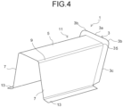
- the object of the present invention is a press formed part 1 having an outward flange portion 3, and a main body portion 11 having a top plate portion 5, vertical wall portions 7, and ridge portions 9 connecting the top plate portion 5 and the vertical wall portions 7 is included.
- the press formed part 1 has the outward flange portion 3 formed continuously with the top plate portion 5, the ridge portions 9, and the vertical wall portions 7.
- the press formed part 1 includes a horizontal flange portion 13 at a lower end of each of the vertical wall portions 7.
- portions of the outward flange portion 3 which portions are respectively continuous with the top plate portion 5, the ridge portions 9, and the vertical wall portions 7 are respectively referred to as a top plate flange portion 3a, corner flange portions 3b, and vertical wall flange portions 3c.
- FIG. 5 is a view illustrating a conventional forming method of a press formed part 1.
- an intermediate formed part 15 including a top plate portion 5, ridge portions 9, vertical wall portions 7, and a horizontal flange portion 13 at a lower end of each of the vertical wall portions 7 is first formed.
- the top plate portion 5, the ridge portions 9, and the vertical wall portions 7 are extended, and the extended portion serves as an outward flange portion 3 (top plate flange portion 3a, corner flange portions 3b, and vertical wall flange portions 3c) in a target shape.
- the extended portion is referred to as an outward flange corresponding portion 17.
- Each portion of the intermediate formed part 15 may be press formed simultaneously or may be press formed for each portion. Then, as illustrated in FIG. 5(b) , the outward flange corresponding portion 17 in the intermediate formed part 15 is bent and raised outward, whereby the outward flange portion 3 is formed and the press formed part 1 having the target shape is acquired.
- bending force is input to a top plate flange corresponding portion 17a and a vertical wall flange corresponding portion 17c. Then, in a forming method of bending and raising the outward flange corresponding portion 17 thereafter, bending force may be input to a corner flange corresponding portion 17b.
- FIG. 6 is a view illustrating a result of FEM analysis in a case where a steel sheet having a sheet thickness of 1.4 mm and tensile strength of 590 MPa-class is used, and a height of the outward flange portion 3 is 18 mm and R at a boundary portion between the top plate portion 5, the ridge portions 9, and the vertical wall portions 7 and the outward flange portion 3 is 3 mm as a target shape.
- FIG. 6 a state of the intermediate formed part 15 before forming of the outward flange portion 3 ( FIG. 6(a) ) to a state of a bottom dead center of forming after bending and raising of the outward flange portion 3 ( FIG. 6(d) ) are illustrated with intermediate stages.
- the sheet thickness increase rate is acquired by acquisition of a difference between a sheet thickness at a corresponding portion and a sheet thickness of a metal sheet as a blank and calculation of a ratio to the sheet thickness of the metal sheet as the blank.
- FIG. 7 is a view schematically illustrating a study result acquired by studying of a process in which the wrinkles and folds are generated in conventional press forming in more detail.
- states of a punch 19, a die 20, a lower pad 21, and a metal sheet 23 from a middle of forming (38 mmup) ( FIG. 7(a) ) to a vicinity of the bottom dead center of forming (4 mmup) ( FIG. 7(e) ) are illustrated with respect to a cross section cut in a direction of an arrow A along the ridge portion 9 of the press formed part 1 illustrated in FIG. 5 .
- a numerical value such as [30 mmup] is a distance in a press forming direction in which distance a sheet thickness to the bottom dead center of forming of the die 20 at the position is considered.
- the position of the die 20 at the time of "30 mmup" is +30 mm in an opposite direction of the press forming from a bottom dead center of pressing.
- the outward flange corresponding portion 17 that is an end portion of the metal sheet 23 starts coming into contact with the punch 19 at [38 mmup], and the outward flange corresponding portion 17 of the metal sheet 23 is bent and deformed in a direction of the die 20 at [30 mmup]. Then, at [24 mmup], the outward flange corresponding portion 17 is bent at a position away from the die 20 and folded in such a manner that the tip portion approaches a side of the die 20.
- a reason for such a formed shape is that the corner flange corresponding portion 17b that is an extension of the ridge portion 9 is not wound along the die 20 since the ridge portion 9 passes therethrough and rigidity against bending is high, and is folded at a position away from the die 20 (see FIG. 7(c) ).
- the vertical wall flange portion 3c (see FIG. 6 ) is not perpendicular to a surface of the top plate portion 5 of the press formed part 1 and is inclined inward. Thus, a large gap is generated between a flange forming portion of the punch 19 and a flange forming portion of the die 20 at an initial stage of the press forming.
- the present inventors have reached an idea that the above-described fold can be prevented when a portion corresponding to a root of the outward flange portion 3 of the metal sheet 23 can be wound around the die 20 in an initial stage of the press forming.
- the present invention is based on such an idea, and is specifically described below.
- a step-shaped portion 27 that is a step bulging outward is provided at a root portion of an outward flange corresponding portion 25 (top plate flange corresponding portion 25a, corner flange corresponding portion 25b, and vertical wall flange corresponding portion 25c) in an intermediate formed part 24. Then, in such an intermediate formed part 24, the outward flange corresponding portion 25 is formed into the outward flange portion 3 (top plate flange portion 3a, corner flange portion 3b, and vertical wall flange portion 3c) and a target shape is acquired. In such an intermediate formed part 24, winding around the die 20 becomes easier in the initial stage of press forming and the above-described fold can be prevented by provision of the step-shaped portion 27.
- FIG. 2(a) to FIG. 2(d) are views illustrating a result of an FEM analysis of the press forming process of the intermediate formed part 24 to the target shape.
- FIG. 2(a) the intermediate formed part 24 (before flange forming) in which the step-shaped portion 27 is formed is illustrated.
- FIG. 2(b) to FIG. 2(d) are views illustrating a forming process of the flange portion.
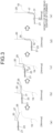
- FIG. 3 is a view schematically illustrating a forming process of forming the intermediate formed part 24 into a target shape in the press forming of the present invention.
- connection portion 31 between the ridge portion 9 and the corner flange corresponding portion 25b is wound around the die 20 from [38 mmup] to [30 mmup] since the step-shaped portion 27 is formed. Subsequently, the outward flange corresponding portion 25 starts coming into contact with the punch 19 at [30 mmup], and the tip of the metal sheet 23 is bent toward a side of the die 20 at [24 mmup]. At that time, since the step-shaped portion 27 is formed, the tip of the outward flange corresponding portion 25 does not approach the side of the die 20. Thus, the connection portion 31 between the ridge portion 9 and the corner flange corresponding portion 25b (see FIG.
- the outward flange corresponding portion 25 is formed without being folded at a gap between the die 20 and the punch 19 at [10 mmup]. Then, the forming proceeds to [4 mmup], the outward flange portion 3 is formed at the bottom dead center of forming, and the connection portion 33 between the ridge portion 9 and the corner flange portion 3b (see FIG. 1(b) ) does not become wrinkles.
- the connection portion 31 between the ridge portion 9 and the corner flange corresponding portion 25b is wound around the die 20 in the initial stage of the forming. As a result, the connection portion does not enter a gap between the lower pad 21 and the punch 19 and is not folded, and generation of the wrinkles is prevented.
- step-shaped portion 27 formed in an intermediate forming step can be press formed simultaneously with the forming of the top plate portion 5, the vertical wall portions 7, and the ridge portions 9. Since forming is performed in one step, manufacturing becomes efficient. Alternatively, the step-shaped portion 27 may be press formed after the top plate portion 5, the vertical wall portions 7, and the ridge portions 9 are formed.
- bending force is input to the top plate flange corresponding portion 25a and the vertical wall flange corresponding portion 25c. Then, the bending force is preferably input to the corner flange corresponding portion 25b. In such a manner, it is possible to prevent a fracture from being generated at the tip of the corner flange portion 3b.
- the present invention is not limited thereto. That is, the present invention may be applied to one which has no horizontal flange portion 13 and in which an orthogonal cross section of the ridge portions 9 has a U-shape, or one having a Z-shape or an L-shape acquired by half-splitting of one having a hat-shape or a U-shape in a direction of the ridge portions 9 in the top plate portion 5.
- step-shaped portion bulging outward in the present invention bending forming or drawing forming is preferable. Since the step-shaped portion is bent and the outward flange portion 3 is formed, the forming is easy even when a width of the outward flange portion 3 is wide. On the other hand, when the step-shaped portion is formed by the shear forming described in Patent literature 3, there is a not preferable case since a width of the flange portion is restricted due to a breaking limit of a material.
- a press forming analysis of the press formed part 1 that is illustrated in FIG. 4 and is the object of the present invention, and press forming of a real material were performed.
- the high tensile strength steel material a 980 MPa-class steel sheet having a sheet thickness of 1.4 mm was used.
- the press formed part 1 has a hat shape in which the top plate portion 5 has a width of 84 mm, the vertical wall portions 7 have a height of 100 mm, and the ridge portions 9 have a length of 180 mm.
- an outward flange width defined in FIG. 1(b) was set to 16 mm, and a sheet inner curvature radius R of the root portion was set to 3 mm in the cross section cut in the direction of the arrow A along the ridge portion 9.
- a press forming analysis of forming the outward flange portion 3 was performed as the conventional example and the invention example for the intermediate formed part 15 (see FIG. 5(a) ) that is press formed by utilization of a blank model of the high tensile strength steel material.
- a press forming analysis of forming the outward flange portion 3 was performed without provision of the step-shaped portion 27 at the root portion of the corner flange corresponding portion 17b.
- the invention example as illustrated in FIG.
- a press forming analysis of forming the outward flange portion 3 was performed on the intermediate formed part 24 with the step-shaped portion 27 being provided at the root portion of the corner flange corresponding portion 25b.
- a height of the step-shaped portion 27, that is, a difference in height between the step-shaped portion 27 and the top plate portion 5 was changed from 1.0 mm to 2.5 mm and the press forming analysis was performed, and an influence of the height of the step-shaped portion 27 was also compared.
- the sheet thickness increase rate of the connection portion 33 or the connection portion 35 between the ridge portion 9 and the corner flange portion 3b was acquired from the sheet thickness of the connection portion on the basis of a sheet thickness of the blank model.
- Table 1 No. Height of step-shaped portion (mm) Sheet thickness increase rate of connection portion (%) Note 1 No step 47.6 Conventional example 2 1.0 35.2 Invention example 3 1.5 28.2 Invention example 4 2.0 25.0 Invention example 5 2.5 25.9 Invention example
- the present invention can provide a manufacturing method of a press formed part which method is capable of stably producing a press formed part with high dimensional accuracy without using a die of press forming having a complicated structure and without generating buckling at a connection portion of a corner flange portion.
Landscapes
- Engineering & Computer Science (AREA)
- Mechanical Engineering (AREA)
- Shaping Metal By Deep-Drawing, Or The Like (AREA)
- Moulding By Coating Moulds (AREA)
- Casting Or Compression Moulding Of Plastics Or The Like (AREA)
- Moulds For Moulding Plastics Or The Like (AREA)
Abstract
Description
- The present invention relates to a manufacturing method of a press formed part, and more specifically relates to a manufacturing method of a press formed part having a top plate portion and vertical wall portions continuous with the top plate portion via ridge portions, and including an outward flange portion continuously formed at end portions of the top plate portion, the ridge portions, and the vertical wall portions.
- As a vehicle body collision safety is being improved due to tightening of a vehicle collision safety standard, it is also necessary to reduce weight of the vehicle body in order to improve fuel consumption and to make a shift to electric vehicles according to carbon dioxide emission control. In order to achieve both the collision safety improvement and the weight reduction of the vehicle body, application of a high strength steel sheet (also referred to as high tensile strength steel material) having a tensile strength of 590 MPa-class or more to a vehicle body structural part is in progress.
- For example, as illustrated in
FIG. 4 , as an automobile part, there is a press formedpart 1 having atop plate portion 5,vertical wall portions 7, andridge portions 9 that connect thetop plate portion 5 and thevertical wall portions 7, and including anoutward flange portion 3 formed continuously at end portions of thetop plate portion 5, theridge portions 9, and thevertical wall portions 7, such as a floor cross member. - In a case where such a press formed
part 1 is press formed, a portion of theoutward flange portion 3 which portion is continuous with the ridge portion 9 (hereinafter, referred to as a "corner flange portion") becomes a stretch flange deformation, and a fracture is likely to be generated at a tip portion of thecorner flange portion 3b. - Conventionally, with respect to a manufacturing method of a press formed part having an outward flange portion continuously formed at the end portions of the
vertical wall portions 7,Patent Literature 1 discloses a manufacturing method of a saddle-shaped press formed part. InPatent Literature 1, a top plate forming portion of a blank is curved, first force is applied from an inner surface side to an outer surface side of the blank, and combined force of second force in a direction facing each other and third force in a direction opposite to the first force is applied to each of the outer surface side of vertical wall forming portions, and press forming is performed. The method disclosed inPatent Literature 1 is a method of simultaneously forming a top plate portion, vertical wall portions, and an outward flange portion. - In addition, Patent Literature 2 discloses, as another press forming method, a press forming method of bending and raising an outward flange portion after forming a metal sheet into a U-shaped cross section. In the method disclosed in Patent Literature 2, when the outward flange portion is bent and raised, forming of the flange portion is started from a top plate portion and vertical wall portions, whereby it is assumed that a strain of the outward flange portion can be dispersed to a side of the top plate portion and sides of the vertical wall portions.
-
Patent Literature 3 discloses a press forming method of forming an outward flange by a shearing step of forming a step portion on a workpiece having a top plate, a vertical wall, and a flange, and a cutting step of cutting an unnecessary portion near the step portion. -
- Patent Literature 1:
WO 2019/216317 - Patent Literature 2:
WO 2022/049916 - Patent Literature 3:
WO 2016/194963 - In the method disclosed in
Patent Literature 1, a structure of a die of press forming is considerably complicated, and a manufacturing cost of a die of press forming is high. In addition, since the combined force of the third force opposite to the first force is applied, it is difficult to perform press forming while pressing the blank sufficiently and uniformly, and it is also difficult to acquire a press formed part with high dimensional accuracy. - In this regard, as disclosed in Patent Literature 2, in the press forming method of bending and raising the outward flange portion after forming the metal sheet into the U-shaped cross section, a die of press forming is simple and dimensional accuracy can be improved. However, in press forming of a high tensile strength steel material having further increased strength, there is a problem that buckling (wrinkles and fold) is likely to be generated at a connection portion between a ridge portion and a corner flange portion of the outward flange portion (hereinafter, simply referred to as a "connecting portion of a corner flange portion").
- In addition, the method disclosed in
Patent Literature 3 has a problem that a configuration of a die of press forming is complicated and the cutting step is essential. - The present invention has been made in view of the above problems, and an object thereof is to provide a manufacturing method of a press formed part which method is capable of stably manufacturing a press formed part with high dimensional accuracy without causing buckling in a connection portion of a corner flange portion without using a die of press forming having a complicated structure when manufacturing a press formed part having a top plate portion and vertical wall portions continuous to the top plate portion via ridge portions, and including an outward flange portion continuously formed at end portions of the top plate portion, the ridge portions, and the vertical wall portions.
- In order to solve the above-described problems and achieve the object, (1) a manufacturing method of a press formed part, according to the present invention, is the method in which the press formed part includes at least a main body portion, which has a top plate portion and vertical wall portions formed via ridge portions, and an outward flange portion formed continuously with the top plate portion, the ridge portions, and the vertical wall portions at an end portion of the main body portion. The method includes: an intermediate forming step of forming an intermediate formed part having the top plate portion and the vertical wall portions formed via the ridge portions, and including a step-shaped portion bulging outward at a root portion of an outward flange corresponding portion which is to be formed into the outward flange portion; and a target shape forming step of forming the outward flange portion by bending and raising the outward flange corresponding portion of the intermediate formed part outward, and acquiring a target shape.
- (2) Moreover, in the intermediate forming step according to above (1), the top plate portion, the ridge portions, the vertical wall portions, and the step-shaped portion may be press formed in one step.
- (3) Moreover, in the intermediate forming step according to above (1), the step-shaped portion may be press formed after the top plate portion, the ridge portions, and the vertical wall portions are press formed. Advantageous Effects of Invention
- A manufacturing method of a press formed part according to the present invention has an effect of being capable of stably manufacturing a press formed part with high dimensional accuracy without generating buckling at a connection portion of a corner flange portion without using a die of press forming having a complicated structure when manufacturing a press formed part having a top plate portion and vertical wall portions continuous to the top plate portion via ridge portions, and including an outward flange portion continuously formed at end portions of the top plate portion, the ridge portions, and the vertical wall portions.
-
-
FIG. 1 is a view for describing a manufacturing method of a press formed part according to an embodiment. -
FIG. 2 is a view illustrating an analysis result of a forming process in a target shape forming step according to the embodiment. -
FIG. 3 is a view schematically illustrating the forming process of the target shape forming step according to the embodiment. -
FIG. 4 is a view for describing an example of a press formed part to be an object of the present invention. -
FIG. 5 is a view of describing a conventional manufacturing method of a press formed part. -
FIG. 6 is a view illustrating an analysis result of a forming process of forming an outward flange portion in a conventional example. -
FIG. 7 is a view schematically illustrating the forming process of forming the outward flange portion in the conventional example. - Hereinafter, an embodiment of a manufacturing method of a press formed part according to the present invention will be described. Note that the present invention is not limited by the present embodiment.
- Before a description of the embodiment of the present invention, a shape of a press formed part to be an object of the present invention will be described with reference to
FIG. 4 illustrating an example thereof. As illustrated inFIG. 4 , the object of the present invention is a press formedpart 1 having anoutward flange portion 3, and amain body portion 11 having atop plate portion 5,vertical wall portions 7, andridge portions 9 connecting thetop plate portion 5 and thevertical wall portions 7 is included. At an end portion of themain body portion 11, the press formedpart 1 has theoutward flange portion 3 formed continuously with thetop plate portion 5, theridge portions 9, and thevertical wall portions 7. In the example illustrated inFIG. 4 , the press formedpart 1 includes ahorizontal flange portion 13 at a lower end of each of thevertical wall portions 7. Note that in the following description, portions of theoutward flange portion 3 which portions are respectively continuous with thetop plate portion 5, theridge portions 9, and thevertical wall portions 7 are respectively referred to as a topplate flange portion 3a,corner flange portions 3b, and verticalwall flange portions 3c. -
FIG. 5 is a view illustrating a conventional forming method of a press formedpart 1. Conventionally, as illustrated inFIG. 5(a) , an intermediate formedpart 15 including atop plate portion 5,ridge portions 9,vertical wall portions 7, and ahorizontal flange portion 13 at a lower end of each of thevertical wall portions 7 is first formed. At an end portion of the intermediate formedpart 15, thetop plate portion 5, theridge portions 9, and thevertical wall portions 7 are extended, and the extended portion serves as an outward flange portion 3 (topplate flange portion 3a,corner flange portions 3b, and verticalwall flange portions 3c) in a target shape. Thus, in the present embodiment, the extended portion is referred to as an outward flangecorresponding portion 17. Each portion of the intermediate formedpart 15 may be press formed simultaneously or may be press formed for each portion. Then, as illustrated inFIG. 5(b) , the outwardflange corresponding portion 17 in the intermediate formedpart 15 is bent and raised outward, whereby theoutward flange portion 3 is formed and the press formedpart 1 having the target shape is acquired. - As a forming method of bending and raising the outward flange
corresponding portion 17, for example, as disclosed in Patent Literature 2, first, bending force is input to a top plate flangecorresponding portion 17a and a vertical wall flangecorresponding portion 17c. Then, in a forming method of bending and raising the outward flangecorresponding portion 17 thereafter, bending force may be input to a corner flangecorresponding portion 17b. -
FIG. 6 is a view illustrating a result of FEM analysis in a case where a steel sheet having a sheet thickness of 1.4 mm and tensile strength of 590 MPa-class is used, and a height of theoutward flange portion 3 is 18 mm and R at a boundary portion between thetop plate portion 5, theridge portions 9, and thevertical wall portions 7 and theoutward flange portion 3 is 3 mm as a target shape. InFIG. 6 , a state of the intermediate formedpart 15 before forming of the outward flange portion 3 (FIG. 6(a) ) to a state of a bottom dead center of forming after bending and raising of the outward flange portion 3 (FIG. 6(d) ) are illustrated with intermediate stages. - Tension acts on a tip portion of the
outward flange portion 3, and a sheet thickness decreases. On the other hand, large compressive force acts on aconnection portion 35 of thecorner flange portion 3b (seeFIG. 4 ). Thus, the sheet thickness increases due to the compressive force, a maximum sheet thickness increase rate at the bottom dead center of forming becomes 47%, and wrinkles and folds are generated (seeFIG. 6(d) ). Here, the sheet thickness increase rate is acquired by acquisition of a difference between a sheet thickness at a corresponding portion and a sheet thickness of a metal sheet as a blank and calculation of a ratio to the sheet thickness of the metal sheet as the blank. -
FIG. 7 is a view schematically illustrating a study result acquired by studying of a process in which the wrinkles and folds are generated in conventional press forming in more detail. InFIG. 7 , states of apunch 19, adie 20, alower pad 21, and ametal sheet 23 from a middle of forming (38 mmup) (FIG. 7(a) ) to a vicinity of the bottom dead center of forming (4 mmup) (FIG. 7(e) ) are illustrated with respect to a cross section cut in a direction of an arrow A along theridge portion 9 of the press formedpart 1 illustrated inFIG. 5 . Note that a numerical value such as [30 mmup] is a distance in a press forming direction in which distance a sheet thickness to the bottom dead center of forming of thedie 20 at the position is considered. Thus, for example, the position of thedie 20 at the time of "30 mmup" is +30 mm in an opposite direction of the press forming from a bottom dead center of pressing. - As illustrated in
FIG. 7 , the outwardflange corresponding portion 17 that is an end portion of themetal sheet 23 starts coming into contact with thepunch 19 at [38 mmup], and the outwardflange corresponding portion 17 of themetal sheet 23 is bent and deformed in a direction of the die 20 at [30 mmup]. Then, at [24 mmup], the outwardflange corresponding portion 17 is bent at a position away from thedie 20 and folded in such a manner that the tip portion approaches a side of thedie 20. Furthermore, as the forming proceeds, a fold is generated between thelower pad 21 and a forming surface of thepunch 19 at [10 mmup], the fold remains as it is even when the forming proceeds to [4 mmup], and wrinkles are generated or the fold remains at the bottom dead center of forming. - A reason for such a formed shape is that the corner
flange corresponding portion 17b that is an extension of theridge portion 9 is not wound along the die 20 since theridge portion 9 passes therethrough and rigidity against bending is high, and is folded at a position away from the die 20 (seeFIG. 7(c) ). In addition, in the present example, the verticalwall flange portion 3c (seeFIG. 6 ) is not perpendicular to a surface of thetop plate portion 5 of the press formedpart 1 and is inclined inward. Thus, a large gap is generated between a flange forming portion of thepunch 19 and a flange forming portion of the die 20 at an initial stage of the press forming. - In considering a measure for preventing the fold of the
connection portion 35 of the cornerflange corresponding portion 17b, the present inventor has paid attention to a deformation of themetal sheet 23 in [30 mmup] to [24 mmup] ofFIG. 7 . Such a deformation is generated by a free deformation of the end portion of themetal sheet 23 and generation of the fold. In order to prevent this deformation, it is conceivable to restrain the free deformation of the end portion of themetal sheet 23. However, since it is necessary to form the cornerflange corresponding portion 17b into thecorner flange portion 3b, it is difficult to completely restrain the end portion of themetal sheet 23 with a die of press forming. Thus, the present inventors have reached an idea that the above-described fold can be prevented when a portion corresponding to a root of theoutward flange portion 3 of themetal sheet 23 can be wound around thedie 20 in an initial stage of the press forming. The present invention is based on such an idea, and is specifically described below. - As illustrated in an example in
FIG. 1(a) , a step-shapedportion 27 that is a step bulging outward is provided at a root portion of an outward flange corresponding portion 25 (top plateflange corresponding portion 25a, cornerflange corresponding portion 25b, and vertical wallflange corresponding portion 25c) in an intermediate formedpart 24. Then, in such an intermediate formedpart 24, the outwardflange corresponding portion 25 is formed into the outward flange portion 3 (topplate flange portion 3a,corner flange portion 3b, and verticalwall flange portion 3c) and a target shape is acquired. In such an intermediate formedpart 24, winding around thedie 20 becomes easier in the initial stage of press forming and the above-described fold can be prevented by provision of the step-shapedportion 27. -
FIG. 2(a) to FIG. 2(d) are views illustrating a result of an FEM analysis of the press forming process of the intermediate formedpart 24 to the target shape. InFIG. 2(a) , the intermediate formed part 24 (before flange forming) in which the step-shapedportion 27 is formed is illustrated.FIG. 2(b) to FIG. 2(d) are views illustrating a forming process of the flange portion. - Tension acts on a tip portion of the
outward flange portion 3, and a sheet thickness decreases. In addition, compressive force acts on aconnection portion 33 between theridge portion 9 and thecorner flange portion 3b (seeFIG. 1(b) ), and the sheet thickness increases. On the other hand, the maximum sheet thickness increase rate at the bottom dead center of forming is 28%, and is significantly reduced as compared with the maximum sheet thickness increase rate of 47% inFIG. 6(d) illustrating the conventional example, and it can be seen that wrinkles can be prevented. As one of the reasons why the maximum sheet thickness increase rate is reduced, in the present invention, the sheet thickness increase portion of aconnection portion 31 between theridge portion 9 and the cornerflange corresponding portion 25b (seeFIG. 1(a) ) is dispersed in [10 mmup] illustrated inFIG. 2(c) as compared with conventional [10 mmup] illustrated inFIG. 6(c) . -
FIG. 3 is a view schematically illustrating a forming process of forming the intermediate formedpart 24 into a target shape in the press forming of the present invention. InFIG. 3 , states of apunch 19, adie 20, alower pad 21, and ametal sheet 23 in a process from [38 mmup] to [4 mmup] with respect to a cross section cut in a direction of an arrow A along theridge portion 9 as illustrated inFIG. 1 . - As illustrated in
FIG. 3 , theconnection portion 31 between theridge portion 9 and the cornerflange corresponding portion 25b is wound around the die 20 from [38 mmup] to [30 mmup] since the step-shapedportion 27 is formed. Subsequently, the outwardflange corresponding portion 25 starts coming into contact with thepunch 19 at [30 mmup], and the tip of themetal sheet 23 is bent toward a side of the die 20 at [24 mmup]. At that time, since the step-shapedportion 27 is formed, the tip of the outwardflange corresponding portion 25 does not approach the side of thedie 20. Thus, theconnection portion 31 between theridge portion 9 and the cornerflange corresponding portion 25b (seeFIG. 1(a) ) is not bent at an acute angle. In this regard, at [24 mmup] ofFIG. 7 illustrating the conventional example, the tip of the outwardflange corresponding portion 25 approaches the side of the die 20, and theconnection portion 35 between theridge portion 9 and thecorner flange portion 3b (seeFIG. 4 ) is bent at an acute angle. - Furthermore, as the press forming proceeds, the outward
flange corresponding portion 25 is formed without being folded at a gap between the die 20 and thepunch 19 at [10 mmup]. Then, the forming proceeds to [4 mmup], theoutward flange portion 3 is formed at the bottom dead center of forming, and theconnection portion 33 between theridge portion 9 and thecorner flange portion 3b (seeFIG. 1(b) ) does not become wrinkles. As described above, in the present embodiment, since the step-shapedportion 27 is provided, theconnection portion 31 between theridge portion 9 and the cornerflange corresponding portion 25b is wound around thedie 20 in the initial stage of the forming. As a result, the connection portion does not enter a gap between thelower pad 21 and thepunch 19 and is not folded, and generation of the wrinkles is prevented. - Note that the step-shaped
portion 27 formed in an intermediate forming step can be press formed simultaneously with the forming of thetop plate portion 5, thevertical wall portions 7, and theridge portions 9. Since forming is performed in one step, manufacturing becomes efficient. Alternatively, the step-shapedportion 27 may be press formed after thetop plate portion 5, thevertical wall portions 7, and theridge portions 9 are formed. - In addition, in a target shape forming step of forming the
outward flange portion 3, as disclosed in Patent Literature 2, first, bending force is input to the top plateflange corresponding portion 25a and the vertical wallflange corresponding portion 25c. Then, the bending force is preferably input to the cornerflange corresponding portion 25b. In such a manner, it is possible to prevent a fracture from being generated at the tip of thecorner flange portion 3b. - Note that in the above description, although the
vertical wall portions 7 are provided on both sides of thetop plate portion 5, thehorizontal flange portions 13 are included at the lower ends of thevertical wall portions 7, and an orthogonal cross section of theridge portions 9 has a hat shape, the present invention is not limited thereto. That is, the present invention may be applied to one which has nohorizontal flange portion 13 and in which an orthogonal cross section of theridge portions 9 has a U-shape, or one having a Z-shape or an L-shape acquired by half-splitting of one having a hat-shape or a U-shape in a direction of theridge portions 9 in thetop plate portion 5. In addition, in order to form the step-shaped portion bulging outward in the present invention, bending forming or drawing forming is preferable. Since the step-shaped portion is bent and theoutward flange portion 3 is formed, the forming is easy even when a width of theoutward flange portion 3 is wide. On the other hand, when the step-shaped portion is formed by the shear forming described inPatent literature 3, there is a not preferable case since a width of the flange portion is restricted due to a breaking limit of a material. - In the present example, in order to confirm an effect of the present invention, a press forming analysis of the press formed
part 1 that is illustrated inFIG. 4 and is the object of the present invention, and press forming of a real material were performed. As the high tensile strength steel material, a 980 MPa-class steel sheet having a sheet thickness of 1.4 mm was used. The press formedpart 1 has a hat shape in which thetop plate portion 5 has a width of 84 mm, thevertical wall portions 7 have a height of 100 mm, and theridge portions 9 have a length of 180 mm. For theoutward flange portion 3, an outward flange width defined inFIG. 1(b) was set to 16 mm, and a sheet inner curvature radius R of the root portion was set to 3 mm in the cross section cut in the direction of the arrow A along theridge portion 9. - In addition, in the present example, a press forming analysis of forming the
outward flange portion 3 was performed as the conventional example and the invention example for the intermediate formed part 15 (seeFIG. 5(a) ) that is press formed by utilization of a blank model of the high tensile strength steel material. As the conventional example, as illustrated inFIG. 5 andFIG. 6 , a press forming analysis of forming theoutward flange portion 3 was performed without provision of the step-shapedportion 27 at the root portion of the cornerflange corresponding portion 17b. In addition, as the invention example, as illustrated inFIG. 1(a) , a press forming analysis of forming theoutward flange portion 3 was performed on the intermediate formedpart 24 with the step-shapedportion 27 being provided at the root portion of the cornerflange corresponding portion 25b. In addition, in the invention example, a height of the step-shapedportion 27, that is, a difference in height between the step-shapedportion 27 and thetop plate portion 5 was changed from 1.0 mm to 2.5 mm and the press forming analysis was performed, and an influence of the height of the step-shapedportion 27 was also compared. Note that the sheet thickness increase rate of theconnection portion 33 or theconnection portion 35 between theridge portion 9 and thecorner flange portion 3b was acquired from the sheet thickness of the connection portion on the basis of a sheet thickness of the blank model. Results of the analysis are illustrated in Table 1.Table 1 No. Height of step-shaped portion (mm) Sheet thickness increase rate of connection portion (%) Note 1 No step 47.6 Conventional example 2 1.0 35.2 Invention example 3 1.5 28.2 Invention example 4 2.0 25.0 Invention example 5 2.5 25.9 Invention example - In a case of No. 1 that is the conventional example in which the step-shaped
portion 27 is not provided, the maximum sheet thickness increase rate was as large as 47.6%. In the actual press material, buckling (wrinkles and fold) was generated at theconnection portion 35 between theridge portion 9 and thecorner flange portion 3b. On the other hand, in each of invention examples No. 2 to No. 5 in which the step-shapedportion 27 was provided, the maximum sheet thickness increase rate was greatly decreased as the analysis result. In addition, buckling was not generated in actual press materials of these. Note that in a case of No. 4 in which the height of the step-shapedportion 27 was 2.0 mm, the maximum sheet thickness increase rate was 25%, was decreased the most, and was almost halved compared to 47.6% of the conventional example. As described above, it has been demonstrated that buckling of theconnection portion 33 between theridge portion 9 and thecorner flange portion 3b can be prevented by provision of the step-shapedportion 27 in the intermediate formedpart 24 of the present invention. - The present invention can provide a manufacturing method of a press formed part which method is capable of stably producing a press formed part with high dimensional accuracy without using a die of press forming having a complicated structure and without generating buckling at a connection portion of a corner flange portion.
-
- 1 PRESS FORMED PART
- 3 OUTWARD FLANGE PORTION
- 3a TOP PLATE FLANGE PORTION
- 3b CORNER FLANGE PORTION
- 3c VERTICAL WALL FLANGE PORTION
- 5 TOP PLATE PORTION
- 7 VERTICAL WALL PORTION
- 9 RIDGE PORTION
- 11 MAIN BODY PORTION
- 13 HORIZONTAL FLANGE PORTION
- 15 INTERMEDIATE FORMED PART (CONVENTIONAL EXAMPLE)
- 17 OUTWARD FLANGE CORRESPONDING PORTION (CONVENTIONAL EXAMPLE)
- 17a TOP PLATE FLANGE CORRESPONDING PORTION (CONVENTIONAL EXAMPLE)
- 17b CORNER FLANGE CORRESPONDING PORTION (CONVENTIONAL EXAMPLE)
- 17c VERTICAL WALL FLANGE CORRESPONDING PORTION (CONVENTIONAL EXAMPLE)
- 19 PUNCH
- 20 DIE
- 21 LOWER PAD
- 23 METAL SHEET
- 24 INTERMEDIATE FORMED PART (INVENTION EXAMPLE)
- 25 OUTWARD FLANGE CORRESPONDING PORTION (INVENTION EXAMPLE)
- 25a TOP PLATE FLANGE CORRESPONDING PORTION (INVENTION EXAMPLE)
- 25b CORNER FLANGE CORRESPONDING PORTION (INVENTION EXAMPLE)
- 25c VERTICAL WALL FLANGE CORRESPONDING PORTION (INVENTION EXAMPLE)
- 27 STEP-SHAPED PORTION
- 31 CONNECTION PORTION BETWEEN RIDGE PORTION AND CORNER FLANGE PORTION OF INTERMEDIATE FORMED PART (INVENTION EXAMPLE)
- 33 CONNECTION PORTION BETWEEN RIDGE PORTION AND CORNER FLANGE PORTION OF PRESS FORMED PART (INVENTION EXAMPLE)
- 35 CONNECTION PORTION BETWEEN RIDGE PORTION AND CORNER FLANGE PORTION (CONVENTIONAL EXAMPLE)
Claims (3)
- A manufacturing method of a press formed part, the press formed part including at leasta main body portion, which has a top plate portion and vertical wall portions formed via ridge portions, andan outward flange portion formed continuously with the top plate portion, the ridge portions, and the vertical wall portions at an end portion of the main body portion, the method comprising:an intermediate forming step of forming an intermediate formed part having the top plate portion and the vertical wall portions formed via the ridge portions, and including a step-shaped portion bulging outward at a root portion of an outward flange corresponding portion which is to be formed into the outward flange portion; anda target shape forming step of forming the outward flange portion by bending and raising the outward flange corresponding portion of the intermediate formed part outward, and acquiring a target shape.
- The manufacturing method of a press formed part according to claim 1, wherein in the intermediate forming step, the top plate portion, the ridge portions, the vertical wall portions, and the step-shaped portion are press formed in one step.
- The manufacturing method of a press formed part according to claim 1, wherein in the intermediate forming step, the step-shaped portion is press formed after the top plate portion, the ridge portions, and the vertical wall portions are press formed.
Applications Claiming Priority (2)
| Application Number | Priority Date | Filing Date | Title |
|---|---|---|---|
| JP2022135517 | 2022-08-29 | ||
| PCT/JP2023/019071 WO2024047968A1 (en) | 2022-08-29 | 2023-05-23 | Method for manufacturing press-molded article |
Publications (2)
| Publication Number | Publication Date |
|---|---|
| EP4516421A1 true EP4516421A1 (en) | 2025-03-05 |
| EP4516421A4 EP4516421A4 (en) | 2025-06-18 |
Family
ID=90099324
Family Applications (1)
| Application Number | Title | Priority Date | Filing Date |
|---|---|---|---|
| EP23859738.9A Pending EP4516421A4 (en) | 2022-08-29 | 2023-05-23 | METHOD OF MANUFACTURING A PRESS-MOLDED ARTICLE |
Country Status (7)
| Country | Link |
|---|---|
| US (1) | US20250339887A1 (en) |
| EP (1) | EP4516421A4 (en) |
| JP (1) | JP7586339B2 (en) |
| KR (1) | KR20250040052A (en) |
| CN (1) | CN119677600A (en) |
| MX (1) | MX2025002348A (en) |
| WO (1) | WO2024047968A1 (en) |
Family Cites Families (5)
| Publication number | Priority date | Publication date | Assignee | Title |
|---|---|---|---|---|
| TWI574755B (en) * | 2013-03-21 | 2017-03-21 | Nippon Steel & Sumitomo Metal Corp | A method of manufacturing a press-formed member, and a press-forming device |
| CA2986084C (en) * | 2015-06-01 | 2020-04-14 | Nippon Steel Corporation | Press-formed article, press-forming method, and press-forming apparatus |
| WO2019216317A1 (en) | 2018-05-11 | 2019-11-14 | 日本製鉄株式会社 | Manufacturing method for saddle-shaped press-molded article, press-molding device, and manufacturing method for manufacturing saddle-shaped press-molded article |
| EP4209286A4 (en) | 2020-09-03 | 2024-06-12 | JFE Steel Corporation | METHOD FOR MANUFACTURING A PRESS-FORMED ARTICLE AND PRESSING DEVICE |
| JP7539307B2 (en) * | 2020-12-09 | 2024-08-23 | 東プレ株式会社 | Manufacturing method for pressed parts |
-
2023
- 2023-05-23 WO PCT/JP2023/019071 patent/WO2024047968A1/en not_active Ceased
- 2023-05-23 CN CN202380059093.2A patent/CN119677600A/en active Pending
- 2023-05-23 US US18/870,934 patent/US20250339887A1/en active Pending
- 2023-05-23 KR KR1020257005534A patent/KR20250040052A/en active Pending
- 2023-05-23 JP JP2023551205A patent/JP7586339B2/en active Active
- 2023-05-23 EP EP23859738.9A patent/EP4516421A4/en active Pending
-
2025
- 2025-02-26 MX MX2025002348A patent/MX2025002348A/en unknown
Also Published As
| Publication number | Publication date |
|---|---|
| JP7586339B2 (en) | 2024-11-19 |
| CN119677600A (en) | 2025-03-21 |
| US20250339887A1 (en) | 2025-11-06 |
| KR20250040052A (en) | 2025-03-21 |
| EP4516421A4 (en) | 2025-06-18 |
| MX2025002348A (en) | 2025-04-02 |
| JPWO2024047968A1 (en) | 2024-03-07 |
| WO2024047968A1 (en) | 2024-03-07 |
Similar Documents
| Publication | Publication Date | Title |
|---|---|---|
| JP6281670B1 (en) | Press part manufacturing method and manufacturing apparatus | |
| US9839954B2 (en) | Method for producing center pillar reinforcement | |
| JP5836972B2 (en) | Manufacturing method of L-shaped products | |
| EP3272438B1 (en) | Method for producing press-molded product, press-molded product, and pressing device | |
| CN105188980B (en) | The manufacture method of press-formed part and press molding equipment | |
| CN109952165B (en) | Method and apparatus for manufacturing press-formed article | |
| EP3320996B1 (en) | Method and apparatus for manufacturing press component | |
| CN111727089B (en) | Method for manufacturing press-molded member, press-molding device, and metal plate for press-molding | |
| CN107107968B (en) | structural member | |
| KR20150038417A (en) | Method for producing curved article and skeleton structure member for automobile body shell | |
| JP6330930B1 (en) | Press forming method | |
| US11951526B2 (en) | Press-formed product manufacturing method and forming die | |
| CN107148320A (en) | The manufacture method and manufacture device of compressing product | |
| KR102001328B1 (en) | Press forming method and tool of press forming | |
| EP3970873A1 (en) | Press-forming method | |
| EP4144455B1 (en) | Press-molding die and press-molding method | |
| CN119816386A (en) | Manufacturing method of stamped product | |
| US20250339887A1 (en) | Manufacturing method of press formed part | |
| EP4321269A1 (en) | Press forming method | |
| JP7448464B2 (en) | Manufacturing method of steel parts | |
| JP7604321B2 (en) | Manufacturing method for pressed parts for vehicles | |
| EP4454777A1 (en) | Press-molding method and press-molded article manufacturing method | |
| JP2023117363A (en) | Press molding method and method for manufacturing press molded product | |
| EP4610147A1 (en) | Structural component for automobile, and method for manufacturing pressed component |
Legal Events
| Date | Code | Title | Description |
|---|---|---|---|
| STAA | Information on the status of an ep patent application or granted ep patent |
Free format text: STATUS: THE INTERNATIONAL PUBLICATION HAS BEEN MADE |
|
| PUAI | Public reference made under article 153(3) epc to a published international application that has entered the european phase |
Free format text: ORIGINAL CODE: 0009012 |
|
| STAA | Information on the status of an ep patent application or granted ep patent |
Free format text: STATUS: REQUEST FOR EXAMINATION WAS MADE |
|
| 17P | Request for examination filed |
Effective date: 20241128 |
|
| AK | Designated contracting states |
Kind code of ref document: A1 Designated state(s): AL AT BE BG CH CY CZ DE DK EE ES FI FR GB GR HR HU IE IS IT LI LT LU LV MC ME MK MT NL NO PL PT RO RS SE SI SK SM TR |
|
| REG | Reference to a national code |
Ref country code: DE Ref legal event code: R079 Free format text: PREVIOUS MAIN CLASS: B21D0022260000 Ipc: B21D0019080000 |
|
| A4 | Supplementary search report drawn up and despatched |
Effective date: 20250521 |
|
| RIC1 | Information provided on ipc code assigned before grant |
Ipc: B21D 53/88 20060101ALI20250515BHEP Ipc: B21D 22/20 20060101ALI20250515BHEP Ipc: B21D 19/08 20060101AFI20250515BHEP |
|
| DAV | Request for validation of the european patent (deleted) | ||
| DAX | Request for extension of the european patent (deleted) |