EP4516411A1 - Motor operated dispensing device with cutting blade - Google Patents
Motor operated dispensing device with cutting blade Download PDFInfo
- Publication number
- EP4516411A1 EP4516411A1 EP24194354.7A EP24194354A EP4516411A1 EP 4516411 A1 EP4516411 A1 EP 4516411A1 EP 24194354 A EP24194354 A EP 24194354A EP 4516411 A1 EP4516411 A1 EP 4516411A1
- Authority
- EP
- European Patent Office
- Prior art keywords
- dispensing device
- elongate member
- motor
- assembly
- front support
- Prior art date
- Legal status (The legal status is an assumption and is not a legal conclusion. Google has not performed a legal analysis and makes no representation as to the accuracy of the status listed.)
- Pending
Links
Images










Classifications
-
- B—PERFORMING OPERATIONS; TRANSPORTING
- B05—SPRAYING OR ATOMISING IN GENERAL; APPLYING FLUENT MATERIALS TO SURFACES, IN GENERAL
- B05C—APPARATUS FOR APPLYING FLUENT MATERIALS TO SURFACES, IN GENERAL
- B05C17/00—Hand tools or apparatus using hand held tools, for applying liquids or other fluent materials to, for spreading applied liquids or other fluent materials on, or for partially removing applied liquids or other fluent materials from, surfaces
- B05C17/005—Hand tools or apparatus using hand held tools, for applying liquids or other fluent materials to, for spreading applied liquids or other fluent materials on, or for partially removing applied liquids or other fluent materials from, surfaces for discharging material from a reservoir or container located in or on the hand tool through an outlet orifice by pressure without using surface contacting members like pads or brushes
- B05C17/01—Hand tools or apparatus using hand held tools, for applying liquids or other fluent materials to, for spreading applied liquids or other fluent materials on, or for partially removing applied liquids or other fluent materials from, surfaces for discharging material from a reservoir or container located in or on the hand tool through an outlet orifice by pressure without using surface contacting members like pads or brushes with manually mechanically or electrically actuated piston or the like
- B05C17/0103—Hand tools or apparatus using hand held tools, for applying liquids or other fluent materials to, for spreading applied liquids or other fluent materials on, or for partially removing applied liquids or other fluent materials from, surfaces for discharging material from a reservoir or container located in or on the hand tool through an outlet orifice by pressure without using surface contacting members like pads or brushes with manually mechanically or electrically actuated piston or the like with electrically actuated piston or the like
-
- B—PERFORMING OPERATIONS; TRANSPORTING
- B05—SPRAYING OR ATOMISING IN GENERAL; APPLYING FLUENT MATERIALS TO SURFACES, IN GENERAL
- B05C—APPARATUS FOR APPLYING FLUENT MATERIALS TO SURFACES, IN GENERAL
- B05C17/00—Hand tools or apparatus using hand held tools, for applying liquids or other fluent materials to, for spreading applied liquids or other fluent materials on, or for partially removing applied liquids or other fluent materials from, surfaces
- B05C17/005—Hand tools or apparatus using hand held tools, for applying liquids or other fluent materials to, for spreading applied liquids or other fluent materials on, or for partially removing applied liquids or other fluent materials from, surfaces for discharging material from a reservoir or container located in or on the hand tool through an outlet orifice by pressure without using surface contacting members like pads or brushes
- B05C17/0052—Accessories therefor
-
- B—PERFORMING OPERATIONS; TRANSPORTING
- B05—SPRAYING OR ATOMISING IN GENERAL; APPLYING FLUENT MATERIALS TO SURFACES, IN GENERAL
- B05C—APPARATUS FOR APPLYING FLUENT MATERIALS TO SURFACES, IN GENERAL
- B05C17/00—Hand tools or apparatus using hand held tools, for applying liquids or other fluent materials to, for spreading applied liquids or other fluent materials on, or for partially removing applied liquids or other fluent materials from, surfaces
- B05C17/005—Hand tools or apparatus using hand held tools, for applying liquids or other fluent materials to, for spreading applied liquids or other fluent materials on, or for partially removing applied liquids or other fluent materials from, surfaces for discharging material from a reservoir or container located in or on the hand tool through an outlet orifice by pressure without using surface contacting members like pads or brushes
- B05C17/01—Hand tools or apparatus using hand held tools, for applying liquids or other fluent materials to, for spreading applied liquids or other fluent materials on, or for partially removing applied liquids or other fluent materials from, surfaces for discharging material from a reservoir or container located in or on the hand tool through an outlet orifice by pressure without using surface contacting members like pads or brushes with manually mechanically or electrically actuated piston or the like
- B05C17/0106—Hand tools or apparatus using hand held tools, for applying liquids or other fluent materials to, for spreading applied liquids or other fluent materials on, or for partially removing applied liquids or other fluent materials from, surfaces for discharging material from a reservoir or container located in or on the hand tool through an outlet orifice by pressure without using surface contacting members like pads or brushes with manually mechanically or electrically actuated piston or the like with means for longitudinally cutting container walls during relative displacement of the piston and its cooperating container
-
- B—PERFORMING OPERATIONS; TRANSPORTING
- B05—SPRAYING OR ATOMISING IN GENERAL; APPLYING FLUENT MATERIALS TO SURFACES, IN GENERAL
- B05C—APPARATUS FOR APPLYING FLUENT MATERIALS TO SURFACES, IN GENERAL
- B05C17/00—Hand tools or apparatus using hand held tools, for applying liquids or other fluent materials to, for spreading applied liquids or other fluent materials on, or for partially removing applied liquids or other fluent materials from, surfaces
- B05C17/005—Hand tools or apparatus using hand held tools, for applying liquids or other fluent materials to, for spreading applied liquids or other fluent materials on, or for partially removing applied liquids or other fluent materials from, surfaces for discharging material from a reservoir or container located in or on the hand tool through an outlet orifice by pressure without using surface contacting members like pads or brushes
- B05C17/01—Hand tools or apparatus using hand held tools, for applying liquids or other fluent materials to, for spreading applied liquids or other fluent materials on, or for partially removing applied liquids or other fluent materials from, surfaces for discharging material from a reservoir or container located in or on the hand tool through an outlet orifice by pressure without using surface contacting members like pads or brushes with manually mechanically or electrically actuated piston or the like
- B05C17/0116—Hand tools or apparatus using hand held tools, for applying liquids or other fluent materials to, for spreading applied liquids or other fluent materials on, or for partially removing applied liquids or other fluent materials from, surfaces for discharging material from a reservoir or container located in or on the hand tool through an outlet orifice by pressure without using surface contacting members like pads or brushes with manually mechanically or electrically actuated piston or the like characterised by the piston driving means
-
- B—PERFORMING OPERATIONS; TRANSPORTING
- B05—SPRAYING OR ATOMISING IN GENERAL; APPLYING FLUENT MATERIALS TO SURFACES, IN GENERAL
- B05C—APPARATUS FOR APPLYING FLUENT MATERIALS TO SURFACES, IN GENERAL
- B05C17/00—Hand tools or apparatus using hand held tools, for applying liquids or other fluent materials to, for spreading applied liquids or other fluent materials on, or for partially removing applied liquids or other fluent materials from, surfaces
- B05C17/005—Hand tools or apparatus using hand held tools, for applying liquids or other fluent materials to, for spreading applied liquids or other fluent materials on, or for partially removing applied liquids or other fluent materials from, surfaces for discharging material from a reservoir or container located in or on the hand tool through an outlet orifice by pressure without using surface contacting members like pads or brushes
- B05C17/01—Hand tools or apparatus using hand held tools, for applying liquids or other fluent materials to, for spreading applied liquids or other fluent materials on, or for partially removing applied liquids or other fluent materials from, surfaces for discharging material from a reservoir or container located in or on the hand tool through an outlet orifice by pressure without using surface contacting members like pads or brushes with manually mechanically or electrically actuated piston or the like
- B05C17/0116—Hand tools or apparatus using hand held tools, for applying liquids or other fluent materials to, for spreading applied liquids or other fluent materials on, or for partially removing applied liquids or other fluent materials from, surfaces for discharging material from a reservoir or container located in or on the hand tool through an outlet orifice by pressure without using surface contacting members like pads or brushes with manually mechanically or electrically actuated piston or the like characterised by the piston driving means
- B05C17/0133—Nut and bolt advancing mechanism, e.g. threaded piston rods
-
- B—PERFORMING OPERATIONS; TRANSPORTING
- B05—SPRAYING OR ATOMISING IN GENERAL; APPLYING FLUENT MATERIALS TO SURFACES, IN GENERAL
- B05C—APPARATUS FOR APPLYING FLUENT MATERIALS TO SURFACES, IN GENERAL
- B05C17/00—Hand tools or apparatus using hand held tools, for applying liquids or other fluent materials to, for spreading applied liquids or other fluent materials on, or for partially removing applied liquids or other fluent materials from, surfaces
- B05C17/005—Hand tools or apparatus using hand held tools, for applying liquids or other fluent materials to, for spreading applied liquids or other fluent materials on, or for partially removing applied liquids or other fluent materials from, surfaces for discharging material from a reservoir or container located in or on the hand tool through an outlet orifice by pressure without using surface contacting members like pads or brushes
- B05C17/00596—The liquid or other fluent material being supplied from a rigid removable cartridge having no active dispensing means, i.e. the cartridge requiring cooperation with means of the handtool to expel the material
Definitions
- the present disclosure relates to a hand held viscous material dispensing device.
- Cartridges or containers of viscous material such as gels, glues, caulk, silicone or sealants or pastes provide a convenient selection of materials used for filling gaps or sealing cracks in construction or maintenance projects on building sites all around the world. Application of these materials waterproof or seal around window frames, reduce the flow of heat into/out of the home, fill cracks or seal surfaces and are vital in finishing a variety of construction projects.
- material in these cartridges or containers are applied using a manually actuated or motor driven caulking gun or silicone gun.
- Such applicator devices expel viscous material from the cartridge through a nozzle of the cartridge into the crack or onto the work surface.
- caulking guns One common arrangement of manual cartridge application tools, typically known as caulking guns, is a lever which is grasped by a user. Typically, the grasping by the user urges a plunger against one end of the cartridge which is retained in the barrel of the caulking gun, shortening the effective length of the cartridge and expelling the viscous material from the tip through a nozzle.
- Other arrangements may be configured so that grasping of a lever by the user drive the cartridge back against a fixed base, thereby urging viscous material from the nozzle.
- a dispensing device for dispensing viscous material from a container received therein, said device comprising:
- the motor and gear assembly may be configured to drive the elongate member such that the front support is retracted towards the rear plunger assembly upon actuation of said motor.
- the rear plunger assembly is preferably disposed under the rear plunger assembly in the main housing.
- the motor and gear assembly are disposed substantially within a handle shaped portion defined by the main housing.
- the rear plunger assembly housing is generally circular in cross section and is rotatably received in a corresponding circular aperture having a relatively larger diameter defined in the main housing.
- the device has a length from the front support to the end of the main housing in an extended state of between approximately 310 mm and 370 mm, and optionally between approximately 320mm and 340mm.
- the device has a length from the front support to the end of the main housing of approximately 280 mm and 340 mm, and optionally between approximately 310mm and 320mm.
- the elongate member and front support are detachable from the main housing.
- the elongate member is a toothed rack which is driven by a pinion gear of the gear assembly upon actuation of the motor.
- the motor and gear assembly may be configured to drive the elongate member such that the rear plunger assembly is driven towards front assembly upon actuation of the motor.
- the elongate member may be an externally threaded rod coupled via the gear assembly to the motor via a lead screw nut movable thereon such that rotation of said motor drives the rear plunger assembly towards and away from the front support.
- the device has a length from front of the main housing to the end of the at least one elongate member of approximately 250mm and 300mm and optionally between 260 and 280mm.
- the device has a length from the front support to the end of the main housing of between 250 and 300 mm which does not change as the plunger moves from a retracted to extended state.
- the lead screw nut comprises a pair of split nuts which are engageable and disengageable from the externally threaded rod via a user actuable lever.
- the disclosed technology addresses the need in the art for an improved dispensing device which is reduced in size and which provides an easy to use and control alternative to other dispensing devices.
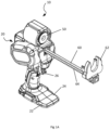
- FIGs 1A - 1D there are depicted various views of the dispensing device according to a first embodiment of the present disclosure, without the cartridge or container (used interchangeably) of viscous material, for clarity purposes.
- the device 10 includes a main housing 20 comprising right housing 22 and left housing 24.
- a trigger switch 26 is received between these housings, and this switch is arranged to be actuated by the users finger to provide power from the battery or power cell (not shown ) to drive the motor 30 and gear assembly 40.
- the plunger assembly 50 is received in the top of the main housing 20 above the motor 30 and gear assembly 40 as described herein.
- An elongate member 60 is received in the main housing at one end.
- a front support 62 is attached to the other end of the elongate member 60.
- the elongate member 60 is a toothed rack which is driven by a pinion gear 49 of the gear assembly 40 upon actuation of the motor 30.
- the front support 62 is spaced far enough apart from the rear plunger assembly 50 to receive full standard sized containers of viscous material and retain these containers with the neck of the container and base of the nozzle resting in the front support 62, whilst the base of the container contacts the plunger assembly 50.
- the rear plunger is disposed in the main housing.
- the motor 30 and gear assembly 40 are disposed substantially within the handle shaped portion of the main housing.
- the gear assembly 40 comprises a four layers of planetary gears, a first layer of planetary gears 42a, a second layer of planetary gears 44b, a third layer of planetary gears 42c and a fourth layer of planetary gears 42d.
- the plunger assembly 50 comprises a plunger plate 52 supported by a cutting edge 54 in a housing 56.
- the actuation of the motor 30 by the user activating the trigger 26 retracts the front support 62 of the elongate member 60 towards the rear plunger assembly 50. Teeth of spur gear 49 mesh with corresponding teeth 64 of the elongate member 60, changing the rotational motion of the gear assembly 40 into linear motion of the elongate member 60. As is known to persons skilled in the art, changing the direction of rotation of the motor will change the direction of travel of the elongate member 60 relative to the housing.
- the rear plunger assembly 50 is thus urged against an end or base of the container, which drives the plunger plate 52 inside the container toward the nozzle and thereby extrudes the viscous material in the container onto the work surface.
- the rear plunger assembly is arranged to cut into the side of the container.
- the cutting of the container by the rear plunger assembly enables the front support to be retracted towards the rear plunger assembly as the elongate member is driven via the gear assembly by the motor.
- the rear plunger assembly is driven via the gear assembly by the motor toward the front support.
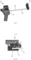
- the device 10 may be configured such that the elongate member 60 may be disengaged from the housing 20. This further assists in reducing the size taken up the dispensing device when stored. As depicted, the user actuates a disengagement button 25 and then pulls the elongate member 60 to release it.
- the elongate member 60 cannot be pulled out from the main housing as the pin 48 is engaged with the end of the elongate member 60.
- this button pivots within the housing and lifts the pin 48 out from engagement with the end of the elongate member 60 as shown in Fig 2C(ii) .
- This means that the elongate member 60 can then be removed from the housing as depicted in Fig 2B .
- a rubber rod 27 may further be disposed in the housing and arranged to bear against the elongate member 60.
- This rod is depicted in storage configuration in the figure, but it would be appreciated that this rod is configured to provide frictional engagement of the elongate member and prevent it moving backwards and forwards during normal operation too easily relative to the main housing.
- the length of the device can be configured so that the length from the front support to the end of the main housing in an extended state of between 330mm -350mm.
- An exemplary full container of viscous material 80 is shown for reference, received between the rear plunger assembly 50 and the front support member with the nozzle 82 protruding forwards.
- length of the elongate member and/or the physical size parameters of the housing may be selected so as to provide these dimensions.
- the length is 338mm, but it would be appreciated that other sizes in the range of 280mm - 370mm could also be selected, and more preferably 300-350mm.
- the length from front of the main housing to the end of the at least one elongate member is approximately 240mm - 300mm, and preferably 260 mm-280mm. More particularly, in the embodiment depicted the length is 270mm.
- Fig 4A - Fig 4C a smaller version of the first embodiment of the device 110 described herein in which the front support 162 is also moveable towards and away from the rear plunger assembly 150.
- the front support 162 is spaced apart from the main housing 120 by elongate member 160.
- the elongate member 160 is a toothed rack which is driven by spur gear 149 of the gear assembly 140 upon actuation of the motor 130.
- a rear plunger assembly 150 is disposed in the main housing 120, above the motor 130 and gear assembly 140 which in this embodiment is small enough such that it is substantially disposed in the handle under the rear plunger assembly 150. It would be appreciated that a user can grip the housing with their fingers. Layers of planetary gears 142a, 142b, 142c are arranged above the motor 130. These mesh with further layers of planetary gears 144a,144b which in turn drive spur gear 49 to mesh with the teeth of the elongate member in a rack and pinion type arrangement.
- the device has a length from the front support to the end of the main housing of approximately 280mm-340mm, and optionally between 300-320 mm, and more particularly in an exemplary arrangement this length is 312mm.
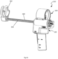
- the rear plunger assembly 250 is driveable on an elongate member 260 (in this case a threaded rod) towards and away from a stationary front support 262 of a cartridge/container.
- the motor 230 and gear assembly 240 are disposed under the rear plunger assembly 250.
- actuation of the switch 226 causes the motor 230 to drive the threaded rod 260 via the gear assembly 240.
- the elongate member 260 is an externally threaded rod coupled via the gear assembly to the motor via a lead screw nut 266 movable thereon.
- Rotation of the motor 230 drives the rear plunger assembly 260 either towards or away from the front support depending on the direction of motor rotation, in lead screw arrangement familiar to persons skilled in the art.
- the frame 265 comprising additional elongate stiffening member 264 which assists in receiving and retaining the cartridge between the rear plunger assembly 250 and the front support 262. It also helps to prevent the rear plunger assembly 250 from rotating with the elongate member 260.
- the device has a length from the front support to the end of the main housing of between 250-300mm, and optionally between 270-280 mm which does not change as the plunger moves from a retracted to extended state. More preferably, the device has a length of 278mm as shown in the Figures. Thus, the length of the device is unchanged whether the container is in the full state (as depicted in Fig 5C ) or in the empty state (as depicted in Fig 5D ).
- a quick release mechanism whereby the rear plunger assembly may be manually positioned on the elongate member 260 (threaded rod) by the user.
- the lead nut 266 is formed by a pair of split nuts 265a, 265b which have corresponding threaded profiles to the thread of the elongate member 260.
- a pair of posts 267a, b and 267c, 267d extend from the sides of each of the split nuts which are received in corresponding holes or slots formed in user actuable levers 268a, 268b.
- the split nuts are biased into engagement with each other and with the elongate member by a coil spring 270. This engagement of the split nuts with the threaded rod may be overcome by manual actuation of the levers 268a, 268b by a user urging the user actuable lever 269 in a direction of away from the elongate member 260.
- the lead screw nut 266 comprising a pair of split nuts 265a, 265b are engageable and disengageable from the externally threaded rod 260 via the user actuable lever 269.
- Figs 7A - 7D depict an exemplary rear plunger assembly, which is configured in each of the embodiments described herein to be received in the main housing above the motor and gear assembly.
- the plunger assembly comprises a rear plunger plate 52 that is mounted above a cutting edge 54 inside a housing 56. As depicted the plunger plate is supported by the cutting edge 54 which is received within a recess defined in the plunger housing 56.
- the rear plunger assembly housing is generally circular in cross section.
- the plunger assembly is accordingly adapted to be rotatably received in a corresponding circular aperture having a relatively larger diameter defined in the main housing as is shown especially in Figs 8A , 8B herein.
- the plunger housing and therefore the plunger assembly as a whole is not fixed in its orientation with respect to the main housing of the device.
- the cartridge received between the front support and rear plunger assembly is able to be rotated in situ; so as to provide the orientation of the nozzle at the front of the container desired by the user.
- this means that the orientation of the viscous material extruded by the device is easily configurable to the optimum orientation for that particular work surface; simply by manually rotating the barrel of the container.
- Fig 8A depicts a cartridge /container 80 received between the front support 63 and the rear plunger assembly 50 of a device according to either of the first or second embodiments of the present disclosure described herein. (It would be appreciated that same plunger assembly could also be used with the third embodiment described where the rear plunger assembly moves towards the front support on a threaded rod without departing from the scope of the present disclosure).
- the tip 82 of the cartridge/container has been cut by the user at an angle.
- the cutting edge 54 of the plunger assembly is essentially vertical in the exemplary orientation depicted.
- the cutting edge 54 has been urged by the movement of the front support towards the rear plunger assembly by driving the elongate member 60 via the motor 30 driving the gear assembly 40.
- the cutting edge as shown has cut into the cartridge 80; as the plunger plate 52 has urged the base of the container further into the container.
- Fig 8B depicts the same device 10 as depicted in Fig 8A , but wherein the angle of the container 80 and the plunger assembly 50 has changed by the user rotating the cartridge and assembly relative to the main housing 20. It can be seen that the cutting edge 54 is now inclined relative to the vertical axis defined by the housing due to the rotation of the container and plunger assembly 50 within the housing 20.
- the dispensing device of the present disclosure provides a precisely controlled motor driven expulsion of the viscous material from the cartridge/container selected. It would be appreciated that through careful selection of the components of the motor and gear assembly that precise control over the force on the base of the container may be achieved. In addition, the inclusion of optional friction pads which oppose motion of the elongate element in the first embodiment also enables responsive control over the expulsion of the viscous material from the dispensing device.
- the dispensing device allows for rotation of the cartridge/container relative to device such that the tip is able to be directed to whatever orientation is most suitable to the crack or work surface to which the viscous material is being applied.
- the user is able to achieve all of these orientations by rotating the container relative to the device as they wish.
- the ability to remove the elongate element to which the front support is attached and store it separately from the main device further enables the overall size of the device when not in use to be minimised. This is especially useful when storing the device in a tool box, on the way to the job site or even on a shelf between uses.
Landscapes
- Engineering & Computer Science (AREA)
- Mechanical Engineering (AREA)
- Coating Apparatus (AREA)
- Containers And Packaging Bodies Having A Special Means To Remove Contents (AREA)
Abstract
There is a provided a dispensing device for dispensing viscous material from a container received therein. The device comprises a main housing; a front support; and a rear plunger assembly spaced apart from the front support by an elongate member to receive and retain a cartridge. The rear plunger assembly comprises a plunger plate supported in a plunger housing above a cutting edge. The rear plunger assembly is rotatable about an axis parallel to the longitudinal axis of the elongate member.
A motor and a gear assembly are disposed under the rear plunger assembly in the main housing engageable with the elongate member so as to move one of the front support and plunger plate toward the other, thereby urging the cutting edge of the plunger assembly against the edge of the container as the plunger plate is driven against an end of the container to expel the viscous material therefrom.
Description
- The present disclosure relates to a hand held viscous material dispensing device.
- Cartridges or containers of viscous material such as gels, glues, caulk, silicone or sealants or pastes provide a convenient selection of materials used for filling gaps or sealing cracks in construction or maintenance projects on building sites all around the world. Application of these materials waterproof or seal around window frames, reduce the flow of heat into/out of the home, fill cracks or seal surfaces and are vital in finishing a variety of construction projects.
- Typically, material in these cartridges or containers are applied using a manually actuated or motor driven caulking gun or silicone gun. Such applicator devices expel viscous material from the cartridge through a nozzle of the cartridge into the crack or onto the work surface.
- One common arrangement of manual cartridge application tools, typically known as caulking guns, is a lever which is grasped by a user. Typically, the grasping by the user urges a plunger against one end of the cartridge which is retained in the barrel of the caulking gun, shortening the effective length of the cartridge and expelling the viscous material from the tip through a nozzle. Other arrangements may be configured so that grasping of a lever by the user drive the cartridge back against a fixed base, thereby urging viscous material from the nozzle.
- Unfortunately, such arrangements can be somewhat unwieldy and cumbersome to use, especially the first which requires a plunger which extends to a maximum of around twice the length of the cartridge or container of viscous material. The levers may also be hard to operate for users with weaker grip strength. In either arrangement, the application of pressure to the cartridge can be difficult to control, resulting in an excess or intermittent flow of viscous material onto the work surface during operation.
- Alternative arrangements of motor driven cartridge /container application devices have been devised in which a push plate and cartridge are driven relative to each other by various motorised arrangements including detachable powered drills mounted to a housing. However, such arrangements are typically relatively cumbersome and bulky; and may be difficult to operate by users to obtain the desired control over the expulsion of viscous material onto the work surface.
- Accordingly, there is a need for a hand held viscous material dispensing device which addresses or at least partially ameliorates at least some of the above problems, or at least provides the members of the public with a useful choice.
- Features and advantages of the disclosure will be set forth in the description which follows, and in part will be apparent from the description, or can be learned by practice of the herein disclosed principles. The features and advantages of the disclosure can be realized and obtained by means of the instruments and combinations particularly pointed out in the appended claims.
- In accordance with a first aspect of the present disclosure, there is provided a dispensing device for dispensing viscous material from a container received therein, said device comprising:
- a main housing;
- a front support;
- a rear plunger assembly spaced apart from the front support by an elongate member to receive and retain a container inserted therebetween, wherein said rear plunger assembly comprises a plunger plate supported in a plunger housing above a cutting edge and said assembly is rotatable about an axis parallel to the longitudinal axis of the elongate member; and
- a motor and a gear assembly disposed in the main housing, said motor and gear assembly engageable with the elongate member so as to move one of the front support and plunger plate toward the other, thereby urging the cutting edge of the plunger assembly against the edge of the container as the plunger plate is driven against an end of the container to expel the viscous material therefrom.
- The motor and gear assembly may be configured to drive the elongate member such that the front support is retracted towards the rear plunger assembly upon actuation of said motor.
- The rear plunger assembly is preferably disposed under the rear plunger assembly in the main housing.
- Advantageously the motor and gear assembly are disposed substantially within a handle shaped portion defined by the main housing.
- Preferably the rear plunger assembly housing is generally circular in cross section and is rotatably received in a corresponding circular aperture having a relatively larger diameter defined in the main housing.
- Preferably the device has a length from the front support to the end of the main housing in an extended state of between approximately 310 mm and 370 mm, and optionally between approximately 320mm and 340mm.
- Optionally the device has a length from the front support to the end of the main housing of approximately 280 mm and 340 mm, and optionally between approximately 310mm and 320mm.
- Preferably the elongate member and front support are detachable from the main housing.
- Advantageously the elongate member is a toothed rack which is driven by a pinion gear of the gear assembly upon actuation of the motor.
- The motor and gear assembly may be configured to drive the elongate member such that the rear plunger assembly is driven towards front assembly upon actuation of the motor.
- The elongate member may be an externally threaded rod coupled via the gear assembly to the motor via a lead screw nut movable thereon such that rotation of said motor drives the rear plunger assembly towards and away from the front support.
- Preferably the device has a length from front of the main housing to the end of the at least one elongate member of approximately 250mm and 300mm and optionally between 260 and 280mm.
- Advantageously, the device has a length from the front support to the end of the main housing of between 250 and 300 mm which does not change as the plunger moves from a retracted to extended state.
- Preferably the lead screw nut comprises a pair of split nuts which are engageable and disengageable from the externally threaded rod via a user actuable lever.
- In order to describe the manner in which the above-recited and other advantages and features of the disclosure can be obtained, a more particular description of the principles briefly described above will be rendered by reference to specific embodiments thereof which are illustrated in the appended Figures. Understanding that these Figures depict only exemplary embodiments of the disclosure and are not therefore to be considered to be limiting of its scope, the principles herein are described and explained with additional specificity and detail through the use of the accompanying Figures.
- Preferred embodiments of the present disclosure will be explained in further detail below by way of examples and with reference to the accompanying Figures, in which:-
-
Fig 1A depicts an exemplary perspective view of a dispensing device. -
Fig 1B depicts an exemplary perspective view of the dispensing device ofFig 1A . -
Fig 1C depicts an exemplary exploded rear perspective view of the dispensing device ofFig 1A in which the housing and motor has been removed. -
Fig 1D depicts an exemplary side view of the dispensing device ofFig 1A . -
Fig 2A depicts an exemplary perspective view of the dispensing device ofFig 1A . -
Fig 2B depicts an exemplary perspective view of the device ofFig 2A in which the main housing has been removed. -
Fig 2C (i) depicts a sectional view of the mechanism ofFig 2A . -
FIG 2C (ii) depicts a sectional view of the mechanism ofFig 2A . -
Fig 2D depicts an exemplary horizontal sectional view of a friction gripping member for opposing motion of the elongate member. -
Fig 3A depicts a side view of the dispensing device ofFig 1A in an extended state. -
Fig 3B depicts a side view of the side view of the dispensing device ofFig 1A in an extended state with a cartridge which is almost empty of viscous material received therein. -
Fig 4A depicts a perspective view of a further alternative embodiment of the dispensing device. -
Fig 4B (i) depicts a perspective view of the device ofFig 4A . -
Fig 4B (ii) depicts a perspective view of the device ofFig 4A . -
Fig 4C depicts a top view of the device ofFig 4A . -
Fig 5A depicts a perspective view of a further embodiment of a dispensing device in accordance with a present disclosure. -
Fig 5B depicts a perspective view of the dispensing device ofFig 5A in which the back cover and side covers of the main housing have been removed. -
Fig 5C depicts a side view of the dispensing device ofFig 5A in which the inserted cartridge is full of viscous material. -
Fig 5D depicts a side view of the dispensing device ofFig 5A in which the inserted cartridge has been emptied of the viscous material -
Fig 6 depicts an enlarged exploded view of an exemplary optional quick release locking mechanism by which the rear plunger assembly is engaged with the elongate member. -
Fig 7A depicts a front view of an exemplary plunger assembly in accordance with the present disclosure. -
Fig 7B depicts a perspective view of the plunger assembly depicted inFig 7A . -
Fig 7C depicts an side sectional view of the plunger assembly depicted inFig 7A . -
Fig 7D depicts an exploded view of the plunger assembly ofFig 7A . -
Fig 8A depicts an exemplary rear perspective view of the device ofFig 1A with a cartridge inserted therein and the tip in a first position. -
Fig 8B depicts an exemplary rear perspective view of the device ofFig 1A with a cartridge inserted therein and the rear plunger assembly rotated so that the tip is oriented in a second position. - Various embodiments of the disclosure are discussed in detail below. While specific implementations are discussed, it should be understood that this is done for illustration purposes only. A person skilled in the relevant art will recognize that other components and configurations may be used without departing from the spirit and scope of the disclosure.
- The disclosed technology addresses the need in the art for an improved dispensing device which is reduced in size and which provides an easy to use and control alternative to other dispensing devices.
- Referring to the
Figs 1A - 1D , there are depicted various views of the dispensing device according to a first embodiment of the present disclosure, without the cartridge or container (used interchangeably) of viscous material, for clarity purposes. - As depicted, the
device 10 includes amain housing 20 comprisingright housing 22 and lefthousing 24. Atrigger switch 26 is received between these housings, and this switch is arranged to be actuated by the users finger to provide power from the battery or power cell (not shown ) to drive themotor 30 andgear assembly 40. - The
plunger assembly 50 is received in the top of themain housing 20 above themotor 30 andgear assembly 40 as described herein. Anelongate member 60 is received in the main housing at one end. Afront support 62 is attached to the other end of theelongate member 60. - In one embodiment the
elongate member 60 is a toothed rack which is driven by apinion gear 49 of thegear assembly 40 upon actuation of themotor 30. - Typically, the
front support 62 is spaced far enough apart from therear plunger assembly 50 to receive full standard sized containers of viscous material and retain these containers with the neck of the container and base of the nozzle resting in thefront support 62, whilst the base of the container contacts theplunger assembly 50. - Advantageously, as depicted, the rear plunger is disposed in the main housing. As can be seen especially with reference to
Figs 1C and1D , themotor 30 andgear assembly 40 are disposed substantially within the handle shaped portion of the main housing. - As depicted, in an exemplary arrangement the
gear assembly 40 comprises a four layers of planetary gears, a first layer ofplanetary gears 42a, a second layer of planetary gears 44b, a third layer ofplanetary gears 42c and a fourth layer ofplanetary gears 42d. - As can be also seen in
Figure 1C , andFigs 7A - 7C , theplunger assembly 50 comprises aplunger plate 52 supported by acutting edge 54 in ahousing 56. - As is described further herein, in the embodiment depicted the actuation of the
motor 30 by the user activating thetrigger 26 retracts thefront support 62 of theelongate member 60 towards therear plunger assembly 50. Teeth ofspur gear 49 mesh with correspondingteeth 64 of theelongate member 60, changing the rotational motion of thegear assembly 40 into linear motion of theelongate member 60. As is known to persons skilled in the art, changing the direction of rotation of the motor will change the direction of travel of theelongate member 60 relative to the housing. - The
rear plunger assembly 50 is thus urged against an end or base of the container, which drives theplunger plate 52 inside the container toward the nozzle and thereby extrudes the viscous material in the container onto the work surface. - In each of the embodiments described herein, as the front support and rear plunger assembly are driven towards each other, the rear plunger assembly is arranged to cut into the side of the container. In the first and second embodiments, the cutting of the container by the rear plunger assembly enables the front support to be retracted towards the rear plunger assembly as the elongate member is driven via the gear assembly by the motor. In the third embodiment described herein the rear plunger assembly is driven via the gear assembly by the motor toward the front support.
- As depicted in
Figs 2A - 2D , in an optional arrangement, thedevice 10 may be configured such that theelongate member 60 may be disengaged from thehousing 20. This further assists in reducing the size taken up the dispensing device when stored. As depicted, the user actuates adisengagement button 25 and then pulls theelongate member 60 to release it. - As can be seen, particularly in
Fig 2C (i) , theelongate member 60 cannot be pulled out from the main housing as thepin 48 is engaged with the end of theelongate member 60. Upon actuation of thedisengagement button 25 by the user, this button pivots within the housing and lifts thepin 48 out from engagement with the end of theelongate member 60 as shown inFig 2C(ii) . This means that theelongate member 60 can then be removed from the housing as depicted inFig 2B . - As depicted in
Fig 2D , arubber rod 27 may further be disposed in the housing and arranged to bear against theelongate member 60. This rod is depicted in storage configuration in the figure, but it would be appreciated that this rod is configured to provide frictional engagement of the elongate member and prevent it moving backwards and forwards during normal operation too easily relative to the main housing. - Advantageously, as depicted in
Fig 3A , the length of the device can be configured so that the length from the front support to the end of the main housing in an extended state of between 330mm -350mm. An exemplary full container ofviscous material 80 is shown for reference, received between therear plunger assembly 50 and the front support member with thenozzle 82 protruding forwards. It would be appreciated that length of the elongate member and/or the physical size parameters of the housing may be selected so as to provide these dimensions. In the Figure depicted the length is 338mm, but it would be appreciated that other sizes in the range of 280mm - 370mm could also be selected, and more preferably 300-350mm. - Preferably, as depicted in
Fig 3B , in the retracted state shown where thecontainer 80 is empty of viscous material, the length from front of the main housing to the end of the at least one elongate member is approximately 240mm - 300mm, and preferably 260 mm-280mm. More particularly, in the embodiment depicted the length is 270mm. - In a further embodiment of the present disclosure, there is depicted in
Fig 4A - Fig 4C a smaller version of the first embodiment of thedevice 110 described herein in which thefront support 162 is also moveable towards and away from therear plunger assembly 150. As depicted, thefront support 162 is spaced apart from themain housing 120 byelongate member 160. Preferably, theelongate member 160 is a toothed rack which is driven byspur gear 149 of thegear assembly 140 upon actuation of themotor 130. - A
rear plunger assembly 150 is disposed in themain housing 120, above themotor 130 andgear assembly 140 which in this embodiment is small enough such that it is substantially disposed in the handle under therear plunger assembly 150. It would be appreciated that a user can grip the housing with their fingers. Layers ofplanetary gears motor 130. These mesh with further layers ofplanetary gears drive spur gear 49 to mesh with the teeth of the elongate member in a rack and pinion type arrangement. - As shown in
Fig 4C , preferably the device has a length from the front support to the end of the main housing of approximately 280mm-340mm, and optionally between 300-320 mm, and more particularly in an exemplary arrangement this length is 312mm. - In a third embodiment of the
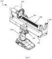
device 210 depicted inFigs 5A - 5D , therear plunger assembly 250 is driveable on an elongate member 260 (in this case a threaded rod) towards and away from astationary front support 262 of a cartridge/container. - The motor 230 and
gear assembly 240 are disposed under therear plunger assembly 250. In this embodiment, actuation of theswitch 226 causes the motor 230 to drive the threadedrod 260 via thegear assembly 240. Advantageously, theelongate member 260 is an externally threaded rod coupled via the gear assembly to the motor via alead screw nut 266 movable thereon. Rotation of the motor 230 drives therear plunger assembly 260 either towards or away from the front support depending on the direction of motor rotation, in lead screw arrangement familiar to persons skilled in the art. - In this embodiment the
frame 265 comprising additional elongate stiffeningmember 264 which assists in receiving and retaining the cartridge between therear plunger assembly 250 and thefront support 262. It also helps to prevent therear plunger assembly 250 from rotating with theelongate member 260. - As depicted in
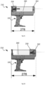
Fig 5C, and Fig 5D in an exemplary embodiment, the device has a length from the front support to the end of the main housing of between 250-300mm, and optionally between 270-280 mm which does not change as the plunger moves from a retracted to extended state. More preferably, the device has a length of 278mm as shown in the Figures. Thus, the length of the device is unchanged whether the container is in the full state (as depicted inFig 5C ) or in the empty state (as depicted inFig 5D ). - In a further aspect of the third embodiment depicted in
Fig 6 , there is depicted an exemplary quick release mechanism whereby the rear plunger assembly may be manually positioned on the elongate member 260 (threaded rod) by the user. - As shown, the
lead nut 266 is formed by a pair ofsplit nuts elongate member 260. A pair ofposts 267a, b and 267c, 267d (not shown) extend from the sides of each of the split nuts which are received in corresponding holes or slots formed inuser actuable levers coil spring 270. This engagement of the split nuts with the threaded rod may be overcome by manual actuation of thelevers user actuable lever 269 in a direction of away from theelongate member 260. - Accordingly, the
lead screw nut 266 comprising a pair ofsplit nuts rod 260 via theuser actuable lever 269. -
Figs 7A - 7D depict an exemplary rear plunger assembly, which is configured in each of the embodiments described herein to be received in the main housing above the motor and gear assembly. - As depicted, the plunger assembly comprises a
rear plunger plate 52 that is mounted above acutting edge 54 inside ahousing 56. As depicted the plunger plate is supported by thecutting edge 54 which is received within a recess defined in theplunger housing 56. - Advantageously, as shown the rear plunger assembly housing is generally circular in cross section. The plunger assembly is accordingly adapted to be rotatably received in a corresponding circular aperture having a relatively larger diameter defined in the main housing as is shown especially in
Figs 8A ,8B herein. This means that the plunger housing and therefore the plunger assembly as a whole is not fixed in its orientation with respect to the main housing of the device. As such, the cartridge received between the front support and rear plunger assembly is able to be rotated in situ; so as to provide the orientation of the nozzle at the front of the container desired by the user. In turn, this means that the orientation of the viscous material extruded by the device is easily configurable to the optimum orientation for that particular work surface; simply by manually rotating the barrel of the container. -
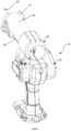
Fig 8A depicts a cartridge /container 80 received between the front support 63 and therear plunger assembly 50 of a device according to either of the first or second embodiments of the present disclosure described herein. (It would be appreciated that same plunger assembly could also be used with the third embodiment described where the rear plunger assembly moves towards the front support on a threaded rod without departing from the scope of the present disclosure). - As depicted in
Fig 8A , thetip 82 of the cartridge/container has been cut by the user at an angle. Thecutting edge 54 of the plunger assembly is essentially vertical in the exemplary orientation depicted. Thecutting edge 54 has been urged by the movement of the front support towards the rear plunger assembly by driving theelongate member 60 via themotor 30 driving thegear assembly 40. The cutting edge as shown has cut into thecartridge 80; as theplunger plate 52 has urged the base of the container further into the container. -
Fig 8B depicts thesame device 10 as depicted inFig 8A , but wherein the angle of thecontainer 80 and theplunger assembly 50 has changed by the user rotating the cartridge and assembly relative to themain housing 20. It can be seen that thecutting edge 54 is now inclined relative to the vertical axis defined by the housing due to the rotation of the container andplunger assembly 50 within thehousing 20. - The above embodiments are described by way of example only. Many variations are possible without departing from the scope of the disclosure as defined in the appended claims.
- Advantageously, the dispensing device of the present disclosure provides a precisely controlled motor driven expulsion of the viscous material from the cartridge/container selected. It would be appreciated that through careful selection of the components of the motor and gear assembly that precise control over the force on the base of the container may be achieved. In addition, the inclusion of optional friction pads which oppose motion of the elongate element in the first embodiment also enables responsive control over the expulsion of the viscous material from the dispensing device.
- Further, the dispensing device allows for rotation of the cartridge/container relative to device such that the tip is able to be directed to whatever orientation is most suitable to the crack or work surface to which the viscous material is being applied. In some uses, it may be preferable for the tip (usually cut any an angle) to be orientated with the shortest part of the inclined tip face proximate to the work surface, whereas in other uses it may be preferable for the shortest part of the tip face to be oriented to either side or even upwards. When using the device of the present disclosure the user is able to achieve all of these orientations by rotating the container relative to the device as they wish.
- In the first and second embodiment of the present disclosure, the ability to remove the elongate element to which the front support is attached and store it separately from the main device further enables the overall size of the device when not in use to be minimised. This is especially useful when storing the device in a tool box, on the way to the job site or even on a shelf between uses.
- Although a variety of examples and other information was used to explain aspects within the scope of the appended claims, no limitation of the claims should be implied based on particular features or arrangements in such examples, as one of ordinary skill would be able to use these examples to derive a wide variety of implementations. Further and although some subject matter may have been described in language specific to examples of structural features and/or method steps, it is to be understood that the subject matter defined in the appended claims is not necessarily limited to these described features or acts. For example, such functionality can be distributed differently or performed in components other than those identified herein. Rather, the described features and steps are disclosed as examples of components of systems and methods within the scope of the appended claims.
Claims (14)
- A dispensing device for dispensing viscous material from a container received therein, said device comprising:a main housing;a front support;a rear plunger assembly spaced apart from the front support by an elongate member to receive and retain a cartridge inserted therebetween, wherein said rear plunger assembly comprises a plunger plate supported in a plunger housing above a cutting edge and said assembly is rotatable about an axis parallel to the longitudinal axis of the elongate member; anda motor and a gear assembly disposed in the main housing, said motor and gear assembly engageable with the elongate member so as to move one of the front support and the rear plunger assembly toward each other, thereby urging the cutting edge of the rear plunger assembly against the edge of the container as the plunger plate is driven against an end of the container to expel the viscous material therefrom.
- The dispensing device according to claim 1 wherein the motor and gear assembly is configured to drive the elongate member such that the front support is retracted towards the rear plunger assembly upon actuation of said motor.
- The dispensing device according to claim 1 or claim 2 wherein the rear plunger assembly is disposed in the main housing.
- The dispensing device according to claim 1 wherein the motor and gear assembly are disposed under the rear plunger assembly and substantially within a handle shaped portion defined by the main housing.
- The dispensing device according to any one of the preceding claims wherein the rear plunger assembly housing is generally circular in cross section and is rotatably received in a corresponding circular aperture having a relatively larger diameter defined in the main housing.
- The dispensing device according to claim 1 wherein the device has a length from the front support to the end of the main housing in an extended state of approximately between 310 mm and 360 mm, and preferably approximately between 320 mm and 340 mm.
- The dispensing device according to claim 1 wherein the device has a length from the front support to the end of the main housing of approximately 280 mm and 340 mm, and preferably approximately between 310mm and 320mm.
- The dispensing device according to claim 1 wherein the elongate member and the front support are detachable from the main housing.
- The dispensing device according to claim 1 wherein the elongate member is a toothed rack which is driven by a pinion gear of the gear assembly upon actuation of the motor.
- The dispensing device according to claim 1 wherein the motor and gear assembly are configured to drive the elongate member such that the rear plunger assembly is driven towards front assembly upon actuation of the motor.
- The dispensing device according to claim 1 or claim 10 wherein the elongate member is an externally threaded rod coupled via the gear assembly to the motor via a lead screw nut movable thereon such that rotation of said motor drives the rear plunger assembly towards and away from the front support.
- The dispensing device according to claim 1 or claim 10 or claim 11, wherein the dispensing device has a length from front of the main housing to the end of the at least one elongate member of approximately 250mm and 300mm and preferably between 260mm and 280mm in the retracted state.
- The dispensing device according to claim 1 or any one of claims 10 to claim 12 wherein the device has a length from the front support to the end of the main housing of between 250 mm and 300 mm.
- The dispensing device according to claim 10 wherein the lead screw nut comprises a pair of split nuts which are engageable and disengageable from the externally threaded rod via a user actuable lever.
Applications Claiming Priority (1)
| Application Number | Priority Date | Filing Date | Title |
|---|---|---|---|
| HK22023077786.8A HK20089219A1 (en) | 2023-08-18 | Motor operated dispensing device with cutting blade |
Publications (1)
| Publication Number | Publication Date |
|---|---|
| EP4516411A1 true EP4516411A1 (en) | 2025-03-05 |
Family
ID=94478352
Family Applications (1)
| Application Number | Title | Priority Date | Filing Date |
|---|---|---|---|
| EP24194354.7A Pending EP4516411A1 (en) | 2023-08-18 | 2024-08-13 | Motor operated dispensing device with cutting blade |
Country Status (5)
| Country | Link |
|---|---|
| US (1) | US20250058348A1 (en) |
| EP (1) | EP4516411A1 (en) |
| CN (1) | CN119489020A (en) |
| AU (1) | AU2024205719A1 (en) |
| DE (1) | DE202024002596U1 (en) |
Citations (2)
| Publication number | Priority date | Publication date | Assignee | Title |
|---|---|---|---|---|
| JPS63185475A (en) * | 1987-01-28 | 1988-08-01 | Wakai Sangyo Kk | Cartridge gun |
| US20020108971A1 (en) * | 2001-02-12 | 2002-08-15 | Luc Lafond | Motor operated caulking gun |
Family Cites Families (7)
| Publication number | Priority date | Publication date | Assignee | Title |
|---|---|---|---|---|
| JPS59222251A (en) * | 1983-05-31 | 1984-12-13 | Matsushita Electric Works Ltd | Motor type extruder for viscous material |
| JPS61222569A (en) * | 1985-03-28 | 1986-10-03 | Matsushita Electric Works Ltd | Extruder for viscous agent |
| US5503307A (en) * | 1995-03-08 | 1996-04-02 | Wilson; Steven J. | Quick release automatic electric caulking gun |
| US20080006654A1 (en) * | 2006-07-07 | 2008-01-10 | Lampe John K | Caulk gun with cutter |
| US7883033B2 (en) * | 2007-12-10 | 2011-02-08 | Battelle Memorial Institute | Lead screw locking device |
| US9205451B2 (en) * | 2010-04-22 | 2015-12-08 | Wadeeh Zahr | Material dispensing system |
| US10640280B2 (en) * | 2017-04-05 | 2020-05-05 | Meritool Llc | Trigger assembly and method of operation |
-
2024
- 2024-08-13 DE DE202024002596.9U patent/DE202024002596U1/en active Active
- 2024-08-13 AU AU2024205719A patent/AU2024205719A1/en active Pending
- 2024-08-13 US US18/802,832 patent/US20250058348A1/en active Pending
- 2024-08-13 EP EP24194354.7A patent/EP4516411A1/en active Pending
- 2024-08-14 CN CN202411115713.2A patent/CN119489020A/en active Pending
Patent Citations (2)
| Publication number | Priority date | Publication date | Assignee | Title |
|---|---|---|---|---|
| JPS63185475A (en) * | 1987-01-28 | 1988-08-01 | Wakai Sangyo Kk | Cartridge gun |
| US20020108971A1 (en) * | 2001-02-12 | 2002-08-15 | Luc Lafond | Motor operated caulking gun |
Also Published As
| Publication number | Publication date |
|---|---|
| AU2024205719A1 (en) | 2025-03-06 |
| US20250058348A1 (en) | 2025-02-20 |
| CN119489020A (en) | 2025-02-21 |
| DE202024002596U1 (en) | 2025-09-12 |
Similar Documents
| Publication | Publication Date | Title |
|---|---|---|
| US10864540B2 (en) | Material dispenser control assembly | |
| US4986454A (en) | Portable dispenser for viscous material | |
| US5909830A (en) | Electrically operated material dispensing gun and method | |
| US5375740A (en) | Manual dispenser for dispensing predetermined amounts of viscous material through actuation of a trigger | |
| US5503307A (en) | Quick release automatic electric caulking gun | |
| US5141348A (en) | Paste wax applicator | |
| GB2172933A (en) | Dispensing gun | |
| KR20030090632A (en) | Fluid dispenser | |
| US6089412A (en) | Multipurpose dispenser system | |
| WO2004075851A2 (en) | Multiple use dental viscous material dispenser | |
| AU2024205719A1 (en) | Motor operated dispensing device with cutting blade | |
| CN106361454B (en) | Portable medicine pushing device | |
| JP2011156493A (en) | Caulking gun | |
| US20190217330A1 (en) | Glue gun device | |
| US6945436B2 (en) | Dispenser for limiting material extruded after actuation | |
| WO2007144434A1 (en) | Disposable dispensing device | |
| JPH0977151A (en) | Paste extrusion equipment | |
| JPH0580563U (en) | Viscous liquid extruder | |
| KR101300535B1 (en) | Quick-loading electric silicone gun | |
| US9205451B2 (en) | Material dispensing system | |
| JPH0561921B2 (en) | ||
| JP2001252602A (en) | Electric tool | |
| CN117693640A (en) | Drive mechanism and viscous material dispensing gun | |
| JP2005097961A (en) | Sealing gun | |
| JP3558760B2 (en) | Discharge device |
Legal Events
| Date | Code | Title | Description |
|---|---|---|---|
| PUAI | Public reference made under article 153(3) epc to a published international application that has entered the european phase |
Free format text: ORIGINAL CODE: 0009012 |
|
| STAA | Information on the status of an ep patent application or granted ep patent |
Free format text: STATUS: THE APPLICATION HAS BEEN PUBLISHED |
|
| AK | Designated contracting states |
Kind code of ref document: A1 Designated state(s): AL AT BE BG CH CY CZ DE DK EE ES FI FR GB GR HR HU IE IS IT LI LT LU LV MC ME MK MT NL NO PL PT RO RS SE SI SK SM TR |
|
| STAA | Information on the status of an ep patent application or granted ep patent |
Free format text: STATUS: REQUEST FOR EXAMINATION WAS MADE |
|
| 17P | Request for examination filed |
Effective date: 20250902 |