EP4516378A2 - Filtration element with gradient seal interface - Google Patents
Filtration element with gradient seal interface Download PDFInfo
- Publication number
- EP4516378A2 EP4516378A2 EP25152184.5A EP25152184A EP4516378A2 EP 4516378 A2 EP4516378 A2 EP 4516378A2 EP 25152184 A EP25152184 A EP 25152184A EP 4516378 A2 EP4516378 A2 EP 4516378A2
- Authority
- EP
- European Patent Office
- Prior art keywords
- filter cartridge
- endcap
- skirt
- filter
- interface
- Prior art date
- Legal status (The legal status is an assumption and is not a legal conclusion. Google has not performed a legal analysis and makes no representation as to the accuracy of the status listed.)
- Pending
Links
Images







Classifications
-
- F—MECHANICAL ENGINEERING; LIGHTING; HEATING; WEAPONS; BLASTING
- F01—MACHINES OR ENGINES IN GENERAL; ENGINE PLANTS IN GENERAL; STEAM ENGINES
- F01M—LUBRICATING OF MACHINES OR ENGINES IN GENERAL; LUBRICATING INTERNAL COMBUSTION ENGINES; CRANKCASE VENTILATING
- F01M11/00—Component parts, details or accessories, not provided for in, or of interest apart from, groups F01M1/00 - F01M9/00
- F01M11/03—Mounting or connecting of lubricant purifying means relative to the machine or engine; Details of lubricant purifying means
-
- B—PERFORMING OPERATIONS; TRANSPORTING
- B01—PHYSICAL OR CHEMICAL PROCESSES OR APPARATUS IN GENERAL
- B01D—SEPARATION
- B01D29/00—Filters with filtering elements stationary during filtration, e.g. pressure or suction filters, not covered by groups B01D24/00 - B01D27/00; Filtering elements therefor
- B01D29/11—Filters with filtering elements stationary during filtration, e.g. pressure or suction filters, not covered by groups B01D24/00 - B01D27/00; Filtering elements therefor with bag, cage, hose, tube, sleeve or like filtering elements
- B01D29/13—Supported filter elements
- B01D29/15—Supported filter elements arranged for inward flow filtration
- B01D29/21—Supported filter elements arranged for inward flow filtration with corrugated, folded or wound sheets
-
- B—PERFORMING OPERATIONS; TRANSPORTING
- B01—PHYSICAL OR CHEMICAL PROCESSES OR APPARATUS IN GENERAL
- B01D—SEPARATION
- B01D27/00—Cartridge filters of the throw-away type
- B01D27/08—Construction of the casing
-
- B—PERFORMING OPERATIONS; TRANSPORTING
- B01—PHYSICAL OR CHEMICAL PROCESSES OR APPARATUS IN GENERAL
- B01D—SEPARATION
- B01D35/00—Filtering devices having features not specifically covered by groups B01D24/00 - B01D33/00, or for applications not specifically covered by groups B01D24/00 - B01D33/00; Auxiliary devices for filtration; Filter housing constructions
- B01D35/14—Safety devices specially adapted for filtration; Devices for indicating clogging
- B01D35/147—Bypass or safety valves
-
- B—PERFORMING OPERATIONS; TRANSPORTING
- B01—PHYSICAL OR CHEMICAL PROCESSES OR APPARATUS IN GENERAL
- B01D—SEPARATION
- B01D35/00—Filtering devices having features not specifically covered by groups B01D24/00 - B01D33/00, or for applications not specifically covered by groups B01D24/00 - B01D33/00; Auxiliary devices for filtration; Filter housing constructions
- B01D35/30—Filter housing constructions
-
- B—PERFORMING OPERATIONS; TRANSPORTING
- B01—PHYSICAL OR CHEMICAL PROCESSES OR APPARATUS IN GENERAL
- B01D—SEPARATION
- B01D2201/00—Details relating to filtering apparatus
- B01D2201/29—Filter cartridge constructions
- B01D2201/291—End caps
- B01D2201/295—End caps with projections extending in a radial outward direction, e.g. for use as a guide, spacing means
-
- B—PERFORMING OPERATIONS; TRANSPORTING
- B01—PHYSICAL OR CHEMICAL PROCESSES OR APPARATUS IN GENERAL
- B01D—SEPARATION
- B01D2201/00—Details relating to filtering apparatus
- B01D2201/30—Filter housing constructions
- B01D2201/301—Details of removable closures, lids, caps, filter heads
- B01D2201/302—Details of removable closures, lids, caps, filter heads having inlet or outlet ports
-
- B—PERFORMING OPERATIONS; TRANSPORTING
- B01—PHYSICAL OR CHEMICAL PROCESSES OR APPARATUS IN GENERAL
- B01D—SEPARATION
- B01D2201/00—Details relating to filtering apparatus
- B01D2201/30—Filter housing constructions
- B01D2201/301—Details of removable closures, lids, caps, filter heads
- B01D2201/304—Seals or gaskets
-
- B—PERFORMING OPERATIONS; TRANSPORTING
- B01—PHYSICAL OR CHEMICAL PROCESSES OR APPARATUS IN GENERAL
- B01D—SEPARATION
- B01D2201/00—Details relating to filtering apparatus
- B01D2201/34—Seals or gaskets for filtering elements
-
- B—PERFORMING OPERATIONS; TRANSPORTING
- B01—PHYSICAL OR CHEMICAL PROCESSES OR APPARATUS IN GENERAL
- B01D—SEPARATION
- B01D2201/00—Details relating to filtering apparatus
- B01D2201/40—Special measures for connecting different parts of the filter
- B01D2201/4007—Use of cam or ramp systems
-
- B—PERFORMING OPERATIONS; TRANSPORTING
- B01—PHYSICAL OR CHEMICAL PROCESSES OR APPARATUS IN GENERAL
- B01D—SEPARATION
- B01D2201/00—Details relating to filtering apparatus
- B01D2201/40—Special measures for connecting different parts of the filter
- B01D2201/4076—Anti-rotational means
-
- F—MECHANICAL ENGINEERING; LIGHTING; HEATING; WEAPONS; BLASTING
- F01—MACHINES OR ENGINES IN GENERAL; ENGINE PLANTS IN GENERAL; STEAM ENGINES
- F01M—LUBRICATING OF MACHINES OR ENGINES IN GENERAL; LUBRICATING INTERNAL COMBUSTION ENGINES; CRANKCASE VENTILATING
- F01M11/00—Component parts, details or accessories, not provided for in, or of interest apart from, groups F01M1/00 - F01M9/00
- F01M11/03—Mounting or connecting of lubricant purifying means relative to the machine or engine; Details of lubricant purifying means
- F01M2011/031—Mounting or connecting of lubricant purifying means relative to the machine or engine; Details of lubricant purifying means characterised by mounting means
Definitions
- the present application relates generally to liquid filtration systems for internal combustion engine systems.
- an amount of particulate contamination in liquids used to power and lubricate an internal combustion engine can be reduced by passing the liquids through a filter element or cartridge, which captures solid particles entrained within the fluid.
- the structure of the cartridge and the materials used in the construction of the cartridge are carefully controlled by an original equipment manufacturer (OEM) in order to prevent damage to the engine and to ensure optimal engine performance.
- OEM original equipment manufacturer
- a user may choose to replace the filter cartridge with a non-genuine (aftermarket) filter cartridge that is not produced by the OEM.
- the non-genuine filter cartridge may not adequately remove particulate contamination from the liquid which can, over a period of time, result in damage to the internal combustion engine.
- a liquid filtration system in one set of embodiments, includes a filter head, a shell housing, and a filter cartridge.
- the filter head includes a skirt having a ramp disposed at a first end of the skirt.
- the shell housing is coupled to the filter head.
- the filter cartridge is disposed within the shell housing.
- the filter cartridge includes a filter media pack and an endcap coupled to a first end of the filter media pack.
- the endcap includes an interface member extending from an upper surface of the endcap.
- the interface member includes a sealing member that is at least partially tilted at an oblique angle relative to a central axis of the endcap. The sealing member is sealingly engaged with the skirt.
- a liquid filter cartridge in another set of embodiments, includes a filter media pack and an endcap.
- the endcap is coupled to a first end of the filter media pack.
- the endcap includes an interface member that extends from an upper surface of the endcap.
- the interface member includes a sealing member that is at least partially tilted at an oblique angle with respect to a central axis of the filter media pack.
- Unfiltered fuel may include dirt, metal particles, and other solid contaminants that can damage fuel injectors and other engine components.
- fuel filtration systems which filter the fuel to remove any solid materials before passing the fuel to the injectors.
- the filtration system may include a shell housing, a filter head, and a filter cartridge. In operation, the filtration system directs the fuel through the filter cartridge, which includes a media that captures any solid particulate entrained in the fuel.
- the performance of the filtration system depends, among other factors, on the structure of the filter cartridge and the materials used to construct the filter cartridge (e.g., the materials used to produce a filter media for the filter cartridge, the specifications of the filter media pack such as the flow area of the filter media pack, the pleat depth of the filter media pack, and other factors).
- the materials used to construct the filter cartridge e.g., the materials used to produce a filter media for the filter cartridge, the specifications of the filter media pack such as the flow area of the filter media pack, the pleat depth of the filter media pack, and other factors.
- accumulated particulate on the filter cartridge can increase the pressure drop across the filter cartridge (and, correspondingly, a pressure drop across a fuel delivery system for the engine).
- the filter cartridge can be removed from the filtration system and replaced with a clean filter cartridge.
- a user may elect to replace the filter cartridge with a non-genuine (aftermarket) filter cartridge; for example, in order to reduce maintenance costs.
- the filtration performance of the aftermarket filter cartridges can be much lower than an OEM filter cartridge. Over time, operating with the aftermarket filter cartridge may result in damage to the injectors and/or other parts of the engine, thereby leading to a reduction in engine performance.
- Implementations herein relate to methods and systems including a unique sealing interface between a filter cartridge and a filter head.
- the sealing interface includes a sealing member (e.g., O-ring, etc.) extending in a plane that is tilted at an oblique angle relative to a central axis (e.g., longitudinal axis) of the filter cartridge.
- the sealing member engages a skirt on the filter head at a fixed orientation relative to the skirt to form a seal between sealing member and the skirt.
- the sealing interface additionally includes an anti-rotation member, which engages (e.g., contacts) a leading edge of the ramped skirt to reorient the filter cartridge into alignment relative to a sealing interface on the filter head.
- Implementations herein also relate to a filter head that includes a plurality of vertical ribs and/or a plurality of indentations (e.g., grooves) that restrict the use of non-matching, non-genuine filter cartridges including planar radial seals.
- Figure 1 is a perspective view of a first example liquid filtration system, shown as system 100.
- the system 100 may be used to filter a fluid provided to an internal combustion engine.
- the fluid may be a fuel, an engine oil, a hydraulic oil, or another lubricant.
- the system 100 is a fuel filtration system for a diesel engine that uses diesel fuel to drive the combustion process.
- the system 100 is configured to be mounted on the diesel engine. In other embodiments, the system 100 may be configured to be mounted remotely from the engine (e.g., on a vehicle chassis, etc.).
- the system 100 includes a filter cartridge 200, a filter head 300, and a shell housing 400.
- the filter cartridge 200 is disposed within a hollow portion 402 of the shell housing 400 and is coaxial with respect to a central axis 404 of the shell housing 400.
- the filter cartridge 200 is a cylindrically-shaped cartridge having a cylindrically-shaped filter pack 202.
- the filter pack 202 includes a filter media 204 configured to filter particulate matter from a fluid flowing therethrough so as to produce filtered fluid (e.g., clean fluid).
- the filter media 204 may include a porous material having a predetermined pore size.
- the filter media 204 may include a paper-based filter media, a fiber-based filter media, a foam-based filter media, or the like.
- the filter media 204 may be pleated or formed into another desired shape to increase a flow area through the filter pack 202, or to otherwise alter the particle removal efficiency of the filter cartridge 200.
- the filter cartridge 200 may be arranged as an outside-in flow filter cartridge having an outer dirty side and an inner clean side. In an alternative arrangement, the filter cartridge 200 is an inside-out filter cartridge having an inner dirty side and an outer clean side. Fluid to be filtered passes from the dirty side of the filter cartridge 200 to the clean side of the filter cartridge 200.
- the filter pack 202 defines a central opening 206 extending along a central axis 210 (e.g., a longitudinal axis, up and down as shown in Figure 1 ) of the filter cartridge 200.
- the central opening 206 is sized to receive a center support tube 208 therein.
- the support tube 208 extends longitudinally along at least a portion of the central opening 206 from a first, upper end 212 of the filter cartridge 200 to a second, bottom end 214 of the filter cartridge 200.
- the support tube 208 is formed in the shape of a hollow cylinder.
- An outer wall of the support tube 208 is perforated in order to allow fluid to pass through the support tube 208.
- the shell housing 400 defines a hollow portion 402 having an inner cross-sectional diameter within which the filter cartridge 200 is positioned.
- the shell housing 400 e.g., a filter housing, container, or reservoir
- the shell housing 400 includes a lower wall 406 and a sidewall 408 extending upwardly from the lower wall 406 in substantially perpendicular orientation relative to the lower wall 406.
- the shell housing 400 may be formed form a strong and rigid material.
- the shell housing 400 may be formed from a plastic material (e.g., polypropylene, high density polyethylene, polyvinyl chloride, nylon, etc.), a metal (e.g., aluminum, stainless steel, etc.), or another suitable material.
- the cross-sectional shape of the shell housing 400 may be the same or similar to the cross-sectional shape of the filter cartridge 200. As shown in Figure 1 , the shell housing 400 is formed in the shape of a cylinder such that the shell housing 400 has a generally circular cross-section normal to the central axis 404 of the shell housing 400. In other embodiments, the shell housing 400 may have any other suitable cross-sectional shape; for example, circular, oval, rectangular, or another suitable shape.
- the shell housing 400 is threadably coupled to the filter head 300.
- the shell housing 400 includes a male threaded portion 410 disposed on an outer surface 414 of the shell housing 400 and extending downwardly (e.g., parallel to the central axis 404 of the shell housing 400) from a first, upper end 416 of the shell housing 400.
- the male threaded portion 410 is engaged with a female threaded portion 302 of the filter head 300.
- the female threaded portion 302 is disposed on an inner surface 304 of an outer flange 306 of the filter head 300 such that, in an installed position (as shown in Figure 1 ), the outer flange 306 at least partially surrounds the shell housing 400.
- the shell housing 400 and/or the filter head 300 may include one or more sealing mechanisms to prevent fluid from leaking into an environment surrounding the system 100.
- the shell housing 400 includes a radial sealing member 412 (e.g., an O-ring, etc.) that presses against the inner surface 304 of the outer flange 306 proximate to a lower edge 308 of the outer flange 306.
- a radial sealing member 412 e.g., an O-ring, etc.
- the filter cartridge 200 is structured to detachably (e.g., removably) couple to the shell housing 400 and the filter head 300.
- the filter cartridge 200 includes a first endcap 216 coupled to the first end 212 of the filter cartridge 200 and a second endcap 218 coupled to the second end 214 of the filter cartridge 200.
- the first endcap 216 and the second endcap 218 may be coupled to the filter pack 202 using glue or another suitable bonding agent (e.g., adhesive product) in order to seal the first end 212 and the second end 214 of the filter pack 202 and to prevent dirty fluid from bypassing the filter media 204 through the first end 212 and the second end 214.
- Figures 2 and 3 show side cross-sectional views of the system 100 at 1) an interface between the first endcap 216 and the filter head 300 ( Figure 2), and 2 ) an interface between the second endcap 218 and the shell housing 400 ( Figure 3 ).
- the first endcap 216 includes an interface member 220 structured to engage with the filter head 300 in order to fluidly couple the filter cartridge 200 to the filter head 300.
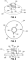
- Figures 4-6 show perspective, side, and top views, respectively, of the first endcap 216 of the filter cartridge 200.
- the interface member 220 includes a generally cylindrically-shaped protrusion 222 extending from an upper surface 224 of a base 226 of the first endcap 216.
- the protrusion 222 extends upwardly (e.g., vertically upwards as shown in Figure 6 ) from the upper surface 224 in substantially perpendicular orientation relative to the upper surface 224.
- the protrusion 222 defines a central opening, shown as through-hole 228 that extends through the first endcap 216. As shown in Figure 2 , the through-hole 228 is axially aligned (in coaxial arrangement) with the central opening 206 of the filter cartridge 200 and a central axis 310 of the filter head 300.
- the interface member 220 engages the filter head 300 along an angled sealing interface 309.
- the orientation of the sealing interface 309 prevents the use of non-genuine filter cartridges that rely on planar radial sealing elements (e.g., sealing elements that extend normal to the central axis 210 of the filter cartridge 200).
- the interface member 220 additionally includes a sealing member 230 (e.g., an O-ring, etc.) that is sealingly engaged with the filter head 300 in order to prevent fluid bypass between the interface member 220 and the filter head 300.
- the sealing member 230 is tilted at an oblique angle 232 (e.g., an angle other than 90°) with respect to the central axis 210 of the filter cartridge 200 such that a cross-section through the sealing member 230 forms an ellipse.
- an oblique angle 232 e.g., an angle other than 90°
- the oblique angle 232 may be approximately 75° or within a range between approximately 50°-85°. In other embodiments, the oblique angle 232 may be within different ranges.
- the first endcap 216 of the filter cartridge 200 includes an upper extension piece 234 and a lower extension piece 236 that each extend radially outward from the cylindrically-shaped protrusion 222.
- the lower extension piece 236 that is parallel (or substantially parallel) to the upper extension piece 234.
- the lower extension piece 236 is spaced apart from the upper extension piece 234.
- the upper extension piece 234 and the lower extension piece 236 form a groove 238 structured (e.g., sized) to receive the sealing member 230 therein.
- the groove 238 is sized to prevent movement of the sealing member 230 relative to first endcap 216 and the protrusion 222.
- an upper edge 240 of the upper extension piece 234 is approximately coplanar (e.g., flush) with an upper surface 242 (e.g., upper end, upper edge, etc.) of the protrusion 222.
- the first endcap 216 includes an anti-rotation member 244 structured to engage with the filter head 300 in order to position the sealing member 230 (see also Figure 2 ) along the sealing interface 309.
- the anti-rotation member 244 includes a generally rectangular-shaped tab 246 disposed along an outer surface 248 of the protrusion 222.
- the tab 246 engages the interface member 220 (e.g., the protrusion 222), and extends radially away from the interface member 220 such that there is no gap between the anti-rotation member 244 and the interface member 220.
- the tab 246 is a separate component from the interface member 220 and contacts (e.g., is disposed on) the interface member 220.
- the tab 246 is integrally formed with at least one of the interface member 220 or the first endcap 216 as a single unitary body.
- the tab 246 also extends upwardly from the upper surface 242 in substantially perpendicular orientation relative to the upper surface 242.
- a height 250 of the tab 246 along the outer surface 248 of the protrusion 222 is approximately the same as a vertical distance 252 between the upper surface 242 and a lowermost end of the lower extension piece 236.
- the first endcap 216 includes a pair of coupling members 223 that are structured to mechanically connect (e.g., couple, etc.) the first endcap 216 (and the liquid filter cartridge 200) to the shell housing 400.
- the coupling members 223 are configured to engage with the housing along an upper edge of the shell housing 400.
- the coupling members 223 form a portion of a clip, latch, clasp, or another quick connect interface.
- each coupling member 223 is an extension piece that extends radially outward from an outer perimeter of the first endcap 216. In other embodiments, the size, shape, and arrangement of the coupling members 223 may be different.
- the sealing member 230 is structured to press radially outwardly against a central portion 311 of the filter head 300 to form a seal between the interface member 220 and the filter head 300.
- the central portion 311 includes a skirt 312 that extends downwardly (e.g., vertically downward as shown in Figure 2 ) in substantially parallel orientation relative to the central axis 310 of the filter head 300.
- the skirt 312 defines a cylindrically-shaped recessed area 314 that is sized to receive the interface member 220 therein (such that the interface member 220 is at least partially surrounded by the skirt 312).
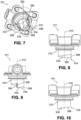
- Figures 7-10 show perspective, front, side, and rear views, respectively of the central portion 311 of the filter head 300.
- the central portion 311 may be molded, cast, or otherwise formed from a plastic material (e.g., polypropylene, high density polyethylene, polyvinyl chloride, nylon, etc.), a metal (e.g., aluminum, stainless steel, etc.), or any other suitable material.
- the skirt 312 includes a ramp 316 disposed at a first, lower end 318 of the skirt 312 and a plurality of seal disruptors, shown as ribs 320 disposed proximate to a second, upper end 322 of the skirt 312.
- the sealing interface 309 is disposed between the ramp 316 and a reference plane 324 passing through a lower edge 326 of each one of the plurality of ribs 320; the reference plane 324 extending parallel to the sealing interface 309 (e.g., parallel to the sealing member 230).
- the ramp 316 is formed in a helical shape that extends parallel to the central axis 310 of the filter head 300.
- the helical shape of the ramp 316 prevents a planar radial sealing element from fully engaging the skirt 312 proximate to the lower edge 326 of the skirt 312 (e.g., below the sealing interface 309).
- the anti-rotation member 244 (see also Figures 4-6 ) of the first endcap 216 is structured to engage a leading edge 328 of the ramp 316 (e.g., a stepwise transition in a height of the ramp 316) to rotationally position the interface member 220 with respect to the filter head 300 (e.g., to align the sealing member 230 with the sealing interface 309 as shown in Figure 2 ).
- a pitch 330 (e.g., a height) of the ramp 316, along the leading edge 328 of the ramp 316, is approximately equal to the height 250 of the anti-rotation member 244 (e.g., the tab 246 shown in Figure 6 ) in order to fully accommodate the anti-rotation member 244 during assembly.
- the pitch 330 of the ramp 316 is greater than the height 250 of the anti-rotation member 244.
- the pitch 330 of the ramp 316 is sized to prevent the anti-rotation member 244 (see also Figure 6 ) from engaging the lower edge 308 of the skirt 312 during installation of the shell housing 400 onto the filter head 300 (see Figure 1 ).
- the pitch 330 of the ramp 316 is sized to prevent the anti-rotation member 244 from contacting the ramp 316 at a circumferential position that is either before or after the leading edge 328 of the ramp 316.
- the pitch 330 of the ramp 316 is greater than a thread pitch of the male threaded portion 410 and the female threaded portion 302 (see also Figure 1 ).
- the pitch 330 of the ramp 316 is equal to an integer multiple of a thread pitch of the male threaded portion 410 and the female threaded portion 302 (e.g., four times the thread pitch, etc.).
- the skirt 312 includes a first inner surface 332 and a second inner surface 334 extending upwardly from the first inner surface 332 into the recessed area 314 of the skirt 312.
- the second inner surface 334 forms the sealing interface 309 at which the sealing member 230 engages the skirt 312.
- the first inner surface 332 at least partially forms an inner surface of the ramp 316.
- a transition 336 between the first inner surface 332 and the second inner surface 334 is oriented parallel to the sealing member 230.
- the transition 336 between the first inner surface 332 and the second inner surface 334 can be tilted at an angle with respect to the sealing member 230 (e.g., can be oriented in a slightly non-parallel angle, etc.) such that the seal engagement occurs locally/gradually vs. abruptly over the full seal perimeter, giving a "softer" more user-friendly installation feel, lacking an abrupt step-change in torque required.
- an inner diameter 337 of the second inner surface 334 is less than an inner diameter 338 of the first inner surface 332.
- the difference in (inner) diameter 337, 338 between the first inner surface 332 and the second inner surface 334 prevents damage to the sealing member 230 during assembly (e.g., prevents the sealing member 230 from rubbing against the first inner surface 332 as the sealing member 230 is pressed into the recessed area 314, past the first inner surface 332).
- the difference in (inner) diameter also prevents non-genuine filter cartridges without the proper structure from sealing against the ramped portion of the skirt 312.
- the plurality of ribs 320 are structured to prevent an improper filter cartridge from sealing along a portion of the recessed area 314 that is above the sealing interface 309.
- the ribs 320 will press against the seal to displace the seal and allow fluid to bypass between the clean and dirty sides of the filter cartridge.
- the ribs 320 could be replaced by indentations or grooves. The indentations or grooves would prevent proper sealing engagement between the non-matching, non-genuine filter cartridge and the filter head 300, despite being fully installed (e.g., axially) into the filter head 300.
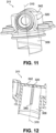
- FIGS 11-12 show perspective and cross-sectional views, respectively of the central portion 311 of the filter head 300.
- Each one of the plurality of ribs 320 includes a raised thin section of material extending upwardly (e.g., vertically upwardly as shown in Figures 11-12 ) from an upper edge 340 of the sealing interface 309, between the upper edge 340 and an upper wall 342 of the central portion 311.
- the ribs 320 are oriented parallel to the central axis 310 of the filter head 300. In other embodiments, the shape, number, and orientation of the ribs 320 may be different.
- the ribs 320 are integrally formed with the central portion 311 of the filter head 300 as a single unitary structure.
- the second endcap 218 of the filter cartridge 200 is detachably (e.g., removably) coupled to a lower wall 406 of the shell housing 400 via interlocking members disposed on the second endcap 218 and the lower wall 406.
- the interlocking members prevent axial movement of the filter cartridge 200 relative to the shell housing 400, while allowing the filter cartridge 200 to rotate under torsional loading relative to the shell housing 400 (e.g., relative to the central axis 404 of the shell housing 400).
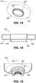
- Figures 13-14 show perspective and side views, respectively of the second endcap 218. Similar to the first endcap 216 of Figures 4-6 , the second endcap 218 of Figures 13-14 includes a base 254 that is structured to couple to the filter pack 202 (at a second end 214 of the filter pack 202 as shown in Figure 1 ).
- the second endcap 218 includes a male interlocking member 256 extending from a lower surface 258 of the second endcap 218 in substantially perpendicular orientation relative to the lower surface 258.
- the male interlocking member 256 includes a lip 260 (e.g., protrusion, ledge, etc.) extending circumferentially along an outer perimeter of the male interlocking member 256. As shown in Figure 3 , the male interlocking member 256 is structured to engage with a female interlocking member 418 disposed on the lower wall 406 of the shell housing 400.
- Figure 15 shows a perspective cross-sectional view of the shell housing 400 near the lower wall 406.
- the female interlocking member 418 includes a plurality of fingers 420 that extend upwardly (e.g., vertically upwardly as shown in Figure 15 ) from the lower wall 406 in substantially perpendicular orientation relative to the lower wall 406.
- Each one of the fingers 420 includes an inner latch 422 structured to engage with the lip 260 on the male interlocking member 256 (see also Figures 13-14 ).
- the inner latch 422 retains the lip 260, thereby securing the filter cartridge 200 in position (e.g., axially) relative to the shell housing 400.
- the fingers 420 are structured to deform (e.g., bend, flex) outwardly (e.g., radially outward relative to the central axis 404 of the shell housing 400) in response to an applied force from the male interlocking member 256.
- the female interlocking member 418 snaps (e.g., clicks, hooks, etc.) over the lip 260 on the male interlocking member 256 to secure the filter cartridge 200 in position.
- the frictional force between the male interlocking member 256 and the female interlocking member 418 prevents rotation of the filter cartridge 200 relative to the shell housing 400 in the absence of an applied torque between the filter cartridge 200 and the shell housing 400.
- the male interlocking member 256 and the female interlocking member 418 align the central axis 210 of the filter cartridge 200 with the central axis 404 of the shell housing 400 and position the filter cartridge 200 relative to the filter head 300 during assembly.
- Figures 16-20 show another example filter cartridge 1700 that is similar to the filter cartridge 200 of Figure 1 .
- the filter cartridge 1700 includes a first endcap 1716 coupled to a first end 1712 of the filter pack 1702 and a second endcap 1718 coupled to a second end 1714 of the filter pack 1702.
- the second endcap 1718 is a cup shaped plate that defines a substantially planar surface that covers the second end 1714.
- the first endcap 1716 includes an interface member 1720 that is configured to sealingly engage the filter cartridge 1700 to a filter head.
- the interface member 1720 includes a generally cylindrically-shaped protrusion 1722 extending from an upper surface 1724 of a base 1726 of the first endcap 1716.
- the protrusion 1722 extends upwardly (e.g., vertically upwards as shown in Figure 18 ) from the upper surface 1724 in substantially perpendicular orientation relative to the upper surface 1724.
- the protrusion 1722 defines a central opening, shown as through-hole 1728 (see Figure 20 ) that extends through the first endcap 1716. As shown in Figure 20 , the through-hole 1728 is axially aligned (in coaxial arrangement) with the central opening 1706 of the filter cartridge 1700.
- Figures 21-23 show the interface member 1720 engaged with a skirt 1812 of a filter head 1800.
- the interface member 1720 includes a sealing member 1730 that is sealingly engaged with the skirt 1812 along an angled sealing interface 1809.
- the skirt 1812 includes a plurality of ribs 1820 disposed proximate to an upper end 1822 of the skirt 1812.
- Each of the ribs 1820 extends downwardly from the upper end 1822 in substantially parallel orientation relative to a central axis 1810 of the skirt 1812.
- a height of each of the ribs 1820 is approximately uniform along the circumference of the skirt 1812.
- each of the ribs 1820 may be different (e.g., a lower end of each of the ribs 1820 may extend to the upper edge of the angled sealing interface 1809).
- the angled sealing interface 1809 separates a lower inner surface 1832 of the skirt 1812 from an upper inner surface 1834.
- the lower inner surface 1832 is spaced apart from the upper end 1822 by the upper inner surface 1834 and the angled sealing interface 1809.
- an inner diameter of the skirt decreases at a first transition 1844 between the lower inner surface 1832 and the angled sealing interface 1809, and also at a second transition 1846 between the angled sealing interface 1809 and the upper inner surface 1834.
- the change in diameter at the first transition 1844 is gradual to facilitate installation of the filter cartridge 1700 (e.g., interface member 1720) into the skirt 1812.
- the interface member 1720 also includes an anti-rotation member (e.g., tab) 1744, which may be the same as or similar to the anti-rotation member 244 described with reference to Figure 6 .
- the anti-rotation member 1744 is sized to engage with a slot 1848 that is disposed in a lower end 1824 of the skirt 1812.
- incorporating the slot 1848 into the skirt 1812 helps facilitate alignment between the filter cartridge 200 and the filter head 1800 during installation.
- the anti-rotation member 1744 engages with trailing edge 1828 of the slot 1848 during installation to fully align the interface member 1720 with the angled sealing interface 1809 (and to substantially prevent further rotation of the filter cartridge 1700).
- Figure 24 shows a central portion 611 of another example filter head.
- the central portion 611 includes a skirt 612, which may be the same or similar to the skirt 312 described with reference to Figures 7-12 .
- the skirt 612 of Figure 24 includes a plurality of seal disruptors, shown as outer ribs 644, disposed on an outer surface 646 of the skirt 612 and arranged in substantially parallel orientation relative to a central axis of the skirt 612.
- the outer ribs 644 extend along a length of the skirt 612 from an upper end of the skirt 612 to a lower end of the skirt 612.
- the outer ribs 644 prevent a non-matching, non-genuine filter element from sealing against the outer surface 646 (e.g., the outer ribs 644 prevent a radial sealing member of a non-genuine filter element from fully contacting the outer surface 646).
- the ribs 644 could be replaced by indentations or grooves to prevent non-matching, non-genuine filter element from sealing against the outer surface 646.
- FIGS 25-27 show a filter head 701 for another liquid filtration system 700.
- the filter head 701 includes a skirt 712 that is integrally formed with the filter head 701 as a single unitary structure.
- the sealing surfaces and ribs e.g., ramp 716, inner ribs 720, outer ribs 744, etc. are also integrally formed with the filter head 701 as opposed to including them as part of a separate cap or adapter.
- Figure 28 shows another example first endcap 816 of a filter cartridge (e.g., the filter cartridge 200 of Figure 1 ).
- the first endcap 816 is structured to support a sealing member 830 in a non-planar orientation.
- the first endcap 816 includes a groove 838.
- a first portion of the groove 838 is disposed along a first reference plane 862.
- the first reference plane 862 forms a first angle 864 with respect to a central axis 866 through the first endcap 816.
- a second portion of the groove 838 is disposed along a second reference plane 868.
- the second reference plane 868 forms a second angle 870 with respect to the central axis 866.
- the second angle 870 is greater than the first angle 864.
- the geometry of the groove 838 may be different and could include non-planar shapes such as parabolic hyperboloid seal shapes or simple curved shapes.
- the sealing member is at least partially tiled at an oblique angle with respect to a central axis of the filter cartridge.
- the filter cartridge may be structured to engage with the filter head along an axial sealing interface or a combination of an axial sealing interface and a radial sealing interface.
- a system 900 is shown to include a sealing member 930 that is sealingly engaged to a skirt 912 along a lower edge 913 of the skirt 912.
- the sealing member 930 forms an axial seal (e.g., an end-to-end sealing arrangement) with the skirt 912.
- a first endcap 916 of a filter cartridge for the system 900 includes an axial groove 915 structured (e.g., sized) to receive the sealing member 930 therein.
- the sealing member 930 is an irregular shape having non-uniform cross-sections normal to a central axis of the first endcap 916. As shown in Figure 30 , a height 917 of the sealing member 930, parallel to the central axis of the first endcap 916, varies with position along the axial groove 915.
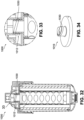
- Figures 32-34 show a system 1000 that includes a radial sealing member 1030 structured to sealingly engage a filter cartridge to a skirt 1012 along an inner surface of the skirt 1012 (e.g., in a radial sealing configuration).
- the sealing member 1030 has a substantially rectangular cross-section.
- the sealing member 1030 may be over molded onto a first endcap 1016 of the filter cartridge, or may be a simple cut-gasket installed in rectangular elliptical groove. In other embodiments, the geometry and/or arrangement of the sealing member 1030 may be different.
- Figures 35-37 show side views another example filter head 1101 where a sealing member is structured to seal against an outer surface 1146 of skirt 1112 rather than an inner surface.
- the filter head 1101 includes a plurality of indentations 1144 disposed on an outer surface 1146 of the skirt 1112 and arranged in substantially parallel orientation relative to a central axis of the skirt 1112.
- the indentations 1144 extend along a length of the skirt 1112 from an upper end of the skirt 1112 to a lower end of the skirt 1112.
- Figure 38 shows a top view at a cross-section through the skirt 1112.
- the indentations 1144 may be cut or otherwise formed into the outer surface 1146.
- the indentations 1144 prevent a non-matching, non-genuine filter element from sealing against the outer surface 1146 (e.g., the indentations 1144 prevent a radial sealing member of a non-genuine filter element from fully contacting the outer surface 1146).
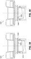
- FIG. 39 shows a side view of an example filter head 1201 that includes a plurality of bumps 1244 disposed on a lower surface 1203 of the filter head 1201 just above a skirt 1212 of the filter head 1201.
- Figure 40 shows a side view of an example filter head 1301 that includes a plurality of indentations 1344 on a lower surface 1303 of the filter head 1301.
- the first endcap of the fuel filter element may be modified to function as both an inlet and an outlet to the hollow portion of the shell housing.
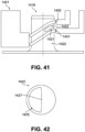
- Figures 41 and 42 show side and top views, respectively, of a first endcap 1416 of a filter element.
- the first endcap 1416 includes a cylindrically-shaped protrusion 1422.
- the protrusion 1422 includes an upper sealing member 1430 and a lower sealing member 1431.
- the lower sealing member 1431 is spaced apart from the upper sealing member 1430 vertically, along a central axis of the first endcap 1416.
- the protrusion 1422 additionally includes an opening 1421 extending through an outer wall of the protrusion 1422 along an approximately 180° portion of the outer wall.
- the protrusion 1422 additionally includes a partition 1427 defining two passageways through the protrusion 1422 (e.g., an inlet passageway that directs fuel into the hollow portion of the shell and an outlet passageway that directs fuel out from the hollow portion).
- a filter head 1401 is structured to engage with the protrusion 1422 to direct flow to at one of the passageways (e.g., passageway 1423) and to receive flow from the remaining passageway (e.g., passageway 1425).
- Figures 43 and 44 show side and top views, respectively, of another example first endcap 1516.
- the first endcap 1516 of Figures 43-44 includes a protrusion 1522 including an upper sealing member 1530 and a lower sealing member 1531 spaced vertically apart from the upper sealing member 1530.
- the protrusion 1522 defines three passageways, a first passageway 1523 extending through an upper surface of the protrusion 1522, a second passageway 1525 extending through a first opening 1521, and a third passageway 1527 extending through a second opening 1529 on an opposite side of the protrusion 1522 as the first opening 1521.
- the second passageway 1525 and the third passageway 1527 may be fluidly coupled.
- the number and/or geometry of the fluid passageways may be different.
- Figure 45 shows a system 1600 in which a transition 1636 between a first inner surface 1632 of a skirt 1612 (below the transition 1636) and a second inner surface 1634 of the skirt 1612 (above the transition 1636) is tilted at an angle 1605 with respect to a sealing member 1610 of the filter cartridge.
- tilting the transition 1636 relative to the sealing member 1610 ensures that engagement between the sealing member 1610 and a sealing interface of the skirt 1612 occurs gradually over a perimeter of the sealing interface (rather than abruptly all along the perimeter which would require a much larger force to overcome).
- the angle 1605 between the transition 1636 and the sealing member 1610 is approximately 10°.
- the oblique angle 1602 may be less than or equal to 10° relative to the sealing member 1610 or any other suitable angle to avoid an abrupt change in the compressive force acting between the skirt 1612 and the sealing member 1610 as the filter cartridge 1601 is inserted into the skirt 1612.
- FIG 46 is a flow diagram of a method 500 of installing a filter cartridge in a liquid filtration system.
- the liquid filtration system may be the same or similar to the system 100 described in detail with reference to Figure 1 .
- a filter head 300 is provided.
- Block 502 may include mounting the filter head 300 to an engine (e.g., an engine block) or to another location along a vehicle chassis (e.g., a frame rail, etc.).
- Block 502 may additionally include connecting fluid transfer lines to inlet and outlet ports on the central portion 311 of the filter head 300 in order to fluidly couple the filter head 300 to a fuel system.
- a shell housing 400 and a filter cartridge 200 are provided.
- the filter cartridge 200 is joined to the shell housing 400.
- Block 508 may additionally include aligning a central axis 210 of the filter cartridge 200 with a central axis 404 of the shell housing 400 and placing the filter cartridge 200 into a hollow portion 402 of the shell housing 400.
- Block 508 may further include coupling the filter cartridge 200 to the shell housing 400 (e.g., so that the filter cartridge 200 may rotate relative to the shell housing 400); for example, by connecting male interlocking member 256 and the female interlocking member 418 disposed on the filter cartridge 200 and the shell housing 400.
- the male interlocking member 256 and the female interlocking member 418 may be connected by pressing a second endcap 218 of the filter cartridge 200 (e.g., a male interlocking member 256 of the second endcap 218) toward a female interlocking member 418 on the shell housing 400 (at 510).
- Block 510 may additionally include expanding the female interlocking member 418 to snap, clip, or otherwise fasten the male interlocking member 256 to the female interlocking member 418.
- Block 512 may additionally include aligning the central axis 404 of the shell housing 400 with a central axis 310 of the filter head 300 such that the filter cartridge 200 and the shell housing 400 are in coaxial arrangement with respect to the filter head 300.
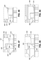
- Figures 47-50 show side views of an interface between the filter cartridge 200 and the filter head 300 during block 512 (e.g., the threading operation).
- the interface member 220 of the second endcap 218 is inserted into the recessed area 314 in the central portion 311 of the filter head 300.
- the shell housing 400 (not shown) is rotated relative to the filter head 300 (e.g., in a clockwise direction relative to the filter head 300) to draw the interface member 220 further into the recessed area 314.
- Block 512 may further include engaging an anti-rotation member 244 disposed on the filter cartridge 200 with the leading edge 328 of the ramp 316 on the filter head 300.
- the filter cartridge 200 rotates relative to the filter head 300 under the frictional force between the male interlocking member 256 and the female interlocking member 418 of the filter cartridge 200 and the shell housing 400.
- the filter cartridge 200 continues to rotate with the shell housing 400 until the anti-rotation member 244 is brought into contact with the leading edge 328 of the ramp 316 (see Figure 49 ).
- the engagement between the anti-rotation member 244 and the ramp 316 ensures that the sealing member 230 will remained aligned with the sealing interface 309 of the filter head 300 as the shell housing 400 is tightened onto the filter head 300.
- block 512 may additionally include pressing the interface member 220 of the filter cartridge 200 into the recessed area 314, from the first inner surface 332 of the recessed area 314 to the second inner surface 334 of the recessed area 314.
- a radial gap 600 is formed between the sealing member 230 and the first inner surface 332 of the recessed area 314.
- the sealing member 230 presses against the second inner surface 334, thereby sealing the filter cartridge 200 to the filter head 300.
- the method may include additional, fewer, and/or different operations.
- Coupled means the joining of two components directly or indirectly to one another. Such joining may be stationary (e.g., permanent) or moveable (e.g., removable or releasable). Such joining may be achieved with the two components or the two components and any additional intermediate components being integrally formed as a single unitary body with one another, with the two components, or with the two components and any additional intermediate components being attached to one another.
Landscapes
- Chemical & Material Sciences (AREA)
- Chemical Kinetics & Catalysis (AREA)
- Engineering & Computer Science (AREA)
- Mechanical Engineering (AREA)
- General Engineering & Computer Science (AREA)
- Lubrication Details And Ventilation Of Internal Combustion Engines (AREA)
- Filtration Of Liquid (AREA)
- Containers And Packaging Bodies Having A Special Means To Remove Contents (AREA)
Abstract
Description
- The present application claims the benefit of and priority to
Indian Provisional Patent Application No. 201941019992, entitled "Filtration Element with Gradient Seal Interface" and filed May 20, 2019 - The present application relates generally to liquid filtration systems for internal combustion engine systems.
- In various applications, it is generally desirable to minimize an amount of particulate contamination in liquids used to power and lubricate an internal combustion engine. The amount of particulate contamination can be reduced by passing the liquids through a filter element or cartridge, which captures solid particles entrained within the fluid. The structure of the cartridge and the materials used in the construction of the cartridge are carefully controlled by an original equipment manufacturer (OEM) in order to prevent damage to the engine and to ensure optimal engine performance.
- In some instances, a user may choose to replace the filter cartridge with a non-genuine (aftermarket) filter cartridge that is not produced by the OEM. The non-genuine filter cartridge may not adequately remove particulate contamination from the liquid which can, over a period of time, result in damage to the internal combustion engine.
- In one set of embodiments, a liquid filtration system includes a filter head, a shell housing, and a filter cartridge. The filter head includes a skirt having a ramp disposed at a first end of the skirt. The shell housing is coupled to the filter head. The filter cartridge is disposed within the shell housing. The filter cartridge includes a filter media pack and an endcap coupled to a first end of the filter media pack. The endcap includes an interface member extending from an upper surface of the endcap. The interface member includes a sealing member that is at least partially tilted at an oblique angle relative to a central axis of the endcap. The sealing member is sealingly engaged with the skirt.
- In another set of embodiments, a liquid filter cartridge includes a filter media pack and an endcap. The endcap is coupled to a first end of the filter media pack. The endcap includes an interface member that extends from an upper surface of the endcap. The interface member includes a sealing member that is at least partially tilted at an oblique angle with respect to a central axis of the filter media pack.
- In another set of embodiments, a method of installing a filter cartridge into a liquid filtration system includes providing a filter head, a shell housing, and a filter cartridge. The filter head includes a skirt having a ramp at a first end of the skirt. The filter cartridge includes a filter media pack and an endcap coupled to a first end of the filter media pack. The endcap includes an interface member extending from an upper surface of the endcap. The interface member includes a sealing member that is tilted at an oblique angle with respect to a central axis of the endcap. The method additionally includes joining the filter cartridge to the shell housing, and installing the shell housing onto the filter head to sealingly engage the sealing member to the skirt.
- The details of one or more implementations are set forth in the accompanying drawings and the description below. Other features, aspects, and advantages of the disclosure will become apparent from the description, the drawings, and the claims, in which:
-
Figure 1 is a side cross-sectional view of an example liquid filtration system; -
Figure 2 is a reproduction ofFigure 1 at a location where a filter cartridge of the liquid filtration system engages with a filter head of the liquid filtration system; -
Figure 3 is a reproduction ofFigure 1 at a location where a filter cartridge of the liquid filtration system engages with a shell housing of the liquid filtration system; -
Figure 4 is a perspective view of a first endcap of a filter cartridge used in the liquid filtration system ofFigure 1 ; -
Figures 5-6 are top and side views, respectively of the first endcap ofFigure 4 ; -
Figure 7 is a perspective view of a central portion of a filter head for the liquid filtration system ofFigure 1 ; -
Figure 8-10 are front, side, and rear views, respectively of the central portion ofFigure 7 ; -
Figure 11 is a perspective view of the central portion ofFigure 7 ; -
Figure 12 is a perspective cross-sectional view of the central portion ofFigure 7 ; -
Figure 13 is a perspective view of a second endcap of a filter cartridge used in the liquid filtration system ofFigure 1 ; -
Figure 14 is a side cross-sectional view of the second endcap ofFigure 13 ; -
Figure 15 is a perspective cross-sectional view of a lower portion of a shell housing used in the liquid filtration system ofFigure 1 ; -
Figure 16 is a top perspective view of another example filter cartridge; -
Figure 17 is a bottom perspective view of the filter cartridge ofFigure 16 ; -
Figure 18 is a side view of a first endcap portion of the filter cartridge ofFigure 16 ; -
Figure 19 is another side view of the first endcap portion of the filter cartridge ofFigure 16 ; -
Figure 20 is a top view of the filter cartridge ofFigure 16 ; -
Figure 21 is a side cross-sectional view of a first endcap portion of the filter cartridge ofFigure 16 engaged with a filter head; -
Figure 22 is another cross-sectional view of the first endcap portion of the filter cartridge ofFigure 16 engaged with a filter head; -
Figure 23 is a perspective view of a skirt portion of a filter head; -
Figure 24 is a perspective view of a central portion of a filter head for another example liquid filtration system; -
Figure 25 is a side cross-sectional view of another liquid filtration system; -
Figure 26 is a side cross-sectional view of a filter head for the liquid filtration system ofFigure 25 ; -
Figure 27 is a lower perspective view of the filter head ofFigure 26 ; -
Figure 28 is a side view of a first endcap of a filter element for yet another example liquid filtration system; -
Figure 29 is a side cross-sectional view of still another liquid filtration system; -
Figure 30 is a reproduction ofFigure 29 near a sealing interface; -
Figure 31 is a top perspective view of a first endcap of a filter element for the liquid filtration system ofFigure 29 ; -
Figure 32 is a side cross-sectional view of another liquid filtration system; -
Figure 33 is a reproduction ofFigure 32 near a sealing interface; -
Figure 34 is a perspective view of a first endcap of a filter element for the liquid filtration system ofFigure 32 ; -
Figures 35-37 are side views of a central portion of a filter head for another liquid filtration system; -
Figure 38 is a top cross-sectional view through a skirt of the central portion ofFigures 35-37 ; -
Figure 39 is a central portion of a filter head for another liquid filtration system; -
Figure 40 is a central portion of a filter head for yet another liquid filtration system; -
Figure 41 is a side view of a first endcap of a filter element for another liquid filtration system; -
Figure 42 is a top view of the first endcap ofFigure 41 ; -
Figure 43 is a side view of a first endcap of a filter element for another liquid filtration system; -
Figure 44 is a top view of the first endcap ofFigure 43 ; -
Figure 45 is a side cross-sectional view of another example liquid filtration system; -
Figure 46 is a flow diagram of a method of installing a filter cartridge into a liquid filtration system; -
Figures 47-50 are side views of a filter cartridge at different rotational positions with respect to a filter head; -
Figure 51 is a side cross-sectional view of a partially installed filter cartridge; -
Figure 52 is a reproduction ofFigure 51 near a sealing member of the filter cartridge; -
Figure 53 is a side cross-sectional view of a fully installed filter cartridge; and -
Figure 54 is a reproduction ofFigure 53 near a sealing member of the filter cartridge. - It will be recognized that some or all of the figures are schematic representations for purposes of illustration. The figures are provided for the purpose of illustrating one or more implementations with the explicit understanding that they will not be used to limit the scope or the meaning of the claims.
- Following below are more detailed descriptions of various concepts related to, and implementations of, methods, apparatuses, and systems for sealing a filter cartridge to a liquid filtration system. The various concepts introduced above and discussed in greater detail below may be implemented in any of numerous ways, as the described concepts are not limited to any particular manner of implementation. Examples of specific implementations and applications are provided primarily for illustrative purposes.
- Internal combustion engine systems require a clean source of fuel to power the engine. Unfiltered fuel may include dirt, metal particles, and other solid contaminants that can damage fuel injectors and other engine components. In order to protect the injectors, many internal combustion engine systems include fuel filtration systems, which filter the fuel to remove any solid materials before passing the fuel to the injectors. The filtration system may include a shell housing, a filter head, and a filter cartridge. In operation, the filtration system directs the fuel through the filter cartridge, which includes a media that captures any solid particulate entrained in the fuel. The performance of the filtration system depends, among other factors, on the structure of the filter cartridge and the materials used to construct the filter cartridge (e.g., the materials used to produce a filter media for the filter cartridge, the specifications of the filter media pack such as the flow area of the filter media pack, the pleat depth of the filter media pack, and other factors).
- Over time, accumulated particulate on the filter cartridge (e.g., carbon, dust, metal particles, etc.) can increase the pressure drop across the filter cartridge (and, correspondingly, a pressure drop across a fuel delivery system for the engine). In order to reduce the pressure drop, the filter cartridge can be removed from the filtration system and replaced with a clean filter cartridge. In some instances, a user may elect to replace the filter cartridge with a non-genuine (aftermarket) filter cartridge; for example, in order to reduce maintenance costs. However, the filtration performance of the aftermarket filter cartridges can be much lower than an OEM filter cartridge. Over time, operating with the aftermarket filter cartridge may result in damage to the injectors and/or other parts of the engine, thereby leading to a reduction in engine performance.
Implementations herein relate to methods and systems including a unique sealing interface between a filter cartridge and a filter head. The sealing interface includes a sealing member (e.g., O-ring, etc.) extending in a plane that is tilted at an oblique angle relative to a central axis (e.g., longitudinal axis) of the filter cartridge. The sealing member engages a skirt on the filter head at a fixed orientation relative to the skirt to form a seal between sealing member and the skirt. In order to ensure that the sealing member is properly aligned within the skirt during installation, the sealing interface additionally includes an anti-rotation member, which engages (e.g., contacts) a leading edge of the ramped skirt to reorient the filter cartridge into alignment relative to a sealing interface on the filter head. Implementations herein also relate to a filter head that includes a plurality of vertical ribs and/or a plurality of indentations (e.g., grooves) that restrict the use of non-matching, non-genuine filter cartridges including planar radial seals. -
Figure 1 is a perspective view of a first example liquid filtration system, shown assystem 100. Thesystem 100 may be used to filter a fluid provided to an internal combustion engine. The fluid may be a fuel, an engine oil, a hydraulic oil, or another lubricant. In the example embodiment ofFigure 1 , thesystem 100 is a fuel filtration system for a diesel engine that uses diesel fuel to drive the combustion process. Thesystem 100 is configured to be mounted on the diesel engine. In other embodiments, thesystem 100 may be configured to be mounted remotely from the engine (e.g., on a vehicle chassis, etc.). - As shown in
Figure 1 , thesystem 100 includes afilter cartridge 200, afilter head 300, and ashell housing 400. Thefilter cartridge 200 is disposed within ahollow portion 402 of theshell housing 400 and is coaxial with respect to acentral axis 404 of theshell housing 400. Thefilter cartridge 200 is a cylindrically-shaped cartridge having a cylindrically-shapedfilter pack 202. Thefilter pack 202 includes afilter media 204 configured to filter particulate matter from a fluid flowing therethrough so as to produce filtered fluid (e.g., clean fluid). Thefilter media 204 may include a porous material having a predetermined pore size. Thefilter media 204 may include a paper-based filter media, a fiber-based filter media, a foam-based filter media, or the like. Thefilter media 204 may be pleated or formed into another desired shape to increase a flow area through thefilter pack 202, or to otherwise alter the particle removal efficiency of thefilter cartridge 200. Thefilter cartridge 200 may be arranged as an outside-in flow filter cartridge having an outer dirty side and an inner clean side. In an alternative arrangement, thefilter cartridge 200 is an inside-out filter cartridge having an inner dirty side and an outer clean side. Fluid to be filtered passes from the dirty side of thefilter cartridge 200 to the clean side of thefilter cartridge 200. - The
filter pack 202 defines acentral opening 206 extending along a central axis 210 (e.g., a longitudinal axis, up and down as shown inFigure 1 ) of thefilter cartridge 200. Thecentral opening 206 is sized to receive a center support tube 208 therein. The support tube 208 extends longitudinally along at least a portion of thecentral opening 206 from a first,upper end 212 of thefilter cartridge 200 to a second,bottom end 214 of thefilter cartridge 200. As shown inFigure 1 , the support tube 208 is formed in the shape of a hollow cylinder. An outer wall of the support tube 208 is perforated in order to allow fluid to pass through the support tube 208. - The
shell housing 400 defines ahollow portion 402 having an inner cross-sectional diameter within which thefilter cartridge 200 is positioned. The shell housing 400 (e.g., a filter housing, container, or reservoir) includes alower wall 406 and asidewall 408 extending upwardly from thelower wall 406 in substantially perpendicular orientation relative to thelower wall 406. Theshell housing 400 may be formed form a strong and rigid material. For example, theshell housing 400 may be formed from a plastic material (e.g., polypropylene, high density polyethylene, polyvinyl chloride, nylon, etc.), a metal (e.g., aluminum, stainless steel, etc.), or another suitable material. The cross-sectional shape of theshell housing 400 may be the same or similar to the cross-sectional shape of thefilter cartridge 200. As shown inFigure 1 , theshell housing 400 is formed in the shape of a cylinder such that theshell housing 400 has a generally circular cross-section normal to thecentral axis 404 of theshell housing 400. In other embodiments, theshell housing 400 may have any other suitable cross-sectional shape; for example, circular, oval, rectangular, or another suitable shape. - As shown in
Figure 1 , theshell housing 400 is threadably coupled to thefilter head 300. Theshell housing 400 includes a male threadedportion 410 disposed on an outer surface 414 of theshell housing 400 and extending downwardly (e.g., parallel to thecentral axis 404 of the shell housing 400) from a first, upper end 416 of theshell housing 400. The male threadedportion 410 is engaged with a female threadedportion 302 of thefilter head 300. As shown inFigure 1 , the female threadedportion 302 is disposed on aninner surface 304 of anouter flange 306 of thefilter head 300 such that, in an installed position (as shown inFigure 1 ), theouter flange 306 at least partially surrounds theshell housing 400. Theshell housing 400 and/or thefilter head 300 may include one or more sealing mechanisms to prevent fluid from leaking into an environment surrounding thesystem 100. As shown inFigure 1 , theshell housing 400 includes a radial sealing member 412 (e.g., an O-ring, etc.) that presses against theinner surface 304 of theouter flange 306 proximate to alower edge 308 of theouter flange 306. - The
filter cartridge 200 is structured to detachably (e.g., removably) couple to theshell housing 400 and thefilter head 300. Thefilter cartridge 200 includes afirst endcap 216 coupled to thefirst end 212 of thefilter cartridge 200 and asecond endcap 218 coupled to thesecond end 214 of thefilter cartridge 200. Thefirst endcap 216 and thesecond endcap 218 may be coupled to thefilter pack 202 using glue or another suitable bonding agent (e.g., adhesive product) in order to seal thefirst end 212 and thesecond end 214 of thefilter pack 202 and to prevent dirty fluid from bypassing thefilter media 204 through thefirst end 212 and thesecond end 214.Figures 2 and 3 show side cross-sectional views of thesystem 100 at 1) an interface between thefirst endcap 216 and the filter head 300 (Figure 2), and 2 ) an interface between thesecond endcap 218 and the shell housing 400 (Figure 3 ). As shown inFigure 2 , thefirst endcap 216 includes aninterface member 220 structured to engage with thefilter head 300 in order to fluidly couple thefilter cartridge 200 to thefilter head 300. -
Figures 4-6 show perspective, side, and top views, respectively, of thefirst endcap 216 of thefilter cartridge 200. Theinterface member 220 includes a generally cylindrically-shapedprotrusion 222 extending from anupper surface 224 of abase 226 of thefirst endcap 216. Theprotrusion 222 extends upwardly (e.g., vertically upwards as shown inFigure 6 ) from theupper surface 224 in substantially perpendicular orientation relative to theupper surface 224. Theprotrusion 222 defines a central opening, shown as through-hole 228 that extends through thefirst endcap 216. As shown inFigure 2 , the through-hole 228 is axially aligned (in coaxial arrangement) with thecentral opening 206 of thefilter cartridge 200 and acentral axis 310 of thefilter head 300. - The
interface member 220 engages thefilter head 300 along anangled sealing interface 309. Among other benefits, the orientation of the sealinginterface 309 prevents the use of non-genuine filter cartridges that rely on planar radial sealing elements (e.g., sealing elements that extend normal to the central axis 210 of the filter cartridge 200). As shown inFigure 2 , theinterface member 220 additionally includes a sealing member 230 (e.g., an O-ring, etc.) that is sealingly engaged with thefilter head 300 in order to prevent fluid bypass between theinterface member 220 and thefilter head 300. The sealingmember 230 is tilted at an oblique angle 232 (e.g., an angle other than 90°) with respect to the central axis 210 of thefilter cartridge 200 such that a cross-section through the sealingmember 230 forms an ellipse. For example, theoblique angle 232 may be approximately 75° or within a range between approximately 50°-85°. In other embodiments, theoblique angle 232 may be within different ranges. - As shown in
Figure 6 , thefirst endcap 216 of thefilter cartridge 200 includes anupper extension piece 234 and alower extension piece 236 that each extend radially outward from the cylindrically-shapedprotrusion 222. Thelower extension piece 236 that is parallel (or substantially parallel) to theupper extension piece 234. Thelower extension piece 236 is spaced apart from theupper extension piece 234. Together, theupper extension piece 234 and thelower extension piece 236 form agroove 238 structured (e.g., sized) to receive the sealingmember 230 therein. Thegroove 238 is sized to prevent movement of the sealingmember 230 relative tofirst endcap 216 and theprotrusion 222. As shown inFigure 6 , anupper edge 240 of theupper extension piece 234 is approximately coplanar (e.g., flush) with an upper surface 242 (e.g., upper end, upper edge, etc.) of theprotrusion 222. - As shown in
Figure 2 , rotational alignment between theinterface member 220 and thefilter head 300 is required in order to ensure a liquid-tight seal is formed between theinterface member 220 and thefilter head 300. As shown inFigures 4-6 , thefirst endcap 216 includes ananti-rotation member 244 structured to engage with thefilter head 300 in order to position the sealing member 230 (see alsoFigure 2 ) along the sealinginterface 309. Theanti-rotation member 244 includes a generally rectangular-shapedtab 246 disposed along anouter surface 248 of theprotrusion 222. Thetab 246 engages the interface member 220 (e.g., the protrusion 222), and extends radially away from theinterface member 220 such that there is no gap between theanti-rotation member 244 and theinterface member 220. In some embodiments, thetab 246 is a separate component from theinterface member 220 and contacts (e.g., is disposed on) theinterface member 220. In the embodiment shown inFigures 4-6 , thetab 246 is integrally formed with at least one of theinterface member 220 or thefirst endcap 216 as a single unitary body. Thetab 246 also extends upwardly from theupper surface 242 in substantially perpendicular orientation relative to theupper surface 242. As shown inFigure 6 , aheight 250 of thetab 246 along theouter surface 248 of the protrusion 222 (e.g., parallel to a central axis through the first endcap 216) is approximately the same as avertical distance 252 between theupper surface 242 and a lowermost end of thelower extension piece 236. - As shown in
Figures 4-5 , thefirst endcap 216 includes a pair ofcoupling members 223 that are structured to mechanically connect (e.g., couple, etc.) the first endcap 216 (and the liquid filter cartridge 200) to theshell housing 400. Thecoupling members 223 are configured to engage with the housing along an upper edge of theshell housing 400. In some embodiments, thecoupling members 223 form a portion of a clip, latch, clasp, or another quick connect interface. As shown inFigures 4-5 , eachcoupling member 223 is an extension piece that extends radially outward from an outer perimeter of thefirst endcap 216. In other embodiments, the size, shape, and arrangement of thecoupling members 223 may be different. - As shown in
Figure 2 , the sealingmember 230 is structured to press radially outwardly against acentral portion 311 of thefilter head 300 to form a seal between theinterface member 220 and thefilter head 300. Thecentral portion 311 includes askirt 312 that extends downwardly (e.g., vertically downward as shown inFigure 2 ) in substantially parallel orientation relative to thecentral axis 310 of thefilter head 300. Theskirt 312 defines a cylindrically-shaped recessedarea 314 that is sized to receive theinterface member 220 therein (such that theinterface member 220 is at least partially surrounded by the skirt 312). -
Figures 7-10 show perspective, front, side, and rear views, respectively of thecentral portion 311 of thefilter head 300. Thecentral portion 311 may be molded, cast, or otherwise formed from a plastic material (e.g., polypropylene, high density polyethylene, polyvinyl chloride, nylon, etc.), a metal (e.g., aluminum, stainless steel, etc.), or any other suitable material. Theskirt 312 includes aramp 316 disposed at a first,lower end 318 of theskirt 312 and a plurality of seal disruptors, shown asribs 320 disposed proximate to a second,upper end 322 of theskirt 312. As shown inFigure 2 , the sealinginterface 309 is disposed between theramp 316 and areference plane 324 passing through alower edge 326 of each one of the plurality ofribs 320; thereference plane 324 extending parallel to the sealing interface 309 (e.g., parallel to the sealing member 230). As shown inFigures 7-10 , theramp 316 is formed in a helical shape that extends parallel to thecentral axis 310 of thefilter head 300. Among other benefits, the helical shape of theramp 316 prevents a planar radial sealing element from fully engaging theskirt 312 proximate to thelower edge 326 of the skirt 312 (e.g., below the sealing interface 309). - As will be further described, the anti-rotation member 244 (see also
Figures 4-6 ) of thefirst endcap 216 is structured to engage aleading edge 328 of the ramp 316 (e.g., a stepwise transition in a height of the ramp 316) to rotationally position theinterface member 220 with respect to the filter head 300 (e.g., to align the sealingmember 230 with the sealinginterface 309 as shown inFigure 2 ). As shown inFigure 9 , a pitch 330 (e.g., a height) of theramp 316, along theleading edge 328 of theramp 316, is approximately equal to theheight 250 of the anti-rotation member 244 (e.g., thetab 246 shown inFigure 6 ) in order to fully accommodate theanti-rotation member 244 during assembly. In other embodiments, thepitch 330 of theramp 316 is greater than theheight 250 of theanti-rotation member 244. - Referring now to
Figure 9 , thepitch 330 of theramp 316 is sized to prevent the anti-rotation member 244 (see alsoFigure 6 ) from engaging thelower edge 308 of theskirt 312 during installation of theshell housing 400 onto the filter head 300 (seeFigure 1 ). In other words, thepitch 330 of theramp 316 is sized to prevent theanti-rotation member 244 from contacting theramp 316 at a circumferential position that is either before or after theleading edge 328 of theramp 316. In various example embodiments, thepitch 330 of theramp 316 is greater than a thread pitch of the male threadedportion 410 and the female threaded portion 302 (see alsoFigure 1 ). In theexample system 100 ofFigure 1 , thepitch 330 of theramp 316 is equal to an integer multiple of a thread pitch of the male threadedportion 410 and the female threaded portion 302 (e.g., four times the thread pitch, etc.). - As shown in
Figure 2 , theskirt 312 includes a firstinner surface 332 and a secondinner surface 334 extending upwardly from the firstinner surface 332 into the recessedarea 314 of theskirt 312. The secondinner surface 334 forms the sealinginterface 309 at which the sealingmember 230 engages theskirt 312. The firstinner surface 332 at least partially forms an inner surface of theramp 316. Atransition 336 between the firstinner surface 332 and the secondinner surface 334 is oriented parallel to the sealingmember 230. Alternatively, thetransition 336 between the firstinner surface 332 and the secondinner surface 334 can be tilted at an angle with respect to the sealing member 230 (e.g., can be oriented in a slightly non-parallel angle, etc.) such that the seal engagement occurs locally/gradually vs. abruptly over the full seal perimeter, giving a "softer" more user-friendly installation feel, lacking an abrupt step-change in torque required. In theexample system 100 ofFigure 2 , aninner diameter 337 of the secondinner surface 334 is less than aninner diameter 338 of the firstinner surface 332. Among other benefits, the difference in (inner)diameter inner surface 332 and the secondinner surface 334 prevents damage to the sealingmember 230 during assembly (e.g., prevents the sealingmember 230 from rubbing against the firstinner surface 332 as the sealingmember 230 is pressed into the recessedarea 314, past the first inner surface 332). The difference in (inner) diameter also prevents non-genuine filter cartridges without the proper structure from sealing against the ramped portion of theskirt 312. - The plurality of ribs 320 (or, alternatively, grooves) are structured to prevent an improper filter cartridge from sealing along a portion of the recessed
area 314 that is above the sealinginterface 309. In the event that a non-matching, non-genuine filter cartridge without the proper arrangement is installed into thefilter head 300, theribs 320 will press against the seal to displace the seal and allow fluid to bypass between the clean and dirty sides of the filter cartridge. In an alternative example, theribs 320 could be replaced by indentations or grooves. The indentations or grooves would prevent proper sealing engagement between the non-matching, non-genuine filter cartridge and thefilter head 300, despite being fully installed (e.g., axially) into thefilter head 300.Figures 11-12 show perspective and cross-sectional views, respectively of thecentral portion 311 of thefilter head 300. Each one of the plurality ofribs 320 includes a raised thin section of material extending upwardly (e.g., vertically upwardly as shown inFigures 11-12 ) from anupper edge 340 of the sealinginterface 309, between theupper edge 340 and anupper wall 342 of thecentral portion 311. Theribs 320 are oriented parallel to thecentral axis 310 of thefilter head 300. In other embodiments, the shape, number, and orientation of theribs 320 may be different. In various example embodiments, theribs 320 are integrally formed with thecentral portion 311 of thefilter head 300 as a single unitary structure. - Referring now to
Figure 3 , thesecond endcap 218 of thefilter cartridge 200 is detachably (e.g., removably) coupled to alower wall 406 of theshell housing 400 via interlocking members disposed on thesecond endcap 218 and thelower wall 406. The interlocking members prevent axial movement of thefilter cartridge 200 relative to theshell housing 400, while allowing thefilter cartridge 200 to rotate under torsional loading relative to the shell housing 400 (e.g., relative to thecentral axis 404 of the shell housing 400). -
Figures 13-14 show perspective and side views, respectively of thesecond endcap 218. Similar to thefirst endcap 216 ofFigures 4-6 , thesecond endcap 218 ofFigures 13-14 includes a base 254 that is structured to couple to the filter pack 202 (at asecond end 214 of thefilter pack 202 as shown inFigure 1 ). Thesecond endcap 218 includes a male interlockingmember 256 extending from alower surface 258 of thesecond endcap 218 in substantially perpendicular orientation relative to thelower surface 258. Themale interlocking member 256 includes a lip 260 (e.g., protrusion, ledge, etc.) extending circumferentially along an outer perimeter of the male interlockingmember 256. As shown inFigure 3 , the male interlockingmember 256 is structured to engage with afemale interlocking member 418 disposed on thelower wall 406 of theshell housing 400. -
Figure 15 shows a perspective cross-sectional view of theshell housing 400 near thelower wall 406. Thefemale interlocking member 418 includes a plurality offingers 420 that extend upwardly (e.g., vertically upwardly as shown inFigure 15 ) from thelower wall 406 in substantially perpendicular orientation relative to thelower wall 406. Each one of thefingers 420 includes aninner latch 422 structured to engage with thelip 260 on the male interlocking member 256 (see alsoFigures 13-14 ). Theinner latch 422 retains thelip 260, thereby securing thefilter cartridge 200 in position (e.g., axially) relative to theshell housing 400. In the example embodiment ofFigure 15 , thefingers 420 are structured to deform (e.g., bend, flex) outwardly (e.g., radially outward relative to thecentral axis 404 of the shell housing 400) in response to an applied force from the male interlockingmember 256. In this way, thefemale interlocking member 418 snaps (e.g., clicks, hooks, etc.) over thelip 260 on the male interlockingmember 256 to secure thefilter cartridge 200 in position. The frictional force between the male interlockingmember 256 and thefemale interlocking member 418 prevents rotation of thefilter cartridge 200 relative to theshell housing 400 in the absence of an applied torque between thefilter cartridge 200 and theshell housing 400. Among other benefits, as shown inFigure 2 , the male interlockingmember 256 and thefemale interlocking member 418 align the central axis 210 of thefilter cartridge 200 with thecentral axis 404 of theshell housing 400 and position thefilter cartridge 200 relative to thefilter head 300 during assembly. - The combination of features shown in the
example system 100 ofFigures 1-15 should not be considered limiting, and a variety of alternatives are possible without departing from the inventive concepts disclosed herein. For example,Figures 16-20 show anotherexample filter cartridge 1700 that is similar to thefilter cartridge 200 ofFigure 1 . Thefilter cartridge 1700 includes afirst endcap 1716 coupled to afirst end 1712 of thefilter pack 1702 and asecond endcap 1718 coupled to asecond end 1714 of thefilter pack 1702. Thesecond endcap 1718 is a cup shaped plate that defines a substantially planar surface that covers thesecond end 1714. - As shown in
Figures 18-20 , thefirst endcap 1716 includes aninterface member 1720 that is configured to sealingly engage thefilter cartridge 1700 to a filter head. Theinterface member 1720 includes a generally cylindrically-shapedprotrusion 1722 extending from anupper surface 1724 of abase 1726 of thefirst endcap 1716. Theprotrusion 1722 extends upwardly (e.g., vertically upwards as shown inFigure 18 ) from theupper surface 1724 in substantially perpendicular orientation relative to theupper surface 1724. Theprotrusion 1722 defines a central opening, shown as through-hole 1728 (seeFigure 20 ) that extends through thefirst endcap 1716. As shown inFigure 20 , the through-hole 1728 is axially aligned (in coaxial arrangement) with thecentral opening 1706 of thefilter cartridge 1700. -
Figures 21-23 show theinterface member 1720 engaged with askirt 1812 of afilter head 1800. In particular, theinterface member 1720 includes a sealingmember 1730 that is sealingly engaged with theskirt 1812 along anangled sealing interface 1809. As shown inFigures 21 and 23 , theskirt 1812 includes a plurality ofribs 1820 disposed proximate to anupper end 1822 of theskirt 1812. Each of theribs 1820 extends downwardly from theupper end 1822 in substantially parallel orientation relative to acentral axis 1810 of theskirt 1812. A height of each of theribs 1820 is approximately uniform along the circumference of theskirt 1812. In other embodiments, the height of each of theribs 1820 may be different (e.g., a lower end of each of theribs 1820 may extend to the upper edge of the angled sealing interface 1809). As shown inFigure 21 , theangled sealing interface 1809 separates a lowerinner surface 1832 of theskirt 1812 from an upperinner surface 1834. The lowerinner surface 1832 is spaced apart from theupper end 1822 by the upperinner surface 1834 and theangled sealing interface 1809. As shown inFigure 21 , an inner diameter of the skirt decreases at afirst transition 1844 between the lowerinner surface 1832 and theangled sealing interface 1809, and also at asecond transition 1846 between theangled sealing interface 1809 and the upperinner surface 1834. As shown inFigure 21 , the change in diameter at thefirst transition 1844 is gradual to facilitate installation of the filter cartridge 1700 (e.g., interface member 1720) into theskirt 1812. - As shown in
Figure 22 , theinterface member 1720 also includes an anti-rotation member (e.g., tab) 1744, which may be the same as or similar to theanti-rotation member 244 described with reference toFigure 6 . As shown inFigures 22-23 , theanti-rotation member 1744 is sized to engage with aslot 1848 that is disposed in alower end 1824 of theskirt 1812. Among other benefits, incorporating theslot 1848 into theskirt 1812 helps facilitate alignment between thefilter cartridge 200 and thefilter head 1800 during installation. As shown inFigure 22 , theanti-rotation member 1744 engages with trailingedge 1828 of theslot 1848 during installation to fully align theinterface member 1720 with the angled sealing interface 1809 (and to substantially prevent further rotation of the filter cartridge 1700). -
Figure 24 shows acentral portion 611 of another example filter head. Thecentral portion 611 includes askirt 612, which may be the same or similar to theskirt 312 described with reference toFigures 7-12 . Additionally, theskirt 612 ofFigure 24 includes a plurality of seal disruptors, shown asouter ribs 644, disposed on anouter surface 646 of theskirt 612 and arranged in substantially parallel orientation relative to a central axis of theskirt 612. Theouter ribs 644 extend along a length of theskirt 612 from an upper end of theskirt 612 to a lower end of theskirt 612. Among other benefits, theouter ribs 644 prevent a non-matching, non-genuine filter element from sealing against the outer surface 646 (e.g., theouter ribs 644 prevent a radial sealing member of a non-genuine filter element from fully contacting the outer surface 646). Alternatively, theribs 644 could be replaced by indentations or grooves to prevent non-matching, non-genuine filter element from sealing against theouter surface 646. -
Figures 25-27 show afilter head 701 for anotherliquid filtration system 700. Thefilter head 701 includes askirt 712 that is integrally formed with thefilter head 701 as a single unitary structure. The sealing surfaces and ribs (e.g.,ramp 716,inner ribs 720,outer ribs 744, etc.) are also integrally formed with thefilter head 701 as opposed to including them as part of a separate cap or adapter. -
Figure 28 shows another examplefirst endcap 816 of a filter cartridge (e.g., thefilter cartridge 200 ofFigure 1 ). Thefirst endcap 816 is structured to support a sealingmember 830 in a non-planar orientation. Thefirst endcap 816 includes agroove 838. A first portion of thegroove 838 is disposed along afirst reference plane 862. Thefirst reference plane 862 forms afirst angle 864 with respect to acentral axis 866 through thefirst endcap 816. A second portion of thegroove 838 is disposed along asecond reference plane 868. Thesecond reference plane 868 forms asecond angle 870 with respect to thecentral axis 866. In the embodiment ofFigure 28 , thesecond angle 870 is greater than thefirst angle 864. In other embodiments, the geometry of thegroove 838 may be different and could include non-planar shapes such as parabolic hyperboloid seal shapes or simple curved shapes. In embodiments where thegroove 838 is non-planar (e.g., tilted at multiple angles, curved, etc.), the sealing member is at least partially tiled at an oblique angle with respect to a central axis of the filter cartridge. - In some embodiments, the filter cartridge may be structured to engage with the filter head along an axial sealing interface or a combination of an axial sealing interface and a radial sealing interface. Referring to
Figures 29-31 , asystem 900 is shown to include a sealingmember 930 that is sealingly engaged to askirt 912 along alower edge 913 of theskirt 912. The sealingmember 930 forms an axial seal (e.g., an end-to-end sealing arrangement) with theskirt 912. As shown inFigure 31 , afirst endcap 916 of a filter cartridge for thesystem 900 includes anaxial groove 915 structured (e.g., sized) to receive the sealingmember 930 therein. The sealingmember 930 is an irregular shape having non-uniform cross-sections normal to a central axis of thefirst endcap 916. As shown inFigure 30 , aheight 917 of the sealingmember 930, parallel to the central axis of thefirst endcap 916, varies with position along theaxial groove 915. - Other types of sealing members are also contemplated. For example,
Figures 32-34 show asystem 1000 that includes aradial sealing member 1030 structured to sealingly engage a filter cartridge to askirt 1012 along an inner surface of the skirt 1012 (e.g., in a radial sealing configuration). As shown inFigures 33-34 , the sealingmember 1030 has a substantially rectangular cross-section. The sealingmember 1030 may be over molded onto afirst endcap 1016 of the filter cartridge, or may be a simple cut-gasket installed in rectangular elliptical groove. In other embodiments, the geometry and/or arrangement of the sealingmember 1030 may be different. -
Figures 35-37 show side views another example filter head 1101 where a sealing member is structured to seal against anouter surface 1146 ofskirt 1112 rather than an inner surface. As shown, the filter head 1101 includes a plurality ofindentations 1144 disposed on anouter surface 1146 of theskirt 1112 and arranged in substantially parallel orientation relative to a central axis of theskirt 1112. Theindentations 1144 extend along a length of theskirt 1112 from an upper end of theskirt 1112 to a lower end of theskirt 1112.Figure 38 shows a top view at a cross-section through theskirt 1112. Theindentations 1144 may be cut or otherwise formed into theouter surface 1146. Among other benefits, theindentations 1144 prevent a non-matching, non-genuine filter element from sealing against the outer surface 1146 (e.g., theindentations 1144 prevent a radial sealing member of a non-genuine filter element from fully contacting the outer surface 1146). - Similar features may be formed into the filter head to prevent a non-matching, non-genuine filter element from forming an axial seal with the filter head (e.g., to prevent an axial sealing member from fully contacting a surface of the filter head).
Figures 39 shows a side view of anexample filter head 1201 that includes a plurality ofbumps 1244 disposed on alower surface 1203 of thefilter head 1201 just above askirt 1212 of thefilter head 1201.Figure 40 shows a side view of anexample filter head 1301 that includes a plurality ofindentations 1344 on alower surface 1303 of thefilter head 1301. - In some embodiments, the first endcap of the fuel filter element may be modified to function as both an inlet and an outlet to the hollow portion of the shell housing.
Figures 41 and 42 show side and top views, respectively, of afirst endcap 1416 of a filter element. Thefirst endcap 1416 includes a cylindrically-shapedprotrusion 1422. Theprotrusion 1422 includes anupper sealing member 1430 and alower sealing member 1431. Thelower sealing member 1431 is spaced apart from theupper sealing member 1430 vertically, along a central axis of thefirst endcap 1416. Theprotrusion 1422 additionally includes anopening 1421 extending through an outer wall of theprotrusion 1422 along an approximately 180° portion of the outer wall. As shown inFigure 42 , theprotrusion 1422 additionally includes apartition 1427 defining two passageways through the protrusion 1422 (e.g., an inlet passageway that directs fuel into the hollow portion of the shell and an outlet passageway that directs fuel out from the hollow portion). As shown inFigure 41 , afilter head 1401 is structured to engage with theprotrusion 1422 to direct flow to at one of the passageways (e.g., passageway 1423) and to receive flow from the remaining passageway (e.g., passageway 1425). -
Figures 43 and 44 show side and top views, respectively, of another examplefirst endcap 1516. Like thefirst endcap 1416 ofFigures 41-42 , thefirst endcap 1516 ofFigures 43-44 includes aprotrusion 1522 including anupper sealing member 1530 and alower sealing member 1531 spaced vertically apart from theupper sealing member 1530. In the embodiment ofFigures 43-44 , theprotrusion 1522 defines three passageways, afirst passageway 1523 extending through an upper surface of theprotrusion 1522, asecond passageway 1525 extending through afirst opening 1521, and athird passageway 1527 extending through asecond opening 1529 on an opposite side of theprotrusion 1522 as thefirst opening 1521. In some implementations, thesecond passageway 1525 and thethird passageway 1527 may be fluidly coupled. In other embodiments, the number and/or geometry of the fluid passageways may be different. -
Figure 45 shows asystem 1600 in which atransition 1636 between a firstinner surface 1632 of a skirt 1612 (below the transition 1636) and a secondinner surface 1634 of the skirt 1612 (above the transition 1636) is tilted at anangle 1605 with respect to a sealingmember 1610 of the filter cartridge. Among other benefits, tilting thetransition 1636 relative to the sealingmember 1610 ensures that engagement between the sealingmember 1610 and a sealing interface of theskirt 1612 occurs gradually over a perimeter of the sealing interface (rather than abruptly all along the perimeter which would require a much larger force to overcome). In the example embodiment ofFigure 45 , theangle 1605 between thetransition 1636 and the sealingmember 1610 is approximately 10°. In other embodiments, the oblique angle 1602 may be less than or equal to 10° relative to the sealingmember 1610 or any other suitable angle to avoid an abrupt change in the compressive force acting between theskirt 1612 and the sealingmember 1610 as thefilter cartridge 1601 is inserted into theskirt 1612. -
Figure 46 is a flow diagram of amethod 500 of installing a filter cartridge in a liquid filtration system. The liquid filtration system may be the same or similar to thesystem 100 described in detail with reference toFigure 1 . At 502, afilter head 300 is provided.Block 502 may include mounting thefilter head 300 to an engine (e.g., an engine block) or to another location along a vehicle chassis (e.g., a frame rail, etc.).Block 502 may additionally include connecting fluid transfer lines to inlet and outlet ports on thecentral portion 311 of thefilter head 300 in order to fluidly couple thefilter head 300 to a fuel system. - At 504-506, a
shell housing 400 and afilter cartridge 200 are provided. At 508, thefilter cartridge 200 is joined to theshell housing 400.Block 508 may additionally include aligning a central axis 210 of thefilter cartridge 200 with acentral axis 404 of theshell housing 400 and placing thefilter cartridge 200 into ahollow portion 402 of theshell housing 400.Block 508 may further include coupling thefilter cartridge 200 to the shell housing 400 (e.g., so that thefilter cartridge 200 may rotate relative to the shell housing 400); for example, by connecting male interlockingmember 256 and thefemale interlocking member 418 disposed on thefilter cartridge 200 and theshell housing 400. Themale interlocking member 256 and thefemale interlocking member 418 may be connected by pressing asecond endcap 218 of the filter cartridge 200 (e.g., a male interlockingmember 256 of the second endcap 218) toward afemale interlocking member 418 on the shell housing 400 (at 510).Block 510 may additionally include expanding thefemale interlocking member 418 to snap, clip, or otherwise fasten the male interlockingmember 256 to thefemale interlocking member 418. - At 512, the
shell housing 400 is threaded onto thefilter head 300.Block 512 may additionally include aligning thecentral axis 404 of theshell housing 400 with acentral axis 310 of thefilter head 300 such that thefilter cartridge 200 and theshell housing 400 are in coaxial arrangement with respect to thefilter head 300.Figures 47-50 show side views of an interface between thefilter cartridge 200 and thefilter head 300 during block 512 (e.g., the threading operation). As shown inFigure 47 , theinterface member 220 of thesecond endcap 218 is inserted into the recessedarea 314 in thecentral portion 311 of thefilter head 300. The shell housing 400 (not shown) is rotated relative to the filter head 300 (e.g., in a clockwise direction relative to the filter head 300) to draw theinterface member 220 further into the recessedarea 314. -
Block 512 may further include engaging ananti-rotation member 244 disposed on thefilter cartridge 200 with theleading edge 328 of theramp 316 on thefilter head 300. As shown inFigures 47-49 , thefilter cartridge 200 rotates relative to thefilter head 300 under the frictional force between the male interlockingmember 256 and thefemale interlocking member 418 of thefilter cartridge 200 and theshell housing 400. As a result of the difference inpitch 330 between theramp 316 and the threads, thefilter cartridge 200 continues to rotate with theshell housing 400 until theanti-rotation member 244 is brought into contact with theleading edge 328 of the ramp 316 (seeFigure 49 ). The engagement between theanti-rotation member 244 and theramp 316 ensures that the sealingmember 230 will remained aligned with the sealinginterface 309 of thefilter head 300 as theshell housing 400 is tightened onto thefilter head 300. - As shown in
Figures 51-54 , block 512 may additionally include pressing theinterface member 220 of thefilter cartridge 200 into the recessedarea 314, from the firstinner surface 332 of the recessedarea 314 to the secondinner surface 334 of the recessedarea 314. As shown inFigures 51-52 , during a first part of the assembly process, aradial gap 600 is formed between the sealingmember 230 and the firstinner surface 332 of the recessedarea 314. In a fully installed position, as shown inFigures 53-54 , the sealingmember 230 presses against the secondinner surface 334, thereby sealing thefilter cartridge 200 to thefilter head 300. In other example embodiments, the method may include additional, fewer, and/or different operations. - While this specification contains many specific implementation details, these should not be construed as limitations on the scope of what may be claimed but rather as descriptions of features specific to particular implementations. Certain features described in this specification in the context of separate implementations can also be implemented in combination in a single implementation. Conversely, various features described in the context of a single implementation can also be implemented in multiple implementations separately or in any suitable subcombination. Moreover, although features may be described as acting in certain combinations and even initially claimed as such, one or more features from a claimed combination can, in some cases, be excised from the combination, and the claimed combination may be directed to a subcombination or variation of a subcombination.
- As utilized herein, the terms "approximately," "substantially" and similar terms are intended to have a broad meaning in harmony with the common and accepted usage by those of ordinary skill in the art to which the subject matter of this disclosure pertains. It should be understood by those of skill in the art who review this disclosure that these terms are intended to allow a description of certain features described and claimed without restricting the scope of these features to the precise numerical ranges provided. Accordingly, these terms should be interpreted as indicating that insubstantial or inconsequential modifications or alterations of the subject matter described and claimed are considered to be within the scope of the invention as recited in the appended claims.
- The terms "coupled," "attached," and the like, as used herein, mean the joining of two components directly or indirectly to one another. Such joining may be stationary (e.g., permanent) or moveable (e.g., removable or releasable). Such joining may be achieved with the two components or the two components and any additional intermediate components being integrally formed as a single unitary body with one another, with the two components, or with the two components and any additional intermediate components being attached to one another.
- The term "or" is used in its inclusive sense (and not in its exclusive sense) so that when used, for example, to connect a list of elements, the term "or" means one, some, or all of the elements in the list. Conjunctive language such as the phrase "at least one of X, Y, and Z," unless specifically stated otherwise, is otherwise understood with the context as used in general to convey that an item, term, etc. may be either X, Y, Z, X and Y, X and Z, Y and Z, or X, Y, and Z (i.e., any combination of X, Y, and Z). Thus, such conjunctive language is not generally intended to imply that certain embodiments require at least one of X, at least one of Y, and at least one of Z to each be present, unless otherwise indicated.
- It is important to note that the construction and arrangement of the system shown in the various example implementations is illustrative only and not restrictive in character. All changes and modifications that come within the spirit and/or scope of the described implementations are desired to be protected. It should be understood that some features may not be necessary, and implementations lacking the various features may be contemplated as within the scope of the application, the scope being defined by the claims that follow. When the language a "portion" is used, the item can include a portion and/or the entire item unless specifically stated to the contrary.
-
- 1. A liquid filtration system, comprising:
- a filter head comprising a skirt, the skirt having a ramp disposed at a first end of the skirt;
- a shell housing coupled to the filter head; and
- a filter cartridge disposed within the shell housing, the filter cartridge comprising:
- a filter media pack; and
- an endcap coupled to a first end of the filter media pack, the endcap comprising an interface member extending from an upper surface of the endcap, the interface member comprising a sealing member that is at least partially tilted at an oblique angle with respect to a central axis of the filter cartridge, the sealing member sealingly engaged with the skirt.
- 2. The liquid filtration system of
Clause 1, wherein the endcap includes an anti-rotation member engaging the interface member and extending radially away from the interface member such that when the shell housing is fully installed onto the filter head the anti-rotation member may engage the ramp with no radial gap between the ramp and the interface member. - 3. The liquid filtration system of
Clause 2, wherein the anti-rotation member is a rectangular-shaped tab extending radially outward from the interface member and upwardly from the upper surface in a substantially perpendicular orientation relative to the upper surface. - 4. The liquid filtration system of
Clause 2, wherein a height of the anti-rotation member is approximately equal to a height of the ramp at the leading edge. - 5. The liquid filtration system of
Clause 1, wherein the skirt defines a cylindrically-shaped recessed area that is sized to receive the interface member therein. - 6. The liquid filtration system of
Clause 1, wherein the skirt further comprises a first inner surface and a second inner surface, wherein an inner diameter of the second inner surface is less than an inner diameter of the first inner surface, and wherein a transition between the first inner surface and the second inner surface is oriented parallel to the sealing member. - 7. The liquid filtration system of Clause 6, wherein the transition between the first inner surface and the second inner surface is tilted at an angle with respect to the sealing member.
- 8. The liquid filtration system of
Clause 1, wherein the skirt further comprises a seal disruptor that comprises a rib or an indentation, the seal disruptor extending downwardly from a second end of the skirt toward the filter cartridge. - 9. The liquid filtration system of Clause 8, further comprising a plurality of seal disruptors disposed along perimeter of the skirt, wherein a lower edge of each one of the plurality of seal disruptors extends upwardly from a reference plane that is oriented parallel to the sealing member.
- 10. The liquid filtration system of
Clause 1, wherein the interface member comprises a cylindrically-shaped protrusion, the cylindrically-shaped protrusion defining a central opening that extends through the endcap. - 11. The liquid filtration system of
Clause 1, wherein a first portion of the sealing member is tilted at a first angle, and wherein a second portion of the sealing member is tilted at a second angle that is different from the first angle. - 12. The liquid filtration system of
Clause 1, wherein the interface member further comprises a protrusion extending from the upper surface, the protrusion including an opening extending radially therethrough. - 13. A liquid filter cartridge, comprising:
- a filter media pack; and
- an endcap coupled to a first end of the filter media pack, the endcap comprising an interface member extending from an upper surface of the endcap, the interface member comprising a sealing member that is at least partially tilted at an oblique angle with respect to a central axis of the filter media pack.
- 14. The liquid filter cartridge of Clause 13, wherein the endcap includes an anti-rotation member engaging the interface member and extending radially away from the interface member.
- 15. The liquid filter cartridge of Clause 13, wherein a first portion of the sealing member is tilted at a first angle, and wherein a second portion of the sealing member is tilted at a second angle that is different from the first angle.
- 16. The liquid filter cartridge of Clause 13, wherein the interface member further comprises a protrusion extending from the upper surface, the protrusion including an opening extending radially therethrough.
- 17. The liquid filter cartridge of Clause 13, wherein the interface member comprises a cylindrically-shaped protrusion, the cylindrically-shaped protrusion defining a central opening that extends through the endcap.
- 18. The liquid filter cartridge of Clause 13, wherein the interface member includes an upper extension piece and a lower extension piece that each extend radially outward from the endcap, the upper extension piece and the lower extension piece together defining a groove that is sized to receive the sealing member therein.
- 19. A method, comprising:
- providing a filter head, the filter head comprising a skirt, the skirt having a ramp at a first end of the skirt;
- providing a shell housing;
- providing a filter cartridge, the filter cartridge comprising a filter media pack and an endcap coupled to a first end of the filter media pack, the endcap comprising an interface member extending from an upper surface of the endcap, the interface member comprising a sealing member that is tilted at an oblique angle with respect to a central axis of the filter cartridge;
- joining the filter cartridge to the shell housing; and
- installing the shell housing onto the filter head to sealingly engage the sealing member to the skirt.
- 20. The method of Clause 19, wherein the endcap further comprises an anti-rotation member extending radially outward from the interface member, and wherein installing the shell housing onto the filter head further comprises engaging the anti-rotation member with a leading edge of the ramp at a location that is adjacent to the sealing member with no radial gap therebetween.
Claims (15)
- A liquid filter cartridge (200), comprising:a filter media pack (202); andan endcap (216) coupled to a first end (212) of the filter media pack, the endcap comprising an interface member (220) extending from an upper surface (242) of the endcap, the interface member comprising a sealing member (230) that is at least partially tilted at an oblique angle (232) with respect to a central axis (210) of the filter media pack, a first portion of the sealing member is tilted at a first angle (864), and a second portion of the sealing member is tilted at a second angle (870) that is different from the first angle.
- The liquid filter cartridge of Claim 1, wherein the endcap includes an anti-rotation member (244) engaging the interface member and extending radially away from the interface member.
- The liquid filtration system of Claim 2, wherein the anti-rotation member is a rectangular-shaped tab (246) extending radially outward from the interface member and upwardly from the upper surface in a substantially perpendicular orientation relative to the upper surface.
- The liquid filter cartridge of Claim 1, wherein the interface member further comprises a protrusion (1422) extending from the upper surface, the protrusion including an opening (1421) extending radially therethrough.
- The liquid filter cartridge of Claim 4, wherein the protrusion includes a partition (1427) defining two passageways (1423, 1425) through the protrusion.
- The liquid filter cartridge of claim 4, wherein the opening is a first opening (1521), and wherein the protrusion defines a first passageway (1523) extending through an upper surface of the protrusion, a second passageway (1525) extending through the first opening, and a third passageway (1527) extending through a second opening (1529) on an opposite side of the protrusion as the first opening.
- The liquid filter cartridge of Claim 1, wherein the interface member comprises a cylindrically-shaped protrusion (1722), the cylindrically-shaped protrusion defining a central opening (1728) that extends through the endcap.
- The liquid filter cartridge of Claim 1, wherein the interface member includes an upper extension piece (234) and a lower extension piece (236) that each extend radially outward from the endcap, the upper extension piece and the lower extension piece together defining a groove (238) that is sized to receive the sealing member therein.
- The liquid filter cartridge of Claim 1, wherein the interface member is configured to engage a filter head (300) along an angled sealing interface (309).
- The liquid filter cartridge of Claim 1, wherein the endcap includes a pair of coupling members (223) that are structured to mechanically connect the endcap to a shell housing (400).
- The liquid filter cartridge of Claim 10, wherein each of the pair of coupling members is an extension piece that extends radially outward from an outer perimeter of the endcap.
- A liquid filtration system (100), comprising:a filter head (300) comprising a skirt (312), the skirt having a ramp (316) disposed at a first end (318) of the skirt;a shell housing (400) coupled to the filter head; andthe filter cartridge of claim 1 disposed within the shell housing, the sealing member sealingly engaged with the skirt.
- The liquid filtration system of claim 12, wherein the ramp is formed in a helical shape that extends parallel to a central axis (310) of the filter head; or wherein,
the skirt defines a cylindrically-shaped recessed area (314) that is sized to receive the interface member therein. - The liquid filtration system of claim 12, wherein the skirt includes a plurality of seal disruptors (320) disposed proximate a second end (322) of the skirt.
- The liquid filtration system of claim 12, wherein the skirt comprises a first inner surface (332) and a second inner surface (334), wherein an inner diameter (337) of the second inner surface is less than an inner diameter (338) of the first inner surface, and wherein a transition (336) between the first inner surface and the second inner surface is oriented parallel to the sealing member.
Applications Claiming Priority (3)
| Application Number | Priority Date | Filing Date | Title |
|---|---|---|---|
| IN201941019992 | 2019-05-20 | ||
| PCT/US2020/032812 WO2020236503A1 (en) | 2019-05-20 | 2020-05-14 | Filtration element with gradient seal interface |
| EP20810101.4A EP3972711B1 (en) | 2019-05-20 | 2020-05-14 | Filtration element with gradient sealing interface |
Related Parent Applications (1)
| Application Number | Title | Priority Date | Filing Date |
|---|---|---|---|
| EP20810101.4A Division EP3972711B1 (en) | 2019-05-20 | 2020-05-14 | Filtration element with gradient sealing interface |
Publications (2)
| Publication Number | Publication Date |
|---|---|
| EP4516378A2 true EP4516378A2 (en) | 2025-03-05 |
| EP4516378A3 EP4516378A3 (en) | 2025-04-16 |
Family
ID=73458744
Family Applications (2)
| Application Number | Title | Priority Date | Filing Date |
|---|---|---|---|
| EP25152184.5A Pending EP4516378A3 (en) | 2019-05-20 | 2020-05-14 | Filtration element with gradient seal interface |
| EP20810101.4A Active EP3972711B1 (en) | 2019-05-20 | 2020-05-14 | Filtration element with gradient sealing interface |
Family Applications After (1)
| Application Number | Title | Priority Date | Filing Date |
|---|---|---|---|
| EP20810101.4A Active EP3972711B1 (en) | 2019-05-20 | 2020-05-14 | Filtration element with gradient sealing interface |
Country Status (4)
| Country | Link |
|---|---|
| US (1) | US12179131B2 (en) |
| EP (2) | EP4516378A3 (en) |
| CN (2) | CN118462353A (en) |
| WO (1) | WO2020236503A1 (en) |
Families Citing this family (3)
| Publication number | Priority date | Publication date | Assignee | Title |
|---|---|---|---|---|
| GB2613768A (en) * | 2021-09-24 | 2023-06-21 | Indufil BV | Coalescing filter element and filter system |
| CN119095659A (en) * | 2022-05-31 | 2024-12-06 | 康明斯滤清系统公司 | Filter assembly including oval sealing interface |
| USD1103334S1 (en) | 2024-02-16 | 2025-11-25 | Emc Water Llc | Filter cartridge |
Family Cites Families (14)
| Publication number | Priority date | Publication date | Assignee | Title |
|---|---|---|---|---|
| US4168237A (en) * | 1978-04-13 | 1979-09-18 | Purolator, Inc. | Differential pressure seal gasket structure for a pressure vessel |
| AT500459B1 (en) * | 2004-01-23 | 2010-08-15 | Greiner Bio One Gmbh | METHOD FOR ASSEMBLING A CAP WITH A RECEIVING CONTAINER |
| MXPA06011393A (en) * | 2004-04-05 | 2006-12-20 | 3M Innovative Properties Co | Hot disconnect replaceable water filter assembly. |
| US7494017B2 (en) * | 2004-05-17 | 2009-02-24 | Parker-Hannifin Corporation | Filter element with off-axis end cap |
| US8057669B2 (en) * | 2005-02-22 | 2011-11-15 | Baldwin Filters, Inc. | Filter element and filter assembly including locking mechanism |
| US7882961B2 (en) * | 2005-11-01 | 2011-02-08 | Cummins Filtration Ip, Inc. | Replaceable fuel filter element and fuel filter assembly |
| WO2010117799A2 (en) * | 2009-03-31 | 2010-10-14 | Donaldson Company, Inc. | Liquid filter assemblies; features; components; and, methods |
| FI122361B (en) * | 2010-01-14 | 2011-12-30 | Parker Hannifin Oy | Condensed filter |
| EP2654921B1 (en) * | 2010-12-22 | 2021-07-07 | Donaldson Company, Inc. | Crankcase ventilation filter assembly and filter cartridge therefor |
| DE102013011619A1 (en) * | 2013-07-12 | 2015-01-15 | Mann + Hummel Gmbh | Spin-on filter for a filter device for fluid, filter device and filter head of a filter device |
| US9446334B2 (en) * | 2014-01-24 | 2016-09-20 | Caterpillar Inc. | Filter base system and filter assembly |
| US20150343348A1 (en) * | 2014-06-03 | 2015-12-03 | Caterpillar Inc. | System for detecting pressure differential between inlet and outlet of filter element |
| CN109789349B (en) * | 2016-09-14 | 2021-09-28 | 唐纳森公司 | Liquid filter assembly |
| BR112019006701B1 (en) * | 2016-10-03 | 2022-11-01 | Parker-Hannifin Corporation | FILTER CARTRIDGE, FILTER ELEMENT ASSEMBLY AND HEAD ASSEMBLY |
-
2020
- 2020-05-14 CN CN202410627190.3A patent/CN118462353A/en active Pending
- 2020-05-14 WO PCT/US2020/032812 patent/WO2020236503A1/en not_active Ceased
- 2020-05-14 EP EP25152184.5A patent/EP4516378A3/en active Pending
- 2020-05-14 CN CN202080036242.XA patent/CN113825551B/en active Active
- 2020-05-14 EP EP20810101.4A patent/EP3972711B1/en active Active
-
2021
- 2021-11-18 US US17/529,893 patent/US12179131B2/en active Active
Also Published As
| Publication number | Publication date |
|---|---|
| US12179131B2 (en) | 2024-12-31 |
| US20220072454A1 (en) | 2022-03-10 |
| EP4516378A3 (en) | 2025-04-16 |
| EP3972711A4 (en) | 2023-01-18 |
| CN113825551A (en) | 2021-12-21 |
| WO2020236503A1 (en) | 2020-11-26 |
| CN118462353A (en) | 2024-08-09 |
| CN113825551B (en) | 2024-05-24 |
| EP3972711A1 (en) | 2022-03-30 |
| EP3972711B1 (en) | 2026-05-20 |
Similar Documents
| Publication | Publication Date | Title |
|---|---|---|
| US12179131B2 (en) | Filtration element with gradient seal interface | |
| JP6912489B2 (en) | Liquid filter device and method | |
| US12263428B2 (en) | Radial seal for spin-on filter | |
| EP4274671A1 (en) | Filter assemblies with combined axial and radial sealing | |
| US20230347266A1 (en) | Filter cartridge retention feature | |
| CN115698489B (en) | Filter assembly with Reuleaux seal interface | |
| US11167228B2 (en) | Point of entry water filter assembly | |
| US11298640B2 (en) | Expandable threaded adaptor for threadless shell | |
| US20240335772A1 (en) | Filter cartridge with expandable endplate seal | |
| US20250186911A1 (en) | Filter cartridge with offset outlet and integrated bypass | |
| WO2023216108A1 (en) | Fuel tank assembly with integrated filter housing | |
| CN119095659A (en) | Filter assembly including oval sealing interface | |
| WO2016010973A1 (en) | Filter cartridge interface | |
| CN219815539U (en) | Filter assemblies, filter elements and filter housings | |
| US20250001329A1 (en) | Filter system with flanged filter cartridge | |
| US20240424430A1 (en) | Filter assembly with multiple seal element | |
| US12515147B2 (en) | Replaceable spin-on filter with die casted unitary endplate |
Legal Events
| Date | Code | Title | Description |
|---|---|---|---|
| PUAI | Public reference made under article 153(3) epc to a published international application that has entered the european phase |
Free format text: ORIGINAL CODE: 0009012 |
|
| STAA | Information on the status of an ep patent application or granted ep patent |
Free format text: STATUS: REQUEST FOR EXAMINATION WAS MADE |
|
| 17P | Request for examination filed |
Effective date: 20250116 |
|
| AC | Divisional application: reference to earlier application |
Ref document number: 3972711 Country of ref document: EP Kind code of ref document: P |
|
| AK | Designated contracting states |
Kind code of ref document: A2 Designated state(s): AL AT BE BG CH CY CZ DE DK EE ES FI FR GB GR HR HU IE IS IT LI LT LU LV MC MK MT NL NO PL PT RO RS SE SI SK SM TR |
|
| REG | Reference to a national code |
Ref country code: DE Ref legal event code: R079 Free format text: PREVIOUS MAIN CLASS: B01D0035300000 Ipc: B01D0029000000 |
|
| PUAL | Search report despatched |
Free format text: ORIGINAL CODE: 0009013 |
|
| AK | Designated contracting states |
Kind code of ref document: A3 Designated state(s): AL AT BE BG CH CY CZ DE DK EE ES FI FR GB GR HR HU IE IS IT LI LT LU LV MC MK MT NL NO PL PT RO RS SE SI SK SM TR |
|
| P01 | Opt-out of the competence of the unified patent court (upc) registered |
Free format text: CASE NUMBER: APP_11061/2025 Effective date: 20250306 |
|
| RIC1 | Information provided on ipc code assigned before grant |
Ipc: B01D 35/30 20060101ALI20250311BHEP Ipc: B01D 35/147 20060101ALI20250311BHEP Ipc: B01D 35/02 20060101ALI20250311BHEP Ipc: B01D 29/21 20060101ALI20250311BHEP Ipc: B01D 27/08 20060101ALI20250311BHEP Ipc: B01D 29/00 20060101AFI20250311BHEP |
|
| RAP3 | Party data changed (applicant data changed or rights of an application transferred) |
Owner name: ATMUS FILTRATION IP, INC. |
|
| STAA | Information on the status of an ep patent application or granted ep patent |
Free format text: STATUS: EXAMINATION IS IN PROGRESS |
|
| 17Q | First examination report despatched |
Effective date: 20260205 |