EP4516364A1 - Connection assembly for a fall protection system - Google Patents
Connection assembly for a fall protection system Download PDFInfo
- Publication number
- EP4516364A1 EP4516364A1 EP24192088.3A EP24192088A EP4516364A1 EP 4516364 A1 EP4516364 A1 EP 4516364A1 EP 24192088 A EP24192088 A EP 24192088A EP 4516364 A1 EP4516364 A1 EP 4516364A1
- Authority
- EP
- European Patent Office
- Prior art keywords
- coupled
- connector
- coupler
- assembly
- pins
- Prior art date
- Legal status (The legal status is an assumption and is not a legal conclusion. Google has not performed a legal analysis and makes no representation as to the accuracy of the status listed.)
- Pending
Links
Images


Classifications
-
- A—HUMAN NECESSITIES
- A62—LIFE-SAVING; FIRE-FIGHTING
- A62B—DEVICES, APPARATUS OR METHODS FOR LIFE-SAVING
- A62B35/00—Safety belts or body harnesses; Similar equipment for limiting displacement of the human body, especially in case of sudden changes of motion
- A62B35/0043—Lifelines, lanyards, and anchors therefore
- A62B35/0075—Details of ropes or similar equipment, e.g. between the secured person and the lifeline or anchor
-
- A—HUMAN NECESSITIES
- A62—LIFE-SAVING; FIRE-FIGHTING
- A62B—DEVICES, APPARATUS OR METHODS FOR LIFE-SAVING
- A62B35/00—Safety belts or body harnesses; Similar equipment for limiting displacement of the human body, especially in case of sudden changes of motion
- A62B35/0043—Lifelines, lanyards, and anchors therefore
- A62B35/0068—Anchors
-
- B—PERFORMING OPERATIONS; TRANSPORTING
- B66—HOISTING; LIFTING; HAULING
- B66F—HOISTING, LIFTING, HAULING OR PUSHING, NOT OTHERWISE PROVIDED FOR, e.g. DEVICES WHICH APPLY A LIFTING OR PUSHING FORCE DIRECTLY TO THE SURFACE OF A LOAD
- B66F17/00—Safety devices, e.g. for limiting or indicating lifting force
- B66F17/006—Safety devices, e.g. for limiting or indicating lifting force for working platforms
Definitions
- the safety strap may have a safety key disposed at one end of the strap (that is opposite the end of the strap that is tethered to the harness of the operator) that may be coupled with one or more safety anchors of the lift basket.
- the safety anchors may be electrically coupled with a control system of the lift system, and a verification process may require confirmation that each safety key is securely coupled with at least one safety anchor before movement of the lift system is allowed.
- the connector is configured to be coupled to a basket of a lift system, and the coupler is configured to be coupled to a safety harness worn by an individual.
- the connector includes a support plate, a base cylinder coupled to the support plate, an intermediate disk coupled to the base cylinder, a pin disk coupled to the intermediate disk, a retaining plate coupled to the pin disk, and a cap coupled to the retaining plate.
- the pin disk retains one or more pins.
- the pins are moveable in relation to the pin disk.
- the the one or more pins have an end configured to move into and out of a reciprocal opening of the retaining plate.
- one or more springs are coupled to the one or more pins. The one or more springs bias the one or more pins into and through the reciprocal opening.
- the one or more pins include a protuberance extending outwardly through a track formed through the pin disk.
- the shell housing includes a helical track.
- the protuberance includes at least a portion disposed within the helical track. The protuberance is moveable through the helical track.
- the intermediate disk includes a button configured to be engaged to rotate the inner sub-assembly relative to the shell housing.
- the coupler includes a main body configured to extend above the cap when the coupler is connected to the connector.
- One or more necks extend downwardly from the main body.
- One or more radial hooks connect to the one or more necks.
- the one or more radial hooks include a tip separated from the main body by a gap.
- the inner sub-assembly comprises the pin disk and the intermediate disk.
- Certain examples of the present disclosure provide a lift system including a basket configured to receive one or more passengers within an interior region, and a fall protection system including a connection assembly, as described herein.
- connection assembly for a fall protection system.
- the connection assembly provides a quick attach connection system including a coupler and a connector configured to be selectively connected and disconnected from one another via a press and twist motion.
- the connection assembly can be easily connected or disconnected, even if an individual is wearing gloves.
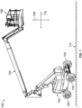
- FIG. 1 illustrates an isometric view of a lift system 100, according to an example of the present disclosure.
- the lift system includes a base 102 and a passenger basket 106, with one or more arms 104 that extend between the base 102 and the basket 106.
- the lift system 100 may be a scissor lift system, or the like, that moves occupants and/or equipment between different elevations.
- the lift system 100 is a boom lift system, and the arm(s) 104 is controlled to move the passenger basket 106 in a vertical direction 108 (between a ground surface 112 and different elevations), and a horizontal or lateral direction 110.
- the base 102 can include wheels 105 that can be controlled to move the lift system 100 in the horizontal direction 110.
- FIG. 2 illustrates a simplified top view of the passenger basket 106, in according to an example of the present disclosure.
- the passenger basket 106 includes a basket frame 204 that is coupled with the arm (not shown in Figure 2 ) at a joint 202.
- the passenger basket 106 includes an interior region 206 that is inside of the basket frame 204.
- one or more occupants and/or equipment may be positioned within the interior region 206 of the basket frame 204 to move the occupants and/or equipment to different elevations.
- the passenger basket 106 includes a gate 210 that is arranged to move between an open position and a closed position (shown in Figure 2 ) in a direction of rotation 212.
- the gate 210 may have an alternative arrangement such that the gate 210 moves in one or more different directions between the open and closed positions.
- the lift system 100 also includes a control system 220.
- the control system 220 is positioned within the passenger basket 106, but in alternative examples, the control system 220, or one or more components of the control system 220, may be disposed at other locations of the lift system, such as at the base 102.
- FIG. 3 illustrates a schematic of one example of the control system 220.
- the control system 220 includes a control unit or controller 222 having one or more processors, such as one or more microprocessors, field programmable gate arrays, integrated circuits, and/or the like.
- the controller 222 may include a single processor or multiple processors. All operations can be performed by each processor, or each processor may perform at least one different operation than one or more (or all) other processors.
- the control system 220 includes one or more sensors 224.
- the one or more sensors 224 may include a position sensor, a camera (e.g., a still camera, a video camera, an ergonomic camera, etc.), a pressure sensor, an ultrasonic sensor, a collision sensor, an infrared sensor, and/or the like.
- the one or more sensors 224 may be positioned at one or more locations of the passenger basket 106, may be operably coupled with the passenger basket 106, may be disposed outside of the basket 106, or any combination therein.
- the one or more sensors 224 may be referred to as occupant detector sensors.
- the sensors 224 may sense or otherwise detect data associated with occupants and/or other loads (for example, equipment, materials, etc.) that are positioned within the passenger basket 106 such as, but not limited to, a number of occupants that are inside the basket 106, a location of each of the occupants within the interior region 206 of the passenger basket 106 (for example, relative to each other occupant, relative to the gate 210, etc.), a number of occupants that are disposed outside of the passenger basket 106 (for example, such as an occupant that has moved outside of the basket frame 204), a location of the equipment within the basket 106, a weight of the other loads, a total weight of the occupants and the other loads, and/or the like.
- loads for example, equipment, materials, etc.
- the control system 220 also includes one or more input and/or output devices 226 (shown as I/O Device(s) in Figure 3 ).
- the lift system 100 can be manually operated by receiving instruction signals from the input/output devices 226 that can represent a touchscreen, a joystick, a keyboard, a switch, a wheel, a microphone, a display, a monitor, a speaker, a light, or the like.
- control system 220 also includes a communication device 228 that can include transceiving hardware (for example, antennas, wires, cables, modems, codecs, or the like) that can wirelessly communicate signals or communicate signals described herein via wired connections.
- the communication device 228 may communicate with the one or more occupants and/or operators positioned within the passenger basket 106, with one or more operators positioned proximate to the base 102 of the lift system 100, with one or more operators at a control center (not shown), and/or the like.
- the control system 220 also includes a power device 230, that can be or include one or more batteries, fuel cells, or the like, that may provide power to one or more systems and/or components of the lift system 100 (for example, propulsion loads, auxiliary loads, etc.).
- a power device 230 can be or include one or more batteries, fuel cells, or the like, that may provide power to one or more systems and/or components of the lift system 100 (for example, propulsion loads, auxiliary loads, etc.).
- the gate 210 may be moved from a closed position to an open position, such as to allow occupants and/or equipment to move into and/or out of the interior region 206 of the passenger basket 106. In one example, prior to the passenger basket 106 leaving the ground surface, or moving away from the ground surface, the gate 210 may be moved to a closed position, such as to contain the occupants and/or equipment within the interior region 206 of the passenger basket 106.
- the gate 210 may be moved to an open position to allow the occupants to move out of the interior region 206 of the passenger basket 106.
- the occupant may need to move to a portion of a structure that is being repaired that is at a location that the passenger basket is unable to reach.
- the passenger basket 106 also includes safety anchors 214A-E that are disposed at different locations around the basket frame 204.
- the passenger basket 106 includes four safety anchors 214A-D that are disposed at interior locations of the basket frame 204 (for example, within the interior region 206 of the passenger basket), and two safety anchors 214E-F that are disposed at exterior locations of the basket frame 204 (for example, outside of the basket frame).
- Each of the safety anchors 214A-F may be shaped and/or sized to receive a mating component, such as a safety key, that secures or anchors the one or more occupants to the passenger basket 106.
- a first end of a safety strap or lanyard may be operably coupled with at least one of the occupants (for example, attached to the occupant such as by a harness, a carabiner, or the like), and a second end of the safety strap may be operably coupled with a safety key.
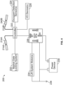
- FIG. 4 illustrates a schematic of a lift system 200, according to an example of the present disclosure.
- the controller 222 is electrically coupled with the input/output device(s) 226, a locking system 232 of the basket gate (for example, an electronic and/or mechanical locking system that can control whether the gate can be opened and/or closed), the one or more sensors 224 (such as the occupant detector sensors), one or more lift system motors 234 (for example, motors that control movement of the passenger basket and/or the base 102 of the lift system 100), and the power device 230 via a relay 236.
- the one or more lift system motors 234, the power device 230, and the relay 236 are also electrically coupled with an electrical ground 238.
- the schematic shown in Figure 4 is for illustrative purposes only.
- the lift system 200 have an alternative configuration, may include one or more additional electrical components, may be devoid one or more components shown, and/or the like.
- the controller 222 is also electrically coupled with a first safety anchor 214A and a second safety anchor 214B. In other examples, the controller may be electrically coupled with three or more safety anchors of the passenger basket 106.
- the first safety anchor 214A is coupled with a first safety key 240A
- the second safety anchor 214B is coupled with a second safety key 240B.
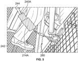
- FIG 5 illustrates a partial magnified view of the safety key 240A that is coupled with the first safety anchor 214A, according to an example of the present disclosure.
- the safety key 240A and the safety anchor 214 provide a connection assembly for a fall protection system 280 that is configured to prevent an individual from falling from the passenger basket 106 of the lift system 100.
- the safety key 240A is operably coupled with a first end of a safety strap 244 or safety lanyard.
- a second end of the safety strap 244 may be fastened or coupled with an occupant 242 of the passenger basket 106. While the occupant or operator is anchored to the safety anchor of the passenger basket 106 via the safety key 240A, the safety of the occupant increases relative to the occupant not being secured or tethered to the safety anchor via the safety key.
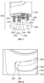
- FIG. 6 illustrates an isometric exploded view of a connection assembly 300 for a fall protection system, according to an example of the present disclosure.
- the connection assembly 300 includes a connector 302 that is configured to removably retain a coupler 304.
- the connector 302 provides the safety anchor 214A shown in Figures 4 and 5
- the coupler 304 provides the safety key 240A shown in Figures 4 and 5 .
- the connector 302 includes a support plate 306 coupled to a base cylinder 308, which, in turn, is coupled to an intermediate disk 310.
- a pin disk 312 is coupled to the intermediate disk 310.
- a retaining plate 314 is coupled to the pin disk 312.
- a cap 316 is coupled to the retaining plate 314.
- An inner sub-assembly 303 includes the pin disk 312 and the intermediate disk 310. As described herein, the inner sub-assembly 303 is configured to rotate relative to a shell housing 402 (shown in Figure 10 ) to allow the coupler 304 to be selectively connected and disconnected form the connector 302.
- FIG 7 illustrates an isometric view of the support plate 306 disconnected from the base cylinder 308, according to an example of the present disclosure.
- fasteners 318 extend from the cap 316 to the support plate 306 to secure the connector 302 together.
- the fasteners 318 can be screws, bolts, or the like. As shown, two fasteners 318 can be used. Optionally, a single fastener can be used, or three or more fasteners can be used.
- the fasteners 318 are retained by conforming through-holes 320 that pass through the cap 316, and conforming retaining recesses 322 formed in and/or passing through the support plate 306. In this manner, the cap 316 and the support plate 306 can be fixed in relation to one another.
- the cap 316 may not rotate relative to the support plate 306.
- the fasteners 318 pass through channels 324 that pass through the base cylinder 308.
- the fasteners 318 pass through through-holes 326 formed in the retaining plate 314.
- the cap 316, the support plate 306, the base cylinder 308, and the retaining plate 314 may remain fixed (for example, rotationally constrained) in relation to one another.
- the fasteners 318 pass through open spaces formed within the intermediate disk 310 and the pin disk 312. As such, the intermediate disk 310 and the pin disk 312 can rotate a limited range about a longitudinal axis 330 of the connector 302.
- springs 332 extend within the connector 302.
- the springs 332 have lower ends 334 that abut into the base cylinder 308. Ends (such as upper ends) opposite from the lower ends abut into pins 336 retained within the pin disk 312.
- each spring 332 is coupled to a respective pin 336.
- Figure 6 shows a pin 336.
- An additional pin 336 can also retained by the pin disk 312.
- Figure 8 illustrates an isometric view of the intermediate disk 310 having a button 338, according to an example of the present disclosure.
- the intermediate disk 310 includes a main body 340 having a radial channel 342 formed therein.
- the button 338 includes a pivot end 346 that is pivotally secured within the channel 342, such as by a connection fastener, such as a pin, (not shown), which can be spring-biased.
- the pivot end 346 connects to a free end 350 that can be selectively pressed inward.
- the spring-biased connection fastener outwardly biases the button 338 to be flush with an outer surface of the intermediate disk 310.
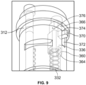
- Figure 9 illustrates an isometric internal view of a pin 336 within the pin disk 312, according to an example of the present disclosure.
- the pin 336 includes an extension body 360, which can be wedge shaped, and configured to be slidably retained within a conforming reciprocal opening 362 formed in the pin disk 312.
- the spring 332 abuts into a lower end 364 of the extension body 360 and acts to bias an end, such as an upper end 366, of the extension body 360 through a conforming reciprocal opening 368 of the retaining plate 314.
- the pin 336 also includes a protuberance 370, such as a post, barb, clasp, nub, or the like that extends outwardly from the extension body 360 and through a track 372 formed through the pin disk 312.
- a protuberance 370 such as a post, barb, clasp, nub, or the like that extends outwardly from the extension body 360 and through a track 372 formed through the pin disk 312.
- the cap 316 includes opposed openings 380 formed therethrough.
- the coupler 304 includes a main body 390 that is configured to extend above the cap 316.
- Extension necks 392 extend downwardly from the main body 390.
- Each neck 392 connects to a radial hook 393 that radially extends below that main body 390.
- the radial hook 393 includes a tip 394 that extends below the main body 390, and is separated from the main body by a gap 396.
- the openings 380 are configured to conform to the shape of the hooks 393 and allow the hooks 393 to pass therethrough.
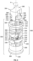
- Figure 10 illustrates an isometric view of the connector 302, according to an example of the present disclosure.
- the button 338 (shown in Figure 8 ) is not shown in Figure 10 .
- the connector 302 has a cylindrical shape. That is, the connector 302 resides within a cylindrical envelope.
- the button 338 is pivotally secured within the channel 342, such as by a connection fastener, such as a pin, (not shown), which can be spring-biased.
- the pivot end 346 connects to a free end 350 that can be selectively pressed inward.
- the spring-biased connection fastener outwardly biases the button 338 to be flush with an outer surface of the intermediate disk 310.
- a shell housing 402 extends around the base cylinder 308, the intermediate disk 310, and the pin disk 312. That is, the connector 302 includes the shell housing 402.
- the shell housing 402 includes a helical track 404 formed therethrough.
- the helical track 404 includes an inlet 408 that extends to the retaining plate 314.
- the inlet 408 can be a straight segment defined by interior edges of the shell housing 402.
- the inlet 408 connects to an upper edge 410 that helically angles downwardly to a vertical edge 412.
- the vertical edge 412 connects to a lower ledge 414, which, in turn, connects to an upwardly curved edge 416 that connects to the inlet 408.
- the protuberance 370 abuts against the upper edge 410 proximate to the inlet 408.
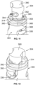
- Figure 11 illustrates an isometric top view of the coupler 304 aligned with the openings 380 of the cap 316 of the connector 302, according to an example of the present disclosure.
- Figure 12 illustrates an isometric top view of the coupler 304 secured to the connector 302.
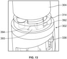
- Figure 13 illustrates an isometric top view of the coupler 304 secured to the connector 302. Referring to Figures 6-13 , in order to secure the coupler 304 to the connector 302, the hooks 393 of the coupling are axially aligned with the openings 380.
- the free end 350 of the button 338 is inwardly depressed with the pivot end 346 abutting into a wall 420 defining an end of the channel 342.
- the user may rotate the intermediate disk 310 in the direction opposite from arc A.
- the intermediate disk 310 rotates past the blunt ends 395 of the hooks 393, the upper ends 366 are forced upwardly through the openings 368 and abut against the blunt ends 395, with the tips 394 of the hooks 393 trapped underneath the retaining plate, thereby locking the coupler 304 to the connector 302.
- Such motion can also emit an audible click, thereby indicating that the coupler 304 is securely connected to the connector 302.
- a user may engage the button 338 to rotate the intermediate disk 310 relative to the shell housing 402 as described, so that the button retreats into the openings 368, and the hooks 393 axially align with the openings 380 of the cap 316.
- the coupler 304 can then be removed from the connector 302.
- connection assembly 300 for a fall protection system 280.
- the connection assembly 300 includes the connector 302 including the shell housing 402 and the inner sub-assembly 303.
- the inner sub-assembly 303 is rotatable relative to the shell housing 402.
- the coupler 304 is configured to be selectively connected and disconnected from the connector 302.
- the inner sub-assembly 303 is configured to be rotated in relation to the shell housing 402 (that is, the shell housing 402 can be manipulated and rotated in relation to the inner sub-assembly 303, or vice versa) to selectively connect the coupler 304 to and disconnect the coupler 304 from the connector 302.
- connection assembly 300 includes the connector 302 and the coupler 304, which can be quickly, easily, and effectively selectively connected and disconnected from the connector 302 through rotational motion. It has been found that an individual wearing gloves, for example, can efficiently and effectively perform such operations.
- the shell housing 402 is rotated relative to an inner sub-assembly 303 (or vice versa), which includes the intermediate disk 310 and the pin disk 312, for example. Such rotational motion retracts the pins 336, as described herein.
- a safety lanyard may be attached to the connector 302 or the coupler 304.
- the cylindrical shape of the connector 302 allows for operation that is ergonomically improved in contrast to prior devices.
- Current known devices typically require intricate interaction in order to connect and disconnect components.
- examples of the present disclosure provide easy-to-use components that can be selectively connected and disconnected from one another via simple rotational motion.
- examples of the present disclosure provide a method for a fall protection system of a lift system.
- the method includes connecting a coupler to a connector, and disconnecting the coupler from the connector by rotating an inner sub-assembly of the connector relative to the shell housing.
- examples of the present disclosure provide an improved connection device for a fall protection system.
- Examples of the present disclosure provide a connection assembly that is easily and effectively manipulated by an individual. Further, examples of the present disclosure provide a connection assembly that can be easily and effectively grasped, engaged, and manipulated with gloves.
Landscapes
- Health & Medical Sciences (AREA)
- General Health & Medical Sciences (AREA)
- Business, Economics & Management (AREA)
- Emergency Management (AREA)
- Life Sciences & Earth Sciences (AREA)
- Engineering & Computer Science (AREA)
- Geology (AREA)
- Mechanical Engineering (AREA)
- Structural Engineering (AREA)
- Details Of Connecting Devices For Male And Female Coupling (AREA)
- Emergency Lowering Means (AREA)
Abstract
Description
- Examples of the present disclosure generally relate to personal fall protection systems and methods, and more particularly, to a connection assembly for a fall protection system.
- Regulations exist that require individuals using a lift system (for example, a boom lift, a scissor lift, etc.) to wear a fall protection harness that is to be connected to the lift system. For example, if an occupant falls from the lift, the fall distance is limited by a length of a safety strap that extends between the protection harness worn by the operator and the lift basket. The safety strap may have a safety key disposed at one end of the strap (that is opposite the end of the strap that is tethered to the harness of the operator) that may be coupled with one or more safety anchors of the lift basket. The safety anchors may be electrically coupled with a control system of the lift system, and a verification process may require confirmation that each safety key is securely coupled with at least one safety anchor before movement of the lift system is allowed.
- Known connection devices for fall protection connection systems may be difficult to attach or detach, such as if an individual is wearing gloves. In particular, gloves may interfere with manipulation and engagement of the safety equipment. In short, known connection devices may not allow for quick and easy manipulation to connect and disconnect.
- A need exists for an improved connection device for a fall protection system. A need exists for a connection device that is easily and effectively manipulated by an individual. Further, a need exists for a connection device that can be easily and effectively grasped, engaged, and manipulated with gloves.
- With those needs in mind, certain examples of the present disclosure provide a connection assembly for a fall protection system. The connection assembly includes a connector including a shell housing and an inner sub-assembly. The inner sub-assembly is rotatable relative to the shell housing. A coupler is configured to be selectively connected to and disconnected from the connector. The inner sub-assembly is configured to be rotated in relation to the shell housing to selectively connect the coupler to and disconnect the coupler from the connector.
- In at least one example, the connector is configured to be coupled to a basket of a lift system, and the coupler is configured to be coupled to a safety harness worn by an individual.
- As an example, the connector includes a support plate, a base cylinder coupled to the support plate, an intermediate disk coupled to the base cylinder, a pin disk coupled to the intermediate disk, a retaining plate coupled to the pin disk, and a cap coupled to the retaining plate.
- The pin disk retains one or more pins. The pins are moveable in relation to the pin disk. The the one or more pins have an end configured to move into and out of a reciprocal opening of the retaining plate. In at least one example, one or more springs are coupled to the one or more pins. The one or more springs bias the one or more pins into and through the reciprocal opening. In at least one example, the one or more pins include a protuberance extending outwardly through a track formed through the pin disk.
- In at least one example, the shell housing includes a helical track. The protuberance includes at least a portion disposed within the helical track. The protuberance is moveable through the helical track.
- In at least one example, the intermediate disk includes a button configured to be engaged to rotate the inner sub-assembly relative to the shell housing.
- As an example, the coupler includes a main body configured to extend above the cap when the coupler is connected to the connector. One or more necks extend downwardly from the main body. One or more radial hooks connect to the one or more necks. The one or more radial hooks include a tip separated from the main body by a gap.
- In at least one example, the inner sub-assembly comprises the pin disk and the intermediate disk.
- Certain examples of the present disclosure provide a lift system including a basket configured to receive one or more passengers within an interior region, and a fall protection system including a connection assembly, as described herein.
-
-
Figure 1 illustrates an isometric view of a lift system, according to an example of the present disclosure. -
Figure 2 illustrates a simplified top view of a passenger basket of a lift system, according to an example of the present disclosure. -
Figure 3 illustrates a schematic of a controller of the passenger basket shown inFigure 2 , according to an example of the present disclosure. -
Figure 4 illustrates a schematic of a lift system, according to an example of the present disclosure; -
Figure 5 illustrates a partial view of a safety key operably coupled with a safety anchor of a passenger basket, according to an example of the present disclosure. -
Figure 6 illustrates an isometric exploded view of a connection assembly for a fall protection system, according to an example of the present disclosure. -
Figure 7 illustrates an isometric view of a support plate disconnected from a base cylinder, according to an example of the present disclosure. -
Figure 8 illustrates an isometric view of an intermediate disk having a button, according to an example of the present disclosure. -
Figure 9 illustrates an isometric internal view of a pin within a pin disk, according to an example of the present disclosure. -
Figure 10 illustrates an isometric view of a connector, according to an example of the present disclosure. -
Figure 11 illustrates an isometric top view of a coupling aligned with openings of a cap of the connector, according to an example of the present disclosure. -
Figure 12 illustrates an isometric top view of the coupling connecting to the connector, according to an example of the present disclosure. -
Figure 13 illustrates an isometric top view of the coupling secured to the connector, according to an example of the present disclosure. - The foregoing summary, as well as the following detailed description of certain examples will be better understood when read in conjunction with the appended drawings. As used herein, an element or step recited in the singular and preceded by the word "a" or "an" should be understood as not necessarily excluding the plural of the elements or steps. Further, references to "one example" are not intended to be interpreted as excluding the existence of additional examples that also incorporate the recited features. Moreover, unless explicitly stated to the contrary, examples "comprising" or "having" an element or a plurality of elements having a particular condition can include additional elements not having that condition.
- As described herein, examples of the present disclosure provide a connection assembly for a fall protection system. The connection assembly provides a quick attach connection system including a coupler and a connector configured to be selectively connected and disconnected from one another via a press and twist motion. The connection assembly can be easily connected or disconnected, even if an individual is wearing gloves.
-
Figure 1 illustrates an isometric view of alift system 100, according to an example of the present disclosure. The lift system includes abase 102 and apassenger basket 106, with one ormore arms 104 that extend between thebase 102 and thebasket 106. In other examples, thelift system 100 may be a scissor lift system, or the like, that moves occupants and/or equipment between different elevations. In the illustrated example, thelift system 100 is a boom lift system, and the arm(s) 104 is controlled to move thepassenger basket 106 in a vertical direction 108 (between aground surface 112 and different elevations), and a horizontal orlateral direction 110. Additionally, thebase 102 can includewheels 105 that can be controlled to move thelift system 100 in thehorizontal direction 110. -
Figure 2 illustrates a simplified top view of thepassenger basket 106, in according to an example of the present disclosure. Thepassenger basket 106 includes abasket frame 204 that is coupled with the arm (not shown inFigure 2 ) at a joint 202. Thepassenger basket 106 includes aninterior region 206 that is inside of thebasket frame 204. For example, one or more occupants and/or equipment may be positioned within theinterior region 206 of thebasket frame 204 to move the occupants and/or equipment to different elevations. - The
passenger basket 106 includes agate 210 that is arranged to move between an open position and a closed position (shown inFigure 2 ) in a direction ofrotation 212. In another example, thegate 210 may have an alternative arrangement such that thegate 210 moves in one or more different directions between the open and closed positions. - The
lift system 100 also includes acontrol system 220. In the illustrated example, thecontrol system 220 is positioned within thepassenger basket 106, but in alternative examples, thecontrol system 220, or one or more components of thecontrol system 220, may be disposed at other locations of the lift system, such as at thebase 102. -
Figure 3 illustrates a schematic of one example of thecontrol system 220. Thecontrol system 220 includes a control unit orcontroller 222 having one or more processors, such as one or more microprocessors, field programmable gate arrays, integrated circuits, and/or the like. In one example, thecontroller 222 may include a single processor or multiple processors. All operations can be performed by each processor, or each processor may perform at least one different operation than one or more (or all) other processors. - In at least one example, the
control system 220 includes one ormore sensors 224. In one or more examples, the one ormore sensors 224 may include a position sensor, a camera (e.g., a still camera, a video camera, an ergonomic camera, etc.), a pressure sensor, an ultrasonic sensor, a collision sensor, an infrared sensor, and/or the like. The one ormore sensors 224 may be positioned at one or more locations of thepassenger basket 106, may be operably coupled with thepassenger basket 106, may be disposed outside of thebasket 106, or any combination therein. In at least one example, the one ormore sensors 224 may be referred to as occupant detector sensors. For example, thesensors 224 may sense or otherwise detect data associated with occupants and/or other loads (for example, equipment, materials, etc.) that are positioned within thepassenger basket 106 such as, but not limited to, a number of occupants that are inside thebasket 106, a location of each of the occupants within theinterior region 206 of the passenger basket 106 (for example, relative to each other occupant, relative to thegate 210, etc.), a number of occupants that are disposed outside of the passenger basket 106 (for example, such as an occupant that has moved outside of the basket frame 204), a location of the equipment within thebasket 106, a weight of the other loads, a total weight of the occupants and the other loads, and/or the like. - The
control system 220 also includes one or more input and/or output devices 226 (shown as I/O Device(s) inFigure 3 ). The lift system 100 (shown inFigure 1 ) can be manually operated by receiving instruction signals from the input/output devices 226 that can represent a touchscreen, a joystick, a keyboard, a switch, a wheel, a microphone, a display, a monitor, a speaker, a light, or the like. - In one or more examples, the
control system 220 also includes acommunication device 228 that can include transceiving hardware (for example, antennas, wires, cables, modems, codecs, or the like) that can wirelessly communicate signals or communicate signals described herein via wired connections. Thecommunication device 228 may communicate with the one or more occupants and/or operators positioned within thepassenger basket 106, with one or more operators positioned proximate to thebase 102 of thelift system 100, with one or more operators at a control center (not shown), and/or the like. - The
control system 220 also includes apower device 230, that can be or include one or more batteries, fuel cells, or the like, that may provide power to one or more systems and/or components of the lift system 100 (for example, propulsion loads, auxiliary loads, etc.). - Returning again to
Figure 2 , in one or more examples, thegate 210 may be moved from a closed position to an open position, such as to allow occupants and/or equipment to move into and/or out of theinterior region 206 of thepassenger basket 106. In one example, prior to thepassenger basket 106 leaving the ground surface, or moving away from the ground surface, thegate 210 may be moved to a closed position, such as to contain the occupants and/or equipment within theinterior region 206 of thepassenger basket 106. In another example, after thepassenger basket 106 has been moved to an elevated position (for example, to perform maintenance on a structure, such as a building, an aircraft system, utility equipment, or the like), thegate 210 may be moved to an open position to allow the occupants to move out of theinterior region 206 of thepassenger basket 106. For example, the occupant may need to move to a portion of a structure that is being repaired that is at a location that the passenger basket is unable to reach. - The
passenger basket 106 also includes safety anchors 214A-E that are disposed at different locations around thebasket frame 204. In the illustrated example, thepassenger basket 106 includes foursafety anchors 214A-D that are disposed at interior locations of the basket frame 204 (for example, within theinterior region 206 of the passenger basket), and twosafety anchors 214E-F that are disposed at exterior locations of the basket frame 204 (for example, outside of the basket frame). Each of the safety anchors 214A-F may be shaped and/or sized to receive a mating component, such as a safety key, that secures or anchors the one or more occupants to thepassenger basket 106. For example, a first end of a safety strap or lanyard (not shown) may be operably coupled with at least one of the occupants (for example, attached to the occupant such as by a harness, a carabiner, or the like), and a second end of the safety strap may be operably coupled with a safety key. -
Figure 4 illustrates a schematic of alift system 200, according to an example of the present disclosure. Thecontroller 222 is electrically coupled with the input/output device(s) 226, alocking system 232 of the basket gate (for example, an electronic and/or mechanical locking system that can control whether the gate can be opened and/or closed), the one or more sensors 224 (such as the occupant detector sensors), one or more lift system motors 234 (for example, motors that control movement of the passenger basket and/or thebase 102 of the lift system 100), and thepower device 230 via arelay 236. The one or morelift system motors 234, thepower device 230, and therelay 236 are also electrically coupled with anelectrical ground 238. The schematic shown inFigure 4 is for illustrative purposes only. In another example, thelift system 200 have an alternative configuration, may include one or more additional electrical components, may be devoid one or more components shown, and/or the like. - In the illustrated example, the
controller 222 is also electrically coupled with afirst safety anchor 214A and asecond safety anchor 214B. In other examples, the controller may be electrically coupled with three or more safety anchors of thepassenger basket 106. Thefirst safety anchor 214A is coupled with afirst safety key 240A, and thesecond safety anchor 214B is coupled with asecond safety key 240B. -
Figure 5 illustrates a partial magnified view of thesafety key 240A that is coupled with thefirst safety anchor 214A, according to an example of the present disclosure. Referring toFigures 1-5 , thesafety key 240A and the safety anchor 214 provide a connection assembly for afall protection system 280 that is configured to prevent an individual from falling from thepassenger basket 106 of thelift system 100. Thesafety key 240A is operably coupled with a first end of asafety strap 244 or safety lanyard. A second end of thesafety strap 244 may be fastened or coupled with anoccupant 242 of thepassenger basket 106. While the occupant or operator is anchored to the safety anchor of thepassenger basket 106 via thesafety key 240A, the safety of the occupant increases relative to the occupant not being secured or tethered to the safety anchor via the safety key. -
Figure 6 illustrates an isometric exploded view of aconnection assembly 300 for a fall protection system, according to an example of the present disclosure. Theconnection assembly 300 includes aconnector 302 that is configured to removably retain acoupler 304. In at least one example, theconnector 302 provides thesafety anchor 214A shown inFigures 4 and5 , while thecoupler 304 provides thesafety key 240A shown inFigures 4 and5 . - The
connector 302 includes asupport plate 306 coupled to abase cylinder 308, which, in turn, is coupled to anintermediate disk 310. Apin disk 312 is coupled to theintermediate disk 310. A retainingplate 314 is coupled to thepin disk 312. Acap 316 is coupled to the retainingplate 314. Aninner sub-assembly 303 includes thepin disk 312 and theintermediate disk 310. As described herein, theinner sub-assembly 303 is configured to rotate relative to a shell housing 402 (shown inFigure 10 ) to allow thecoupler 304 to be selectively connected and disconnected form theconnector 302. -
Figure 7 illustrates an isometric view of thesupport plate 306 disconnected from thebase cylinder 308, according to an example of the present disclosure. Referring toFigures 6 and7 ,fasteners 318 extend from thecap 316 to thesupport plate 306 to secure theconnector 302 together. Thefasteners 318 can be screws, bolts, or the like. As shown, twofasteners 318 can be used. Optionally, a single fastener can be used, or three or more fasteners can be used. Thefasteners 318 are retained by conforming through-holes 320 that pass through thecap 316, and conforming retainingrecesses 322 formed in and/or passing through thesupport plate 306. In this manner, thecap 316 and thesupport plate 306 can be fixed in relation to one another. For example, thecap 316 may not rotate relative to thesupport plate 306. Similarly, thefasteners 318 pass throughchannels 324 that pass through thebase cylinder 308. Further, thefasteners 318 pass through through-holes 326 formed in the retainingplate 314. As such, thecap 316, thesupport plate 306, thebase cylinder 308, and the retainingplate 314 may remain fixed (for example, rotationally constrained) in relation to one another. - The
fasteners 318 pass through open spaces formed within theintermediate disk 310 and thepin disk 312. As such, theintermediate disk 310 and thepin disk 312 can rotate a limited range about alongitudinal axis 330 of theconnector 302. - As shown, springs 332 extend within the
connector 302. Thesprings 332 havelower ends 334 that abut into thebase cylinder 308. Ends (such as upper ends) opposite from the lower ends abut intopins 336 retained within thepin disk 312. For example, eachspring 332 is coupled to arespective pin 336.Figure 6 shows apin 336. Anadditional pin 336 can also retained by thepin disk 312. -
Figure 8 illustrates an isometric view of theintermediate disk 310 having abutton 338, according to an example of the present disclosure. Theintermediate disk 310 includes amain body 340 having aradial channel 342 formed therein. Thebutton 338 includes apivot end 346 that is pivotally secured within thechannel 342, such as by a connection fastener, such as a pin, (not shown), which can be spring-biased. Thepivot end 346 connects to afree end 350 that can be selectively pressed inward. The spring-biased connection fastener outwardly biases thebutton 338 to be flush with an outer surface of theintermediate disk 310. -
Figure 9 illustrates an isometric internal view of apin 336 within thepin disk 312, according to an example of the present disclosure. Referring toFigures 6 and9 , thepin 336 includes anextension body 360, which can be wedge shaped, and configured to be slidably retained within a conformingreciprocal opening 362 formed in thepin disk 312. Thespring 332 abuts into alower end 364 of theextension body 360 and acts to bias an end, such as anupper end 366, of theextension body 360 through a conformingreciprocal opening 368 of the retainingplate 314. Thepin 336 also includes aprotuberance 370, such as a post, barb, clasp, nub, or the like that extends outwardly from theextension body 360 and through atrack 372 formed through thepin disk 312. When thespring 332 biases theupper end 366 of theextension body 360 through theopening 368 of the retainingplate 314, anupper surface 374 of theprotuberance 370 abuts against alower surface 376 of the retainingplate 314 to ensure that thepin 336 does not eject through the retainingplate 314. - Referring again to
Figure 6 , thecap 316 includes opposedopenings 380 formed therethrough. Thecoupler 304 includes amain body 390 that is configured to extend above thecap 316.Extension necks 392 extend downwardly from themain body 390. Eachneck 392 connects to aradial hook 393 that radially extends below thatmain body 390. Theradial hook 393 includes atip 394 that extends below themain body 390, and is separated from the main body by agap 396. Theopenings 380 are configured to conform to the shape of thehooks 393 and allow thehooks 393 to pass therethrough. -
Figure 10 illustrates an isometric view of theconnector 302, according to an example of the present disclosure. The button 338 (shown inFigure 8 ) is not shown inFigure 10 . As shown, theconnector 302 has a cylindrical shape. That is, theconnector 302 resides within a cylindrical envelope. - Referring to
Figures 8 and10 , thebutton 338 is pivotally secured within thechannel 342, such as by a connection fastener, such as a pin, (not shown), which can be spring-biased. Thepivot end 346 connects to afree end 350 that can be selectively pressed inward. The spring-biased connection fastener outwardly biases thebutton 338 to be flush with an outer surface of theintermediate disk 310. - Referring to
Figures 6 and10 , ashell housing 402 extends around thebase cylinder 308, theintermediate disk 310, and thepin disk 312. That is, theconnector 302 includes theshell housing 402. Theshell housing 402 includes ahelical track 404 formed therethrough. Thehelical track 404 includes aninlet 408 that extends to the retainingplate 314. Theinlet 408 can be a straight segment defined by interior edges of theshell housing 402. Theinlet 408 connects to anupper edge 410 that helically angles downwardly to avertical edge 412. Thevertical edge 412, in turn, connects to alower ledge 414, which, in turn, connects to an upwardlycurved edge 416 that connects to theinlet 408. As shown, theprotuberance 370 abuts against theupper edge 410 proximate to theinlet 408. -
Figure 11 illustrates an isometric top view of thecoupler 304 aligned with theopenings 380 of thecap 316 of theconnector 302, according to an example of the present disclosure.Figure 12 illustrates an isometric top view of thecoupler 304 secured to theconnector 302.Figure 13 illustrates an isometric top view of thecoupler 304 secured to theconnector 302. Referring toFigures 6-13 , in order to secure thecoupler 304 to theconnector 302, thehooks 393 of the coupling are axially aligned with theopenings 380. Thefree end 350 of thebutton 338 is inwardly depressed with thepivot end 346 abutting into awall 420 defining an end of thechannel 342. An individual then rotates theintermediate disk 310 about thelongitudinal axis 330 in the direction of arc A. During such rotational motion, theprotuberance 370 slides underneath theupper edge 410 of the track, which pulls thepins 336 downwardly, thereby compressing thesprings 332. Such rotational motion continues until the upper ends 366 of thepins 336 recede into theopenings 368 of the retainingplate 314. Lower surfaces of thehooks 393 can then be positioned on the top surface of the retainingplate 314 over the recessed upper ends 366. The user may then release thebutton 338, and the force of thecompressed springs 332 forces theintermediate disk 310 to rotationally retreat in a direction opposite from arc A. Optionally, the user may rotate theintermediate disk 310 in the direction opposite from arc A. Once theintermediate disk 310 rotates past the blunt ends 395 of thehooks 393, the upper ends 366 are forced upwardly through theopenings 368 and abut against the blunt ends 395, with thetips 394 of thehooks 393 trapped underneath the retaining plate, thereby locking thecoupler 304 to theconnector 302. Such motion can also emit an audible click, thereby indicating that thecoupler 304 is securely connected to theconnector 302. - In order to disconnect the
coupler 304 from theconnector 302, a user may engage thebutton 338 to rotate theintermediate disk 310 relative to theshell housing 402 as described, so that the button retreats into theopenings 368, and thehooks 393 axially align with theopenings 380 of thecap 316. Thecoupler 304 can then be removed from theconnector 302. - As described herein, examples of the present disclosure provide a
connection assembly 300 for afall protection system 280. Theconnection assembly 300 includes theconnector 302 including theshell housing 402 and theinner sub-assembly 303. Theinner sub-assembly 303 is rotatable relative to theshell housing 402. Thecoupler 304 is configured to be selectively connected and disconnected from theconnector 302. Theinner sub-assembly 303 is configured to be rotated in relation to the shell housing 402 (that is, theshell housing 402 can be manipulated and rotated in relation to theinner sub-assembly 303, or vice versa) to selectively connect thecoupler 304 to and disconnect thecoupler 304 from theconnector 302. - As described herein, the
connection assembly 300 includes theconnector 302 and thecoupler 304, which can be quickly, easily, and effectively selectively connected and disconnected from theconnector 302 through rotational motion. It has been found that an individual wearing gloves, for example, can efficiently and effectively perform such operations. - In at least one example, the
shell housing 402 is rotated relative to an inner sub-assembly 303 (or vice versa), which includes theintermediate disk 310 and thepin disk 312, for example. Such rotational motion retracts thepins 336, as described herein. A safety lanyard may be attached to theconnector 302 or thecoupler 304. - The cylindrical shape of the
connector 302 allows for operation that is ergonomically improved in contrast to prior devices. Current known devices typically require intricate interaction in order to connect and disconnect components. In contrast, examples of the present disclosure provide easy-to-use components that can be selectively connected and disconnected from one another via simple rotational motion. - As described herein, examples of the present disclosure provide a method for a fall protection system of a lift system. The method includes connecting a coupler to a connector, and disconnecting the coupler from the connector by rotating an inner sub-assembly of the connector relative to the shell housing.
- Further, the disclosure comprises examples according to the following clauses:
- Clause 1: A connection assembly for a fall protection system, the connection assembly comprising:
- a connector including a shell housing and an inner sub-assembly, wherein the inner sub-assembly is rotatable relative to the shell housing; and
- a coupler configured to be selectively connected to and disconnected from the connector, wherein the inner sub-assembly is configured to be rotated in relation to the shell housing to selectively connect the coupler to and disconnect the coupler from the connector.
- Clause 2. The connection assembly of Clause 1, wherein the connector is configured to be coupled to a basket of a lift system, and wherein the coupler is configured to be coupled to a safety harness worn by an individual.
- Clause 3. The connection assembly of Clauses 1 or 2, wherein the connector comprises:
- a support plate;
- a base cylinder coupled to the support plate;
- an intermediate disk coupled to the base cylinder;
- a pin disk coupled to the intermediate disk;
- a retaining plate coupled to the pin disk; and
- a cap coupled to the retaining plate.
- Clause 4. The connection assembly of Clause 3, wherein the pin disk retains one or more pins, wherein the pins are moveable in relation to the pin disk, and wherein the one or more pins have an end configured to move into and out of a reciprocal opening of the retaining plate.
- Clause 5. The connection assembly of Clause 4, further comprising one or more springs coupled to the one or more pins, wherein the one or more springs bias the one or more pins into and through the reciprocal opening.
- Clause 6. The connection assembly of Clauses 4 or 5, wherein the one or more pins comprise a protuberance extending outwardly through a track formed through the pin disk.
-
Clause 7. The connection assembly of Clause 6, wherein the shell housing comprises a helical track, wherein the protuberance includes at least a portion disposed within the helical track, and wherein the protuberance is moveable through the helical track. - Clause 8. The connection assembly of any of Clauses 3-7, wherein the intermediate disk comprises a button configured to be engaged to rotate the inner sub-assembly relative to the shell housing.
- Clause 9. The connection assembly of any of Clauses 3-8, wherein the coupler comprises:
- a main body configured to extend above the cap when the coupler is connected to the connector;
- one or more necks extending downwardly from the main body; and
- one or more radial hooks connecting to the one or more necks, wherein the one or more radial hooks comprise a tip separated from the main body by a gap.
- Clause 10. The connection assembly of any of Clauses 3-9, wherein the inner sub-assembly comprises the pin disk and the intermediate disk.
- Clause 11. A lift system comprising:
- a basket configured to receive one or more passengers within an interior region;
- a fall protection system including a connection assembly, the connection assembly comprising:
- a connector including a shell housing and an inner sub-assembly, wherein the inner sub-assembly is rotatable relative to the shell housing, and wherein the connector is coupled to a basket of a lift system; and
- a coupler configured to be selectively connected to and disconnected from the connector, wherein the coupler is configured to be coupled to a safety harness worn by an individual, and wherein the inner sub-assembly is configured to be rotated in relation to the shell housing to selectively connect the coupler to and disconnect the coupler from the connector.
- Clause 12. The lift system of Clause 11, wherein the connector comprises:
- a support plate;
- a base cylinder coupled to the support plate;
- an intermediate disk coupled to the base cylinder;
- a pin disk coupled to the intermediate disk;
- a retaining plate coupled to the pin disk; and
- a cap coupled to the retaining plate.
- Clause 13. The lift system of Clause 12, wherein the pin disk retains one or more pins, wherein the pins are moveable in relation to the pin disk, and wherein the one or more pins have an end configured to move into and out of a reciprocal opening of the retaining plate.
- Clause 14. The lift system of Clause 13, wherein the connection assembly further comprises one or more springs coupled to the one or more pins, wherein the one or more springs bias the one or more pins into and through the reciprocal opening.
- Clause 15. The lift system of Clauses 13 or 14, wherein the one or more pins comprise a protuberance extending outwardly through a track formed through the pin disk.
- Clause 16. The lift system of Clause 15, wherein the shell housing comprises a helical track, wherein the protuberance includes at least a portion disposed within the helical track, and wherein the protuberance is moveable through the helical track.
- Clause 17. The lift system of any of Clauses 12-16, wherein the intermediate disk comprises a button configured to be engaged to rotate the inner sub-assembly relative to the shell housing.
- Clause 18. The lift system of Clause 17, wherein the coupler comprises:
- a main body configured to extend above the cap when the coupler is connected to the connector;
- one or more necks extending downwardly from the main body; and
- one or more radial hooks connecting to the one or more necks, wherein the one or more radial hooks comprise a tip separated from the main body by a gap.
- Clause 19. The lift system of any of Clauses 12-19, wherein the inner sub-assembly comprises the pin disk and the intermediate disk.
- Clause 20. A connection assembly for a fall protection system, the connection assembly comprising:
- a connector including a shell housing and an inner sub-assembly, wherein the inner sub-assembly is rotatable relative to the shell housing, wherein the shell housing comprises a helical track, and wherein the connector is configured to be coupled to a basket of a lift system, wherein the connector further comprises:
- a support plate;
- a base cylinder coupled to the support plate;
- an intermediate disk coupled to the base cylinder, wherein the intermediate disk comprises a button configured to be engaged to rotate the inner sub-assembly relative to the shell housing;
- a pin disk coupled to the intermediate disk, wherein the pin disk retains one or more pins, and wherein the pins are moveable in relation to the pin disk, wherein the one or more pins comprise a protuberance extending outwardly through a track formed through the pin disk, wherein the protuberance includes at least a portion disposed within the helical track, and wherein the protuberance is moveable through the helical track;
- one or more springs coupled to the one or more pins, wherein the one or more springs bias the one or more pins into and through the reciprocal opening;
- a retaining plate coupled to the pin disk, wherein the one or more pins have an end configured to move into and out of a reciprocal opening of the retaining plate; and
- a cap coupled to the retaining plate; and
- a coupler configured to be selectively connected to and disconnected from the connector, wherein the coupler is configured to be coupled to a safety harness worn by an individual, wherein the inner sub-assembly is configured to be rotated in relation to the shell housing to selectively connect the coupler to and disconnect the coupler from the connector, and wherein the coupler comprises:
- a main body configured to extend above the cap when the coupler is connected to the connector;
- one or more necks extending downwardly from the main body; and
- one or more radial hooks connecting to the one or more necks, wherein the one or more radial hooks comprise a tip separated from the main body by a gap.
- a connector including a shell housing and an inner sub-assembly, wherein the inner sub-assembly is rotatable relative to the shell housing, wherein the shell housing comprises a helical track, and wherein the connector is configured to be coupled to a basket of a lift system, wherein the connector further comprises:
- As described herein, examples of the present disclosure provide an improved connection device for a fall protection system. Examples of the present disclosure provide a connection assembly that is easily and effectively manipulated by an individual. Further, examples of the present disclosure provide a connection assembly that can be easily and effectively grasped, engaged, and manipulated with gloves.
- While various spatial and directional terms, such as top, bottom, lower, mid, lateral, horizontal, vertical, front and the like can be used to describe examples of the present disclosure, it is understood that such terms are merely used with respect to the orientations shown in the drawings. The orientations can be inverted, rotated, or otherwise changed, such that an upper portion is a lower portion, and vice versa, horizontal becomes vertical, and the like.
- As used herein, a structure, limitation, or element that is "configured to" perform a task or operation is particularly structurally formed, constructed, or adapted in a manner corresponding to the task or operation. For purposes of clarity and the avoidance of doubt, an object that is merely capable of being modified to perform the task or operation is not "configured to" perform the task or operation as used herein.
- It is to be understood that the above description is intended to be illustrative, and not restrictive. For example, the above-described examples (and/or aspects thereof) can be used in combination with each other. In addition, many modifications can be made to adapt a particular situation or material to the teachings of the various examples of the disclosure without departing from their scope. While the dimensions and types of materials described herein are intended to define the aspects of the various examples of the disclosure, the examples are by no means limiting and are exemplary examples. Many other examples will be apparent to those of skill in the art upon reviewing the above description. The scope of the various examples of the disclosure should, therefore, be determined with reference to the appended claims, along with the full scope of equivalents to which such claims are entitled. In the appended claims and the detailed description herein, the terms "including" and "in which" are used as the plain-English equivalents of the respective terms "comprising" and "wherein." Moreover, the terms "first," "second," and "third," etc. are used merely as labels, and are not intended to impose numerical requirements on their objects. Further, the limitations of the following claims are not written in means-plus-function format and are not intended to be interpreted based on 35 U.S.C. § 112(f), unless and until such claim limitations expressly use the phrase "means for" followed by a statement of function void of further structure.
- This written description uses examples to disclose the various examples of the disclosure, including the best mode, and also to enable any person skilled in the art to practice the various examples of the disclosure, including making and using any devices or systems and performing any incorporated methods. The patentable scope of the various examples of the disclosure is defined by the claims, and can include other examples that occur to those skilled in the art. Such other examples are intended to be within the scope of the claims if the examples have structural elements that do not differ from the literal language of the claims, or if the examples include equivalent structural elements with insubstantial differences from the literal language of the claims.
Claims (15)
- A connection assembly (300) for a fall protection system, the connection assembly (300) comprising:a connector (302) including a shell housing (402) and an inner sub-assembly (303), wherein the inner sub-assembly (303) is rotatable relative to the shell housing (402); anda coupler (304) configured to be selectively connected to and disconnected from the connector (302), wherein the inner sub-assembly (303) is configured to be rotated in relation to the shell housing (402) to selectively connect the coupler (304) to and disconnect the coupler (304) from the connector (302).
- The connection assembly (300) of claim 1, wherein the connector (302) is configured to be coupled to a basket (106) of a lift system (100), and wherein the coupler (304) is configured to be coupled to a safety harness worn by an individual.
- The connection assembly (300) of claim 1 or 2, wherein the connector (302) comprises:a support plate (306);a base cylinder (308) coupled to the support plate (306);an intermediate disk (310) coupled to the base cylinder (308);a pin disk (312) coupled to the intermediate disk (310);a retaining plate (314) coupled to the pin disk (312); anda cap (316) coupled to the retaining plate (314).
- The connection assembly (300) of claim 3, wherein the pin disk (312) retains one or more pins (336), wherein the pins (336) are moveable in relation to the pin disk (312), and wherein the one or more pins (336) have an end configured to move into and out of a reciprocal opening (368) of the retaining plate (314).
- The connection assembly (300) of claim 4, further comprising one or more springs (332) coupled to the one or more pins (336), wherein the one or more springs (332) bias the one or more pins (336) into and through the reciprocal opening (368); or wherein the one or more pins (336) comprise a protuberance (370) extending outwardly through a track formed through the pin disk (312); and optionally wherein the shell housing (402) comprises a helical track (404), wherein the protuberance (370) includes at least a portion disposed within the helical track (404), and wherein the protuberance (370) is moveable through the helical track (404).
- The connection assembly (300) of any of claims 3 to 5, wherein the intermediate disk (310) comprises a button (338) configured to be engaged to rotate the inner sub-assembly (303) relative to the shell housing (402).
- The connection assembly (300) of any of claims 3 to 6, wherein the coupler (304) comprises:a main body (340, 390) configured to extend above the cap (316) when the coupler (304) is connected to the connector (302);one or more necks extending downwardly from the main body (340, 390); andone or more radial hooks (393) connecting to the one or more necks, wherein the one or more radial hooks (393) comprise a tip (394) separated from the main body (340, 390) by a gap (396).
- The connection assembly (300) of any of claims 3 to 7, wherein the inner sub-assembly (303) comprises the pin disk (312) and the intermediate disk (310).
- A lift system (100) comprising:a basket (106) configured to receive one or more passengers within an interior region (206);a fall protection system including a connection assembly (300), the connection assembly (300) comprising:a connector (302) including a shell housing (402) and an inner sub-assembly (303), wherein the inner sub-assembly (303) is rotatable relative to the shell housing (402), and wherein the connector (302) is coupled to a basket (106) of a lift system (100); anda coupler (304) configured to be selectively connected to and disconnected from the connector (302), wherein the coupler (304) is configured to be coupled to a safety harness worn by an individual, and wherein the inner sub-assembly (303) is configured to be rotated in relation to the shell housing (402) to selectively connect the coupler (304) to and disconnect the coupler (304) from the connector (302).
- The lift system (100) of claim 9, wherein the connector (302) comprises:a support plate (306);a base cylinder (308) coupled to the support plate (306);an intermediate disk (310) coupled to the base cylinder (308);a pin disk (312) coupled to the intermediate disk (310);a retaining plate (314) coupled to the pin disk (312); anda cap (316) coupled to the retaining plate (314).
- The lift system (100) of claim 10, wherein the pin disk (312) retains one or more pins (336), wherein the pins (336) are moveable in relation to the pin disk (312), and wherein the one or more pins (336) have an end configured to move into and out of a reciprocal opening (368) of the retaining plate (314).
- The lift system (100) of claim 11, wherein the connection assembly (300) further comprises one or more springs (332) coupled to the one or more pins (336), wherein the one or more springs (332) bias the one or more pins (336) into and through the reciprocal opening (368).
- The lift system (100) of claim 11 or 12, wherein the one or more pins (336) comprise a protuberance (370) extending outwardly through a track formed through the pin disk (312); and optionally wherein the shell housing (402) comprises a helical track (404), wherein the protuberance (370) includes at least a portion disposed within the helical track (404), and wherein the protuberance (370) is moveable through the helical track (404).
- The lift system (100) of any of claims 10 to 13, wherein the intermediate disk (310) comprises a button (338) configured to be engaged to rotate the inner sub-assembly (303) relative to the shell housing (402); and optionally wherein the coupler (304) comprises:a main body (340, 390) configured to extend above the cap (316) when the coupler (304) is connected to the connector (302);one or more necks extending downwardly from the main body (340, 390); andone or more radial hooks (393) connecting to the one or more necks, wherein the one or more radial hooks (393) comprise a tip (394) separated from the main body (340, 390) by a gap (396).
- The lift system (100) of any of claims 10 to 14, wherein the inner sub-assembly (303) comprises the pin disk (312) and the intermediate disk (310).
Applications Claiming Priority (1)
| Application Number | Priority Date | Filing Date | Title |
|---|---|---|---|
| US18/457,407 US20250073508A1 (en) | 2023-08-29 | 2023-08-29 | Connection assembly for a fall protection system |
Publications (1)
| Publication Number | Publication Date |
|---|---|
| EP4516364A1 true EP4516364A1 (en) | 2025-03-05 |
Family
ID=92172141
Family Applications (1)
| Application Number | Title | Priority Date | Filing Date |
|---|---|---|---|
| EP24192088.3A Pending EP4516364A1 (en) | 2023-08-29 | 2024-07-31 | Connection assembly for a fall protection system |
Country Status (2)
| Country | Link |
|---|---|
| US (1) | US20250073508A1 (en) |
| EP (1) | EP4516364A1 (en) |
Families Citing this family (2)
| Publication number | Priority date | Publication date | Assignee | Title |
|---|---|---|---|---|
| US20240391745A1 (en) * | 2023-05-26 | 2024-11-28 | The Boeing Company | Fall protection systems and methods |
| US20260048972A1 (en) * | 2024-08-15 | 2026-02-19 | The Boeing Company | Fall protection systems and methods |
Citations (5)
| Publication number | Priority date | Publication date | Assignee | Title |
|---|---|---|---|---|
| EP1690567A2 (en) * | 2005-02-15 | 2006-08-16 | Steenmetz Daktechniek B.V. | Roof anchor |
| EP1956163A2 (en) * | 2007-02-08 | 2008-08-13 | Daktari V.O.F. | Safety attachment to be fitted on a roof |
| US9149670B1 (en) * | 2014-09-12 | 2015-10-06 | Altec Industries, Inc. | Lanyard interlock assembly |
| US9359779B2 (en) * | 2014-11-05 | 2016-06-07 | Mark A. Borchardt | Space saving anchor point for a concrete structure |
| CN111494901A (en) * | 2020-04-20 | 2020-08-07 | 山东交通学院 | A rock climbing safety aid |
-
2023
- 2023-08-29 US US18/457,407 patent/US20250073508A1/en active Pending
-
2024
- 2024-07-31 EP EP24192088.3A patent/EP4516364A1/en active Pending
Patent Citations (5)
| Publication number | Priority date | Publication date | Assignee | Title |
|---|---|---|---|---|
| EP1690567A2 (en) * | 2005-02-15 | 2006-08-16 | Steenmetz Daktechniek B.V. | Roof anchor |
| EP1956163A2 (en) * | 2007-02-08 | 2008-08-13 | Daktari V.O.F. | Safety attachment to be fitted on a roof |
| US9149670B1 (en) * | 2014-09-12 | 2015-10-06 | Altec Industries, Inc. | Lanyard interlock assembly |
| US9359779B2 (en) * | 2014-11-05 | 2016-06-07 | Mark A. Borchardt | Space saving anchor point for a concrete structure |
| CN111494901A (en) * | 2020-04-20 | 2020-08-07 | 山东交通学院 | A rock climbing safety aid |
Also Published As
| Publication number | Publication date |
|---|---|
| US20250073508A1 (en) | 2025-03-06 |
Similar Documents
| Publication | Publication Date | Title |
|---|---|---|
| US20250073508A1 (en) | Connection assembly for a fall protection system | |
| US11813487B2 (en) | Fall arresting device connector | |
| EP3258041B1 (en) | Door hinge assembly | |
| CN113998152B (en) | Satellite-rocket separation device | |
| CN112647791B (en) | Car scissors door hinge and car | |
| CN104328948A (en) | System for monitoring state of two-part-cowl lock unit | |
| CN108995830B (en) | Four-point linkage type compression release device | |
| EP4467509A1 (en) | Fall protection systems and methods | |
| CN102995987A (en) | Quick-release lock and application method thereof | |
| CN106995060B (en) | Automatic parachute cutting device of unmanned aerial vehicle | |
| CN103448659A (en) | Glass-oriented escape device | |
| KR20110048233A (en) | Emergency escape window breaker | |
| CN108737697B (en) | Camera casing device | |
| CN214608149U (en) | Star and arrow separating device | |
| CN205366080U (en) | Automatic separation device of unmanned aerial vehicle parachute | |
| EP3452177B1 (en) | Release device for use with a fall protection unit having a deployable lifeline | |
| CN215505192U (en) | Automatic locking mechanism of connector and automatic locking pulley connector | |
| CN115009529B (en) | A self-rescue protection device for a crash of a multi-rotor UAV for power inspection | |
| CN119765110A (en) | A high altitude grounding system and method based on unmanned aerial vehicle | |
| CN210370189U (en) | Inner handle with locking function | |
| CN209874679U (en) | Safety inner handle | |
| US20070189871A1 (en) | Docking and securement system for wheeled mobility devices | |
| CN114696156B (en) | High-definition connecting wire for 4K computer screen projection | |
| CN113350709A (en) | Automatic locking mechanism of connector and automatic locking pulley connector | |
| EP3642494A1 (en) | Connecting and anchoring device |
Legal Events
| Date | Code | Title | Description |
|---|---|---|---|
| PUAI | Public reference made under article 153(3) epc to a published international application that has entered the european phase |
Free format text: ORIGINAL CODE: 0009012 |
|
| STAA | Information on the status of an ep patent application or granted ep patent |
Free format text: STATUS: THE APPLICATION HAS BEEN PUBLISHED |
|
| AK | Designated contracting states |
Kind code of ref document: A1 Designated state(s): AL AT BE BG CH CY CZ DE DK EE ES FI FR GB GR HR HU IE IS IT LI LT LU LV MC ME MK MT NL NO PL PT RO RS SE SI SK SM TR |
|
| STAA | Information on the status of an ep patent application or granted ep patent |
Free format text: STATUS: REQUEST FOR EXAMINATION WAS MADE |
|
| 17P | Request for examination filed |
Effective date: 20250807 |
|
| GRAP | Despatch of communication of intention to grant a patent |
Free format text: ORIGINAL CODE: EPIDOSNIGR1 |
|
| STAA | Information on the status of an ep patent application or granted ep patent |
Free format text: STATUS: GRANT OF PATENT IS INTENDED |
|
| INTG | Intention to grant announced |
Effective date: 20260506 |
|
| P01 | Opt-out of the competence of the unified patent court (upc) registered |
Free format text: CASE NUMBER: UPC_APP_0019922_4516364/2026 Effective date: 20260630 |