EP4516335A1 - Packaging system for transporting medical devices and method of forming such a packaging system - Google Patents
Packaging system for transporting medical devices and method of forming such a packaging system Download PDFInfo
- Publication number
- EP4516335A1 EP4516335A1 EP23306428.6A EP23306428A EP4516335A1 EP 4516335 A1 EP4516335 A1 EP 4516335A1 EP 23306428 A EP23306428 A EP 23306428A EP 4516335 A1 EP4516335 A1 EP 4516335A1
- Authority
- EP
- European Patent Office
- Prior art keywords
- plate
- tub
- projections
- sidewall
- packaging system
- Prior art date
- Legal status (The legal status is an assumption and is not a legal conclusion. Google has not performed a legal analysis and makes no representation as to the accuracy of the status listed.)
- Pending
Links
Images
Classifications
-
- A—HUMAN NECESSITIES
- A61—MEDICAL OR VETERINARY SCIENCE; HYGIENE
- A61M—DEVICES FOR INTRODUCING MEDIA INTO, OR ONTO, THE BODY; DEVICES FOR TRANSDUCING BODY MEDIA OR FOR TAKING MEDIA FROM THE BODY; DEVICES FOR PRODUCING OR ENDING SLEEP OR STUPOR
- A61M5/00—Devices for bringing media into the body in a subcutaneous, intra-vascular or intramuscular way; Accessories therefor, e.g. filling or cleaning devices, arm-rests
- A61M5/008—Racks for supporting syringes or needles
-
- A—HUMAN NECESSITIES
- A61—MEDICAL OR VETERINARY SCIENCE; HYGIENE
- A61B—DIAGNOSIS; SURGERY; IDENTIFICATION
- A61B50/00—Containers, covers, furniture or holders specially adapted for surgical or diagnostic appliances or instruments, e.g. sterile covers
- A61B50/30—Containers specially adapted for packaging, protecting, dispensing, collecting or disposing of surgical or diagnostic appliances or instruments
- A61B50/33—Trays
-
- A—HUMAN NECESSITIES
- A61—MEDICAL OR VETERINARY SCIENCE; HYGIENE
- A61M—DEVICES FOR INTRODUCING MEDIA INTO, OR ONTO, THE BODY; DEVICES FOR TRANSDUCING BODY MEDIA OR FOR TAKING MEDIA FROM THE BODY; DEVICES FOR PRODUCING OR ENDING SLEEP OR STUPOR
- A61M5/00—Devices for bringing media into the body in a subcutaneous, intra-vascular or intramuscular way; Accessories therefor, e.g. filling or cleaning devices, arm-rests
- A61M5/002—Packages specially adapted therefor, e.g. for syringes or needles, kits for diabetics
-
- A—HUMAN NECESSITIES
- A61—MEDICAL OR VETERINARY SCIENCE; HYGIENE
- A61M—DEVICES FOR INTRODUCING MEDIA INTO, OR ONTO, THE BODY; DEVICES FOR TRANSDUCING BODY MEDIA OR FOR TAKING MEDIA FROM THE BODY; DEVICES FOR PRODUCING OR ENDING SLEEP OR STUPOR
- A61M2205/00—General characteristics of the apparatus
- A61M2205/02—General characteristics of the apparatus characterised by a particular materials
- A61M2205/0222—Materials for reducing friction
Definitions
- the present disclosure relates generally to a packaging system comprising a device for transporting medical containers, such as syringes, and/or components thereof, such as stoppers, and an associated container in which the device is received.
- Medical containers such as pre-fillable or prefilled syringes, vials, and ampoules, and components for use with these containers, such as stoppers, may be transported from one site to another site.
- medical containers may be transported from a manufacturing site to a site at which the medical containers may be filled with a medicinal fluid.
- the medical containers may be manufactured and filled at the same site and subsequently transported to a storage site in a sterile packaging.
- the medical containers may be supported by a holding device, which may be referred to as a nest.
- One or more holding devices may be disposed within a packaging having an opening allowing for placement of the holding devices therein and subsequently sealed by a sealing cover.
- the container may be referred to as a tub.
- the holding device may be susceptible to moving relative to the packaging during transportation. As a result of such movement during long-distance transport, the holding device rubs against an inner surface of the packaging and may wear away material of the packaging or of the holding device so as to create particles of the packaging material and/or the holding device material. Because the packaging is sealed by the sealing cover, the particles remain inside the packaging throughout the remainder of transportation and storage. Such particles may be dispersed within the packaging and thus disposed within or on the medical containers stored inside the packaging. When the medical containers arrive at the destination, the medical containers are intended to be in a ready-to-use condition.
- the syringes when the medical containers are pre-fillable syringes, the syringes are intended to be in a clean and sterile condition upon arrival at the filling site so that the syringes may be filled with medicinal fluid. If the particles of the packaging material and/or of the holding device material are dispersed within or on the syringes, the syringes are not in a ready-to-use condition and must be cleaned prior to filling in order to avoid contamination of the medicinal fluid with which the medical containers will be filled. Accordingly, there is a need for a packaging solution that would inhibit or altogether prevent the creation of particles within the packaging.
- An objective of the present disclosure is to provide a packaging system for receiving a plurality of medical containers or components of medical containers solving the above-mentioned drawbacks.
- the packaging system comprises:
- Another objective of the present disclosure is to provide a method of forming a packaging system for receiving a plurality of medical containers or components of medical containers, comprising disposing a material on one of:
- axial As used herein, the terms “axial,” “axially,” “longitudinal,” and “longitudinally” generally mean and refer to a direction along or parallel to a longitudinal axis of an element(s) of the plate and packaging described herein.
- lateral and laterally generally mean and refer to a direction perpendicular to the central, longitudinal axis of the element(s) of the plate and packaging described herein.
- the term “configured” refers to a size, shape, material composition, material distribution, orientation, and arrangement of one or more of at least one structure and at least one apparatus facilitating operation of one or more of the structure and the apparatus in a pre-determined way.
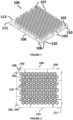
- FIGS. 1 and 2 illustrate devices configured to support a plurality of medical containers or a plurality of components of a medical container therein.
- the device may be referred to in the art generally as a nest.
- the medical containers may be vials, syringes, such as pre-fillable or prefilled syringes, and the like.
- the medical containers are configured, after filling, to contain a medical fluid therein.
- the components of the medical container may be stoppers, syringe gaskets, and the like.
- the device comprises a plate 100 having an upper surface 102, a lower surface 104, and a sidewall 106 extending between the upper surface 102 and the lower surface 104.
- the sidewall 106 defines a perimeter of the plate 100.
- the sidewall 106 comprises four edges 113 connected by corners 111, which may be square or rounded.
- indentations 105 may be formed in edges 113 of the plate 100. Such indentations 105 are configured to be gripped by a person or a machine to facilitate insertion and removal the plate 100 from a tub 130.
- the plate 100 may comprise a plurality of projections 108 that respectively define some portion of the sidewall 106.
- the projections 108 are those portions of the plate 100 having the greatest lateral dimensions (e.g., a width or length).
- the plurality of projections 108 define a minority of the periphery of the plate 100, and a remainder of the periphery of the plate 100 is recessed relative to the portion of the sidewall 106 defined by the projections 108.
- the plate 100 When the plate 100 is disposed in the tub 130, a space is provided between the remainder of the sidewall 106 and the interior surface 136 of the tub 130.
- the plate 100 may lack projections such that each edge of the plate 100 is substantially planar.
- a longitudinal axis of the plate 100 extends perpendicular to (e.g., normal to) the upper surface 102. Apart from features such as chimneys 107, the upper surface 102 of the plate 100 is substantially planar. The lower surface 104 may also be substantially planar.
- the plate 100 defines a plurality of openings 110 extending therethrough from the upper surface 102 to the lower surface 104.
- Each opening 110 is configured to retain a medical container or component of a medical container therein.
- the plate 100 may also comprise a plurality of chimneys 105 that protrude axially from the upper surface 102. Each chimney 105 extends at least partially circumferentially about a corresponding opening 110. Each chimney 105 may be a generally cylindrical structure. Each chimney 105 defines an opening within which a medical container may be retained. Each chimney 105 may have a centrally extending longitudinal axis that is parallel with the longitudinal axis of the plate 100. Each chimney 105 may be integrally formed with the plate 100.
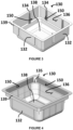
- FIGS. 3 and 4 illustrate exemplary embodiments of tubs 130 in which one or more plates 100 may be received.
- the tub 130 having one or more plates 100 disposed therein collectively form a packaging system 200 for receiving and transporting a plurality of medical containers or components of medical containers.
- the tub 130 comprises a plurality of sidewalls 132.
- the sidewalls 132 may extend from a bottom wall 138 that defines a base of the tub 130.
- the interior of the tub 130 is hollow and is defined by an interior surface of the bottom wall 138 and an interior surface 136 of the sidewalls 132.
- the tub 130 is open such that the plates 100 may be inserted therein.
- a flange 139 may be provided at an end of the sidewalls 132 opposite to which the bottom wall 138 is located.
- a sealing element may be coupled to a surface of the flange 139 to close the opening of the tub 130 and allow for sterilization of the packaging system 200.
- the tub 130 may comprise a plurality of projections 134 that respectively define a portion of the interior surface 136 of the tub 130.
- the plurality of projections 134 define a minimum lateral dimension (e.g., width or length) measured between opposing sidewalls 132. A remainder of the interior surface 136 defined by the sidewalls 132 is recessed relative to the interior surface 136 defined by the projections 134.
- the projections 108 of the plate 100 and the projections 134 of the tub 130 are respectively located such that when the plate 100 is disposed in the tub 130, the projections 108, 134 are collocated.
- the plate 100 and the tub 130 are designed such that, absent some material therebetween, the projections 108 of the plate 100 and the projections 134 of the tub 130 are in direct contact while a remainder of the sidewall 106 of the plate 100 and a remainder of the interior surface 136 of the tub 130 are separated from each other. This contact between the tub 130 and the plate 100 and rubbing therebetween may result in the production of particles as previously described herein.
- the tub 130 lacks projections 134.
- the sidewalls 132 may be stepped to define a ledge 135.
- the ledge 135 provides a horizontal surface configured to support the plate 100.
- the lower surface 104 of the plate 100 is disposed on the ledge 135.
- the ledge 135 may extend continuously or discontinuously along a perimeter of the interior surface 136.
- the plate 100 is disposed in the tub 130, absent some material therebetween, at least a portion of the sidewall 106 of the plate 100 contacts the interior surface 136 of the tub 130. This contact between the tub 130 and the plate 100 and rubbing therebetween may result in the production of particles as previously described herein.
- a material 150 having a composition different from a composition of each of the tub 130 and the plate 100 is disposed on the tub 130 and/or the plate 100 as described in further detail below.
- the tub 130 and/or the plate 100 may be formed of a plastic, such as a polyolefin including polyethylene or polypropylene, polystyrene, polycarbonate, polyester, or polyamide.
- the material 150 is located at an interface between the tub 130 and the plate 100 so as to prevent direct contact therebetween.
- FIGS. 1 and 2 illustrate embodiments in which the material 150 is disposed on the plate 100.
- the material 150 may be disposed on each of the projections 108 of the plate 100.
- the material 150 is disposed only on the projections 108 such that a remainder of the sidewall 106 is free of material.
- the material 150 may be provided along the sidewall 106 such that the entire perimeter of the plate 100 includes the material 150.
- FIGS. 3 and 4 illustrate embodiments in which the material 150 is disposed on the tub 130.
- the material 150 may be disposed on a portion of the interior surface 136 of the sidewalls 132 of the tub 130.
- the material 150 is disposed on the interior surface 136 of the tub 130 defined by the projections 134.
- the material 150 may be provided along a full height of the projection 134 between the flange 139 and the bottom wall 138. A remainder of the interior surface 136 of the tub 130 is free of the material 150.
- the material 150 is disposed on the interior surface 136 of the tub 130 defined by the portion of the sidewalls 132 located extending axially above the ledge 135.
- the material 150 may extend continuously or discontinuously along the respective sidewalls 132.
- the material 150 may be disposed on those surfaces of the sidewall 132 extending parallel to the edges 113 of the plate 100 when the plate 100 is disposed in the tub 130.
- the material may also extend on the ledge 135.
- the material 150 is disposed on each of the projections 134 of the tub 130. In some embodiments, the material 150 is disposed only to the projections such that a remainder of the interior surface of the tub 130 is free of material.
- the material 150 may be coupled to the plate 100 or the tub 130 by an adhesive or by bonding. Bonding may be accomplished by melt adhesion during a sequential injection molding process, also known as bi-injection process (e.g. overmolding or comolding). Alternatively, the material 150 may be provided separately and assembled to the tub 130 or to the plate 100.
- the material 150 coupled to the plate 100 or tub 130 by adhesive or bonding is selected to have a composition having a hardness less than a hardness of the composition of the tub 130 and the composition of the plate 100.
- the material 150 may have hardness on the Shore A Hardness Scale in a range from 20 to 75.
- the material 150 may comprise a thermoplastic elastomer, rubber or liquid silicone rubber.
- the Shore D Hardness of the plate 100 and/or tub 130 may be between 50 and 100.
- the material 150 may comprise an abrasion-resistant coating applied to portions of the interior surface 136 of the tub 130 or portions of the sidewall 106 of the plate 100.
- the abrasion-resistant coating may be a plastic coating.
- the material 150 may comprise one of polytetrafluoroethylene, polyether ether ketone, polyvinylidene fluoride, polyurethane, and polyoxymethylene.
- the abrasion resistance of the material 150 is sufficient such that the material is not abraded by the material of the tub 130 or plate 100.
- the material 150 may be applied to the tub 130 or plate 100 by painting, spraying, or dipping. Said application may be done locally (e.g. only applied to the portions of the tub and plate that contact each other), in particular by using a mask to cover the portions of the tub or plate on which it is not intended to apply the material.
- the material 150 is in a solid state. In other embodiments of the disclosure, the material 150 may be provided in a liquid state.
- the lubricant material may be silicone oil.
- the material 150 may be disposed between the plate 100 or tub 130 without being coupled to either the plate 100 or tub 130.
- the material 150 may be a sheet of material that is resistant to abrasion by the material of the plate 100 and tub 130.
- the material may be a sheet made of synthetic fibers.
- the sheet may be formed of a spunbonded, synthetic fiber, such as a sheet of TYVEK TM .
- the sheet is disposed within the interior space of the tub 130 prior to disposing the plate 100 within the tub 130.
- particles of the material of the plate 100 and the tub 130 are not created because contact between the tub 130 and the plate 100 is prevented during transportation.
Landscapes
- Health & Medical Sciences (AREA)
- Life Sciences & Earth Sciences (AREA)
- Veterinary Medicine (AREA)
- Animal Behavior & Ethology (AREA)
- Public Health (AREA)
- Biomedical Technology (AREA)
- Heart & Thoracic Surgery (AREA)
- General Health & Medical Sciences (AREA)
- Engineering & Computer Science (AREA)
- Vascular Medicine (AREA)
- Hematology (AREA)
- Anesthesiology (AREA)
- Surgery (AREA)
- Diabetes (AREA)
- Nuclear Medicine, Radiotherapy & Molecular Imaging (AREA)
- Medical Informatics (AREA)
- Molecular Biology (AREA)
- Packages (AREA)
Abstract
A packaging system for receiving medical containers or components of medical containers comprises a plate, a tub having a plurality of sidewalls defining an interior space in which the plate is received, and a material located between sidewalls of the plate and interior surfaces. The material is distinct from the plate and the tub and formed of a material having a composition different from each of a composition of the plate and a composition of the tub.
Description
- The present disclosure relates generally to a packaging system comprising a device for transporting medical containers, such as syringes, and/or components thereof, such as stoppers, and an associated container in which the device is received.
- Medical containers, such as pre-fillable or prefilled syringes, vials, and ampoules, and components for use with these containers, such as stoppers, may be transported from one site to another site. For instance, medical containers may be transported from a manufacturing site to a site at which the medical containers may be filled with a medicinal fluid. By way of further example, the medical containers may be manufactured and filled at the same site and subsequently transported to a storage site in a sterile packaging. During transportation, the medical containers may be supported by a holding device, which may be referred to as a nest. One or more holding devices may be disposed within a packaging having an opening allowing for placement of the holding devices therein and subsequently sealed by a sealing cover. The container may be referred to as a tub.
- External dimensions of the holding devices being slightly smaller than inner dimension of the packaging for ease of the assembly, the holding device may be susceptible to moving relative to the packaging during transportation. As a result of such movement during long-distance transport, the holding device rubs against an inner surface of the packaging and may wear away material of the packaging or of the holding device so as to create particles of the packaging material and/or the holding device material. Because the packaging is sealed by the sealing cover, the particles remain inside the packaging throughout the remainder of transportation and storage. Such particles may be dispersed within the packaging and thus disposed within or on the medical containers stored inside the packaging. When the medical containers arrive at the destination, the medical containers are intended to be in a ready-to-use condition. By way of non-limiting example, when the medical containers are pre-fillable syringes, the syringes are intended to be in a clean and sterile condition upon arrival at the filling site so that the syringes may be filled with medicinal fluid. If the particles of the packaging material and/or of the holding device material are dispersed within or on the syringes, the syringes are not in a ready-to-use condition and must be cleaned prior to filling in order to avoid contamination of the medicinal fluid with which the medical containers will be filled. Accordingly, there is a need for a packaging solution that would inhibit or altogether prevent the creation of particles within the packaging.
- An objective of the present disclosure is to provide a packaging system for receiving a plurality of medical containers or components of medical containers solving the above-mentioned drawbacks. The packaging system comprises:
- a plate having an upper surface, a lower surface, and a sidewall extending between the upper surface and the lower surface, the plate defining a plurality of openings extending therethrough from the upper surface to the lower surface, each opening configured to retain a medical container or component of a medical container therein, the plate comprising a plurality of projections that each define a portion of the sidewall;
- a tub having a plurality of sidewalls defining an interior space configured to receive the plate therein, the tub comprising a plurality of projections that each define a portion of an interior surface of the tub; and
- a material located between the portion of the sidewall of the plate defined by the projections and the portion of the interior surface of the tub defined by the plurality of projections, the material being distinct from the plate and the tub and formed of a material having a composition different from each of a composition of the plate and a composition of the tub.
- Certain preferred but non-limiting features of the packaging system described above are the following, taken individually or in combination:
- the material is coupled to the portion of the interior surface of the tub defined by the plurality of projections or to the portion of the sidewall of the plate defined by the projections;
- the composition of the material has hardness less than a hardness of each of the composition of the tub and the composition of the plate;
- the material comprises a thermoplastic elastomer, rubber or liquid silicone rubber;
- the material comprises a coating applied to the portion of the interior surface of the tub defined by the plurality of projections or to the portion of the sidewall of the plate defined by the plurality of projections;
- the material of the coating comprises one of polytetrafluoroethylene, polyether ether ketone, polyvinylidene fluoride, polyurethane, and polyoxymethylene;
- the material is a lubricant material, preferably silicone oil, applied to the portion of the interior surface of the tub defined by the plurality of projections and/or to the portion of the sidewall of the plate defined by the projections;
- the plurality of projections define a minority of a periphery of the plate, a remainder of the periphery of the plate is recessed relative to the portion of the sidewall defined by the projections such that, when the plate is disposed in the tub, a space is provided between the remainder of the sidewall and the interior surface of the tub, and the remainder of the sidewall is free of the material;
- the material is a sheet made of synthetic fibers and the material extends about a periphery of the plate.
- Another objective of the present disclosure is to provide a method of forming a packaging system for receiving a plurality of medical containers or components of medical containers, comprising disposing a material on one of:
- a portion of a sidewall of a plate that extends between an upper surface and a lower surface thereof and that is defined by a plurality of projections, and
- a portion of a sidewall of a tub that defines an interior space configured to receive the plate therein and that comprises a plurality of projections that each define a portion of an interior surface of the tub,
- Certain preferred but non-limiting features of the method described above are the following, taken individually or in combination:
- disposing the material comprises sequentially molding or bonding the material on one of the portion of the interior surface of the tub defined by the plurality of projections or to the portion of the sidewall of the plate defined by the plurality of projections;
- disposing the material comprises forming the material by dipping, painting, or spraying the material on one of the portion of the interior surface of the tub defined by the plurality of projections or to the portion of the sidewall (106) of the plate (100) defined by the plurality of projections (108).
- the material comprises a sheet formed of synthetic fibers, and disposing the material comprises disposing the sheet within the interior space of the tub prior to disposing the plate within the interior space of the tub;
- disposing the material comprises applying a layer of silicone oil to the portion of the interior surface of the tub defined by the plurality of projections and/or to the portion of the sidewall of the plate defined by the plurality of projections.
- The illustrations presented herein are not meant to be actual views of any particular component, device, or system, but are merely idealized representations which are employed to describe embodiments of the present invention. Other features, goals, and advantages of the present invention will appear more clearly upon reading of the detailed description that follows and with references to drawings provided by way of non-limiting examples wherein:
-
FIGS. 1 and 2 are views of a plate for a packaging system; -
FIGS. 3 and 4 are perspective views of a tub for a packaging system; and -
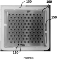
FIG. 5 is a top view of a packaging system including the tub and plate. - As used herein, relational terms, such as "first," "second," "top," "bottom," "upper," "lower," "over," "under," "on," "interior," "exterior," and the like, are used for clarity and convenience in understanding the disclosure and accompanying drawings and do not connote or depend on any specific preference, orientation, or order, except where the context clearly indicates otherwise.
- As used herein, the terms "axial," "axially," "longitudinal," and "longitudinally" generally mean and refer to a direction along or parallel to a longitudinal axis of an element(s) of the plate and packaging described herein.
- As used herein, the terms "lateral" and "laterally" generally mean and refer to a direction perpendicular to the central, longitudinal axis of the element(s) of the plate and packaging described herein.
- As used herein, the term "and/or" includes any and all combinations of one or more of the associated listed items.
- As used herein, the term "configured" refers to a size, shape, material composition, material distribution, orientation, and arrangement of one or more of at least one structure and at least one apparatus facilitating operation of one or more of the structure and the apparatus in a pre-determined way.
-
FIGS. 1 and 2 illustrate devices configured to support a plurality of medical containers or a plurality of components of a medical container therein. The device may be referred to in the art generally as a nest. The medical containers may be vials, syringes, such as pre-fillable or prefilled syringes, and the like. The medical containers are configured, after filling, to contain a medical fluid therein. The components of the medical container may be stoppers, syringe gaskets, and the like. - The device comprises a
plate 100 having anupper surface 102, a lower surface 104, and asidewall 106 extending between theupper surface 102 and the lower surface 104. - The
sidewall 106 defines a perimeter of theplate 100. Generally, thesidewall 106 comprises fouredges 113 connected bycorners 111, which may be square or rounded. In some embodiments,indentations 105 may be formed inedges 113 of theplate 100.Such indentations 105 are configured to be gripped by a person or a machine to facilitate insertion and removal theplate 100 from atub 130. - The
plate 100 may comprise a plurality ofprojections 108 that respectively define some portion of thesidewall 106. Theprojections 108 are those portions of theplate 100 having the greatest lateral dimensions (e.g., a width or length). The plurality ofprojections 108 define a minority of the periphery of theplate 100, and a remainder of the periphery of theplate 100 is recessed relative to the portion of thesidewall 106 defined by theprojections 108. When theplate 100 is disposed in thetub 130, a space is provided between the remainder of thesidewall 106 and theinterior surface 136 of thetub 130. In other embodiments, theplate 100 may lack projections such that each edge of theplate 100 is substantially planar. - A longitudinal axis of the
plate 100 extends perpendicular to (e.g., normal to) theupper surface 102. Apart from features such aschimneys 107, theupper surface 102 of theplate 100 is substantially planar. The lower surface 104 may also be substantially planar. - With continued reference to
FIGS. 1 and 2 , theplate 100 defines a plurality ofopenings 110 extending therethrough from theupper surface 102 to the lower surface 104. Eachopening 110 is configured to retain a medical container or component of a medical container therein. - The
plate 100 may also comprise a plurality ofchimneys 105 that protrude axially from theupper surface 102. Eachchimney 105 extends at least partially circumferentially about acorresponding opening 110. Eachchimney 105 may be a generally cylindrical structure. Eachchimney 105 defines an opening within which a medical container may be retained. Eachchimney 105 may have a centrally extending longitudinal axis that is parallel with the longitudinal axis of theplate 100. Eachchimney 105 may be integrally formed with theplate 100. -
FIGS. 3 and 4 illustrate exemplary embodiments oftubs 130 in which one ormore plates 100 may be received. Thetub 130 having one ormore plates 100 disposed therein collectively form a packaging system 200 for receiving and transporting a plurality of medical containers or components of medical containers. - With continued reference to
FIGS. 3 and 4 , thetub 130 comprises a plurality ofsidewalls 132. Thesidewalls 132 may extend from abottom wall 138 that defines a base of thetub 130. The interior of thetub 130 is hollow and is defined by an interior surface of thebottom wall 138 and aninterior surface 136 of thesidewalls 132. - Opposite the
bottom wall 138, thetub 130 is open such that theplates 100 may be inserted therein. Aflange 139 may be provided at an end of thesidewalls 132 opposite to which thebottom wall 138 is located. After one ormore plates 100 having medical containers or medical container components therein are disposed in thetub 130, a sealing element may be coupled to a surface of theflange 139 to close the opening of thetub 130 and allow for sterilization of the packaging system 200. - As illustrated in
FIG. 3 , thetub 130 may comprise a plurality ofprojections 134 that respectively define a portion of theinterior surface 136 of thetub 130. The plurality ofprojections 134 define a minimum lateral dimension (e.g., width or length) measured between opposingsidewalls 132. A remainder of theinterior surface 136 defined by thesidewalls 132 is recessed relative to theinterior surface 136 defined by theprojections 134. - The
projections 108 of theplate 100 and theprojections 134 of thetub 130 are respectively located such that when theplate 100 is disposed in thetub 130, theprojections plate 100 and thetub 130 are designed such that, absent some material therebetween, theprojections 108 of theplate 100 and theprojections 134 of thetub 130 are in direct contact while a remainder of thesidewall 106 of theplate 100 and a remainder of theinterior surface 136 of thetub 130 are separated from each other. This contact between thetub 130 and theplate 100 and rubbing therebetween may result in the production of particles as previously described herein. - In other embodiments, the
tub 130 lacksprojections 134. As illustrated inFIG. 4 , thesidewalls 132 may be stepped to define aledge 135. Theledge 135 provides a horizontal surface configured to support theplate 100. When theplate 100 is disposed in thetub 130, the lower surface 104 of theplate 100 is disposed on theledge 135. Theledge 135 may extend continuously or discontinuously along a perimeter of theinterior surface 136. When theplate 100 is disposed in thetub 130, absent some material therebetween, at least a portion of thesidewall 106 of theplate 100 contacts theinterior surface 136 of thetub 130. This contact between thetub 130 and theplate 100 and rubbing therebetween may result in the production of particles as previously described herein. There is also the possibility of having a contact between theprojections 108 of the plate and the sidewalls of the tub, even if said sidewalls do not have projections. - A
material 150 having a composition different from a composition of each of thetub 130 and theplate 100 is disposed on thetub 130 and/or theplate 100 as described in further detail below. Thetub 130 and/or theplate 100 may be formed of a plastic, such as a polyolefin including polyethylene or polypropylene, polystyrene, polycarbonate, polyester, or polyamide. - The
material 150 is located at an interface between thetub 130 and theplate 100 so as to prevent direct contact therebetween. -
FIGS. 1 and 2 illustrate embodiments in which thematerial 150 is disposed on theplate 100. In particular, thematerial 150 may be disposed on each of theprojections 108 of theplate 100. In some embodiments, thematerial 150 is disposed only on theprojections 108 such that a remainder of thesidewall 106 is free of material. In other embodiments, thematerial 150 may be provided along thesidewall 106 such that the entire perimeter of theplate 100 includes thematerial 150. -
FIGS. 3 and 4 illustrate embodiments in which thematerial 150 is disposed on thetub 130. In particular, thematerial 150 may be disposed on a portion of theinterior surface 136 of thesidewalls 132 of thetub 130. - In the embodiment illustrated in
FIG. 3 , thematerial 150 is disposed on theinterior surface 136 of thetub 130 defined by theprojections 134. Thematerial 150 may be provided along a full height of theprojection 134 between theflange 139 and thebottom wall 138. A remainder of theinterior surface 136 of thetub 130 is free of thematerial 150. - In the embodiment illustrated in
FIG. 4 , thematerial 150 is disposed on theinterior surface 136 of thetub 130 defined by the portion of thesidewalls 132 located extending axially above theledge 135. Thematerial 150 may extend continuously or discontinuously along therespective sidewalls 132. For example, thematerial 150 may be disposed on those surfaces of thesidewall 132 extending parallel to theedges 113 of theplate 100 when theplate 100 is disposed in thetub 130. Although not illustrated inFIG. 4 , the material may also extend on theledge 135. - With reference to
FIG. 3 , thematerial 150 is disposed on each of theprojections 134 of thetub 130. In some embodiments, thematerial 150 is disposed only to the projections such that a remainder of the interior surface of thetub 130 is free of material. - In some embodiments, the
material 150 may be coupled to theplate 100 or thetub 130 by an adhesive or by bonding. Bonding may be accomplished by melt adhesion during a sequential injection molding process, also known as bi-injection process (e.g. overmolding or comolding). Alternatively, thematerial 150 may be provided separately and assembled to thetub 130 or to theplate 100. - The
material 150 coupled to theplate 100 ortub 130 by adhesive or bonding is selected to have a composition having a hardness less than a hardness of the composition of thetub 130 and the composition of theplate 100. Thematerial 150 may have hardness on the Shore A Hardness Scale in a range from 20 to 75. Thematerial 150 may comprise a thermoplastic elastomer, rubber or liquid silicone rubber. The Shore D Hardness of theplate 100 and/ortub 130 may be between 50 and 100. By virtue of the presence of the relativelysofter material 150 between theplate 100 and thetub 130, particles of the material of theplate 100, thetub 130, and thematerial 150 are not created when theplate 100 having the material 150 thereon rubs against theinterior surface 136 of thetub 130 or when theplate 100 rubs against theinterior surface 136 of thetub 130 having the material 150 thereon during transportation. - In further embodiments of the disclosure, the
material 150 may comprise an abrasion-resistant coating applied to portions of theinterior surface 136 of thetub 130 or portions of thesidewall 106 of theplate 100. - The abrasion-resistant coating may be a plastic coating. The
material 150 may comprise one of polytetrafluoroethylene, polyether ether ketone, polyvinylidene fluoride, polyurethane, and polyoxymethylene. The abrasion resistance of thematerial 150 is sufficient such that the material is not abraded by the material of thetub 130 orplate 100. By virtue of the presence of the abrasion-resistant material 150 located between theplate 100 and thetub 130, particles of the material of theplate 100, thetub 130, and thematerial 150 are not created when theplate 100 having the material 150 thereon rubs against theinterior surface 136 of the tub or when theplate 100 rubs against theinterior surface 136 of thetub 130 during transportation. - The
material 150 may be applied to thetub 130 orplate 100 by painting, spraying, or dipping. Said application may be done locally (e.g. only applied to the portions of the tub and plate that contact each other), in particular by using a mask to cover the portions of the tub or plate on which it is not intended to apply the material. - In the previously described embodiments, the
material 150 is in a solid state. In other embodiments of the disclosure, thematerial 150 may be provided in a liquid state. - The lubricant material may be silicone oil. By virtue of the presence of the lubricant material located between the
plate 100 and thetub 130, particles of the material of theplate 100 and thetub 130 are not created when theplate 100 having the material 150 thereon rubs against theinterior surface 136 of the tub or when thetub 130 having the material thereon rubs against theplate 100 during transportation. - In another embodiment, such as the embodiment illustrated in
FIG. 5 , thematerial 150 may be disposed between theplate 100 ortub 130 without being coupled to either theplate 100 ortub 130. In such embodiments, thematerial 150 may be a sheet of material that is resistant to abrasion by the material of theplate 100 andtub 130. In particular, the material may be a sheet made of synthetic fibers. For example, the sheet may be formed of a spunbonded, synthetic fiber, such as a sheet of TYVEK™. - The sheet is disposed within the interior space of the
tub 130 prior to disposing theplate 100 within thetub 130. By virtue of the presence of the sheet located between theplate 100 and thetub 130, particles of the material of theplate 100 and thetub 130 are not created because contact between thetub 130 and theplate 100 is prevented during transportation. - While the present disclosure has been described herein with respect to certain illustrated embodiments, those of ordinary skill in the art will recognize and appreciate that it is not so limited. Rather, many additions, deletions, and modifications to the illustrated embodiments may be made without departing from the scope of the disclosure, including legal equivalents thereof. In addition, features from one embodiment may be combined with features of another embodiment while still being encompassed within the scope of the invention as contemplated by the inventors.
Claims (14)
- A packaging system (200) for receiving medical containers or components of medical containers, comprising:a plate (100) having an upper surface (102), a lower surface (104), and a sidewall (106) extending between the upper surface (102) and the lower surface (104), the plate (100) defining a plurality of openings (110) extending therethrough from the upper surface (102) to the lower surface (104), each opening (110) configured to retain a medical container or component of a medical container therein, the plate (100) comprising a plurality of projections (108) that each define a portion of the sidewall (106);a tub (130) having a plurality of sidewalls (132) defining an interior space configured to receive the plate (100) therein, the tub (130) comprising a plurality of projections (134) that each define a portion of an interior surface (136) of the tub (130); anda material (150) located between the portion of the sidewall (106) of the plate (100) defined by the projections (108) and the portion of the interior surface (136) of the tub (130) defined by the plurality of projections (134), the material (150) being distinct from the plate (100) and the tub (130) and formed of a material having a composition different from each of a composition of the plate (100) and a composition of the tub (130).
- The packaging system of claim 1, wherein the material (150) is coupled to the portion of the sidewall (106) of the plate (100) defined by the projections (108) or to the portion of the interior surface (136) of the tub (130) defined by the plurality of projections (134).
- The packaging system of either claim 1 or 2, wherein the composition of the material (150) has hardness less than a hardness of each of the composition of the tub (130) and the composition of the plate (100).
- The packaging system of any of claims 1-3, wherein the material (150) comprises a thermoplastic elastomer, rubber or liquid silicone rubber.
- The packaging system of claim 1, wherein the material (150) comprises a coating applied to the portion of the interior surface (136) of the tub (130) defined by the plurality of projections (134) or to the portion of the sidewall (106) of the plate (100) defined by the plurality of projections (108).
- The packaging system of claim 4, wherein the material (150) of the coating comprises one of polytetrafluoroethylene, polyether ether ketone, polyvinylidene fluoride, polyurethane, and polyoxymethylene.
- The packaging system of claim 1, wherein the material (150) is a lubricant material, preferably silicone oil, applied to the portion of the interior surface (136) of the tub (130) defined by the plurality of projections (134) and/or to the portion of the sidewall (106) of the plate (100) defined by the projections (108).
- The packaging system of any of claims 1-7, wherein:the plurality of projections (108) define a minority of a periphery of the plate (100),a remainder of the periphery of the plate (100) is recessed relative to the portion of the sidewall (106) defined by the projections (108) such that, when the plate (100) is disposed in the tub (130), a space is provided between the remainder of the sidewall (106) and the interior surface (136) of the tub (130), andthe remainder of the sidewall (106) is free of the material (150).
- The packaging system of claim 1, wherein the material (150) is a sheet made of synthetic fibers and the material (150) extends about a periphery of the plate (100).
- A method of forming a packaging system for receiving a plurality of medical containers or components of medical containers, comprising
disposing a material (150) on one of:a portion of a sidewall (106) of a plate (100) that extends between an upper surface (102) and a lower surface (104) thereof and that is defined by a plurality of projections (108), anda portion of a sidewall (132) of a tub (130) that defines an interior space configured to receive the plate (100) therein and that comprises a plurality of projections (134) that each define a portion of an interior surface (136) of the tub (130),wherein the material (150) is formed from a material having a composition different from each of a composition of the plate (100) and a composition of the tub (130). - The method of claim 10, wherein disposing the material (150) comprises overmolding, co-molding, or bonding the material (150) on one of the portion of the interior surface (136) of the tub (130) defined by the plurality of projections (134) or to the portion of the sidewall (106) of the plate (100) defined by the plurality of projections (108).
- The method of claim 10, wherein disposing the material (150) comprises forming the material (150) by dipping, painting, or spraying the material (150) on one of the portion of the interior surface (136) of the tub (130) defined by the plurality of projections (134) or to the portion of the sidewall (106) of the plate (100) defined by the plurality of projections (108).
- The method of claim 10, wherein the material (150) comprises a sheet (160) formed of synthetic fibers, and wherein disposing the material (150) comprises disposing the sheet (160) within the interior space of the tub (130) prior to disposing the plate (100) within the interior space of the tub (130).
- The method of claim 10, wherein disposing the material (150) comprises applying a layer of silicone oil to the portion of the interior surface (136) of the tub (130) defined by the plurality of projections (134) and/or to the portion of the sidewall (106) of the plate (100) defined by the plurality of projections (108).
Priority Applications (3)
| Application Number | Priority Date | Filing Date | Title |
|---|---|---|---|
| EP23306428.6A EP4516335A1 (en) | 2023-08-29 | 2023-08-29 | Packaging system for transporting medical devices and method of forming such a packaging system |
| CN202480055190.9A CN121793998A (en) | 2023-08-29 | 2024-08-29 | Packaging system for transporting medical devices and method of forming the same |
| PCT/EP2024/074211 WO2025046026A1 (en) | 2023-08-29 | 2024-08-29 | Packaging system for transporting medical devices and method of forming such a packaging system |
Applications Claiming Priority (1)
| Application Number | Priority Date | Filing Date | Title |
|---|---|---|---|
| EP23306428.6A EP4516335A1 (en) | 2023-08-29 | 2023-08-29 | Packaging system for transporting medical devices and method of forming such a packaging system |
Publications (1)
| Publication Number | Publication Date |
|---|---|
| EP4516335A1 true EP4516335A1 (en) | 2025-03-05 |
Family
ID=88017831
Family Applications (1)
| Application Number | Title | Priority Date | Filing Date |
|---|---|---|---|
| EP23306428.6A Pending EP4516335A1 (en) | 2023-08-29 | 2023-08-29 | Packaging system for transporting medical devices and method of forming such a packaging system |
Country Status (3)
| Country | Link |
|---|---|
| EP (1) | EP4516335A1 (en) |
| CN (1) | CN121793998A (en) |
| WO (1) | WO2025046026A1 (en) |
Citations (5)
| Publication number | Priority date | Publication date | Assignee | Title |
|---|---|---|---|---|
| WO2012143533A1 (en) * | 2011-04-21 | 2012-10-26 | Becton Dickinson France | Packaging for medical containers |
| EP2659980A1 (en) * | 2012-05-03 | 2013-11-06 | Schott AG | Support structure for simultaneously holding a plurality of medical or pharmaceutical containers and transport or packaging container with the same |
| WO2019068688A1 (en) * | 2017-10-02 | 2019-04-11 | Becton Dickinson France | Packaging device configured to support medical containers and method for removing the medical containers from said packaging device |
| WO2022161992A1 (en) * | 2021-01-26 | 2022-08-04 | Becton Dickinson France | A nest for the packaging of plunger stoppers with stacking pins ensuring a reliable alignment of a pile of nests |
| EP4091648A1 (en) * | 2021-05-18 | 2022-11-23 | Gerresheimer Glas GmbH | Transport tray for packaging units |
-
2023
- 2023-08-29 EP EP23306428.6A patent/EP4516335A1/en active Pending
-
2024
- 2024-08-29 WO PCT/EP2024/074211 patent/WO2025046026A1/en active Pending
- 2024-08-29 CN CN202480055190.9A patent/CN121793998A/en active Pending
Patent Citations (5)
| Publication number | Priority date | Publication date | Assignee | Title |
|---|---|---|---|---|
| WO2012143533A1 (en) * | 2011-04-21 | 2012-10-26 | Becton Dickinson France | Packaging for medical containers |
| EP2659980A1 (en) * | 2012-05-03 | 2013-11-06 | Schott AG | Support structure for simultaneously holding a plurality of medical or pharmaceutical containers and transport or packaging container with the same |
| WO2019068688A1 (en) * | 2017-10-02 | 2019-04-11 | Becton Dickinson France | Packaging device configured to support medical containers and method for removing the medical containers from said packaging device |
| WO2022161992A1 (en) * | 2021-01-26 | 2022-08-04 | Becton Dickinson France | A nest for the packaging of plunger stoppers with stacking pins ensuring a reliable alignment of a pile of nests |
| EP4091648A1 (en) * | 2021-05-18 | 2022-11-23 | Gerresheimer Glas GmbH | Transport tray for packaging units |
Also Published As
| Publication number | Publication date |
|---|---|
| WO2025046026A1 (en) | 2025-03-06 |
| CN121793998A (en) | 2026-04-03 |
Similar Documents
| Publication | Publication Date | Title |
|---|---|---|
| US11498709B2 (en) | Method for closing cartridges, supporting structure for supporting cartridge closures and transport or packaging container | |
| US8939288B2 (en) | Packaging for cylindrical containers | |
| US20220071846A1 (en) | Container holding member and medical container set | |
| RU2579742C2 (en) | Package for containers | |
| EP3646950B1 (en) | Transport unit and packaging structure for transporting and storing a plurality of containers for substances for pharmaceutical, medical or cosmetic uses | |
| US20150114871A1 (en) | Vial storage and transportation assembly | |
| WO2018020505A1 (en) | Method for closing vials, supporting structure for vial stopper members and transport or packaging container | |
| WO2013034737A1 (en) | Tray and packaging for medical containers | |
| CN110099706A (en) | Holding structure for simultaneously holding multiple containers of substances for pharmaceutical, medical or cosmetic applications, transport structure and transport or packaging container comprising the same | |
| US11241361B2 (en) | Holding device for the flexible treatment of pharmaceutical packaging materials | |
| WO2023161340A1 (en) | Holding device for medical containers with plates of different elevations | |
| WO2025046026A1 (en) | Packaging system for transporting medical devices and method of forming such a packaging system | |
| KR101276598B1 (en) | Lidded container | |
| US20250144288A1 (en) | Device and System for Transporting Medical Devices | |
| WO2019189423A1 (en) | Syringe storage container and syringe packaging body | |
| KR102085031B1 (en) | Syringe type container and filling apparatus | |
| KR102205149B1 (en) | Syringe type container for filling | |
| WO2025080925A1 (en) | Medical container holding device with rigidity-enhancing raised plateau | |
| US20050017014A1 (en) | Container | |
| WO2025054117A1 (en) | Medical container nest with reduced warpage and residual stress | |
| CA3060529A1 (en) | Transport unit and packaging structure for transporting and storing a plurality of containers for substances for pharmaceutical, medical or cosmetic uses | |
| KR20200109824A (en) | Composition for making syringe type container for easily filling and the syringe type container theirfrom |
Legal Events
| Date | Code | Title | Description |
|---|---|---|---|
| PUAI | Public reference made under article 153(3) epc to a published international application that has entered the european phase |
Free format text: ORIGINAL CODE: 0009012 |
|
| STAA | Information on the status of an ep patent application or granted ep patent |
Free format text: STATUS: THE APPLICATION HAS BEEN PUBLISHED |
|
| AK | Designated contracting states |
Kind code of ref document: A1 Designated state(s): AL AT BE BG CH CY CZ DE DK EE ES FI FR GB GR HR HU IE IS IT LI LT LU LV MC ME MK MT NL NO PL PT RO RS SE SI SK SM TR |
|
| STAA | Information on the status of an ep patent application or granted ep patent |
Free format text: STATUS: REQUEST FOR EXAMINATION WAS MADE |
|
| 17P | Request for examination filed |
Effective date: 20250624 |