EP4516325A1 - Uv irradiation device - Google Patents
Uv irradiation device Download PDFInfo
- Publication number
- EP4516325A1 EP4516325A1 EP23885910.2A EP23885910A EP4516325A1 EP 4516325 A1 EP4516325 A1 EP 4516325A1 EP 23885910 A EP23885910 A EP 23885910A EP 4516325 A1 EP4516325 A1 EP 4516325A1
- Authority
- EP
- European Patent Office
- Prior art keywords
- reflective member
- irradiation device
- ultraviolet
- electrodes
- ultraviolet irradiation
- Prior art date
- Legal status (The legal status is an assumption and is not a legal conclusion. Google has not performed a legal analysis and makes no representation as to the accuracy of the status listed.)
- Pending
Links
Images




Classifications
-
- A—HUMAN NECESSITIES
- A61—MEDICAL OR VETERINARY SCIENCE; HYGIENE
- A61L—METHODS OR APPARATUS FOR STERILISING MATERIALS OR OBJECTS IN GENERAL; DISINFECTION, STERILISATION OR DEODORISATION OF AIR; CHEMICAL ASPECTS OF BANDAGES, DRESSINGS, ABSORBENT PADS OR SURGICAL ARTICLES; MATERIALS FOR BANDAGES, DRESSINGS, ABSORBENT PADS OR SURGICAL ARTICLES
- A61L2/00—Disinfection or sterilisation of materials or objects, in general; Accessories therefor
- A61L2/02—Disinfection or sterilisation of materials or objects, in general; Accessories therefor using physical processes
- A61L2/08—Radiation
- A61L2/10—Ultraviolet [UV] radiation
-
- H—ELECTRICITY
- H01—ELECTRIC ELEMENTS
- H01J—ELECTRIC DISCHARGE TUBES OR DISCHARGE LAMPS
- H01J61/00—Gas-discharge or vapour-discharge lamps
- H01J61/02—Details
- H01J61/025—Associated optical elements
-
- H—ELECTRICITY
- H01—ELECTRIC ELEMENTS
- H01J—ELECTRIC DISCHARGE TUBES OR DISCHARGE LAMPS
- H01J61/00—Gas-discharge or vapour-discharge lamps
- H01J61/02—Details
- H01J61/04—Electrodes; Screens; Shields
- H01J61/06—Main electrodes
- H01J61/073—Main electrodes for high-pressure discharge lamps
- H01J61/0735—Main electrodes for high-pressure discharge lamps characterised by the material of the electrode
-
- A—HUMAN NECESSITIES
- A61—MEDICAL OR VETERINARY SCIENCE; HYGIENE
- A61L—METHODS OR APPARATUS FOR STERILISING MATERIALS OR OBJECTS IN GENERAL; DISINFECTION, STERILISATION OR DEODORISATION OF AIR; CHEMICAL ASPECTS OF BANDAGES, DRESSINGS, ABSORBENT PADS OR SURGICAL ARTICLES; MATERIALS FOR BANDAGES, DRESSINGS, ABSORBENT PADS OR SURGICAL ARTICLES
- A61L2103/00—Materials or objects being the target of disinfection or sterilisation
- A61L2103/75—Room floors or walls
-
- A—HUMAN NECESSITIES
- A61—MEDICAL OR VETERINARY SCIENCE; HYGIENE
- A61L—METHODS OR APPARATUS FOR STERILISING MATERIALS OR OBJECTS IN GENERAL; DISINFECTION, STERILISATION OR DEODORISATION OF AIR; CHEMICAL ASPECTS OF BANDAGES, DRESSINGS, ABSORBENT PADS OR SURGICAL ARTICLES; MATERIALS FOR BANDAGES, DRESSINGS, ABSORBENT PADS OR SURGICAL ARTICLES
- A61L2202/00—Aspects relating to methods or apparatus for disinfecting or sterilising materials or objects
- A61L2202/10—Apparatus features
- A61L2202/11—Apparatus for generating biocidal substances, e.g. vaporisers, UV lamps
Definitions
- Pathogens such as bacteria and fungi are everywhere, including on doorknobs, telephones, television remote controls, public restrooms, countertops, sidewalks, and the air.
- the ultraviolet lamp can be suitably used with easy operation at the necessary time by using a lamp method. There is an advantage in that the installation cost and the maintenance cost for installing the ultraviolet lamp are low. In addition, the ultraviolet light generated by the ultraviolet lamp rarely changes and thus continuously has the same sterilizing power.
- the ultraviolet lamp generates ultraviolet (UV) light with various wavelengths based on a material provided inside the lamp.
- UV-A wavelength of 400 nm to 315 nm
- UV-B wavelength of 315 nm to 280 nm
- UV-C wavelength of 280 nm to 110 nm
- sterilization using the ultraviolet lamp is more efficient than sterilization using heat, chemicals, ozone, or radiation.
- Another object of the present disclosure is to provide an ultraviolet irradiation device that can improve an amount of light of an ultraviolet lamp in a space where a plurality of electrodes is not disposed.
- an ultraviolet irradiation device comprising a housing, a plurality of electrodes configured to extend in a first direction in the housing and be spaced apart in a second direction perpendicular to the first direction, a plurality of ultraviolet lamps configured to emit ultraviolet light with a wavelength of 190 nm or more and 225 nm or less, extend in the second direction on the plurality of electrodes, and be spaced apart in the first direction, and a reflective member disposed between the plurality of ultraviolet lamps and the plurality of electrodes.
- a thickness of the reflective member may be 70 ⁇ m or more and 130 ⁇ m or less.
- a width where each of the plurality of ultraviolet lamps is in contact with the reflective member may be 190 ° or more and 280 ° or less.
- Each of the plurality of electrodes may include a tapered surface in contact with each of the plurality of ultraviolet lamps.
- the reflective member may be disposed below an area where the tapered surfaces are in contact with the plurality of ultraviolet lamps, and may extend in the second direction.
- the reflective member may include a plurality of reflective members that extends in the second direction and is spaced apart from each other in the first direction. Based on being viewed from above, an area of each of the plurality of reflective members may be larger than an area of each of the plurality of ultraviolet lamps.
- the plurality of electrodes may be formed of an aluminum material, and the reflective member may be formed of a polytetrafluoroethylene (PTFE) material.
- PTFE polytetrafluoroethylene
- the present disclosure can improve contact between the reflective member and the plurality of electrodes.
- the ultraviolet irradiation device may further comprise an additional reflective member disposed on the housing in a space between the plurality of electrodes and configured to face the plurality of ultraviolet lamps.
- the present disclosure can improve an amount of light of the ultraviolet lamps in a space in which the plurality of electrodes is not disclosed.
- the ultraviolet irradiation device may further comprise an optical filter coupled to the housing and disposed on the plurality of ultraviolet lamps.
- an ultraviolet irradiation device comprising a housing, a plurality of electrodes spaced apart in a first direction in the housing and configured to extend in a second direction perpendicular to the first direction, a plurality of ultraviolet lamps configured to emit ultraviolet light with a wavelength of 190 nm or more and 225 nm or less, extend in the second direction between the plurality of electrodes, and be spaced apart in the first direction, and a reflective member disposed between the plurality of ultraviolet lamps and the plurality of electrodes.
- the present disclosure can improve an amount of light emitted upward from the ultraviolet lamps.
- the reflective member may be formed in a film shape and may cover entire upper surfaces of the plurality of electrodes.
- the present disclosure can improve an amount of light of the ultraviolet irradiation device without a separate process such as cutting or bonding.
- the plurality of electrodes may include a first electrode block formed of a first electrode and a second electrode block that is formed of a second electrode and is spaced apart from the first electrode block in the first direction.
- the reflective member may include a plurality of reflective members that is disposed between the first electrode block and the second electrode block and is spaced apart in the first direction.
- a thickness of the reflective member may be 70 ⁇ m or more and 130 ⁇ m or less.
- the present disclosure can provide an ultraviolet irradiation device that can improve an amount of light emitted upward from an ultraviolet lamp.
- the present disclosure can provide an ultraviolet irradiation device that can improve contact between a reflective member and a plurality of electrodes.
- FIG. 1 is a perspective view of an ultraviolet irradiation device according to an embodiment of the present disclosure.
- FIG. 2 is an exploded perspective view of an ultraviolet irradiation device according to an embodiment of the present disclosure.
- FIG. 3 is a cross-sectional view of an ultraviolet irradiation device according to an embodiment of the present.
- the ultraviolet irradiation device 100 may be interpreted to mean a device generating UV-C, but is not limited thereto.
- the ultraviolet irradiation device 100 may be carried portably or installed in a certain location.
- the ultraviolet irradiation device 100 may emit ultraviolet light with a wavelength that is harmless to the human body and has sterilizing power.
- the ultraviolet irradiation device 100 may be formed in a hexahedral shape as a whole.
- the housing 110 may include an upper housing 112 and a lower housing 114.
- a mounting space in which the electrodes 130 and 140 are mounted may be formed in the lower housing 114.
- the upper housing 112 may be coupled to the lower housing 114.
- the upper housing 112 may fix the ultraviolet lamp 150 and the optical filter 160 while being coupled to the lower housing 114.
- the electrodes 130 and 140 may extend in a first direction.
- the electrodes 130 and 140 may include a plurality of electrodes 130 and 140 that are spaced apart from each other in a second direction.
- the first direction may be interpreted to mean an up-down direction based on FIG. 4
- the second direction may be interpreted to mean a left-right direction based on FIG. 4 .
- the plurality of electrodes 130 and 140 may include a first electrode block 130 formed of a first electrode and a second electrode block 140 that is formed of a second electrode and is spaced apart from the first electrode block 130 in the second direction.
- the first electrode block 130 and the second electrode block 140 may be formed in a shape corresponding to each other.
- the electrodes 130 and 140 may include a tapered surface on which the ultraviolet lamp 150 is mounted.
- the ultraviolet lamp 150 may be in contact with the tapered surfaces of the electrodes 130 and 140.
- the ultraviolet lamp 150 may be disposed in the housing 110.
- the ultraviolet lamp 150 may be formed in a cylindrical shape.
- the ultraviolet lamp 150 may be formed in a tube shape.
- the ultraviolet lamp 150 may extend in the second direction.
- the ultraviolet lamp 150 may be disposed on the electrodes 130 and 140.
- the ultraviolet lamp 150 may be disposed on the tapered surfaces of the electrodes 130 and 140.
- An outer circumferential surface of the ultraviolet lamp 150 may be in contact with the tapered surfaces of the electrodes 130 and 140.
- a central area of the ultraviolet lamp 150 may be mounted on the tapered surfaces of the electrodes 130 and 140, and both ends of the ultraviolet lamp 150 may be fixed by the upper housing 112.
- the ultraviolet lamp 150 may include a plurality of ultraviolet lamps 150 spaced apart from each other in the first direction.
- the ultraviolet lamp 150 may generate UV-C with a wavelength of 110 nm or more and 180 nm or less. Specifically, the ultraviolet lamp 150 may emit ultraviolet light with a wavelength of 190 nm or more and 225 nm or less. More specifically, the ultraviolet lamp 150 may emit ultraviolet light with a wavelength of 222 nm.
- the ultraviolet lamp 150 may be an excimer lamp in which a light emitting gas including KrCL, KrBr, and ArF is sealed. As a result, the ultraviolet lamp 150 can eradicate DNA of bacteria or fungi, which is harmless to the human body.
- the reflective member 170 may be disposed in the housing 110.
- the reflective member 170 may be disposed between the ultraviolet lamp 150 and the plurality of electrodes 130 and 140.
- the reflective member 170 may be formed in a thin film shape.
- the reflective member 170 may upward reflect light emitted downward from the ultraviolet lamp 150. As a result, the reflective member 170 can improve an amount of light emitted upward from the ultraviolet lamp 150.
- the reflective member 170 may be formed in a film shape and may cover entire upper surfaces of the plurality of electrodes 130 and 140. When the reflective member 170 has a thin film shape and covers the upper surfaces of the electrodes 130 and 140 as illustrated in FIG. 2 , the reflective member 170 may be deformed into the same shape as the upper surfaces of the electrodes 130 and 140. As a result, the reflective member 170 can improve an amount of light of the ultraviolet irradiation device 100 without a separate process such as cutting or bonding.
- a separate adhesive may be provided between the film-shaped reflective member 170 and the plurality of electrodes 130 and 140. In this case, structural stability of the ultraviolet irradiation device 100 can be improved, but a reflectance of the reflective member 170 may be reduced.
- the reflective member 170 may be formed by spraying PTFE powder on the upper surfaces of the plurality of electrodes 130 and 140 and performing drying and heat treatment on it. In this case, the reflectance of the reflective member 170 may be reduced due to an increase in other additives.
- the reflective member 170 may include a first reflective member 174 disposed on the first electrode block 130 and a second reflective member 172 disposed on the second electrode block 140.
- each of the first reflective member 174 and the second reflective member 172 may be formed in a thin and flexible film shape.
- the first reflective member 174 When the first reflective member 174 is disposed on the first electrode block 130, the first reflective member 174 may be deformed into a shape corresponding to the upper surface of the first electrode block 130, and when the second reflective member 172 is disposed on the second electrode block 140, the second reflective member 172 may be deformed into a shape corresponding to the upper surface of the second electrode block 140.
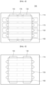
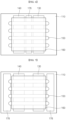
- FIGS. 4 to 8 are modifications of an ultraviolet irradiation device according to an embodiment of the present disclosure.
- FIG. 9 illustrates that a reflective member is removed from the ultraviolet irradiation device of FIG. 3 .
- FIG. 10 illustrates an amount of light of the ultraviolet irradiation device of FIGS. 4 to 8 .
- the reflective member 170 of the ultraviolet irradiation device 100 may include a plurality of reflective members 170 that extends in the second direction and is spaced apart from each other in the first direction.
- the area of each of the plurality of reflective members 170 may be larger than the area of each of the plurality of ultraviolet lamps 150.
- an ultraviolet irradiation device B may be configured to add the additional reflective member 176 to the ultraviolet irradiation device A of FIG. 5 .
- an ultraviolet irradiation device C may be configured to add both reflective members 178 to the ultraviolet irradiation device A of FIG. 5 .
- the both reflective members 178 may extend from both ends of the plurality of ultraviolet lamps 150 in the first direction.
- the both reflective members 178 may be disposed in the lower housing 114.
- an ultraviolet irradiation device D may be configured to add the additional reflective member 176 and both reflective members 178 to the ultraviolet irradiation device A of FIG. 5 .
- the reflective member 170 when the reflective member 170 is not disposed between the plurality of electrodes 130 and 140 and the plurality of ultraviolet lamps 150, light emitted downward from the plurality of ultraviolet lamps 150 is reflected upward from the plurality of electrodes 130 and 140. Hence, light leakage occurs. Therefore, as illustrated in FIG. 3 , the reflective member 170 that is in direct contact with the plurality of ultraviolet lamps 150 can reduce the leakage of light and improve an amount of light emitted upward from the ultraviolet irradiation device 100.
- the amount of light in the ultraviolet irradiation device 100 based on FIG. 4 is increased by about 30% compared to the amount of light in the ultraviolet irradiation device A based on FIG. 5 . It can also be seen that the amount of light in the ultraviolet irradiation device 100 based on FIG. 4 is increased compared to the amount of light in the ultraviolet irradiation devices B, C, and D based on FIGS. 6 to 8 . That is, when viewed from above, the area of each of the plurality of reflective members 170 may be larger than the area of each of the plurality of ultraviolet lamps 150, and the amount of light of the ultraviolet irradiation device 100 can be significantly improved as the additional reflective member 176 is provided.
- FIG. 11 illustrates an ultraviolet lamp and a reflective member of an ultraviolet irradiation device according to an embodiment of the present disclosure.
- FIG. 12 illustrates an amount of light depending on a thickness of a reflective member of an ultraviolet irradiation device according to an embodiment of the present disclosure.
- FIG. 13 illustrates an amount of light depending on a width of a reflective member of an ultraviolet irradiation device according to an embodiment of the present disclosure.
- the thickness t of the reflective member 170 may refer to a radial length of the ultraviolet lamp 150
- the width 'a' of the reflective member 170 may refer to a circumferential angle of the ultraviolet lamp 15.
- the thickness t of the reflective member 170 may be 70 ⁇ m or more and 130 ⁇ m or less. It can be seen that when the thickness t of the reflective member 170 is less than 70 ⁇ m or exceeds 130 ⁇ m, an increase rate of the amount of light is significantly reduced. Therefore, when the thickness t of the reflective member 170 is 70 ⁇ m or more and 130 ⁇ m or less, the amount of light of the ultraviolet irradiation device 100 can be maximized.
- the width 'a' where the ultraviolet lamp 150 is in contact with the reflective member 170 may be 190 ° or more and 280 ° or less. It can be seen that when the width 'a' of the reflective member 170 is less than 190 ° or exceeds 280 °, an increase rate of the amount of light is significantly reduced. Therefore, when the width 'a' of the reflective member 170 is 190 ° or more and 280 ° or less, the amount of light of the ultraviolet irradiation device 100 can be maximized.
- FIG. 14 is a perspective view of an ultraviolet irradiation device according to another embodiment of the present disclosure.
- FIG. 15 is an exploded perspective view of an ultraviolet irradiation device according to another embodiment of the present disclosure.
- an ultraviolet irradiation device 200 may include a housing 210, a plurality of electrodes 230 and 240, a plurality of ultraviolet lamps 250, an optical filter 260, and a reflective member 270, but may be implemented except for some of these components and may not exclude other additional components.
- the detailed configuration of the ultraviolet irradiation device 200 according to another embodiment of the present disclosure not described below can be understood to be the same as the detailed configuration of the ultraviolet irradiation device 100 according to an embodiment of the present disclosure.
- the plurality of electrodes 230 and 240 may be spaced apart from each other in a first direction.
- the plurality of electrodes 230 and 240 may extend in a second direction. That is, the extending direction of the plurality of electrodes 230 and 240 of the ultraviolet irradiation device 200 according to another embodiment of the present disclosure may be different from the extending direction of the plurality of electrodes 130 and 140 of the ultraviolet irradiation device 100 according to an embodiment of the present disclosure.
- the plurality of electrodes 230 and 240 may include first electrode blocks 230 extending in the second direction and second electrode blocks 240 that extend in the second direction and are spaced apart from the first electrode blocks 230 in the first direction.
- the plurality of electrodes 230 and 240 may be configured such that the first electrode blocks 230 and the second electrode blocks 240 are alternately arranged.
- the ultraviolet lamps 250 extending in the second direction may be disposed on tapered surfaces of the first electrode blocks 230 and the second electrode blocks 240.
- the ultraviolet lamp 250 may include the plurality of ultraviolet lamps 250 that extend in the second direction between the plurality of electrodes 230 and 240 and are spaced apart in the first direction.
- the reflective member 270 may be disposed between the plurality of ultraviolet lamps 250 and the plurality of electrodes 230 and 240. Through this, the reflective member 270 can improve an amount of light emitted upward from the ultraviolet lamps 250.
- the reflective member 270 may be formed in a film shape and may cover entire upper surfaces of the plurality of electrodes 230 and 240. Through this, the reflective member 270 can improve an amount of light of the ultraviolet irradiation device 200 without a separate process such as cutting or bonding.
- the reflective member 270 may include a plurality of reflective members 270 that are disposed between the first electrode block 230 and the second electrode block 240 and are spaced apart in the first direction.
- a thickness t of the reflective member 270 may be 70 ⁇ m or more and 130 ⁇ m or less. In the area where the reflective member 270 is in contact with the ultraviolet lamp 250, a width 'a' of the reflective member 270 may be 190 ° or more and 280 ° or less. As a result, the amount of light emitted upward from the ultraviolet lamp 250 can be improved.
- the plurality of electrodes 230 and 240 may be formed of an aluminum material, and the reflective member 270 may be formed of a PTFE material. As a result, the contact between the reflective member 270 and the plurality of electrodes 230 and 240 and the contact between the reflective member 270 and the ultraviolet lamp 250 can be improved.
Landscapes
- Health & Medical Sciences (AREA)
- Epidemiology (AREA)
- Life Sciences & Earth Sciences (AREA)
- Animal Behavior & Ethology (AREA)
- General Health & Medical Sciences (AREA)
- Public Health (AREA)
- Veterinary Medicine (AREA)
- Physical Or Chemical Processes And Apparatus (AREA)
Abstract
Description
- The present disclosure relates to an ultraviolet irradiation device. More specifically, the present disclosure relates to an ultraviolet irradiation device irradiating UV-C ultraviolet light.
- Pathogens such as bacteria and fungi are everywhere, including on doorknobs, telephones, television remote controls, public restrooms, countertops, sidewalks, and the air.
- In general, ultraviolet lamps are used in various fields to sterilize bacteria and fungi by generating ultraviolet light.
- The ultraviolet lamp can be suitably used with easy operation at the necessary time by using a lamp method. There is an advantage in that the installation cost and the maintenance cost for installing the ultraviolet lamp are low. In addition, the ultraviolet light generated by the ultraviolet lamp rarely changes and thus continuously has the same sterilizing power.
- The ultraviolet lamp generates ultraviolet (UV) light with various wavelengths based on a material provided inside the lamp. For example, UV-A (wavelength of 400 nm to 315 nm), UV-B (wavelength of 315 nm to 280 nm), UV-C (wavelength of 280 nm to 110 nm), and the like may be generated.
- Among them, ultraviolet light with a wavelength of 253.7 nm at the wavelength corresponding to UV-C has the best sterilizing power. When UV-C is irradiated to bacteria, fungi, etc., bacteria and fungi die because their DNA is damaged. That is, ultraviolet light has an effective sterilizing power against various bacteria by damaging DNA of living organisms.
- Therefore, sterilization using the ultraviolet lamp is more efficient than sterilization using heat, chemicals, ozone, or radiation.
- When ultraviolet light with a wavelength of 253.7 nm is irradiated to the human body, the ultraviolet light may adversely affect the human body.
- An object of the present disclosure is to provide an ultraviolet irradiation device that can improve an amount of light emitted upward from an ultraviolet lamp.
- Another object of the present disclosure is to provide an ultraviolet irradiation device that can improve an amount of light without a separate process such as cutting or bonding.
- Another object of the present disclosure is to provide an ultraviolet irradiation device that can improve contact between a reflective member and a plurality of electrodes.
- Another object of the present disclosure is to provide an ultraviolet irradiation device that can improve an amount of light of an ultraviolet lamp in a space where a plurality of electrodes is not disposed.
- In order to achieve the above-described objects, in one aspect of the present disclosure, there is provided an ultraviolet irradiation device comprising a housing, a plurality of electrodes configured to extend in a first direction in the housing and be spaced apart in a second direction perpendicular to the first direction, a plurality of ultraviolet lamps configured to emit ultraviolet light with a wavelength of 190 nm or more and 225 nm or less, extend in the second direction on the plurality of electrodes, and be spaced apart in the first direction, and a reflective member disposed between the plurality of ultraviolet lamps and the plurality of electrodes.
- Through this, the present disclosure can improve an amount of light emitted upward from the ultraviolet lamps.
- The reflective member may be formed in a film shape and may cover entire upper surfaces of the plurality of electrodes.
- Through this, the present disclosure can improve an amount of light of the ultraviolet irradiation device without a separate process such as cutting or bonding.
- The plurality of electrodes may include a first electrode block formed of a first electrode and a second electrode block that is formed of a second electrode and is spaced apart from the first electrode block in the second direction. The reflective member may include a first reflective member disposed on the first electrode block and a second reflective member disposed on the second electrode block.
- A thickness of the reflective member may be 70 µm or more and 130 µm or less.
- A width where each of the plurality of ultraviolet lamps is in contact with the reflective member may be 190 ° or more and 280 ° or less.
- Through this, the present disclosure can improve the amount of light emitted upward from the ultraviolet lamps.
- Each of the plurality of electrodes may include a tapered surface in contact with each of the plurality of ultraviolet lamps. The reflective member may be disposed below an area where the tapered surfaces are in contact with the plurality of ultraviolet lamps, and may extend in the second direction.
- The reflective member may include a plurality of reflective members that extends in the second direction and is spaced apart from each other in the first direction. Based on being viewed from above, an area of each of the plurality of reflective members may be larger than an area of each of the plurality of ultraviolet lamps.
- The plurality of electrodes may be formed of an aluminum material, and the reflective member may be formed of a polytetrafluoroethylene (PTFE) material.
- Through this, the present disclosure can improve contact between the reflective member and the plurality of electrodes.
- The ultraviolet irradiation device may further comprise an additional reflective member disposed on the housing in a space between the plurality of electrodes and configured to face the plurality of ultraviolet lamps.
- Through this, the present disclosure can improve an amount of light of the ultraviolet lamps in a space in which the plurality of electrodes is not disclosed.
- The ultraviolet irradiation device may further comprise an optical filter coupled to the housing and disposed on the plurality of ultraviolet lamps.
- In order to achieve the above-described objects, in one aspect of the present disclosure, there is provided an ultraviolet irradiation device comprising a housing, a plurality of electrodes spaced apart in a first direction in the housing and configured to extend in a second direction perpendicular to the first direction, a plurality of ultraviolet lamps configured to emit ultraviolet light with a wavelength of 190 nm or more and 225 nm or less, extend in the second direction between the plurality of electrodes, and be spaced apart in the first direction, and a reflective member disposed between the plurality of ultraviolet lamps and the plurality of electrodes.
- Through this, the present disclosure can improve an amount of light emitted upward from the ultraviolet lamps.
- The reflective member may be formed in a film shape and may cover entire upper surfaces of the plurality of electrodes.
- Through this, the present disclosure can improve an amount of light of the ultraviolet irradiation device without a separate process such as cutting or bonding.
- The plurality of electrodes may include a first electrode block formed of a first electrode and a second electrode block that is formed of a second electrode and is spaced apart from the first electrode block in the first direction. The reflective member may include a plurality of reflective members that is disposed between the first electrode block and the second electrode block and is spaced apart in the first direction.
- A thickness of the reflective member may be 70 µm or more and 130 µm or less.
- A width where each of the plurality of ultraviolet lamps is in contact with the reflective member may be 190 ° or more and 280 ° or less.
- Through this, the present disclosure can improve an amount of light emitted upward from the ultraviolet lamps.
- The plurality of electrodes may be formed of an aluminum material, and the reflective member may be formed of a polytetrafluoroethylene (PTFE) material.
- Through this, the present disclosure can improve contact between the reflective member and the plurality of electrodes.
- The reflective member may include a plurality of reflective members that extends in the second direction and is spaced apart from each other in the first direction. Based on being viewed from above, an area of each of the plurality of reflective members may be larger than an area of each of the plurality of ultraviolet lamps.
- The present disclosure can provide an ultraviolet irradiation device that can improve an amount of light emitted upward from an ultraviolet lamp.
- The present disclosure can provide an ultraviolet irradiation device that can improve an amount of light without a separate process such as cutting or bonding.
- The present disclosure can provide an ultraviolet irradiation device that can improve contact between a reflective member and a plurality of electrodes.
- The present disclosure can provide an ultraviolet irradiation device that can improve an amount of light of an ultraviolet lamp in a space where a plurality of electrodes is not disposed.
-
-
FIG. 1 is a perspective view of an ultraviolet irradiation device according to an embodiment of the present disclosure. -
FIG. 2 is an exploded perspective view of an ultraviolet irradiation device according to an embodiment of the present disclosure. -
FIG. 3 is a cross-sectional view of an ultraviolet irradiation device according to an embodiment of the present disclosure. -
FIGS. 4 to 8 are modifications of an ultraviolet irradiation device according to an embodiment of the present disclosure. -
FIG. 9 illustrates that a reflective member is removed from the ultraviolet irradiation device ofFIG. 3 . -
FIG. 10 illustrates an amount of light of the ultraviolet irradiation device ofFIGS. 4 to 8 . -
FIG. 11 illustrates an ultraviolet lamp and a reflective member of an ultraviolet irradiation device according to an embodiment of the present disclosure. -
FIG. 12 illustrates an amount of light depending on a thickness of a reflective member of an ultraviolet irradiation device according to an embodiment of the present disclosure. -
FIG. 13 illustrates an amount of light depending on a width of a reflective member of an ultraviolet irradiation device according to an embodiment of the present disclosure. -
FIG. 14 is a perspective view of an ultraviolet irradiation device according to another embodiment of the present disclosure. -
FIG. 15 is an exploded perspective view of an ultraviolet irradiation device according to another embodiment of the present disclosure. - Reference will now be made in detail to embodiments of the present disclosure, examples of which are illustrated in the accompanying drawings. Wherever possible, the same reference numbers will be used throughout the drawings to refer to the same or like parts.
- It should be understood that when a component is described as being "connected to" or "coupled to" other component, the component may be directly connected or coupled to the other component or intervening component(s) may be present.
- It will be noted that a detailed description of known arts will be omitted if it is determined that the detailed description of the known arts can obscure embodiments of the present disclosure. The accompanying drawings are used to help easily understand various technical features and it should be understood that embodiments presented herein are not limited by the accompanying drawings. As such, the present disclosure should be understood to extend to any alterations, equivalents and substitutes in addition to those which are particularly set out in the accompanying drawings.
- In addition, a term of "disclosure" may be replaced by terms such as document, specification, description, etc.
-
FIG. 1 is a perspective view of an ultraviolet irradiation device according to an embodiment of the present disclosure.FIG. 2 is an exploded perspective view of an ultraviolet irradiation device according to an embodiment of the present disclosure.FIG. 3 is a cross-sectional view of an ultraviolet irradiation device according to an embodiment of the present. - Referring to
FIGS. 1 to 3 , anultraviolet irradiation device 100 according to an embodiment of the present disclosure may include ahousing 110,electrodes ultraviolet lamp 150, anoptical filter 160, and areflective member 170, but may be implemented except for some of these components and may not exclude other additional components. - The
ultraviolet irradiation device 100 according to an embodiment of the present disclosure may be interpreted to mean a device generating UV-C, but is not limited thereto. Theultraviolet irradiation device 100 may be carried portably or installed in a certain location. Theultraviolet irradiation device 100 may emit ultraviolet light with a wavelength that is harmless to the human body and has sterilizing power. Theultraviolet irradiation device 100 may be formed in a hexahedral shape as a whole. - The
housing 110 may form an appearance of theultraviolet irradiation device 100. Thehousing 110 may be formed in a hexahedral shape as a whole. Theelectrodes ultraviolet lamp 150, theoptical filter 160, and thereflective member 170 may be disposed in thehousing 110. - The
housing 110 may include anupper housing 112 and alower housing 114. - A mounting space in which the
electrodes lower housing 114. Theupper housing 112 may be coupled to thelower housing 114. Theupper housing 112 may fix theultraviolet lamp 150 and theoptical filter 160 while being coupled to thelower housing 114. - The
electrodes electrodes electrodes - In an embodiment of the present disclosure, the first direction may be interpreted to mean an up-down direction based on
FIG. 4 , and the second direction may be interpreted to mean a left-right direction based onFIG. 4 . - The plurality of
electrodes first electrode block 130 formed of a first electrode and asecond electrode block 140 that is formed of a second electrode and is spaced apart from thefirst electrode block 130 in the second direction. Thefirst electrode block 130 and thesecond electrode block 140 may be formed in a shape corresponding to each other. - The
electrodes ultraviolet lamp 150 is mounted. Theultraviolet lamp 150 may be in contact with the tapered surfaces of theelectrodes - The
ultraviolet lamp 150 may be disposed in thehousing 110. Theultraviolet lamp 150 may be formed in a cylindrical shape. Theultraviolet lamp 150 may be formed in a tube shape. Theultraviolet lamp 150 may extend in the second direction. Theultraviolet lamp 150 may be disposed on theelectrodes ultraviolet lamp 150 may be disposed on the tapered surfaces of theelectrodes ultraviolet lamp 150 may be in contact with the tapered surfaces of theelectrodes ultraviolet lamp 150 may be mounted on the tapered surfaces of theelectrodes ultraviolet lamp 150 may be fixed by theupper housing 112. Theultraviolet lamp 150 may include a plurality ofultraviolet lamps 150 spaced apart from each other in the first direction. - The
ultraviolet lamp 150 may generate UV-C with a wavelength of 110 nm or more and 180 nm or less. Specifically, theultraviolet lamp 150 may emit ultraviolet light with a wavelength of 190 nm or more and 225 nm or less. More specifically, theultraviolet lamp 150 may emit ultraviolet light with a wavelength of 222 nm. Theultraviolet lamp 150 may be an excimer lamp in which a light emitting gas including KrCL, KrBr, and ArF is sealed. As a result, theultraviolet lamp 150 can eradicate DNA of bacteria or fungi, which is harmless to the human body. - The
optical filter 160 may be coupled to thehousing 110. Theoptical filter 160 may be disposed on theultraviolet lamp 150. Specifically, theoptical filter 160 may be mounted on thelower housing 114 and fixed by thelower housing 114. Theoptical filter 160 may not transmit ultraviolet light with a wavelength of 240 nm or more and 300 nm or less. Theoptical filter 160 may substantially transmit ultraviolet light with a wavelength of 190 nm or more and 225 nm or less. As a result, theoptical filter 160 can prevents ultraviolet light with wavelengths affecting the human body from being exposed to the outside. - The
reflective member 170 may be disposed in thehousing 110. Thereflective member 170 may be disposed between theultraviolet lamp 150 and the plurality ofelectrodes reflective member 170 may be formed in a thin film shape. Thereflective member 170 may upward reflect light emitted downward from theultraviolet lamp 150. As a result, thereflective member 170 can improve an amount of light emitted upward from theultraviolet lamp 150. - The
reflective member 170 may be formed of a flexible polytetrafluoroethylene (PTFE) material. Specifically, thereflective member 170 may be formed of a flexible material containing 90% or more of PTFE. When the plurality ofelectrodes electrodes ultraviolet lamp 150 may occur due to uneven distribution of an outer diameter or straightness of theultraviolet lamp 150. Since thereflective member 170 is formed of the PTFE material, the contact between the plurality ofelectrodes ultraviolet lamp 150 can be improved. - The
reflective member 170 may be formed in a film shape and may cover entire upper surfaces of the plurality ofelectrodes reflective member 170 has a thin film shape and covers the upper surfaces of theelectrodes FIG. 2 , thereflective member 170 may be deformed into the same shape as the upper surfaces of theelectrodes reflective member 170 can improve an amount of light of theultraviolet irradiation device 100 without a separate process such as cutting or bonding. - A separate adhesive may be provided between the film-shaped
reflective member 170 and the plurality ofelectrodes ultraviolet irradiation device 100 can be improved, but a reflectance of thereflective member 170 may be reduced. - Alternatively, the
reflective member 170 may be formed by spraying PTFE powder on the upper surfaces of the plurality ofelectrodes reflective member 170 may be reduced due to an increase in other additives. - The
reflective member 170 may include a firstreflective member 174 disposed on thefirst electrode block 130 and a secondreflective member 172 disposed on thesecond electrode block 140. In this case, each of the firstreflective member 174 and the secondreflective member 172 may be formed in a thin and flexible film shape. When the firstreflective member 174 is disposed on thefirst electrode block 130, the firstreflective member 174 may be deformed into a shape corresponding to the upper surface of thefirst electrode block 130, and when the secondreflective member 172 is disposed on thesecond electrode block 140, the secondreflective member 172 may be deformed into a shape corresponding to the upper surface of thesecond electrode block 140. -
FIGS. 4 to 8 are modifications of an ultraviolet irradiation device according to an embodiment of the present disclosure.FIG. 9 illustrates that a reflective member is removed from the ultraviolet irradiation device ofFIG. 3 .FIG. 10 illustrates an amount of light of the ultraviolet irradiation device ofFIGS. 4 to 8 . - Referring to
FIG. 4 , thereflective member 170 of theultraviolet irradiation device 100 according to an embodiment of the present disclosure may include a plurality ofreflective members 170 that extends in the second direction and is spaced apart from each other in the first direction. When viewed from above, the area of each of the plurality ofreflective members 170 may be larger than the area of each of the plurality ofultraviolet lamps 150. Through this, since ultraviolet light directed downward from theultraviolet lamps 150 is reflected and directed upward, the amount of light directed upward from theultraviolet lamps 150 can be improved. - Further, the
ultraviolet irradiation device 100 may include an additionalreflective member 176 that is disposed on thehousing 110 in a space between the plurality ofelectrodes ultraviolet lamps 150. The additionalreflective member 176 may be disposed on thelower housing 114. The additionalreflective member 176 may be disposed between thefirst electrode block 130 and thesecond electrode block 140. The additionalreflective member 176 may extend in the first direction. As a result, the additionalreflective member 176 can improve the amount of light directed upward from theultraviolet lamps 150 in a space in which the plurality ofelectrodes - Referring to
FIG. 5 , an ultraviolet irradiation device A according to an embodiment of the present disclosure may not include thereflective member 170 and the additionalreflective member 176. - Referring to
FIG. 6 , an ultraviolet irradiation device B according to an embodiment of the present disclosure may be configured to add the additionalreflective member 176 to the ultraviolet irradiation device A ofFIG. 5 . - Referring to
FIG. 7 , an ultraviolet irradiation device C according to an embodiment of the present disclosure may be configured to add bothreflective members 178 to the ultraviolet irradiation device A ofFIG. 5 . The bothreflective members 178 may extend from both ends of the plurality ofultraviolet lamps 150 in the first direction. The bothreflective members 178 may be disposed in thelower housing 114. - Referring to
FIG. 8 , an ultraviolet irradiation device D according to an embodiment of the present disclosure may be configured to add the additionalreflective member 176 and bothreflective members 178 to the ultraviolet irradiation device A ofFIG. 5 . - Referring to
FIG. 9 , when thereflective member 170 is not disposed between the plurality ofelectrodes ultraviolet lamps 150, light emitted downward from the plurality ofultraviolet lamps 150 is reflected upward from the plurality ofelectrodes FIG. 3 , thereflective member 170 that is in direct contact with the plurality ofultraviolet lamps 150 can reduce the leakage of light and improve an amount of light emitted upward from theultraviolet irradiation device 100. - Referring to
FIG. 10 , it can be seen that the amount of light in theultraviolet irradiation device 100 based onFIG. 4 is increased by about 30% compared to the amount of light in the ultraviolet irradiation device A based onFIG. 5 . It can also be seen that the amount of light in theultraviolet irradiation device 100 based onFIG. 4 is increased compared to the amount of light in the ultraviolet irradiation devices B, C, and D based onFIGS. 6 to 8 . That is, when viewed from above, the area of each of the plurality ofreflective members 170 may be larger than the area of each of the plurality ofultraviolet lamps 150, and the amount of light of theultraviolet irradiation device 100 can be significantly improved as the additionalreflective member 176 is provided. - Alternatively, the plurality of
reflective members 170 may be disposed only below an area where the tapered surfaces of the plurality ofelectrodes ultraviolet lamps 150. In this case, since light leaked downward from the plurality ofultraviolet lamps 150 is reflected upward while improving the ease of manufacturing, the amount of light of theultraviolet irradiation device 100 can be improved. -
FIG. 11 illustrates an ultraviolet lamp and a reflective member of an ultraviolet irradiation device according to an embodiment of the present disclosure.FIG. 12 illustrates an amount of light depending on a thickness of a reflective member of an ultraviolet irradiation device according to an embodiment of the present disclosure.FIG. 13 illustrates an amount of light depending on a width of a reflective member of an ultraviolet irradiation device according to an embodiment of the present disclosure. - Referring to
FIG. 11 , a thickness t and a width 'a' of thereflective member 170 in contact with theultraviolet lamp 150 of theultraviolet irradiation device 100 are described. Here, the thickness t of thereflective member 170 may refer to a radial length of theultraviolet lamp 150, and the width 'a' of thereflective member 170 may refer to a circumferential angle of the ultraviolet lamp 15. - Referring to
FIG. 12 , the thickness t of thereflective member 170 may be 70 µm or more and 130 µm or less. It can be seen that when the thickness t of thereflective member 170 is less than 70 µm or exceeds 130 µm, an increase rate of the amount of light is significantly reduced. Therefore, when the thickness t of thereflective member 170 is 70 µm or more and 130 µm or less, the amount of light of theultraviolet irradiation device 100 can be maximized. - Referring to
FIG. 13 , the width 'a' where theultraviolet lamp 150 is in contact with thereflective member 170 may be 190 ° or more and 280 ° or less. It can be seen that when the width 'a' of thereflective member 170 is less than 190 ° or exceeds 280 °, an increase rate of the amount of light is significantly reduced. Therefore, when the width 'a' of thereflective member 170 is 190 ° or more and 280 ° or less, the amount of light of theultraviolet irradiation device 100 can be maximized. -
FIG. 14 is a perspective view of an ultraviolet irradiation device according to another embodiment of the present disclosure.FIG. 15 is an exploded perspective view of an ultraviolet irradiation device according to another embodiment of the present disclosure. - Referring to
FIGS. 14 and15 , anultraviolet irradiation device 200 according to another embodiment of the present disclosure may include a housing 210, a plurality ofelectrodes ultraviolet lamps 250, anoptical filter 260, and areflective member 270, but may be implemented except for some of these components and may not exclude other additional components. - The detailed configuration of the
ultraviolet irradiation device 200 according to another embodiment of the present disclosure not described below can be understood to be the same as the detailed configuration of theultraviolet irradiation device 100 according to an embodiment of the present disclosure. - The plurality of
electrodes electrodes electrodes ultraviolet irradiation device 200 according to another embodiment of the present disclosure may be different from the extending direction of the plurality ofelectrodes ultraviolet irradiation device 100 according to an embodiment of the present disclosure. - The plurality of
electrodes electrodes ultraviolet lamps 250 extending in the second direction may be disposed on tapered surfaces of the first electrode blocks 230 and the second electrode blocks 240. - The
ultraviolet lamp 250 may include the plurality ofultraviolet lamps 250 that extend in the second direction between the plurality ofelectrodes - The
reflective member 270 may be disposed between the plurality ofultraviolet lamps 250 and the plurality ofelectrodes reflective member 270 can improve an amount of light emitted upward from theultraviolet lamps 250. - The
reflective member 270 may be formed in a film shape and may cover entire upper surfaces of the plurality ofelectrodes reflective member 270 can improve an amount of light of theultraviolet irradiation device 200 without a separate process such as cutting or bonding. - The
reflective member 270 may include a plurality ofreflective members 270 that are disposed between thefirst electrode block 230 and thesecond electrode block 240 and are spaced apart in the first direction. - In an area where the
reflective member 270 is in contact with theultraviolet lamp 250, a thickness t of thereflective member 270 may be 70 µm or more and 130 µm or less. In the area where thereflective member 270 is in contact with theultraviolet lamp 250, a width 'a' of thereflective member 270 may be 190 ° or more and 280 ° or less. As a result, the amount of light emitted upward from theultraviolet lamp 250 can be improved. - The plurality of
electrodes reflective member 270 may be formed of a PTFE material. As a result, the contact between thereflective member 270 and the plurality ofelectrodes reflective member 270 and theultraviolet lamp 250 can be improved. - The
reflective member 270 may include a plurality ofreflective members 270 that extend in the second direction and are spaced apart in the first direction. In this case, when viewed from above, an area of each of the plurality ofreflective members 270 may be larger than an area of each of the plurality ofultraviolet lamps 250. Through this, the amount of light directed upward from theultraviolet irradiation device 200 can be improved. - Some embodiments or other embodiments of the present disclosure described above are not exclusive or distinct from each other. Some embodiments or other embodiments of the present disclosure described above can be used together or combined in configuration or function.
- For example, configuration "A" described in an embodiment and/or the drawings and configuration "B" described in another embodiment and/or the drawings can be combined with each other. That is, even if the combination between the configurations is not directly described, the combination is possible except in cases where it is described that it is impossible to combine.
- The above detailed description is merely an example and is not to be considered as limiting the present disclosure. The scope of the present disclosure should be determined by rational interpretation of the appended claims, and all variations within the equivalent scope of the present disclosure are included in the scope of the present disclosure.
Claims (17)
- An ultraviolet irradiation device comprising:a housing;a plurality of electrodes configured to extend in a first direction in the housing and be spaced apart in a second direction perpendicular to the first direction;a plurality of ultraviolet lamps configured to emit ultraviolet light with a wavelength of 190 nm or more and 225 nm or less, extend in the second direction on the plurality of electrodes, and be spaced apart in the first direction; anda reflective member disposed between the plurality of ultraviolet lamps and the plurality of electrodes.
- The ultraviolet irradiation device of claim 1, wherein the reflective member is formed in a film shape and covers entire upper surfaces of the plurality of electrodes.
- The ultraviolet irradiation device of claim 1, wherein the plurality of electrodes includes a first electrode block formed of a first electrode and a second electrode block that is formed of a second electrode and is spaced apart from the first electrode block in the second direction, and
wherein the reflective member includes a first reflective member disposed on the first electrode block and a second reflective member disposed on the second electrode block. - The ultraviolet irradiation device of claim 1, wherein a thickness of the reflective member is 70 µm or more and 130 µm or less.
- The ultraviolet irradiation device of claim 1, wherein a width where each of the plurality of ultraviolet lamps is in contact with the reflective member is 190 ° or more and 280 ° or less.
- The ultraviolet irradiation device of claim 1, wherein each of the plurality of electrodes includes a tapered surface in contact with each of the plurality of ultraviolet lamps, and
wherein the reflective member is disposed below an area where the tapered surfaces are in contact with the plurality of ultraviolet lamps, and extends in the second direction. - The ultraviolet irradiation device of claim 1, wherein the reflective member includes a plurality of reflective members that extends in the second direction and is spaced apart from each other in the first direction, and
wherein, based on being viewed from above, an area of each of the plurality of reflective members is larger than an area of each of the plurality of ultraviolet lamps. - The ultraviolet irradiation device of claim 1, wherein the plurality of electrodes is formed of an aluminum material, and
wherein the reflective member is formed of a polytetrafluoroethylene (PTFE) material. - The ultraviolet irradiation device of claim 1, further comprising:
an additional reflective member disposed on the housing in a space between the plurality of electrodes and configured to face the plurality of ultraviolet lamps. - The ultraviolet irradiation device of claim 1, further comprising:
an optical filter coupled to the housing and disposed on the plurality of ultraviolet lamps. - An ultraviolet irradiation device comprising:a housing;a plurality of electrodes spaced apart in a first direction in the housing and configured to extend in a second direction perpendicular to the first direction;a plurality of ultraviolet lamps configured to emit ultraviolet light with a wavelength of 190 nm or more and 225 nm or less, extend in the second direction between the plurality of electrodes, and be spaced apart in the first direction; anda reflective member disposed between the plurality of ultraviolet lamps and the plurality of electrodes.
- The ultraviolet irradiation device of claim 11, wherein the reflective member is formed in a film shape and covers entire upper surfaces of the plurality of electrodes.
- The ultraviolet irradiation device of claim 11, wherein the plurality of electrodes includes a first electrode block formed of a first electrode and a second electrode block that is formed of a second electrode and is spaced apart from the first electrode block in the first direction, and
wherein the reflective member includes a plurality of reflective members that is disposed between the first electrode block and the second electrode block and is spaced apart in the first direction. - The ultraviolet irradiation device of claim 11, wherein a thickness of the reflective member is 70 µm or more and 130 µm or less.
- The ultraviolet irradiation device of claim 11, wherein a width where each of the plurality of ultraviolet lamps is in contact with the reflective member is 190 ° or more and 280 ° or less.
- The ultraviolet irradiation device of claim 11, wherein the plurality of electrodes is formed of an aluminum material, and
wherein the reflective member is formed of a polytetrafluoroethylene (PTFE) material. - The ultraviolet irradiation device of claim 11, wherein the reflective member includes a plurality of reflective members that extends in the second direction and is spaced apart from each other in the first direction, and
wherein, based on being viewed from above, an area of each of the plurality of reflective members is larger than an area of each of the plurality of ultraviolet lamps.
Applications Claiming Priority (2)
| Application Number | Priority Date | Filing Date | Title |
|---|---|---|---|
| KR1020220143751A KR102784499B1 (en) | 2022-11-01 | 2022-11-01 | Uv irradiation device |
| PCT/KR2023/006510 WO2024096212A1 (en) | 2022-11-01 | 2023-05-12 | Uv irradiation device |
Publications (2)
| Publication Number | Publication Date |
|---|---|
| EP4516325A1 true EP4516325A1 (en) | 2025-03-05 |
| EP4516325A4 EP4516325A4 (en) | 2025-12-31 |
Family
ID=90930612
Family Applications (1)
| Application Number | Title | Priority Date | Filing Date |
|---|---|---|---|
| EP23885910.2A Pending EP4516325A4 (en) | 2022-11-01 | 2023-05-12 | Uv irradiation device |
Country Status (3)
| Country | Link |
|---|---|
| EP (1) | EP4516325A4 (en) |
| KR (1) | KR102784499B1 (en) |
| WO (1) | WO2024096212A1 (en) |
Family Cites Families (8)
| Publication number | Priority date | Publication date | Assignee | Title |
|---|---|---|---|---|
| JP2003036723A (en) * | 2001-07-19 | 2003-02-07 | Harison Toshiba Lighting Corp | Lighting equipment |
| US9808544B2 (en) * | 2005-08-31 | 2017-11-07 | Ultraviolet Sciences, Inc. | Ultraviolet light treatment chamber |
| KR101509616B1 (en) * | 2014-10-23 | 2015-04-07 | 김재훈 | Space Sterilizer Using UV rays |
| KR102477411B1 (en) | 2016-07-22 | 2022-12-15 | 엘지전자 주식회사 | Ultraviolet rays sterilization lamp and ultraviolet rays sterilization module and air conditioner comprising the same |
| KR101883220B1 (en) * | 2017-09-27 | 2018-07-30 | 주식회사 엠디엠 | Ultraviolet sterilization module for air purification that improves the reflectance of ultraviolet lamp to increase sterilizing power and Ultraviolet sterilizer for air purification including thereof |
| TWI841791B (en) * | 2019-10-07 | 2024-05-11 | 日商牛尾電機股份有限公司 | UV irradiation device |
| JP6947261B1 (en) * | 2020-09-01 | 2021-10-13 | ウシオ電機株式会社 | Ultraviolet irradiation device |
| WO2022186169A1 (en) * | 2021-03-03 | 2022-09-09 | ウシオ電機株式会社 | Disaster prevention system and uv light irradiation system |
-
2022
- 2022-11-01 KR KR1020220143751A patent/KR102784499B1/en active Active
-
2023
- 2023-05-12 EP EP23885910.2A patent/EP4516325A4/en active Pending
- 2023-05-12 WO PCT/KR2023/006510 patent/WO2024096212A1/en not_active Ceased
Also Published As
| Publication number | Publication date |
|---|---|
| KR102784499B1 (en) | 2025-03-21 |
| WO2024096212A1 (en) | 2024-05-10 |
| KR20240061892A (en) | 2024-05-08 |
| EP4516325A4 (en) | 2025-12-31 |
Similar Documents
| Publication | Publication Date | Title |
|---|---|---|
| US11806434B2 (en) | Ultraviolet light treatment chamber | |
| EP2517268B1 (en) | Uv led based lamp for compact uv curing lamp assemblies | |
| KR101918044B1 (en) | Sterilizing device for shoes | |
| CN113975644A (en) | Microorganism inactivation treatment device, cell activation treatment device, and microorganism inactivation treatment method | |
| US20090155136A1 (en) | Ultraviolet light treatment chamber | |
| WO2017135190A1 (en) | Sterilization device | |
| US11925720B2 (en) | Highly efficient UV C bulb with multifaceted filter | |
| WO2017159342A1 (en) | Ultraviolet radiation device | |
| JP2022082620A (en) | How to use the ultraviolet light irradiation device and the ultraviolet light irradiation device | |
| EP4516325A1 (en) | Uv irradiation device | |
| KR102585542B1 (en) | Light irradiation device | |
| CN101937829B (en) | Ultraviolet lamp and ultraviolet irradiation device | |
| EP4000644A1 (en) | Integrated uv disinfection | |
| EP4245360A1 (en) | Ultraviolet light irradiation device | |
| EP4325546A1 (en) | Ultraviolet light irradiation device | |
| JP2023149743A (en) | Ultraviolet light irradiation device | |
| KR102824628B1 (en) | Uv irradiation device | |
| KR100714457B1 (en) | Light extractor induces light scattering | |
| KR20220164955A (en) | Eximer lamp and case, and light irradiation device having the same | |
| RU2746562C1 (en) | Air disinfection device | |
| US20260077085A1 (en) | Optical fluid processing apparatus | |
| US20240157011A1 (en) | Device for treatment with activated oxygen and method for treatment with activated oxygen | |
| WO2023175068A1 (en) | A disinfection lighting device | |
| KR20240030196A (en) | Light irradiation device for surface modification | |
| WO2024202314A1 (en) | Ultraviolet ray irradiation device |
Legal Events
| Date | Code | Title | Description |
|---|---|---|---|
| STAA | Information on the status of an ep patent application or granted ep patent |
Free format text: STATUS: THE INTERNATIONAL PUBLICATION HAS BEEN MADE |
|
| PUAI | Public reference made under article 153(3) epc to a published international application that has entered the european phase |
Free format text: ORIGINAL CODE: 0009012 |
|
| STAA | Information on the status of an ep patent application or granted ep patent |
Free format text: STATUS: REQUEST FOR EXAMINATION WAS MADE |
|
| 17P | Request for examination filed |
Effective date: 20241128 |
|
| AK | Designated contracting states |
Kind code of ref document: A1 Designated state(s): AL AT BE BG CH CY CZ DE DK EE ES FI FR GB GR HR HU IE IS IT LI LT LU LV MC ME MK MT NL NO PL PT RO RS SE SI SK SM TR |
|
| RIC1 | Information provided on ipc code assigned before grant |
Ipc: A61L 2/10 20060101AFI20250902BHEP Ipc: H01J 61/02 20060101ALI20250902BHEP Ipc: H01J 61/073 20060101ALI20250902BHEP |
|
| A4 | Supplementary search report drawn up and despatched |
Effective date: 20251201 |
|
| RIC1 | Information provided on ipc code assigned before grant |
Ipc: A61L 2/10 20060101AFI20251125BHEP Ipc: H01J 61/02 20060101ALI20251125BHEP Ipc: H01J 61/073 20060101ALI20251125BHEP |
|
| DAV | Request for validation of the european patent (deleted) | ||
| DAX | Request for extension of the european patent (deleted) |