EP4516255A1 - Surgery support system and surgery support system control method - Google Patents
Surgery support system and surgery support system control method Download PDFInfo
- Publication number
- EP4516255A1 EP4516255A1 EP23831381.1A EP23831381A EP4516255A1 EP 4516255 A1 EP4516255 A1 EP 4516255A1 EP 23831381 A EP23831381 A EP 23831381A EP 4516255 A1 EP4516255 A1 EP 4516255A1
- Authority
- EP
- European Patent Office
- Prior art keywords
- surgical instrument
- tilt
- endoscope
- display
- axis
- Prior art date
- Legal status (The legal status is an assumption and is not a legal conclusion. Google has not performed a legal analysis and makes no representation as to the accuracy of the status listed.)
- Pending
Links
Images





Classifications
-
- A—HUMAN NECESSITIES
- A61—MEDICAL OR VETERINARY SCIENCE; HYGIENE
- A61B—DIAGNOSIS; SURGERY; IDENTIFICATION
- A61B34/00—Computer-aided surgery; Manipulators or robots specially adapted for use in surgery
- A61B34/30—Surgical robots
-
- A—HUMAN NECESSITIES
- A61—MEDICAL OR VETERINARY SCIENCE; HYGIENE
- A61B—DIAGNOSIS; SURGERY; IDENTIFICATION
- A61B34/00—Computer-aided surgery; Manipulators or robots specially adapted for use in surgery
- A61B34/30—Surgical robots
- A61B34/37—Leader-follower robots
-
- A—HUMAN NECESSITIES
- A61—MEDICAL OR VETERINARY SCIENCE; HYGIENE
- A61B—DIAGNOSIS; SURGERY; IDENTIFICATION
- A61B34/00—Computer-aided surgery; Manipulators or robots specially adapted for use in surgery
- A61B34/70—Manipulators specially adapted for use in surgery
- A61B34/74—Manipulators with manual electric input means
-
- A—HUMAN NECESSITIES
- A61—MEDICAL OR VETERINARY SCIENCE; HYGIENE
- A61B—DIAGNOSIS; SURGERY; IDENTIFICATION
- A61B34/00—Computer-aided surgery; Manipulators or robots specially adapted for use in surgery
- A61B34/70—Manipulators specially adapted for use in surgery
- A61B34/77—Manipulators with motion or force scaling
-
- A—HUMAN NECESSITIES
- A61—MEDICAL OR VETERINARY SCIENCE; HYGIENE
- A61B—DIAGNOSIS; SURGERY; IDENTIFICATION
- A61B90/00—Instruments, implements or accessories specially adapted for surgery or diagnosis and not covered by any of the groups A61B1/00 - A61B50/00, e.g. for luxation treatment or for protecting wound edges
- A61B90/36—Image-producing devices or illumination devices not otherwise provided for
- A61B90/37—Surgical systems with images on a monitor during operation
-
- A—HUMAN NECESSITIES
- A61—MEDICAL OR VETERINARY SCIENCE; HYGIENE
- A61B—DIAGNOSIS; SURGERY; IDENTIFICATION
- A61B90/00—Instruments, implements or accessories specially adapted for surgery or diagnosis and not covered by any of the groups A61B1/00 - A61B50/00, e.g. for luxation treatment or for protecting wound edges
- A61B90/50—Supports for surgical instruments, e.g. articulated arms
-
- B—PERFORMING OPERATIONS; TRANSPORTING
- B25—HAND TOOLS; PORTABLE POWER-DRIVEN TOOLS; MANIPULATORS
- B25J—MANIPULATORS; CHAMBERS PROVIDED WITH MANIPULATION DEVICES
- B25J13/00—Controls for manipulators
-
- A—HUMAN NECESSITIES
- A61—MEDICAL OR VETERINARY SCIENCE; HYGIENE
- A61B—DIAGNOSIS; SURGERY; IDENTIFICATION
- A61B34/00—Computer-aided surgery; Manipulators or robots specially adapted for use in surgery
- A61B34/20—Surgical navigation systems; Devices for tracking or guiding surgical instruments, e.g. for frameless stereotaxis
- A61B2034/2046—Tracking techniques
- A61B2034/2048—Tracking techniques using an accelerometer or inertia sensor
-
- A—HUMAN NECESSITIES
- A61—MEDICAL OR VETERINARY SCIENCE; HYGIENE
- A61B—DIAGNOSIS; SURGERY; IDENTIFICATION
- A61B34/00—Computer-aided surgery; Manipulators or robots specially adapted for use in surgery
- A61B34/30—Surgical robots
- A61B2034/301—Surgical robots for introducing or steering flexible instruments inserted into the body, e.g. catheters or endoscopes
-
- A—HUMAN NECESSITIES
- A61—MEDICAL OR VETERINARY SCIENCE; HYGIENE
- A61B—DIAGNOSIS; SURGERY; IDENTIFICATION
- A61B90/00—Instruments, implements or accessories specially adapted for surgery or diagnosis and not covered by any of the groups A61B1/00 - A61B50/00, e.g. for luxation treatment or for protecting wound edges
- A61B90/06—Measuring instruments not otherwise provided for
- A61B2090/067—Measuring instruments not otherwise provided for for measuring angles
-
- A—HUMAN NECESSITIES
- A61—MEDICAL OR VETERINARY SCIENCE; HYGIENE
- A61B—DIAGNOSIS; SURGERY; IDENTIFICATION
- A61B90/00—Instruments, implements or accessories specially adapted for surgery or diagnosis and not covered by any of the groups A61B1/00 - A61B50/00, e.g. for luxation treatment or for protecting wound edges
- A61B90/36—Image-producing devices or illumination devices not otherwise provided for
- A61B90/37—Surgical systems with images on a monitor during operation
- A61B2090/372—Details of monitor hardware
-
- A—HUMAN NECESSITIES
- A61—MEDICAL OR VETERINARY SCIENCE; HYGIENE
- A61B—DIAGNOSIS; SURGERY; IDENTIFICATION
- A61B90/00—Instruments, implements or accessories specially adapted for surgery or diagnosis and not covered by any of the groups A61B1/00 - A61B50/00, e.g. for luxation treatment or for protecting wound edges
- A61B90/50—Supports for surgical instruments, e.g. articulated arms
- A61B2090/5025—Supports for surgical instruments, e.g. articulated arms with a counter-balancing mechanism
-
- A—HUMAN NECESSITIES
- A61—MEDICAL OR VETERINARY SCIENCE; HYGIENE
- A61B—DIAGNOSIS; SURGERY; IDENTIFICATION
- A61B90/00—Instruments, implements or accessories specially adapted for surgery or diagnosis and not covered by any of the groups A61B1/00 - A61B50/00, e.g. for luxation treatment or for protecting wound edges
- A61B90/50—Supports for surgical instruments, e.g. articulated arms
- A61B2090/508—Supports for surgical instruments, e.g. articulated arms with releasable brake mechanisms
Definitions
- the present disclosure relates to a robotic surgical system and a control method for a robotic surgical system.
- the robotic surgical system disclosed in U.S. Patent Application Publication No. 2012/0283876 includes a master controller and a slaved robotic manipulator.
- the master controller includes a display and an operation unit.
- a surgical instrument is attached to the slaved robotic manipulator.
- An image of a surgical site captured by an endoscope is displayed on the display of the master controller.
- the surgical instrument attached to the slaved robotic manipulator is moved by an operator operating the operation unit of the master controller while viewing the image of the surgical site displayed on the display.
- the display angle of the display of the master controller can be adjusted.
- Patent Document 1 U.S. Patent Application Publication No. 2012/0283876
- the inventors of the present disclosure have found that when the operator operates the operation unit to translationally move the surgical instrument along a desired direction, the direction in which the operator operates the operation unit changes before and after the display angle of the display is changed, even though the desired direction in which the operator wants to translationally move the surgical instrument does not change. Therefore, when the display angle of the display is changed, the surgical instrument cannot be accurately translationally moved in the desired direction intended by the operator.
- the present disclosure is intended to solve the above problem.
- the present disclosure aims to provide a robotic surgical system and a control method for a robotic surgical system each capable of accurately translationally moving a surgical instrument in a desired direction intended by an operator even when the tilt of a display changes.
- a robotic surgical system includes a surgical apparatus including a first robot arm having an endoscope attached to a distal end thereof, and a second robot arm having a predetermined surgical instrument other than the endoscope attached to a distal end thereof, an operation apparatus including an operation unit to receive an operation for the predetermined surgical instrument or the endoscope, and a control device configured or programmed to perform a control to move the predetermined surgical instrument or the endoscope based on a received operation.
- the operation apparatus includes a display to display an image captured by the endoscope and rotate so as to be tilted with respect to a horizontal plane, and a tilt detection sensor to detect a tilt of the display with respect to the horizontal plane.
- the control device is configured or programmed to correct translational movement of the predetermined surgical instrument based on the tilt detected by the tilt detection sensor.
- the control device is configured or programmed to correct the translational movement of the predetermined surgical instrument based on the tilt detected by the tilt detection sensor to detect the tilt of the display with respect to the horizontal plane. Accordingly, even when the tilt of the display with respect to the horizontal plane changes, the translational movement of the predetermined surgical instrument is corrected by the control device. Therefore, even when the tilt of the display changes, the surgical instrument can be accurately translationally moved in the desired direction intended by an operator. Furthermore, the tilt of the display with respect to the horizontal plane can be relatively easily detected by the tilt detection sensor. Therefore, even when the tilt of the display changes, the surgical instrument can be accurately translationally moved in the desired direction intended by the operator while the tilt of the display with respect to the horizontal plane is easily detected.
- a control method for a robotic surgical system is a control method for a robotic surgical system including a surgical apparatus including a first robot arm having an endoscope attached to a distal end thereof and a second robot arm having a predetermined surgical instrument other than the endoscope attached to a distal end thereof, an operation apparatus including an operation unit to receive an operation for the predetermined surgical instrument or the endoscope, and a control device configured or programmed to perform a control to move the predetermined surgical instrument or the endoscope based on a received operation, and the control method includes detecting a tilt with respect to a horizontal plane of a display operable to display an image captured by the endoscope, the display being operable to rotate so as to be tilted with respect to the horizontal plane, and correcting translational movement of the predetermined surgical instrument based on a detected tilt.
- the control method for the robotic surgical system includes detecting, using a tilt detection sensor, the tilt with respect to the horizontal plane of the display operable to display the image captured by the endoscope, the display being operable to rotate so as to be tilted with respect to the horizontal plane, and correcting the translational movement of the predetermined surgical instrument based on the detected tilt. Accordingly, even when the tilt of the display with respect to the horizontal plane changes, the translational movement of the predetermined surgical instrument is corrected. Therefore, it is possible to provide the control method for the robotic surgical system capable of accurately translationally moving the surgical instrument in the desired direction intended by an operator even when the tilt of the display changes.
- the tilt of the display with respect to the horizontal plane can be relatively easily detected by the tilt detection sensor. Therefore, it is possible to provide the control method for the robotic surgical system capable of accurately translationally moving the surgical instrument in the desired direction intended by the operator while easily detecting the tilt of the display with respect to the horizontal plane even when the tilt of the display changes.
- the surgical instrument can be accurately translationally moved in the desired direction intended by the operator even when the tilt of the display changes.
- the configuration of a robotic surgical system 100 includes a surgical robot 1 and a remote control apparatus 2.
- the surgical robot 1 and the remote control apparatus 2 are examples of a surgical apparatus and an operation apparatus, respectively.
- the longitudinal direction of a shaft 4c of a surgical instrument 4 is defined as a Z direction, as shown in FIG. 2 .
- the distal end side of the surgical instrument 4 is defined as a Z1 side
- the proximal end side of the surgical instrument 4 is defined as a Z2 side.
- a direction perpendicular to the Z direction is defined as an X direction.
- a direction perpendicular to the Z direction and the X direction is defined as a Y direction.
- a direction along a vertical direction is defined as a Za direction.
- a first side is defined as a Za1 side
- a second side is defined as a Za2 side.
- a direction perpendicular to the Z direction is defined as an Xa direction.
- a first side is defined as an Xa1 side
- a second side is defined as an Xa2 side.
- a direction perpendicular to the Za direction and the Xa direction is defined as a Ya direction.
- a first side is defined as a Ya1 side
- a second side is defined as a Ya2 side.
- the Xa direction and the Ya direction are directions along a horizontal plane.
- the surgical robot 1 is arranged in an operating room.
- the remote control apparatus 2 is spaced apart from the surgical robot 1.
- An operator such as a doctor inputs a command to the remote control apparatus 2 to cause the surgical robot 1 to perform a desired operation.
- the remote control apparatus 2 transmits the input command to the surgical robot 1.
- the surgical robot 1 operates based on the received command.
- the surgical robot 1 is arranged in the operating room that is a sterilized sterile field.
- the surgical robot 1 includes a medical cart 3, a positioner 40, an arm base 50, a plurality of robot arms 60, and arm operation units 80.
- the medical cart 3 moves the positioner 40.
- the medical cart 3 includes an input 33.
- the input 33 receives operations to move the positioner 40, the arm base 50, and the plurality of robot arms 60 or change their postures mainly in order to prepare for surgery before the surgery.
- the medical cart 3 includes an operation handle 34 to receive an operator's steering operation.
- the positioner 40 includes a 7-axis articulated robot, for example.
- the positioner 40 is arranged on the medical cart 3.
- the positioner 40 adjusts the position of the arm base 50.
- the positioner 40 moves the position of the arm base 50 three-dimensionally.
- the positioner 40 includes a base 41 and a plurality of links 42 coupled to the base 41.
- the plurality of links 42 are connected to each other by joints 43.
- the arm base 50 is attached to a distal end of the positioner 40.
- a proximal end of each of the plurality of robot arms 60 is attached to the arm base 50.
- Each of the plurality of robot arms 60 is able to take a folded and stored posture.
- the arm base 50 and the plurality of robot arms 60 are covered with sterile drapes and used.
- each of the robot arms 60 supports the surgical instrument 4.
- the plurality of robot arms 60 are arranged. Specifically, four robot arms 60a, 60b, 60c, and 60d are arranged.
- the robot arms 60a, 60b, 60c, and 60d have the same or similar configurations as each other.
- the robot arms 60a, 60b, and 60d are examples of a second robot arm, and the robot arm 60c is an example of a first robot arm.
- each robot arm 60 includes an arm portion 61, a first link 72, a second link 73, and a translation mechanism 70.
- the robot arm 60 includes a JT1 axis, a JT2 axis, a JT3 axis, a JT4 axis, a JT5 axis, a JT6 axis, and a JT7 axis as rotation axes and a J8 axis as a linear motion axis.
- the JT1 axis, the JT2 axis, the JT3 axis, the JT4 axis, the JT5 axis, the JT6 axis, and the JT7 axis are rotation axes of joints 64 of the arm portion 61. Furthermore, the JT7 axis is a rotation axis of the first link 72.
- the JT8 axis is a linear motion axis along which the translation mechanism 70 moves the second link 73 relative to the first link 72 along the Z direction.
- the arm portion 61 includes a 7-axis articulated robot arm.
- the first link 72 is arranged at a distal end of the arm portion 61.
- An arm operation unit 80 is attached to the second link 73.
- the translation mechanism 70 is arranged between the first link 72 and the second link 73.
- a holder 71 that holds the surgical instrument 4 is arranged on the second link 73.
- the surgical instrument 4 is attached to a distal end of each of the plurality of robot arms 60.
- the surgical instrument 4 includes a replaceable instrument, or an endoscope 6 to capture an image of a surgical site, for example.
- the surgical instrument 4 as the instrument includes a driven unit 4a, a pair of forceps 4b, and the shaft 4c that connects the driven unit 4a to the pair of forceps 4b.
- the driven unit 4a, the shaft 4c, and the pair of forceps 4b are arranged along the Z direction.
- the endoscope 6 is attached to the distal end of one of the plurality of robot arms 60, such as the robot arm 60c, and surgical instruments 4 other than the endoscope 6 are attached to the distal ends of the remaining robot arms 60a, 60b, and 60d, for example.
- the endoscope 6 is attached to one of two robot arms 60b and 60c arranged in the center among the four robot arms 60 arranged adjacent to each other.
- the pair of forceps 4b is arranged at a distal end of the instrument, for example.
- a pair of scissors, a grasper, a needle holder, a microdissector, a stable applier, a tacker, a suction cleaning tool, a snare wire, a clip applier, etc. are arranged as instruments having joints.
- a cutting blade, a cautery probe, a washer, a catheter, a suction orifice, etc. are arranged as instruments having no joint.
- the pair of forceps 4b includes a first support 4e that supports the proximal end sides of jaw members 104a and 104b on the distal end side such that the proximal end sides of the jaw members 104a and 104b are rotatable about a JT11 axis, and a second support 4f that supports the proximal end side of the first support 4e on the distal end side such that the proximal end side of the first support 4e is rotatable about a JT10 axis.
- the shaft 4c rotates about a JT9 axis.
- the jaw members 104a and 104b pivot about the JT11 axis to open and close.
- a portion of the first support 4e on the Z1 direction side, that is the distal end side, has a U-shape.
- the arm operation unit 80 is attached to the robot arm 60. Specifically, the arm operation unit 80 is attached to the second link 73.
- the arm operation unit 80 includes an enable switch 81, a joystick 82, and linear switches 83, a mode switching button 84, a mode indicator 84a, a pivot button 85, and an adjustment button 86.
- the enable switch 81 enables or disables movement of the robot arm 60 in response to the joystick 82 and the linear switches 83.
- the joystick 82 is an operation tool to control movement of the surgical instrument 4 by the robot arm 60.
- the linear switches 83 are switches to move the surgical instrument 4 in a direction along the longitudinal direction of the surgical instrument 4.
- the mode switching button 84 is a button to switch between a mode for translationally moving the surgical instrument 4 as shown in FIG. 5 and a mode for rotationally moving the surgical instrument 4 as shown in FIG. 6 .
- the mode indicator 84a indicates a switched mode.
- the pivot button 85 is a button to teach the pivot position PP that serves as a fulcrum for movement of the surgical instrument 4 attached to the robot arm 60.
- the adjustment button 86 is a button to optimize the position of the robot arm 60.
- the remote control apparatus 2 is arranged inside or outside the operating room, for example.
- the remote control apparatus 2 includes a main body 2a, operation units 120, foot pedals 22, a touch panel 23, a monitor 24, a support arm 25, a support bar 26, foot detectors 27, an angle sensor 29a shown in FIG. 11 , and switches 29b shown in FIG. 11 .
- the monitor 24 is an example of a display.
- the angle sensor 29a is an example of a tilt detection sensor.
- the operation units 120 receive operations for the endoscope 6 or the surgical instruments 4 other than the endoscope 6.
- the operation units 120 are supported by the main body 2a.
- the operation units 120 includes a left-handed operation unit 120L that is located on the left side as viewed from the operator such as a doctor and is to be operated by the left hand of the operator, and a right-handed operation unit 120R that is located on the right side and is to be operated by the right hand of the operator.
- the left-handed operation unit 120L and the right-handed operation unit 120R have the same or similar configurations as each other.
- the operation units 120 include substantially L-shaped arms 121 and operation handles 21.
- the arms 121 each include a link 121a, a link 121b, and a link 121c.
- the upper end side of the link 121a is attached to the main body 2a such that the link 121a is rotatable about an A1 axis along the vertical direction.
- the upper end side of the link 121b is attached to the lower end side of the link 121a such that the link 121b is rotatable about an A2 axis along a horizontal direction.
- a first end side of the link 121c is attached to the lower end side of the link 121b such that the link 121c is rotatable about an A3 axis along the horizontal direction.
- the operation handle 21 is attached to a second end side of the link 121c such that the operation handle 21 is rotatable about an A4 axis.
- the links are connected to each other by joints 122.
- the arm 121 supports the operation handle 21.
- the arm 121 supports the operation handle 21 such that the operation handle 21 is movable within a predetermined three-dimensional operation range.
- the arm 121 supports the operation handle 21 such that the operation handle 21 is movable in an upward-downward direction, a right-left direction, and a forward-rearward direction.
- the robot arm 60 is moved three-dimensionally so as to correspond to a three-dimensional operation on the arm 121.
- the operation handles 21 include an operation handle 21R shown in FIG. 8 to be operated by the right hand of the operator, and an operation handle 21L shown in FIG. 9 to be operated by the left hand of the operator.
- FIG. 8 shows the reference position of the right-handed operation unit 120R
- FIG. 9 shows the reference position of the left-handed operation unit 120L.
- the operation handle 21R and the operation handle 21L have the same or similar configurations as each other.
- the operation handles 21 each include a link 21a, a link 21b, a link 21c, and a link 21d operated by the operator such as a doctor.
- the link 21a rotates about the A4 axis.
- the link 21b is attached to the link 21a so as to be rotatable about an A5 axis.
- the link 21c is attached to the link 21b so as to be rotatable about an A6 axis.
- the link 21d is attached to the link 21c so as to be rotatable about an A7 axis.
- the links are connected to each other by joints 122.
- Each of the links 21a, 21b, and 21c has an L-shape.
- the operation handles 21 each includes a pair of grip members 21f to be opened and closed by the operator.
- the grip members 21f each include an elongated plate-shaped lever member, and proximal ends of the pair of grip members 21f are rotatably connected to a proximal end G1 of the link 21d.
- Cylindrical finger insertion portions 21e are provided on the grip members 21f. The operator inserts his/her right fingers into a pair of finger insertion portions 21e to operate the operation handle 21R. The operator inserts his/her left fingers into a pair of finger insertion portions 21e to operate the operation handle 21L.
- the proximal ends of the pair of grip members 21f are connected to the link 21d, and an angle between the pair of grip members 21f is increased or decreased such that an opening angle between the jaw member 104a and the jaw member 104b is changed.
- a magnet is provided on one of the grip members 21f, and a Hall sensor is provided on the link 21d.
- the Hall sensor may be provided on the grip member 21f, and the magnet may be provided on the link 21d.
- the magnet or the Hall sensor may be provided as the angle detection sensor on both the grip members 21f.
- the intersection of a plurality of rotation axes of the operation unit 120 is called a gimbal point GP.
- the gimbal point GP is a point at which the A4 axis, the A5 axis, the A6 axis, and the A7 axis intersect with each other.
- the gimbal point GP is located in the link 21d to which the pair of grip members 21f are attached.
- the gimbal point GP exists individually in each of the left-handed operation unit 120L and the right-handed operation unit 120R.
- a plurality of foot pedals 22 are provided to perform functions related to the surgical instruments 4.
- the plurality of foot pedals 22 are arranged on a base 28.
- the foot pedals 22 include a switching pedal 22a, a clutch pedal 22b, a camera pedal 22c, an incision pedal 22d, and a coagulation pedal 22e.
- the switching pedal 22a, the clutch pedal 22b, the camera pedal 22c, the incision pedal 22d, and the coagulation pedal 22e are operated by the foot of the operator.
- the incision pedal 22d includes an incision pedal 22dR for a right robot arm 60, and an incision pedal 22dL for a left robot arm 60.
- the coagulation pedal 22e includes a coagulation pedal 22eR for the right robot arm 60 and a coagulation pedal 22eL for the left robot arm 60.
- the switching pedal 22a switches the robot arms 60 to be operated by the operation handles 21.
- the clutch pedal 22b performs a clutch operation to temporarily disconnect an operation connection between the robot arms 60 and the operation handles 21. While the clutch pedal 22b is being pressed by the operator, operations by the operation handles 21 are not transmitted to the robot arms 60. While the camera pedal 22c is being pressed by the operator, the operation handle 21 can operate a robot arm 60 to which the endoscope 3 is attached. While the incision pedal 22d or the coagulation pedal 22e is being pressed by the operator, an electrosurgical device is activated.
- the foot detectors 27 detect the foot of the operator that operates the foot pedals 22.
- the foot detectors 27 detect the foot that hovers above their corresponding foot pedals 22.
- the foot detectors 27 are arranged on the base 28.
- the monitor 24 is a scope-type display that displays an image captured by the endoscope 6.
- the monitor 24 rotates so as to be tilted with respect to the horizontal plane. Specifically, the monitor 24 rotates about a D1 axis along the Xa direction.
- the D1 axis is an example of a first axis.
- the support arm 25 supports the monitor 24 so as to align the height of the monitor 24 with the height of the face of the operator such as a doctor.
- the support arm 25 includes a first link 25a, a second link 25b, a third link 25c, and grips 25d.
- a first end of the first link 25a is attached to the main body 2a.
- a joint JT21 is disposed at the first end of the first link 25a.
- a second end of the first link 25a is connected to a first end of the second link 25b by a joint JT22.
- a second end of the second link 25b is connected to a first end of the third link 25c by a joint JT23.
- the monitor 24 is rotatably attached to the third link 25c.
- the grips 25d are arranged at the third link 25c.
- the grips 25d are arranged on both the Xa1 side and the Xa2 side of the third link 25c.
- the first link 25a and the second link 25b are examples of a link.
- the third link 25c is an example of a link or a holder.
- a spring SP1 is arranged at a proximal end of the first link 25a.
- the first link 25a is lifted by the spring SP1.
- a spring SP2 is arranged at the first link 25a.
- the second link 25b is lifted by the spring SP2.
- a spring SP3 is arranged at the second link 25b.
- the third link 25c is lifted by the spring SP3.
- a brake BRK1 is arranged on the proximal end side of the first link 25a.
- the brake BRK1 fixes the joint JT21 such that the joint JT21 does not rotate.
- a brake BRK2 is arranged at the joint JT23 by which the second link 25b is connected to the third link 25c.
- the brake BRK2 fixes the joint JT23 such that the joint JT23 does not rotate.
- the springs SP1, SP2, and SP3 are arranged to support the weights of the support arm 25 and the monitor 24.
- the brakes BRK1 and BRK2 are electromagnetic brakes that are activated without excitation and prevent the joints JT21 and JT23 from moving even when an external force is applied thereto. Only one or two of the springs SP1, SP2, and SP3 may be provided. Furthermore, only the brake BRK1 or the brake BRK2 may be provided. Alternatively, a brake may be provided at the joint JT22.
- the switches 29b switch between a state in which a change in the posture of the support arm 25 is permitted and a state in which the change in the posture is not permitted.
- the switches 29b are arranged on the grips 25d.
- the brakes BRK1 and BRK2 are released, and the operator can change the posture of the support arm 25 by gripping and moving the grips 25d.
- the operator can change the tilt angle of the monitor 24 with respect to the horizontal plane by gripping and tilting the grips 25d.
- a brake BRK3 may be provided to fix rotation of the monitor 24 and the third link 25c.
- the brake BRK3 may be released such that the tilt angle of the monitor 24 with respect to the horizontal plane can be changed in addition to changing the posture of the support arm 25.
- the angle sensor 29a detects the tilt of the monitor 24 with respect to the horizontal plane.
- the monitor 24 rotates about the D1 axis with respect to the third link 25c.
- the angle sensor 29a detects the rotation angle ⁇ of the monitor 24 about the D1 axis along the horizontal plane.
- the angle sensor 29a detects the rotation angle ⁇ of the monitor 24 with respect to the third link 25c.
- the angle sensor 29a is an encoder that detects the rotation angle ⁇ of the monitor 24, for example.
- the touch panel 23 is arranged on the support bar 26.
- a sensor provided in the vicinity of the monitor 24 detects the head of the operator, the operator is enabled to operate the surgical robot 1 using the remote control apparatus 2.
- the operator operates the operation units 120 and the foot pedals 22 while visually recognizing an affected area on the monitor 24.
- a command is input to the remote control apparatus 2.
- the command input to the remote control apparatus 2 is transmitted to the surgical robot 1.
- the support arm 25 is an example of a support.
- the robotic surgical system 100 includes a control device 130, an arm controller 31a, a positioner controller 31b, and operation controllers 110.
- the control device 130 is accommodated in the medical cart 3 to communicate with the arm controller 31a and the positioner controller 31b, and controls the entire robotic surgical system 100. Specifically, the control device 130 communicates with and controls the arm controller 31a, the positioner controller 31b, and the operation controllers 110. The control device 130 is connected to the arm controller 31a, the positioner controller 31b, and the operation controllers 110 through a LAN, for example. The control device 130 is arranged inside the medical cart 3.
- the arm controller 31a is arranged for each of the plurality of robot arms 60. That is, the same number of arm controllers 31a as the plurality of robot arms 60 are placed inside the medical cart 3.
- the input 33 is connected to the control device 130 through a LAN, for example.
- a status indicator 53, an arm status indicator 54, the operation handle 34, a throttle 34a, a joystick 33b, a stabilizer 34c, and an electric cylinder 34d are connected to the positioner controller 31b via a wire line 145 by means of a communication network that allows information to be shared with each other by using serial communication.
- FIG. 13 shows that the status indicator 53, the arm status indicator 54, etc. are all connected to one wire line 145, in reality, the wire line 145 is arranged for each of the status indicator 53, the arm status indicator 54, the operation handle 34, the throttle 34a, the joystick 33b, the stabilizer 34c, and the electric cylinder 34d.
- the arm portion 61 includes a plurality of servomotors M1, encoders E1, and speed reducers so as to correspond to a plurality of joints 64.
- the encoders E1 detect rotation angles of the servomotors M1.
- the speed reducers slow down rotation of the servomotors M1 to increase the torques.
- servo controllers C1 that control the servomotors M1 are arranged adjacent to the arm controller 31a.
- the encoders E1 that detect the rotation angles of the servomotors M1 are electrically connected to the servo controllers C1.
- Servomotors M2 that rotate driven members provided in the driven unit 4a of the surgical instrument 4, encoders E2, and speed reducers are arranged in the second link 73.
- the encoders E2 detect rotation angles of the servomotors M2.
- the speed reducers slow down rotation of the servomotors M2 to increase the torques.
- servo controllers C2 are provided to control the servomotors M2 to drive the surgical instrument 4.
- the encoders E2 that detect the rotation angles of the servomotors M2 are electrically connected to the servo controllers C2.
- a plurality of servomotors M2, a plurality of encoders E2, and a plurality of servo controllers C2 are arranged.
- the translation mechanism 70 includes a servomotor M3 to translationally move the surgical instrument 4, an encoder E3, and a speed reducer.
- the encoder E3 detects a rotation angle of the servomotor M3.
- the speed reducer slows down rotation of the servomotor M3 to increase the torque.
- a servo controller C3 is provided to control the servomotor M3 to translationally move the surgical instrument 4.
- the encoder E3 that detects the rotation angle of the servomotor M3 is electrically connected to the servo controller C3.
- the positioner controller 31b is arranged in the medical cart 3.
- the positioner controller 31b controls the positioner 40 and the medical cart 3.
- Servomotors SM, encoders EN, speed reducers, and servo controllers SC are provided in the positioner 40 so as to correspond to a plurality of joints 43 of the positioner 40.
- Servomotors SM that drive a plurality of front wheels of the medical cart 3, encoders EN, speed reducers, servo controllers SC, and brakes are provided in the medical cart 3.
- servomotors M6a, M6b, M6c, M6d, M6e, M6f, and M6g are provided in the operation units 120 so as to correspond to the A1 axis, the A2 axis, the A3 axis, the A4 axis, the A5 axis, the A6 axis, and the A7 axis, which are rotation axes, respectively.
- Servo controllers C6a, C6b, C6c, C6d, C6e, C6f, and C6g are provided in the medical cart 3 to control the servomotors.
- Encoders E6a, E6b, E6c, E6d, E6e, E6f, and E6g that detect rotation angles of the servomotors are electrically connected to the servo controllers, respectively.
- the servomotors, the servo controllers, and the encoders are provided in each of the left-handed operation unit 120L and the right-handed operation unit 120R.
- the control device 130 controls the servomotors via the operation controllers 110 to generate torques that cancel gravitational torques generated on the rotation axes of the servomotors according to the postures of the operation units 120.
- the operator can operate the operation units 120 with a relatively small force.
- the control device 130 performs a control to move the endoscope 6 or the surgical instrument 4 other than the endoscope 6 based on operations received by the operation units 120. Specifically, as shown in FIGS. 8 and 9 , the control device 130 sets an operation unit reference point MP for each of the operation units 120.
- the operation unit reference point MP is also called a mapping point.
- the operation unit reference point MP is set at the gimbal point GP, for example.
- the control device 130 sets a surgical instrument reference point CP shown in FIG. 3 for the surgical instrument 4. When the operation unit 120 is operated, the control device 130 performs a control to move the surgical instrument 4 such that the surgical instrument reference point CP moves in response to movement of the operation unit reference point MP.
- the operation of moving the surgical instrument 4 such that the surgical instrument reference point CP moves in response to movement of the operation unit reference point MP is called following.
- the surgical instrument reference point CP is set at the center of a Z1 direction side portion of the first support 4e in a JT11 axis direction.
- the surgical instrument reference point CP is called a tool center point or a clevis point.
- a coordinate system of the operation unit 120 is set in the operation unit 120.
- the coordinate system of the operation unit 120 is referred to as an HC coordinate system.
- a coordinate system of the endoscope 6 is set in the endoscope 6.
- the coordinate system of the endoscope 6 is referred to as an endoscope coordinate system.
- the surgical instrument 4 moves along the Yc direction of the endoscope coordinate system, which is a direction in which the endoscope 6 extends.
- a direction in which the operator operates the operation unit 120 changes due to a change in the direction of the line of sight of the operator viewing the monitor 24.
- the operator attempts to translationally move the surgical instrument 4 along the Yc direction of the endoscope coordinate system when the monitor 24 is tilted obliquely downward.
- the operator moves the operation unit 120 obliquely downward intersecting with the Yb direction as shown by a translation vector uh in FIG. 16 , instead of the Yb direction of the HC coordinate system. Therefore, the surgical instrument 4 is translationally moved in a direction different from a direction intended by the operator.
- uh in FIG. 16 is a translation vector that indicates a direction in which the operation unit 120 is moved as viewed from the HC coordinate system.
- the control device 130 corrects translational movement of the surgical instrument 4 based on the tilt detected by the angle sensor 29a.
- the surgical instrument 4 is an instrument with the pair of forceps 4b arranged at the distal end, for example.
- the control device 130 corrects a direction of the translational movement of the surgical instrument 4 based on the tilt detected by the angle sensor 29a such that the surgical instrument 4 translationally moves along the direction in which the endoscope 6 extends. That is, even when the translation vector uh of the operation unit 120 is directed obliquely upward, the control device 130 corrects a translation vector uf such that the translation vector uf follows the Yc direction of the endoscope coordinate system.
- uf is a translation vector that indicates the movement direction of the pair of forceps 4b as viewed from a robot reference coordinate system.
- the control device 130 When the monitor 24 is arranged along the horizontal plane, the control device 130 does not correct the direction of the translational movement of the surgical instrument 4 when an operation is received to translationally move the surgical instrument 4 along the forward-rearward direction as viewed by the operator. That is, when the monitor 24 is arranged along the horizontal plane, the control device 130 translationally moves the surgical instrument 4 such that the surgical instrument 4 translationally moves along the Yc direction of the endoscope coordinate system when an operation is received to translationally move the surgical instrument 4 along the Yb direction of the HC coordinate system.
- the control device 130 corrects the direction of the translational movement of the surgical instrument 4 based on a posture term that represents the posture of the endoscope 6 based on the coordinate system of the endoscope 6 and a correction term that corrects the posture term based on the tilt detected by the angle sensor 29a.
- the control device 310 corrects the translation vector uf of the surgical instrument 1 by multiplying the translation vector uh of the surgical instrument 1 based on the coordinate system of the operation unit 120 by a posture matrix Hcam of the endoscope 3 based on the coordinate system of the endoscope 3 and a posture correction matrix Rx based on the tilt detected by the angle sensor 29a.
- uf Hcam ⁇ Rx ⁇ uh
- Hcam represents a posture matrix in a camera coordinate system as viewed from the robot reference coordinate system.
- Rx represents a posture correction matrix according to the rotation angle ⁇ of the monitor 24 about the D1 axis.
- Rx varies according to the rotation angle ⁇ .
- Rx corresponds to the tilt of the monitor 24 with respect to the horizontal plane. That is, the control device 130 corrects the translational movement of the surgical instrument 1 based on the rotation angle ⁇ about the D1 axis detected by the angle sensor 29a.
- the control device 130 corrects the translational movement of the surgical instrument 4 based on the tilt detected by the angle sensor 29a during surgery in which an operation for the surgical instrument 4 is received by the remote control apparatus 2. Specifically, the control device 130 corrects the translational movement of the surgical instrument 4 based on the tilt detected by the angle sensor 29a while the following, which is the operation of moving the surgical instrument 4, is being performed.
- Rx in the above equation (1) is changed so as to correspond to the changed tilt angle of the monitor 24. Then, the translational movement of the surgical instrument 4 is corrected based on the changed Rx.
- a method for calculating an input value of the operation unit 120 when an operation of the operator is received is now described.
- the operation of the operator is received by the operation unit 120.
- the axis values of the A1 axis, the A2 axis, the A3 axis, the A4 axis, the A5 axis, the A6 axis, and the A7 axis of the operation unit 120 are input to the operation controller 110.
- the control device 130 performs a forward kinematic calculation based on each axis value input to the operation controller 110.
- a homogeneous transformation matrix that represents the displacement and rotation of the operation unit reference point MP from the reference posture is updated as an input value from the operation unit 120.
- the forward kinematic calculation is means for calculating, from the axis values of a link mechanism, the displacement and rotation of a focused portion of the mechanism.
- the control device 130 converts the homogeneous transformation matrix that represents the input from the operation unit 120 according to the viewing direction of the endoscope 6. At this time, the translational movement of the surgical instrument 4 is corrected based on the above equation (1).
- the obtained homogeneous transformation matrix includes a translational component for the translational movement of the surgical instrument 4 and a rotational component for the rotation of the surgical instrument 4, which generate a movement corresponding to the input of the operation unit 120 within the field of view of the endoscope 6.
- the control device 130 performs scaling on the translational component and the rotational component.
- scaling refers to multiplying the translational component and the rotational component by a scaling value, which is a ratio between an operation amount received by the operation unit 120 and the actual movement amount of the surgical instrument 4.
- the control device 130 calculates a target homogeneous transformation matrix based on the scaled translational component and rotational component.
- the control device 130 performs an inverse kinematic calculation on the target homogeneous transformation matrix.
- the control device 130 calculates each axis value that is the target of the robot arm 60 and the surgical instrument 4 by the inverse kinematic calculation.
- step S1 the angle sensor 29a detects the tilt of the monitor 24 with respect to the horizontal plane.
- step S2 the operation unit 120 receives an operation for the surgical instrument 4.
- step S3 the control device 130 corrects the translation vector of the surgical instrument 4 using the above equation (1) based on the detected tilt.
- step S4 the control device 130 performs a control to move the surgical instrument 4 based on the corrected translation vector.
- the control device 130 is configured or programmed to correct translational movement of the surgical instrument 4 based on the tilt detected by the angle sensor 29a to detect the tilt of the monitor 24 with respect to the horizontal plane. Accordingly, even when the tilt of the monitor 24 with respect to the horizontal plane changes, the translational movement of the surgical instrument 4 is corrected by the control device 130. Therefore, even when the tilt of the monitor 24 changes, the surgical instrument 4 can be accurately translationally moved in the desired direction intended by the operator. Furthermore, the tilt of the monitor 24 with respect to the horizontal plane can be relatively easily detected by the angle sensor 29a. Therefore, even when the tilt of the monitor 24 changes, the surgical instrument 4 can be accurately translationally moved in the desired direction intended by the operator while the tilt of the monitor 24 with respect to the horizontal plane is easily detected.
- the control device 130 is configured or programmed to correct the direction of the translational movement of the surgical instrument 4 based on the tilt detected by the angle sensor 29a such that the surgical instrument 4 translationally moves along the direction in which the endoscope 6 extends when a translational movement operation for the surgical instrument 4 is received. Accordingly, even when the tilt of the monitor 24 changes, the surgical instrument 4 can be accurately translationally moved along the direction in which the endoscope 6 extends.
- the control device 130 is configured or programmed to correct the direction of the translational movement of the surgical instrument 4 based on the posture term that represents the posture of the endoscope 6 based on the coordinate system of the endoscope 6 and the correction term that corrects the posture term based on the tilt detected by the angle sensor 29a when a translational movement operation for the surgical instrument 4 is received. Accordingly, the posture term that represents the posture of the endoscope 6 is corrected by the correction term based on the tilt detected by the angle sensor 29a, and thus the surgical instrument 4 can be appropriately translationally moved to follow the posture of the endoscope 6.
- the control device 130 is configured or programmed to correct the translation vector uf of the surgical instrument 4 by multiplying the translation vector uh of the surgical instrument 4 based on the coordinate system of the operation unit 120 by the posture matrix Hcam of the endoscope 6 based on the coordinate system of the endoscope 6 and the posture correction matrix Rx based on the tilt detected by the angle sensor 29a when a translational movement operation for the surgical instrument 4 is received. Accordingly, the translation vector uf of the surgical instrument 4 is corrected by the posture matrix Hcam of the endoscope 6 and the posture correction matrix Rx, and thus the surgical instrument 4 can be appropriately translationally moved to follow the posture of the endoscope 6.
- the remote control apparatus 2 includes the support arm 25 to support the monitor 24.
- the support arm 25 includes the first link 25a, the second link 25b, the third link 25c, the joints JT21, JT22, and JT23, the brake BRK1 to fix the joint JT21 such that the joint JT21 does not rotate, the brake BRK2 to fix the joint JT23 such that the joint JT23 does not rotate, the spring SP1 to lift the first link 25a, the spring SP2 to lift the second link 25b, and the spring SP3 to lift the third link 25c. Accordingly, even when an external force is applied to the support arm 25, the joints JT21 and JT23 can be fixed by the brakes BRK1 and BRK2 so as not to move. Furthermore, the weights of the support arm 25 and the monitor 24 are supported by the springs SP1, SP2, and SP3, and thus the posture of the support arm 25 is maintained.
- the control device 130 is configured or programmed to correct the translational movement of the surgical instrument 4 based on the tilt detected by the angle sensor 29a during surgery in which an operation for the surgical instrument 4 is received by the remote control apparatus 2. Accordingly, even when the tilt of the monitor 24 is changed during surgery, the surgical instrument 4 can be translationally moved in the desired direction intended by the operator.
- the angle sensor 29a is operable to detect the rotation angle ⁇ of the monitor 24 about the D1 axis along the horizontal plane, and the control device 130 is configured or programmed to correct the translational movement of the surgical instrument 4 based on the rotation angle ⁇ about the D1 axis detected by the angle sensor 29a. Accordingly, the tilt of the monitor 24 with respect to the horizontal plane can be easily detected based on the rotation angle ⁇ of the monitor 24 about the D1 axis.
- the remote control apparatus 2 includes the switches 29b to switch between a state in which a change in the tilt angle of the monitor 24 with respect to the horizontal plane is permitted and a state in which the change in the tilt angle is not permitted. Accordingly, a change in the tilt of the monitor 24 at the timing unintended by the operator can be reduced or prevented by the switches 29b.
- the present disclosure is not limited to this.
- the direction of translational movement of the surgical instrument 4 may be corrected such that the surgical instrument 4 translationally moves along a direction other than the Yc direction of the endoscope coordinate system.
- the present disclosure is not limited to this.
- the translation vector may be corrected based on an equation other than the above equation (1).
- the present disclosure is not limited to this. For example, based on an operation of the operator, a state in which the translational movement of the surgical instrument 4 is corrected and a state in which the translational movement of the surgical instrument 4 is not corrected may be switched.
- an acceleration sensor 201 may be arranged as in a remote control apparatus 200 according to a modified example shown in FIG. 20 .
- the acceleration sensor 201 is arranged at a monitor 24 on the Ya1 direction end side of a third link 25c of the remote control apparatus 200.
- the acceleration sensor 201 detects at least the tilt of the monitor 24 with respect to a horizontal plane.
- the acceleration sensor 201 detects the rotation angles of the monitor 24 about a D1 axis along the horizontal plane, a D2 axis along the horizontal plane and perpendicular to the D1 axis, and a D3 axis along a vertical direction.
- the tilt of the monitor 24 can be easily detected by the acceleration sensor 201.
- the acceleration sensor 201 can easily detect a three-dimensional change in the tilt of the monitor 24.
- a control device 130 corrects translational movement of a surgical instrument 4 based on the rotation angles about the D1 axis, the D2 axis, and the D3 axis detected by the acceleration sensor 201.
- the surgical instrument 4 can be accurately translationally moved in a desired direction intended by an operator. Specifically, the translational movement of the surgical instrument 4 is corrected based on the following equation (2).
- uf Hcam ⁇ Mcomp ⁇ uh
- Mcomp represents a posture correction matrix that is changed according to the rotation angles of the monitor 24 about the D1, D2, and D3 axes.
- the acceleration sensor 201 is an example of a tilt detection sensor.
- the D2 axis and the D3 axis are examples of a second axis and a third axis, respectively.
- switches 29b switch between a state in which a change in the tilt angle of the monitor 24 with respect to the horizontal plane is permitted and a state in which the change in the tilt angle is not permitted
- the present disclosure is not limited to this.
- the switches 29b may not be provided, and the tilt angle of the monitor 24 may be freely changed by the operator.
- the present disclosure is not limited to this.
- the number of robot arms 60 may be any number as long as at least one robot arm 60 is provided.
- each of the arm portion 61 and the positioner 40 includes a 7-axis articulated robot
- the present disclosure is not limited to this.
- each of the arm portion 61 and the positioner 40 may include an articulated robot having an axis configuration other than the 7-axis articulated robot.
- the axis configuration other than the 7-axis articulated robot includes six axes or eight axes, for example.
- the surgical robot 1 includes the medical cart 3, the positioner 40, and the arm base 50 has been shown in the aforementioned embodiment, the present disclosure is not limited to this.
- the surgical robot 1 may not include the medical cart 3, the positioner 40, or the arm base 50, but may include only the robot arms 60.
- circuitry or processing circuitry that includes general purpose processors, special purpose processors, integrated circuits, application specific integrated circuits (ASICs), conventional circuitry and/or combinations thereof that are configured or programmed to perform the disclosed functionality.
- Processors are considered processing circuitry or circuitry as they include transistors and other circuitry therein.
- the circuitry, units, or means are hardware that carries out the recited functionality or hardware that is programmed to perform the recited functionality.
- the hardware may be hardware disclosed herein or other known hardware that is programmed or configured to carry out the recited functionality.
- the hardware is a processor that may be considered a type of circuitry
- the circuitry, means, or units are a combination of hardware and software, and the software is used to configure the hardware and/or processor.
- a robotic surgical system comprising:
- control device is configured or programmed to correct a direction of the translational movement of the predetermined surgical instrument based on a posture term that represents a posture of the endoscope based on a coordinate system of the endoscope and a correction term that corrects the posture term based on the tilt detected by the tilt detection sensor when a translational movement operation for the predetermined surgical instrument is received.
- control device is configured or programmed to correct a translation vector of the predetermined surgical instrument by multiplying a translation vector of the predetermined surgical instrument based on a coordinate system of the operation unit by a posture matrix of the endoscope based on the coordinate system of the endoscope and a posture correction matrix based on the tilt detected by the tilt detection sensor when the translational movement operation for the predetermined surgical instrument is received.
- control device is configured or programmed to correct the translational movement of the predetermined surgical instrument based on the tilt detected by the tilt detection sensor during surgery in which the operation for the predetermined surgical instrument is received by the operation apparatus.
- the tilt detection sensor includes an acceleration sensor to detect at least a tilt of the display with respect to the horizontal plane.
- the operation apparatus further includes a switch to switch between a state in which a change in a tilt angle of the display with respect to the horizontal plane is permitted and a state in which the change in the tilt angle is not permitted.
- a control method for a robotic surgical system comprising a surgical apparatus including a first robot arm having an endoscope attached to a distal end thereof and a second robot arm having a predetermined surgical instrument other than the endoscope attached to a distal end thereof, an operation apparatus including an operation unit to receive an operation for the predetermined surgical instrument or the endoscope, and a control device configured or programmed to perform a control to move the predetermined surgical instrument or the endoscope based on a received operation, the control method comprising:
Landscapes
- Health & Medical Sciences (AREA)
- Engineering & Computer Science (AREA)
- Life Sciences & Earth Sciences (AREA)
- Surgery (AREA)
- Nuclear Medicine, Radiotherapy & Molecular Imaging (AREA)
- Robotics (AREA)
- General Health & Medical Sciences (AREA)
- Biomedical Technology (AREA)
- Heart & Thoracic Surgery (AREA)
- Medical Informatics (AREA)
- Molecular Biology (AREA)
- Animal Behavior & Ethology (AREA)
- Public Health (AREA)
- Veterinary Medicine (AREA)
- Pathology (AREA)
- Oral & Maxillofacial Surgery (AREA)
- Radiology & Medical Imaging (AREA)
- Mechanical Engineering (AREA)
- Gynecology & Obstetrics (AREA)
- Manipulator (AREA)
- Physics & Mathematics (AREA)
- Biophysics (AREA)
- Optics & Photonics (AREA)
- Accommodation For Nursing Or Treatment Tables (AREA)
Abstract
Description
- The present disclosure relates to a robotic surgical system and a control method for a robotic surgical system.
- Conventionally, a robotic surgical system disclosed in
U.S. Patent Application Publication No. 2012/0283876 is known. The robotic surgical system disclosed inU.S. Patent Application Publication No. 2012/0283876 includes a master controller and a slaved robotic manipulator. The master controller includes a display and an operation unit. A surgical instrument is attached to the slaved robotic manipulator. An image of a surgical site captured by an endoscope is displayed on the display of the master controller. The surgical instrument attached to the slaved robotic manipulator is moved by an operator operating the operation unit of the master controller while viewing the image of the surgical site displayed on the display. In the robotic surgical system disclosed inU.S. Patent Application Publication No. 2012/0283876 , the display angle of the display of the master controller can be adjusted. - Patent Document 1:
U.S. Patent Application Publication No. 2012/0283876 - As described in
U.S. Patent Application Publication No. 2012/0283876 , when the display angle, which is the tilt angle of the display of the master controller with respect to a horizontal plane, is changed, a direction in which the endoscope captures an image and the direction of the line of sight of the operator viewing the display change as compared with those before the display angle of the display is changed. The inventors of the present disclosure have found that a direction in which the operator operates the operation unit changes due to a change in the direction of the line of sight of the operator viewing the display. In other words, the inventors of the present disclosure have found that when the operator operates the operation unit to translationally move the surgical instrument along a desired direction, the direction in which the operator operates the operation unit changes before and after the display angle of the display is changed, even though the desired direction in which the operator wants to translationally move the surgical instrument does not change. Therefore, when the display angle of the display is changed, the surgical instrument cannot be accurately translationally moved in the desired direction intended by the operator. - The present disclosure is intended to solve the above problem. The present disclosure aims to provide a robotic surgical system and a control method for a robotic surgical system each capable of accurately translationally moving a surgical instrument in a desired direction intended by an operator even when the tilt of a display changes.
- A robotic surgical system according to a first aspect of the present disclosure includes a surgical apparatus including a first robot arm having an endoscope attached to a distal end thereof, and a second robot arm having a predetermined surgical instrument other than the endoscope attached to a distal end thereof, an operation apparatus including an operation unit to receive an operation for the predetermined surgical instrument or the endoscope, and a control device configured or programmed to perform a control to move the predetermined surgical instrument or the endoscope based on a received operation. The operation apparatus includes a display to display an image captured by the endoscope and rotate so as to be tilted with respect to a horizontal plane, and a tilt detection sensor to detect a tilt of the display with respect to the horizontal plane. The control device is configured or programmed to correct translational movement of the predetermined surgical instrument based on the tilt detected by the tilt detection sensor.
- In the robotic surgical system according to the first aspect of the present disclosure, as described above, the control device is configured or programmed to correct the translational movement of the predetermined surgical instrument based on the tilt detected by the tilt detection sensor to detect the tilt of the display with respect to the horizontal plane. Accordingly, even when the tilt of the display with respect to the horizontal plane changes, the translational movement of the predetermined surgical instrument is corrected by the control device. Therefore, even when the tilt of the display changes, the surgical instrument can be accurately translationally moved in the desired direction intended by an operator. Furthermore, the tilt of the display with respect to the horizontal plane can be relatively easily detected by the tilt detection sensor. Therefore, even when the tilt of the display changes, the surgical instrument can be accurately translationally moved in the desired direction intended by the operator while the tilt of the display with respect to the horizontal plane is easily detected.
- A control method for a robotic surgical system according to a second aspect of the present disclosure is a control method for a robotic surgical system including a surgical apparatus including a first robot arm having an endoscope attached to a distal end thereof and a second robot arm having a predetermined surgical instrument other than the endoscope attached to a distal end thereof, an operation apparatus including an operation unit to receive an operation for the predetermined surgical instrument or the endoscope, and a control device configured or programmed to perform a control to move the predetermined surgical instrument or the endoscope based on a received operation, and the control method includes detecting a tilt with respect to a horizontal plane of a display operable to display an image captured by the endoscope, the display being operable to rotate so as to be tilted with respect to the horizontal plane, and correcting translational movement of the predetermined surgical instrument based on a detected tilt.
- As described above, the control method for the robotic surgical system according to the second aspect of the present disclosure includes detecting, using a tilt detection sensor, the tilt with respect to the horizontal plane of the display operable to display the image captured by the endoscope, the display being operable to rotate so as to be tilted with respect to the horizontal plane, and correcting the translational movement of the predetermined surgical instrument based on the detected tilt. Accordingly, even when the tilt of the display with respect to the horizontal plane changes, the translational movement of the predetermined surgical instrument is corrected. Therefore, it is possible to provide the control method for the robotic surgical system capable of accurately translationally moving the surgical instrument in the desired direction intended by an operator even when the tilt of the display changes. Furthermore, the tilt of the display with respect to the horizontal plane can be relatively easily detected by the tilt detection sensor. Therefore, it is possible to provide the control method for the robotic surgical system capable of accurately translationally moving the surgical instrument in the desired direction intended by the operator while easily detecting the tilt of the display with respect to the horizontal plane even when the tilt of the display changes.
- According to the present disclosure, the surgical instrument can be accurately translationally moved in the desired direction intended by the operator even when the tilt of the display changes.
-
-
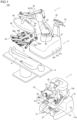
FIG. 1 is a diagram showing the configuration of a robotic surgical system according to an embodiment. -
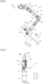
FIG. 2 is a diagram showing the configuration of a robot arm according to the embodiment. -
FIG. 3 is a diagram showing a pair of forceps. -
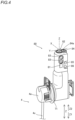
FIG. 4 is a perspective view showing the configuration of an arm operation unit according to the embodiment. -
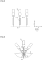
FIG. 5 is a diagram for illustrating translational movement of the robot arm. -
FIG. 6 is a diagram for illustrating rotational movement of the robot arm. -
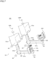
FIG. 7 is a diagram showing an operation unit according to the embodiment. -
FIG. 8 is a diagram showing the configuration of a right-handed operation unit according to the embodiment. -
FIG. 9 is a diagram showing the configuration of a left-handed operation unit according to the embodiment. -
FIG. 10 is a diagram showing the configuration of foot pedals according to the embodiment. -
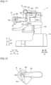
FIG. 11 is a side view of a remote control apparatus according to the embodiment. -
FIG. 12 is a diagram showing a state in which a monitor is tilted. -
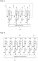
FIG. 13 is a control block diagram of the robotic surgical system according to the embodiment. -
FIG. 14 is a control block diagram of the robot arm according to the embodiment. -
FIG. 15 is a control block diagram of the remote control apparatus according to the embodiment. -
FIG. 16 is a diagram showing an operator and an HC coordinate system. -
FIG. 17 is a diagram showing a surgical instrument, an endoscope, and an endoscope coordinate system. -
FIG. 18 is a diagram for illustrating operations performed when the operation unit receives an operation. -
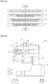
FIG. 19 is a flowchart of a control method for the robotic surgical system according to the embodiment. -
FIG. 20 is a side view of a remote control apparatus according to a modified example. - The configuration of a robotic
surgical system 100 according to this embodiment is now described. The roboticsurgical system 100 includes asurgical robot 1 and aremote control apparatus 2. Thesurgical robot 1 and theremote control apparatus 2 are examples of a surgical apparatus and an operation apparatus, respectively. - In this specification, the longitudinal direction of a
shaft 4c of asurgical instrument 4 is defined as a Z direction, as shown inFIG. 2 . The distal end side of thesurgical instrument 4 is defined as a Z1 side, and the proximal end side of thesurgical instrument 4 is defined as a Z2 side. A direction perpendicular to the Z direction is defined as an X direction. A direction perpendicular to the Z direction and the X direction is defined as a Y direction. - In this specification, as shown in
FIG. 8 , a direction along a vertical direction is defined as a Za direction. In the Za direction, a first side is defined as a Za1 side, and a second side is defined as a Za2 side. A direction perpendicular to the Z direction is defined as an Xa direction. In the Xa direction, a first side is defined as an Xa1 side, and a second side is defined as an Xa2 side. A direction perpendicular to the Za direction and the Xa direction is defined as a Ya direction. In the Ya direction, a first side is defined as a Ya1 side, and a second side is defined as a Ya2 side. The Xa direction and the Ya direction are directions along a horizontal plane. - As shown in
FIG. 1 , thesurgical robot 1 is arranged in an operating room. Theremote control apparatus 2 is spaced apart from thesurgical robot 1. An operator such as a doctor inputs a command to theremote control apparatus 2 to cause thesurgical robot 1 to perform a desired operation. Theremote control apparatus 2 transmits the input command to thesurgical robot 1. Thesurgical robot 1 operates based on the received command. Thesurgical robot 1 is arranged in the operating room that is a sterilized sterile field. - As shown in
FIG. 1 , thesurgical robot 1 includes amedical cart 3, apositioner 40, anarm base 50, a plurality ofrobot arms 60, andarm operation units 80. - The
medical cart 3 moves thepositioner 40. Themedical cart 3 includes aninput 33. Theinput 33 receives operations to move thepositioner 40, thearm base 50, and the plurality ofrobot arms 60 or change their postures mainly in order to prepare for surgery before the surgery. Themedical cart 3 includes anoperation handle 34 to receive an operator's steering operation. - The
positioner 40 includes a 7-axis articulated robot, for example. Thepositioner 40 is arranged on themedical cart 3. Thepositioner 40 adjusts the position of thearm base 50. Thepositioner 40 moves the position of thearm base 50 three-dimensionally. - The
positioner 40 includes abase 41 and a plurality oflinks 42 coupled to thebase 41. The plurality oflinks 42 are connected to each other byjoints 43. - The
arm base 50 is attached to a distal end of thepositioner 40. A proximal end of each of the plurality ofrobot arms 60 is attached to thearm base 50. Each of the plurality ofrobot arms 60 is able to take a folded and stored posture. Thearm base 50 and the plurality ofrobot arms 60 are covered with sterile drapes and used. Moreover, each of therobot arms 60 supports thesurgical instrument 4. - The plurality of
robot arms 60 are arranged. Specifically, fourrobot arms robot arms robot arms robot arm 60c is an example of a first robot arm. - As shown in
FIG. 2 , eachrobot arm 60 includes anarm portion 61, afirst link 72, asecond link 73, and atranslation mechanism 70. Therobot arm 60 includes a JT1 axis, a JT2 axis, a JT3 axis, a JT4 axis, a JT5 axis, a JT6 axis, and a JT7 axis as rotation axes and a J8 axis as a linear motion axis. The JT1 axis, the JT2 axis, the JT3 axis, the JT4 axis, the JT5 axis, the JT6 axis, and the JT7 axis are rotation axes ofjoints 64 of thearm portion 61. Furthermore, the JT7 axis is a rotation axis of thefirst link 72. The JT8 axis is a linear motion axis along which thetranslation mechanism 70 moves thesecond link 73 relative to thefirst link 72 along the Z direction. - The
arm portion 61 includes a 7-axis articulated robot arm. Thefirst link 72 is arranged at a distal end of thearm portion 61. Anarm operation unit 80 is attached to thesecond link 73. Thetranslation mechanism 70 is arranged between thefirst link 72 and thesecond link 73. Aholder 71 that holds thesurgical instrument 4 is arranged on thesecond link 73. - The
surgical instrument 4 is attached to a distal end of each of the plurality ofrobot arms 60. Thesurgical instrument 4 includes a replaceable instrument, or anendoscope 6 to capture an image of a surgical site, for example. Thesurgical instrument 4 as the instrument includes a drivenunit 4a, a pair offorceps 4b, and theshaft 4c that connects the drivenunit 4a to the pair offorceps 4b. The drivenunit 4a, theshaft 4c, and the pair offorceps 4b are arranged along the Z direction. - As shown in
FIG. 1 , theendoscope 6 is attached to the distal end of one of the plurality ofrobot arms 60, such as therobot arm 60c, andsurgical instruments 4 other than theendoscope 6 are attached to the distal ends of the remainingrobot arms endoscope 6 is attached to one of tworobot arms robot arms 60 arranged adjacent to each other. - As shown in
FIG. 3 , the pair offorceps 4b is arranged at a distal end of the instrument, for example. At the distal end of the instrument, in addition to the pair offorceps 4b, a pair of scissors, a grasper, a needle holder, a microdissector, a stable applier, a tacker, a suction cleaning tool, a snare wire, a clip applier, etc. are arranged as instruments having joints. At the distal end of the instrument, a cutting blade, a cautery probe, a washer, a catheter, a suction orifice, etc. are arranged as instruments having no joint. - The pair of
forceps 4b includes afirst support 4e that supports the proximal end sides ofjaw members jaw members second support 4f that supports the proximal end side of thefirst support 4e on the distal end side such that the proximal end side of thefirst support 4e is rotatable about a JT10 axis. Theshaft 4c rotates about a JT9 axis. Thejaw members first support 4e on the Z1 direction side, that is the distal end side, has a U-shape. - As shown in
FIG. 2 , thearm operation unit 80 is attached to therobot arm 60. Specifically, thearm operation unit 80 is attached to thesecond link 73. - As shown in
FIG. 4 , thearm operation unit 80 includes an enableswitch 81, ajoystick 82, andlinear switches 83, amode switching button 84, amode indicator 84a, apivot button 85, and anadjustment button 86. - The enable
switch 81 enables or disables movement of therobot arm 60 in response to thejoystick 82 and the linear switches 83. Thejoystick 82 is an operation tool to control movement of thesurgical instrument 4 by therobot arm 60. Thelinear switches 83 are switches to move thesurgical instrument 4 in a direction along the longitudinal direction of thesurgical instrument 4. Themode switching button 84 is a button to switch between a mode for translationally moving thesurgical instrument 4 as shown inFIG. 5 and a mode for rotationally moving thesurgical instrument 4 as shown inFIG. 6 . Themode indicator 84a indicates a switched mode. Thepivot button 85 is a button to teach the pivot position PP that serves as a fulcrum for movement of thesurgical instrument 4 attached to therobot arm 60. Theadjustment button 86 is a button to optimize the position of therobot arm 60. - As shown in
FIG. 1 , theremote control apparatus 2 is arranged inside or outside the operating room, for example. Theremote control apparatus 2 includes amain body 2a,operation units 120,foot pedals 22, atouch panel 23, amonitor 24, asupport arm 25, asupport bar 26,foot detectors 27, anangle sensor 29a shown inFIG. 11 , and switches 29b shown inFIG. 11 . Themonitor 24 is an example of a display. Theangle sensor 29a is an example of a tilt detection sensor. - As shown in
FIG. 1 , theoperation units 120 receive operations for theendoscope 6 or thesurgical instruments 4 other than theendoscope 6. Theoperation units 120 are supported by themain body 2a. As shown inFIG. 7 , theoperation units 120 includes a left-handed operation unit 120L that is located on the left side as viewed from the operator such as a doctor and is to be operated by the left hand of the operator, and a right-handed operation unit 120R that is located on the right side and is to be operated by the right hand of the operator. The left-handed operation unit 120L and the right-handed operation unit 120R have the same or similar configurations as each other. - The
operation units 120 include substantially L-shapedarms 121 and operation handles 21. Thearms 121 each include alink 121a, alink 121b, and alink 121c. The upper end side of thelink 121a is attached to themain body 2a such that thelink 121a is rotatable about an A1 axis along the vertical direction. The upper end side of thelink 121b is attached to the lower end side of thelink 121a such that thelink 121b is rotatable about an A2 axis along a horizontal direction. A first end side of thelink 121c is attached to the lower end side of thelink 121b such that thelink 121c is rotatable about an A3 axis along the horizontal direction. The operation handle 21 is attached to a second end side of thelink 121c such that the operation handle 21 is rotatable about an A4 axis. The links are connected to each other byjoints 122. - The
arm 121 supports theoperation handle 21. Thearm 121 supports the operation handle 21 such that the operation handle 21 is movable within a predetermined three-dimensional operation range. Specifically, thearm 121 supports the operation handle 21 such that the operation handle 21 is movable in an upward-downward direction, a right-left direction, and a forward-rearward direction. Therobot arm 60 is moved three-dimensionally so as to correspond to a three-dimensional operation on thearm 121. - The operation handles 21 include an
operation handle 21R shown inFIG. 8 to be operated by the right hand of the operator, and anoperation handle 21L shown inFIG. 9 to be operated by the left hand of the operator.FIG. 8 shows the reference position of the right-handed operation unit 120R, andFIG. 9 shows the reference position of the left-handed operation unit 120L. The operation handle 21R and the operation handle 21L have the same or similar configurations as each other. The operation handles 21 each include alink 21a, alink 21b, alink 21c, and alink 21d operated by the operator such as a doctor. Thelink 21a rotates about the A4 axis. Thelink 21b is attached to thelink 21a so as to be rotatable about an A5 axis. Thelink 21c is attached to thelink 21b so as to be rotatable about an A6 axis. Thelink 21d is attached to thelink 21c so as to be rotatable about an A7 axis. The links are connected to each other byjoints 122. Each of thelinks - The operation handles 21 each includes a pair of
grip members 21f to be opened and closed by the operator. Thegrip members 21f each include an elongated plate-shaped lever member, and proximal ends of the pair ofgrip members 21f are rotatably connected to a proximal end G1 of thelink 21d. Cylindricalfinger insertion portions 21e are provided on thegrip members 21f. The operator inserts his/her right fingers into a pair offinger insertion portions 21e to operate the operation handle 21R. The operator inserts his/her left fingers into a pair offinger insertion portions 21e to operate the operation handle 21L. The proximal ends of the pair ofgrip members 21f are connected to thelink 21d, and an angle between the pair ofgrip members 21f is increased or decreased such that an opening angle between thejaw member 104a and thejaw member 104b is changed. A magnet is provided on one of thegrip members 21f, and a Hall sensor is provided on thelink 21d. When the operator opens and closes thegrip members 21f, the magnet and the Hall sensor function as an angle detection sensor, and the Hall sensor outputs the opening angle. As the angle detection sensor, the Hall sensor may be provided on thegrip member 21f, and the magnet may be provided on thelink 21d. Alternatively, the magnet or the Hall sensor may be provided as the angle detection sensor on both thegrip members 21f. - The intersection of a plurality of rotation axes of the
operation unit 120 is called a gimbal point GP. Specifically, the gimbal point GP is a point at which the A4 axis, the A5 axis, the A6 axis, and the A7 axis intersect with each other. The gimbal point GP is located in thelink 21d to which the pair ofgrip members 21f are attached. The gimbal point GP exists individually in each of the left-handed operation unit 120L and the right-handed operation unit 120R. - As shown in
FIG. 10 , a plurality offoot pedals 22 are provided to perform functions related to thesurgical instruments 4. The plurality offoot pedals 22 are arranged on abase 28. Thefoot pedals 22 include a switching pedal 22a, aclutch pedal 22b, acamera pedal 22c, anincision pedal 22d, and acoagulation pedal 22e. The switching pedal 22a, theclutch pedal 22b, thecamera pedal 22c, theincision pedal 22d, and thecoagulation pedal 22e are operated by the foot of the operator. Theincision pedal 22d includes an incision pedal 22dR for aright robot arm 60, and an incision pedal 22dL for aleft robot arm 60. Thecoagulation pedal 22e includes a coagulation pedal 22eR for theright robot arm 60 and a coagulation pedal 22eL for theleft robot arm 60. - The switching pedal 22a switches the
robot arms 60 to be operated by the operation handles 21. Theclutch pedal 22b performs a clutch operation to temporarily disconnect an operation connection between therobot arms 60 and the operation handles 21. While theclutch pedal 22b is being pressed by the operator, operations by the operation handles 21 are not transmitted to therobot arms 60. While thecamera pedal 22c is being pressed by the operator, the operation handle 21 can operate arobot arm 60 to which theendoscope 3 is attached. While theincision pedal 22d or thecoagulation pedal 22e is being pressed by the operator, an electrosurgical device is activated. - The
foot detectors 27 detect the foot of the operator that operates thefoot pedals 22. Thefoot detectors 27 detect the foot that hovers above theircorresponding foot pedals 22. Thefoot detectors 27 are arranged on thebase 28. - As shown in
FIG. 11 , themonitor 24 is a scope-type display that displays an image captured by theendoscope 6. As shown inFIG. 12 , themonitor 24 rotates so as to be tilted with respect to the horizontal plane. Specifically, themonitor 24 rotates about a D1 axis along the Xa direction. The D1 axis is an example of a first axis. - As shown in
FIG. 11 , thesupport arm 25 supports themonitor 24 so as to align the height of themonitor 24 with the height of the face of the operator such as a doctor. Thesupport arm 25 includes afirst link 25a, asecond link 25b, athird link 25c, and grips 25d. A first end of thefirst link 25a is attached to themain body 2a. A joint JT21 is disposed at the first end of thefirst link 25a. A second end of thefirst link 25a is connected to a first end of thesecond link 25b by a joint JT22. A second end of thesecond link 25b is connected to a first end of thethird link 25c by a joint JT23. Themonitor 24 is rotatably attached to thethird link 25c. Thegrips 25d are arranged at thethird link 25c. Thegrips 25d are arranged on both the Xa1 side and the Xa2 side of thethird link 25c. Thefirst link 25a and thesecond link 25b are examples of a link. Thethird link 25c is an example of a link or a holder. - A spring SP1 is arranged at a proximal end of the
first link 25a. Thefirst link 25a is lifted by the spring SP1. A spring SP2 is arranged at thefirst link 25a. Thesecond link 25b is lifted by the spring SP2. A spring SP3 is arranged at thesecond link 25b. Thethird link 25c is lifted by the spring SP3. A brake BRK1 is arranged on the proximal end side of thefirst link 25a. The brake BRK1 fixes the joint JT21 such that the joint JT21 does not rotate. A brake BRK2 is arranged at the joint JT23 by which thesecond link 25b is connected to thethird link 25c. The brake BRK2 fixes the joint JT23 such that the joint JT23 does not rotate. The springs SP1, SP2, and SP3 are arranged to support the weights of thesupport arm 25 and themonitor 24. The brakes BRK1 and BRK2 are electromagnetic brakes that are activated without excitation and prevent the joints JT21 and JT23 from moving even when an external force is applied thereto. Only one or two of the springs SP1, SP2, and SP3 may be provided. Furthermore, only the brake BRK1 or the brake BRK2 may be provided. Alternatively, a brake may be provided at the joint JT22. - In this embodiment, the
switches 29b switch between a state in which a change in the posture of thesupport arm 25 is permitted and a state in which the change in the posture is not permitted. Theswitches 29b are arranged on thegrips 25d. When the operator presses theswitches 29b, the brakes BRK1 and BRK2 are released, and the operator can change the posture of thesupport arm 25 by gripping and moving thegrips 25d. The operator can change the tilt angle of themonitor 24 with respect to the horizontal plane by gripping and tilting thegrips 25d. A brake BRK3 may be provided to fix rotation of themonitor 24 and thethird link 25c. When the operator presses theswitches 29b, the brake BRK3 may be released such that the tilt angle of themonitor 24 with respect to the horizontal plane can be changed in addition to changing the posture of thesupport arm 25. - In this embodiment, the
angle sensor 29a detects the tilt of themonitor 24 with respect to the horizontal plane. Themonitor 24 rotates about the D1 axis with respect to thethird link 25c. Theangle sensor 29a detects the rotation angle θ of themonitor 24 about the D1 axis along the horizontal plane. Theangle sensor 29a detects the rotation angle θ of themonitor 24 with respect to thethird link 25c. Theangle sensor 29a is an encoder that detects the rotation angle θ of themonitor 24, for example. - As shown in
FIG. 1 , thetouch panel 23 is arranged on thesupport bar 26. When a sensor provided in the vicinity of themonitor 24 detects the head of the operator, the operator is enabled to operate thesurgical robot 1 using theremote control apparatus 2. The operator operates theoperation units 120 and thefoot pedals 22 while visually recognizing an affected area on themonitor 24. Thus, a command is input to theremote control apparatus 2. The command input to theremote control apparatus 2 is transmitted to thesurgical robot 1. Thesupport arm 25 is an example of a support. - As shown in
FIG. 13 , the roboticsurgical system 100 includes acontrol device 130, anarm controller 31a, apositioner controller 31b, andoperation controllers 110. - The
control device 130 is accommodated in themedical cart 3 to communicate with thearm controller 31a and thepositioner controller 31b, and controls the entire roboticsurgical system 100. Specifically, thecontrol device 130 communicates with and controls thearm controller 31a, thepositioner controller 31b, and theoperation controllers 110. Thecontrol device 130 is connected to thearm controller 31a, thepositioner controller 31b, and theoperation controllers 110 through a LAN, for example. Thecontrol device 130 is arranged inside themedical cart 3. - The
arm controller 31a is arranged for each of the plurality ofrobot arms 60. That is, the same number ofarm controllers 31a as the plurality ofrobot arms 60 are placed inside themedical cart 3. - As shown in
FIG. 13 , theinput 33 is connected to thecontrol device 130 through a LAN, for example. Astatus indicator 53, anarm status indicator 54, theoperation handle 34, athrottle 34a, a joystick 33b, astabilizer 34c, and anelectric cylinder 34d are connected to thepositioner controller 31b via awire line 145 by means of a communication network that allows information to be shared with each other by using serial communication. AlthoughFIG. 13 shows that thestatus indicator 53, thearm status indicator 54, etc. are all connected to onewire line 145, in reality, thewire line 145 is arranged for each of thestatus indicator 53, thearm status indicator 54, theoperation handle 34, thethrottle 34a, the joystick 33b, thestabilizer 34c, and theelectric cylinder 34d. - As shown in
FIG. 14 , thearm portion 61 includes a plurality of servomotors M1, encoders E1, and speed reducers so as to correspond to a plurality ofjoints 64. The encoders E1 detect rotation angles of the servomotors M1. The speed reducers slow down rotation of the servomotors M1 to increase the torques. Inside themedical cart 3, servo controllers C1 that control the servomotors M1 are arranged adjacent to thearm controller 31a. In addition, the encoders E1 that detect the rotation angles of the servomotors M1 are electrically connected to the servo controllers C1. - Servomotors M2 that rotate driven members provided in the driven
unit 4a of thesurgical instrument 4, encoders E2, and speed reducers are arranged in thesecond link 73. The encoders E2 detect rotation angles of the servomotors M2. The speed reducers slow down rotation of the servomotors M2 to increase the torques. In themedical cart 3, servo controllers C2 are provided to control the servomotors M2 to drive thesurgical instrument 4. The encoders E2 that detect the rotation angles of the servomotors M2 are electrically connected to the servo controllers C2. A plurality of servomotors M2, a plurality of encoders E2, and a plurality of servo controllers C2 are arranged. - The
translation mechanism 70 includes a servomotor M3 to translationally move thesurgical instrument 4, an encoder E3, and a speed reducer. The encoder E3 detects a rotation angle of the servomotor M3. The speed reducer slows down rotation of the servomotor M3 to increase the torque. In themedical cart 3, a servo controller C3 is provided to control the servomotor M3 to translationally move thesurgical instrument 4. The encoder E3 that detects the rotation angle of the servomotor M3 is electrically connected to the servo controller C3. - As shown in
FIG. 13 , thepositioner controller 31b is arranged in themedical cart 3. Thepositioner controller 31b controls thepositioner 40 and themedical cart 3. Servomotors SM, encoders EN, speed reducers, and servo controllers SC are provided in thepositioner 40 so as to correspond to a plurality ofjoints 43 of thepositioner 40. Servomotors SM that drive a plurality of front wheels of themedical cart 3, encoders EN, speed reducers, servo controllers SC, and brakes are provided in themedical cart 3. - As shown in
FIG. 15 , servomotors M6a, M6b, M6c, M6d, M6e, M6f, and M6g are provided in theoperation units 120 so as to correspond to the A1 axis, the A2 axis, the A3 axis, the A4 axis, the A5 axis, the A6 axis, and the A7 axis, which are rotation axes, respectively. Servo controllers C6a, C6b, C6c, C6d, C6e, C6f, and C6g are provided in themedical cart 3 to control the servomotors. Encoders E6a, E6b, E6c, E6d, E6e, E6f, and E6g that detect rotation angles of the servomotors are electrically connected to the servo controllers, respectively. The servomotors, the servo controllers, and the encoders are provided in each of the left-handed operation unit 120L and the right-handed operation unit 120R. - The
control device 130 controls the servomotors via theoperation controllers 110 to generate torques that cancel gravitational torques generated on the rotation axes of the servomotors according to the postures of theoperation units 120. Thus, the operator can operate theoperation units 120 with a relatively small force. - The
control device 130 generates torques on the rotation axes of the servomotors according to operations on theoperation units 120 via theoperation controllers 110, and controls the servomotors to assist the operation of the operator. Thus, the operator can operate theoperation units 120 with a relatively small force. - The
control device 130 performs a control to move theendoscope 6 or thesurgical instrument 4 other than theendoscope 6 based on operations received by theoperation units 120. Specifically, as shown inFIGS. 8 and 9 , thecontrol device 130 sets an operation unit reference point MP for each of theoperation units 120. The operation unit reference point MP is also called a mapping point. The operation unit reference point MP is set at the gimbal point GP, for example. Thecontrol device 130 sets a surgical instrument reference point CP shown inFIG. 3 for thesurgical instrument 4. When theoperation unit 120 is operated, thecontrol device 130 performs a control to move thesurgical instrument 4 such that the surgical instrument reference point CP moves in response to movement of the operation unit reference point MP. The operation of moving thesurgical instrument 4 such that the surgical instrument reference point CP moves in response to movement of the operation unit reference point MP is called following. As shown inFIG. 3 , the surgical instrument reference point CP is set at the center of a Z1 direction side portion of thefirst support 4e in a JT11 axis direction. The surgical instrument reference point CP is called a tool center point or a clevis point. - As shown in
FIG. 16 , a coordinate system of theoperation unit 120 is set in theoperation unit 120. Hereinafter, the coordinate system of theoperation unit 120 is referred to as an HC coordinate system. As shown inFIG. 17 , a coordinate system of theendoscope 6 is set in theendoscope 6. Hereinafter, the coordinate system of theendoscope 6 is referred to as an endoscope coordinate system. For example, when the operator moves theoperation unit 120 along the Yb direction of the HC coordinate system, thesurgical instrument 4 moves along the Yc direction of the endoscope coordinate system, which is a direction in which theendoscope 6 extends. - The inventors of the present disclosure have found that a direction in which the operator operates the
operation unit 120 changes due to a change in the direction of the line of sight of the operator viewing themonitor 24. For example, assume that the operator attempts to translationally move thesurgical instrument 4 along the Yc direction of the endoscope coordinate system when themonitor 24 is tilted obliquely downward. At this time, it has been found that the operator moves theoperation unit 120 obliquely downward intersecting with the Yb direction as shown by a translation vector uh inFIG. 16 , instead of the Yb direction of the HC coordinate system. Therefore, thesurgical instrument 4 is translationally moved in a direction different from a direction intended by the operator. Note that uh inFIG. 16 is a translation vector that indicates a direction in which theoperation unit 120 is moved as viewed from the HC coordinate system. - Therefore, in this embodiment, the
control device 130 corrects translational movement of thesurgical instrument 4 based on the tilt detected by theangle sensor 29a. Thesurgical instrument 4 is an instrument with the pair offorceps 4b arranged at the distal end, for example. Specifically, when a translational movement operation for thesurgical instrument 4 is received, thecontrol device 130 corrects a direction of the translational movement of thesurgical instrument 4 based on the tilt detected by theangle sensor 29a such that thesurgical instrument 4 translationally moves along the direction in which theendoscope 6 extends. That is, even when the translation vector uh of theoperation unit 120 is directed obliquely upward, thecontrol device 130 corrects a translation vector uf such that the translation vector uf follows the Yc direction of the endoscope coordinate system. Note that uf is a translation vector that indicates the movement direction of the pair offorceps 4b as viewed from a robot reference coordinate system. - When the
monitor 24 is arranged along the horizontal plane, thecontrol device 130 does not correct the direction of the translational movement of thesurgical instrument 4 when an operation is received to translationally move thesurgical instrument 4 along the forward-rearward direction as viewed by the operator. That is, when themonitor 24 is arranged along the horizontal plane, thecontrol device 130 translationally moves thesurgical instrument 4 such that thesurgical instrument 4 translationally moves along the Yc direction of the endoscope coordinate system when an operation is received to translationally move thesurgical instrument 4 along the Yb direction of the HC coordinate system. - In this embodiment, as shown in the following equation (1), when a translational movement operation for the
surgical instrument 4 is received, thecontrol device 130 corrects the direction of the translational movement of thesurgical instrument 4 based on a posture term that represents the posture of theendoscope 6 based on the coordinate system of theendoscope 6 and a correction term that corrects the posture term based on the tilt detected by theangle sensor 29a. Specifically, when a translational movement operation for thesurgical instrument 4 is received, the control device 310 corrects the translation vector uf of thesurgical instrument 1 by multiplying the translation vector uh of thesurgical instrument 1 based on the coordinate system of theoperation unit 120 by a posture matrix Hcam of theendoscope 3 based on the coordinate system of theendoscope 3 and a posture correction matrix Rx based on the tilt detected by theangle sensor 29a.
- Hcam represents a posture matrix in a camera coordinate system as viewed from the robot reference coordinate system. Rx represents a posture correction matrix according to the rotation angle θ of the
monitor 24 about the D1 axis. Rx varies according to the rotation angle θ. Furthermore, Rx corresponds to the tilt of themonitor 24 with respect to the horizontal plane. That is, thecontrol device 130 corrects the translational movement of thesurgical instrument 1 based on the rotation angle θ about the D1 axis detected by theangle sensor 29a. - In this embodiment, the
control device 130 corrects the translational movement of thesurgical instrument 4 based on the tilt detected by theangle sensor 29a during surgery in which an operation for thesurgical instrument 4 is received by theremote control apparatus 2. Specifically, thecontrol device 130 corrects the translational movement of thesurgical instrument 4 based on the tilt detected by theangle sensor 29a while the following, which is the operation of moving thesurgical instrument 4, is being performed. When the operator presses theswitches 29b during surgery to change the tilt angle of themonitor 24 with respect to the horizontal plane, Rx in the above equation (1) is changed so as to correspond to the changed tilt angle of themonitor 24. Then, the translational movement of thesurgical instrument 4 is corrected based on the changed Rx. - A method for calculating an input value of the
operation unit 120 when an operation of the operator is received is now described. As shown inFIG. 18 , the operation of the operator is received by theoperation unit 120. Thus, the axis values of the A1 axis, the A2 axis, the A3 axis, the A4 axis, the A5 axis, the A6 axis, and the A7 axis of theoperation unit 120 are input to theoperation controller 110. Thecontrol device 130 performs a forward kinematic calculation based on each axis value input to theoperation controller 110. Thus, a homogeneous transformation matrix that represents the displacement and rotation of the operation unit reference point MP from the reference posture is updated as an input value from theoperation unit 120. The forward kinematic calculation is means for calculating, from the axis values of a link mechanism, the displacement and rotation of a focused portion of the mechanism. Thecontrol device 130 converts the homogeneous transformation matrix that represents the input from theoperation unit 120 according to the viewing direction of theendoscope 6. At this time, the translational movement of thesurgical instrument 4 is corrected based on the above equation (1). The obtained homogeneous transformation matrix includes a translational component for the translational movement of thesurgical instrument 4 and a rotational component for the rotation of thesurgical instrument 4, which generate a movement corresponding to the input of theoperation unit 120 within the field of view of theendoscope 6. Thecontrol device 130 performs scaling on the translational component and the rotational component. The term "scaling" refers to multiplying the translational component and the rotational component by a scaling value, which is a ratio between an operation amount received by theoperation unit 120 and the actual movement amount of thesurgical instrument 4. Thecontrol device 130 calculates a target homogeneous transformation matrix based on the scaled translational component and rotational component. Thecontrol device 130 performs an inverse kinematic calculation on the target homogeneous transformation matrix. Thecontrol device 130 calculates each axis value that is the target of therobot arm 60 and thesurgical instrument 4 by the inverse kinematic calculation. - A control method for the robotic
surgical system 100 is now described. - As shown in
FIG. 19 , in step S1, theangle sensor 29a detects the tilt of themonitor 24 with respect to the horizontal plane. - In step S2, the
operation unit 120 receives an operation for thesurgical instrument 4. - In step S3, the
control device 130 corrects the translation vector of thesurgical instrument 4 using the above equation (1) based on the detected tilt. - In step S4, the
control device 130 performs a control to move thesurgical instrument 4 based on the corrected translation vector. - The
control device 130 is configured or programmed to correct translational movement of thesurgical instrument 4 based on the tilt detected by theangle sensor 29a to detect the tilt of themonitor 24 with respect to the horizontal plane. Accordingly, even when the tilt of themonitor 24 with respect to the horizontal plane changes, the translational movement of thesurgical instrument 4 is corrected by thecontrol device 130. Therefore, even when the tilt of themonitor 24 changes, thesurgical instrument 4 can be accurately translationally moved in the desired direction intended by the operator. Furthermore, the tilt of themonitor 24 with respect to the horizontal plane can be relatively easily detected by theangle sensor 29a. Therefore, even when the tilt of themonitor 24 changes, thesurgical instrument 4 can be accurately translationally moved in the desired direction intended by the operator while the tilt of themonitor 24 with respect to the horizontal plane is easily detected. - The
control device 130 is configured or programmed to correct the direction of the translational movement of thesurgical instrument 4 based on the tilt detected by theangle sensor 29a such that thesurgical instrument 4 translationally moves along the direction in which theendoscope 6 extends when a translational movement operation for thesurgical instrument 4 is received. Accordingly, even when the tilt of themonitor 24 changes, thesurgical instrument 4 can be accurately translationally moved along the direction in which theendoscope 6 extends. - The
control device 130 is configured or programmed to correct the direction of the translational movement of thesurgical instrument 4 based on the posture term that represents the posture of theendoscope 6 based on the coordinate system of theendoscope 6 and the correction term that corrects the posture term based on the tilt detected by theangle sensor 29a when a translational movement operation for thesurgical instrument 4 is received. Accordingly, the posture term that represents the posture of theendoscope 6 is corrected by the correction term based on the tilt detected by theangle sensor 29a, and thus thesurgical instrument 4 can be appropriately translationally moved to follow the posture of theendoscope 6. - The
control device 130 is configured or programmed to correct the translation vector uf of thesurgical instrument 4 by multiplying the translation vector uh of thesurgical instrument 4 based on the coordinate system of theoperation unit 120 by the posture matrix Hcam of theendoscope 6 based on the coordinate system of theendoscope 6 and the posture correction matrix Rx based on the tilt detected by theangle sensor 29a when a translational movement operation for thesurgical instrument 4 is received. Accordingly, the translation vector uf of thesurgical instrument 4 is corrected by the posture matrix Hcam of theendoscope 6 and the posture correction matrix Rx, and thus thesurgical instrument 4 can be appropriately translationally moved to follow the posture of theendoscope 6. - The
remote control apparatus 2 includes thesupport arm 25 to support themonitor 24. Thesupport arm 25 includes thefirst link 25a, thesecond link 25b, thethird link 25c, the joints JT21, JT22, and JT23, the brake BRK1 to fix the joint JT21 such that the joint JT21 does not rotate, the brake BRK2 to fix the joint JT23 such that the joint JT23 does not rotate, the spring SP1 to lift thefirst link 25a, the spring SP2 to lift thesecond link 25b, and the spring SP3 to lift thethird link 25c. Accordingly, even when an external force is applied to thesupport arm 25, the joints JT21 and JT23 can be fixed by the brakes BRK1 and BRK2 so as not to move. Furthermore, the weights of thesupport arm 25 and themonitor 24 are supported by the springs SP1, SP2, and SP3, and thus the posture of thesupport arm 25 is maintained. - The
control device 130 is configured or programmed to correct the translational movement of thesurgical instrument 4 based on the tilt detected by theangle sensor 29a during surgery in which an operation for thesurgical instrument 4 is received by theremote control apparatus 2. Accordingly, even when the tilt of themonitor 24 is changed during surgery, thesurgical instrument 4 can be translationally moved in the desired direction intended by the operator. - The
angle sensor 29a is operable to detect the rotation angle θ of themonitor 24 about the D1 axis along the horizontal plane, and thecontrol device 130 is configured or programmed to correct the translational movement of thesurgical instrument 4 based on the rotation angle θ about the D1 axis detected by theangle sensor 29a. Accordingly, the tilt of themonitor 24 with respect to the horizontal plane can be easily detected based on the rotation angle θ of themonitor 24 about the D1 axis. - The
remote control apparatus 2 includes theswitches 29b to switch between a state in which a change in the tilt angle of themonitor 24 with respect to the horizontal plane is permitted and a state in which the change in the tilt angle is not permitted. Accordingly, a change in the tilt of themonitor 24 at the timing unintended by the operator can be reduced or prevented by theswitches 29b. - The embodiment disclosed this time must be considered as illustrative in all points and not restrictive. The scope of the present disclosure is not shown by the above description of the embodiment but by the scope of claims for patent, and all modifications or modified examples within the meaning and scope equivalent to the scope of claims for patent are further included.
- While the example in which the direction of translational movement of the
surgical instrument 4 is corrected such that thesurgical instrument 4 translationally moves along the Yc direction of the endoscope coordinate system in which theendoscope 6 extends has been shown in the aforementioned embodiment, the present disclosure is not limited to this. For example, the direction of translational movement of thesurgical instrument 4 may be corrected such that thesurgical instrument 4 translationally moves along a direction other than the Yc direction of the endoscope coordinate system. - While the example in which the translation vector is corrected based on the above equation (1) has been shown in the aforementioned embodiment, the present disclosure is not limited to this. In the present disclosure, the translation vector may be corrected based on an equation other than the above equation (1).
- While the example in which the translational movement of the
surgical instrument 4 is corrected when an operation for thesurgical instrument 4 is received by theremote control apparatus 2 has been shown in the aforementioned embodiment, the present disclosure is not limited to this. For example, based on an operation of the operator, a state in which the translational movement of thesurgical instrument 4 is corrected and a state in which the translational movement of thesurgical instrument 4 is not corrected may be switched. - While the example in which the
control device 130 corrects the translational movement of thesurgical instrument 4 based on the rotation angle θ of themonitor 24 about the D1 axis detected by theangle sensor 29a has been shown in the aforementioned embodiment, the present disclosure is not limited to this. For example, anacceleration sensor 201 may be arranged as in aremote control apparatus 200 according to a modified example shown inFIG. 20 . Theacceleration sensor 201 is arranged at amonitor 24 on the Ya1 direction end side of athird link 25c of theremote control apparatus 200. Theacceleration sensor 201 detects at least the tilt of themonitor 24 with respect to a horizontal plane. Specifically, theacceleration sensor 201 detects the rotation angles of themonitor 24 about a D1 axis along the horizontal plane, a D2 axis along the horizontal plane and perpendicular to the D1 axis, and a D3 axis along a vertical direction. Thus, the tilt of themonitor 24 can be easily detected by theacceleration sensor 201. Furthermore, theacceleration sensor 201 can easily detect a three-dimensional change in the tilt of themonitor 24. Acontrol device 130 corrects translational movement of asurgical instrument 4 based on the rotation angles about the D1 axis, the D2 axis, and the D3 axis detected by theacceleration sensor 201. Accordingly, even when the tilt of themonitor 24 is changed three-dimensionally, thesurgical instrument 4 can be accurately translationally moved in a desired direction intended by an operator. Specifically, the translational movement of thesurgical instrument 4 is corrected based on the following equation (2).
- Mcomp represents a posture correction matrix that is changed according to the rotation angles of the
monitor 24 about the D1, D2, and D3 axes. Theacceleration sensor 201 is an example of a tilt detection sensor. The D2 axis and the D3 axis are examples of a second axis and a third axis, respectively. - While the example in which the
switches 29b switch between a state in which a change in the tilt angle of themonitor 24 with respect to the horizontal plane is permitted and a state in which the change in the tilt angle is not permitted has been shown in the aforementioned embodiment, the present disclosure is not limited to this. For example, theswitches 29b may not be provided, and the tilt angle of themonitor 24 may be freely changed by the operator. - While the example in which four
robot arms 60 are provided has been shown in the aforementioned embodiment, the present disclosure is not limited to this. In the present disclosure, the number ofrobot arms 60 may be any number as long as at least onerobot arm 60 is provided. - While the example in which each of the
arm portion 61 and thepositioner 40 includes a 7-axis articulated robot has been shown in the aforementioned embodiment, the present disclosure is not limited to this. For example, each of thearm portion 61 and thepositioner 40 may include an articulated robot having an axis configuration other than the 7-axis articulated robot. The axis configuration other than the 7-axis articulated robot includes six axes or eight axes, for example. - While the example in which the
surgical robot 1 includes themedical cart 3, thepositioner 40, and thearm base 50 has been shown in the aforementioned embodiment, the present disclosure is not limited to this. For example, thesurgical robot 1 may not include themedical cart 3, thepositioner 40, or thearm base 50, but may include only therobot arms 60. - The functionality of the elements disclosed herein may be implemented using circuitry or processing circuitry that includes general purpose processors, special purpose processors, integrated circuits, application specific integrated circuits (ASICs), conventional circuitry and/or combinations thereof that are configured or programmed to perform the disclosed functionality. Processors are considered processing circuitry or circuitry as they include transistors and other circuitry therein. In the present disclosure, the circuitry, units, or means are hardware that carries out the recited functionality or hardware that is programmed to perform the recited functionality. The hardware may be hardware disclosed herein or other known hardware that is programmed or configured to carry out the recited functionality. When the hardware is a processor that may be considered a type of circuitry, the circuitry, means, or units are a combination of hardware and software, and the software is used to configure the hardware and/or processor.
- It will be appreciated by those skilled in the art that the exemplary embodiments described above are specific examples of the following aspects.
- A robotic surgical system comprising:
- a surgical apparatus including a first robot arm having an endoscope attached to a distal end thereof, and a second robot arm having a predetermined surgical instrument other than the endoscope attached to a distal end thereof;
- an operation apparatus including an operation unit to receive an operation for the predetermined surgical instrument or the endoscope; and
- a control device configured or programmed to perform a control to move the predetermined surgical instrument or the endoscope based on a received operation; wherein
- the operation apparatus includes:
- a display to display an image captured by the endoscope and rotate so as to be tilted with respect to a horizontal plane; and
- a tilt detection sensor to detect a tilt of the display with respect to the horizontal plane; and
- the control device is configured or programmed to correct translational movement of the predetermined surgical instrument based on the tilt detected by the tilt detection sensor.
- The robotic surgical system according to
item 1, wherein the control device is configured or programmed to correct a direction of the translational movement of the predetermined surgical instrument based on a posture term that represents a posture of the endoscope based on a coordinate system of the endoscope and a correction term that corrects the posture term based on the tilt detected by the tilt detection sensor when a translational movement operation for the predetermined surgical instrument is received. - The robotic surgical system according to
item 2, wherein the control device is configured or programmed to correct a translation vector of the predetermined surgical instrument by multiplying a translation vector of the predetermined surgical instrument based on a coordinate system of the operation unit by a posture matrix of the endoscope based on the coordinate system of the endoscope and a posture correction matrix based on the tilt detected by the tilt detection sensor when the translational movement operation for the predetermined surgical instrument is received. - The robotic surgical system according to any one of
items 1 to 3, wherein - the operation apparatus includes a support arm to support the display; and
- the support arm includes:
- a plurality of links;
- a plurality of joints to connect the plurality of links to each other; and
- a brake to fix at least one of the plurality of joints such that the at least one of the plurality of joints does not rotate.
- The robotic surgical system according to any one of
items 1 to 4, wherein - the operation apparatus includes a support arm to support the display; and
- the support arm includes:
- a plurality of links;
- a joint to connect the plurality of links to each other; and
- a spring to lift at least one of the plurality of links.
- The robotic surgical system according to any one of
items 1 to 5, wherein the control device is configured or programmed to correct the translational movement of the predetermined surgical instrument based on the tilt detected by the tilt detection sensor during surgery in which the operation for the predetermined surgical instrument is received by the operation apparatus. - The robotic surgical system according to any one of
items 1 to 6, wherein - the tilt detection sensor is operable to detect a rotation angle of the display about a first axis along the horizontal plane; and
- the control device is configured or programmed to correct the translational movement of the predetermined surgical instrument based on the rotation angle about the first axis detected by the tilt detection sensor.
- The robotic surgical system according to any one of
items 1 to 6, wherein - the tilt detection sensor is operable to detect rotation angles of the display about a first axis along the horizontal plane, a second axis along the horizontal plane and perpendicular to the first axis, and a third axis along a vertical direction; and
- the control device is configured or programmed to correct the translational movement of the predetermined surgical instrument based on the rotation angles about the first axis, the second axis, and the third axis detected by the tilt detection sensor.
- The robotic surgical system according to any one of
items 1 to 8, wherein - the operation apparatus includes a holder to hold the display;
- the display is operable to rotate about a first axis along the horizontal plane with respect to the holder; and
- the tilt detection sensor includes an angle sensor to detect a rotation angle of the display about the first axis.
- The robotic surgical system according to any one of
items 1 to 8, wherein the tilt detection sensor includes an acceleration sensor to detect at least a tilt of the display with respect to the horizontal plane. - The robotic surgical system according to any one of
items 1 to 10, wherein the operation apparatus further includes a switch to switch between a state in which a change in a tilt angle of the display with respect to the horizontal plane is permitted and a state in which the change in the tilt angle is not permitted. - A control method for a robotic surgical system, the robotic surgical system comprising a surgical apparatus including a first robot arm having an endoscope attached to a distal end thereof and a second robot arm having a predetermined surgical instrument other than the endoscope attached to a distal end thereof, an operation apparatus including an operation unit to receive an operation for the predetermined surgical instrument or the endoscope, and a control device configured or programmed to perform a control to move the predetermined surgical instrument or the endoscope based on a received operation, the control method comprising:
- detecting, using a tilt detection sensor, a tilt with respect to a horizontal plane of a display operable to display an image captured by the endoscope, the display being operable to rotate so as to be tilted with respect to the horizontal plane; and
- correcting translational movement of the predetermined surgical instrument based on a detected tilt.
Claims (12)
- A robotic surgical system comprising:a surgical apparatus including a first robot arm having an endoscope attached to a distal end thereof, and a second robot arm having a predetermined surgical instrument other than the endoscope attached to a distal end thereof;an operation apparatus including an operation unit to receive an operation for the predetermined surgical instrument or the endoscope; anda control device configured or programmed to perform a control to move the predetermined surgical instrument or the endoscope based on a received operation; whereinthe operation apparatus includes:a display to display an image captured by the endoscope and rotate so as to be tilted with respect to a horizontal plane; anda tilt detection sensor to detect a tilt of the display with respect to the horizontal plane; andthe control device is configured or programmed to correct translational movement of the predetermined surgical instrument based on the tilt detected by the tilt detection sensor.
- The robotic surgical system according to claim 1, wherein the control device is configured or programmed to correct a direction of the translational movement of the predetermined surgical instrument based on a posture term that represents a posture of the endoscope based on a coordinate system of the endoscope and a correction term that corrects the posture term based on the tilt detected by the tilt detection sensor when a translational movement operation for the predetermined surgical instrument is received.
- The robotic surgical system according to claim 2, wherein the control device is configured or programmed to correct a translation vector of the predetermined surgical instrument by multiplying a translation vector of the predetermined surgical instrument based on a coordinate system of the operation unit by a posture matrix of the endoscope based on the coordinate system of the endoscope and a posture correction matrix based on the tilt detected by the tilt detection sensor when the translational movement operation for the predetermined surgical instrument is received.
- The robotic surgical system according to claim 1, whereinthe operation apparatus includes a support arm to support the display; andthe support arm includes:a plurality of links;a plurality of joints to connect the plurality of links to each other; anda brake to fix at least one of the plurality of joints such that the at least one of the plurality of joints does not rotate.
- The robotic surgical system according to claim 1, whereinthe operation apparatus includes a support arm to support the display; andthe support arm includes:a plurality of links;a joint to connect the plurality of links to each other; anda spring to lift at least one of the plurality of links.
- The robotic surgical system according to claim 1, wherein the control device is configured or programmed to correct the translational movement of the predetermined surgical instrument based on the tilt detected by the tilt detection sensor during surgery in which the operation for the predetermined surgical instrument is received by the operation apparatus.
- The robotic surgical system according to claim 1, whereinthe tilt detection sensor is operable to detect a rotation angle of the display about a first axis along the horizontal plane; andthe control device is configured or programmed to correct the translational movement of the predetermined surgical instrument based on the rotation angle about the first axis detected by the tilt detection sensor.
- The robotic surgical system according to claim 1, whereinthe tilt detection sensor is operable to detect rotation angles of the display about a first axis along the horizontal plane, a second axis along the horizontal plane and perpendicular to the first axis, and a third axis along a vertical direction; andthe control device is configured or programmed to correct the translational movement of the predetermined surgical instrument based on the rotation angles about the first axis, the second axis, and the third axis detected by the tilt detection sensor.
- The robotic surgical system according to claim 1, whereinthe operation apparatus includes a holder to hold the display;the display is operable to rotate about a first axis along the horizontal plane with respect to the holder; andthe tilt detection sensor includes an angle sensor to detect a rotation angle of the display about the first axis.
- The robotic surgical system according to claim 1, wherein the tilt detection sensor includes an acceleration sensor to detect at least a tilt of the display with respect to the horizontal plane.
- The robotic surgical system according to claim 1, wherein the operation apparatus further includes a switch to switch between a state in which a change in a tilt angle of the display with respect to the horizontal plane is permitted and a state in which the change in the tilt angle is not permitted.
- A control method for a robotic surgical system, the robotic surgical system comprising a surgical apparatus including a first robot arm having an endoscope attached to a distal end thereof and a second robot arm having a predetermined surgical instrument other than the endoscope attached to a distal end thereof, an operation apparatus including an operation unit to receive an operation for the predetermined surgical instrument or the endoscope, and a control device configured or programmed to perform a control to move the predetermined surgical instrument or the endoscope based on a received operation, the control method comprising:detecting, using a tilt detection sensor, a tilt with respect to a horizontal plane of a display operable to display an image captured by the endoscope, the display being operable to rotate so as to be tilted with respect to the horizontal plane; andcorrecting translational movement of the predetermined surgical instrument based on a detected tilt.
Applications Claiming Priority (2)
| Application Number | Priority Date | Filing Date | Title |
|---|---|---|---|
| JP2022102885A JP2024003621A (en) | 2022-06-27 | 2022-06-27 | Surgical support system and method of controlling the surgical support system |
| PCT/JP2023/023580 WO2024004941A1 (en) | 2022-06-27 | 2023-06-26 | Surgery support system and surgery support system control method |
Publications (2)
| Publication Number | Publication Date |
|---|---|
| EP4516255A1 true EP4516255A1 (en) | 2025-03-05 |
| EP4516255A4 EP4516255A4 (en) | 2025-08-20 |
Family
ID=89383049
Family Applications (1)
| Application Number | Title | Priority Date | Filing Date |
|---|---|---|---|
| EP23831381.1A Pending EP4516255A4 (en) | 2022-06-27 | 2023-06-26 | SURGICAL SUPPORT SYSTEM AND SURGICAL SUPPORT SYSTEM CONTROL METHOD |
Country Status (5)
| Country | Link |
|---|---|
| US (1) | US20250331702A1 (en) |
| EP (1) | EP4516255A4 (en) |
| JP (1) | JP2024003621A (en) |
| CN (1) | CN119095549A (en) |
| WO (1) | WO2024004941A1 (en) |
Families Citing this family (2)
| Publication number | Priority date | Publication date | Assignee | Title |
|---|---|---|---|---|
| JP2025133134A (en) * | 2024-03-01 | 2025-09-11 | 川崎重工業株式会社 | Surgery support system and method for controlling the surgery support system |
| JP2025133132A (en) * | 2024-03-01 | 2025-09-11 | 川崎重工業株式会社 | Surgery support system and method for controlling the surgery support system |
Family Cites Families (12)
| Publication number | Priority date | Publication date | Assignee | Title |
|---|---|---|---|---|
| US8120301B2 (en) | 2009-03-09 | 2012-02-21 | Intuitive Surgical Operations, Inc. | Ergonomic surgeon control console in robotic surgical systems |
| JP5704833B2 (en) * | 2010-05-10 | 2015-04-22 | オリンパス株式会社 | Operation input device and manipulator system |
| EP3485838B1 (en) * | 2014-03-17 | 2020-07-22 | Intuitive Surgical Operations Inc. | Constant force spring with active bias |
| EP3307198B1 (en) * | 2015-06-10 | 2022-11-16 | Intuitive Surgical Operations, Inc. | Master-to-slave orientation mapping when misaligned |
| JP6505556B2 (en) * | 2015-09-07 | 2019-04-24 | 株式会社ソニー・インタラクティブエンタテインメント | INFORMATION PROCESSING APPARATUS AND IMAGE GENERATION METHOD |
| US10568703B2 (en) * | 2016-09-21 | 2020-02-25 | Verb Surgical Inc. | User arm support for use in a robotic surgical system |
| JP2018202032A (en) * | 2017-06-08 | 2018-12-27 | 株式会社メディカロイド | Remote control apparatus for medical equipment |
| CN109806002B (en) * | 2019-01-14 | 2021-02-23 | 微创(上海)医疗机器人有限公司 | a surgical robot |
| JP2020162916A (en) * | 2019-03-29 | 2020-10-08 | ソニー株式会社 | Control unit and master-slave system |
| CN119802410A (en) * | 2019-08-23 | 2025-04-11 | 直观外科手术操作公司 | Movable display unit on rails |
| EP4259032A1 (en) * | 2020-12-10 | 2023-10-18 | Intuitive Surgical Operations, Inc. | Imaging device control in viewing systems |
| JP2024036816A (en) * | 2022-09-06 | 2024-03-18 | 川崎重工業株式会社 | Control method for surgical support system and operating device |
-
2022
- 2022-06-27 JP JP2022102885A patent/JP2024003621A/en active Pending
-
2023
- 2023-06-26 US US18/866,829 patent/US20250331702A1/en active Pending
- 2023-06-26 EP EP23831381.1A patent/EP4516255A4/en active Pending
- 2023-06-26 WO PCT/JP2023/023580 patent/WO2024004941A1/en not_active Ceased
- 2023-06-26 CN CN202380036838.3A patent/CN119095549A/en active Pending
Also Published As
| Publication number | Publication date |
|---|---|
| EP4516255A4 (en) | 2025-08-20 |
| WO2024004941A1 (en) | 2024-01-04 |
| US20250331702A1 (en) | 2025-10-30 |
| CN119095549A (en) | 2024-12-06 |
| JP2024003621A (en) | 2024-01-15 |
Similar Documents
| Publication | Publication Date | Title |
|---|---|---|
| US12472019B2 (en) | Robotic surgical system, operation apparatus and operation apparatus control method | |
| EP4140437A1 (en) | Robotic surgical system | |
| EP4101414A1 (en) | Robotic surgical system | |
| US20250331702A1 (en) | Robotic surgical system and control method for robotic surgical system | |
| EP4140436A1 (en) | Robotic surgical system and control method of robotic surgical system | |
| JP7748263B2 (en) | Surgery Support System | |
| US20250127582A1 (en) | Robotic surgical system and control method for robotic surgical system | |
| EP4509084A1 (en) | Surgery support system and method for controlling surgery support system | |
| US20250275822A1 (en) | Robotic surgical system, control method for robotic surgical system, and storage medium | |
| US20240359334A1 (en) | Robotic surgical system, operation apparatus and robotic-surgical-system control method | |
| US20250275816A1 (en) | Robotic surgical system, control method for robotic surgical system, and storage medium | |
| EP4699564A1 (en) | Robotic surgical system, control method for robotic surgical system, program, and storage medium | |
| EP4613228A1 (en) | Robotic surgical system, control method for robotic surgical system, program, and storage medium | |
| US11890072B2 (en) | Robotic surgical system, patient-side apparatus, and control method of robotic surgical system |
Legal Events
| Date | Code | Title | Description |
|---|---|---|---|
| STAA | Information on the status of an ep patent application or granted ep patent |
Free format text: STATUS: THE INTERNATIONAL PUBLICATION HAS BEEN MADE |
|
| PUAI | Public reference made under article 153(3) epc to a published international application that has entered the european phase |
Free format text: ORIGINAL CODE: 0009012 |
|
| STAA | Information on the status of an ep patent application or granted ep patent |
Free format text: STATUS: REQUEST FOR EXAMINATION WAS MADE |
|
| 17P | Request for examination filed |
Effective date: 20241125 |
|
| AK | Designated contracting states |
Kind code of ref document: A1 Designated state(s): AL AT BE BG CH CY CZ DE DK EE ES FI FR GB GR HR HU IE IS IT LI LT LU LV MC ME MK MT NL NO PL PT RO RS SE SI SK SM TR |
|
| RIN1 | Information on inventor provided before grant (corrected) |
Inventor name: TAKANO, YUSUKE Inventor name: TANABE, MASATAKA |
|
| A4 | Supplementary search report drawn up and despatched |
Effective date: 20250717 |
|
| RIC1 | Information provided on ipc code assigned before grant |
Ipc: A61B 34/35 20160101AFI20250711BHEP Ipc: B25J 3/00 20060101ALI20250711BHEP Ipc: A61B 34/00 20160101ALI20250711BHEP Ipc: A61B 90/50 20160101ALI20250711BHEP |
|
| DAV | Request for validation of the european patent (deleted) | ||
| DAX | Request for extension of the european patent (deleted) |