EP4516146A1 - A belt with a battery - Google Patents
A belt with a battery Download PDFInfo
- Publication number
- EP4516146A1 EP4516146A1 EP24193400.9A EP24193400A EP4516146A1 EP 4516146 A1 EP4516146 A1 EP 4516146A1 EP 24193400 A EP24193400 A EP 24193400A EP 4516146 A1 EP4516146 A1 EP 4516146A1
- Authority
- EP
- European Patent Office
- Prior art keywords
- belt
- reel
- buckle housing
- belt according
- rechargeable battery
- Prior art date
- Legal status (The legal status is an assumption and is not a legal conclusion. Google has not performed a legal analysis and makes no representation as to the accuracy of the status listed.)
- Pending
Links
Images









Classifications
-
- A—HUMAN NECESSITIES
- A41—WEARING APPAREL
- A41D—OUTERWEAR; PROTECTIVE GARMENTS; ACCESSORIES
- A41D1/00—Garments
- A41D1/002—Garments adapted to accommodate electronic equipment
-
- A—HUMAN NECESSITIES
- A41—WEARING APPAREL
- A41F—GARMENT FASTENINGS; SUSPENDERS
- A41F9/00—Belts, girdles, or waistbands for trousers or skirts
- A41F9/02—Expansible or adjustable belts or girdles ; Adjustable fasteners comprising a track and a slide member
- A41F9/025—Adjustable belts or girdles
-
- A—HUMAN NECESSITIES
- A44—HABERDASHERY; JEWELLERY
- A44B—BUTTONS, PINS, BUCKLES, SLIDE FASTENERS, OR THE LIKE
- A44B11/00—Buckles; Similar fasteners for interconnecting straps or the like, e.g. for safety belts
- A44B11/005—Buckles combined with other articles, e.g. with receptacles
-
- A—HUMAN NECESSITIES
- A44—HABERDASHERY; JEWELLERY
- A44B—BUTTONS, PINS, BUCKLES, SLIDE FASTENERS, OR THE LIKE
- A44B11/00—Buckles; Similar fasteners for interconnecting straps or the like, e.g. for safety belts
- A44B11/02—Buckles; Similar fasteners for interconnecting straps or the like, e.g. for safety belts frictionally engaging surface of straps
-
- H—ELECTRICITY
- H01—ELECTRIC ELEMENTS
- H01M—PROCESSES OR MEANS, e.g. BATTERIES, FOR THE DIRECT CONVERSION OF CHEMICAL ENERGY INTO ELECTRICAL ENERGY
- H01M10/00—Secondary cells; Manufacture thereof
- H01M10/42—Methods or arrangements for servicing or maintenance of secondary cells or secondary half-cells
- H01M10/46—Accumulators structurally combined with charging apparatus
-
- H—ELECTRICITY
- H01—ELECTRIC ELEMENTS
- H01M—PROCESSES OR MEANS, e.g. BATTERIES, FOR THE DIRECT CONVERSION OF CHEMICAL ENERGY INTO ELECTRICAL ENERGY
- H01M10/00—Secondary cells; Manufacture thereof
- H01M10/42—Methods or arrangements for servicing or maintenance of secondary cells or secondary half-cells
- H01M10/48—Accumulators combined with arrangements for measuring, testing or indicating the condition of cells, e.g. the level or density of the electrolyte
- H01M10/488—Cells or batteries combined with indicating means for external visualization of the condition, e.g. by change of colour or of light density
-
- H—ELECTRICITY
- H01—ELECTRIC ELEMENTS
- H01M—PROCESSES OR MEANS, e.g. BATTERIES, FOR THE DIRECT CONVERSION OF CHEMICAL ENERGY INTO ELECTRICAL ENERGY
- H01M50/00—Constructional details or processes of manufacture of the non-active parts of electrochemical cells other than fuel cells, e.g. hybrid cells
- H01M50/20—Mountings; Secondary casings or frames; Racks, modules or packs; Suspension devices; Shock absorbers; Transport or carrying devices; Holders
- H01M50/247—Mountings; Secondary casings or frames; Racks, modules or packs; Suspension devices; Shock absorbers; Transport or carrying devices; Holders specially adapted for portable devices, e.g. mobile phones, computers, hand tools or pacemakers
-
- H—ELECTRICITY
- H01—ELECTRIC ELEMENTS
- H01M—PROCESSES OR MEANS, e.g. BATTERIES, FOR THE DIRECT CONVERSION OF CHEMICAL ENERGY INTO ELECTRICAL ENERGY
- H01M50/00—Constructional details or processes of manufacture of the non-active parts of electrochemical cells other than fuel cells, e.g. hybrid cells
- H01M50/20—Mountings; Secondary casings or frames; Racks, modules or packs; Suspension devices; Shock absorbers; Transport or carrying devices; Holders
- H01M50/256—Carrying devices, e.g. belts
-
- H—ELECTRICITY
- H01—ELECTRIC ELEMENTS
- H01M—PROCESSES OR MEANS, e.g. BATTERIES, FOR THE DIRECT CONVERSION OF CHEMICAL ENERGY INTO ELECTRICAL ENERGY
- H01M2220/00—Batteries for particular applications
- H01M2220/30—Batteries in portable systems, e.g. mobile phone, laptop
-
- H—ELECTRICITY
- H02—GENERATION; CONVERSION OR DISTRIBUTION OF ELECTRIC POWER
- H02G—INSTALLATION OF ELECTRIC CABLES OR LINES, OR OF COMBINED OPTICAL AND ELECTRIC CABLES OR LINES
- H02G11/00—Arrangements of electric cables or lines between relatively-movable parts
- H02G11/02—Arrangements of electric cables or lines between relatively-movable parts using take-up reel or drum
-
- H—ELECTRICITY
- H02—GENERATION; CONVERSION OR DISTRIBUTION OF ELECTRIC POWER
- H02J—ELECTRIC POWER NETWORKS; CIRCUIT ARRANGEMENTS OR SYSTEMS FOR SUPPLYING OR DISTRIBUTING ELECTRIC POWER; SYSTEMS FOR STORING ELECTRIC ENERGY
- H02J7/00—Circuit arrangements for charging or discharging batteries or for supplying loads from batteries
- H02J7/80—Circuit arrangements for charging or discharging batteries or for supplying loads from batteries including monitoring or indicating arrangements
Definitions
- the present invention relates to a belt, in particular a belt with a battery to provide portable access to a charging means.
- CN 213 188 287 discloses a multifunctional belt comprises a belt head, a belt body and a tail buckle, the interior of the belt head is divided into two spaces through a partition plate, the two spaces are a connecting part and an installing part respectively, the connecting part is provided with a locking fastener matched with the tail buckle for locking, the installing part is internally provided with a control circuit board, a wire winder and a charging wire, the charging wire is wound on the wire winder, and the tail buckle is arranged on the charging wire.
- CN 211 127 168 discloses a waistband type high-capacity mobile power supply comprises a waistband body and a waistband head, a plurality of rechargeable batteries connected in parallel, the rechargeable batteries embedded in the waistband body, and electrically connected with the mobile power supply charging and discharging module; and the mobile power supply charging and discharging module is fixedly arranged on the waistband body.
- WO 2016 056 759 discloses a multifunctional belt, comprises: a buckle part including an electrical connection port; a belt part of which one end is electrically connected and fixed to the buckle part, of which the other end is decoupled from or coupled to the buckle part, and including at least one battery electrically connected to the electrical connection port; and a power supply unit formed at one side of the buckle part or the belt part, and electrically connected to the battery so as to supply power to an external communication device.
- a belt with at least one rechargeable battery comprising: a buckle housing that contains the at least one rechargeable battery; wherein the buckle housing has an adjustment mechanism to adjust length of at least one belt member extending from the buckle housing and wherein the at least one rechargeable battery is connected to or connectable to a charging cable for connecting to an electrical device to be charged or for connection to a power supply to charge the rechargeable battery.
- the belt is worn by a user and can provide a portable charging means to enable a user to charge electrical devices, such as a smartphone when away from a mains power supply.
- electrical devices such as a smartphone
- the belt is typically worn around at least part of a wearer's waist the charging cable is easily accessible.
- the belt therefore has a dual function of securing clothing around a waist of a user and for charging of electrical devices without affecting the flexibility of the belt and the wearing comfort.
- the battery on the belt may be used even when not worn as a traditional belt.
- the belt may be secured around a wearer's arm or secured to a bag or placed on a surface such as a table to provide a portable power supply.
- the buckle housing is a point at which the belt member or belt members are secured and adjusted by the adjustment mechanism.
- the proximal end of the belt member, or if there is more than one belt member, the proximal end of at least one of the belt members, that is received into the buckle housing is connected to the adjustment mechanism. This enables length of a belt member to be adjusted.
- the buckle housing is also shaped and dimensioned to contain the at least one rechargeable battery.
- the buckle housing has a moulded inner cavity for holding the at least one rechargeable battery so that each battery is held securely in place and is protected by the buckle housing.
- the buckle housing also provides a barrier between the wearer and the rechargeable battery(s) that may become warm or hot during use.
- the buckle housing is typically formed from lightweight durable materials such as synthetic plastics, carbon fibre, metal, or metal alloys. It is appreciated that in some embodiments the buckle housing may be formed from a combination of materials.
- the buckle housing also houses the adjustment mechanism for altering length of the belt members so that it can be easily fitted to a wearer.
- an inner facing surface of the buckle housing may have loops for receiving a traditional belt.
- the belt members may be removable from the buckle housing in such a way that they can be reattached when required.
- part of the buckle housing may open to allow access to the proximal ends of the belt members so that they can be released and attached to the adjustment mechanism as required.
- the belt members may be retractable to, or storable within, the buckle housing when not in use.
- the buckle housing is curved to correspond to the shape of a user's waist for enhanced comfort and fit.
- the belt member is at least one length of material that extends from the buckle housing and passes around at least part of the waist of a wearer.
- the belt member(s) may be secured by either connecting to part of a garment or by forming a complete loop around the waist of a wearer.
- the belt members have attachment means at a distal end to enable quick, easy, and reliable connection of the belt members to a garment and/or to a second part and/or to each other.
- the belt member has attachment means that enable securing to belt loops on a garment (belt passes around part of a wearer's waist), or that enable the belt member(s) to form a continuous loop itself (passing around the whole of a wearer's waist) or that enable connection to a second section so that the belt member and a second section(s) form a continuous loop around the whole of a wearer's waist).
- the belt member is not elastic so that the belt member does not stretch and length can only be adjusted using the adjustment mechanism.
- the belt member may be formed from webbing.
- the belt member may be formed from an elastic material or include an elastic portion to provide some additional adjustment.
- the buckle housing there are two belt members, one belt member extending from each opposed end of the buckle housing.
- the two belt members are elongate lengths of material with at least one of the proximal ends connected to the adjustment mechanism in the buckle housing and the distal ends extending therefrom.
- both proximal ends of the belt members are connected to the adjustment mechanism so that both parts can be adjusted in length to increase the range of adjustment.
- the distal ends of the two belt members have an attachment means (such as a clip or hook) to join the distal ends of the belt members to the waist of a garment.
- the attachment means can hook onto belt loops of a waist band of a garment such as a pair of shorts or trousers.
- the belt cinches part of the waist band which ensures the belt is connected securely and acts to fit the waistband to the wearer. This makes the belt quick and easy to don with no requirement to pass the belt member fully around the wearer's waist.
- the two belt members are dimensioned to only pass across a front region of a wearer's waist so that the belt can be easily attached.
- the attachment means may connect to belt loops at a side region of the wearer's waist.
- these may be dimensioned to pass fully around a wearer's waist and be connected together (to each other) to form a continuous loop.
- the belt member connects to a second section that is a separate part to form a continuous loop around a wearer's waist.
- a second section that is a separate part to form a continuous loop around a wearer's waist.
- the distal ends of the belt members have an attachment means (such as a clip, hook, buckle or interlocking component) to join the distal ends to the second section and thereby form a continuous loop around a wearer's waist.
- an attachment means such as a clip, hook, buckle or interlocking component
- the belt members connect to the second section at the sides of a wearer's waist so that the attachment means can be easily reached to disconnect the belt member from the second section.
- the attachment means may preferably be interlocking or engaging corresponding parts which when connected form a secure connection.
- the attachment means comprises hook and eye clasps.
- the adjustment mechanism enables the length of the belt member(s) to be adjusted.
- the adjustment mechanism is arranged on and/or in the buckle housing.
- the adjustment mechanism is a reel mechanism connected to the belt member(s).
- a suitable reel mechanism include but are not limited to Fidlock Winch (RTM) mechanisms that are used for fastening solutions or BOA (RTM) dials that are often used to secure laces.
- RTM Fidlock Winch
- BOA BOA
- the length of the belt member(s) can be changed by turning the reel using a dial to store more of the belt member (which typically includes cord/wire at the proximal end which is part of the belt member) on the reel or to release more of the belt member from the reel.
- cord and wire are interchangeable and that either term may be used.
- the adjustment mechanism has a dial arranged on the front of the buckle housing which connects to a reel.
- the cord or wire of the belt member is wound to and from the reel, which is engaged with or connected to the dial, so that as the dial is turned cord/wire is wound around the reel or unwound from the reel to enable adjustment.
- the cord/wire always engages with the reel but is also connected to the reel and/or to the dial so that the cord/wire cannot be pulled free from the adjustment mechanism during use.
- the cord/wire is connected to a proximal end of the belt member and to the adjustment mechanism, so that the cord/wire can be wound around the reel of the adjustment mechanism, to allow length of the belt member to be adjusted by turning the dial that is in communication with the reel which winds cord/wire around or from the reel.
- both proximal ends may be connected to the reel of the adjustment mechanism by a cord that is connected to and wraps around the reel. A user can then adjust length of both belt members that extend from either side of the buckle housing by turning the dial which simultaneously turns the reel.
- a user may turn the dial in either direction to intuitively tighten or loosen the belt member, or the dial may be turned in one direction to tighten and may have a release mechanism to free the cord/wire and thereby permit the belt member(s) to be freed to loosen (unwind from the reel) without having to turn the dial.
- this allows the wire/cord to be unwound by pulling the belt member(s).
- the wire/cord is preferably connected to the dial as well as the reel so that when either ;the dial is displaced from the reel the dial remains connected by the wire/cord; or the dial and reel are connected and are together both released from a base to release the cord/wire so it can be unwound from the reel without having to turn the dial.
- the dial and reel may connect by a mechanical connection such as and interference fit, an interlocking mechanism, or by magnetic means, or a combination of these, so that a user must apply force to separate the dial from the reel which in turn releases the wire/cord so that the belt member(s) can be pulled to lengthen from the buckle housing.
- an engagement means so that the dial drives the reel and movement can be locked to prevent cord unwinding from the reel.
- the engagement means may comprise a gear or a ratchet mechanism to enable incremental adjustment.
- the dial and reel are connected to form a single part that receives the cord/wire and the single part is received to a base when tightening is required.
- the base may be mounted on or in the buckle housing and the single part is arranged to be received to the base.
- the single part (dial and reel) may connect by a mechanical connection such as and interference fit, an interlocking mechanism, or by magnetic means, or a combination of these so that when connected tightening can occur, and when disconnected the cord/wire is free to unwind from the reel when the belt members are pulled.
- the single part and the base may engage by an engagement means so that movement of the single part with respect to the base can be locked to prevent cord unwinding from the reel.
- the engagement means may include, but is not limited to a gear, a ratchet mechanism or similar to enable incremental adjustment and to prevent unintentional unwinding.
- a separate cord may be provided for each belt member and both cords may be arranged on the same reel.
- the adjustment mechanism is a Fidlock Winch (RTM) mechanism, which has a reel that accepts a cord associated with the proximal ends of the belt member(s) and a dial connected to the reel that is turned to adjust length of the belt member(s).
- RTM Fidlock Winch
- proximal ends of two belt members may have a loop through which a cord passes and extends to the reel of the Fidlock Winch (RTM).
- the cord is engaged with the reel (typically tied to loops provided on the reel) so that as the reel is turned by the dial the cord is wound about the reel.
- the dial and reel are connected forming a single part that is received by a base that is fixed to the buckle housing.
- the dial and reel of Fidlock Winch mechanism connect to form a single part that connects to the base by a magnetic connection.
- the base and single part engage by a ratchet type mechanism (engagement means) so that incremental adjustment can be achieved and unwinding is prevented until the magnetic connection between the single part and the base is broken to release the single part from the base.
- a ratchet type mechanism engagement means
- For tightening the single part (reel and dial) are arranged on the base engaging by an engagement means and the dial is turned so that cord is wound around the reel to shorten the belt member(s).
- the single part is disconnected from the base by breaking the magnetic connection to release the adjustment mechanism so that the ratchet mechanism is disengaged and thereby the belt members can be extended by pulling the from the buckle housing instead of unwinding the dial.
- the cord which is considered part of the belt member may be contained within the profile of the housing during use and is not visible when worn.
- the rechargeable battery is connected to, or connectable to a charging cable for connecting to an electrical device to be charged or for being connected to a power source.
- the charging cable may be used to charge the rechargeable battery(s) from a power source, or to charge an electrical device from the rechargeable battery.
- the charging cable has a plug for connection to a port (socket) on the rechargeable battery so that the charging cable can be removed/exchanged/replaced as required.
- the charging cable need only be attached during charging and when not in use no cable is connected.
- the cable is at least 100mm long and ideally no longer than 150mm long so that an electrical device being charged can be connected to the battery and stored in a pocket on the garment without any excess cable hanging from the wearer.
- a first charging cable may be provided to charge the battery and a second charging cable may be used to charge an electrical device. It is appreciated that in some preferred embodiments one charging cable may perform both functions.
- the charging cable may be permanently fixed to the rechargeable battery.
- a storage means is provided for the charging cable when it is not in use.
- the cable may be wrapped around the buckle housing or stored within the buckle housing.
- the charging cable has a plurality of plugs at a distal end for receiving different electrical devices. In this way one cable can be used to charge multiple different devices.
- the charging cable has a universal serial bus plug provided on at least one end, such as USB-C.
- the buckle housing may be shaped and dimensioned to provide a storage compartment or region for the charging cable(s).
- a perimeter edge of the housing may include a groove which a cable wrapped around the housing can be stored when not in use.
- the cable is connected at one end (a proximal end with reference to the battery) and the remaining cable may wound into the groove around the buckle housing.
- Part of the housing may have clips to secure a cable end and/or part of the cable length. In this way the charging cable is readily accessible and easily stored.
- the buckle housing has a storage compartment for the charging cable to allow the cable to be displaced and stored or for the unused portion of the cable can be stored conveniently when not in use.
- the belt there is a cable wheel for storing the charging cable(s).
- the charging cable can be unwound when required for use and wound onto the wheel when the charging cable is not in use.
- the wheel is arranged in or on the buckle housing so that the wheel is substantially contained.
- the rechargeable battery is a 5000 Milliampere-hour (mAh) battery which is typically sufficient to provide at least one complete charge for a smartphone. In some embodiments the battery is a 10000 mAh battery to provide greater charging capacity.
- mAh Milliampere-hour
- the buckle casing may include an indicator to reveal charging status and/or charge level of the battery(s).
- the buckle housing may include at least one light to indicate when charging is in progress and/or to indicate if the battery is low in charge.
- the at least one light emitting diode (LED) may be in communication with the battery and connected to a processor that is programmed to display a first light sequence, or light colour when charging is in progress and to display a second light sequence or colour when battery level is low.
- the buckle casing may include a display to provide status and charge information.
- the battery charge level may be displayed as a percentage number. It is appreciated that in embodiments of the invention that include one or more indicator there may be a printed circuit board (PCB) to connect the components.
- PCB printed circuit board
- the belt may include a button or switch on the buckle housing to enable charging.
- a buckle housing 2 that contains the rechargeable battery 55. From the buckle housing 2 extend belt portions 9 that are adjusted in length by an adjustment mechanism 5.
- All embodiments have at least one charging cable 15, 20, 25, 35 that is connected to the battery 55 at a connection point 56.
- the charging cable(s) 15, 20, 25, 35 is stored in (see Figures 5 to 19 ) or around (see Figures 1 , 2 and) the buckle housing 2.
- the belt member is formed from two parts 9A and 9B which can connect directly to the waistband of a garment, for example attaching to waistband belt loops by clips 6.
- the belt 100 only passes part way around the wearer's waist, typically the front part of the wearer's waist.
- the length of the two parts 9A, 9B may enable the two parts to be connected to each other to form a continuous loop around the wearer.
- the belt members 9A, 9B that extend from the buckle housing 2 are joined to a second section 12 to form a continuous loop around a wearer. It is appreciated that the belt shown in embodiments 300, 400 and 500 may be donned without the use of the second section 12, thereby connecting to the garment as described above, or by connection of ends of the two belt portions 9A, 9B to each other.
- the belt members 9A, 9B and second section 12 are not elastic, for example being cotton or Nylon (RTM) webbing.
- the battery 55 is contained within a buckle housing 2.
- the buckle housing 2 also houses an adjustment mechanism 5 which enables the belt members 9A, 9B to be adjusted in length from a first length to a second length.
- the adjustment mechanism 5 has a reel 52 that is internally connected to proximal ends of the belt members 9A, 9B so that the belt members 9A, 9B can be retracting into, or extended from, the buckle housing 2 to adjust their length.
- the second section (connecting part) 12 is a fixed length and in use will be the opposing side of the user, passing around the wearer's back.
- the second section 12 and the belt members 9A, 9B are arranged with an attachment means 1, which allows connection of the distal ends 7 of the second section with the distal ends 6 of the belt members 9A, 9B to form the complete loop around a wearer's s waist.
- the connecting parts of the attachment means 1 comprise mating clasps, 6,7, typically formed in stainless steel, although it is appreciated that other materials may be used.
- the second section 12 can be easily connected to the belt members 9A, 9B to form the belt and either attachment means 6, 7 can be undone to provide a break in the belt so that it can be removed.
- Figures 1A, 1B, 1C and 1D , and 2A, 2B, 2C and 2D show first and second embodiments that vary only in size and in that the second embodiment 200 includes light emitting diode indicators 11 to reflect charging status.
- the first embodiment 100 is larger than the second embodiment 200.
- Preferred dimensions in millimetres are included to show examples of the buckle housing dimensions.
- the buckle housing 2 is rectangular and is curved to correspond to the curvature of a wearer's waist.
- the battery 55 is housed within the buckle housing 2 and is connected to a printed circuit board (PCB) 54.
- the charging cable 15 is connected to the battery 55 via the PCB 54 (see the exploded view in Figure 3 ).
- the buckle housing 2 has a front face 22 and rear face 21 that encase an internal wall 26 that is shaped and dimensioned to receive the battery 55 on one face and the adjustment mechanism 5 on the opposed face.
- the internal wall 26 acts as a mount that is sandwiched between the front and rear faces of the housing 22, 21.
- the front 22 and rear 21 faces of the buckle housing 2 are joined by a set of four screws 27 (see Figure 4 ).
- Proximal ends of the belt portions 9A, 9B are connected to the adjustment mechanism 5.
- Distal ends of belt portions 9A, 9B have a clip 6 for connecting to either: a garment (forming a belt that passes part way around a user's waist); or to connect one clip 6 to the other (forming a belt that passes completely around a wearer's waist); or to connect to a corresponding clip 7 on the second section 12 (to form a continuous belt around a wearer's waist).
- the adjustment mechanism 5 is a Fidlock Winch (RTM).
- RTM Fidlock Winch
- a dial 50 is provided on the outer face of the front face 22 of the housing 2 which is turned or released to lengthen or shorten the belt members 9A, 9B that are connected to the adjustment mechanism of the Fidlock Winch (RTM).
- the dial 50 is connected to the reel 52 to form a single part that connects in use to the base 57.
- the single part (50, 52) connects to the base 57 by a magnetic connection and there are separable to release the cord 53.
- FIGs 1B, 1C , 2B and 2C the charging cable 15 is shown wrapped around a perimeter edge of the buckle housing 2 when not in use.
- a cable holder 16 is provided to secure the cable 15 in place when not deployed for use.
- the buckle housing 2 has a groove 17 in which the cable 15 sits (see Figures 1A and 2A ).
- the buckle housing may have no modifications to store a cable.
- the buckle housing may have a smooth exterior finish and the cable connected via the port (socket) when required.
- the cable is not shown in Figures 1A, 1D , 2A and 2D .
- the buckle housing 2 has a compartment in which the cable(s) is received when not in use.
- the front face 22 of the buckle housing 2 has a socket 8 for receipt of a charging cable 15.
- the socket 8 is covered by a displaceable tethered silicone plug to minimise any water or dust ingress in use. Therefore in this embodiment the charging cable 15 is displaceable from the socket 8.
- the buckle housing 2 contains one extendable charging cable 15, which is provided on a cable reel 3 situated a little way along the cable 15. This allows the wire remainder 4 (distal end of the cable 15) to be wound onto the cable reel 3.
- the cable reel 3 may be a reel that is common in the art such as with a plastic casing covering the reel.
- the charging cable 15 has a magnetic end 13, which allows for a plug to be added and removed so that a plurality of different plugs can be provided on the one charging cable 15.
- the different plug heads 14 are connected mechanically and electrically using a magnetic connection. It is appreciated that a mechanical connection without use a magnetic means may also be used.
- this buckle housing 2 has an internal compartment 23 which is accessed through an opening that is closed by a sliding cover 24 in an upper side of the housing 2.
- the cover 24 comprises a thumb slider depression 42 to aid with movement of the cover 24.
- the fourth embodiment 400 has two charging cables 20, 25. There is a long incoming charging cable 20 and a long outgoing charge cable 25, which are both permanently connected to the internal battery 55.
- the cables 20, 25 are loose (not on a reel) and arranged to be pushed or stuffed into the compartment 23 when not in use.
- a dial 50 which provides the control means for the adjustment mechanism 5 and is used to retract the ends of the belt members 9A, 9B into the housing 2 during tightening to the second length.
- the dial 50 connects to a reel 52 and the dial 50 and reel 52 are received to a base 57.
- the base 57 and reel 52 are within the housing 2 and the dial 50 extends from an outer front face 22 of the housing 2.
- the dial 50 has a plurality of external ridges to aid in purchase of a user's fingers against the dial 50.
- the proximal ends of the belt members 9A, 9B have looped ends 51 (see Figure 15 ) which receive a cord 53 that engages with the reel 52 of the adjustment mechanism 5.
- ends of the belt members 9 may have a plurality of pins along their edges that engage with the adjustment mechanism 5 to enable incremental adjustment.
- the adjustment mechanism 5 is a reel mechanism formed of a dial 50, reel 52, and cord 53 which is wound around the reel 52 that engages with the dial 50.
- Each cord has pins 53A embedded in the cord for engagement with the reel 52, base 57 and dial 50.
- the embedded pins 53A enable accurate adjustment and to prevent slippage.
- the dial 50 is connected to the reel 52 such that the dial is turned to wind the cords 53 around the reel 52, which causes the proximal ends of the s belt members 9A, 9B to be pulled towards each other and the belt members 9A, 9B are thereby shortened to the second length.
- the pictured embodiments all internally include a battery 55.
- a printed circuit board 54 In the first embodiment 100, second 200, and fourth embodiments 400 there is also shown a printed circuit board 54.
- the PCB 54 may allow automated control of rotation of the reel 52 through a slider button 10, as is shown on both the third 300 and fourth 400 embodiments.
- the slider button 10 provides an activation control for charging (acting as a switch to turn on and off charging), and a plurality of light emitting diodes 11 (LEDs) to indicate charge status, such as charging on/charging off/ level of charge etc.
- the belt has two charging cables 20, 35.
- One of the cables 35 comprises multiple plug heads 14 for the outgoing charge cable 35, so as to enable connection to a plurality of socket types for different electrical devices (not shown).
- Both charging cables 20, 35 are stored within the buckle housing 2 and are accessed through an opening in the side edge.
- the cables 20, 35 are free and not on a reel.
- the housing 2 has a reduced depth relative to the third and fourth embodiments 300, 400 such that the dial 50 extends further forward of the housing.
- the Figures include some preferred dimensions of the belt 100, 200, 300, 400, 500, but it is appreciated that the dimensions in millimetres are only an example of what the dimensions may be.
Landscapes
- Engineering & Computer Science (AREA)
- General Chemical & Material Sciences (AREA)
- Chemical & Material Sciences (AREA)
- Chemical Kinetics & Catalysis (AREA)
- Electrochemistry (AREA)
- Textile Engineering (AREA)
- Manufacturing & Machinery (AREA)
- Life Sciences & Earth Sciences (AREA)
- Biophysics (AREA)
- Computer Hardware Design (AREA)
- Buckles (AREA)
- Portable Outdoor Equipment (AREA)
- Outer Garments And Coats (AREA)
Abstract
Description
- The present invention relates to a belt, in particular a belt with a battery to provide portable access to a charging means.
- In many societies across the world it is increasingly necessary to have access to electricity, as more people become increasingly dependent on electrical equipment.
- In many situations such need is mobile, for example when a person is travelling or outdoors, they may require a source of electricity to recharge a mobile telephone or similar electronic device.
-
CN 213 188 287 (YAN ) discloses a multifunctional belt comprises a belt head, a belt body and a tail buckle, the interior of the belt head is divided into two spaces through a partition plate, the two spaces are a connecting part and an installing part respectively, the connecting part is provided with a locking fastener matched with the tail buckle for locking, the installing part is internally provided with a control circuit board, a wire winder and a charging wire, the charging wire is wound on the wire winder, and the tail buckle is arranged on the charging wire. -
CN 211 127 168 (XIE ) discloses a waistband type high-capacity mobile power supply comprises a waistband body and a waistband head, a plurality of rechargeable batteries connected in parallel, the rechargeable batteries embedded in the waistband body, and electrically connected with the mobile power supply charging and discharging module; and the mobile power supply charging and discharging module is fixedly arranged on the waistband body. -
WO 2016 056 759 (KIM ) discloses a multifunctional belt, comprises: a buckle part including an electrical connection port; a belt part of which one end is electrically connected and fixed to the buckle part, of which the other end is decoupled from or coupled to the buckle part, and including at least one battery electrically connected to the electrical connection port; and a power supply unit formed at one side of the buckle part or the belt part, and electrically connected to the battery so as to supply power to an external communication device. - According to a first aspect of the invention there is provided a belt with at least one rechargeable battery comprising: a buckle housing that contains the at least one rechargeable battery; wherein the buckle housing has an adjustment mechanism to adjust length of at least one belt member extending from the buckle housing and wherein the at least one rechargeable battery is connected to or connectable to a charging cable for connecting to an electrical device to be charged or for connection to a power supply to charge the rechargeable battery.
- In this way the belt is worn by a user and can provide a portable charging means to enable a user to charge electrical devices, such as a smartphone when away from a mains power supply. Advantageously as the belt is typically worn around at least part of a wearer's waist the charging cable is easily accessible.
- Advantageously the belt therefore has a dual function of securing clothing around a waist of a user and for charging of electrical devices without affecting the flexibility of the belt and the wearing comfort.
- It is appreciated that the battery on the belt may be used even when not worn as a traditional belt. For example the belt may be secured around a wearer's arm or secured to a bag or placed on a surface such as a table to provide a portable power supply.
- The buckle housing is a point at which the belt member or belt members are secured and adjusted by the adjustment mechanism. The proximal end of the belt member, or if there is more than one belt member, the proximal end of at least one of the belt members, that is received into the buckle housing is connected to the adjustment mechanism. This enables length of a belt member to be adjusted.
- The buckle housing is also shaped and dimensioned to contain the at least one rechargeable battery.
- Preferably the buckle housing has a moulded inner cavity for holding the at least one rechargeable battery so that each battery is held securely in place and is protected by the buckle housing. The buckle housing also provides a barrier between the wearer and the rechargeable battery(s) that may become warm or hot during use.
- The buckle housing is typically formed from lightweight durable materials such as synthetic plastics, carbon fibre, metal, or metal alloys. It is appreciated that in some embodiments the buckle housing may be formed from a combination of materials.
- The buckle housing also houses the adjustment mechanism for altering length of the belt members so that it can be easily fitted to a wearer.
- In some embodiments an inner facing surface of the buckle housing may have loops for receiving a traditional belt. In this way a user has the option to use the buckle housing with their own preferred belt, rather than using the belt members and adjustment mechanism. It is therefore appreciated that in some embodiments the belt members may be removable from the buckle housing in such a way that they can be reattached when required. For example, part of the buckle housing may open to allow access to the proximal ends of the belt members so that they can be released and attached to the adjustment mechanism as required. Alternatively the belt members may be retractable to, or storable within, the buckle housing when not in use.
- In a preferred embodiment the buckle housing is curved to correspond to the shape of a user's waist for enhanced comfort and fit.
- The belt member is at least one length of material that extends from the buckle housing and passes around at least part of the waist of a wearer. The belt member(s) may be secured by either connecting to part of a garment or by forming a complete loop around the waist of a wearer.
- The belt members have attachment means at a distal end to enable quick, easy, and reliable connection of the belt members to a garment and/or to a second part and/or to each other.
- For example, in some embodiments the belt member has attachment means that enable securing to belt loops on a garment (belt passes around part of a wearer's waist), or that enable the belt member(s) to form a continuous loop itself (passing around the whole of a wearer's waist) or that enable connection to a second section so that the belt member and a second section(s) form a continuous loop around the whole of a wearer's waist).
- In some embodiments the belt member is not elastic so that the belt member does not stretch and length can only be adjusted using the adjustment mechanism. For example the belt member may be formed from webbing.
- In other embodiments the belt member may be formed from an elastic material or include an elastic portion to provide some additional adjustment.
- In a preferred embodiment there are two belt members, one belt member extending from each opposed end of the buckle housing. The two belt members are elongate lengths of material with at least one of the proximal ends connected to the adjustment mechanism in the buckle housing and the distal ends extending therefrom.
- Preferably, both proximal ends of the belt members are connected to the adjustment mechanism so that both parts can be adjusted in length to increase the range of adjustment.
- Preferably the distal ends of the two belt members have an attachment means (such as a clip or hook) to join the distal ends of the belt members to the waist of a garment. For example, in a preferred embodiment the attachment means can hook onto belt loops of a waist band of a garment such as a pair of shorts or trousers. As the adjustment mechanism is tightened the belt cinches part of the waist band which ensures the belt is connected securely and acts to fit the waistband to the wearer. This makes the belt quick and easy to don with no requirement to pass the belt member fully around the wearer's waist.
- Ideally in this embodiment the two belt members are dimensioned to only pass across a front region of a wearer's waist so that the belt can be easily attached. For example the attachment means may connect to belt loops at a side region of the wearer's waist.
- In some embodiments with two belt members these may be dimensioned to pass fully around a wearer's waist and be connected together (to each other) to form a continuous loop.
- In an alternative embodiment the belt member connects to a second section that is a separate part to form a continuous loop around a wearer's waist. Typically there are two belt members, one extending from each opposed end of the buckle housing (as described above) and the second section joins the distal ends of the belt members thereby forming a loop.
- The distal ends of the belt members have an attachment means (such as a clip, hook, buckle or interlocking component) to join the distal ends to the second section and thereby form a continuous loop around a wearer's waist. In this way the belt can be removed by disconnection at either of the attachment means so that the user selected length remains and substantial adjustment is not required when fitting the belt. This makes the belt quick and easy to don.
- Typically in this embodiment the belt members connect to the second section at the sides of a wearer's waist so that the attachment means can be easily reached to disconnect the belt member from the second section. In this embodiment the attachment means may preferably be interlocking or engaging corresponding parts which when connected form a secure connection. For example, if a preferred embodiment the attachment means comprises hook and eye clasps.
- The adjustment mechanism enables the length of the belt member(s) to be adjusted. The adjustment mechanism is arranged on and/or in the buckle housing.
- In a preferred embodiment the adjustment mechanism is a reel mechanism connected to the belt member(s). Examples of a suitable reel mechanism include but are not limited to Fidlock Winch (RTM) mechanisms that are used for fastening solutions or BOA (RTM) dials that are often used to secure laces. By using this type of reel mechanism the length of the belt member(s) can be changed by turning the reel using a dial to store more of the belt member (which typically includes cord/wire at the proximal end which is part of the belt member) on the reel or to release more of the belt member from the reel.
- It is appreciated that the terms cord and wire are interchangeable and that either term may be used.
- In a preferred embodiment the adjustment mechanism has a dial arranged on the front of the buckle housing which connects to a reel. The cord or wire of the belt member is wound to and from the reel, which is engaged with or connected to the dial, so that as the dial is turned cord/wire is wound around the reel or unwound from the reel to enable adjustment. The cord/wire always engages with the reel but is also connected to the reel and/or to the dial so that the cord/wire cannot be pulled free from the adjustment mechanism during use.
- In use, the cord/wire is connected to a proximal end of the belt member and to the adjustment mechanism, so that the cord/wire can be wound around the reel of the adjustment mechanism, to allow length of the belt member to be adjusted by turning the dial that is in communication with the reel which winds cord/wire around or from the reel. For example, in an embodiment of the belt that has two belt members that extend from opposed sides of the buckle housing, both proximal ends may be connected to the reel of the adjustment mechanism by a cord that is connected to and wraps around the reel. A user can then adjust length of both belt members that extend from either side of the buckle housing by turning the dial which simultaneously turns the reel.
- It is appreciated that when using a reel mechanism a user may turn the dial in either direction to intuitively tighten or loosen the belt member, or the dial may be turned in one direction to tighten and may have a release mechanism to free the cord/wire and thereby permit the belt member(s) to be freed to loosen (unwind from the reel) without having to turn the dial. Advantageously this allows the wire/cord to be unwound by pulling the belt member(s). In this type of embodiment of the adjustment mechanism the wire/cord is preferably connected to the dial as well as the reel so that when either ;the dial is displaced from the reel the dial remains connected by the wire/cord; or the dial and reel are connected and are together both released from a base to release the cord/wire so it can be unwound from the reel without having to turn the dial.
- The dial and reel may connect by a mechanical connection such as and interference fit, an interlocking mechanism, or by magnetic means, or a combination of these, so that a user must apply force to separate the dial from the reel which in turn releases the wire/cord so that the belt member(s) can be pulled to lengthen from the buckle housing. In this embodiment where the dial and the reel engage there is an engagement means so that the dial drives the reel and movement can be locked to prevent cord unwinding from the reel. The engagement means may comprise a gear or a ratchet mechanism to enable incremental adjustment.
- In some preferred embodiments the dial and reel are connected to form a single part that receives the cord/wire and the single part is received to a base when tightening is required. For example the base may be mounted on or in the buckle housing and the single part is arranged to be received to the base. The single part (dial and reel) may connect by a mechanical connection such as and interference fit, an interlocking mechanism, or by magnetic means, or a combination of these so that when connected tightening can occur, and when disconnected the cord/wire is free to unwind from the reel when the belt members are pulled. In this embodiment the single part and the base may engage by an engagement means so that movement of the single part with respect to the base can be locked to prevent cord unwinding from the reel. The engagement means may include, but is not limited to a gear, a ratchet mechanism or similar to enable incremental adjustment and to prevent unintentional unwinding.
- It is appreciated that for optimal adjustment there are two belt members, one extending from each side of the buckle housing and that the proximal end of each buckle member is connected to the same cord which is connected to the reel. Advantageously this enables the option for only one length or loop of cord and for both belt members to be simultaneously tightened when turning the dial.
- In another embodiment a separate cord may be provided for each belt member and both cords may be arranged on the same reel.
- In a preferred embodiment the adjustment mechanism is a Fidlock Winch (RTM) mechanism, which has a reel that accepts a cord associated with the proximal ends of the belt member(s) and a dial connected to the reel that is turned to adjust length of the belt member(s). For example proximal ends of two belt members may have a loop through which a cord passes and extends to the reel of the Fidlock Winch (RTM). The cord is engaged with the reel (typically tied to loops provided on the reel) so that as the reel is turned by the dial the cord is wound about the reel. The dial and reel are connected forming a single part that is received by a base that is fixed to the buckle housing.
- The dial and reel of Fidlock Winch mechanism connect to form a single part that connects to the base by a magnetic connection. The base and single part engage by a ratchet type mechanism (engagement means) so that incremental adjustment can be achieved and unwinding is prevented until the magnetic connection between the single part and the base is broken to release the single part from the base. For tightening the single part (reel and dial) are arranged on the base engaging by an engagement means and the dial is turned so that cord is wound around the reel to shorten the belt member(s). The single part is disconnected from the base by breaking the magnetic connection to release the adjustment mechanism so that the ratchet mechanism is disengaged and thereby the belt members can be extended by pulling the from the buckle housing instead of unwinding the dial.
- It is appreciated that preferably the cord which is considered part of the belt member may be contained within the profile of the housing during use and is not visible when worn.
- The rechargeable battery is connected to, or connectable to a charging cable for connecting to an electrical device to be charged or for being connected to a power source. In this way the charging cable may be used to charge the rechargeable battery(s) from a power source, or to charge an electrical device from the rechargeable battery.
- Preferably the charging cable has a plug for connection to a port (socket) on the rechargeable battery so that the charging cable can be removed/exchanged/replaced as required. In this way the charging cable need only be attached during charging and when not in use no cable is connected. Advantageously this means that the belt appears as a traditional belt when not used for charging.
- In a preferred embodiment the cable is at least 100mm long and ideally no longer than 150mm long so that an electrical device being charged can be connected to the battery and stored in a pocket on the garment without any excess cable hanging from the wearer.
- In some embodiments a first charging cable may be provided to charge the battery and a second charging cable may be used to charge an electrical device. It is appreciated that in some preferred embodiments one charging cable may perform both functions.
- In some embodiments the charging cable may be permanently fixed to the rechargeable battery. In this type of embodiment a storage means is provided for the charging cable when it is not in use. For example the cable may be wrapped around the buckle housing or stored within the buckle housing.
- In some embodiments the charging cable has a plurality of plugs at a distal end for receiving different electrical devices. In this way one cable can be used to charge multiple different devices.
- In preferred embodiments the charging cable has a universal serial bus plug provided on at least one end, such as USB-C.
- In some embodiments the buckle housing may be shaped and dimensioned to provide a storage compartment or region for the charging cable(s).
- For example, in some embodiments a perimeter edge of the housing may include a groove which a cable wrapped around the housing can be stored when not in use. For example the cable is connected at one end (a proximal end with reference to the battery) and the remaining cable may wound into the groove around the buckle housing. Part of the housing may have clips to secure a cable end and/or part of the cable length. In this way the charging cable is readily accessible and easily stored.
- In some embodiments of the belt the buckle housing has a storage compartment for the charging cable to allow the cable to be displaced and stored or for the unused portion of the cable can be stored conveniently when not in use.
- In some embodiments of the belt there is a cable wheel for storing the charging cable(s). In this way the charging cable can be unwound when required for use and wound onto the wheel when the charging cable is not in use. Preferably the wheel is arranged in or on the buckle housing so that the wheel is substantially contained.
- In preferred embodiments the rechargeable battery is a 5000 Milliampere-hour (mAh) battery which is typically sufficient to provide at least one complete charge for a smartphone. In some embodiments the battery is a 10000 mAh battery to provide greater charging capacity.
- In some embodiments the buckle casing may include an indicator to reveal charging status and/or charge level of the battery(s). For example the buckle housing may include at least one light to indicate when charging is in progress and/or to indicate if the battery is low in charge. The at least one light emitting diode (LED) may be in communication with the battery and connected to a processor that is programmed to display a first light sequence, or light colour when charging is in progress and to display a second light sequence or colour when battery level is low. In some embodiments the buckle casing may include a display to provide status and charge information. For example the battery charge level may be displayed as a percentage number. It is appreciated that in embodiments of the invention that include one or more indicator there may be a printed circuit board (PCB) to connect the components.
- In some embodiments the belt may include a button or switch on the buckle housing to enable charging.
- A preferred embodiment of the invention will now be described by way of example only and with reference to the Figures in which:
-
-
Figures 1A shows a side view of a first embodiment of the buckle housing without the belt member; -
Figure 1B shows a side view of the first embodiment of the buckle housing with a belt member; -
Figure 1C shows a top view of the belt shown inFigure 1B ; -
Figure 1D shows a top view of the buckle housing shown inFigure 1A ; -
Figures 2A shows a side view of a second embodiment of the buckle housing without the belt member; -
Figure 2B shows a side view of the second embodiment of the buckle housing with a belt member; -
Figure 2C shows a top view of the belt shown inFigure 2B ; -
Figure 2D shows a top view of the buckle housing shown inFigure 2A ; -
Figures 3B, 3C and 3D shows cross section views A, B and C of the belt shown inFigure 3A ; -
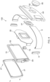
Figure 4 shows an exploded view of the belt shown inFigures 1A to 1D ; -
Figure 5 shows an isometric view of a third embodiment of the belt; -
Figure 6 shows a top view of the third embodiment of the belt as shown inFigure 5 ; -
Figure 7 shows a front view of the third embodiment of the belt as shown inFigure 5 ; -
Figure 8 shows a front view of the third embodiment of the belt as shown inFigure 5 ; -
Figure 9 shows an isometric view of a fourth embodiment of the belt; -
Figure 10 shows a top view of the fourth embodiment of the belt as shown inFigure 9 ; -
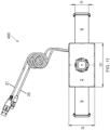
Figure 11 shows a front view of the fourth embodiment of the belt as shown inFigure 9 ; -
Figure 12 shows a side view of the fourth embodiment of the belt as shown inFigure 9 ; -
Figure 13 shows an isometric view of the fourth embodiment of the belt as shown inFigure 9 , with the charging cable retracted; -
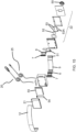
Figure 14 shows an exploded isometric view of the fourth embodiment of the belt as shown inFigure 9 ; -
Figure 15 shows a reverse exploded isometric view of the fourth embodiment of the device as shown inFigure 9 ; -
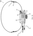
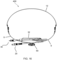
Figure 16 shows a top view of a fifth embodiment of the belt according to the present invention, with cable extended; -
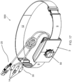
Figure 17 shows an isometric view of the embodiment of the belt as shown inFigure 16 ; -
Figure 18 shows a side view of the fifth embodiment of the belt as shown inFigure 16 ; and -
Figure 19 shows a front diagrammatic view of the fifth embodiment of the belt as shown inFigure 16 . - With reference to the Figures there are five
embodiments - In all embodiments there is provided a
buckle housing 2 that contains therechargeable battery 55. From thebuckle housing 2 extendbelt portions 9 that are adjusted in length by anadjustment mechanism 5. - All embodiments have at least one charging
cable battery 55 at aconnection point 56. The charging cable(s) 15, 20, 25, 35 is stored in (seeFigures 5 to 19 ) or around (seeFigures 1 ,2 and) thebuckle housing 2. - In the
embodiments Figures 1 to 4 the belt member is formed from twoparts clips 6. In this way thebelt 100 only passes part way around the wearer's waist, typically the front part of the wearer's waist. Alternatively, in some embodiments the length of the twoparts - In the
embodiments Figure 5 to 19 thebelt members buckle housing 2 are joined to asecond section 12 to form a continuous loop around a wearer. It is appreciated that the belt shown inembodiments second section 12, thereby connecting to the garment as described above, or by connection of ends of the twobelt portions - Preferably the
belt members second section 12 are not elastic, for example being cotton or Nylon (RTM) webbing. - The
battery 55 is contained within abuckle housing 2. - The
buckle housing 2 also houses anadjustment mechanism 5 which enables thebelt members - In the pictured embodiments the
adjustment mechanism 5 has areel 52 that is internally connected to proximal ends of thebelt members belt members buckle housing 2 to adjust their length. - In the pictured
embodiments Figures 5 to 19 the second section (connecting part) 12 is a fixed length and in use will be the opposing side of the user, passing around the wearer's back. - The
second section 12 and thebelt members belt members - The connecting parts of the attachment means 1 comprise mating clasps, 6,7, typically formed in stainless steel, although it is appreciated that other materials may be used.
- In this way the
second section 12 can be easily connected to thebelt members -
Figures 1A, 1B, 1C and 1D , and2A, 2B, 2C and 2D show first and second embodiments that vary only in size and in that thesecond embodiment 200 includes light emittingdiode indicators 11 to reflect charging status. Thefirst embodiment 100 is larger than thesecond embodiment 200. Preferred dimensions in millimetres are included to show examples of the buckle housing dimensions. - The
buckle housing 2 is rectangular and is curved to correspond to the curvature of a wearer's waist. Thebattery 55 is housed within thebuckle housing 2 and is connected to a printed circuit board (PCB) 54. The chargingcable 15 is connected to thebattery 55 via the PCB 54 (see the exploded view inFigure 3 ). - The
buckle housing 2 has afront face 22 andrear face 21 that encase aninternal wall 26 that is shaped and dimensioned to receive thebattery 55 on one face and theadjustment mechanism 5 on the opposed face. In this way theinternal wall 26 acts as a mount that is sandwiched between the front and rear faces of thehousing buckle housing 2 are joined by a set of four screws 27 (seeFigure 4 ). - Proximal ends of the
belt portions adjustment mechanism 5. - Distal ends of
belt portions clip 6 for connecting to either: a garment (forming a belt that passes part way around a user's waist); or to connect oneclip 6 to the other (forming a belt that passes completely around a wearer's waist); or to connect to acorresponding clip 7 on the second section 12 (to form a continuous belt around a wearer's waist). - In
Figures 1 and2 theadjustment mechanism 5 is a Fidlock Winch (RTM). Adial 50 is provided on the outer face of thefront face 22 of thehousing 2 which is turned or released to lengthen or shorten thebelt members - The
dial 50 is connected to thereel 52 to form a single part that connects in use to thebase 57. The single part (50, 52) connects to thebase 57 by a magnetic connection and there are separable to release thecord 53. There is an engagement means (not shown) between where thereel 52 andbase 57 engage. Both interfacing surfaces have corresponding teeth that engage so that thereel 52 can be turned in one direction to tighten thebelt portions single part base 57. - In
Figures 1B, 1C ,2B and 2C the chargingcable 15 is shown wrapped around a perimeter edge of thebuckle housing 2 when not in use. Acable holder 16 is provided to secure thecable 15 in place when not deployed for use. Thebuckle housing 2 has agroove 17 in which thecable 15 sits (seeFigures 1A and2A ). - It is appreciated that in an embodiment with a displaceable cable, the buckle housing may have no modifications to store a cable. For example the buckle housing may have a smooth exterior finish and the cable connected via the port (socket) when required.
- The cable is not shown in
Figures 1A, 1D ,2A and 2D . - In
Figures 5 to 18 thebuckle housing 2 has a compartment in which the cable(s) is received when not in use. - In
Figures 5 to 8 (third embodiment 300) thefront face 22 of thebuckle housing 2 has asocket 8 for receipt of a chargingcable 15. Thesocket 8 is covered by a displaceable tethered silicone plug to minimise any water or dust ingress in use. Therefore in this embodiment the chargingcable 15 is displaceable from thesocket 8. - In
Figures 5 to 8 thebuckle housing 2 contains oneextendable charging cable 15, which is provided on acable reel 3 situated a little way along thecable 15. This allows the wire remainder 4 (distal end of the cable 15) to be wound onto thecable reel 3. Thecable reel 3 may be a reel that is common in the art such as with a plastic casing covering the reel. - The charging
cable 15 has amagnetic end 13, which allows for a plug to be added and removed so that a plurality of different plugs can be provided on the one chargingcable 15. The different plug heads 14 are connected mechanically and electrically using a magnetic connection. It is appreciated that a mechanical connection without use a magnetic means may also be used. - With reference to the
fourth embodiment 400 shown inFigures 9 to 16 thisbuckle housing 2 has aninternal compartment 23 which is accessed through an opening that is closed by a slidingcover 24 in an upper side of thehousing 2. Thecover 24 comprises athumb slider depression 42 to aid with movement of thecover 24. - The
fourth embodiment 400 has two chargingcables cable 20 and a longoutgoing charge cable 25, which are both permanently connected to theinternal battery 55. Thecables compartment 23 when not in use. - On the
front face 22 of thehousing 2 there is adial 50 which provides the control means for theadjustment mechanism 5 and is used to retract the ends of thebelt members housing 2 during tightening to the second length. Thedial 50 connects to areel 52 and thedial 50 and reel 52 are received to abase 57. Thebase 57 and reel 52 are within thehousing 2 and thedial 50 extends from an outerfront face 22 of thehousing 2. - The
dial 50 has a plurality of external ridges to aid in purchase of a user's fingers against thedial 50. - Internally the proximal ends of the
belt members Figure 15 ) which receive acord 53 that engages with thereel 52 of theadjustment mechanism 5. - In other embodiments ends of the
belt members 9 may have a plurality of pins along their edges that engage with theadjustment mechanism 5 to enable incremental adjustment. - In the
fourth embodiments 400 shown inFigure 15 theadjustment mechanism 5 is a reel mechanism formed of adial 50,reel 52, andcord 53 which is wound around thereel 52 that engages with thedial 50. Each cord haspins 53A embedded in the cord for engagement with thereel 52,base 57 anddial 50. The embedded pins 53A enable accurate adjustment and to prevent slippage. - The
dial 50 is connected to thereel 52 such that the dial is turned to wind thecords 53 around thereel 52, which causes the proximal ends of thes belt members belt members - The pictured embodiments all internally include a
battery 55. In thefirst embodiment 100, second 200, andfourth embodiments 400 there is also shown a printedcircuit board 54. - The
PCB 54 may allow automated control of rotation of thereel 52 through aslider button 10, as is shown on both the third 300 and fourth 400 embodiments. Theslider button 10 provides an activation control for charging (acting as a switch to turn on and off charging), and a plurality of light emitting diodes 11 (LEDs) to indicate charge status, such as charging on/charging off/ level of charge etc. - With reference to the
fifth embodiment 500 as shown inFigures 16 to 19 the belt has two chargingcables cables 35 comprises multiple plug heads 14 for theoutgoing charge cable 35, so as to enable connection to a plurality of socket types for different electrical devices (not shown). - Both charging
cables buckle housing 2 and are accessed through an opening in the side edge. Thecables - The
housing 2 has a reduced depth relative to the third andfourth embodiments dial 50 extends further forward of the housing. - The Figures include some preferred dimensions of the
belt - The invention has been described by way of examples only and it will be appreciated that variation may be made to the above-mentioned embodiments without departing from the scope of protection as defined by the claims.
Claims (15)
- A belt with at least one rechargeable battery comprising: a buckle housing that contains the at least one rechargeable battery; wherein the buckle housing has an adjustment mechanism to adjust length of at least one belt member extending from the buckle housing and wherein the at least one rechargeable battery is connected to or connectable to a charging cable for connecting to an electrical device to be charged or for connection to a power supply to charge the rechargeable battery.
- A belt according to claim 1 including two belt members, one extending from each opposed end of the buckle housing; wherein distal ends of each belt member have an attachment means to connect to a garment, each other, or to a second section.
- A belt according to any preceding claim wherein the adjustment mechanism is a reel mechanism.
- A belt according to claim 3 wherein the reel mechanism has a reel that accepts a cord associated with the proximal ends of the belt member(s) and a dial connected to the reel that is turned to adjust length of the belt member(s).
- A belt according to claim 4 wherein the reel mechanism includes a base mounted on the buckle housing that receives the dial and reel as a single part and an engagement means between the single part and the base.
- A belt according to claim 5 wherein the engagement means is a ratchet mechanism to allow incremental adjustment.
- A belt according to any of claims 3 to 6 wherein the reel mechanism is a Fidlock Winch (RTM) mechanism.
- A belt according to any preceding claim wherein the at least one rechargeable battery has a port for receiving the charging cable.
- A belt according to any preceding claim wherein a distal end of the charging cable has a plurality of plugs for receiving different electrical devices.
- A belt according to any preceding claim wherein a distal end of the charging cable has a plug a for connection to a power supply to enable the rechargeable battery to be charged.
- A belt according to any preceding claim wherein the buckle housing provides a storage compartment for the charging cable(s).
- A belt according to any preceding claim comprising a cable wheel for the charging cable(s).
- A belt according to any preceding claim wherein at least part of the belt member is elastic.
- A belt according to any preceding claim including a second section for connection to the belt member(s) to form a continuous loop around the whole of a wearer's waist.
- A belt according to any preceding claim wherein the buckle housing has at least one indicator to display charging status and/or battery level.
Applications Claiming Priority (1)
| Application Number | Priority Date | Filing Date | Title |
|---|---|---|---|
| GBGB2313154.3A GB202313154D0 (en) | 2023-08-30 | 2023-08-30 | Engines |
Publications (1)
| Publication Number | Publication Date |
|---|---|
| EP4516146A1 true EP4516146A1 (en) | 2025-03-05 |
Family
ID=88237068
Family Applications (1)
| Application Number | Title | Priority Date | Filing Date |
|---|---|---|---|
| EP24193400.9A Pending EP4516146A1 (en) | 2023-08-30 | 2024-08-07 | A belt with a battery |
Country Status (3)
| Country | Link |
|---|---|
| US (1) | US12484642B2 (en) |
| EP (1) | EP4516146A1 (en) |
| GB (2) | GB202313154D0 (en) |
Families Citing this family (1)
| Publication number | Priority date | Publication date | Assignee | Title |
|---|---|---|---|---|
| US20260081410A1 (en) * | 2024-09-18 | 2026-03-19 | Joel Dennis | One-way retractable cable unit with magnetic center |
Citations (7)
| Publication number | Priority date | Publication date | Assignee | Title |
|---|---|---|---|---|
| JP2003306819A (en) * | 2002-04-12 | 2003-10-31 | Shokon Kyo | Belt housing battery |
| US20140304897A1 (en) * | 2013-04-10 | 2014-10-16 | Robert Acton | Touchdown Belt |
| WO2016056759A1 (en) | 2014-10-10 | 2016-04-14 | 김병건 | Multifunctional belt |
| WO2017000013A1 (en) * | 2015-06-30 | 2017-01-05 | Zipp It Gmbh | Closure system |
| CN211127168U (en) | 2019-09-20 | 2020-07-28 | 谢坚 | A belt-type large-capacity mobile power supply |
| CN213188287U (en) | 2020-08-13 | 2021-05-14 | 宁波凯信服饰股份有限公司 | Multifunctional leather belt |
| KR20220000040U (en) * | 2020-06-30 | 2022-01-06 | 김금숙 | Buckle with built-in rechargeable battery |
Family Cites Families (58)
| Publication number | Priority date | Publication date | Assignee | Title |
|---|---|---|---|---|
| US2304367A (en) * | 1940-10-05 | 1942-12-08 | Pittsburgh Garter Company | Safety battery belt |
| US3692253A (en) * | 1965-06-21 | 1972-09-19 | Borg Warner | Belt retractor and locking mechanism |
| US3913977A (en) * | 1973-02-16 | 1975-10-21 | Takata Kojyo Co | Automatic locking belt supported retractor |
| US3919615A (en) * | 1974-03-18 | 1975-11-11 | Ronald Niecke | Power belt |
| US5019767A (en) * | 1989-02-16 | 1991-05-28 | Nintendo Co., Ltd. | Portable power supply |
| US5211321A (en) * | 1991-11-25 | 1993-05-18 | Norton Rodriguez | Battery and equipment vest |
| US5592528A (en) * | 1994-11-14 | 1997-01-07 | Harris Corporation | Battery charging and signalling interconnect arrangement for craftsperson's |
| US5741306A (en) * | 1996-05-23 | 1998-04-21 | Lifecor, Inc. | Patient-worn energy delivery apparatus |
| US5713749A (en) * | 1996-09-26 | 1998-02-03 | Formosa Electronic Industries, Inc. | Multi-functional charging device |
| US6066211A (en) * | 1998-11-20 | 2000-05-23 | The Servicemaster Company | Battery-powered electric vacuum cleaner system |
| US6211649B1 (en) * | 1999-03-25 | 2001-04-03 | Sourcenext Corporation | USB cable and method for charging battery of external apparatus by using USB cable |
| US6573621B2 (en) * | 2000-12-01 | 2003-06-03 | S-B Power Tool Company | AC/DC power supply system for power tools |
| US6641433B2 (en) * | 2001-06-21 | 2003-11-04 | Brk Brands, Inc. | Universal wire harness for detectors |
| GB2382612B (en) * | 2001-11-30 | 2005-06-29 | John William Heffernan | Safety device |
| US20030121682A1 (en) * | 2001-12-28 | 2003-07-03 | Carrancho Tony M. | Independent electrical implement system |
| US7471060B2 (en) * | 2003-09-23 | 2008-12-30 | International Business Machines Corporation | Rechargeable electronic device system and method for recharging an electronic device |
| US7356934B2 (en) * | 2004-11-29 | 2008-04-15 | Wahl Clipper Corporation | Belt or clothing-mountable battery-powered hair clipper with holster |
| KR100819604B1 (en) * | 2005-07-27 | 2008-04-03 | 엘에스전선 주식회사 | Wireless Charger Decreased in Variation of Charging Efficiency |
| PL2436280T3 (en) * | 2006-07-12 | 2017-12-29 | Fidlock Gmbh | Mechanical-magnetic connection structure |
| US20080048612A1 (en) * | 2006-08-22 | 2008-02-28 | Sheng-I Yang | Wireless battery charger |
| US20090015198A1 (en) * | 2007-07-09 | 2009-01-15 | Marware, Inc. | Docking and charging station and method for a portable electronic device |
| US8484809B2 (en) * | 2007-07-17 | 2013-07-16 | Fidlock Gmbh | Mechanical/magnetic connecting structure |
| CN101951801B (en) * | 2008-02-21 | 2012-11-28 | 费得洛克有限公司 | Magnetomechanical connection assembly with load securing |
| US7804274B2 (en) * | 2008-07-21 | 2010-09-28 | Coulomb Technologies, Inc. | Vehicle charging station having a dual position locking door |
| US8212521B2 (en) * | 2009-01-05 | 2012-07-03 | Woncheol Choi | System and method for charging a mobile device |
| KR101587138B1 (en) * | 2009-08-27 | 2016-02-02 | 엘지전자 주식회사 | Mobile terminal |
| JP5427521B2 (en) * | 2009-09-04 | 2014-02-26 | 株式会社マキタ | Battery pack |
| US20110133695A1 (en) * | 2009-12-09 | 2011-06-09 | Richard Cadway | Power Tool Battery Cell Replacement Kit and Methods Thereof |
| JP2012054007A (en) * | 2010-08-31 | 2012-03-15 | Makita Corp | Battery device for power tool |
| TWM399483U (en) * | 2010-09-13 | 2011-03-01 | Powertech Ind Ltd | Electric receptacle with electric charging interface |
| US20120104999A1 (en) * | 2010-11-02 | 2012-05-03 | Triune Ip Llc | Multiple Coil System |
| DE102010044144B3 (en) * | 2010-11-18 | 2012-05-31 | Fidlock Gmbh | closure device |
| CN201946653U (en) * | 2011-02-01 | 2011-08-24 | 褚艳秋 | Core-exchangeable handset mobile supply |
| US8593108B2 (en) * | 2011-04-18 | 2013-11-26 | Rfa Brands, Llc | Portable charging system |
| US9130384B2 (en) * | 2011-10-06 | 2015-09-08 | Prong, Inc. | Smart phone and/or consumer electronics device charger system |
| EP3266338B1 (en) * | 2011-11-10 | 2019-03-20 | Think Tank Photo, Inc. | Backpack and waist bag carrying system |
| KR101196104B1 (en) * | 2012-01-30 | 2012-11-01 | 박태교 | adjustable belt |
| US9252612B2 (en) * | 2012-04-02 | 2016-02-02 | Mark Regan Baluha | Personal mobile charging device |
| US20140035747A1 (en) * | 2012-08-02 | 2014-02-06 | Sennco Solutions Inc. | Dongle, system, and/or method for securing an electronic device |
| CN202918004U (en) * | 2012-10-15 | 2013-05-01 | 东莞富强电子有限公司 | Wireless charger |
| TWI455391B (en) * | 2012-11-02 | 2014-10-01 | 緯創資通股份有限公司 | Charging device for portable mobile communication device |
| WO2014105973A1 (en) * | 2012-12-26 | 2014-07-03 | Micron Devices, LLC | Wearable antenna assembly |
| USD730278S1 (en) * | 2013-06-04 | 2015-05-26 | Enrico Licciardello, Jr. | Battery pack belt |
| US9559546B2 (en) * | 2013-10-01 | 2017-01-31 | Google Inc. | Stand inductive charger |
| US20160093417A1 (en) * | 2014-09-28 | 2016-03-31 | James Clifford Litterini | Mobile device cable strengthening and personalization device and method |
| US10359327B2 (en) * | 2014-12-01 | 2019-07-23 | Ebay Inc. | Waist measuring belt |
| US10050453B2 (en) * | 2015-03-19 | 2018-08-14 | Halo International SEZC Ltd. | Portable power adapter with detachable battery unit |
| USD738303S1 (en) * | 2015-04-07 | 2015-09-08 | Bluelounge Pte Ltd | Charging device |
| USD817268S1 (en) * | 2015-04-07 | 2018-05-08 | Advantus, Corp. | Charging device |
| US11452632B2 (en) * | 2017-05-12 | 2022-09-27 | Orthotic Solutions, Llc | Abdominal sacral waist support belt |
| CN207202275U (en) * | 2017-07-10 | 2018-04-10 | 雷立军 | A kind of Multifunctional belt button and its belt |
| CN208480693U (en) * | 2018-05-29 | 2019-02-12 | 湖北魔牛电子科技有限公司 | A kind of emergent charging belt buckle |
| CN111317225B (en) * | 2020-02-28 | 2022-05-13 | 维沃移动通信有限公司 | Wearable device |
| CN214154041U (en) * | 2020-07-28 | 2021-09-07 | 郑联达 | Belt charger baby |
| USD1009401S1 (en) * | 2021-05-28 | 2023-12-26 | FIDLOCK, GmbH | Winch |
| USD1008602S1 (en) * | 2021-07-19 | 2023-12-19 | Fidlock Gmbh | Winch base |
| USD1000934S1 (en) * | 2021-07-21 | 2023-10-10 | Fidlock Gmbh | Winch |
| CN217041122U (en) * | 2022-03-17 | 2022-07-26 | 广东朗固实业有限公司 | Fire-entry suit convenient to dress fast |
-
2023
- 2023-08-30 GB GBGB2313154.3A patent/GB202313154D0/en not_active Ceased
-
2024
- 2024-08-07 GB GB2411636.0A patent/GB2636247A/en active Pending
- 2024-08-07 US US18/796,808 patent/US12484642B2/en active Active
- 2024-08-07 EP EP24193400.9A patent/EP4516146A1/en active Pending
Patent Citations (7)
| Publication number | Priority date | Publication date | Assignee | Title |
|---|---|---|---|---|
| JP2003306819A (en) * | 2002-04-12 | 2003-10-31 | Shokon Kyo | Belt housing battery |
| US20140304897A1 (en) * | 2013-04-10 | 2014-10-16 | Robert Acton | Touchdown Belt |
| WO2016056759A1 (en) | 2014-10-10 | 2016-04-14 | 김병건 | Multifunctional belt |
| WO2017000013A1 (en) * | 2015-06-30 | 2017-01-05 | Zipp It Gmbh | Closure system |
| CN211127168U (en) | 2019-09-20 | 2020-07-28 | 谢坚 | A belt-type large-capacity mobile power supply |
| KR20220000040U (en) * | 2020-06-30 | 2022-01-06 | 김금숙 | Buckle with built-in rechargeable battery |
| CN213188287U (en) | 2020-08-13 | 2021-05-14 | 宁波凯信服饰股份有限公司 | Multifunctional leather belt |
Also Published As
| Publication number | Publication date |
|---|---|
| GB202411636D0 (en) | 2024-09-18 |
| GB202313154D0 (en) | 2023-10-11 |
| GB2636247A (en) | 2025-06-11 |
| US12484642B2 (en) | 2025-12-02 |
| US20250072529A1 (en) | 2025-03-06 |
Similar Documents
| Publication | Publication Date | Title |
|---|---|---|
| US10707694B2 (en) | Portable power charger with power input and power output connection interfaces | |
| US5923146A (en) | Battery charging unit incorporated in a power cord reel housing | |
| US8624554B2 (en) | Solar bracelet | |
| US9072363B2 (en) | Retractor carrying case | |
| US8410748B2 (en) | Removable photovoltaic charging pack including a device compartment and container including a receiving compartment with a transparent panel to hold the charging pack | |
| US9016531B2 (en) | Retractor carrying case | |
| US9179762B2 (en) | Phone retractor carrying case | |
| US9505547B2 (en) | Attachable extendable and retractable earpiece and protective casing assembly for mobile communication and sound devices | |
| US20070278265A1 (en) | System for carrying portable device | |
| US12484642B2 (en) | Belt with a battery | |
| US20150341071A1 (en) | Carrying case for mobile phones | |
| US20060121962A1 (en) | Carrying case for a mobile telephone with cord organization means | |
| US10763908B2 (en) | Mobile phone with enhanced functions | |
| US20150341067A1 (en) | Carrying case for mobile phones | |
| US20190305569A1 (en) | Decorative portable power charger | |
| CA2989848A1 (en) | Phone carrier | |
| CN209788729U (en) | Alpenstock | |
| CN221446393U (en) | Intelligent glasses | |
| CN223514615U (en) | Helmet charging equipment | |
| CN114811462A (en) | Chest hanging lamp | |
| JP2004013004A (en) | camera | |
| JPH11345501A (en) | Portable light | |
| EP0565322A1 (en) | Battery pack |
Legal Events
| Date | Code | Title | Description |
|---|---|---|---|
| PUAI | Public reference made under article 153(3) epc to a published international application that has entered the european phase |
Free format text: ORIGINAL CODE: 0009012 |
|
| STAA | Information on the status of an ep patent application or granted ep patent |
Free format text: STATUS: THE APPLICATION HAS BEEN PUBLISHED |
|
| AK | Designated contracting states |
Kind code of ref document: A1 Designated state(s): AL AT BE BG CH CY CZ DE DK EE ES FI FR GB GR HR HU IE IS IT LI LT LU LV MC ME MK MT NL NO PL PT RO RS SE SI SK SM TR |
|
| STAA | Information on the status of an ep patent application or granted ep patent |
Free format text: STATUS: REQUEST FOR EXAMINATION WAS MADE |
|
| 17P | Request for examination filed |
Effective date: 20250806 |
|
| STAA | Information on the status of an ep patent application or granted ep patent |
Free format text: STATUS: EXAMINATION IS IN PROGRESS |
|
| 17Q | First examination report despatched |
Effective date: 20251114 |