EP4516142A2 - Aerosol generation apparatus - Google Patents
Aerosol generation apparatus Download PDFInfo
- Publication number
- EP4516142A2 EP4516142A2 EP24193177.3A EP24193177A EP4516142A2 EP 4516142 A2 EP4516142 A2 EP 4516142A2 EP 24193177 A EP24193177 A EP 24193177A EP 4516142 A2 EP4516142 A2 EP 4516142A2
- Authority
- EP
- European Patent Office
- Prior art keywords
- power supply
- atomizer
- circuit
- identity
- generation apparatus
- Prior art date
- Legal status (The legal status is an assumption and is not a legal conclusion. Google has not performed a legal analysis and makes no representation as to the accuracy of the status listed.)
- Pending
Links
Images






Classifications
-
- A—HUMAN NECESSITIES
- A24—TOBACCO; CIGARS; CIGARETTES; SIMULATED SMOKING DEVICES; SMOKERS' REQUISITES
- A24F—SMOKERS' REQUISITES; MATCH BOXES; SIMULATED SMOKING DEVICES
- A24F40/00—Electrically operated smoking devices; Component parts thereof; Manufacture thereof; Maintenance or testing thereof; Charging means specially adapted therefor
- A24F40/40—Constructional details, e.g. connection of cartridges and battery parts
-
- A—HUMAN NECESSITIES
- A24—TOBACCO; CIGARS; CIGARETTES; SIMULATED SMOKING DEVICES; SMOKERS' REQUISITES
- A24F—SMOKERS' REQUISITES; MATCH BOXES; SIMULATED SMOKING DEVICES
- A24F40/00—Electrically operated smoking devices; Component parts thereof; Manufacture thereof; Maintenance or testing thereof; Charging means specially adapted therefor
- A24F40/30—Devices using two or more structurally separated inhalable precursors, e.g. using two liquid precursors in two cartridges
-
- A—HUMAN NECESSITIES
- A24—TOBACCO; CIGARS; CIGARETTES; SIMULATED SMOKING DEVICES; SMOKERS' REQUISITES
- A24F—SMOKERS' REQUISITES; MATCH BOXES; SIMULATED SMOKING DEVICES
- A24F40/00—Electrically operated smoking devices; Component parts thereof; Manufacture thereof; Maintenance or testing thereof; Charging means specially adapted therefor
- A24F40/40—Constructional details, e.g. connection of cartridges and battery parts
- A24F40/42—Cartridges or containers for inhalable precursors
-
- A—HUMAN NECESSITIES
- A24—TOBACCO; CIGARS; CIGARETTES; SIMULATED SMOKING DEVICES; SMOKERS' REQUISITES
- A24F—SMOKERS' REQUISITES; MATCH BOXES; SIMULATED SMOKING DEVICES
- A24F40/00—Electrically operated smoking devices; Component parts thereof; Manufacture thereof; Maintenance or testing thereof; Charging means specially adapted therefor
- A24F40/40—Constructional details, e.g. connection of cartridges and battery parts
- A24F40/46—Shape or structure of electric heating means
-
- A—HUMAN NECESSITIES
- A24—TOBACCO; CIGARS; CIGARETTES; SIMULATED SMOKING DEVICES; SMOKERS' REQUISITES
- A24F—SMOKERS' REQUISITES; MATCH BOXES; SIMULATED SMOKING DEVICES
- A24F40/00—Electrically operated smoking devices; Component parts thereof; Manufacture thereof; Maintenance or testing thereof; Charging means specially adapted therefor
- A24F40/40—Constructional details, e.g. connection of cartridges and battery parts
- A24F40/48—Fluid transfer means, e.g. pumps
-
- A—HUMAN NECESSITIES
- A24—TOBACCO; CIGARS; CIGARETTES; SIMULATED SMOKING DEVICES; SMOKERS' REQUISITES
- A24F—SMOKERS' REQUISITES; MATCH BOXES; SIMULATED SMOKING DEVICES
- A24F40/00—Electrically operated smoking devices; Component parts thereof; Manufacture thereof; Maintenance or testing thereof; Charging means specially adapted therefor
- A24F40/50—Control or monitoring
-
- A—HUMAN NECESSITIES
- A24—TOBACCO; CIGARS; CIGARETTES; SIMULATED SMOKING DEVICES; SMOKERS' REQUISITES
- A24F—SMOKERS' REQUISITES; MATCH BOXES; SIMULATED SMOKING DEVICES
- A24F40/00—Electrically operated smoking devices; Component parts thereof; Manufacture thereof; Maintenance or testing thereof; Charging means specially adapted therefor
- A24F40/50—Control or monitoring
- A24F40/53—Monitoring, e.g. fault detection
-
- A—HUMAN NECESSITIES
- A24—TOBACCO; CIGARS; CIGARETTES; SIMULATED SMOKING DEVICES; SMOKERS' REQUISITES
- A24F—SMOKERS' REQUISITES; MATCH BOXES; SIMULATED SMOKING DEVICES
- A24F40/00—Electrically operated smoking devices; Component parts thereof; Manufacture thereof; Maintenance or testing thereof; Charging means specially adapted therefor
- A24F40/10—Devices using liquid inhalable precursors
-
- A—HUMAN NECESSITIES
- A24—TOBACCO; CIGARS; CIGARETTES; SIMULATED SMOKING DEVICES; SMOKERS' REQUISITES
- A24F—SMOKERS' REQUISITES; MATCH BOXES; SIMULATED SMOKING DEVICES
- A24F40/00—Electrically operated smoking devices; Component parts thereof; Manufacture thereof; Maintenance or testing thereof; Charging means specially adapted therefor
- A24F40/40—Constructional details, e.g. connection of cartridges and battery parts
- A24F40/48—Fluid transfer means, e.g. pumps
- A24F40/485—Valves; Apertures
Definitions
- the usage parameter includes a cumulative time used or a remaining time available of the atomizer; or the usage parameter includes a quantity of cumulative puffs taken or a quantity of remaining puffs available of the atomizer.
- the power supply assembly includes a power supply and a circuit board, a power supply module is arranged on the circuit board, and the power supply assembly is configured to output the power to the atomizer through the power supply module.
- the conductive member is configured to establish a conductive path between the power supply module selectively connected to the conductive member and the corresponding atomizer, so that the atomizer is in a standby state or an operating state.
- At least two electrodes in the second electrode set in the power supply module are connected to each other.
- the identification circuit and the identity circuit are both arranged on the circuit board.
- an anode terminal and a cathode terminal are arranged on the circuit board, a plurality of power supply modules are connected in parallel between the anode terminal and the cathode terminal, and the power supply is configured to supply the power to the circuit board through the anode terminal and the cathode terminal.
- the identification circuit includes a controller and a sampling resistor, each of the identity circuits is connected in series or in parallel with the sampling resistor, and the controller is configured to obtain a first electrical parameter of the sampling resistor and identify the identity information of the identity circuit based on the first electrical parameter.
- a process, a method, a system, a product, or a device that includes a series of steps or units is not limited to the listed steps or units, and instead, further optionally includes a step or unit that is not listed, or further optionally includes another step or unit that is intrinsic to the process, the method, the product, or the device.
- Embodiments mentioned in the specification mean that particular features, structures, or characteristics described with reference to the embodiments may be included in at least one embodiment of this application.
- the phrase appearing at various locations in this specification does not necessarily indicate a same embodiment, and is not an independent or alternative embodiment exclusive to another embodiment.
- an embodiment of this application provides an aerosol generation apparatus.
- the aerosol generation apparatus includes a conductive member 1, a power supply assembly 3, and an atomization assembly 2 having a plurality of atomizers 21.
- the conductive member 1 can be driven, so that the conductive member 1 can change a position. Therefore, the conductive member 1 can be configured to select the atomizer 21 electrically connected to the power supply assembly 3, so that the power supply assembly 3 can supply power to the atomizer 21 selected by the conductive member 1, and the selected atomizer 21 can generate an aerosol.
- the "electrical connection” and the “electrical conduction” described in this application are two different concepts.
- the “electrical connection” means that a conductive line between two elements is connected, with a premise that a current flows from one element to the other element.
- the “electrical conduction” means that a current is flowing from one element to the other element.
- the atomization assembly 2 includes a plurality of atomizers 21 independently of each other. Each atomizer 21 is configured to operate independently when obtaining the power.
- the atomizer 21 may be provided with a storage cavity 211 that can accommodate a liquid substrate.
- the liquid substrate stored in each atomizer 21 may not exceed 5 ml, for example, may be approximately 2 ml.
- the liquid substrate may include a liquid containing a tobacco substance containing a volatile tobacco flavor ingredient, and may further be a liquid containing a non-tobacco substance.
- the liquid substrate may include water, a medicinal liquid, a solvent, ethanol, a plant extract, a perfume, a flavoring agent, or a vitamin mixture.
- the perfume may include a betel nut extracting solution, menthol, peppermint, spearmint oil, various fruity aroma ingredients, and the like, but is not limited thereto.
- the flavoring agent may include ingredients that may provide various aromas or flavors to a user.
- the vitamin mixture may be a mixture mixed with at least one of a vitamin A, a vitamin B, a vitamin C, and a vitamin E, but is not limited thereto.
- the aerosol generation apparatus may be used in different fields, for example, medical treatment and electronic aerosol atomization.
- the "plurality of” refers to two or more.
- 4 atomizers 21 are arranged, but is not limited thereto.
- At least two atomizers 21 of the plurality of atomizers 21 may be configured to accommodate different liquid substrates.
- Different liquid substrates include liquid substrates with different flavors or liquid substrates with different ingredients and proportions, so that different sensory experiences may be provided to the user by switching the atomizers 21.
- all of the atomizers 21 may contain the same liquid substrate.
- Each atomizer 21 may further have an atomization core 212.
- the atomization core 212 is in fluid communication with the storage cavity 211.
- the atomization core 212 is configured to atomize the liquid substrate, so that the liquid substrate generates an aerosol.
- the atomization core 212 may include a liquid absorbing element and a heating element.
- the liquid absorbing element may be a porous body or fiber, which can absorb the liquid substrate and guide the liquid substrate into an atomization range of the heating element.
- the heating element is configured to atomize at least part of the liquid substrate on the liquid absorbing element to form an aerosol.
- the heating element may be integrated on the liquid absorbing element, so that the heating element and the liquid absorbing element can form a whole.
- Each atomizer 21 may further have an air supply channel 213.
- the air supply channel 213 provides at least part of an airflow channel in fluid communication with the atomization core 212 and a suction nozzle assembly 4.
- the aerosol generated through atomization of the atomization core 212 enters the suction nozzle assembly 4 through the airflow channel.
- the storage cavity 211 may be arranged around the air supply channel 213, or the air supply channel 213 may be arranged on a side of the storage cavity 211.
- At least part of the suction nozzle assembly 4 may be held in a mouth of the user. The user inhales the aerosol through inhaling the suction nozzle assembly.
- an atomization compartment in fluid communication with the storage cavity 211 may be arranged in the atomizer 21.
- the atomization core 212 is accommodated in the atomization compartment.
- the air supply channel 213 is in fluid communication with the atomization compartment.
- the storage cavity 211 is located between the suction nozzle assembly 4 and the atomization compartment.
- the suction nozzle assembly 4 is located above the storage cavity 211, and the atomization compartment is located below the storage cavity 211.
- FIG. 3 At least part of the atomization core 212 is arranged in the air supply channel 213.
- a liquid guide hole is provided on the air supply channel 213.
- the atomization core 212 is in fluid communication with the storage cavity 211 through the liquid guide hole.
- the liquid substrate in the storage cavity 211 may pass through the liquid guide hole to be absorbed by the liquid absorbing element and atomized by the heating element, or a part of the liquid absorbing element may pass through the liquid guide hole into the storage cavity 211 to absorb and transfer the liquid substrate.
- each atomizer 21 may further include a first flexible member 214 having a first air channel 2141.
- the first flexible member 214 is arranged adjacent to the suction nozzle assembly 4, and the first air channel 2141 is in fluid communication with the atomization core 212 in the atomizer 21.
- the first air channel 2141 provides at least part of the airflow channel that communicates the atomization core 212 with the suction nozzle assembly 4, and the first flexible member 214 may seal an upper end of the corresponding storage cavity 211.
- the first air channel 2141 is in fluid communication with the air supply channel 213, the first air channel 2141 is in fluid communication with the atomization core 212 through the air supply channel 213, and an upper end of the air supply channel 213 is fixed through the first flexible member 214.
- the upper end of the air supply channel 213 is in communication with the first air channel 2141 while being embedded in the first flexible member 214 and fixed therein.
- each atomizer 21 may further include a second flexible member 215 having a second air channel 2151.
- the second flexible member 215 is arranged at an end opposite to the first flexible member 214.
- the second flexible member 215 may seal a lower end of the corresponding storage cavity 211.
- the storage cavity 211 is located between the first flexible member 214 and the second flexible member 215.
- the second air channel 2151 is in fluid communication with the atomization core 212 in the atomizer 21. Air outside the atomizer 21 may enter the air supply channel 213 through the second air channel 2151. Volatiles formed by atomizing the liquid substrate by the atomization core 212 are combined with the air entering from the second air channel 2151 to form an aerosol.
- the power supply assembly 3 includes a power supply 31 and a circuit board 32.
- the power supply 31 may include any suitable battery.
- the battery may be a rechargeable battery, or the battery may be a disposable battery.
- the battery is a lithium-ion battery.
- the battery may be a nickel metal hydride battery, a nickelcadmium battery, or a lithium-based battery, for example, a lithium cobalt battery, a lithium iron phosphate battery, a lithium titanate battery, or a lithium polymer battery.
- One or more control circuits are arranged on the circuit board 32.
- the control circuit may control power outputted by the battery.
- the battery is enabled to output an alternating current, a direct current, or the like.
- the battery is enabled to output a current or a voltage in the form of a pulse.
- a plurality of power supply modules 321 are arranged on the circuit board 32, and the power supply assembly 3 supplies power to a corresponding atomizer 21 through the power supply modules 321.
- a quantity of power supply modules 321 is less than a quantity of atomizers 21. Therefore, the atomizers 21 and the power supply modules 321 may be moved or rotated relative to each other, to enable the power supply modules 321 to switch the atomizers 21 electrically connected thereto.
- the quantity of power supply modules 321 may be greater than the quantity of atomizers 21.
- a plurality of power supply modules 321 may be arranged, and a quantity of power supply modules 321 is equal to the quantity of atomizers 21. Therefore, the plurality of power supply modules 321 and the plurality of atomizers may be electrically connected in a one-to-one manner or associated in a one-to-one manner.
- Each atomizer 21 may be electrically connected to different power supply modules 321.
- the plurality of atomizers 21 are electrically connected to the plurality of power supply modules in one-to-one correspondence.
- the atomizer 21 is configured to be non-switchable with the power supply module 321 electrically connected thereto.
- the aerosol generation apparatus is configured such that all of the atomizers 21 cannot simultaneously operate to generate the aerosol, and only some of the atomizers 21 can obtain power from the power supply modules 321 associated therewith and generate the aerosol at the same moment.
- switching elements 321 in one-to-one correspondence with the plurality of power supply modules are arranged.
- the user may control a selected switching element by inputting an instruction, so that the power supply module 321 corresponding to the switching element can supply power to the corresponding atomizer 21, and the corresponding atomizer 21 can obtain the power to start the operation and enter a standby state or an operating state.
- the "standby state" of the atomizer described in this application means that as long as the power supply supplies power to the power supply module, the power supply module may supply power to the corresponding atomizer.
- the atomizer in the standby state needs to wait for a further instruction.
- the further instruction is configured for allowing the power supply to supply power to the corresponding atomizer through the power supply module. After the further instruction is obtained, the atomizer may enter the operating state.
- the further instruction may be a smoking action of the user, or the like.
- the user may input a start instruction through an instruction input member (the instruction input member includes, but is not limited to, a smoking detector, a key switch, a sliding switch, a touch switch, an inductive switch, a remote switch, a touch screen, or the like).
- the power supply assembly electrically connects the power supply to the corresponding power supply module based on the start instruction, and therefore the power supply assembly can supply power to the corresponding atomizer through the power supply module, so that the atomizer is in the operating state and generates the aerosol.
- the "operating state" of the atomizer described in this application means that the power supply has already supplied power to the corresponding atomizer through the power supply module, and the atomizer is in a state of generating the aerosol by using the power.
- each power supply module 321 includes a first electrode set 322 and a second electrode set 323.
- the plurality of atomizers 21 are electrically connected to different first electrode sets 322.
- the power supply module 321 is configured to output power to the atomizer 21 associated therewith through the first electrode set 322 included therein.
- the first electrode set 322 and the second electrode set 323 in the same power supply module 321 are associated with each other.
- an electrical connection between electrodes in the second electrode set 323, a magnitude of an impedance of a line between electrodes in the second electrode set 323, or the like determines whether a line between the first electrode set 322 associated therewith and the power supply 31 is cut off, or determines whether the power supply 31 can output the power through the first electrode set 322 associated with the second electrode set 323.
- the line between the power supply 31 and the first electrode set 322 associated with the second electrode set 323 is therefore cut off. Accordingly, the power supply 31 cannot supply power to the first electrode set 322, and cannot output power to the corresponding atomization assembly 2 through the first electrode set 322.
- the plurality of atomizers 21 are electrically connected to a plurality of first electrode sets 322 in one-to-one correspondence.
- the power supply assembly 3 outputs the power through one of the first electrode sets 322
- the atomizer 21 electrically connected to the first electrode set 322 may obtain power from the first electrode set 322, so that the atomizer 21 starts operating and enters the operating state.
- the heating element in the atomizer 21 can atomize the liquid substrate, and then the atomizer 21 may generate the aerosol.
- Each atomizer 21 may include a third electrode set 216.
- a quantity of electrodes in the third electrode set 216 may be equal to a quantity of electrodes in the first electrode set 322 electrically connected to the atomizer 21.
- the electrodes in the third electrode set 216 may be connected in one-to-one correspondence with the electrodes in the first electrode set 322 electrically connected to the atomizer 21.
- the connection may be a separable connection, for example, may be elastic abutment, or the connection may be an inseparable connection, for example, welding.
- each atomizer 21 further includes a lead connected to the heating element. The lead extends out of the atomizer 21, and then is electrically connected to the first electrode set 322 corresponding to the atomizer.
- the atomization assembly 2 is connected to the circuit board 32, so that the atomization assembly 2 and the circuit board 32 cannot rotate relative to each other.
- the atomization assembly 2 includes a first support 22.
- the plurality of atomizers 21 are fixed to the first support 22, so that the plurality of atomizers 21 simultaneously remain stationary with respect to the first support 22.
- the power supply assembly 3 includes a second support 33.
- the circuit board 32 may be integrated on the second support 33, so that the circuit board 32 may remain stationary with respect to the second support 33.
- an anti-rotation member 34 extending to be inserted into the atomization assembly 2 is arranged on the second support 33, or an anti-rotation member extending to be inserted into the power supply assembly 3 is arranged on the first support 22, or the first support 22 and the second support 33 are integrally formed. Therefore, the first support 22 and the second support 33 cannot rotate relative to each other, so that the atomizer 21 and the circuit board 32 cannot rotate relative to each other.
- the anti-rotation member 34 may extend through the circuit board 32.
- the anti-rotation member 34 has a third air channel 341.
- the anti-rotation member 34 extends from the second support 33, and an end thereof is inserted into the second flexible member 215 of the atomizer 21 correspondingly arranged thereto.
- the third air channel 341 in the anti-rotation member 34 is in fluid communication with the second air channel 2151 in the second flexible member 215, and air enters the second air channel 2151 through the third air channel 341, and then enters the air supply channel 213.
- a plurality of anti-rotation members 34 having the third air channel 341 may be arranged. At least two anti-rotation members 34 are respectively inserted into two different atomizers 21, so that the third air channels 341 in the different anti-rotation members 34 are respectively in fluid communication with different air supply channels 213.
- the threaded connector 5 may be threadably connected to both a first connector 22 and a second connector 33.
- the threaded connector 5 may be connected to a center of the first support 22 and a center of the second support 33.
- the anti-rotation member 34 shown in the foregoing embodiment may be arranged on the second support 33, and the threaded connector 5 may extend through the anti-rotation member 34.
- the threaded connector 5 may be spaced apart from the atomizer 21.
- a first positioning mechanism 11 may be arranged on the conductive member 1, and a second positioning mechanism 35 may be arranged on the first support 22 or the second support 33.
- the first positioning mechanism 11 and the second positioning mechanism 35 are interlocked to prevent the conductive member 1 from continuing to rotate relative to the first support 22 and/or the second support 33, so as to ensure that the conductive member 1 maintains a stable electrical connection with the corresponding second electrode set 323, and ensure that the power supply 31 can stably supply power to the first electrode set 322 associated with the second electrode set.
- the aerosol generation apparatus further includes a connector 12.
- the conductive member 1 is held on the connector 12, and the conductive member 1 can synchronously rotate with the connector 12.
- a first accommodation cavity 14 is formed inside the connector 12. At least part of the atomization assembly 2 is accommodated in the first accommodation cavity 14, and the atomization assembly 2 accommodated in the first accommodation cavity 14 cannot rotate relative to the circuit board 32 in the first accommodation cavity 14.
- the suction nozzle assembly 4 is configured to rotate relative to the atomization assembly 2.
- the atomizer 21 in fluid communication with the suction nozzle assembly 4 can be switched. Therefore, the air supply channels 213 of different atomizers 21 may be in fluid communication with the suction nozzle assembly 4 through rotation.
- the suction nozzle assembly 4 includes an air channel tube 41.
- a first end of the air channel tube 41 is in a mouth of the user, and a second end opposite to the first end is arranged in a direction of the atomization assembly 2.
- a separator 121 is arranged on the aerosol generation apparatus. The separator 121 extends along a radial direction of the atomization assembly 1, and the separator 121 is located between the air channel tube 41 and the atomization assembly 2. A part of the separator 121 is open, so that at least one atomizer 21 of the plurality of atomizers 21 can be in fluid communication with the air channel tube 41. Meanwhile, the separator 121 can simultaneously block an airflow channel between one or more of the remaining atomizers 21 and the air channel tube 41.
- the first air channel 2141 on the first flexible member 214 of one of the atomizers 21 is not blocked by the separator 121. Therefore, the atomizer 21 is in fluid communication with the suction nozzle assembly 4.
- the aerosol generated by the atomizer 21 can be transferred to the air channel tube 41 through the airflow channel, and then smoked into a mouth by the user.
- the first flexible members 214 of the remaining atomizers 21 all elastically abut against the separator 121, so that the first air channels 2141 of the first flexible members 214 on the atomizers 21 are sealed or blocked by the separator 121. Therefore, at the same time, only one atomizer 21 of the plurality of atomizers 21 may be enabled to be in fluid communication with the suction nozzle assembly 4, and the remaining atomizers 21 are in an enclosed state.
- the suction nozzle assembly 4 is configured to be statically connected to the connector 12, so that the conductive member 1 can rotate together with the suction nozzle assembly 4 relative to the circuit board 32 and the atomization assembly 2. Therefore, while rotating the suction nozzle assembly 4 and enabling the suction nozzle assembly 4 to select the atomizer 21 in fluid communication with the suction nozzle assembly, the conductive member 1 may be enabled to select the second electrode set 323 abutting against the conductive member, and vice versa.
- the atomizer 21 corresponding to the second electrode set 323 abutting against the conductive member 1 and the atomizer 21 in fluid communication with the suction nozzle assembly 4 are the same atomizer 21. Therefore, a rotation operation may cause the atomizer 21 to be in the operating state when the first electrode set 322 associated with the second electrode set 323 supplies power to the corresponding atomizer 21.
- the aerosol generated by the atomizer 21 can be guided into the suction nozzle assembly 4 through the airflow channel, and finally smoked into the mouth by the user.
- the conductive member 1 When the suction nozzle assembly 4 is statically connected to the conductive member 1, the conductive member 1 may be driven to rotate relative to the atomization assembly 2 and the circuit board 32 by driving the suction nozzle assembly 4 to rotate. Alternatively, the suction nozzle assembly 4 may be driven to rotate relative to the atomization assembly 2 by driving the conductive member 1 to rotate.
- the conductive member 1 may be made of a conductive material.
- the conductive member 1 abuts against the second electrode set 323.
- the connector 12 is connected to the conductive member 1 and the suction nozzle assembly 4.
- the body 132 may be constructed as an arc.
- the arc is in a curved but not closed shape.
- the abutting pin 131 extends toward an inner side of the arc. It should be noted that the body 132 may further be in another shape.
- a quantity of abutting pins 131 may be equal to a quantity of electrodes in the second electrode set 323.
- Each abutting pin 131 may abut against each electrode in the second electrode set 323 in one-to-one correspondence.
- two abutting pins 131 are arranged.
- two electrodes are also arranged in the second electrode set 323.
- three abutting pins 131 are arranged.
- three electrodes are also arranged in the second electrode set 323.
- the abutment between the abutting pin 131 and the power supply module 321 may be elastic abutment, to ensure that the electrical connection between the conductive member 1 and the corresponding power supply module 321 is stable.
- the electrodes in the abutting pin 131 and/or the second electrode set 323 are elastic.
- the abutting pin 131 may include an elastic piece and a contact arranged on the elastic piece for abutting against the power supply module.
- An interior of the connector 12 may be provided with the first accommodation cavity 14 for accommodating at least part of the atomization assembly.
- the first accommodation cavity 14 may be arranged between the suction nozzle assembly 4 and the circuit board 32.
- the interior of the connector 12 may be provided with a second accommodation cavity 15. At least part of the suction nozzle assembly 4 may be accommodated in the second accommodation cavity 15, and the suction nozzle assembly 4 is configured to be unable to rotate in the second accommodation cavity 15.
- a part of the connector 12 forms the separator 121 described in any of the foregoing embodiments.
- the separator 121 defines at least part of a boundary of a bottom of the second accommodation cavity 15.
- the aerosol generation apparatus further includes a rotating member 16. At least part of the rotating member 16 may extend into an interior of the atomization assembly 2.
- the rotating member 6 is configured to rotate relative to the atomization assembly 2.
- the suction nozzle assembly 4 and the conductive member 1 are both statically connected to the rotating member 6, so that the suction nozzle assembly 4 and the conductive member 1 also rotate relative to the atomization assembly 2 when the rotating member 6 rotates relative to the atomization assembly 2.
- the rotating member 6 may be driven to rotate by driving the suction nozzle assembly 4 to rotate, and then the conductive member 1 is driven to rotate through the rotation of the rotating member 6.
- the rotating member 6 may be driven to rotate by driving the conductive member 1 to rotate, and then the suction nozzle assembly 4 is driven to rotate through the rotation of the rotating member 6.
- the atomization assembly 2 is arranged around the rotating member 6.
- the conductive member 1 can rotate together with the suction nozzle assembly 4 relative to the circuit board 32 and the atomization assembly 2. Therefore, while rotating the suction nozzle assembly 4 and enabling the suction nozzle assembly 4 to select the atomizer 21 in fluid communication with the suction nozzle assembly, the conductive member 1 may be enabled to select the second electrode set 323 abutting against the conductive member, and vice versa.
- an end of the rotating member 6 is statically connected to the suction nozzle assembly 4, an other end of the rotating member 6 extends through the atomization assembly 2 and is rotatably connected to the power supply assembly 3, and the conductive member 1 is arranged on a periphery of the rotating member 6.
- rotating member 6 is optional rather than mandatory.
- an inner side of the atomization assembly 2 is not provided with a rotating member that may rotate with the suction nozzle assembly 4.
- the suction nozzle assembly 4 is configured to be simultaneously in fluid communication with the air supply channels of the plurality of atomizers 21.
- the suction nozzle assembly 4 is configured to be able to rotate relative to the atomization assembly 2. However, during the rotation of the suction nozzle assembly 4 relative to the atomization assembly 2, the suction nozzle assembly being simultaneously in fluid communication with the air supply channels of the plurality of atomizers 21 is not affected.
- the conductive member 1 may be statically connected to the suction nozzle assembly 4, so that the conductive member 1 can rotate together with the suction nozzle assembly 4 relative to the atomization assembly 2.
- the rotation of the conductive member 1 relative to the atomization assembly 2 and the rotation of the suction nozzle assembly 4 relative to the atomization assembly 2 are independent and unrelated. There may be no connection or transmission relationship between the suction nozzle assembly 4 and the conductive member 1.
- the suction nozzle assembly 4 is configured to be unable to rotate relative to the atomization assembly 2 and the circuit board 32.
- the aerosol generation apparatus further includes a smoking detector 7 for detecting whether the aerosol generation apparatus is smoked.
- the smoking detector 7 is connected to a circuit board 32.
- the circuit board 32 is configured to control a power supply 31 to output power to a corresponding atomizer 21 through a power supply module 321 against which a conductive member 1 abuts when the smoking detector 7 detects that the aerosol generation apparatus is smoked, so that the atomizer generates an aerosol.
- the aerosol generation apparatus has an air intake channel inside.
- the air intake channel is in fluid communication with air outside the aerosol generation apparatus and an air supply channel of the atomizer 21.
- the air outside the aerosol generation apparatus enters the air supply channel 213 through the air intake channel, and an air flow rate, an air flow direction, or an air pressure in the air intake channel changes.
- the smoking detector 7 is arranged at a position in fluid communication with the air intake channel, or the smoking detector 7 is arranged in the air intake channel.
- the smoking detector 7 is configured to detect the air flow rate, the air flow direction, or detect the air pressure. Therefore, when the aerosol generation apparatus is smoked, the smoking detector 7 can generate an electrical parameter change due to the change in the air flow rate, the air flow direction, or the air pressure at the position where the smoking detector is located, so as to determine whether the aerosol generation apparatus is smoked based on the electrical parameter change.
- the smoking detector 7 may form a start switch for the power supply 31 to supply power to the atomization assembly 2.
- the smoking detector 7 can detect the smoking due to the electrical parameter change generated by the smoking if the user inhales the aerosol generation apparatus.
- the circuit board 32 controls the power supply 31 to supply power to the power supply module 321 based on a result that the smoking is detected.
- the power supply module 321 further supplies power to the corresponding atomizer through the first electrode set 322 therein, so that the atomizer 21 is in the operating state and generates the aerosol.
- the circuit board 32 controls to automatically interrupt power supply of the power supply 31 to the power supply module 321, so that the corresponding atomizer 21 stops continuously generating the aerosol.
- the air intake channel may be simultaneously in fluid communication with the air supply channels 213 of the plurality of atomizers 21.
- the smoking detector 7 is configured as a start switch for the power supply 31 to supply power to the atomization assembly 2
- the smoking detector 7 is arranged at a position in fluid communication with the air intake channel, or the smoking detector 7 is arranged in the air intake channel, only one smoking detector 7 is required to enable the power supply 31 to output power to the corresponding atomizer 21 through the power supply module 321 against which the conductive member 1 abuts.
- the smoking detector 7 being configured as the start switch for the power supply 31 to supply power to the atomization assembly 2 is optional rather than mandatory.
- the start instruction may further be inputted through another instruction input member (the instruction input member includes, but is not limited to, a key switch, a sliding switch, a touch switch, an inductive switch, a remote switch, a touch screen, or the like), to enable the power supply 31 to output the power to the corresponding atomizer 21 through the power supply module 321 against which the conductive member 1 abuts.
- each atomizer 21 or each power supply module 321 in the aerosol generation apparatus has unique identity information.
- a circuit on the circuit board 32 can identify the identity information and distinguish between different atomizers 21 or different power supply modules 321 based on different identity information. Then the circuit on the circuit board 32 may correspondingly record, store, and use usage parameters such as states, attributes, degrees of usage, or the remaining service life of different atomizers 21 or different power supply modules 321.
- An identification circuit is arranged on the circuit board 32.
- the identification circuit is configured to identify the identity information of the power supply module 321 or the atomizer 21 when the conductive member 1 abuts against at least one power supply module 321, and then identify the power supply module 321 or the atomizer 21.
- the control circuit is configured to obtain an identification result of the identification circuit to determine the power supply module 321 or the atomizer 21 supplied with power based on the identification result, and synchronously obtain the usage parameters of the determined power supply module 321 or the determined atomizer 21.
- the aerosol generation apparatus includes a plurality of identity circuits.
- the plurality of identity circuits are associated with the plurality of power supply modules 321 or the plurality of atomizers 21 in one-to-one correspondence.
- Different identity circuits carry different identity information.
- each identity circuit has identity information for identifying the corresponding power supply module 321 or the corresponding atomizer 21.
- Different power supply modules 321 or atomizers 21 may be identified through the identity circuit. Therefore, the identification circuit may identify the power supply module 321 or the atomizer 21 corresponding to the identity information by identifying the identity information.
- the identity information includes an impedance of the identity circuit corresponding to the identity information.
- the impedance includes at least one of a reactance, a capacitive reactance, and an inductive reactance.
- Different identity circuits have different impedances. Therefore, the identification circuit may identify the identity circuit by identifying the impedance of different identity circuits, and identify the power supply module 321 or the atomizer 21 associated with the identity circuit.
- An identification resistor Rx is arranged on the identity circuit.
- the 4 power supply modules 321 are respectively defined as a first power supply module, a second power supply module, a third power supply module, and a fourth power supply module.
- Identity circuits in one-to-one correspondence with the 4 power supply modules are respectively a first identity circuit, a second identity circuit, a third identity circuit, and a fourth identity circuit.
- the identification resistors on the first identity circuit, the second identity circuit, the third identity circuit, and the fourth identity circuit are respectively a first identification resistor R1, a second identification resistor R2, a third identification resistor R3, and a fourth identification resistor R4.
- the impedances of the first identification resistor R1, the second identification resistor R2, the third identification resistor R3, and the fourth identification resistor R4 are different.
- the identity circuit is connected in parallel with at least part of the power supply module 321 associated therewith, or with the atomizer 21 associated therewith, or with the heating element in the atomizer 21 associated therewith. Therefore, when the identity circuit operates, a voltage outputted by the power supply module 321 to the atomizer 21 corresponding thereto is not affected, or a voltage obtained by the atomizer 21 from the power supply module 321 corresponding thereto is not affected, or an operating voltage of the heating element in the atomizer 21 is not affected. It is intended not to affect an electric power of the heating element in the atomizer 21 for atomizing the liquid substrate.
- the identity circuit may be connected in series with the second electrode set 323 in the power supply module 321 associated therewith. Therefore, when the conductive member 1 abuts against the second electrode set 323, at least two electrodes in the second electrode set 323 are electrically connected. In this case, the conductive member 1 is connected in series with the identity circuit, the conductive member 1 is simultaneously connected in series with the first electrode set 322, and the identity circuit is connected in parallel with the first electrode set 322.
- the identity circuit associated with the second electrode set 323 is therefore electrically connected to the identification circuit on the circuit board 32, so that the identification circuit may enable identification of the identity circuit, and the circuit board 32 starts recording and storing corresponding data of the associated power supply module 321 and/or atomizer 21.
- the conductive member 1 is rotated to be disengaged from the second electrode set 323 in the power supply module 321, a line between the identification circuit and the identity circuit associated with the power supply module 321 is therefore cut off, and the identification circuit stops recording the usage parameters of the power supply module 321 and/or the atomizer 21.
- the identity circuit is connected in parallel with the first electrode set 322 while being connected in series with the second electrode set 323, so that the operation of the identity circuit does not affect the power outputted by the first electrode set 322 to the atomizer 21, and does not affect the electric power of the heating element in the atomizer 21 for atomizing the liquid substrate.
- circuit connection manners may further be used to ensure that the operation of the identity circuit does not affect the electric power of the heating element in the atomizer 21 for atomizing the liquid substrate, which are not illustrated herein one by one in this application.
- the identity circuit is arranged on the circuit board 32.
- Each power supply module 321 has an identity circuit uniquely connected thereto.
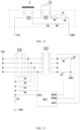
- the identification circuit on the circuit board 32 includes a controller MCU and a sampling resistor R5.
- the controller MCU is configured to obtain a first electrical parameter of the sampling resistor R5.
- the first electrical parameter may be a voltage at both ends of the sampling resistor R5 or a current flowing through the sampling resistor R5.
- the controller MCU obtains, based on the first electrical parameter of the sampling resistor R5, identity information of the identity circuit corresponding to the power supply module 321 against which the conductive member 1 is abutting. For example, an impedance of the identity circuit corresponding to the power supply module 321 against which the conductive member 1 is abutting is calculated based on the first electrical parameter of the sampling resistor R5.
- the identity circuit may be connected in series with the sampling resistor R5, so that the controller MCU may calculate the voltage on the identity circuit based on a partial voltage on the sampling resistor R5, and then calculate the impedance of the identity circuit.
- the plurality of identity circuits are connected in parallel with each other, so as not to interfere with each other. Only one identification circuit may be arranged on the circuit board 32, or only one sampling resistor R5 may be arranged thereon. Therefore, the plurality of identity circuits may be connected in series with the same sampling resistor R5. Alternatively, a plurality of sampling resistors R5 may be arranged on the circuit board 32, and the plurality of sampling resistors R5 are connected in series with the plurality of identity circuits in one-to-one correspondence.
- a line where the identity circuit is located is defined as a first line.
- the first electrode set 322 may be arranged on a second line connected in parallel with the first line.
- the heating element in the atomizer 21 is electrically connected between two electrodes in the first electrode set 322. Therefore, the heating element in the atomizer 21 is connected in parallel with the first line, and a resistance value of the second line includes a resistance value of the heating element in the atomizer 21.
- the resistance value on the first line may be made much greater than the resistance value on the second line.
- the resistance value on the first line may be made at least 800 times greater than the resistance value on the second line. In this way, the first line is almost short-circuited by the second line, or the first circuit is nearly open-circuited, thereby reducing power consumption of the first line.
- the resistance value of the heating element of the atomizer 21 is between 0.75 Q and 1.5 ⁇
- the resistance value on the second line is less than 3 ⁇
- the resistance value r5 of the sampling resistor R5 is about 300 K ⁇ .
- a voltage supplied by the power supply module 321 to the atomizer 21 is obtained based on the second electrical parameter of the detection resistor R6, and then the control circuit may determine whether the atomizer 21 is short-circuited or open-circuited based on the voltage supplied by the power supply module 321 to the atomizer 21.
- the control circuit may make a corresponding response when an abnormality (for example, a short circuit or an open circuit) occurs in the second line or the atomizer 21, for example, control the aerosol generation apparatus to send an alarm signal, or control to terminate electrical conduction between the power supply 31 and the power supply module 321, to protect the atomizer 21 and/or the power supply module 321 from the short circuit or the open circuit.
- a first switch Q1 may be controlled to turn on.
- the first switch Q1 and a second switch Q2 are arranged on the second line.
- the second switch Q2 is connected in series with the detection resistor R6, and the second switch Q2 and the detection resistor R6 connected in series with each other are connected in parallel with the first switch Q1 as a whole. Therefore, if one of the first switch Q1 and the second switch Q2 is turned on, the second line is closed, and the power supply 31 may supply power to the corresponding atomizer 21.
- the detection resistor R6 is short-circuited.
- the first switch Q1 may be turned off, and the second switch Q2 may be turned on.
- the second switch Q2 may be controlled to turn off, and the first switch Q1 may be controlled to turn on, to reduce energy consumption on the second line.
- the first switch Q1 and the second switch Q2 may be both connected to the controller MCU.
- the controller MCU may control the first switch Q1 to turn on or off, and the controller MCU may control the second switch Q2 to turn on and off.
- FIG. 14 to FIG. 16 An anode terminal VCC and a cathode terminal GND are arranged on the circuit board 32.
- the plurality of power supply modules 321 are connected in parallel between the anode terminal VCC and the cathode terminal GND, and the power supply 31 supplies power to the power supply module 321 through the anode terminal VCC and the cathode terminal GND.
- the controller MCU may be connected to an anode side of the detection resistor R6, and a cathode side of the detection resistor R6 is connected to the cathode terminal GND, so that the controller MCU may detect the voltage at both ends of the detection resistor R6.
- the plurality of atomizers 21 connected to the circuit board 32 may share a common cathode.
- An end of the plurality of identity circuits may be connected to a common anode, and an other end is connected to the cathode terminal GND through the sampling resistor R5.
- the controller MCU may be connected to an anode side of the sampling resistor R5, and a cathode side of the sampling resistor R5 is connected to the cathode terminal GND, so that the controller MCU may detect the voltage at both ends of the sampling resistor R5.
- the plurality of atomizers 21 are connected to the common cathode, or the atomizer 21 and the sampling resistor R5 are connected to the common cathode. Therefore, to prevent current backflow on the first line from causing inability to identify the identity circuit, the controller MCU may control the second switch Q2 to turn on and control the first switch Q1 to turn off when the identification circuit needs to identify the identity circuit. Upon completion of the identification of the identity circuit and confirmation of the identity of the corresponding power supply module 321 or the corresponding atomizer 21, the controller MCU may control the first switch Q1 to turn on, and may further control the second switch Q2 to turn off.
- the controller MCU may control a control circuit on the circuit board 32 to collect the usage parameters of the power supply module 321 or the atomizer 21.
- the usage parameters include a cumulative time used, a remaining time available, a quantity of cumulative puffs taken, a quantity of remaining puffs available, or the like.
- the usage parameters may be used to determine whether the liquid substrate in the corresponding atomizer 21 is exhausted, the remaining service life, or the like, or determine whether the power supply module 321 against which the conductive member 1 abuts needs to be switched.
- the control circuit may further be configured to stop the power supply assembly 3 from supplying power to the atomizer 21 or provide an indication when the usage parameter of the atomizer 21 is below a threshold or exceeds a preset threshold range.
- the smoking detector 7 may assist the control circuit in detecting whether the aerosol generation apparatus is smoked.
- the control circuit may accumulate the quantity of puffs based on the detection result of the smoking detector 7, to form the quantity of cumulative puffs taken.
- the control circuit may control a sensory prompter to make a response to prompt the user.
- the control circuit may control the power supply 31 to be electrically disconnected from the power supply module 321, so that the power supply 31 cannot output the power to the atomizer 21 through the power supply module 321.
- a storage unit corresponding to each power supply module 321 or each atomizer 21 is further arranged in the circuit board 32, and the storage unit stores a total quantity of puffs available of the atomizer 21.
- the quantity of remaining puffs available is a difference between the total quantity of puffs available and the quantity of cumulative puffs taken.
- the control circuit may control the sensory prompter to make a response to prompt the user.
- the control circuit may control the power supply 31 to be electrically disconnected from the power supply module, so that the power supply 31 cannot output the power to the atomizer 31 through the power supply module 321.
- the control circuit may obtain a cumulative duration of the power outputted from the corresponding first electrode set 322.
- the cumulative duration may be used as a basis for determining the cumulative time used.
- the control circuit may control the sensory prompter to make a response to prompt the user.
- the control circuit may control the power supply 31 to be electrically disconnected from the power supply module 321, so that the power supply 31 cannot output the power to the atomizer 21 through the power supply module 321.
- a storage unit corresponding to each power supply module 321 or each atomizer 21 is further arranged in the circuit board 32, and the storage unit stores a total time available of the atomizer 21.
- the remaining time available is a difference between the total time available and the cumulative time used.
- the control circuit may control the sensory prompter to make a response to prompt the user.
- the control circuit may control the power supply 31 to be electrically disconnected from the power supply module 321, so that the power supply 31 cannot output the power to the atomizer 21 through the power supply module 321.
- the usage parameter may further be another parameter that can indicate usage data or a degree of usage of the corresponding power supply module 321 or the corresponding atomizer 21.
- the usage parameter may be a parameter for indicating an amount of the liquid substrate in the storage cavity 211 or a remaining amount of the liquid substrate in the storage cavity 211.
- control circuit When the control circuit detects that the atomizer 21 corresponding to a piece of identity information reaches a condition of inability to continue to generate the aerosol or reaches a condition that the atomizer needs to be switched, the sensory prompter is controlled to make a response to prompt the user.
- control circuit may control the power supply 31 to be electrically disconnected from the power supply module 321, so that the power supply 31 cannot output the power to the atomizer 21 through the power supply module 321.
- the identity circuit may be arranged in the atomizer 21.
- the identity circuit may be connected in parallel with the heating element in the atomizer 21.
- the identification circuit may be arranged in the atomizer 21.
- the identity circuit and the identification circuit may be both arranged in the atomizer 21.
- a quantity of power supply modules 321 on the circuit board 32 is less than a quantity of atomizers 21.
- the identity circuit is arranged on the atomization assembly 2.
- the identification circuit may be arranged on the circuit board 32 or may be arranged on the atomization assembly 2.
- the control circuit may control the identification circuit to identify the identity information of the atomizer 21 to identify the usage parameter of the atomizer 21.
- the control circuit may control recording and storing the usage parameter of the atomizer 21.
- the control circuit may control the sensory prompter to make a response to prompt the user.
- the control circuit may control the power supply 31 to be electrically disconnected from the power supply module 321, so that the power supply 31 cannot output the power to the atomizer 21 through the power supply module 321.
Landscapes
- Disinfection, Sterilisation Or Deodorisation Of Air (AREA)
- Supply And Distribution Of Alternating Current (AREA)
- Electrostatic Spraying Apparatus (AREA)
Abstract
Description
- Embodiments of this application relate to the field of aerosol generation technologies, and in particular, to an aerosol generation apparatus.
- An aerosol generation apparatus is an apparatus that can atomize a liquid formulation to form an aerosol. However, in some exemplary prior art, the aerosol generation apparatus has a plurality of atomizers configured to store the liquid formulation. The plurality of atomizers may provide the aerosol to a user in turn. However, if the user does not switch the atomizer in time during use, dry heating may occur in the atomizer in an operating position due to excessively low content of a liquid substrate. If the atomizer is switched excessively early, the liquid substrate in the atomizer may be underutilized and wasted.
- Embodiments of this application provide an aerosol generation apparatus, so as to identify a usage parameter of an atomizer, so that a usage status of the atomizer may be identified.
- An embodiment of this application provides an aerosol generation apparatus, including:
- an atomization assembly, including a plurality of atomizers, where each of the atomizers is configured to operate independently when obtaining power;
- a power supply assembly, configured to selectively supply the power to at least one of the atomizers; and
- a control circuit, including a plurality of identity circuits associated with the plurality of atomizers in one-to-one correspondence, where each of the identity circuits has identity information for identifying a corresponding atomizer, and the control circuit further includes an identification circuit configured to identify the identity information; and
- the control circuit is configured to obtain an identification result of the identification circuit to determine the atomizer supplied with the power based on the identification result, and synchronously obtain a usage parameter of the determined atomizer.
- In an example, the control circuit is further configured to stop the power supply assembly from supplying the power to the atomizer or provide an indication when the usage parameter of the atomizer is below a threshold or exceeds a preset threshold range.
- In an example, the identity information includes an impedance of the identity circuit, and different identity circuits have different impedances.
- In an example, the aerosol generation apparatus further includes a sensory prompter, where the sensory prompter is configured to generate a sensory prompt signal when the usage parameter of the atomizer reaches a threshold.
- In an example, the usage parameter includes a cumulative time used or a remaining time available of the atomizer; or
the usage parameter includes a quantity of cumulative puffs taken or a quantity of remaining puffs available of the atomizer. - In an example, the identity circuit is arranged on the power supply assembly.
- In an example, the identity circuit is arranged on the atomization assembly.
- In an example, the power supply assembly includes a power supply and a circuit board, a power supply module is arranged on the circuit board, and the power supply assembly is configured to output the power to the atomizer through the power supply module.
- In an example, the identity circuit is arranged on the atomization assembly, a quantity of power supply modules is less than a quantity of atomizers, and the circuit board is configured to rotate relative to the atomization assembly.
- In an example, a plurality of power supply modules are arranged, and each of the atomizers is electrically connected to a different power supply module.
- The aerosol generation apparatus further includes a conductive member, and the conductive member is configured to be driven to change a position thereof relative to the circuit board and the atomization assembly at the same time, to selectively connect to one of the plurality of power supply modules.
- In an example, the conductive member is configured to establish a conductive path between the power supply module selectively connected to the conductive member and the corresponding atomizer, so that the atomizer is in a standby state or an operating state.
- In an example, the power supply module includes a first electrode set and a second electrode set associated with each other, the power supply module outputs the power through the first electrode set, and the conductive member is configured to abut against the power supply module having the second electrode set by abutting against the second electrode set.
- When the conductive member abuts against the power supply module, at least two electrodes in the second electrode set in the power supply module are connected to each other.
- In an example, the identification circuit and the identity circuit are both arranged on the circuit board.
- In an example, an anode terminal and a cathode terminal are arranged on the circuit board, a plurality of power supply modules are connected in parallel between the anode terminal and the cathode terminal, and the power supply is configured to supply the power to the circuit board through the anode terminal and the cathode terminal.
- In an example, the identification circuit includes a controller and a sampling resistor, each of the identity circuits is connected in series or in parallel with the sampling resistor, and the controller is configured to obtain a first electrical parameter of the sampling resistor and identify the identity information of the identity circuit based on the first electrical parameter.
- In an example, each power supply assembly further includes a first switch, a second switch, and a detection resistor connected in series with the second switch, and the second switch and the detection resistor connected in series are connected in parallel with the first switch as a whole.
- A line having the identity circuit is defined as a first line, the atomizer is arranged on a second line connected in parallel with the first line, and the atomizer, the detection resistor, and the second switch are connected in series on the second line.
- The controller is configured to obtain a second electrical parameter of the detection resistor, and determine whether an abnormality occurs in the second line based on the second electrical parameter.
- The controller is further configured to control at most one of the first switch and the second switch to turn on, and control the first switch to turn on when determining that the second line is normal.
- In an example, the plurality of atomizers are connected to a common cathode, and the controller is configured to control the second switch to turn on when identifying the identity information of the identity circuit, and control the first switch to turn on after identifying the identity information of the identity circuit.
- In the foregoing aerosol generation apparatus, the plurality of atomizers have identity circuits in one-to-one correspondence with the atomizers. Different identity circuits carry different identity information. The control circuit can identify different atomizers by identifying the identity information, and then can obtain the usage parameter of the corresponding atomizer, so that the usage status of the atomizer may be identified, thereby helping the user make a correct determination as to whether to switch the atomizer.
- One or more embodiments are exemplarily described with reference to pictures in accompanying drawings corresponding to the embodiments, and the exemplary descriptions do not constitute a limitation on the embodiments. Elements in the accompanying drawings that have same reference numerals are represented as similar elements, and unless otherwise particularly stated, the figures in the accompanying drawings are not drawn to scale.
-
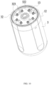
FIG. 1 is a schematic diagram of an aerosol generation apparatus according to an embodiment of this application. -
FIG. 2 is a cross-sectional view of an aerosol generation apparatus according to an embodiment of this application. -
FIG. 3 is another cross-sectional view of an aerosol generation apparatus according to an embodiment of this application. -
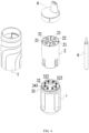
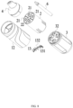
FIG. 4 is a schematic exploded view of an aerosol generation apparatus according to an embodiment of this application. -
FIG. 5 is a cross-sectional exploded view of an aerosol generation apparatus according to an embodiment of this application. -
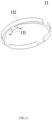
FIG. 6 is a schematic diagram of a conductive member according to an embodiment of this application. -
FIG. 7 is a cross-sectional exploded view of an aerosol generation apparatus according to another embodiment of this application. -
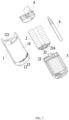
FIG. 8 is a schematic exploded view of an aerosol generation apparatus according to another embodiment of this application. -
FIG. 9 is a cross-sectional view of an aerosol generation apparatus according to another embodiment of this application. -
FIG. 10 is a schematic diagram showing that a conductive member abuts against a circuit board according to an embodiment of this application. -
FIG. 11 is a schematic diagram of connection between a conductive member and a power supply assembly according to an embodiment of this application. -
FIG. 12 is a schematic diagram showing that a conductive member does not abut against a power supply module according to an embodiment of this application. -
FIG. 13 is a schematic diagram showing that a conductive member abuts against a power supply module according to an embodiment of this application. -
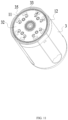
FIG. 14 is a schematic diagram of a power supply module having an identification circuit and an identity circuit according to an embodiment of this application. -
FIG. 15 is a schematic diagram of a layout of a circuit board having a plurality of power supply modules according to an embodiment of this application. -
FIG. 16 is a schematic diagram of a power supply module having an identification circuit and an atomizer having an identity circuit according to an embodiment of this application. - In the figures:
- 1. Conductive member; 11. First positioning mechanism; 12. Connector; 121. Separator; 13. Conductive piece; 131. Abutting pin; 132. Body; 14. First accommodation cavity; 15. Second accommodation cavity;
- 2. Atomization assembly;
- 21. Atomizer; 211. Storage cavity; 212. Atomization core; 213. Air supply channel; 214. First flexible member; 2141. First air channel; 215. Second flexible member; 2151. Second air channel; 216. Third electrode set; 22. First support;
- 3. Power supply assembly; 31. Power supply; 32. Circuit board; 321. Power supply module; 322. First electrode set; 323. Second electrode set; 33. Second support; 34. Anti-rotation member; 341. Third air channel; 35. Second positioning mechanism;
- 4. Suction nozzle assembly; 41. Air channel tube;
- 5. Threaded connector;
- 6. Rotating member; and
- 7. Smoking detector.
- Technical solutions in embodiments of this application are clearly and completely described below with reference to accompanying drawings in the embodiments of this application. Apparently, the described embodiments are merely some rather than all of the embodiments of this application. All other embodiments derived by a person of ordinary skill in the art based on the embodiments of this application without creative efforts shall fall within the protection scope of this application.
- Terms "first", "second", and "third" in this application are merely intended for a purpose of description, and shall not be understood as an indication or implication of relative importance or implicit indication of a quantity or an order of indicated technical features. All directional indications (for example, up, down, left, right, front, and back) in the embodiments of this application are only used for explaining relative position relationships, movement situations, or the like among the various components in a specific posture (as shown in the accompanying drawings). If the specific posture changes, the directional indication changes accordingly. In addition, terms "include", "have", and any variant thereof are intended to cover a non-exclusive inclusion. For example, a process, a method, a system, a product, or a device that includes a series of steps or units is not limited to the listed steps or units, and instead, further optionally includes a step or unit that is not listed, or further optionally includes another step or unit that is intrinsic to the process, the method, the product, or the device.
- Embodiments mentioned in the specification mean that particular features, structures, or characteristics described with reference to the embodiments may be included in at least one embodiment of this application. The phrase appearing at various locations in this specification does not necessarily indicate a same embodiment, and is not an independent or alternative embodiment exclusive to another embodiment. A person skilled in the art explicitly or implicitly understands that the embodiments described in this specification may be combined with other embodiments.
- It should be noted that when an element is considered to be "fixed" to another element, the element may be directly on the other element or an intermediate element may exist. When an element is considered to be "connected to" another element, the element may be directly connected to another element, or one or more intermediate elements may simultaneously exist between the element and another element. Terms "vertical", "horizontal", "left", "right", and similar expressions used in this specification are only for purpose of illustration, and do not represent a unique implementation.
- Referring to
FIG. 1 to FIG. 11 , an embodiment of this application provides an aerosol generation apparatus. The aerosol generation apparatus includes aconductive member 1, apower supply assembly 3, and anatomization assembly 2 having a plurality ofatomizers 21. Theconductive member 1 can be driven, so that theconductive member 1 can change a position. Therefore, theconductive member 1 can be configured to select theatomizer 21 electrically connected to thepower supply assembly 3, so that thepower supply assembly 3 can supply power to theatomizer 21 selected by theconductive member 1, and the selectedatomizer 21 can generate an aerosol. It should be noted that the "electrical connection" and the "electrical conduction" described in this application are two different concepts. The "electrical connection" means that a conductive line between two elements is connected, with a premise that a current flows from one element to the other element. The "electrical conduction" means that a current is flowing from one element to the other element. - The
atomization assembly 2 includes a plurality ofatomizers 21 independently of each other. Eachatomizer 21 is configured to operate independently when obtaining the power. Theatomizer 21 may be provided with astorage cavity 211 that can accommodate a liquid substrate. The liquid substrate stored in eachatomizer 21 may not exceed 5 ml, for example, may be approximately 2 ml. The liquid substrate may include a liquid containing a tobacco substance containing a volatile tobacco flavor ingredient, and may further be a liquid containing a non-tobacco substance. The liquid substrate may include water, a medicinal liquid, a solvent, ethanol, a plant extract, a perfume, a flavoring agent, or a vitamin mixture. The perfume may include a betel nut extracting solution, menthol, peppermint, spearmint oil, various fruity aroma ingredients, and the like, but is not limited thereto. The flavoring agent may include ingredients that may provide various aromas or flavors to a user. The vitamin mixture may be a mixture mixed with at least one of a vitamin A, a vitamin B, a vitamin C, and a vitamin E, but is not limited thereto. Based on different properties of the liquid substrate, the aerosol generation apparatus may be used in different fields, for example, medical treatment and electronic aerosol atomization. - The "plurality of" refers to two or more. In embodiments shown in
FIG. 4 andFIG. 8 , 4atomizers 21 are arranged, but is not limited thereto. At least twoatomizers 21 of the plurality ofatomizers 21 may be configured to accommodate different liquid substrates. Different liquid substrates include liquid substrates with different flavors or liquid substrates with different ingredients and proportions, so that different sensory experiences may be provided to the user by switching theatomizers 21. Certainly, in an embodiment, all of theatomizers 21 may contain the same liquid substrate. - Each
atomizer 21 may further have anatomization core 212. Theatomization core 212 is in fluid communication with thestorage cavity 211. Theatomization core 212 is configured to atomize the liquid substrate, so that the liquid substrate generates an aerosol. Theatomization core 212 may include a liquid absorbing element and a heating element. The liquid absorbing element may be a porous body or fiber, which can absorb the liquid substrate and guide the liquid substrate into an atomization range of the heating element. The heating element is configured to atomize at least part of the liquid substrate on the liquid absorbing element to form an aerosol. The heating element may be integrated on the liquid absorbing element, so that the heating element and the liquid absorbing element can form a whole. - Each
atomizer 21 may further have anair supply channel 213. Theair supply channel 213 provides at least part of an airflow channel in fluid communication with theatomization core 212 and asuction nozzle assembly 4. The aerosol generated through atomization of theatomization core 212 enters thesuction nozzle assembly 4 through the airflow channel. Thestorage cavity 211 may be arranged around theair supply channel 213, or theair supply channel 213 may be arranged on a side of thestorage cavity 211. At least part of thesuction nozzle assembly 4 may be held in a mouth of the user. The user inhales the aerosol through inhaling the suction nozzle assembly. - In an example, an atomization compartment in fluid communication with the
storage cavity 211 may be arranged in theatomizer 21. Theatomization core 212 is accommodated in the atomization compartment. Theair supply channel 213 is in fluid communication with the atomization compartment. Thestorage cavity 211 is located between thesuction nozzle assembly 4 and the atomization compartment. For example, thesuction nozzle assembly 4 is located above thestorage cavity 211, and the atomization compartment is located below thestorage cavity 211. - Alternatively, in another example, reference may be made to
FIG. 3 . At least part of theatomization core 212 is arranged in theair supply channel 213. A liquid guide hole is provided on theair supply channel 213. Theatomization core 212 is in fluid communication with thestorage cavity 211 through the liquid guide hole. The liquid substrate in thestorage cavity 211 may pass through the liquid guide hole to be absorbed by the liquid absorbing element and atomized by the heating element, or a part of the liquid absorbing element may pass through the liquid guide hole into thestorage cavity 211 to absorb and transfer the liquid substrate. - Referring to
FIG. 3 , eachatomizer 21 may further include a firstflexible member 214 having afirst air channel 2141. The firstflexible member 214 is arranged adjacent to thesuction nozzle assembly 4, and thefirst air channel 2141 is in fluid communication with theatomization core 212 in theatomizer 21. To be specific, thefirst air channel 2141 provides at least part of the airflow channel that communicates theatomization core 212 with thesuction nozzle assembly 4, and the firstflexible member 214 may seal an upper end of thecorresponding storage cavity 211. In an example, thefirst air channel 2141 is in fluid communication with theair supply channel 213, thefirst air channel 2141 is in fluid communication with theatomization core 212 through theair supply channel 213, and an upper end of theair supply channel 213 is fixed through the firstflexible member 214. For example, the upper end of theair supply channel 213 is in communication with thefirst air channel 2141 while being embedded in the firstflexible member 214 and fixed therein. - Referring to
FIG. 3 , eachatomizer 21 may further include a secondflexible member 215 having asecond air channel 2151. The secondflexible member 215 is arranged at an end opposite to the firstflexible member 214. The secondflexible member 215 may seal a lower end of thecorresponding storage cavity 211. Thestorage cavity 211 is located between the firstflexible member 214 and the secondflexible member 215. Thesecond air channel 2151 is in fluid communication with theatomization core 212 in theatomizer 21. Air outside theatomizer 21 may enter theair supply channel 213 through thesecond air channel 2151. Volatiles formed by atomizing the liquid substrate by theatomization core 212 are combined with the air entering from thesecond air channel 2151 to form an aerosol. - Reference may be made to
FIG. 2 . Thepower supply assembly 3 includes apower supply 31 and acircuit board 32. Thepower supply 31 may include any suitable battery. The battery may be a rechargeable battery, or the battery may be a disposable battery. In an embodiment, the battery is a lithium-ion battery. Alternatively, the battery may be a nickel metal hydride battery, a nickelcadmium battery, or a lithium-based battery, for example, a lithium cobalt battery, a lithium iron phosphate battery, a lithium titanate battery, or a lithium polymer battery. - One or more control circuits are arranged on the
circuit board 32. The control circuit may control power outputted by the battery. For example, the battery is enabled to output an alternating current, a direct current, or the like. Alternatively, for example, the battery is enabled to output a current or a voltage in the form of a pulse. - A plurality of
power supply modules 321 are arranged on thecircuit board 32, and thepower supply assembly 3 supplies power to a correspondingatomizer 21 through thepower supply modules 321. In an example, a quantity ofpower supply modules 321 is less than a quantity ofatomizers 21. Therefore, theatomizers 21 and thepower supply modules 321 may be moved or rotated relative to each other, to enable thepower supply modules 321 to switch theatomizers 21 electrically connected thereto. In an example, the quantity ofpower supply modules 321 may be greater than the quantity ofatomizers 21. In an example, a plurality ofpower supply modules 321 may be arranged, and a quantity ofpower supply modules 321 is equal to the quantity ofatomizers 21. Therefore, the plurality ofpower supply modules 321 and the plurality of atomizers may be electrically connected in a one-to-one manner or associated in a one-to-one manner. Eachatomizer 21 may be electrically connected to differentpower supply modules 321. - Based on a first aspect of this application, the plurality of
atomizers 21 are electrically connected to the plurality of power supply modules in one-to-one correspondence. After the aerosol generation apparatus is assembled, theatomizer 21 is configured to be non-switchable with thepower supply module 321 electrically connected thereto. The aerosol generation apparatus is configured such that all of theatomizers 21 cannot simultaneously operate to generate the aerosol, and only some of theatomizers 21 can obtain power from thepower supply modules 321 associated therewith and generate the aerosol at the same moment. - Based on this, in an embodiment, switching
elements 321 in one-to-one correspondence with the plurality of power supply modules are arranged. The user may control a selected switching element by inputting an instruction, so that thepower supply module 321 corresponding to the switching element can supply power to the correspondingatomizer 21, and the correspondingatomizer 21 can obtain the power to start the operation and enter a standby state or an operating state. - It should be noted that the "standby state" of the atomizer described in this application means that as long as the power supply supplies power to the power supply module, the power supply module may supply power to the corresponding atomizer. In other words, the atomizer in the standby state needs to wait for a further instruction. The further instruction is configured for allowing the power supply to supply power to the corresponding atomizer through the power supply module. After the further instruction is obtained, the atomizer may enter the operating state. The further instruction may be a smoking action of the user, or the like. For example, when the atomizer is in the standby state, the user may input a start instruction through an instruction input member (the instruction input member includes, but is not limited to, a smoking detector, a key switch, a sliding switch, a touch switch, an inductive switch, a remote switch, a touch screen, or the like). The power supply assembly electrically connects the power supply to the corresponding power supply module based on the start instruction, and therefore the power supply assembly can supply power to the corresponding atomizer through the power supply module, so that the atomizer is in the operating state and generates the aerosol.
- The "operating state" of the atomizer described in this application means that the power supply has already supplied power to the corresponding atomizer through the power supply module, and the atomizer is in a state of generating the aerosol by using the power.
- Alternatively, in another embodiment, each
power supply module 321 includes a first electrode set 322 and asecond electrode set 323. The plurality ofatomizers 21 are electrically connected to different first electrode sets 322. Thepower supply module 321 is configured to output power to theatomizer 21 associated therewith through the first electrode set 322 included therein. - The first electrode set 322 and the second electrode set 323 in the same
power supply module 321 are associated with each other. To be specific, an electrical connection between electrodes in the second electrode set 323, a magnitude of an impedance of a line between electrodes in the second electrode set 323, or the like determines whether a line between the first electrode set 322 associated therewith and thepower supply 31 is cut off, or determines whether thepower supply 31 can output the power through the first electrode set 322 associated with thesecond electrode set 323. For example, when the connection between two electrodes in the second electrode set 323 is cut off, the line between thepower supply 31 and the first electrode set 322 associated with the second electrode set 323 is therefore cut off. Accordingly, thepower supply 31 cannot supply power to the first electrode set 322, and cannot output power to thecorresponding atomization assembly 2 through thefirst electrode set 322. - In an example, the plurality of
atomizers 21 are electrically connected to a plurality of first electrode sets 322 in one-to-one correspondence. When thepower supply assembly 3 outputs the power through one of the first electrode sets 322, theatomizer 21 electrically connected to the first electrode set 322 may obtain power from the first electrode set 322, so that theatomizer 21 starts operating and enters the operating state. The heating element in theatomizer 21 can atomize the liquid substrate, and then theatomizer 21 may generate the aerosol. - Each
atomizer 21 may include athird electrode set 216. A quantity of electrodes in the third electrode set 216 may be equal to a quantity of electrodes in the first electrode set 322 electrically connected to theatomizer 21. In the embodiments shown inFIG. 12 to FIG. 14 , there are two electrodes in the third electrode set 316 and two electrodes in thefirst electrode set 322. In the embodiment shown inFIG. 16 , there are three electrodes in the third electrode set 216 and three electrodes in thefirst electrode set 322. The electrodes in the third electrode set 216 may be connected in one-to-one correspondence with the electrodes in the first electrode set 322 electrically connected to theatomizer 21. The connection may be a separable connection, for example, may be elastic abutment, or the connection may be an inseparable connection, for example, welding. - Alternatively, there is no third electrode set 216 in the
atomizer 21. Instead, eachatomizer 21 further includes a lead connected to the heating element. The lead extends out of theatomizer 21, and then is electrically connected to the first electrode set 322 corresponding to the atomizer. - Referring to
FIG. 3 , theatomization assembly 2 is connected to thecircuit board 32, so that theatomization assembly 2 and thecircuit board 32 cannot rotate relative to each other. - More specifically, the
atomization assembly 2 includes afirst support 22. The plurality ofatomizers 21 are fixed to thefirst support 22, so that the plurality ofatomizers 21 simultaneously remain stationary with respect to thefirst support 22. Thepower supply assembly 3 includes asecond support 33. Thecircuit board 32 may be integrated on thesecond support 33, so that thecircuit board 32 may remain stationary with respect to thesecond support 33. - In an example, an
anti-rotation member 34 extending to be inserted into theatomization assembly 2 is arranged on thesecond support 33, or an anti-rotation member extending to be inserted into thepower supply assembly 3 is arranged on thefirst support 22, or thefirst support 22 and thesecond support 33 are integrally formed. Therefore, thefirst support 22 and thesecond support 33 cannot rotate relative to each other, so that theatomizer 21 and thecircuit board 32 cannot rotate relative to each other. - As shown in
FIG. 3 , theanti-rotation member 34 may extend through thecircuit board 32. - In the embodiment shown in
FIG. 3 , theanti-rotation member 34 has athird air channel 341. Theanti-rotation member 34 extends from thesecond support 33, and an end thereof is inserted into the secondflexible member 215 of theatomizer 21 correspondingly arranged thereto. In addition, thethird air channel 341 in theanti-rotation member 34 is in fluid communication with thesecond air channel 2151 in the secondflexible member 215, and air enters thesecond air channel 2151 through thethird air channel 341, and then enters theair supply channel 213. A plurality ofanti-rotation members 34 having thethird air channel 341 may be arranged. At least twoanti-rotation members 34 are respectively inserted into twodifferent atomizers 21, so that thethird air channels 341 in the differentanti-rotation members 34 are respectively in fluid communication with differentair supply channels 213. - In an example, reference may be made to
FIG. 9 . The aerosol generation apparatus further includes a threaded connector. The threadedconnector 5 is connected to thefirst support 22 and thesecond support 33, so that thefirst support 22 and thesecond support 33 are fixed to each other and cannot rotate relative to each other. - The threaded
connector 5 may be threadably connected to both afirst connector 22 and asecond connector 33. The threadedconnector 5 may be connected to a center of thefirst support 22 and a center of thesecond support 33. Theanti-rotation member 34 shown in the foregoing embodiment may be arranged on thesecond support 33, and the threadedconnector 5 may extend through theanti-rotation member 34. The threadedconnector 5 may be spaced apart from theatomizer 21. - The
power supply 31 may be fixed to thesecond support 33. A part of thesecond support 33 may form a part of a shell of the aerosol generation apparatus, that is, the part of thesecond support 33 may be exposed and may be grasped or touched by the user. - Referring to
FIG. 5 to FIG. 8 , the aerosol generation apparatus further includes aconductive member 1. Theconductive member 1 is configured to simultaneously rotate relative to thecircuit board 32 and theatomization assembly 2, so that theconductive member 1 can be selectively connected to at least one of thepower supply modules 321. Alternatively, a position of theconductive member 1 may be changed by driving theconductive member 1 to enable theconductive member 1 to successively abut against the plurality ofpower supply modules 321. In addition, theconductive member 1 is rotated, so that theconductive member 1 can switch thepower supply module 321 abutting against the conductive member. When thepower supply module 321 abuts against the conductive member, theconductive member 1 can establish a conductive path between thepower supply module 321 selectively connected to the conductive member and the correspondingatomizer 21, so that theatomizer 21 associated with thepower supply module 321 is in a standby state or an operating state. Therefore, theconductive member 1 may be rotated to abut against differentpower supply modules 321 or successively abut against differentpower supply modules 321, so thatdifferent atomizers 21 may be in the standby state or in the operating state. In this way, the user may select theatomizer 21 in the standby state or the operating state to generate the aerosol after receiving the further instruction or directly generate the aerosol. - The
conductive member 1 may abut against thepower supply module 321 by abutting against the second electrode set 323 in thepower supply module 321. - In an example, reference may be made to
FIG. 13 . When theconductive member 1 abuts against the second electrode set 323, theconductive member 1 is connected in series between the first electrode set 322/atomizer 21 and thepower supply 31 that are associated. Therefore, when thepower supply 31 outputs power to theatomizer 21 through the first electrode set 322, an output current/voltage of thepower supply 31 needs to be transmitted to the corresponding first electrode set 322 through theconductive member 1. When theconductive member 1 is removed from the second electrode set 323, a line between thepower supply 31 and the first electrode set 322 associated with the second electrode set 323 is cut off. - There is only one
conductive member 1, or theconductive member 1 may abut against only one of the second electrode sets 323 at a same moment. Therefore, at the same moment, only oneatomizer 21 among the plurality ofatomizers 21 may be enabled to be in the standby state or in the operating state. - It should be noted that the only one
conductive member 1 is optional rather than mandatory. That theconductive member 1 abuts against only one of the second electrode sets 323 at the same moment is optional rather than mandatory. In another embodiment, a plurality ofconductive members 1 may be arranged. Alternatively, theconductive member 1 can simultaneously abut against a plurality of second electrode sets 323, so that thepower supply 31 can simultaneously supply power to the plurality ofpower supply modules 321. Therefore, the plurality ofatomizers 21 can simultaneously be in the standby state or in the operating state. - In an example, the
conductive member 1 may simultaneously rotate relative to thefirst support 22 and thesecond support 33. However, theconductive member 1 may be spaced apart from each of thefirst support 22 and thesecond support 33. - In an example, reference may be made to
FIG. 2 . Theconductive member 1 is rotatably connected to thefirst support 22 and/or thesecond support 33, so that theconductive member 1 may rotate simultaneously relative to thefirst support 22 and thesecond support 33. - Based on this, reference may be made to
FIG. 11 . Afirst positioning mechanism 11 may be arranged on theconductive member 1, and asecond positioning mechanism 35 may be arranged on thefirst support 22 or thesecond support 33. When theconductive member 1 abuts against at least one second electrode set 323, thefirst positioning mechanism 11 and thesecond positioning mechanism 35 are interlocked to prevent theconductive member 1 from continuing to rotate relative to thefirst support 22 and/or thesecond support 33, so as to ensure that theconductive member 1 maintains a stable electrical connection with the corresponding second electrode set 323, and ensure that thepower supply 31 can stably supply power to the first electrode set 322 associated with the second electrode set. - There are a plurality of manners of releasing the interlocking of the
first positioning mechanism 11 and thesecond positioning mechanism 35. One manner may be applying a greater force to drive theconductive member 1 to rotate relative to thefirst support 22 and/or thesecond support 33. - Alternatively, based on this, reference may be made to
FIG. 11 . Thefirst positioning mechanism 11 may be arranged on theconductive member 1, and asecond positioning mechanism 35 may be arranged on thefirst support 22 or thesecond support 33. Thefirst positioning mechanism 11 may be rotated to correspond to thesecond positioning mechanism 35. For example, thefirst positioning mechanism 11 may be rotated to engage with thesecond positioning mechanism 35. The aerosol generation apparatus is configured to generate a sensory prompt signal when thefirst positioning mechanism 11 is rotated to correspond to thesecond positioning mechanism 35, to prompt that theconductive member 1 abuts against the at least onesecond electrode set 323. - The sensory prompt signal may be one or more of sound, light, or vibration. The sensory prompt signal may be a vibration signal or a sound signal generated when the
first positioning mechanism 11 is rotated to engage with thesecond positioning mechanism 35. Alternatively, a signal collection circuit on thecircuit board 32 may generate an electrical parameter change when thefirst positioning mechanism 11 is rotated to correspond to thesecond positioning mechanism 35. Then the control circuit can control an LED light, a player, a motor, or the like to generate one or more signals including sound, light, and vibration based on the change in the electrical parameter. - In an example, reference may be made to
FIG. 2 . The aerosol generation apparatus further includes aconnector 12. Theconductive member 1 is held on theconnector 12, and theconductive member 1 can synchronously rotate with theconnector 12. Afirst accommodation cavity 14 is formed inside theconnector 12. At least part of theatomization assembly 2 is accommodated in thefirst accommodation cavity 14, and theatomization assembly 2 accommodated in thefirst accommodation cavity 14 cannot rotate relative to thecircuit board 32 in thefirst accommodation cavity 14. - Based on the second aspect of this application, the
suction nozzle assembly 4 is configured to rotate relative to theatomization assembly 2. When thesuction nozzle assembly 4 rotates relative to theatomization assembly 2, theatomizer 21 in fluid communication with thesuction nozzle assembly 4 can be switched. Therefore, theair supply channels 213 ofdifferent atomizers 21 may be in fluid communication with thesuction nozzle assembly 4 through rotation. - Based on this, in an example, reference may be made to
FIG. 3 . Thesuction nozzle assembly 4 includes anair channel tube 41. When the user holds at least part of thesuction nozzle assembly 4, a first end of theair channel tube 41 is in a mouth of the user, and a second end opposite to the first end is arranged in a direction of theatomization assembly 2. Aseparator 121 is arranged on the aerosol generation apparatus. Theseparator 121 extends along a radial direction of theatomization assembly 1, and theseparator 121 is located between theair channel tube 41 and theatomization assembly 2. A part of theseparator 121 is open, so that at least oneatomizer 21 of the plurality ofatomizers 21 can be in fluid communication with theair channel tube 41. Meanwhile, theseparator 121 can simultaneously block an airflow channel between one or more of the remainingatomizers 21 and theair channel tube 41. - More specifically, reference may be made to
FIG. 3 . Thefirst air channel 2141 on the firstflexible member 214 of one of theatomizers 21 is not blocked by theseparator 121. Therefore, theatomizer 21 is in fluid communication with thesuction nozzle assembly 4. The aerosol generated by theatomizer 21 can be transferred to theair channel tube 41 through the airflow channel, and then smoked into a mouth by the user. The firstflexible members 214 of the remainingatomizers 21 all elastically abut against theseparator 121, so that thefirst air channels 2141 of the firstflexible members 214 on theatomizers 21 are sealed or blocked by theseparator 121. Therefore, at the same time, only oneatomizer 21 of the plurality ofatomizers 21 may be enabled to be in fluid communication with thesuction nozzle assembly 4, and the remainingatomizers 21 are in an enclosed state. - In an example, reference may be made to
FIG. 3 . Thesuction nozzle assembly 4 is configured to be statically connected to theconnector 12, so that theconductive member 1 can rotate together with thesuction nozzle assembly 4 relative to thecircuit board 32 and theatomization assembly 2. Therefore, while rotating thesuction nozzle assembly 4 and enabling thesuction nozzle assembly 4 to select theatomizer 21 in fluid communication with the suction nozzle assembly, theconductive member 1 may be enabled to select the second electrode set 323 abutting against the conductive member, and vice versa. - Through arrangement, the
atomizer 21 corresponding to the second electrode set 323 abutting against theconductive member 1 and theatomizer 21 in fluid communication with thesuction nozzle assembly 4 are thesame atomizer 21. Therefore, a rotation operation may cause theatomizer 21 to be in the operating state when the first electrode set 322 associated with the second electrode set 323 supplies power to the correspondingatomizer 21. In addition, the aerosol generated by theatomizer 21 can be guided into thesuction nozzle assembly 4 through the airflow channel, and finally smoked into the mouth by the user. - When the
suction nozzle assembly 4 is statically connected to theconductive member 1, theconductive member 1 may be driven to rotate relative to theatomization assembly 2 and thecircuit board 32 by driving thesuction nozzle assembly 4 to rotate. Alternatively, thesuction nozzle assembly 4 may be driven to rotate relative to theatomization assembly 2 by driving theconductive member 1 to rotate. - More specifically, the
conductive member 1 may be made of a conductive material. Theconductive member 1 abuts against thesecond electrode set 323. Theconnector 12 is connected to theconductive member 1 and thesuction nozzle assembly 4. - At least part of the
connector 12 and theconductive member 1 may be made of a same material. At least part of theconnector 12 may be made of an insulating material. Theconnector 12 and theconductive member 1 may form an integrated structure by using an injection molding process. Theconnector 12 and theconductive member 1 may be integrally formed by stamping. Theconductive member 1 may be assembled with theconnector 12. For example, theconductive member 1 may be connected to theconnector 12 by a snap, or may be embedded in the connector. - In an example, reference is made to
FIG. 6 andFIG. 8 . Theconductive member 1 is made of metal, for example, copper. Theconductive member 1 has anabutting pin 131 and abody 132. Thebody 132 is configured to connect to theconnector 12. Theabutting pin 131 is configured to abut against the power supply module 3231, and theabutting pin 131 can synchronously rotate with theconnector 12 through thebody 132. Theabutting pin 131 and thebody 132 may be integrally formed. Referring toFIG. 6 , thebody 132 may be constructed as a ring. The ring is in a closed shape. Theabutting pin 131 extends toward an inner side of the ring. Alternatively, referring toFIG. 8 , thebody 132 may be constructed as an arc. The arc is in a curved but not closed shape. Theabutting pin 131 extends toward an inner side of the arc. It should be noted that thebody 132 may further be in another shape. - A quantity of abutting
pins 131 may be equal to a quantity of electrodes in thesecond electrode set 323. Each abuttingpin 131 may abut against each electrode in the second electrode set 323 in one-to-one correspondence. In an example shown inFIG. 6 , two abuttingpins 131 are arranged. Correspondingly, two electrodes are also arranged in thesecond electrode set 323. In an example shown inFIG. 8 , three abuttingpins 131 are arranged. Correspondingly, three electrodes are also arranged in thesecond electrode set 323. - The abutment between the
abutting pin 131 and thepower supply module 321 may be elastic abutment, to ensure that the electrical connection between theconductive member 1 and the correspondingpower supply module 321 is stable. Based on this, the electrodes in theabutting pin 131 and/or the second electrode set 323 are elastic. For example, the abuttingpin 131 may include an elastic piece and a contact arranged on the elastic piece for abutting against the power supply module. - An interior of the
connector 12 may be provided with thefirst accommodation cavity 14 for accommodating at least part of the atomization assembly. Thefirst accommodation cavity 14 may be arranged between thesuction nozzle assembly 4 and thecircuit board 32. - The interior of the
connector 12 may be provided with asecond accommodation cavity 15. At least part of thesuction nozzle assembly 4 may be accommodated in thesecond accommodation cavity 15, and thesuction nozzle assembly 4 is configured to be unable to rotate in thesecond accommodation cavity 15. In the embodiment shown inFIG. 5 , a part of theconnector 12 forms theseparator 121 described in any of the foregoing embodiments. Theseparator 121 defines at least part of a boundary of a bottom of thesecond accommodation cavity 15. - In an example, reference may be made to
FIG. 2 andFIG. 5 . The aerosol generation apparatus further includes a rotating member 16. At least part of the rotating member 16 may extend into an interior of theatomization assembly 2. The rotatingmember 6 is configured to rotate relative to theatomization assembly 2. Thesuction nozzle assembly 4 and theconductive member 1 are both statically connected to the rotatingmember 6, so that thesuction nozzle assembly 4 and theconductive member 1 also rotate relative to theatomization assembly 2 when the rotatingmember 6 rotates relative to theatomization assembly 2. - The rotating
member 6 may be driven to rotate by driving thesuction nozzle assembly 4 to rotate, and then theconductive member 1 is driven to rotate through the rotation of the rotatingmember 6. Alternatively, the rotatingmember 6 may be driven to rotate by driving theconductive member 1 to rotate, and then thesuction nozzle assembly 4 is driven to rotate through the rotation of the rotatingmember 6. Alternatively, theatomization assembly 2 is arranged around the rotatingmember 6. - In this way, the
conductive member 1 can rotate together with thesuction nozzle assembly 4 relative to thecircuit board 32 and theatomization assembly 2. Therefore, while rotating thesuction nozzle assembly 4 and enabling thesuction nozzle assembly 4 to select theatomizer 21 in fluid communication with the suction nozzle assembly, theconductive member 1 may be enabled to select the second electrode set 323 abutting against the conductive member, and vice versa. - In the embodiment shown in
FIG. 2 , an end of the rotatingmember 6 is statically connected to thesuction nozzle assembly 4, an other end of the rotatingmember 6 extends through theatomization assembly 2 and is rotatably connected to thepower supply assembly 3, and theconductive member 1 is arranged on a periphery of the rotatingmember 6. - It should be noted that the rotating
member 6 is optional rather than mandatory. In the embodiment shown inFIG. 9 , an inner side of theatomization assembly 2 is not provided with a rotating member that may rotate with thesuction nozzle assembly 4. - Based on a third aspect of this application, the
suction nozzle assembly 4 is configured to be simultaneously in fluid communication with the air supply channels of the plurality ofatomizers 21. - Based on the third aspect, in an example, the
suction nozzle assembly 4 is configured to be able to rotate relative to theatomization assembly 2. However, during the rotation of thesuction nozzle assembly 4 relative to theatomization assembly 2, the suction nozzle assembly being simultaneously in fluid communication with the air supply channels of the plurality ofatomizers 21 is not affected. Based on this, theconductive member 1 may be statically connected to thesuction nozzle assembly 4, so that theconductive member 1 can rotate together with thesuction nozzle assembly 4 relative to theatomization assembly 2. Alternatively, based on this, the rotation of theconductive member 1 relative to theatomization assembly 2 and the rotation of thesuction nozzle assembly 4 relative to theatomization assembly 2 are independent and unrelated. There may be no connection or transmission relationship between thesuction nozzle assembly 4 and theconductive member 1. - Based on the third aspect, in an example, the
suction nozzle assembly 4 is configured to be unable to rotate relative to theatomization assembly 2 and thecircuit board 32. - In a fourth aspect of this application, the aerosol generation apparatus further includes a
smoking detector 7 for detecting whether the aerosol generation apparatus is smoked. Thesmoking detector 7 is connected to acircuit board 32. Thecircuit board 32 is configured to control apower supply 31 to output power to a correspondingatomizer 21 through apower supply module 321 against which aconductive member 1 abuts when thesmoking detector 7 detects that the aerosol generation apparatus is smoked, so that the atomizer generates an aerosol. - Based on the fourth aspect, in an example, the aerosol generation apparatus has an air intake channel inside. The air intake channel is in fluid communication with air outside the aerosol generation apparatus and an air supply channel of the
atomizer 21. When the aerosol generation apparatus is smoked, the air outside the aerosol generation apparatus enters theair supply channel 213 through the air intake channel, and an air flow rate, an air flow direction, or an air pressure in the air intake channel changes. - The
smoking detector 7 is arranged at a position in fluid communication with the air intake channel, or thesmoking detector 7 is arranged in the air intake channel. Thesmoking detector 7 is configured to detect the air flow rate, the air flow direction, or detect the air pressure. Therefore, when the aerosol generation apparatus is smoked, thesmoking detector 7 can generate an electrical parameter change due to the change in the air flow rate, the air flow direction, or the air pressure at the position where the smoking detector is located, so as to determine whether the aerosol generation apparatus is smoked based on the electrical parameter change. - The
smoking detector 7 may form a start switch for thepower supply 31 to supply power to theatomization assembly 2. When theconductive member 1 abuts against at least onepower supply module 321, that is, theatomizer 21 has been in a standby state, thesmoking detector 7 can detect the smoking due to the electrical parameter change generated by the smoking if the user inhales the aerosol generation apparatus. Thecircuit board 32 controls thepower supply 31 to supply power to thepower supply module 321 based on a result that the smoking is detected. Thepower supply module 321 further supplies power to the corresponding atomizer through the first electrode set 322 therein, so that theatomizer 21 is in the operating state and generates the aerosol. After the smoking is stopped, based on the detection result of thesmoking detector 7, thecircuit board 32 controls to automatically interrupt power supply of thepower supply 31 to thepower supply module 321, so that the correspondingatomizer 21 stops continuously generating the aerosol. - The air intake channel may be simultaneously in fluid communication with the
air supply channels 213 of the plurality ofatomizers 21. In addition, when thesmoking detector 7 is configured as a start switch for thepower supply 31 to supply power to theatomization assembly 2, if thesmoking detector 7 is arranged at a position in fluid communication with the air intake channel, or thesmoking detector 7 is arranged in the air intake channel, only onesmoking detector 7 is required to enable thepower supply 31 to output power to the correspondingatomizer 21 through thepower supply module 321 against which theconductive member 1 abuts. - It should be noted that the
smoking detector 7 being configured as the start switch for thepower supply 31 to supply power to theatomization assembly 2 is optional rather than mandatory. The start instruction may further be inputted through another instruction input member (the instruction input member includes, but is not limited to, a key switch, a sliding switch, a touch switch, an inductive switch, a remote switch, a touch screen, or the like), to enable thepower supply 31 to output the power to the correspondingatomizer 21 through thepower supply module 321 against which theconductive member 1 abuts. - Based on a fifth aspect of this application, each
atomizer 21 or eachpower supply module 321 in the aerosol generation apparatus has unique identity information. A circuit on thecircuit board 32 can identify the identity information and distinguish betweendifferent atomizers 21 or differentpower supply modules 321 based on different identity information. Then the circuit on thecircuit board 32 may correspondingly record, store, and use usage parameters such as states, attributes, degrees of usage, or the remaining service life ofdifferent atomizers 21 or differentpower supply modules 321. - An identification circuit is arranged on the
circuit board 32. The identification circuit is configured to identify the identity information of thepower supply module 321 or theatomizer 21 when theconductive member 1 abuts against at least onepower supply module 321, and then identify thepower supply module 321 or theatomizer 21. The control circuit is configured to obtain an identification result of the identification circuit to determine thepower supply module 321 or theatomizer 21 supplied with power based on the identification result, and synchronously obtain the usage parameters of the determinedpower supply module 321 or thedetermined atomizer 21. - Based on this, the aerosol generation apparatus includes a plurality of identity circuits. The plurality of identity circuits are associated with the plurality of
power supply modules 321 or the plurality ofatomizers 21 in one-to-one correspondence. Different identity circuits carry different identity information. For example, each identity circuit has identity information for identifying the correspondingpower supply module 321 or the correspondingatomizer 21. Differentpower supply modules 321 oratomizers 21 may be identified through the identity circuit. Therefore, the identification circuit may identify thepower supply module 321 or theatomizer 21 corresponding to the identity information by identifying the identity information. In an example, the identity information includes an impedance of the identity circuit corresponding to the identity information. The impedance includes at least one of a reactance, a capacitive reactance, and an inductive reactance. Different identity circuits have different impedances. Therefore, the identification circuit may identify the identity circuit by identifying the impedance of different identity circuits, and identify thepower supply module 321 or theatomizer 21 associated with the identity circuit. - Reference may be made to
FIG. 14 andFIG. 16 . An identification resistor Rx is arranged on the identity circuit. For convenience of description, only 4 power supply modules are used for description. The 4power supply modules 321 are respectively defined as a first power supply module, a second power supply module, a third power supply module, and a fourth power supply module. Identity circuits in one-to-one correspondence with the 4 power supply modules are respectively a first identity circuit, a second identity circuit, a third identity circuit, and a fourth identity circuit. The identification resistors on the first identity circuit, the second identity circuit, the third identity circuit, and the fourth identity circuit are respectively a first identification resistor R1, a second identification resistor R2, a third identification resistor R3, and a fourth identification resistor R4. The impedances of the first identification resistor R1, the second identification resistor R2, the third identification resistor R3, and the fourth identification resistor R4 are different. - In an example, reference may be made to
FIG. 14 to FIG. 16 . The identity circuit is connected in parallel with at least part of thepower supply module 321 associated therewith, or with theatomizer 21 associated therewith, or with the heating element in theatomizer 21 associated therewith. Therefore, when the identity circuit operates, a voltage outputted by thepower supply module 321 to theatomizer 21 corresponding thereto is not affected, or a voltage obtained by theatomizer 21 from thepower supply module 321 corresponding thereto is not affected, or an operating voltage of the heating element in theatomizer 21 is not affected. It is intended not to affect an electric power of the heating element in theatomizer 21 for atomizing the liquid substrate. - More specifically, reference may be made to
FIG. 14 to FIG. 16 . The identity circuit may be connected in series with the second electrode set 323 in thepower supply module 321 associated therewith. Therefore, when theconductive member 1 abuts against the second electrode set 323, at least two electrodes in the second electrode set 323 are electrically connected. In this case, theconductive member 1 is connected in series with the identity circuit, theconductive member 1 is simultaneously connected in series with the first electrode set 322, and the identity circuit is connected in parallel with thefirst electrode set 322. Therefore, when theconductive member 1 is rotated to abut against at least one second electrode set 323, the identity circuit associated with the second electrode set 323 is therefore electrically connected to the identification circuit on thecircuit board 32, so that the identification circuit may enable identification of the identity circuit, and thecircuit board 32 starts recording and storing corresponding data of the associatedpower supply module 321 and/oratomizer 21. When theconductive member 1 is rotated to be disengaged from the second electrode set 323 in thepower supply module 321, a line between the identification circuit and the identity circuit associated with thepower supply module 321 is therefore cut off, and the identification circuit stops recording the usage parameters of thepower supply module 321 and/or theatomizer 21. In this example, the identity circuit is connected in parallel with the first electrode set 322 while being connected in series with the second electrode set 323, so that the operation of the identity circuit does not affect the power outputted by the first electrode set 322 to theatomizer 21, and does not affect the electric power of the heating element in theatomizer 21 for atomizing the liquid substrate. - It should be noted that other circuit connection manners may further be used to ensure that the operation of the identity circuit does not affect the electric power of the heating element in the
atomizer 21 for atomizing the liquid substrate, which are not illustrated herein one by one in this application. - In an example, the identity circuit is arranged on the
circuit board 32. Eachpower supply module 321 has an identity circuit uniquely connected thereto. The identification circuit on thecircuit board 32 includes a controller MCU and a sampling resistor R5. The controller MCU is configured to obtain a first electrical parameter of the sampling resistor R5. The first electrical parameter may be a voltage at both ends of the sampling resistor R5 or a current flowing through the sampling resistor R5. Then the controller MCU obtains, based on the first electrical parameter of the sampling resistor R5, identity information of the identity circuit corresponding to thepower supply module 321 against which theconductive member 1 is abutting. For example, an impedance of the identity circuit corresponding to thepower supply module 321 against which theconductive member 1 is abutting is calculated based on the first electrical parameter of the sampling resistor R5. - More specifically, reference may be made to
FIG. 15 . The identity circuit may be connected in series with the sampling resistor R5, so that the controller MCU may calculate the voltage on the identity circuit based on a partial voltage on the sampling resistor R5, and then calculate the impedance of the identity circuit. The calculation formula may be roughly
power supply module 321, and rx is an impedance of the identification resistor on each identity circuit. In other words, the impedance rx of the first identification resistor R1 on the first identity circuit is r1, the impedance rx of the second identification resistor R2 on the second identity circuit is r2, the impedance rx of the third identification resistor R3 on the third identity circuit is r3, and the impedance rx of the fourth identification resistor R4 on the fourth identity circuit is r4. - The plurality of identity circuits are connected in parallel with each other, so as not to interfere with each other. Only one identification circuit may be arranged on the
circuit board 32, or only one sampling resistor R5 may be arranged thereon. Therefore, the plurality of identity circuits may be connected in series with the same sampling resistor R5. Alternatively, a plurality of sampling resistors R5 may be arranged on thecircuit board 32, and the plurality of sampling resistors R5 are connected in series with the plurality of identity circuits in one-to-one correspondence. - A line where the identity circuit is located is defined as a first line. The first electrode set 322 may be arranged on a second line connected in parallel with the first line. The heating element in the
atomizer 21 is electrically connected between two electrodes in thefirst electrode set 322. Therefore, the heating element in theatomizer 21 is connected in parallel with the first line, and a resistance value of the second line includes a resistance value of the heating element in theatomizer 21. - Therefore, the resistance value on the first line may be made much greater than the resistance value on the second line. For example, the resistance value on the first line may be made at least 800 times greater than the resistance value on the second line. In this way, the first line is almost short-circuited by the second line, or the first circuit is nearly open-circuited, thereby reducing power consumption of the first line.
- In an example, the resistance value of the heating element of the
atomizer 21 is between 0.75 Q and 1.5 Ω, the resistance value on the second line is less than 3 Ω, and the resistance value r5 of the sampling resistor R5 is about 300 KΩ. - In an example, the resistance value of the heating element of the
atomizer 21 is between 0.75 Ω and 1.5 Ω, and the resistance value of the identification resistor Rx in the identity resistor is between 0.8 KS2 and 30 KS2. For example, the resistance value r1 of the first identification resistor R1 on the first identity circuit may be about 1 KS2, the resistance value r2 of the second identification resistor R2 on the second identity circuit may be about 1.5 KS2, the resistance value r3 of the third identification resistor R3 on the third identity circuit may be about 3 KS2, and the resistance value r4 of the fourth identification resistor R4 on the fourth identity circuit may be about 25.5 KΩ. - In an example, reference may be made to
FIG. 15 . A detection resistor R6 may further be arranged on the second line. The detection resistor R6 and the heating element of theatomizer 21 are connected in series with each other on the second line. Thecontroller 21 is configured to detect a second electrical parameter of the detection resistor R6. The second electrical parameter may be a voltage at both ends of the detection resistor R6, or may be a current flowing through the detection resistor R6. It is determined based on the second electrical parameter of the detection resistor R6 whether an abnormality occurs in the second line or theatomizer 21. For example, a voltage supplied by thepower supply module 321 to theatomizer 21 is obtained based on the second electrical parameter of the detection resistor R6, and then the control circuit may determine whether theatomizer 21 is short-circuited or open-circuited based on the voltage supplied by thepower supply module 321 to theatomizer 21. The control circuit may make a corresponding response when an abnormality (for example, a short circuit or an open circuit) occurs in the second line or theatomizer 21, for example, control the aerosol generation apparatus to send an alarm signal, or control to terminate electrical conduction between thepower supply 31 and thepower supply module 321, to protect theatomizer 21 and/or thepower supply module 321 from the short circuit or the open circuit. When the second electrical parameter of the detection resistor R6 is normal, a first switch Q1 may be controlled to turn on. - Based on this, reference may be made to
FIG. 15 . The first switch Q1 and a second switch Q2 are arranged on the second line. The second switch Q2 is connected in series with the detection resistor R6, and the second switch Q2 and the detection resistor R6 connected in series with each other are connected in parallel with the first switch Q1 as a whole. Therefore, if one of the first switch Q1 and the second switch Q2 is turned on, the second line is closed, and thepower supply 31 may supply power to the correspondingatomizer 21. In addition, when the first switch Q1 is turned on, the detection resistor R6 is short-circuited. - Therefore, when short-circuit or open-circuit detection needs to be performed on the
atomizer 21, the first switch Q1 may be turned off, and the second switch Q2 may be turned on. At other times, the second switch Q2 may be controlled to turn off, and the first switch Q1 may be controlled to turn on, to reduce energy consumption on the second line. - The first switch Q1 and the second switch Q2 may be both connected to the controller MCU. In addition, the controller MCU may control the first switch Q1 to turn on or off, and the controller MCU may control the second switch Q2 to turn on and off.
- In an example, reference may be made to
FIG. 14 to FIG. 16 . An anode terminal VCC and a cathode terminal GND are arranged on thecircuit board 32. The plurality ofpower supply modules 321 are connected in parallel between the anode terminal VCC and the cathode terminal GND, and thepower supply 31 supplies power to thepower supply module 321 through the anode terminal VCC and the cathode terminal GND. - In an example, as shown in
FIG. 15 , the controller MCU may be connected to an anode side of the detection resistor R6, and a cathode side of the detection resistor R6 is connected to the cathode terminal GND, so that the controller MCU may detect the voltage at both ends of the detection resistor R6. - In an example, as shown in
FIG. 15 , the plurality ofatomizers 21 connected to thecircuit board 32 may share a common cathode. An end of the plurality of identity circuits may be connected to a common anode, and an other end is connected to the cathode terminal GND through the sampling resistor R5. The controller MCU may be connected to an anode side of the sampling resistor R5, and a cathode side of the sampling resistor R5 is connected to the cathode terminal GND, so that the controller MCU may detect the voltage at both ends of the sampling resistor R5. - The plurality of
atomizers 21 are connected to the common cathode, or theatomizer 21 and the sampling resistor R5 are connected to the common cathode. Therefore, to prevent current backflow on the first line from causing inability to identify the identity circuit, the controller MCU may control the second switch Q2 to turn on and control the first switch Q1 to turn off when the identification circuit needs to identify the identity circuit. Upon completion of the identification of the identity circuit and confirmation of the identity of the correspondingpower supply module 321 or the correspondingatomizer 21, the controller MCU may control the first switch Q1 to turn on, and may further control the second switch Q2 to turn off. - After the controller MCU confirms the identity of the
power supply module 321 against which theconductive member 1 abuts, or after the controller MCU confirms the identity of theatomizer 21 associated with thepower supply module 321 against which theconductive member 1 abuts, the controller MCU may control a control circuit on thecircuit board 32 to collect the usage parameters of thepower supply module 321 or theatomizer 21. The usage parameters include a cumulative time used, a remaining time available, a quantity of cumulative puffs taken, a quantity of remaining puffs available, or the like. The usage parameters may be used to determine whether the liquid substrate in the correspondingatomizer 21 is exhausted, the remaining service life, or the like, or determine whether thepower supply module 321 against which theconductive member 1 abuts needs to be switched. - The control circuit may further be configured to stop the
power supply assembly 3 from supplying power to theatomizer 21 or provide an indication when the usage parameter of theatomizer 21 is below a threshold or exceeds a preset threshold range. - When the usage parameter includes the quantity of cumulative puffs taken, the
smoking detector 7 may assist the control circuit in detecting whether the aerosol generation apparatus is smoked. The control circuit may accumulate the quantity of puffs based on the detection result of thesmoking detector 7, to form the quantity of cumulative puffs taken. When the quantity of cumulative puffs taken reaches the threshold, the control circuit may control a sensory prompter to make a response to prompt the user. In addition, the control circuit may control thepower supply 31 to be electrically disconnected from thepower supply module 321, so that thepower supply 31 cannot output the power to theatomizer 21 through thepower supply module 321. - When the usage parameter includes the quantity of remaining puffs available, a storage unit corresponding to each
power supply module 321 or eachatomizer 21 is further arranged in thecircuit board 32, and the storage unit stores a total quantity of puffs available of theatomizer 21. The quantity of remaining puffs available is a difference between the total quantity of puffs available and the quantity of cumulative puffs taken. When the quantity of remaining puffs available decreases to the threshold, the control circuit may control the sensory prompter to make a response to prompt the user. In addition, the control circuit may control thepower supply 31 to be electrically disconnected from the power supply module, so that thepower supply 31 cannot output the power to theatomizer 31 through thepower supply module 321. - When the usage parameter includes the cumulative time used, the control circuit may obtain a cumulative duration of the power outputted from the corresponding
first electrode set 322. The cumulative duration may be used as a basis for determining the cumulative time used. When the cumulative time used reaches the threshold, the control circuit may control the sensory prompter to make a response to prompt the user. In addition, the control circuit may control thepower supply 31 to be electrically disconnected from thepower supply module 321, so that thepower supply 31 cannot output the power to theatomizer 21 through thepower supply module 321. - When the usage parameter includes the remaining time available, a storage unit corresponding to each
power supply module 321 or eachatomizer 21 is further arranged in thecircuit board 32, and the storage unit stores a total time available of theatomizer 21. The remaining time available is a difference between the total time available and the cumulative time used. When the remaining time available decreases to the threshold, the control circuit may control the sensory prompter to make a response to prompt the user. In addition, the control circuit may control thepower supply 31 to be electrically disconnected from thepower supply module 321, so that thepower supply 31 cannot output the power to theatomizer 21 through thepower supply module 321. - It should be noted that the usage parameter may further be another parameter that can indicate usage data or a degree of usage of the corresponding
power supply module 321 or the correspondingatomizer 21. Alternatively, the usage parameter may be a parameter for indicating an amount of the liquid substrate in thestorage cavity 211 or a remaining amount of the liquid substrate in thestorage cavity 211. - When the control circuit detects that the
atomizer 21 corresponding to a piece of identity information reaches a condition of inability to continue to generate the aerosol or reaches a condition that the atomizer needs to be switched, the sensory prompter is controlled to make a response to prompt the user. In addition, the control circuit may control thepower supply 31 to be electrically disconnected from thepower supply module 321, so that thepower supply 31 cannot output the power to theatomizer 21 through thepower supply module 321. - The
conductive member 1 is rotated relative to theatomization assembly 2 and thecircuit board 32. When theconductive member 1 is rotated to abut again against thepower supply module 321 against which the conductive member has abutted, the control circuit may immediately control the sensory prompter to make a response again to prompt the user after theatomizer 21 is identified by the identification circuit through the identity circuit associated with theatomizer 21 if theatomizer 21 associated with thepower supply module 321 has previously reached the condition of inability to continue to generate the aerosol or has reached the condition that the atomizer needs to be switched. In addition, the control circuit may control thepower supply 31 to be electrically disconnected from thepower supply module 321, so that thepower supply 31 cannot output the power to theatomizer 21 through thepower supply module 321. - It should be noted that in another embodiment, reference may be made to
FIG. 16 . The identity circuit may be arranged in theatomizer 21. The identity circuit may be connected in parallel with the heating element in theatomizer 21. Alternatively, in another embodiment, the identification circuit may be arranged in theatomizer 21. Alternatively, in another embodiment, the identity circuit and the identification circuit may be both arranged in theatomizer 21. - It should be noted that in another embodiment, a quantity of
power supply modules 321 on thecircuit board 32 is less than a quantity ofatomizers 21. For example, there are 4atomizers 21 and only onepower supply module 321. Therefore, only part of theatomizers 21 can be electrically connected to thepower supply module 321. Therefore, thepower supply module 321 may switch theatomizer 21 electrically connected thereto by causing theatomization assembly 2 and thecircuit board 32 to move relative to each other. In this embodiment, the identity circuit is arranged on theatomization assembly 2. The identification circuit may be arranged on thecircuit board 32 or may be arranged on theatomization assembly 2. When thepower supply module 321 is moved to be electrically connected to theatomizer 21 in theatomization assembly 2, the control circuit may control the identification circuit to identify the identity information of theatomizer 21 to identify the usage parameter of theatomizer 21. In addition, after the identification is completed, the control circuit may control recording and storing the usage parameter of theatomizer 21. When the usage parameter of theatomizer 21 reaches a preset value, the control circuit may control the sensory prompter to make a response to prompt the user. In addition, the control circuit may control thepower supply 31 to be electrically disconnected from thepower supply module 321, so that thepower supply 31 cannot output the power to theatomizer 21 through thepower supply module 321. - It should be noted that the preferred embodiments of this application are provided in the specification and the accompanying drawings of this application, but are not limited to the embodiments described in this specification. Further, a person of ordinary skill in the art may make improvements or modifications according to the foregoing descriptions, and all of the improvements and modifications shall fall within the protection scope of the appended claims of this application.
Claims (15)
- An aerosol generation apparatus, comprising:an atomization assembly (2), comprising a plurality of atomizers (21), wherein each of the atomizers (21) is configured to operate independently when supplied with power;a power supply assembly (3), configured to selectively supply the power to at least one of the atomizers (21); anda control circuit, comprising a plurality of identity circuits associated with the plurality of atomizers (21) in one-to-one correspondence, wherein:each of the identity circuits has identity information for identifying a corresponding atomizer (21), and the control circuit further comprises an identification circuit configured to identify the identity information; andthe control circuit is configured to obtain an identification result of the identification circuit to determine the atomizer (21) supplied with the power based on the identification result, and synchronously obtain a usage parameter of the determined atomizer (21).
- The aerosol generation apparatus according to claim 1, wherein the control circuit is further configured to stop the power supply assembly (3) from supplying the power to the atomizer (21) or provide an indication when the usage parameter of the atomizer (21) is below a threshold or exceeds a preset threshold range.
- The aerosol generation apparatus according to claim 1, wherein:the identity information comprises an impedance of the identity circuit; anddifferent identity circuits have different impedances.
- The aerosol generation apparatus according to claim 1, further comprising a sensory prompter, wherein the sensory prompter is configured to generate a sensory prompt signal when the usage parameter of the atomizer (21) reaches a threshold.
- The aerosol generation apparatus according to claim 1, wherein:the usage parameter comprises a cumulative time used or a remaining time available of the atomizer (21); orthe usage parameter comprises a quantity of cumulative puffs taken or a quantity of remaining puffs available of the atomizer (21).
- The aerosol generation apparatus according to claim 1, wherein:the identity circuit is arranged on the power supply assembly (3); orthe identity circuit is arranged on the atomization assembly (2).
- The aerosol generation apparatus according to claim 1, wherein:the power supply assembly (3) comprises a power supply (31) and a circuit board (32),a power supply module (321) is arranged on the circuit board (32); andthe power supply assembly (3) is configured to output the power to the atomizer (21) through the power supply module (321).
- The aerosol generation apparatus according to claim 7, wherein:the identity circuit is arranged on the atomization assembly (2);a quantity of power supply modules (321) is less than a quantity of atomizers (21); andthe circuit board (32) is configured to rotate relative to the atomization assembly (2).
- The aerosol generation apparatus according to claim 7, wherein:a plurality of power supply modules (321) are arranged;each of the atomizers (21) is electrically connected to a different power supply module (321);the aerosol generation apparatus further comprises a conductive member (1); andthe conductive member (1) is configured to be driven to change a position thereof relative to the circuit board (32) and the atomization assembly (2) at the same time, to selectively connect to one of the plurality of power supply modules (321).
- The aerosol generation apparatus according to claim 9, wherein the conductive member (1) is configured to establish a conductive path between the power supply module (321) selectively connected to the conductive member (1) and the corresponding atomizer (21), so that the atomizer (21) is in a standby state or an operating state.
- The aerosol generation apparatus according to claim 9, wherein:the power supply module (321) comprises a first electrode set (322) and a second electrode set (323) associated with each other;the power supply module (321) is configured to output the power through the first electrode set (322);the conductive member (1) is configured to abut against the power supply module (321) having the second electrode set (323) by abutting against the second electrode set (323); andwhen the conductive member (1) abuts against the power supply module (321), at least two electrodes in the second electrode set (323) in the power supply module (321) are connected to each other.
- The aerosol generation apparatus according to claim 7, wherein the identification circuit and the identity circuit are both arranged on the circuit board (32).
- The aerosol generation apparatus according to claim 12, wherein:an anode terminal and a cathode terminal are arranged on the circuit board (32);a plurality of power supply modules (321) are connected in parallel between the anode terminal and the cathode terminal; andthe power supply (31) is configured to supply the power to the circuit board (32) through the anode terminal and the cathode terminal.
- The aerosol generation apparatus according to claim 1, wherein:the identification circuit comprises a controller and a sampling resistor;each of the identity circuits is connected in series or in parallel with the sampling resistor; andthe controller is configured to obtain a first electrical parameter of the sampling resistor and identify the identity information of the identity circuit based on the first electrical parameter.
- The aerosol generation apparatus according to claim 14, wherein:each power supply assembly (3) further comprises a first switch (Q1), a second switch (Q2), and a detection resistor connected in series with the second switch (Q2), and the second switch (Q2) and the detection resistor connected in series are connected in parallel with the first switch (Q1) as a whole;a line having the identity circuit is defined as a first line, the atomizer (21) is arranged on a second line connected in parallel with the first line, and the atomizer (21), the detection resistor, and the second switch (Q2) are connected in series on the second line;the controller is configured to obtain a second electrical parameter of the detection resistor, and determine whether an abnormality occurs in the second line based on the second electrical parameter; andthe controller is further configured to control at most one of the first switch (Q1) and the second switch (Q2) to turn on, and control the first switch (Q1) to turn on when determining that the second line is normal, andwherein preferably:the plurality of atomizers (21) are connected to a common cathode; andthe controller is configured to control the second switch (Q2) to turn on when identifying the identity information of the identity circuit, and control the first switch (Q1) to turn on after identifying the identity information of the identity circuit.
Applications Claiming Priority (1)
| Application Number | Priority Date | Filing Date | Title |
|---|---|---|---|
| CN202311009040.8A CN119453565A (en) | 2023-08-09 | 2023-08-09 | Aerosol generating device |
Publications (2)
| Publication Number | Publication Date |
|---|---|
| EP4516142A2 true EP4516142A2 (en) | 2025-03-05 |
| EP4516142A3 EP4516142A3 (en) | 2025-05-21 |
Family
ID=92258874
Family Applications (1)
| Application Number | Title | Priority Date | Filing Date |
|---|---|---|---|
| EP24193177.3A Pending EP4516142A3 (en) | 2023-08-09 | 2024-08-06 | Aerosol generation apparatus |
Country Status (2)
| Country | Link |
|---|---|
| EP (1) | EP4516142A3 (en) |
| CN (1) | CN119453565A (en) |
Family Cites Families (4)
| Publication number | Priority date | Publication date | Assignee | Title |
|---|---|---|---|---|
| WO2014066730A1 (en) * | 2012-10-25 | 2014-05-01 | Lbs Imports, Llc. | Electronic cigarette |
| CA3013420C (en) * | 2016-02-16 | 2020-07-14 | Japan Tobacco Inc. | Flavor inhaler |
| EP4161304A4 (en) * | 2020-06-04 | 2024-07-24 | Blends Creative Inc. | PORTABLE VAPORIZER DEVICE WITH MULTIPLE CARTRIDGE CAPABILITY |
| US12102132B2 (en) * | 2020-07-15 | 2024-10-01 | Altria Client Services Llc | Nicotine electronic vaping devices having nicotine pre-vapor formulation level detection and auto shutdown |
-
2023
- 2023-08-09 CN CN202311009040.8A patent/CN119453565A/en active Pending
-
2024
- 2024-08-06 EP EP24193177.3A patent/EP4516142A3/en active Pending
Also Published As
| Publication number | Publication date |
|---|---|
| CN119453565A (en) | 2025-02-18 |
| EP4516142A3 (en) | 2025-05-21 |
Similar Documents
| Publication | Publication Date | Title |
|---|---|---|
| CN220712903U (en) | Aerosol generating device | |
| US12171271B2 (en) | Battery unit, flavor inhaler, method for controlling battery unit, and program | |
| KR102553781B1 (en) | Method for selecting electric resistance values of known resistances in the power supply unit of the suction component generating device and the power supply unit of the suction component generating device | |
| EP4640087A2 (en) | Aerosol generation device | |
| US20260013573A1 (en) | Aerosol generation system | |
| KR102329515B1 (en) | Power supply unit for aerosol generation device | |
| EP3855951A1 (en) | Dual battery electronic cigarette | |
| KR102511168B1 (en) | External unit for suction component generating device, suction component generating system, method for controlling external unit for suction component generating device, and program | |
| EP4527218A2 (en) | Aerosol generation device | |
| EP3698659B1 (en) | Battery unit, flavor inhaler, method for controlling battery unit, and program | |
| JP6856811B1 (en) | Power supply unit of aerosol generator | |
| CA2933861A1 (en) | Improved vaporization and dosage control for electronic vaporizing inhaler | |
| KR102631935B1 (en) | Aerosol generating device comprising a cartridge | |
| EP4505885A1 (en) | Aerosol generation apparatus | |
| KR102636655B1 (en) | Aerosol generating device comprising a cartridge | |
| CN221962871U (en) | Aerosol Generating Device | |
| EP4152984B1 (en) | Aerosol generating device comprising a cartridge | |
| CN114287674A (en) | Liquid storage assembly, atomizer, battery assembly, electronic atomization device and detection method | |
| CN119453566A (en) | Aerosol generating device | |
| CN119453565A (en) | Aerosol generating device | |
| EP4505886A1 (en) | Aerosol generation device | |
| US12622460B2 (en) | Aerosol generating device comprising cartridge | |
| CN215501369U (en) | An electronic atomization device | |
| KR102809086B1 (en) | Aerosol generating device with cartridge insertion recognition circuit that senses the cartridge, and user input process method | |
| KR20230024824A (en) | Cartridge for aerosol-generating device and aerosol-generating device comprising the same |
Legal Events
| Date | Code | Title | Description |
|---|---|---|---|
| PUAI | Public reference made under article 153(3) epc to a published international application that has entered the european phase |
Free format text: ORIGINAL CODE: 0009012 |
|
| STAA | Information on the status of an ep patent application or granted ep patent |
Free format text: STATUS: REQUEST FOR EXAMINATION WAS MADE |
|
| 17P | Request for examination filed |
Effective date: 20240806 |
|
| AK | Designated contracting states |
Kind code of ref document: A2 Designated state(s): AL AT BE BG CH CY CZ DE DK EE ES FI FR GB GR HR HU IE IS IT LI LT LU LV MC ME MK MT NL NO PL PT RO RS SE SI SK SM TR |
|
| PUAL | Search report despatched |
Free format text: ORIGINAL CODE: 0009013 |
|
| AK | Designated contracting states |
Kind code of ref document: A3 Designated state(s): AL AT BE BG CH CY CZ DE DK EE ES FI FR GB GR HR HU IE IS IT LI LT LU LV MC ME MK MT NL NO PL PT RO RS SE SI SK SM TR |
|
| RIC1 | Information provided on ipc code assigned before grant |
Ipc: A24F 40/53 20200101AFI20250411BHEP |