EP4516133A1 - Aerosol generation apparatus - Google Patents
Aerosol generation apparatus Download PDFInfo
- Publication number
- EP4516133A1 EP4516133A1 EP23865648.2A EP23865648A EP4516133A1 EP 4516133 A1 EP4516133 A1 EP 4516133A1 EP 23865648 A EP23865648 A EP 23865648A EP 4516133 A1 EP4516133 A1 EP 4516133A1
- Authority
- EP
- European Patent Office
- Prior art keywords
- aerosol
- generating device
- storage
- connector
- aerosol generating
- Prior art date
- Legal status (The legal status is an assumption and is not a legal conclusion. Google has not performed a legal analysis and makes no representation as to the accuracy of the status listed.)
- Pending
Links
Images




Classifications
-
- A—HUMAN NECESSITIES
- A24—TOBACCO; CIGARS; CIGARETTES; SIMULATED SMOKING DEVICES; SMOKERS' REQUISITES
- A24F—SMOKERS' REQUISITES; MATCH BOXES; SIMULATED SMOKING DEVICES
- A24F40/00—Electrically operated smoking devices; Component parts thereof; Manufacture thereof; Maintenance or testing thereof; Charging means specially adapted therefor
- A24F40/05—Devices without heating means
-
- A—HUMAN NECESSITIES
- A24—TOBACCO; CIGARS; CIGARETTES; SIMULATED SMOKING DEVICES; SMOKERS' REQUISITES
- A24C—MACHINES FOR MAKING CIGARS OR CIGARETTES
- A24C5/00—Making cigarettes; Making tipping materials for, or attaching filters or mouthpieces to, cigars or cigarettes
- A24C5/14—Machines of the continuous-rod type
- A24C5/18—Forming the rod
- A24C5/1885—Forming the rod for cigarettes with an axial air duct
-
- A—HUMAN NECESSITIES
- A24—TOBACCO; CIGARS; CIGARETTES; SIMULATED SMOKING DEVICES; SMOKERS' REQUISITES
- A24D—CIGARS; CIGARETTES; TOBACCO SMOKE FILTERS; MOUTHPIECES OF CIGARS OR CIGARETTES; MANUFACTURE OF TOBACCO SMOKE FILTERS OR MOUTHPIECES
- A24D3/00—Tobacco smoke filters, e.g. filter tips or filtering inserts; Filters specially adapted for simulated smoking devices; Mouthpieces of cigars or cigarettes
- A24D3/02—Manufacture of tobacco smoke filters
- A24D3/0275—Manufacture of tobacco smoke filters for filters with special features
- A24D3/0279—Manufacture of tobacco smoke filters for filters with special features with tubes
-
- A—HUMAN NECESSITIES
- A24—TOBACCO; CIGARS; CIGARETTES; SIMULATED SMOKING DEVICES; SMOKERS' REQUISITES
- A24F—SMOKERS' REQUISITES; MATCH BOXES; SIMULATED SMOKING DEVICES
- A24F40/00—Electrically operated smoking devices; Component parts thereof; Manufacture thereof; Maintenance or testing thereof; Charging means specially adapted therefor
- A24F40/40—Constructional details, e.g. connection of cartridges and battery parts
-
- A—HUMAN NECESSITIES
- A24—TOBACCO; CIGARS; CIGARETTES; SIMULATED SMOKING DEVICES; SMOKERS' REQUISITES
- A24F—SMOKERS' REQUISITES; MATCH BOXES; SIMULATED SMOKING DEVICES
- A24F40/00—Electrically operated smoking devices; Component parts thereof; Manufacture thereof; Maintenance or testing thereof; Charging means specially adapted therefor
- A24F40/40—Constructional details, e.g. connection of cartridges and battery parts
- A24F40/44—Wicks
-
- A—HUMAN NECESSITIES
- A24—TOBACCO; CIGARS; CIGARETTES; SIMULATED SMOKING DEVICES; SMOKERS' REQUISITES
- A24F—SMOKERS' REQUISITES; MATCH BOXES; SIMULATED SMOKING DEVICES
- A24F40/00—Electrically operated smoking devices; Component parts thereof; Manufacture thereof; Maintenance or testing thereof; Charging means specially adapted therefor
- A24F40/40—Constructional details, e.g. connection of cartridges and battery parts
- A24F40/48—Fluid transfer means, e.g. pumps
-
- A—HUMAN NECESSITIES
- A24—TOBACCO; CIGARS; CIGARETTES; SIMULATED SMOKING DEVICES; SMOKERS' REQUISITES
- A24F—SMOKERS' REQUISITES; MATCH BOXES; SIMULATED SMOKING DEVICES
- A24F40/00—Electrically operated smoking devices; Component parts thereof; Manufacture thereof; Maintenance or testing thereof; Charging means specially adapted therefor
- A24F40/50—Control or monitoring
-
- A—HUMAN NECESSITIES
- A24—TOBACCO; CIGARS; CIGARETTES; SIMULATED SMOKING DEVICES; SMOKERS' REQUISITES
- A24F—SMOKERS' REQUISITES; MATCH BOXES; SIMULATED SMOKING DEVICES
- A24F40/00—Electrically operated smoking devices; Component parts thereof; Manufacture thereof; Maintenance or testing thereof; Charging means specially adapted therefor
- A24F40/50—Control or monitoring
- A24F40/51—Arrangement of sensors
-
- A—HUMAN NECESSITIES
- A24—TOBACCO; CIGARS; CIGARETTES; SIMULATED SMOKING DEVICES; SMOKERS' REQUISITES
- A24F—SMOKERS' REQUISITES; MATCH BOXES; SIMULATED SMOKING DEVICES
- A24F40/00—Electrically operated smoking devices; Component parts thereof; Manufacture thereof; Maintenance or testing thereof; Charging means specially adapted therefor
- A24F40/10—Devices using liquid inhalable precursors
-
- A—HUMAN NECESSITIES
- A24—TOBACCO; CIGARS; CIGARETTES; SIMULATED SMOKING DEVICES; SMOKERS' REQUISITES
- A24F—SMOKERS' REQUISITES; MATCH BOXES; SIMULATED SMOKING DEVICES
- A24F40/00—Electrically operated smoking devices; Component parts thereof; Manufacture thereof; Maintenance or testing thereof; Charging means specially adapted therefor
- A24F40/20—Devices using solid inhalable precursors
Definitions
- the following description relates to an aerosol generating device.
- KR Patent Application Publication No. 2013-0003944 discloses an atomizer for an electronic cigarette.
- An aspect provides an aerosol generating device using a surface acoustic wave.
- Another aspect provides a stick configured to be mounted to or removed from an aerosol generating device using a surface acoustic wave.
- an aerosol generating device including an inhaler through which a user inhales an aerosol, a storage configured to store an aerosol forming substrate, an atomizer configured to atomize the aerosol forming substrate by using a surface acoustic wave, a connector configured to connect the storage to the atomizer and transmit the aerosol forming substrate from the storage to the atomizer, and a channel that crosses at least some of the inhaler, the storage, and the connector and through which the atomized aerosol forming substrate moves.
- the inhaler, the storage, the connector, and the channel may be formed integrally and may be separated from or combined with the aerosol generating device.
- the atomizer may include a surface acoustic wave generating element configured to generate a surface acoustic wave, a substrate element to which the generated surface acoustic wave is transmitted, and a chamber element configured to prevent the deviation of the atomized aerosol forming substrate.
- An end of the channel may communicate with the chamber element.
- the inhaler, the atomizer, and the connector may be formed integrally, and the storage may be separated from or combined with the aerosol generating device.
- the connector may transmit the aerosol forming substrate stored in the storage to the atomizer through a capillary phenomenon.
- An end of the connector may contact the substrate element, and the connector may include a passage element configured to move the aerosol forming substrate to the substrate element and a control element configured to control a rate of flow of the aerosol forming substrate that moves.
- the aerosol generating device may further include a power configured to supply power to the atomizer, the inhaler may include a respiratory sensor, and the atomizer may be connected to the respiratory sensor such that the generation of a surface acoustic wave is adjusted.
- a stick for an aerosol generating device including an inhaler through which a user inhales an aerosol, a storage configured to store an aerosol forming substrate, a connector configured to move the aerosol forming substrate stored in the storage, and a channel that crosses at least some of the inhaler, the storage, and the connector and through which an aerosol moves.
- the storage may be between the inhaler and the connector.
- the channel may be formed through a central portion of the inhaler, the storage, and the connector.
- the inhaler, the storage, and the connector may be formed as a cylinder.
- the channel may be formed to contact a side surface of the inhaler, the storage, and the connector.
- an aerosol generating device may use a surface acoustic wave.
- an aerosol generating device may provide a stick configured to be mounted to or removed from the aerosol generating device using a surface acoustic wave.
- FIGS. 1A and 1B are diagrams illustrating a stick for an aerosol generating device according to an embodiment.
- FIG. 1A illustrates the appearance of a stick 10 for an aerosol generating device according to an embodiment
- FIG. 1B illustrates the structure of the stick 10 for an aerosol generating device according to an embodiment.
- the stick 10 for an aerosol generating device may be mounted to or removed from the aerosol generating device.
- the stick 10 for an aerosol generating device may include an inhaler 100, a storage 200, and a connector 300.
- the inhaler 100 may be a portion for the inhalation of a user, and the user may apply inhale pressure to the inhaler 100 to inhale an aerosol.
- the inhaler 100 may be formed as a mouthpiece such that the user may inhale easily.
- the storage 200 may store an aerosol forming substrate.
- a storage may desirably store the aerosol forming substrate of 0.03 ml to 0.06 ml.
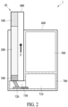
- FIG. 2 is a diagram illustrating an aerosol generating device according to an embodiment.
- the atomizer 700 may include a surface acoustic wave generating element 710 configured to generate a surface acoustic wave, a substrate element 720 to which the surface acoustic wave generated by the surface acoustic wave generating element 710 may be transmitted, and a chamber element 730 configured to prevent the deviation of an atomized aerosol.
- the surface acoustic wave generating element 710 may be designed to generate a surface acoustic wave only when the user inhales the aerosol generating device.
- the inhaler 100 may include a respiratory sensor (not shown). The respiratory sensor mounted to the inhaler 100 may sense that the user inhales the aerosol generating device and may generate an electrical control signal such that a surface acoustic wave generating element may operate only when the user inhales the aerosol generating device in the atomizer 700.
- the connector 300 of the stick 10 for an aerosol generating device may transmit the aerosol forming substrate stored in the storage 200 to the substrate element 720 of the atomizer 700.
- the aerosol forming substrate transmitted to the substrate element 720 may be atomized in an aerosol form after meeting a surface acoustic wave applied from the surface acoustic wave generating element 710.
- An aerosol generated by the aerosol forming substrate being atomized may be included by the chamber element 730.
- the control element may control, for example, a rate of flow of moving liquid by controlling the speed of the moving liquid.
- the control element (not shown) may be a micro pump.
- the control element (not shown) may supply the aerosol forming substrate to the substrate element 720 at a preset speed.
- a rate of flow of the liquid aerosol forming substrate supplied to the substrate unit 720 may be controlled to control an atomization amount of an aerosol generated in the atomizer 700.
- the channel 400 of the stick 10 for an aerosol generating device may communicate with the chamber element 730.
- an aerosol inside the chamber element 730 may be inhaled, in operation F, by the user along the channel 400.
- the user may inhale the aerosol generating device until all the aerosol forming substrate stored in the storage 200 is exhausted.
- the user may remove the stick 10 for an aerosol generating device from the aerosol generating device 1.
- the power 500 may supply power to another member of the aerosol generating device 1 or the atomizer 700 as needed.
- the stick 10 for an aerosol generating device may be mounted to or removed from the aerosol generating device.
- the stick 10 for an aerosol generating device may include the inhaler 100, the storage 200, and the connector 300.
- the stick 10 for an aerosol generating device may be formed to have an overall cylindrical appearance.
- Each of the inhaler 100, the storage 200, and the connector 300 included in the stick 10 for an aerosol generating device may be formed to have a cylinder appearance.
- the inhaler 100 may be a portion for the inhalation of a user, and the user may apply inhale pressure to the inhaler 100 to inhale an aerosol.
- the stick 10 for an aerosol generating device may include the inhaler 100, the storage 200, the connector 300, and the channel 400.
- the channel 400 may penetrate and cross the central portions of the inhaler 100, the storage 200, and the connector 300.
- the channel 400 may function as an airflow channel through which an aerosol that has atomized in the atomizer moves.
- the aerosol forming substrate may move from the storage 200 through the connector 300 to the atomizer and may be atomized in an aerosol form in the atomizer.
- the atomized aerosol may move, in operation F, through the channel 400 and may be inhaled by the user.
- the channel 400 may be formed as a cylinder corresponding to the shape of the stick 10 for an aerosol generating device, but the shape and structure of the channel 400 are not limited to the shape and structure illustrated in FIG. 3 .
- FIG. 4 is another diagram illustrating the aerosol generating device according to an embodiment.
- the aerosol generating device 1 may include the stick 10 for an aerosol generating device, the power 500, the housing 600, and the atomizer 700.
- the stick 10 for an aerosol generating device may be mounted to or removed from the aerosol generating device.
- the stick 10 for an aerosol generating device may include the inhaler 100, the storage 200, the connector 300, and the channel 400.
- the atomizer 700 may atomize an aerosol forming substrate by using a surface acoustic wave.
- the atomizer 700 may receive the aerosol forming substrate from the storage 200.
- the atomizer 700 may include a surface acoustic wave generating element 710 configured to generate a surface acoustic wave, a substrate element 720 to which the surface acoustic wave generated by the surface acoustic wave generating element 710 may be transmitted, and a chamber element 730 configured to prevent the deviation of an atomized aerosol.
- the surface acoustic wave generating element 710 may generate a surface acoustic wave configured to atomize a liquid.
- the surface acoustic wave generated by the surface acoustic wave generating element 710 may atomize a liquid aerosol forming substrate.
- the surface acoustic wave generated by the surface acoustic wave generating element 710 may be transmitted to the substrate element 720.
- the surface acoustic wave generating element 710 may be designed to generate a surface acoustic wave only when the user inhales the aerosol generating device.
- the inhaler 100 may include a respiratory sensor (not shown). The respiratory sensor mounted to the inhaler 100 may sense that the user inhales the aerosol generating device and may generate an electrical control signal such that the surface acoustic wave generating element may operate only when the user inhales the aerosol generating device in the atomizer 700.
- the connector 300 of the stick 10 for an aerosol generating device may transmit the aerosol forming substrate stored in the storage 200 to the substrate element 720 of the atomizer 700.
- the aerosol forming substrate transmitted to the substrate element 720 may be atomized in an aerosol form after meeting a surface acoustic wave applied from the surface acoustic wave generating element 710.
- An aerosol generated by the aerosol forming substrate being atomized may be included by the chamber element 730.
- the connector 300 may contact the substrate element 720.
- the shape of a portion where the substrate element 720 contacts the connector 300 may vary, corresponding to the shape of the connector 300 of which the central portion is penetrated by the channel 400.
- the connector 300 may include porous materials, such as a cotton wick, a porous ceramic, a paper filter, or the like.
- the connector 300 may move the aerosol forming substrate in the storage 200 to the atomizer through a capillary phenomenon.
- the connector may include a passage element (not shown) configured to move the aerosol forming substrate to the substrate element 720 and a control element (not shown) configured to control a rate of flow of the aerosol forming substrate that moves.
- the control element may control, for example, a rate of flow of moving liquid by controlling the speed of the moving liquid.
- the control element (not shown) may be a micro pump.
- the control element (not shown) may supply the aerosol forming substrate to the substrate element 720 at a preset speed.
- a control element (not shown) may control a rate of flow of the liquid aerosol forming substrate supplied to the substrate unit 720 to control an atomization amount of an aerosol generated in the atomizer 700.
- the channel 400 of the stick 10 for an aerosol generating device may communicate with the chamber element 730. As the user inhales the inhaler 100, an aerosol inside the chamber element 730 may be inhaled, in operation F, by the user along the channel 400.
- the power 500 may supply power to another member of the aerosol generating device 1 or the atomizer 700 as needed.
- the housing 600 may surround the atomizer 700, the power 500, and the stick 10 for an aerosol generating device to protect them against external shocks or other external disturbances and may form the appearance of the aerosol generating device 1.
- the housing 600 may include a mechanical structure for easily mounting or removing the stick 10 for an aerosol generating device.
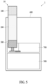
- FIG. 5 is yet another diagram illustrating the aerosol generating device according to an embodiment.
- the aerosol generating device, 1 may include the stick 10 for an aerosol generating device, the power 500, the housing 600, and the atomizer 700.
- the stick 10 for an aerosol generating device may include the inhaler 100, the storage 200, and the connector 300.
- the power 500 may be at a part inside the housing 600.
- the power 500 may be in a position opposite to the storage 200 with respect to the atomizer 700.
- FIG. 6 is still another diagram illustrating the aerosol generating device according to an embodiment.
- the aerosol generating device may include the inhaler 100, the storage 200, the connector 300, the power 500, the housing 600, and the atomizer 700.
- the atomizer 700 may include a surface acoustic wave generating element 710 configured to generate a surface acoustic wave, a substrate element 720 to which the surface acoustic wave generated by the surface acoustic wave generating element 710 may be transmitted, and a chamber element 730 configured to prevent the deviation of an atomized aerosol.
- the inhaler 100, the connector 300, the power 500, the housing 600, and the atomizer 700 may be formed integrally.
- the storage 200 may be mounted to or removed from the housing 500.
- the connector 300 may transmit the aerosol forming substrate stored in the storage 200 to the substrate element 720 of the atomizer 700.
- the storage 200 may desirably store the aerosol forming substrate of 0.5 ml to 1 ml.
- the user may inhale the aerosol generating device until all the aerosol forming substrate stored in the storage 200 is exhausted. When all the aerosol forming substrate stored in the storage 200 is exhausted, the user may remove the storage 200 from the aerosol generating device 1.
- FIG. 7 is a block diagram illustrating an aerosol generating device 900 according to another embodiment.
- the aerosol generating device 900 may include a controller 910, a sensing unit 920, an output unit 930, a battery 940, a heater 950, a user input unit 960, a memory 970, and a communication unit 980.
- the internal structure of the aerosol generating device 900 is not limited to the internal structure illustrated in FIG. 7 . It is to be understood by those having ordinary skill in the art to which the disclosure pertains that some of the components shown in FIG. 7 may be omitted or new components may be added according to the design of the aerosol generating device 900.
- the sensing unit 920 may sense a state of the aerosol generating device 900 or a state of an environment around the aerosol generating device 900 and may transmit sensing information obtained through the sensing to the controller 910. Based on the sensing information, the controller 910 may control the aerosol generating device 900 to control operations of the heater 950, may restrict smoking, may determine whether an aerosol generating article (e.g., a cigarette, a cartridge, etc.) is inserted, may display a notification, and may perform other functions.
- an aerosol generating article e.g., a cigarette, a cartridge, etc.
- the sensing unit 920 may include at least one of a temperature sensor 922, an insertion detection sensor 924, or a puff sensor 926. However, embodiments are not limited thereto.
- the temperature sensor 922 may sense a temperature at which the heater 950 (or an aerosol generating material) is heated.
- the aerosol generating device 900 may include a separate temperature sensor for sensing a temperature of the heater 950, or the heater 950 itself may perform a function as a temperature sensor.
- the temperature sensor 922 may be arranged around the battery 940 to monitor the temperature of the battery 940.
- the insertion detection sensor 924 may sense whether the aerosol generating article is inserted or removed.
- the insertion detection sensor 924 may include, for example, at least one of a film sensor, a pressure sensor, a light sensor, a resistive sensor, a capacitive sensor, an inductive sensor, or an infrared sensor, which may sense a signal change by the insertion or removal of the aerosol generating article.
- the puff sensor 926 may sense a puff from a user based on various physical changes in an airflow path or airflow channel. For example, the puff sensor 926 may sense the puff of the user based on any one of a temperature change, a flow change, a voltage change, and a pressure change.
- the sensing unit 9120 may further include at least one of a temperature/humidity sensor, an atmospheric pressure sensor, a magnetic sensor, an acceleration sensor, a gyroscope sensor, a position sensor (e.g., a global positioning system (GPS)), a proximity sensor, or a red, green, blue (RGB) sensor (e.g., an illuminance sensor), in addition to the sensors 922 through 926 described above.
- a function of each sensor may be intuitively inferable from its name by one of ordinary skill in the art, and thus, a detailed description thereof will be omitted herein.
- the output unit 930 may output information about the state of the aerosol generating device 900 and provide the information to the user.
- the output unit 930 may include at least one of a display 932, a haptic portion 934, or a sound outputter 936. However, embodiments are not limited thereto.
- the display 932 and a touchpad are provided in a layered structure to form a touchscreen, the display 932 may be used as an input device in addition to an output device.
- the display 932 may visually provide the information about the aerosol generating device 900 to the user.
- the information about the aerosol generating device 900 may include, for example, a charging/discharging state of the battery 940 of the aerosol generating device 900, a preheating state of the heater 950, an insertion/removal state of the aerosol generating article, a limited usage state (e.g., an abnormal article detected) of the aerosol generating device 900, or the like, and the display 931 may externally output the information.
- the display 932 may be, for example, a liquid-crystal display (LCD) panel, an organic light-emitting display (OLED) panel, or the like.
- the display 932 may also be in the form of a light-emitting diode (LED) device.
- LED light-emitting diode
- the haptic portion 934 may provide the information about the aerosol generating device 900 to the user in a haptic way by converting an electrical signal into a mechanical stimulus or an electrical stimulus.
- the haptic portion 934 may include, for example, a motor, a piezoelectric element, or an electrical stimulation device.
- the sound outputter 936 may provide the information about the aerosol generating device 900 to the user in an auditory way.
- the sound outputter 936 may convert an electric signal into a sound signal and externally output the sound signal.
- the battery 940 may supply power to be used to operate the aerosol generating device 900.
- the battery 940 may supply power to heat the heater 950.
- the battery 940 may supply power required for operations of the other components (e.g., the output unit 920, the output unit 930, the user input unit 960, the memory 970, and the communication unit 980) included in the aerosol generating device 900.
- the battery 940 may be a rechargeable battery or a disposable battery.
- the battery 940 may be, for example, a lithium polymer (LiPoly) battery, but examples are not limited thereto.
- the heater 950 may receive power from the battery 940 to heat the aerosol generating material.
- the aerosol generating device 900 may further include a power conversion circuit (e.g., a direct current (DC)-to-DC (DC/DC) converter) that converts power of the battery 940 and supplies the power to the heater 950.
- a power conversion circuit e.g., a direct current (DC)-to-DC (DC/DC) converter
- DC/AC DC-to-alternating current
- the controller 910, the sensing unit 920, the output unit 930, the user input unit 960, the memory 970, and the controller 910 may receive power from the battery 940 to perform functions.
- the aerosol generating device 900 may further include a power conversion circuit, for example, a low dropout (LDO) circuit or a voltage regulator circuit, which converts power of the battery 940 and supplies the power to respective components.
- LDO low dropout
- the heater 950 may be formed of a predetermined electrically resistive material that is suitable.
- the electrically resistive material may be a metal or a metal alloy including, for example, titanium, zirconium, tantalum, platinum, nickel, cobalt, chromium, hafnium, niobium, molybdenum, tungsten, tin, gallium, manganese, iron, copper, stainless steel, nichrome, or the like.
- the heater 130 may be implemented as a metal heating wire, a metal heating plate on which an electrically conductive track is arranged, a ceramic heating element, or the like.
- embodiments are not limited thereto.
- the heater 950 may be an induction heater.
- the heater 950 may include a susceptor that heats an aerosol generating material by generating heat through a magnetic field applied by a coil.
- the heater 950 may include a plurality of heaters.
- the heater 950 may include a first heater for heating a cigarette, and a second heater for heating a liquid.
- the user input unit 960 may receive information input from a user or may output information to the user.
- the user input unit 960 may include a keypad, a dome switch, a touchpad (e.g., a contact capacitive type, a pressure resistive film type, an infrared sensing type, a surface ultrasonic conduction type, an integral tension measurement type, a piezo effect method, etc.), a jog wheel, a jog switch, or the like, but examples are not limited thereto.
- the aerosol generating device 900 may further include a connection interface, such as a USB interface, and may be connected to another external device through the connection interface, such as a USB interface, to transmit and receive information or to charge the battery 940.
- the memory 970 which is hardware for storing various pieces of data processed in the aerosol generating device 900, may store data processed by the controller 910 and data to be processed thereby.
- the memory 970 may include at least one type of storage medium of a flash memory type memory, a hard disk type memory, a multimedia card micro type memory, a card type memory (e.g., an SD or XE memory), a random access memory (RAM), a static RAM (SRAM), a read-only memory (ROM), an electrically erasable programmable ROM (EEPROM), a programmable ROM (PROM), a magnetic memory, a magnetic disk, or an optical disk.
- the memory 970 may store an operating time of the aerosol generating device 900, a maximum number of puffs, a current number of puffs, at least one temperature profile, data associated with a smoking pattern of the user, or the like.
- the communication unit 980 may include at least one component to communicate with another electronic device.
- the communication unit 980 may include a short-range wireless communication unit 982 and a wireless communication unit 984.
- the short-range wireless communication unit 982 may include a Bluetooth communication unit, a Bluetooth low energy (BLE) communication unit, a near field communication unit, a WLAN (Wi-Fi) communication unit, a ZigBee communication unit, an infrared data association (IrDA) communication unit, a Wi-Fi direct (WFD) communication unit, an ultra-wideband (UWB) communication unit, and an Ant+ communication unit.
- BLE Bluetooth low energy
- Wi-Fi Wireless Fidelity
- ZigBee ZigBee communication unit
- IrDA infrared data association
- WFD Wi-Fi direct
- UWB ultra-wideband
- the wireless communication unit 984 may include, for example, a cellular network communicator, an Internet communicator, a computer network (e.g., a local area network (LAN) or a wide-area network (WAN)) communicator, or the like. However, embodiments are not limited thereto.
- the wireless communication unit 984 may use subscriber information (e.g., international mobile subscriber identity (IMSI)) to identify and authenticate the aerosol generating device 900 in a communication network.
- IMSI international mobile subscriber identity
- the controller 910 may control the overall operation of the aerosol generating device 900.
- the controller 910 may include at least one processor.
- the processor may be implemented as an array of a plurality of logic gates or may be implemented as a combination of a general-purpose microprocessor and a memory in which a program executable by the microprocessor is stored.
- a program executable by the microprocessor is stored.
- it is to be understood by one of ordinary skill in the art to which the present disclosure pertains that it may be implemented in other types of hardware.
- the controller 910 may control the output unit 930 based on the sensing result obtained by the sensing unit 920. For example, when a number of puffs counted through the puff sensor 926 reaches a preset number, the controller 910 may inform the user that the aerosol generating device 900 is to be ended soon, through at least one of the display 932, the haptic portion 934, or the sound outputter 936.
Landscapes
- Catching Or Destruction (AREA)
- Containers And Packaging Bodies Having A Special Means To Remove Contents (AREA)
- Special Spraying Apparatus (AREA)
Abstract
Description
- The following description relates to an aerosol generating device.
- Recently, demands for alternatives to overcome the disadvantages of general cigarettes have increased. For example,
KR Patent Application Publication No. 2013-0003944 - The above description is information the inventor(s) acquired during the course of conceiving the present disclosure, or already possessed at the time, and was not necessarily publicly known before the present application was filed.
- An aspect provides an aerosol generating device using a surface acoustic wave.
- Another aspect provides a stick configured to be mounted to or removed from an aerosol generating device using a surface acoustic wave.
- According to an aspect, there is provided an aerosol generating device including an inhaler through which a user inhales an aerosol, a storage configured to store an aerosol forming substrate, an atomizer configured to atomize the aerosol forming substrate by using a surface acoustic wave, a connector configured to connect the storage to the atomizer and transmit the aerosol forming substrate from the storage to the atomizer, and a channel that crosses at least some of the inhaler, the storage, and the connector and through which the atomized aerosol forming substrate moves.
- The inhaler, the storage, the connector, and the channel may be formed integrally and may be separated from or combined with the aerosol generating device.
- The atomizer may include a surface acoustic wave generating element configured to generate a surface acoustic wave, a substrate element to which the generated surface acoustic wave is transmitted, and a chamber element configured to prevent the deviation of the atomized aerosol forming substrate.
- An end of the channel may communicate with the chamber element.
- The inhaler, the atomizer, and the connector may be formed integrally, and the storage may be separated from or combined with the aerosol generating device.
- The connector may transmit the aerosol forming substrate stored in the storage to the atomizer through a capillary phenomenon.
- An end of the connector may contact the substrate element, and the connector may include a passage element configured to move the aerosol forming substrate to the substrate element and a control element configured to control a rate of flow of the aerosol forming substrate that moves.
- The aerosol generating device may further include a power configured to supply power to the atomizer, the inhaler may include a respiratory sensor, and the atomizer may be connected to the respiratory sensor such that the generation of a surface acoustic wave is adjusted.
- According to another aspect, there is provided a stick for an aerosol generating device including an inhaler through which a user inhales an aerosol, a storage configured to store an aerosol forming substrate, a connector configured to move the aerosol forming substrate stored in the storage, and a channel that crosses at least some of the inhaler, the storage, and the connector and through which an aerosol moves.
- The storage may be between the inhaler and the connector.
- The channel may be formed through a central portion of the inhaler, the storage, and the connector.
- The inhaler, the storage, and the connector may be formed as a cylinder.
- The channel may be formed to contact a side surface of the inhaler, the storage, and the connector.
- According to an aspect, an aerosol generating device may use a surface acoustic wave.
- According to another aspect, an aerosol generating device may provide a stick configured to be mounted to or removed from the aerosol generating device using a surface acoustic wave.
-
-
FIGS. 1A, 1B are diagrams illustrating a stick for an aerosol generating device of an embodiment. -
FIG. 2 is a diagram illustrating an aerosol generating device according to an embodiment. -
FIGS. 3A and 3B are other diagrams illustrating the stick for an aerosol generating device according to an embodiment. -
FIG. 4 is another diagram illustrating the aerosol generating device according to an embodiment. -
FIG. 5 is yet another diagram illustrating the aerosol generating device of an embodiment. -
FIG. 6 is still another diagram illustrating the aerosol generating device of an embodiment. -
FIG. 7 is a block diagram illustrating an aerosol generating device of another embodiment. - Hereinafter, embodiments are described in detail with reference to the accompanying drawings. The following description is one of several aspects of embodiments and the following description forms part of the detailed description of the embodiments. In describing an embodiment, a detailed description of a well-known function or configuration is omitted to clarify the present invention.
- However, various alterations and modifications may be made to the embodiments. Here, the embodiments are not construed as limited to the disclosure. The embodiments should be understood to include all changes, equivalents, and replacements within the idea and the technical scope of the disclosure.
- In addition, terms or words used in the present specification and claims should not be construed in general meanings or dictionary definitions, and based on a principle that the inventor may properly define the concept of terms to best describe their invention, the terms or words should be construed as meanings and concepts consistent with the technical idea of the invention according to an embodiment.
- The singular forms "a", "an", and "the" are intended to include the plural forms as well, unless the context clearly indicates otherwise. It will be further understood that the terms "comprises/comprising" and/or "includes/including" when used herein, specify the presence of stated features, integers, steps, operations, elements, and/or components, but do not preclude the presence or addition of one or more other features, integers, steps, operations, elements, components and/or groups thereof.
- Unless otherwise defined, all terms including technical and scientific terms used herein have the same meaning as commonly understood by one of ordinary skill in the art to which embodiments belong. It will be further understood that terms, such as those defined in commonly used dictionaries, should be interpreted as having a meaning that is consistent with their meaning in the context of the relevant art and will not be interpreted in an idealized or overly formal sense unless expressly so defined herein.
- When describing the embodiments with reference to the accompanying drawings, like reference numerals refer to like constituent elements and a repeated description related thereto will be omitted. In the description of embodiments, detailed description of well-known related structures or functions will be omitted when it is deemed that such description will cause ambiguous interpretation of the present disclosure.
- Also, in the description of the components, terms such as first, second, A, B, (a), (b) or the like may be used herein when describing components of the present disclosure. These terms are used only for the purpose of discriminating one constituent element from another constituent element, and the nature, the sequences, or the orders of the constituent elements are not limited by the terms. When one constituent element is described as being "connected", "coupled", or "attached" to another constituent element, it should be understood that one constituent element can be connected or attached directly to another constituent element, and an intervening constituent element can also be "connected", "coupled", or "attached" to the constituent elements.
- The same name may be used to describe an element included in the embodiments described above and an element having a common function. Unless otherwise mentioned, the descriptions of the example embodiments may be applicable to the following example embodiments, and thus duplicated descriptions will be omitted for conciseness.
-
FIGS. 1A and 1B are diagrams illustrating a stick for an aerosol generating device according to an embodiment. - More specifically,
FIG. 1A illustrates the appearance of astick 10 for an aerosol generating device according to an embodiment, andFIG. 1B illustrates the structure of thestick 10 for an aerosol generating device according to an embodiment. - The
stick 10 for an aerosol generating device according to an embodiment may be mounted to or removed from the aerosol generating device. Referring toFIG. 1A , thestick 10 for an aerosol generating device according to an embodiment may include aninhaler 100, astorage 200, and aconnector 300. Theinhaler 100 may be a portion for the inhalation of a user, and the user may apply inhale pressure to theinhaler 100 to inhale an aerosol. Theinhaler 100 may be formed as a mouthpiece such that the user may inhale easily. Thestorage 200 may store an aerosol forming substrate. A storage may desirably store the aerosol forming substrate of 0.03 ml to 0.06 ml. An end of thestorage 200 may face and be connected to an end of theinhaler 100. Theconnector 300 may connect thestorage 200 to an atomizer in the aerosol generating device as described below. Theconnector 300 may move the aerosol forming substrate stored in thestorage 200 to the atomizer. Theconnector 300 may include porous materials, such as a cotton wick, a porous ceramic, a paper filter, or the like. Theconnector 300 may move the aerosol forming substrate in thestorage 200 to the atomizer through a capillary phenomenon. Thestorage 200 may be between theinhaler 100 and theconnector 300. - Referring to
FIG. 1B , thestick 10 for an aerosol generating device according to an embodiment may include theinhaler 100, thestorage 200, theconnector 300, and achannel 400. Thechannel 400 may cross theinhaler 100, thestorage 200, and theconnector 300. Thechannel 400 may face all theinhaler 100, thestorage 200, and theconnector 300. Thechannel 400 may function as an airflow channel through which an aerosol that has atomized in the atomizer moves. The aerosol forming substrate may move through theconnector 300 to the atomizer and may be atomized in an aerosol form in the atomizer. As the user inhales theinhaler 100, the atomized aerosol may move, in operation F, through thechannel 400 and may be inhaled by the user. Thechannel 400 may face the side surfaces of theinhaler 100, thestorage 200, and theconnector 300. The shape and structure of thechannel 400 are not limited to the shape and structure illustrated inFIG. 1 . -
FIG. 2 is a diagram illustrating an aerosol generating device according to an embodiment. - Referring to
FIG. 2 , anaerosol generating device 1, according to an embodiment, may include thestick 10 for an aerosol generating device, apower 500, ahousing 600, and anatomizer 700. Thestick 10 for an aerosol generating device may be mounted to or removed from the aerosol generating device. Thestick 10 for an aerosol generating device may include theinhaler 100, thestorage 200, theconnector 300, and thechannel 400. Theatomizer 700 may atomize an aerosol forming substrate by using a surface acoustic wave. Theatomizer 700 may receive the aerosol forming substrate from thestorage 200. - The
atomizer 700 may include a surface acousticwave generating element 710 configured to generate a surface acoustic wave, asubstrate element 720 to which the surface acoustic wave generated by the surface acousticwave generating element 710 may be transmitted, and achamber element 730 configured to prevent the deviation of an atomized aerosol. - The surface acoustic
wave generating element 710 may generate a surface acoustic wave configured to atomize a liquid. The surface acoustic wave may be an acoustic wave transmitted along the surface of an elastic body substrate and may be generated from an electrical signal as a result of a piezoelectric effect. The surface acoustic wave generated by the surface acousticwave generating element 710 may atomize a liquid aerosol forming substrate. The surface acoustic wave generated by the surface acousticwave generating element 710 may be transmitted to thesubstrate element 720. - The surface acoustic
wave generating element 710 may be designed to generate a surface acoustic wave only when the user inhales the aerosol generating device. For example, theinhaler 100 may include a respiratory sensor (not shown). The respiratory sensor mounted to theinhaler 100 may sense that the user inhales the aerosol generating device and may generate an electrical control signal such that a surface acoustic wave generating element may operate only when the user inhales the aerosol generating device in theatomizer 700. - The
connector 300 of thestick 10 for an aerosol generating device may transmit the aerosol forming substrate stored in thestorage 200 to thesubstrate element 720 of theatomizer 700. The aerosol forming substrate transmitted to thesubstrate element 720 may be atomized in an aerosol form after meeting a surface acoustic wave applied from the surface acousticwave generating element 710. An aerosol generated by the aerosol forming substrate being atomized may be included by thechamber element 730. - An end of the
connector 300 may contact thesubstrate element 720. For example, theconnector 300 may include porous materials, such as a cotton wick, a porous ceramic, a paper filter, or the like. Theconnector 300 may move the aerosol forming substrate in thestorage 200 to the atomizer through a capillary phenomenon. Alternatively, the connector may include a passage element (not shown) configured to move the aerosol forming substrate to thesubstrate element 720 and a control element (not shown) configured to control a rate of flow of the aerosol forming substrate that moves. - The control element (not shown) may control, for example, a rate of flow of moving liquid by controlling the speed of the moving liquid. The control element (not shown) may be a micro pump. The control element (not shown) may supply the aerosol forming substrate to the
substrate element 720 at a preset speed. A rate of flow of the liquid aerosol forming substrate supplied to thesubstrate unit 720 may be controlled to control an atomization amount of an aerosol generated in theatomizer 700. - The
channel 400 of thestick 10 for an aerosol generating device may communicate with thechamber element 730. As the user inhales theinhaler 100, an aerosol inside thechamber element 730 may be inhaled, in operation F, by the user along thechannel 400. The user may inhale the aerosol generating device until all the aerosol forming substrate stored in thestorage 200 is exhausted. When all the aerosol forming substrate stored in thestorage 200 is exhausted, the user may remove thestick 10 for an aerosol generating device from theaerosol generating device 1. - The
power 500 may supply power to another member of theaerosol generating device 1 or theatomizer 700 as needed. - The
housing 600 may surround theatomizer 700, thepower 500, and thestick 10 for an aerosol generating device to protect them against external shocks or other external disturbances and may form the appearance of theaerosol generating device 1. Thehousing 600 may include a mechanical structure for easily mounting or removing thestick 10 for an aerosol generating device. -
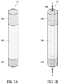
FIGS. 3A and 3B are other diagrams illustrating the stick for an aerosol generating device according to an embodiment. - More specifically,
FIG. 3A illustrates the appearance of thestick 10 for an aerosol generating device according to an embodiment andFIG. 3B illustrates the structure of thestick 10 for an aerosol generating device according to an embodiment. - The
stick 10 for an aerosol generating device according to an embodiment may be mounted to or removed from the aerosol generating device. Referring toFIG. 3A , thestick 10 for an aerosol generating device according to an embodiment may include theinhaler 100, thestorage 200, and theconnector 300. Thestick 10 for an aerosol generating device may be formed to have an overall cylindrical appearance. Each of theinhaler 100, thestorage 200, and theconnector 300 included in thestick 10 for an aerosol generating device may be formed to have a cylinder appearance. Theinhaler 100 may be a portion for the inhalation of a user, and the user may apply inhale pressure to theinhaler 100 to inhale an aerosol. Theinhaler 100 may be formed as a mouthpiece such that the user may inhale easily. Thestorage 200 may store an aerosol forming substrate. An end of thestorage 200 may face and be connected to an end of theinhaler 100. Theconnector 300 may connect thestorage 200 to an atomizer in the aerosol generating device as described below. Theconnector 300 may move the aerosol forming substrate stored in thestorage 200 to the atomizer. Theconnector 300 may include porous materials, such as a cotton wick, a porous ceramic, a paper filter, or the like. Theconnector 300 may move the aerosol forming substrate in thestorage 200 to the atomizer through a capillary phenomenon. Thestorage 200 may be between theinhaler 100 and theconnector 300. - Referring to
FIG. 3B , thestick 10 for an aerosol generating device according to an embodiment may include theinhaler 100, thestorage 200, theconnector 300, and thechannel 400. Thechannel 400 may penetrate and cross the central portions of theinhaler 100, thestorage 200, and theconnector 300. Thechannel 400 may function as an airflow channel through which an aerosol that has atomized in the atomizer moves. The aerosol forming substrate may move from thestorage 200 through theconnector 300 to the atomizer and may be atomized in an aerosol form in the atomizer. As the user inhales theinhaler 100, the atomized aerosol may move, in operation F, through thechannel 400 and may be inhaled by the user. Thechannel 400 may be formed as a cylinder corresponding to the shape of thestick 10 for an aerosol generating device, but the shape and structure of thechannel 400 are not limited to the shape and structure illustrated inFIG. 3 . -
FIG. 4 is another diagram illustrating the aerosol generating device according to an embodiment. - Referring to
FIG. 4 , theaerosol generating device 1, according to an embodiment, may include thestick 10 for an aerosol generating device, thepower 500, thehousing 600, and theatomizer 700. Thestick 10 for an aerosol generating device may be mounted to or removed from the aerosol generating device. Thestick 10 for an aerosol generating device may include theinhaler 100, thestorage 200, theconnector 300, and thechannel 400. Theatomizer 700 may atomize an aerosol forming substrate by using a surface acoustic wave. Theatomizer 700 may receive the aerosol forming substrate from thestorage 200. - The
atomizer 700 may include a surface acousticwave generating element 710 configured to generate a surface acoustic wave, asubstrate element 720 to which the surface acoustic wave generated by the surface acousticwave generating element 710 may be transmitted, and achamber element 730 configured to prevent the deviation of an atomized aerosol. - The surface acoustic
wave generating element 710 may generate a surface acoustic wave configured to atomize a liquid. The surface acoustic wave generated by the surface acousticwave generating element 710 may atomize a liquid aerosol forming substrate. The surface acoustic wave generated by the surface acousticwave generating element 710 may be transmitted to thesubstrate element 720. - The surface acoustic
wave generating element 710 may be designed to generate a surface acoustic wave only when the user inhales the aerosol generating device. Theinhaler 100 may include a respiratory sensor (not shown). The respiratory sensor mounted to theinhaler 100 may sense that the user inhales the aerosol generating device and may generate an electrical control signal such that the surface acoustic wave generating element may operate only when the user inhales the aerosol generating device in theatomizer 700. - The
connector 300 of thestick 10 for an aerosol generating device may transmit the aerosol forming substrate stored in thestorage 200 to thesubstrate element 720 of theatomizer 700. The aerosol forming substrate transmitted to thesubstrate element 720 may be atomized in an aerosol form after meeting a surface acoustic wave applied from the surface acousticwave generating element 710. An aerosol generated by the aerosol forming substrate being atomized may be included by thechamber element 730. - An end of the
connector 300 may contact thesubstrate element 720. The shape of a portion where thesubstrate element 720 contacts theconnector 300 may vary, corresponding to the shape of theconnector 300 of which the central portion is penetrated by thechannel 400. Theconnector 300 may include porous materials, such as a cotton wick, a porous ceramic, a paper filter, or the like. Theconnector 300 may move the aerosol forming substrate in thestorage 200 to the atomizer through a capillary phenomenon. Alternatively, the connector may include a passage element (not shown) configured to move the aerosol forming substrate to thesubstrate element 720 and a control element (not shown) configured to control a rate of flow of the aerosol forming substrate that moves. - The control element (not shown) may control, for example, a rate of flow of moving liquid by controlling the speed of the moving liquid. The control element (not shown) may be a micro pump. The control element (not shown) may supply the aerosol forming substrate to the
substrate element 720 at a preset speed. A control element (not shown) may control a rate of flow of the liquid aerosol forming substrate supplied to thesubstrate unit 720 to control an atomization amount of an aerosol generated in theatomizer 700. - The
channel 400 of thestick 10 for an aerosol generating device may communicate with thechamber element 730. As the user inhales theinhaler 100, an aerosol inside thechamber element 730 may be inhaled, in operation F, by the user along thechannel 400. - The
power 500 may supply power to another member of theaerosol generating device 1 or theatomizer 700 as needed. - The
housing 600 may surround theatomizer 700, thepower 500, and thestick 10 for an aerosol generating device to protect them against external shocks or other external disturbances and may form the appearance of theaerosol generating device 1. Thehousing 600 may include a mechanical structure for easily mounting or removing thestick 10 for an aerosol generating device. -
FIG. 5 is yet another diagram illustrating the aerosol generating device according to an embodiment. - Referring to
FIG. 5 , the aerosol generating device, 1 according to an embodiment, may include thestick 10 for an aerosol generating device, thepower 500, thehousing 600, and theatomizer 700. Thestick 10 for an aerosol generating device may include theinhaler 100, thestorage 200, and theconnector 300. Thepower 500 may be at a part inside thehousing 600. Thepower 500 may be in a position opposite to thestorage 200 with respect to theatomizer 700. -
FIG. 6 is still another diagram illustrating the aerosol generating device according to an embodiment. - Referring to
FIG. 6 , theaerosol generating device 1, according to an embodiment, may include theinhaler 100, thestorage 200, theconnector 300, thepower 500, thehousing 600, and theatomizer 700. Theatomizer 700 may include a surface acousticwave generating element 710 configured to generate a surface acoustic wave, asubstrate element 720 to which the surface acoustic wave generated by the surface acousticwave generating element 710 may be transmitted, and achamber element 730 configured to prevent the deviation of an atomized aerosol. - The
inhaler 100, theconnector 300, thepower 500, thehousing 600, and theatomizer 700 may be formed integrally. Thestorage 200 may be mounted to or removed from thehousing 500. When thestorage 200 is mounted to thehousing 500, theconnector 300 may transmit the aerosol forming substrate stored in thestorage 200 to thesubstrate element 720 of theatomizer 700. In this case, thestorage 200 may desirably store the aerosol forming substrate of 0.5 ml to 1 ml. The user may inhale the aerosol generating device until all the aerosol forming substrate stored in thestorage 200 is exhausted. When all the aerosol forming substrate stored in thestorage 200 is exhausted, the user may remove thestorage 200 from theaerosol generating device 1. -
FIG. 7 is a block diagram illustrating anaerosol generating device 900 according to another embodiment. - The
aerosol generating device 900 may include acontroller 910, asensing unit 920, anoutput unit 930, abattery 940, aheater 950, a user input unit 960, amemory 970, and acommunication unit 980. However, the internal structure of theaerosol generating device 900 is not limited to the internal structure illustrated inFIG. 7 . It is to be understood by those having ordinary skill in the art to which the disclosure pertains that some of the components shown inFIG. 7 may be omitted or new components may be added according to the design of theaerosol generating device 900. - The
sensing unit 920 may sense a state of theaerosol generating device 900 or a state of an environment around theaerosol generating device 900 and may transmit sensing information obtained through the sensing to thecontroller 910. Based on the sensing information, thecontroller 910 may control theaerosol generating device 900 to control operations of theheater 950, may restrict smoking, may determine whether an aerosol generating article (e.g., a cigarette, a cartridge, etc.) is inserted, may display a notification, and may perform other functions. - The
sensing unit 920 may include at least one of atemperature sensor 922, aninsertion detection sensor 924, or apuff sensor 926. However, embodiments are not limited thereto. - The
temperature sensor 922 may sense a temperature at which the heater 950 (or an aerosol generating material) is heated. Theaerosol generating device 900 may include a separate temperature sensor for sensing a temperature of theheater 950, or theheater 950 itself may perform a function as a temperature sensor. Alternatively, thetemperature sensor 922 may be arranged around thebattery 940 to monitor the temperature of thebattery 940. - The
insertion detection sensor 924 may sense whether the aerosol generating article is inserted or removed. Theinsertion detection sensor 924 may include, for example, at least one of a film sensor, a pressure sensor, a light sensor, a resistive sensor, a capacitive sensor, an inductive sensor, or an infrared sensor, which may sense a signal change by the insertion or removal of the aerosol generating article. - The
puff sensor 926 may sense a puff from a user based on various physical changes in an airflow path or airflow channel. For example, thepuff sensor 926 may sense the puff of the user based on any one of a temperature change, a flow change, a voltage change, and a pressure change. - The sensing unit 9120 may further include at least one of a temperature/humidity sensor, an atmospheric pressure sensor, a magnetic sensor, an acceleration sensor, a gyroscope sensor, a position sensor (e.g., a global positioning system (GPS)), a proximity sensor, or a red, green, blue (RGB) sensor (e.g., an illuminance sensor), in addition to the
sensors 922 through 926 described above. In addition, a function of each sensor may be intuitively inferable from its name by one of ordinary skill in the art, and thus, a detailed description thereof will be omitted herein. - The
output unit 930 may output information about the state of theaerosol generating device 900 and provide the information to the user. Theoutput unit 930 may include at least one of adisplay 932, ahaptic portion 934, or asound outputter 936. However, embodiments are not limited thereto. When thedisplay 932 and a touchpad are provided in a layered structure to form a touchscreen, thedisplay 932 may be used as an input device in addition to an output device. - The
display 932 may visually provide the information about theaerosol generating device 900 to the user. The information about theaerosol generating device 900 may include, for example, a charging/discharging state of thebattery 940 of theaerosol generating device 900, a preheating state of theheater 950, an insertion/removal state of the aerosol generating article, a limited usage state (e.g., an abnormal article detected) of theaerosol generating device 900, or the like, and the display 931 may externally output the information. Thedisplay 932 may be, for example, a liquid-crystal display (LCD) panel, an organic light-emitting display (OLED) panel, or the like. Thedisplay 932 may also be in the form of a light-emitting diode (LED) device. - The
haptic portion 934 may provide the information about theaerosol generating device 900 to the user in a haptic way by converting an electrical signal into a mechanical stimulus or an electrical stimulus. Thehaptic portion 934 may include, for example, a motor, a piezoelectric element, or an electrical stimulation device. - The
sound outputter 936 may provide the information about theaerosol generating device 900 to the user in an auditory way. For example, thesound outputter 936 may convert an electric signal into a sound signal and externally output the sound signal. - The
battery 940 may supply power to be used to operate theaerosol generating device 900. Thebattery 940 may supply power to heat theheater 950. In addition, thebattery 940 may supply power required for operations of the other components (e.g., theoutput unit 920, theoutput unit 930, the user input unit 960, thememory 970, and the communication unit 980) included in theaerosol generating device 900. Thebattery 940 may be a rechargeable battery or a disposable battery. Thebattery 940 may be, for example, a lithium polymer (LiPoly) battery, but examples are not limited thereto. - The
heater 950 may receive power from thebattery 940 to heat the aerosol generating material. Although not shown inFIG. 7 , theaerosol generating device 900 may further include a power conversion circuit (e.g., a direct current (DC)-to-DC (DC/DC) converter) that converts power of thebattery 940 and supplies the power to theheater 950. In addition, when theaerosol generating device 900 generates an aerosol in an induction heating manner, theaerosol generating device 900 may further include a DC-to-alternating current (AC) (DC/AC) converter that converts DC power of thebattery 940 into AC power. - The
controller 910, thesensing unit 920, theoutput unit 930, the user input unit 960, thememory 970, and thecontroller 910 may receive power from thebattery 940 to perform functions. Although not shown inFIG. 6 , theaerosol generating device 900 may further include a power conversion circuit, for example, a low dropout (LDO) circuit or a voltage regulator circuit, which converts power of thebattery 940 and supplies the power to respective components. - In an embodiment, the
heater 950 may be formed of a predetermined electrically resistive material that is suitable. For example, the electrically resistive material may be a metal or a metal alloy including, for example, titanium, zirconium, tantalum, platinum, nickel, cobalt, chromium, hafnium, niobium, molybdenum, tungsten, tin, gallium, manganese, iron, copper, stainless steel, nichrome, or the like. However, embodiments are not limited thereto. In addition, the heater 130 may be implemented as a metal heating wire, a metal heating plate on which an electrically conductive track is arranged, a ceramic heating element, or the like. However, embodiments are not limited thereto. - In another embodiment, the
heater 950 may be an induction heater. For example, theheater 950 may include a susceptor that heats an aerosol generating material by generating heat through a magnetic field applied by a coil. - In an embodiment, the
heater 950 may include a plurality of heaters. For example, theheater 950 may include a first heater for heating a cigarette, and a second heater for heating a liquid. - The user input unit 960 may receive information input from a user or may output information to the user. For example, the user input unit 960 may include a keypad, a dome switch, a touchpad (e.g., a contact capacitive type, a pressure resistive film type, an infrared sensing type, a surface ultrasonic conduction type, an integral tension measurement type, a piezo effect method, etc.), a jog wheel, a jog switch, or the like, but examples are not limited thereto. In addition, although not shown in
FIG. 6 , theaerosol generating device 900 may further include a connection interface, such as a USB interface, and may be connected to another external device through the connection interface, such as a USB interface, to transmit and receive information or to charge thebattery 940. - The
memory 970, which is hardware for storing various pieces of data processed in theaerosol generating device 900, may store data processed by thecontroller 910 and data to be processed thereby. Thememory 970 may include at least one type of storage medium of a flash memory type memory, a hard disk type memory, a multimedia card micro type memory, a card type memory (e.g., an SD or XE memory), a random access memory (RAM), a static RAM (SRAM), a read-only memory (ROM), an electrically erasable programmable ROM (EEPROM), a programmable ROM (PROM), a magnetic memory, a magnetic disk, or an optical disk. Thememory 970 may store an operating time of theaerosol generating device 900, a maximum number of puffs, a current number of puffs, at least one temperature profile, data associated with a smoking pattern of the user, or the like. - The
communication unit 980 may include at least one component to communicate with another electronic device. For example, thecommunication unit 980 may include a short-rangewireless communication unit 982 and awireless communication unit 984. - The short-range
wireless communication unit 982 may include a Bluetooth communication unit, a Bluetooth low energy (BLE) communication unit, a near field communication unit, a WLAN (Wi-Fi) communication unit, a ZigBee communication unit, an infrared data association (IrDA) communication unit, a Wi-Fi direct (WFD) communication unit, an ultra-wideband (UWB) communication unit, and an Ant+ communication unit. However, embodiments are not limited thereto. - The
wireless communication unit 984 may include, for example, a cellular network communicator, an Internet communicator, a computer network (e.g., a local area network (LAN) or a wide-area network (WAN)) communicator, or the like. However, embodiments are not limited thereto. Thewireless communication unit 984 may use subscriber information (e.g., international mobile subscriber identity (IMSI)) to identify and authenticate theaerosol generating device 900 in a communication network. - The
controller 910 may control the overall operation of theaerosol generating device 900. In an embodiment, thecontroller 910 may include at least one processor. The processor may be implemented as an array of a plurality of logic gates or may be implemented as a combination of a general-purpose microprocessor and a memory in which a program executable by the microprocessor is stored. In addition, it is to be understood by one of ordinary skill in the art to which the present disclosure pertains that it may be implemented in other types of hardware. - The
controller 910 may control the temperature of theheater 950 by controlling the supply of power from thebattery 940 to theheater 950. For example, thecontroller 910 may control the supply of power by controlling the switching of a switch element between thebattery 940 and theheater 950. In another example, a direct heating circuit may control the supply of power to theheater 950 according to a control command from thecontroller 910. - The
controller 910 may analyze a sensing result obtained by the sensing of thesensing unit 920 and control processes to be performed thereafter. For example, thecontroller 910 may control power to be supplied to theheater 950 to start or end an operation of theheater 950 based on the sensing result obtained by thesensing unit 920. In another example, thecontroller 910 may control an amount of power to be supplied to theheater 950 and a time for which the power is to be supplied, such that theheater 950 may be heated up to a predetermined temperature or maintained at a desired temperature, based on the sensing result obtained by thesensing unit 920. - The
controller 910 may control theoutput unit 930 based on the sensing result obtained by thesensing unit 920. For example, when a number of puffs counted through thepuff sensor 926 reaches a preset number, thecontroller 910 may inform the user that theaerosol generating device 900 is to be ended soon, through at least one of thedisplay 932, thehaptic portion 934, or thesound outputter 936. - According to an embodiment, the
controller 910 may control a power supply time and/or a power supply amount for theheater 950 according to a state of the aerosol generating article sensed by thesensing unit 920. For example, when an aerosol generating article 15 is in an over-humidified state, thecontroller 910 may control the power supply time for an inductive coil to increase a preheating time, compared to a case where the aerosol generating article 15 is in a general state. - One embodiment may also be implemented in the form of a recording medium including instructions executable by a computer, such as a program module executable by the computer. A computer-readable medium may be any available medium that can be accessed by a computer and includes all of a volatile medium, a non-volatile medium, a removable medium, and a non-removable medium. In addition, the computer-readable medium may include both a computer storage medium and a communication medium. The computer storage medium includes all of a volatile medium, a non-volatile medium, a removable medium, and a non-removable medium implemented by any method or technology for storage of information such as computer-readable instructions, data structures, program modules or other data. The communication medium typically includes computer-readable instructions, data structures, other data in modulated data signals such as program modules, or other transmission mechanisms, and includes any information transfer medium.
- As described above, the embodiment has been described with reference to specific matters such as specific components and limited embodiments and drawings, but these are provided to help the overall understanding. Also, the present disclosure is not limited to the above-described embodiments, and various modifications and variations are possible from these descriptions by those skilled in the art to which the present disclosure pertains. Accordingly, the scope of the present disclosure is defined not by the detailed description, but by the claims and their equivalents, and all variations within the scope of the claims and their equivalents are to be construed as being included in the disclosure.
Claims (13)
- An aerosol generating device comprising:an inhaler through which a user inhales an aerosol;a storage configured to store an aerosol forming substrate;an atomizer configured to atomize the aerosol forming substrate by using a surface acoustic wave;a connector configured to connect the storage to the atomizer and transmit the aerosol forming substrate from the storage to the atomizer; anda channel that crosses at least some of the inhaler, the storage, and the connector and through which the atomized aerosol forming substrate moves.
- The aerosol generating device of claim 1, wherein the inhaler, the storage, the connector, and the channel are formed integrally and configured to be separated from or combined with the aerosol generating device.
- The aerosol generating device of claim 1 or 2, wherein the atomizer comprises a surface acoustic wave generating element configured to generate a surface acoustic wave, a substrate element to which the generated surface acoustic wave is transmitted, and a chamber element configured to prevent the deviation of the atomized aerosol forming substrate.
- The aerosol generating device of claim 3, wherein an end of the channel communicates with the chamber element.
- The aerosol generating device of claim 1, wherein the inhaler, the atomizer, and the connector are formed integrally, and the storage is configured to be separated from or combined with the aerosol generating device.
- The aerosol generating device of claim 3, wherein the connector is configured to transmit the aerosol forming substrate stored in the storage to the atomizer through a capillary phenomenon.
- The aerosol generating device of claim 6, wherein an end of the connector contacts the substrate element, and the connector comprises a passage element configured to move the aerosol forming substrate to the substrate element and a control element configured to control a rate of flow of the aerosol forming substrate that moves.
- The aerosol generating device of claim 5, further comprising a power configured to supply power to the atomizer, and the inhaler comprises a respiratory sensor, and the atomizer is connected to the respiratory sensor such that the generation of a surface acoustic wave is adjusted.
- A stick for an aerosol generating device, the stick comprising:an inhaler through which a user inhales an aerosol;a storage configured to store an aerosol forming substrate;a connector configured to move the aerosol forming substrate stored in the storage; anda channel that crosses at least some of the inhaler, the storage, and the connector and through which an aerosol moves.
- The stick of claim 9, wherein the storage is between the inhaler and the connector.
- The stick of claim 10, wherein the channel is formed through a central portion of the inhaler, the storage, and the connector.
- The stick of claim 11, wherein the inhaler, the storage, and the connector are formed as a cylinder.
- The stick of claim 10, wherein the channel is formed to contact a side surface of the inhaler, the storage, and the connector.
Applications Claiming Priority (2)
| Application Number | Priority Date | Filing Date | Title |
|---|---|---|---|
| KR1020220115675A KR102771330B1 (en) | 2022-09-14 | 2022-09-14 | Aerosol generating device |
| PCT/KR2023/007589 WO2024058344A1 (en) | 2022-09-14 | 2023-06-02 | Aerosol generation apparatus |
Publications (2)
| Publication Number | Publication Date |
|---|---|
| EP4516133A1 true EP4516133A1 (en) | 2025-03-05 |
| EP4516133A4 EP4516133A4 (en) | 2025-10-15 |
Family
ID=90275469
Family Applications (1)
| Application Number | Title | Priority Date | Filing Date |
|---|---|---|---|
| EP23865648.2A Pending EP4516133A4 (en) | 2022-09-14 | 2023-06-02 | AEROSOL-GENERATING DEVICE |
Country Status (5)
| Country | Link |
|---|---|
| EP (1) | EP4516133A4 (en) |
| JP (1) | JP2025518123A (en) |
| KR (1) | KR102771330B1 (en) |
| CN (1) | CN119365090A (en) |
| WO (1) | WO2024058344A1 (en) |
Family Cites Families (15)
| Publication number | Priority date | Publication date | Assignee | Title |
|---|---|---|---|---|
| KR101823585B1 (en) | 2011-07-01 | 2018-01-31 | 에스케이바이오랜드 주식회사 | Methods for preparing fermented ginseng extracts |
| EP2753200B1 (en) * | 2011-09-06 | 2017-12-27 | British American Tobacco (Investments) Limited | Heating smokeable material |
| US10617150B2 (en) * | 2015-05-14 | 2020-04-14 | Lunatech, Llc | Vaporization method and apparatus |
| CN105559151B (en) * | 2016-03-21 | 2019-05-24 | 湖南中烟工业有限责任公司 | A kind of ultrasonic ultrasonic delay line memory and electronic cigarette |
| UA125292C2 (en) * | 2016-03-30 | 2022-02-16 | Філіп Морріс Продактс С.А. | Smoking device and method for aerosol-generation |
| CN105962421B (en) * | 2016-07-01 | 2018-12-25 | 林光榕 | Using the electronic smoke atomizer of ultrasonic atomization unit |
| JP6737949B2 (en) * | 2016-08-04 | 2020-08-12 | チャイナ タバコ フーナン インダストリアル カンパニー リミテッド | Disposable cigarette cartridge, atomizer and electronic cigarette |
| WO2019198162A1 (en) * | 2018-04-10 | 2019-10-17 | 日本たばこ産業株式会社 | Atomization unit |
| US12115306B2 (en) * | 2018-04-17 | 2024-10-15 | Philip Morris Products S.A. | Aerosol-generating device having a chamber for receiving a removalbe liquid container |
| US12396480B2 (en) * | 2019-05-22 | 2025-08-26 | Rai Strategic Holdings, Inc. | Reservoir configuration for aerosol delivery device |
| KR20220119440A (en) * | 2019-12-23 | 2022-08-29 | 필립모리스 프로덕츠 에스.에이. | an aerosol generator comprising a plurality of nebulizers |
| CN111165886B (en) * | 2020-02-26 | 2024-07-05 | 云南中烟工业有限责任公司 | A variable frequency surface acoustic wave electronic cigarette |
| KR102533744B1 (en) * | 2020-06-04 | 2023-05-18 | 주식회사 케이티앤지 | Airflow path structure and aerosol generating device comprising same |
| US12185752B2 (en) * | 2020-07-21 | 2025-01-07 | Rai Strategic Holdings, Inc. | Case for aerosol generation device |
| CN114176259B (en) * | 2021-12-06 | 2025-05-16 | 深圳麦克韦尔科技有限公司 | An electronic atomization device and its atomizer and atomization core |
-
2022
- 2022-09-14 KR KR1020220115675A patent/KR102771330B1/en active Active
-
2023
- 2023-06-02 CN CN202380046405.6A patent/CN119365090A/en active Pending
- 2023-06-02 WO PCT/KR2023/007589 patent/WO2024058344A1/en not_active Ceased
- 2023-06-02 JP JP2024569874A patent/JP2025518123A/en active Pending
- 2023-06-02 EP EP23865648.2A patent/EP4516133A4/en active Pending
Also Published As
| Publication number | Publication date |
|---|---|
| KR20240036973A (en) | 2024-03-21 |
| EP4516133A4 (en) | 2025-10-15 |
| WO2024058344A1 (en) | 2024-03-21 |
| KR102771330B1 (en) | 2025-02-26 |
| CN119365090A (en) | 2025-01-24 |
| JP2025518123A (en) | 2025-06-12 |
Similar Documents
| Publication | Publication Date | Title |
|---|---|---|
| US20240215652A1 (en) | Aerosol generating device for controlling power supply to heater and operating method thereof | |
| KR20230068948A (en) | Aerosol generating device and operating method thereof | |
| US20240245128A1 (en) | Aerosol generating device with support providing air to aerosol generating article | |
| KR20230173564A (en) | Aerosol generating device | |
| EP4497334A1 (en) | Aerosol generating device | |
| JP7750994B2 (en) | Aerosol generating device and method of operation thereof | |
| KR102771330B1 (en) | Aerosol generating device | |
| JP2025538648A (en) | Aerosol generating device and aerosol generating system including the same | |
| US20240423268A1 (en) | Aerosol generating device | |
| US20260130420A1 (en) | Aerosol generating device | |
| KR102816644B1 (en) | Device and method for generating aerosol | |
| US20260130421A1 (en) | Aerosol-generating device | |
| US12561054B2 (en) | Method and apparatus for unlocking based on user input | |
| US20250072498A1 (en) | Vaporizer for aerosol generating device and aerosol generating device including the same | |
| KR102815643B1 (en) | Inhaler | |
| US20240251861A1 (en) | Aerosol generating device | |
| KR20240108193A (en) | Case for aerosol generating device and aerosol generating system including the same | |
| JP2026506138A (en) | Aerosol generating device, aerosol generating system, and aerosol generating method | |
| KR20260034469A (en) | Aerosol generating device | |
| JP2026514373A (en) | Battery coupling structure and aerosol generating apparatus containing the same | |
| JP2026511716A (en) | Aerosol generator | |
| JP2026513198A (en) | Aerosol generator | |
| KR20250018923A (en) | Battery assembly structure and aerosol generating device comprising the same | |
| KR20250019553A (en) | Aerosol generating device | |
| KR20250023237A (en) | Aerosol generating device |
Legal Events
| Date | Code | Title | Description |
|---|---|---|---|
| STAA | Information on the status of an ep patent application or granted ep patent |
Free format text: STATUS: THE INTERNATIONAL PUBLICATION HAS BEEN MADE |
|
| PUAI | Public reference made under article 153(3) epc to a published international application that has entered the european phase |
Free format text: ORIGINAL CODE: 0009012 |
|
| STAA | Information on the status of an ep patent application or granted ep patent |
Free format text: STATUS: REQUEST FOR EXAMINATION WAS MADE |
|
| 17P | Request for examination filed |
Effective date: 20241128 |
|
| AK | Designated contracting states |
Kind code of ref document: A1 Designated state(s): AL AT BE BG CH CY CZ DE DK EE ES FI FR GB GR HR HU IE IS IT LI LT LU LV MC ME MK MT NL NO PL PT RO RS SE SI SK SM TR |
|
| A4 | Supplementary search report drawn up and despatched |
Effective date: 20250917 |
|
| RIC1 | Information provided on ipc code assigned before grant |
Ipc: A24F 40/05 20200101AFI20250911BHEP Ipc: A24F 40/40 20200101ALI20250911BHEP Ipc: A24F 40/44 20200101ALI20250911BHEP Ipc: A24F 40/50 20200101ALI20250911BHEP Ipc: A24F 40/51 20200101ALI20250911BHEP Ipc: A24C 5/18 20060101ALI20250911BHEP Ipc: A24D 3/02 20060101ALI20250911BHEP Ipc: A24F 40/20 20200101ALI20250911BHEP |
|
| DAV | Request for validation of the european patent (deleted) | ||
| DAX | Request for extension of the european patent (deleted) |