EP4514001A1 - Instruction for start of artificial intelligence and/or machine learning to terminal device by base station device - Google Patents
Instruction for start of artificial intelligence and/or machine learning to terminal device by base station device Download PDFInfo
- Publication number
- EP4514001A1 EP4514001A1 EP22938408.6A EP22938408A EP4514001A1 EP 4514001 A1 EP4514001 A1 EP 4514001A1 EP 22938408 A EP22938408 A EP 22938408A EP 4514001 A1 EP4514001 A1 EP 4514001A1
- Authority
- EP
- European Patent Office
- Prior art keywords
- training
- terminal device
- base station
- slot
- instructing
- Prior art date
- Legal status (The legal status is an assumption and is not a legal conclusion. Google has not performed a legal analysis and makes no representation as to the accuracy of the status listed.)
- Pending
Links
Images



Classifications
-
- H—ELECTRICITY
- H04—ELECTRIC COMMUNICATION TECHNIQUE
- H04W—WIRELESS COMMUNICATION NETWORKS
- H04W72/00—Local resource management
- H04W72/20—Control channels or signalling for resource management
- H04W72/23—Control channels or signalling for resource management in the downlink direction of a wireless link, i.e. towards a terminal
- H04W72/232—Control channels or signalling for resource management in the downlink direction of a wireless link, i.e. towards a terminal the control data signalling from the physical layer, e.g. DCI signalling
-
- G—PHYSICS
- G06—COMPUTING OR CALCULATING; COUNTING
- G06F—ELECTRIC DIGITAL DATA PROCESSING
- G06F16/00—Information retrieval; Database structures therefor; File system structures therefor
- G06F16/90—Details of database functions independent of the retrieved data types
- G06F16/903—Querying
-
- G—PHYSICS
- G06—COMPUTING OR CALCULATING; COUNTING
- G06N—COMPUTING ARRANGEMENTS BASED ON SPECIFIC COMPUTATIONAL MODELS
- G06N20/00—Machine learning
-
- H—ELECTRICITY
- H04—ELECTRIC COMMUNICATION TECHNIQUE
- H04W—WIRELESS COMMUNICATION NETWORKS
- H04W72/00—Local resource management
- H04W72/04—Wireless resource allocation
-
- H—ELECTRICITY
- H04—ELECTRIC COMMUNICATION TECHNIQUE
- H04W—WIRELESS COMMUNICATION NETWORKS
- H04W72/00—Local resource management
- H04W72/04—Wireless resource allocation
- H04W72/044—Wireless resource allocation based on the type of the allocated resource
- H04W72/0446—Resources in time domain, e.g. slots or frames
-
- H—ELECTRICITY
- H04—ELECTRIC COMMUNICATION TECHNIQUE
- H04W—WIRELESS COMMUNICATION NETWORKS
- H04W72/00—Local resource management
- H04W72/04—Wireless resource allocation
- H04W72/11—Semi-persistent scheduling
Definitions
- the present disclosure relates to an instruction from a base station apparatus causing a terminal device to start artificial intelligence and/or machine learning.
- the 4th generation mobile communication system (4G) is also referred to as Long Term Evolution, or LTE
- the 5th generation mobile communication system (5G) is also referred to as New Radio Access Technology, or NR.
- LTE and NR have been discussed in the 3rd Generation Partnership Project (3GPP), and standardization have been studied.
- a base station apparatus may have one or more cells.
- a plurality of cells may exist in a range of a radio wave emitted by the base station apparatus.
- Communication in one or a plurality of the cells may be referred to as cellular communication.
- a terminal device and the base station apparatus may transmit and receive data by using the cellular communication.
- enhanced mobile broadband evolved from highspeed and high-capacity (mobile broadband) data communication in a mobile communication system of the related art
- URLLC ultra reliable and low latency communications
- mMTC massive machine type communications
- An object of the present disclosure is to provide a method in which a base station apparatus instructs a terminal device to start artificial intelligence and/or machine learning.
- a base station apparatus instructs a terminal device to start artificial intelligence and/or machine learning.
- it is considered to perform channel estimation by using artificial intelligence and/or machine learning in the terminal device and/or the base station apparatus.
- a base station apparatus characterized in that the base station apparatus signals the terminal device to start the artificial intelligence and/or the machine learning, a terminal device, a method of being implemented by the base station apparatus, or a method of being implemented by the terminal device is not known.
- the communication can be efficiently performed between the base station apparatus and the terminal device.
- a terminal device may be a device that communicates with a base station apparatus.
- the terminal device may be referred to as a user equipment (UE).
- the base station apparatus may be referred to as a base station.
- the base station apparatus In LTE, the base station apparatus is referred to as an evolved NodeB (eNodeB) or an eNB. In NR, the base station apparatus is referred to as a gNodeB or a gNB.
- eNodeB evolved NodeB
- gNodeB gNodeB
- the downlink may include a frequency, a signal, and/or data, which is emitted from the base station apparatus toward the terminal device.
- a communication method in the downlink may be a wireless communication method.
- the uplink may include a frequency, a signal, and/or data, which is emitted from the terminal device toward the base station apparatus.
- a communication method in the uplink may be a wireless communication method.
- the base station apparatus 1 may configure one or both of a master cell group (MCG) and/or a secondary cell group (SCG).
- MCG master cell group
- SCG secondary cell group
- the SCG may be configured as one or more SCGs, or may not be configured.
- the MCG includes at least a primary cell (PCell).
- PCell primary cell
- PSCell primary secondary cell
- the base station apparatus 1 may provide configuration parameters to the MCG included in a higher layer parameter CellGroupConfig.
- the base station apparatus 1 may provide configuration parameters to the SCG included in the higher layer parameter CellGroupConfig.
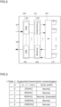
- FIG. 2 is an example of a conceptual block diagram illustrating a configuration of the terminal device 1 according to the present embodiment.
- a block 200 is a higher layer processing unit.
- a block 201 is a baseband signal processing unit that processes a baseband signal.
- a block 202 is an RF unit that up-converts a baseband signal into a carrier.
- Reference numerals 209, 210, 211, and 212 denote antennas that transmit and/or receive a radio wave.
- the medium access controller 203 may perform medium access control (MAC).
- the medium access controller 203 may be a protocol existing in the terminal device 1 and the base station apparatus 1.
- the medium access controller 203 may map a logical channel and a transport channel.
- the medium access controller 203 may perform logical channel multiplexing.
- the medium access controller 203 may handle Hybrid Automatic Repeat reQuest (HARQ).
- HARQ Hybrid Automatic Repeat reQuest
- the media access controller may perform processing for a MAC layer.
- the higher layer processing unit 200 processes and manages configuration information regarding transmission and reception, the configuration information being received from the base station apparatus 1.
- the configuration information is referred to as a higher layer parameter.
- the higher layer parameter may include at least a medium access control control element (MAC CE) and a radio resource control parameter (RRC parameter).
- MAC CE medium access control control element
- RRC parameter radio resource control parameter
- the higher layer parameter may be a higher layer signalling.
- Fig. 3 is a diagram illustrating an example of a relationship between a supportable numerology and the cyclic prefix in the present embodiment.
- ⁇ is zero
- the subcarrier spacing is 15 kHz
- the length of the cyclic prefix may be Normal.
- the subcarrier spacing is 30 kHz
- the length of the cyclic prefix may be Normal.
- the terminal device 1 may configure the length of the Cyclic Prefix to Extended.
- N slot subframe, ⁇ may represent the number of slots included in one subframe for the configuration ⁇ of the SCS.
- N slot frame, ⁇ may represent the number of slots included in one frame for the configuration ⁇ of the SCS.
- One subframe may be 1 ms regardless of the value of the SCS.
- the number N slot subframe, ⁇ of slots included in one subframe may be one.
- the number N slot subframe, ⁇ of slots included in one subframe may be two.
- the number N slot subframe, ⁇ of slots included in one subframe may be four.
- the number N slot subframe, ⁇ of slots included in one subframe may be eight.
- the number N slot subframe, ⁇ of slots included in one subframe may be 16.
- a bandwidth N grid, x size, ⁇ of the carrier in the SCS configuration ⁇ may be given by carrierBandwidth included in a higher layer parameter SCS-SpecificCarrier.
- x included in N grid, x size, ⁇ may be downlink (DL), uplink (UL), or sidelink (SL).
- a starting position N grid start, ⁇ of the resource grid in the SCS configuration ⁇ may be given by offsetToCarrier included in the higher layer parameter SCS-SpecificCarrier.
- a frequency location of a subcarrier may refer to a center frequency of the subcarrier. That is, when a frequency interval between the subcarriers is calculated, the frequency interval may be calculated using the interval between the center frequencies of the subcarriers.
- Each element included in the resource grid in the SCS configuration ⁇ and an antenna port p may be referred to as a resource element (RE).
- the resource element may be identified by (k, l) p, ⁇ .
- k may be an index in a frequency domain.
- l may represent a symbol position with respect to a reference point in a time domain.
- the symbol may be an OFDM symbol.
- the resource elements (k, l) p, ⁇ may correspond to a physical resource and a complex number a k, l (p, ⁇ ) .
- the symbol may mean the OFDM symbol.
- Scheduling may mean that the base station apparatus 1 secures a resource the terminal device 1 uses to transmit and/or receive a physical signal.
- the base station apparatus 1 may schedule four PRBs of a reference numeral 503 included in symbol #0, symbol #1, and symbol #2 in Fig. 5 to the terminal device 1. That is, the resource secured (scheduled) for the terminal device 1 to receive the PDSCH may be an area where symbol #0, symbol #1, symbol #2, and the reference numeral 503 intersect.
- scheduling means to schedule In the present embodiment, it can also be said that scheduling means to schedule.
- a and B are transmitted at the same time may mean that A and B are transmitted at the same time in one or more same OFDM symbols in a slot.
- Point A may serve as a common reference point of the resource grid.
- the resource grid may be a resource block grid.
- Point A may be given based on a higher layer parameter offsetToPointA.
- Point A may be given based on a higher layer parameter absoluteFrequencyPointA.
- CRBs may be numbered in an increasing order from zero in the frequency domain.
- a lower-numbered CRB may be located in a lower frequency domain.
- CRB #n may be located in a frequency domain lower than CRB #n+1.
- the nth CRB is also referred to as CRB #n.
- the center of subcarrier #0 included in CRB #0 may be Point A.
- n CRB ⁇ floor (k/N SC RB ).
- floor (x1) is a function that outputs the greatest integer among integers identical to or smaller than x1. For example, an output of floor (1.2) is one. An output of floor (2.99) is two. An output of floor (3) is three.
- the PRB may be defined in a bandwidth part (BWP). That is, a physical resource block configuring the BWP may be a PRB.
- BWP bandwidth part
- the base station apparatus 1 may configure reference numeral 503 as the BWP in the terminal device 1.
- the PRBs may be numbered (or indexed) from zero to (N BWP, i size, ⁇ -1).
- the index of the PRB including the lowest frequency among the PRBs included in a BWP may be zero
- the index of the PRB including the highest frequency may be N BWP, i size, ⁇ -1
- the index of the PRB between PRB #0 and PRB #N BWP, i size, ⁇ -1 may be given in an increasing order.
- N BWP, i size, ⁇ may be the number of PRBs configuring the BWP in the SCS configuration ⁇ .
- the nth PRB is also referred to as PRB #n.
- the BWP may be a subset of consecutive CRBs for a numerology ⁇ i set in the ith BWP in a component carrier.
- the BWP may include one or more consecutive CRBs.
- the BWP may include one or more consecutive PRBs.
- the BWP in the downlink may be referred to as a downlink BWP (DL BWP).
- the maximum four DL BWPs may be configured in the downlink for the terminal device 1. Among the maximum four DL BWPs, one DL BWP may be activated at a certain time.
- the terminal device 1 may not be expected to receive PDSCH, PDCCH, or CSI-RS outside the range of the activated DL BWP.
- the terminal device 1 may be expected to receive PDSCH, PDCCH, or CSI-RS in RB included in the activated DL BWP.
- the BWP in the uplink may be referred to as an uplink BWP (UL BWP).
- the maximum four UL BWPs may be configured in the uplink for the terminal device 1. Among the maximum four UL BWPs, one UL BWP may be activated at a certain time.
- the terminal device 1 may not transmit PUSCH or PUCCH outside the range of the activated UL BWP.
- the terminal device 1 may transmit PUSCH or PUCCH in RB included in the activated UL BWP. In an activated cell, the terminal device 1 may not transmit the SRS outside the range of the activated BWP.
- the transport channel may be a channel that transfers information between a physical layer and the MAC layer.
- a downlink transport channel may include at least a broadcast channel (BCH), a downlink shared channel (DL-SCH), a paging channel (PCH), an uplink shared channel (UL-SCH), a random access channel (RACH), a sidelink broadcast channel (SL-BCH), and a sidelink shared channel (SL-SCH).
- BCH broadcast channel
- DL-SCH downlink shared channel
- PCH paging channel
- UL-SCH uplink shared channel
- RACH random access channel
- SL-BCH sidelink broadcast channel
- SL-SCH sidelink shared channel
- the BCH may be used in a case where a single message or a BCH instance that differs depending on beamforming is broadcast to all the areas of a cell.
- the size of the BCH may be fixed.
- the BCH may use a pre-defined format.
- the DL-SCH may be used to transmit user data, control information, higher layer parameters, or DL system information.
- the DL-SCH may support HARQ.
- the DL-SCH may support dynamic link adaptation by changing a modulation scheme, coding, transmission power, and the like.
- the DL-SCH may be broadcast to all the cells.
- the DL-SCH may use beamforming.
- the DL-SCH may support dynamic and/or semi-static resource allocation.
- the PCH may support discontinuous reception (DRX) that enables power saving of the terminal device 1 (UE power saving).
- DRX discontinuous reception
- the PCH may be used in a case where a single message or a BCH instance that differs depending on beamforming are broadcast to all the areas of a cell.
- the base station apparatus 1 may transmit a physical broadcast channel (PBCH) including a master information block (MIB) to the terminal device 1 in the downlink.
- PBCH physical broadcast channel
- MIB master information block
- the physical downlink control channel may be used to schedule downlink transmission (DL transmission) on the physical downlink shared channel (PDSCH), or may be used to schedule uplink transmission (UL transmission) on the physical uplink shared channel (PUSCH).
- the PDCCH may include downlink control information (DCI).
- the PDSCH may be a physical channel that carries the DL-SCH.
- the DL-SCH may be coded.
- the PDSCH may be used to transmit one or two transport blocks (TB).
- PDSCH transmission may be assigned together with a reference signal in which the DCI included in the PDCCH includes DMRS.
- the PDSCH may be decoded based on at least information included in the PDCCH. That is, the time and frequency domain resources for the PDSCH, the modulation scheme, and the number of layers may be determined based on at least information included in the PDCCH.
- the PDSCH transmission may be performed by using two or more and 14 or less OFDM symbols.
- the number of layers for the PDSCH transmission may be eight or less.
- HARQ feedback or retransmission may be supported.
- the terminal device 1 may transmit Preamble to the base station apparatus 1 by using a physical random access channel (PRACH).
- PRACH physical random access channel
- 64 Preambles may be defined.
- the PRACH occasion may be defined by the time domain and the frequency domain.
- the length of Preamble may include at least four different lengths.
- the Preamble may be referred to as PRACH preamble.
- the PRACH preamble may have one or more PRACH formats.
- Each of the PRACH formats may have one or more PRACH preamble sequences.
- Each of the PRACH formats may be defined in one or more PRACH OFDM symbols.
- Each of the PRACH formats may be defined with a different CP length and/or a different guard time.
- the configuration of the PRACH preamble may be provided to the terminal device 1 through system information.
- the PUCCH may be used to carry uplink control information (UCI).
- UCI uplink control information
- the UCI may include some or all of Hybrid Automatic Repeat reQuest-ACKnowledgement (HARQ-ACK) information, a scheduling request (SR), and/or channel state information (CSI).
- HARQ-ACK Hybrid Automatic Repeat reQuest-ACKnowledgement
- SR scheduling request
- CSI channel state information
- the UCI may be carried on the PUCCH or the PUSCH.
- a scheme of channel coding may be different depending on the number of bits of the UCI.
- a PUCCH resource set including one or more PUCCH resources may be configured.
- One PUCCH resource may be determined based on at least a UCI payload size and a PUCCH resource indicator (PRI) field included in DL Assignment.
- PRI PUCCH resource indicator
- one or more pieces of UCI included in a plurality of the PUCCHs may be multiplexed into one PUCCH.
- the UCI included in the PUCCH may be multiplexed into the PUSCH.
- the PUCCH resource may be a resource for transmitting the UCI in the time domain and/or frequency domain.
- the PUCCH resource may be configured in a PUCCH format.
- a PUCCH format 0 may be used to transmit UCI of two bits or less by using one or two OFDM symbols.
- a PUCCH format 1 may be used to transmit UCI of two bits or less by using four or more and 14 or less OFDM symbols.
- a PUCCH format 2 may be used to transmit UCI greater than two bits by using one or two OFDM symbols.
- a PUCCH format 3 may be used to transmit UCI greater than two bits by using four or more and 14 or less OFDM symbols.
- a PUCCH format 4 may be used to transmit UCI greater than two bits by using four or more and 14 or less OFDM symbols.
- the PUSCH may be a physical channel that carries the UL-SCH.
- the PUSCH may be a physical channel that carries the UCI.
- the PUSCH may be used to transmit one transport block (TB).
- PUSCH transmission may be scheduled together with a reference signal in which the DCI included in the PDCCH includes DMRS.
- the PUSCH may be decoded based on at least information included in the PDCCH. That is, the time and frequency domain resources for the PUSCH, the modulation scheme, and the number of layers may be determined based on at least information included in the PDCCH.
- the number of layers for the PDSCH transmission may be four or less.
- HARQ retransmission may be supported.
- the DMRS may be used to measure a state of a communication channel.
- the DMRS may be a signal different for each user. Note that information for specifying the user may be included when the DMRS is generated.
- the DMRS may be transmitted simultaneously with the PUCCH.
- the DMRS may be transmitted simultaneously with the PUSCH.
- the DMRS may be transmitted simultaneously with the PDSCH.
- the DMRS may be transmitted simultaneously with the PDCCH.
- the DMRS may be transmitted simultaneously with the PBCH.
- the PTRS may be used to measure a phase noise in the communication channel.
- the PTRS may be transmitted simultaneously with the PUSCH.
- the PTRS may be transmitted simultaneously with the PDSCH.
- the PTRS may be associated with one DMRS port.
- the SRS may be different for each terminal device (UE-specific).
- the SRS may be transmitted using one OFDM symbol, two OFDM symbols, or four OFDM symbols, which is consecutive in a slot.
- a positioning reference signal may be transmitted simultaneously with the PDSCH, may be transmitted simultaneously with the PDCCH, or may be transmitted simultaneously with any of the transmission channels in the downlink.
- One or more downlink PRS positioning frequency layers may be configured for one terminal device 1.
- the PRS positioning frequency layer may be configured by one or more PRS resource sets.
- the PRS resource set may be configured by one or more PRS resources.
- the CSI-RS may be transmitted in the downlink.
- One or more CSI reports corresponding to a CSI-RS may be configured.
- a plurality of the terminal devices may share one CSI-RS.
- the resource for the CSI-RS in the time domain may be configured in any OFDM symbol in one slot.
- the resource for the CSI-RS in the time domain may be configured in one OFDM symbol, two OFDM symbols, or four OFDM symbols.
- the CSI-RS may be configured with 32 antenna ports.
- the base station apparatus 1 may transmit the CSI-RS to the terminal device 1 periodically, semi-persistently, or aperiodically.
- Channel estimation in the terminal device 1 may be performed based on at least a reference signal transmitted from the base station apparatus 1.
- the reference signal transmitted from the base station apparatus 1 may be a demodulation reference signal (DMRS), a PTRS, a CSI-RS, or an SSB.
- DMRS demodulation reference signal
- PTRS PTRS
- CSI-RS CSI-RS
- SSB SSB
- the reference signal is a known signal which a transmitter and a receiver recognize. That is, the receiver may be capable of recognizing in advance what reference signal is transmitted from the transmitter.
- Channel estimation in the base station apparatus 1 may be performed based on at least a reference signal transmitted from the terminal device 1.
- the reference signal transmitted from the terminal device 1 may be a demodulation reference signal (DMRS), a PTRS, or an SRS.
- DMRS demodulation reference signal
- PTRS PTRS
- SRS SRS
- the reference signals transmitted from the base station apparatus 1 and the terminal device 1 may be expressed in a form of a complex number that is a combination of a real number and an imaginary number. For example, in a case where the reference signal to be transmitted is 1 + 2j and the reference signal is received through the communication channel, the reference signal is set to 0.5 + 2j.
- the receiver installed in the base station apparatus 1 and/or the terminal device 1 compares the transmitted reference signal with the received reference signal in the time domain and/or the frequency band to estimate channel information, and then perform correction processing on the received signal based on the estimation result of the channel information.
- the imaginary number may be a number which is the same as or smaller than zero when a certain number is multiplied by the number itself. That is, the imaginary number may be a negative number obtained when a certain number is multiplied by the number itself.
- B is the imaginary number.
- X ⁇ Y means that X is smaller than Y.
- j may be added to the imaginary number.
- 2j may be an imaginary number.
- 2j x 2j may be -4.
- the base station apparatus 1 and/or the terminal device 1 may perform channel estimation by using a channel model.
- the base station apparatus 1 and/or the terminal device 1 may assist the channel estimation by using the channel model.
- the base station apparatus 1 and/or the terminal device 1 may perform positioning by using the channel model.
- the base station apparatus 1 and/or the terminal device 1 may assist positioning by using the channel model.
- the base station apparatus 1 and/or the terminal device 1 may perform the channel estimation by using artificial intelligence and/or machine learning (AI/ML).
- AI/ML artificial intelligence and/or machine learning
- the base station apparatus 1 and/or the terminal device 1 may assist the channel estimation by using the AI/ML.
- the base station apparatus 1 and/or the terminal device 1 may perform positioning by using the AI/ML.
- the base station apparatus 1 and/or the terminal device 1 may assist positioning by using the AI/ML.
- the channel model may be created using the AI/ML.
- the channel model may be created by performing training.
- the artificial intelligence may be capability of a device, such as the base station apparatus 1 and/or the terminal device 1, which determines and/or analyzes a situation by itself.
- the machine learning may be used to find a pattern of data collected by the base station apparatus 1 and/or the terminal device 1 based on the collected data.
- the base station apparatus 1 may instruct the terminal device 1 to perform training for the AI/ML.
- the base station apparatus 1 may trigger the terminal device 1 to perform training for the AI/ML.
- instructing training for the AI/ML is also defined as instructing training or triggering training.
- the base station apparatus 1 may instruct the terminal device 1 to perform training by using a higher layer parameter trainingType.
- the trainingType may be configured as aperiodic, semi-persistent, periodic, or instantaneous.
- the base station apparatus 1 may trigger the terminal device 1 to perform training by using the DCI. In a case where the higher layer parameter trainingType is configured as aperiodic, the base station apparatus 1 may trigger the terminal device 1 to perform training by using a field included in the DCI. In a case where the higher layer parameter trainingType is configured as aperiodic, the terminal device 1 may start training from X slot slot number, or from a slot number configured with a higher layer parameter trainingSlotOffset, with reference to the slot in which the PDCCH including the DCI is received.
- X slot may be an integer that is the same as or greater than zero. For example, in a case where the X slot is zero, the terminal device 1 may start training from the slot in which the PDCCH including the DCI is received.
- the terminal device 1 may perform training among X duration slots including the slot in which the training is started.
- X duration may be an integer that is the same as or greater than zero.
- the terminal device 1 may perform the training during a time of three slots including the slot in which the training is started.
- the terminal device 1 may perform training in the slot numbers configured with the higher layer parameter trainingDuration.
- the slot numbers may include the slot in which the training is started.
- Fig. 6 is a diagram illustrating an example of a training method in a case where the higher layer parameter trainingType is configured as aperiodic in the present embodiment.
- the terminal device 1 receives PDCCH 601 including DCI 602 from the base station apparatus 1.
- the DCI 602 has information for instructing the start of training.
- a higher layer parameter trainingType 603 is configured as aperiodic.
- a higher layer parameter trainingSlotOffset 604 is configured as two.
- a higher layer parameter trainingDuration 605 is configured as four. Since two is configured by trainingSlotOffset 604, the terminal device 1 may start training in Slot #n+2 which is after two slots from a slot Slot #n which has received the PDCCH 601. Furthermore, in the training duration, since trainingDuration 605 is configured as four, the training may be performed in four slots. That is, in Fig. 6 , the terminal device 1 may perform training from Slot #n+2 to Slot #n+5.
- the base station apparatus 1 may trigger the terminal device 1 to perform training by using the DCI. In a case where the higher layer parameter trainingType is configured as semi-persistent, the base station apparatus 1 may trigger the terminal device 1 to perform training by using a field included in the DCI. In a case where the higher layer parameter trainingType is configured as semi-persistent, the terminal device 1 may start training from X slot slot, or from a slot number configured with a higher layer parameter trainingSlotOffset, with reference to the slot in which the PDCCH including the DCI is received.
- X slot may be an integer that is the same as or greater than zero. For example, in a case where the X slot is zero, the terminal device 1 may start training from the slot in which the PDCCH including the DCI is received.
- the terminal device 1 may perform training based on a training period provided by the higher layer parameter trainingPeriod and a training duration provided by the higher layer parameter trainingDuration.
- the training period may be indicated in units of slot, units of symbol, or units of frame.
- the training period may be a value representing a time.
- the training duration may be indicated in units of slot, units of symbol, or units of frame.
- the training duration may be a value representing a time.
- the base station apparatus 1 may instruct the terminal device 1 to end training by using the DCI. In a case where the higher layer parameter trainingType is configured as semi-persistent, the base station apparatus 1 may instruct the terminal device 1 to end training by using a field included in the DCI. In a case where the higher layer parameter trainingType is configured as semi-persistent, the terminal device 1 may end training from X slotFinish slot, or from a slot number configured with a higher layer parameter trainingFinishSlotOffset, with reference to the slot in which the PDCCH including the DCI is received.
- X slotFinish may be an integer that is the same as or greater than zero. For example, in a case where the X slotFinish is zero, the terminal device 1 may end training from the slot in which the PDCCH including the DCI is received.
- Fig. 7 is a diagram illustrating an example of a training method in a case where the higher layer parameter trainingType is configured as semi-persistent in the present embodiment.
- the terminal device 1 receives PDCCH 701 including DCI 702 from the base station apparatus 1.
- the DCI 702 has information for instructing the start of training.
- a higher layer parameter trainingType 703 is configured as semi-persistent.
- a higher layer parameter trainingSlotOffset 704 is configured as one.
- a higher layer parameter trainingDuration 705 is configured as one. Since one is configured by trainingSlotOffset 704, the terminal device 1 may start training in Slot #n+1 which is after one slot from a slot Slot #n which has received the PDCCH 701.
- the training since trainingDuration is configured as one, the training may be performed in one slot. That is, in Fig. 7 , the terminal device 1 may perform training in Slot #n+1. Note that since a higher layer parameter trainingPeriod 706 is configured by two, the terminal device 1 may perform training with two slots as a period, based on trainingDuration 705. That is, the terminal device 1 may perform training in Slot #n+3.
- the terminal device 1 receives PDCCH 709 including DCI 710 instructing the end of training through Slot #n+4.
- the DCI 710 has information for instructing the end of training.
- a higher layer parameter trainingFinishSlotOffset is configured as one. Since one is configured by trainingFinishSlotOffset, the terminal device 1 may end training in Slot #n+5 which is after one slot from a slot Slot #n+4 which has received the PDCCH 709.
- the terminal device 1 may start training from when RRC is connected. In a case where the higher layer parameter trainingType is configured as periodic, the terminal device 1 may start training from X slot slot number, or from a slot number configured with a higher layer parameter trainingSlotOffset, with reference to the slot when the RRC is connected.
- X slot may be an integer that is the same as or greater than zero. For example, in a case where the X slot is zero, the terminal device 1 may start training from the slot when the RRC is connected.
- the terminal device 1 may perform training based on a training period provided by the higher layer parameter trainingPeriod and a training duration provided by the higher layer parameter trainingDuration.
- the training period may be indicated in units of slot, units of symbol, or units of frame.
- the training period may be a value representing a time.
- the training duration may be indicated in units of slot, units of symbol, or units of frame.
- the training duration may be a value representing a time.
- Fig. 8 is a diagram illustrating an example of a training method in a case where the higher layer parameter trainingType is configured as periodic in the present embodiment.
- RRC is in a connected state.
- a higher layer parameter trainingType 802 is configured as periodic.
- a higher layer parameter trainingSlotOffset 803 is configured as one.
- a higher layer parameter trainingDuration 804 is configured as one. Since one is configured by trainingSlotOffset 803, the terminal device 1 may start training in Slot #n+1 which is after one slot from a slot Slot #n which has received the PDCCH 701. Furthermore, in the training duration, since trainingDuration 804 is configured as one, the training may be performed in one slot. That is, the terminal device 1 may perform training in Slot #n+1.
- the terminal device 1 may perform training with two slots as a period, based on trainingDuration 804. That is, in Fig. 8 , the terminal device 1 may perform training in Slot #n+3, Slot #n+5, and Slot #n+2*x1+1.
- * may be a multiplication.
- x1 may be a value configured as trainingPeriod.
- the trigger counter may be counted based on the number of NACKs transmitted from the terminal device 1 to the base station apparatus 1 in a HARQ process related to the PDSCH received by the terminal device 1.
- the trigger counter may be counted based on initial transmission and/or retransmission of the PDSCH.
- the trigger counter may be counted based on a new data indicator (NDI).
- NDI new data indicator
- RV redundancy version
- the terminal device 1 may perform training based on the training duration provided by the higher layer parameter trainingDuration.
- the training period may be indicated in units of slot, units of symbol, or units of frame.
- the training period may be a value representing a time.
- the training duration may be indicated in units of slot, units of symbol, or units of frame.
- the training duration may be a value representing a time.
- Fig. 9 is a diagram illustrating an example of a training method in a case where the higher layer parameter trainingType is configured as instantaneous in the present embodiment.
- An initial value of the trigger counter may be zero.
- a higher layer parameter trainingType 902 is configured as instantaneous.
- a higher layer parameter trainingFinishSlotOffset 903 is configured as one.
- a higher layer parameter trainingDuration 904 is configured as five.
- a higher layer parameter trainingThreshold 905 is configured as ten.
- a trigger counter 901 is counted to reach ten
- one is configured by trainingSlotOffset 903 and thus the terminal device 1 may start training in Slot #n+1 which is after one slot from a slot Slot #n in which the trigger counter 901 reaches ten.
- the trigger counter When training is started, the trigger counter may be reset to zero. Furthermore, in the training duration, since trainingDuration 904 is configured as five, the training may be performed in five slots. That is, in Fig. 9 , the terminal device 1 may perform training from Slot #n+1 to Slot #n+5.
- a program that is operated in the base station apparatus 1 and the terminal device 1 according to an aspect of the present disclosure may control a central processing unit (CPU) or the like so as to implement functions of the above-described embodiments according to an aspect of the present disclosure.
- CPU central processing unit
- the present disclosure relates to an instruction from a base station apparatus causing a terminal device to start artificial intelligence and/or machine learning.
- terminal device 1 terminal device 1A, terminal device 1B, terminal device 1C
- 200 higher layer processing unit 201 baseband processing unit
Landscapes
- Engineering & Computer Science (AREA)
- Theoretical Computer Science (AREA)
- Software Systems (AREA)
- Signal Processing (AREA)
- Computer Networks & Wireless Communication (AREA)
- General Engineering & Computer Science (AREA)
- Data Mining & Analysis (AREA)
- Physics & Mathematics (AREA)
- General Physics & Mathematics (AREA)
- Evolutionary Computation (AREA)
- Computing Systems (AREA)
- Mathematical Physics (AREA)
- Medical Informatics (AREA)
- Computer Vision & Pattern Recognition (AREA)
- Artificial Intelligence (AREA)
- Databases & Information Systems (AREA)
- Computational Linguistics (AREA)
- Mobile Radio Communication Systems (AREA)
Abstract
Description
- The present disclosure relates to an instruction from a base station apparatus causing a terminal device to start artificial intelligence and/or machine learning.
- The 4th generation mobile communication system (4G) is also referred to as Long Term Evolution, or LTE, and the 5th generation mobile communication system (5G) is also referred to as New Radio Access Technology, or NR. LTE and NR have been discussed in the 3rd Generation Partnership Project (3GPP), and standardization have been studied.
- A base station apparatus may have one or more cells. A plurality of cells may exist in a range of a radio wave emitted by the base station apparatus. Communication in one or a plurality of the cells may be referred to as cellular communication. A terminal device and the base station apparatus may transmit and receive data by using the cellular communication.
- In the 5th generation mobile communication system, enhanced mobile broadband (eMBB) evolved from highspeed and high-capacity (mobile broadband) data communication in a mobile communication system of the related art, ultra reliable and low latency communications (URLLC), and massive machine type communications (mMTC) are adopted.
- An object of the present disclosure is to provide a method in which a base station apparatus instructs a terminal device to start artificial intelligence and/or machine learning. In 3GPP, it is considered to perform channel estimation by using artificial intelligence and/or machine learning in the terminal device and/or the base station apparatus. However, a base station apparatus characterized in that the base station apparatus signals the terminal device to start the artificial intelligence and/or the machine learning, a terminal device, a method of being implemented by the base station apparatus, or a method of being implemented by the terminal device is not known.
-
- (1) In order to achieve the above-described object, aspects of the present disclosure take the following measures. That is, according to a first aspect of the present disclosure, there is provided a terminal device including: a reception unit that receives a signal for instructing start of training; and a transmission unit that transmits training data, in which the signal for instructing the start of the training includes a training start timing and a training period, and in a case where the signal for instructing the start of the training is received, the training data is generated based on the training start timing and the training period.
- (2) According to a second aspect of the present disclosure, there is provided a base station apparatus including: a transmission unit that transmits a signal for instructing start of training; and a reception unit that receives training data, in which the signal for instructing the start of the training includes a training start timing and a training period, and in a case where the signal for instructing the start of the training is transmitted, the training data is instructed to be generated based on the training start timing and the training period.
- (3) According to a third aspect of the present disclosure, there is provided a communication method used in a terminal device, in which a processing unit that processes a signal for instructing start of training and a processing unit that processes training data are provided, the signal for instructing the start of the training includes a training start timing and a training period, and in a case where the signal for instructing the start of the training is received, the training data is generated based on the training start timing and the training period.
- (4) According to a fourth aspect of the present disclosure, there is provided a communication method used in a base station apparatus, in which a processing unit that processes a signal for instructing start of training and a processing unit that processes training data are provided, the signal for instructing the start of the training includes a training start timing and a training period, and in a case where the signal for instructing the start of the training is transmitted, the training data is instructed to be generated based on the training start timing and the training period.
- According to the present disclosure, the communication can be efficiently performed between the base station apparatus and the terminal device.
-
-
Fig. 1 is a diagram illustrating an example in which a terminal device and a base station apparatus according to the present embodiment perform communication. -
Fig. 2 is an example of a conceptual block diagram illustrating a configuration of aterminal device 1 according to the present embodiment. -
Fig. 3 is a diagram illustrating an example of a relationship between a supportable numerology and a cyclic prefix in the present embodiment. -
Fig. 4 is a diagram illustrating a relationship among SCS, a slot, a frame, and a subframe according to the present embodiment. -
Fig. 5 is a diagram illustrating an example of a resource grid according to the present embodiment. -
Fig. 6 is a diagram illustrating an example of a training method in a case where a higher layer parameter trainingType is configured as aperiodic in the present embodiment. -
Fig. 7 is a diagram illustrating an example of a training method in a case where a higher layer parameter trainingType is configured as semi-persistent in the present embodiment. -
Fig. 8 is a diagram illustrating an example of a training method in a case where a higher layer parameter trainingType is configured as periodic in the present embodiment. -
Fig. 9 is a diagram illustrating an example of a training method in a case where a higher layer parameter trainingType is configured as instantaneous in the present embodiment. - A terminal device may be a device that communicates with a base station apparatus. The terminal device may be referred to as a user equipment (UE). The base station apparatus may be referred to as a base station.
- In LTE, the base station apparatus is referred to as an evolved NodeB (eNodeB) or an eNB. In NR, the base station apparatus is referred to as a gNodeB or a gNB.
- Communication from the base station apparatus toward the terminal device may be referred to as downlink. The downlink may include a frequency, a signal, and/or data, which is emitted from the base station apparatus toward the terminal device. A communication method in the downlink may be a wireless communication method.
- Communication from the terminal device toward the base station apparatus may be referred to as uplink. The uplink may include a frequency, a signal, and/or data, which is emitted from the terminal device toward the base station apparatus. A communication method in the uplink may be a wireless communication method.
-
Fig. 1 is a diagram illustrating an example in which the terminal device and the base station apparatus according to the present embodiment perform communication. Abase station apparatus 100 and abase station apparatus 101 may be referred to as abase station apparatus 1 or a base station apparatus. Aterminal device 102, aterminal device 103, and aterminal device 104 may be referred to as aterminal device 1 or a terminal device.Reference numerals base station apparatus 1 to theterminal device 1 may denote downlink.Reference numerals terminal device 1 to thebase station apparatus 1 may be uplink. - The
base station apparatus 1 may configure one or both of a master cell group (MCG) and/or a secondary cell group (SCG). The SCG may be configured as one or more SCGs, or may not be configured. The MCG includes at least a primary cell (PCell). The SCG includes at least a primary secondary cell (PSCell). - The
base station apparatus 1 may provide configuration parameters to the MCG included in a higher layer parameter CellGroupConfig. Thebase station apparatus 1 may provide configuration parameters to the SCG included in the higher layer parameter CellGroupConfig. -
Fig. 2 is an example of a conceptual block diagram illustrating a configuration of theterminal device 1 according to the present embodiment. Ablock 200 is a higher layer processing unit. Ablock 201 is a baseband signal processing unit that processes a baseband signal. Ablock 202 is an RF unit that up-converts a baseband signal into a carrier.Reference numerals - The higher
layer processing unit 200 may include amedium access controller 203 and aradio resource controller 204. - The
medium access controller 203 may perform medium access control (MAC). Themedium access controller 203 may be a protocol existing in theterminal device 1 and thebase station apparatus 1. Themedium access controller 203 may map a logical channel and a transport channel. Themedium access controller 203 may perform logical channel multiplexing. Themedium access controller 203 may handle Hybrid Automatic Repeat reQuest (HARQ). The media access controller may perform processing for a MAC layer. - The
radio resource controller 204 may perform radio resource control (RRC). Theradio resource controller 204 may perform management for broadcast information, management for paging, RRC connection control, security handling, radio bearer management, mobility management, management for Quality Of Service (QOS), and the like. Theradio resource controller 204 may perform processing for an RRC layer. - The higher
layer processing unit 200 processes and manages configuration information regarding transmission and reception, the configuration information being received from thebase station apparatus 1. The configuration information is referred to as a higher layer parameter. The higher layer parameter may include at least a medium access control control element (MAC CE) and a radio resource control parameter (RRC parameter). Furthermore, the higher layer parameter may be a higher layer signalling. - A subcarrier spacing (SCS) may be adjusted to µ. A configuration parameter of the subcarrier spacing may be referred to as µ. The subcarrier spacing (Δf) may have a relationship of Δf = 2µ × 15 kHz. In a case where there are a plurality of configuration parameters µ of the subcarrier spacing, it may mean that the subcarrier spacing has a plurality of numerologies.
- A cyclic prefix (CP) may be a guard interval provided to correct multipath interference caused by to latency in a channel. The cyclic prefix may have a different length in accordance with a channel state. A higher layer parameter cyclicPrefix may indicate whether or not to use an extended cyclic prefix in a certain bandwidth part (BWP). The
base station apparatus 1 may indicate a length of the cyclic prefix to theterminal device 1 with the higher layer parameter cyclicPrefix. Theterminal device 1 may configure the length of the cyclic prefix in accordance with a value of the higher layer parameter cyclicPrefix. The length of the cyclic prefix may be defined by Normal and Extended. The length of the Extended cyclic prefix may be longer than the length of the Normal cyclic prefix. -
Fig. 3 is a diagram illustrating an example of a relationship between a supportable numerology and the cyclic prefix in the present embodiment. In a case where µ is zero, the subcarrier spacing is 15 kHz, and the length of the cyclic prefix may be Normal. In a case where µ is one, the subcarrier spacing is 30 kHz, and the length of the cyclic prefix may be Normal. In a case where µ is two, the subcarrier spacing is 60 kHz, and the length of the cyclic prefix may be Normal or Extended. In a case where µ is set to two and the higher layer parameter cyclicPrefix is set to Extended, theterminal device 1 may configure the length of the Cyclic Prefix to Extended. In a case where µ is set to two and the higher layer parameter cyclicPrefix is not set, theterminal device 1 may configure the length of the Cyclic Prefix to Normal. In a case where µ is three, the subcarrier spacing is 120 kHz, and the length of the cyclic prefix may be Normal. In a case where µ is four, the subcarrier spacing is 240 kHz, and the length of the cyclic prefix may be Normal. 1 kHz is 1000 Hz. - For the configuration µ of the SCS, one or more slots may be numbered in an increasing order in one subframe. That is, a slot number ns µ may have a relationship of ns µ = {0, ···, Nslot subframe, µ-1}. Here, Nslot subframe, µ may represent the number of slots included in one subframe for the configuration µ of the SCS. For the configuration µ of the SCS, one or more slots may be numbered in an increasing order in one frame. That is, slot numbers ns, f
µ may have a relationship of ns, f µ = {0, ···, Nslot frame, µ-1}. Here, Nslot frame, µ may represent the number of slots included in one frame for the configuration µ of the SCS. -
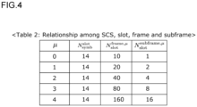
Fig. 4 is a diagram illustrating a relationship among the SCS, the slot, the frame, and the subframe according to the present embodiment. One slot may include Nsymb slot symbols. The number Nsymb slot of slots included in one slot may differ depending on the type of CP. In a case where the CP is configured as Normal, Nsymb slot may be 14 regardless of a value of the SCS. In a case where the CP is configured as Extended, Nsymb slot may be 12. - The duration of one frame may be 10 ms regardless of the SCS. 1 ms is 1/1000 seconds. The number of slots included in one frame may differ depending on the SCS. For example, in a case where the SCS is 15 kHz (µ = 0), the number Nslot frame, µ of slots included in one frame may be 10. Furthermore, in a case where the SCS is 30 kHz (µ = 1), the number Nslot frame, µ of slots included in one frame may be 20. Furthermore, in a case where the SCS is 60 kHz (µ = 2), the number Nslot frame, µ of slots included in one frame may be 40. Furthermore, in a case where the SCS is 120 kHz (µ = 3), the number Nslot frame, µ of slots included in one frame may be 80. Furthermore, in a case where the SCS is 240 kHz (µ = 4), the number Nslot frame, µ of slots included in one frame may be 160.
- One subframe may be 1 ms regardless of the value of the SCS. For example, in a case where the SCS is 15 kHz (µ = 0), the number Nslot subframe, µ of slots included in one subframe may be one. Furthermore, in a case where the SCS is 30 kHz (µ = 1), the number Nslot subframe, µ of slots included in one subframe may be two. Furthermore, in a case where the SCS is 60 kHz (µ = 2), the number Nslot subframe, µ of slots included in one subframe may be four. Furthermore, in a case where the SCS is 120 kHz (µ = 3), the number Nslot subframe, µ of slots included in one subframe may be eight. Furthermore, in a case where the SCS is 240 kHz (µ = 4), the number Nslot subframe, µ of slots included in one subframe may be 16.
- For a numerology and a carrier, a resource grid with Ngrid, x size, µ × Nsc RB subcarriers and Nsymb subframe, µ OFDM symbols may be defined. The resource grid may start from a common resource block (CRB) Ngrid start, µ . Ngrid start, µ may be indicated from a higher layer parameter. There may be one set of resource grids for each transmission direction. The transmission direction may be an uplink direction, a downlink direction, or a sidelink direction.
- For the uplink and the downlink, a bandwidth Ngrid, x size, µ of the carrier in the SCS configuration µ may be given by carrierBandwidth included in a higher layer parameter SCS-SpecificCarrier. x included in Ngrid, xsize, µ may be downlink (DL), uplink (UL), or sidelink (SL).
- A starting position Ngrid start, µ of the resource grid in the SCS configuration µ may be given by offsetToCarrier included in the higher layer parameter SCS-SpecificCarrier. A frequency location of a subcarrier may refer to a center frequency of the subcarrier. That is, when a frequency interval between the subcarriers is calculated, the frequency interval may be calculated using the interval between the center frequencies of the subcarriers.
- Each element included in the resource grid in the SCS configuration µ and an antenna port p may be referred to as a resource element (RE). The resource element may be identified by (k, l)p, µ. Here, k may be an index in a frequency domain. Furthermore, l may represent a symbol position with respect to a reference point in a time domain. The symbol may be an OFDM symbol. The resource elements (k, l)p, µ may correspond to a physical resource and a complex number ak, l (p, µ).
- In the present embodiment, unless otherwise specified, the symbol may mean the OFDM symbol.
- A resource block (RB) may be referred to as a common resource block (CRB) or a physical resource block (PRB). The RB may be defined by the CRB and the PRB. The RB may include the CRB and the PRB. One resource block (RB) may be defined by 12 consecutive subcarriers in the frequency domain. That is, the number of consecutive subcarriers included in one RB may be defined as NSC RB, and may be NSC RB = 12. One CRB may be defined by 12 consecutive subcarriers in the frequency domain.
-
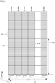
Fig. 5 is a diagram illustrating an example of the resource grid according to the present embodiment. A horizontal axis of the drawing indicates the time domain, and a vertical axis indicates the frequency domain. Areference numeral 500 denotes one subcarrier. Furthermore, areference numeral 501 denotes one PRB including 12 subcarriers. Areference numeral 502 denotes one slot including 14 symbols. - Scheduling may mean that the
base station apparatus 1 secures a resource theterminal device 1 uses to transmit and/or receive a physical signal. For example, in order for theterminal device 1 to receive PDSCH transmitted from thebase station apparatus 1, thebase station apparatus 1 may schedule four PRBs of areference numeral 503 included insymbol # 0,symbol # 1, andsymbol # 2 inFig. 5 to theterminal device 1. That is, the resource secured (scheduled) for theterminal device 1 to receive the PDSCH may be an area wheresymbol # 0,symbol # 1,symbol # 2, and thereference numeral 503 intersect. - In the present embodiment, it can also be said that scheduling means to schedule.
- Unless otherwise specified in the present disclosure, "A and B are transmitted at the same time" may mean that A and B are transmitted at the same time in one or more same OFDM symbols in a slot.
- Point A may serve as a common reference point of the resource grid. The resource grid may be a resource block grid. Point A may be given based on a higher layer parameter offsetToPointA. Point A may be given based on a higher layer parameter absoluteFrequencyPointA.
- For the SCS configurations µ, CRBs may be numbered in an increasing order from zero in the frequency domain. A lower-numbered CRB may be located in a lower frequency domain. For example, CRB #n may be located in a frequency domain lower than CRB #n+1. In the present embodiment, the nth CRB is also referred to as CRB #n. For the SCS configuration µ, the center of
subcarrier # 0 included inCRB # 0 may be Point A. - In the SCS configuration µ, a relationship between a CRB number nCRB µ and a resource element (k, l) in the frequency domain may be nCRB µ = floor (k/NSC RB). Here, k may be associated with Point A. That is, when k = 0, the center frequency of the subcarrier may be located at Point A. Furthermore, floor (x1) is a function that outputs the greatest integer among integers identical to or smaller than x1. For example, an output of floor (1.2) is one. An output of floor (2.99) is two. An output of floor (3) is three.
- In the SCS configuration µ, the PRB may be defined in a bandwidth part (BWP). That is, a physical resource block configuring the BWP may be a PRB. For example, the
base station apparatus 1 may configurereference numeral 503 as the BWP in theterminal device 1. The PRBs may be numbered (or indexed) from zero to (NBWP, i size, µ-1). That is, the index of the PRB including the lowest frequency among the PRBs included in a BWP may be zero, the index of the PRB including the highest frequency may be NBWP, i size, µ-1, and the index of the PRB betweenPRB # 0 and PRB #NBWP, i size, µ-1 may be given in an increasing order. Here, NBWP, i size, µ may be the number of PRBs configuring the BWP in the SCS configuration µ. In the present embodiment, the nth PRB is also referred to as PRB #n. - The BWP may be a subset of consecutive CRBs for a numerology µi set in the ith BWP in a component carrier. The BWP may include one or more consecutive CRBs. The BWP may include one or more consecutive PRBs.
- The BWP in the downlink may be referred to as a downlink BWP (DL BWP). The maximum four DL BWPs may be configured in the downlink for the
terminal device 1. Among the maximum four DL BWPs, one DL BWP may be activated at a certain time. Theterminal device 1 may not be expected to receive PDSCH, PDCCH, or CSI-RS outside the range of the activated DL BWP. Theterminal device 1 may be expected to receive PDSCH, PDCCH, or CSI-RS in RB included in the activated DL BWP. - The BWP in the uplink may be referred to as an uplink BWP (UL BWP). The maximum four UL BWPs may be configured in the uplink for the
terminal device 1. Among the maximum four UL BWPs, one UL BWP may be activated at a certain time. Theterminal device 1 may not transmit PUSCH or PUCCH outside the range of the activated UL BWP. Theterminal device 1 may transmit PUSCH or PUCCH in RB included in the activated UL BWP. In an activated cell, theterminal device 1 may not transmit the SRS outside the range of the activated BWP. - The transport channel may be a channel that transfers information between a physical layer and the MAC layer. A downlink transport channel may include at least a broadcast channel (BCH), a downlink shared channel (DL-SCH), a paging channel (PCH), an uplink shared channel (UL-SCH), a random access channel (RACH), a sidelink broadcast channel (SL-BCH), and a sidelink shared channel (SL-SCH).
- The BCH may be used in a case where a single message or a BCH instance that differs depending on beamforming is broadcast to all the areas of a cell. The size of the BCH may be fixed. The BCH may use a pre-defined format.
- The DL-SCH may be used to transmit user data, control information, higher layer parameters, or DL system information. The DL-SCH may support HARQ. The DL-SCH may support dynamic link adaptation by changing a modulation scheme, coding, transmission power, and the like. Furthermore, the DL-SCH may be broadcast to all the cells. Furthermore, the DL-SCH may use beamforming. The DL-SCH may support dynamic and/or semi-static resource allocation.
- The PCH may support discontinuous reception (DRX) that enables power saving of the terminal device 1 (UE power saving). The PCH may be used in a case where a single message or a BCH instance that differs depending on beamforming are broadcast to all the areas of a cell.
- The
base station apparatus 1 may transmit a physical broadcast channel (PBCH) including a master information block (MIB) to theterminal device 1 in the downlink. - The physical downlink control channel (PDCCH) may be used to schedule downlink transmission (DL transmission) on the physical downlink shared channel (PDSCH), or may be used to schedule uplink transmission (UL transmission) on the physical uplink shared channel (PUSCH). The PDCCH may include downlink control information (DCI).
- The PDSCH may be a physical channel that carries the DL-SCH. The DL-SCH may be coded. The PDSCH may be used to transmit one or two transport blocks (TB). PDSCH transmission may be assigned together with a reference signal in which the DCI included in the PDCCH includes DMRS. The PDSCH may be decoded based on at least information included in the PDCCH. That is, the time and frequency domain resources for the PDSCH, the modulation scheme, and the number of layers may be determined based on at least information included in the PDCCH. The PDSCH transmission may be performed by using two or more and 14 or less OFDM symbols. The number of layers for the PDSCH transmission may be eight or less. For the PDSCH transmission, HARQ feedback or retransmission may be supported.
- The
terminal device 1 may transmit Preamble to thebase station apparatus 1 by using a physical random access channel (PRACH). In each PRACH occasion, 64 Preambles may be defined. The PRACH occasion may be defined by the time domain and the frequency domain. The length of Preamble may include at least four different lengths. The Preamble may be referred to as PRACH preamble. The PRACH preamble may have one or more PRACH formats. Each of the PRACH formats may have one or more PRACH preamble sequences. Each of the PRACH formats may be defined in one or more PRACH OFDM symbols. Each of the PRACH formats may be defined with a different CP length and/or a different guard time. The configuration of the PRACH preamble may be provided to theterminal device 1 through system information. - The PUCCH may be used to carry uplink control information (UCI).
- The UCI may include some or all of Hybrid Automatic Repeat reQuest-ACKnowledgement (HARQ-ACK) information, a scheduling request (SR), and/or channel state information (CSI). The UCI may be carried on the PUCCH or the PUSCH. A scheme of channel coding may be different depending on the number of bits of the UCI.
- In HARQ-ACK feedback of the PDSCH corresponding to a DCI, a PUCCH resource set including one or more PUCCH resources may be configured. One PUCCH resource may be determined based on at least a UCI payload size and a PUCCH resource indicator (PRI) field included in DL Assignment. In a case where a plurality of the PUCCHs are overlapped in the time domain, one or more pieces of UCI included in a plurality of the PUCCHs may be multiplexed into one PUCCH. In a case where the PUCCH and the PUSCH are overlapped in the time domain, the UCI included in the PUCCH may be multiplexed into the PUSCH.
- The PUCCH resource may be a resource for transmitting the UCI in the time domain and/or frequency domain. The PUCCH resource may be configured in a PUCCH format. A
PUCCH format 0 may be used to transmit UCI of two bits or less by using one or two OFDM symbols. APUCCH format 1 may be used to transmit UCI of two bits or less by using four or more and 14 or less OFDM symbols. APUCCH format 2 may be used to transmit UCI greater than two bits by using one or two OFDM symbols. APUCCH format 3 may be used to transmit UCI greater than two bits by using four or more and 14 or less OFDM symbols. APUCCH format 4 may be used to transmit UCI greater than two bits by using four or more and 14 or less OFDM symbols. - The PUSCH may be a physical channel that carries the UL-SCH. The PUSCH may be a physical channel that carries the UCI. The PUSCH may be used to transmit one transport block (TB). PUSCH transmission may be scheduled together with a reference signal in which the DCI included in the PDCCH includes DMRS. The PUSCH may be decoded based on at least information included in the PDCCH. That is, the time and frequency domain resources for the PUSCH, the modulation scheme, and the number of layers may be determined based on at least information included in the PDCCH. The number of layers for the PDSCH transmission may be four or less. For the PDSCH transmission, HARQ retransmission may be supported.
- The DMRS may be used to measure a state of a communication channel. The DMRS may be a signal different for each user. Note that information for specifying the user may be included when the DMRS is generated. The DMRS may be transmitted simultaneously with the PUCCH. The DMRS may be transmitted simultaneously with the PUSCH. The DMRS may be transmitted simultaneously with the PDSCH. The DMRS may be transmitted simultaneously with the PDCCH. The DMRS may be transmitted simultaneously with the PBCH.
- PTRS may be used to measure a phase noise in the communication channel. The PTRS may be transmitted simultaneously with the PUSCH. The PTRS may be transmitted simultaneously with the PDSCH. The PTRS may be associated with one DMRS port.
- The SRS may be different for each terminal device (UE-specific). The SRS may be transmitted using one OFDM symbol, two OFDM symbols, or four OFDM symbols, which is consecutive in a slot.
- A positioning reference signal (PRS) may be transmitted simultaneously with the PDSCH, may be transmitted simultaneously with the PDCCH, or may be transmitted simultaneously with any of the transmission channels in the downlink. One or more downlink PRS positioning frequency layers may be configured for one
terminal device 1. The PRS positioning frequency layer may be configured by one or more PRS resource sets. The PRS resource set may be configured by one or more PRS resources. - The CSI-RS may be transmitted in the downlink. One or more CSI reports corresponding to a CSI-RS may be configured. A plurality of the terminal devices may share one CSI-RS. The resource for the CSI-RS in the time domain may be configured in any OFDM symbol in one slot. The resource for the CSI-RS in the time domain may be configured in one OFDM symbol, two OFDM symbols, or four OFDM symbols. The CSI-RS may be configured with 32 antenna ports. The
base station apparatus 1 may transmit the CSI-RS to theterminal device 1 periodically, semi-persistently, or aperiodically. - Channel estimation in the
terminal device 1 may be performed based on at least a reference signal transmitted from thebase station apparatus 1. The reference signal transmitted from thebase station apparatus 1 may be a demodulation reference signal (DMRS), a PTRS, a CSI-RS, or an SSB. The reference signal is a known signal which a transmitter and a receiver recognize. That is, the receiver may be capable of recognizing in advance what reference signal is transmitted from the transmitter. - Channel estimation in the
base station apparatus 1 may be performed based on at least a reference signal transmitted from theterminal device 1. The reference signal transmitted from theterminal device 1 may be a demodulation reference signal (DMRS), a PTRS, or an SRS. - An example of the channel estimation will be described. The reference signals transmitted from the
base station apparatus 1 and theterminal device 1 may be expressed in a form of a complex number that is a combination of a real number and an imaginary number. For example, in a case where the reference signal to be transmitted is 1 + 2j and the reference signal is received through the communication channel, the reference signal is set to 0.5 + 2j. The receiver installed in thebase station apparatus 1 and/or theterminal device 1 compares the transmitted reference signal with the received reference signal in the time domain and/or the frequency band to estimate channel information, and then perform correction processing on the received signal based on the estimation result of the channel information. - The real number may be a number which is the same as or greater than zero when a certain number is multiplied by the number itself. That is, the real number may be a positive number including zero when a certain number is multiplied by the number itself. For example, in the result of multiplying a certain number A by the number itself (A x A), when A x A > = 0, A is the real number. Here, X > = Y means that X is the same as or greater than Y. Furthermore, the imaginary number may be a number which is the same as or smaller than zero when a certain number is multiplied by the number itself. That is, the imaginary number may be a negative number obtained when a certain number is multiplied by the number itself. For example, in the result of multiplying a certain number B by the number itself (B x B), when B x B < 0, B is the imaginary number. Here, X < Y means that X is smaller than Y. In order to distinguish between the real number and the imaginary number, j may be added to the imaginary number. For example, 2j may be an imaginary number. Furthermore, 2j x 2j may be -4.
- The
base station apparatus 1 and/or theterminal device 1 may perform channel estimation by using a channel model. Thebase station apparatus 1 and/or theterminal device 1 may assist the channel estimation by using the channel model. Thebase station apparatus 1 and/or theterminal device 1 may perform positioning by using the channel model. Thebase station apparatus 1 and/or theterminal device 1 may assist positioning by using the channel model. - The
base station apparatus 1 and/or theterminal device 1 may perform the channel estimation by using artificial intelligence and/or machine learning (AI/ML). Thebase station apparatus 1 and/or theterminal device 1 may assist the channel estimation by using the AI/ML. Thebase station apparatus 1 and/or theterminal device 1 may perform positioning by using the AI/ML. Thebase station apparatus 1 and/or theterminal device 1 may assist positioning by using the AI/ML. - The channel model may be created using the AI/ML. The channel model may be created by performing training. The artificial intelligence may be capability of a device, such as the
base station apparatus 1 and/or theterminal device 1, which determines and/or analyzes a situation by itself. The machine learning may be used to find a pattern of data collected by thebase station apparatus 1 and/or theterminal device 1 based on the collected data. - The
base station apparatus 1 may instruct theterminal device 1 to perform training for the AI/ML. Thebase station apparatus 1 may trigger theterminal device 1 to perform training for the AI/ML. In the present embodiment, instructing training for the AI/ML is also defined as instructing training or triggering training. - The
base station apparatus 1 may instruct theterminal device 1 to perform training by using a higher layer parameter trainingType. The trainingType may be configured as aperiodic, semi-persistent, periodic, or instantaneous. - In a case where the higher layer parameter trainingType is configured as aperiodic, the
base station apparatus 1 may trigger theterminal device 1 to perform training by using the DCI. In a case where the higher layer parameter trainingType is configured as aperiodic, thebase station apparatus 1 may trigger theterminal device 1 to perform training by using a field included in the DCI. In a case where the higher layer parameter trainingType is configured as aperiodic, theterminal device 1 may start training from Xslot slot number, or from a slot number configured with a higher layer parameter trainingSlotOffset, with reference to the slot in which the PDCCH including the DCI is received. Here, Xslot may be an integer that is the same as or greater than zero. For example, in a case where the Xslot is zero, theterminal device 1 may start training from the slot in which the PDCCH including the DCI is received. - In a case where the higher layer parameter trainingType is configured as aperiodic, the
terminal device 1 may perform training among Xduration slots including the slot in which the training is started. Here, Xduration may be an integer that is the same as or greater than zero. For example, in a case where Xduration is three, theterminal device 1 may perform the training during a time of three slots including the slot in which the training is started. In a case where the higher layer parameter trainingType is configured as aperiodic, theterminal device 1 may perform training in the slot numbers configured with the higher layer parameter trainingDuration. The slot numbers may include the slot in which the training is started. -
Fig. 6 is a diagram illustrating an example of a training method in a case where the higher layer parameter trainingType is configured as aperiodic in the present embodiment. Theterminal device 1 receivesPDCCH 601 includingDCI 602 from thebase station apparatus 1. TheDCI 602 has information for instructing the start of training. A higherlayer parameter trainingType 603 is configured as aperiodic. A higher layer parameter trainingSlotOffset 604 is configured as two. A higher layer parameter trainingDuration 605 is configured as four. Since two is configured by trainingSlotOffset 604, theterminal device 1 may start training in Slot #n+2 which is after two slots from a slot Slot #n which has received thePDCCH 601. Furthermore, in the training duration, since trainingDuration 605 is configured as four, the training may be performed in four slots. That is, inFig. 6 , theterminal device 1 may perform training from Slot #n+2 to Slot #n+5. - In a case where the higher layer parameter trainingType is configured as semi-persistent, the
base station apparatus 1 may trigger theterminal device 1 to perform training by using the DCI. In a case where the higher layer parameter trainingType is configured as semi-persistent, thebase station apparatus 1 may trigger theterminal device 1 to perform training by using a field included in the DCI. In a case where the higher layer parameter trainingType is configured as semi-persistent, theterminal device 1 may start training from Xslot slot, or from a slot number configured with a higher layer parameter trainingSlotOffset, with reference to the slot in which the PDCCH including the DCI is received. Here, Xslot may be an integer that is the same as or greater than zero. For example, in a case where the Xslot is zero, theterminal device 1 may start training from the slot in which the PDCCH including the DCI is received. - In a case where the higher layer parameter trainingType is configured as semi-persistent, the
terminal device 1 may perform training based on a training period provided by the higher layer parameter trainingPeriod and a training duration provided by the higher layer parameter trainingDuration. The training period may be indicated in units of slot, units of symbol, or units of frame. The training period may be a value representing a time. The training duration may be indicated in units of slot, units of symbol, or units of frame. The training duration may be a value representing a time. - In a case where the higher layer parameter trainingType is configured as semi-persistent, the
base station apparatus 1 may instruct theterminal device 1 to end training by using the DCI. In a case where the higher layer parameter trainingType is configured as semi-persistent, thebase station apparatus 1 may instruct theterminal device 1 to end training by using a field included in the DCI. In a case where the higher layer parameter trainingType is configured as semi-persistent, theterminal device 1 may end training from XslotFinish slot, or from a slot number configured with a higher layer parameter trainingFinishSlotOffset, with reference to the slot in which the PDCCH including the DCI is received. Here, XslotFinish may be an integer that is the same as or greater than zero. For example, in a case where the XslotFinish is zero, theterminal device 1 may end training from the slot in which the PDCCH including the DCI is received. -
Fig. 7 is a diagram illustrating an example of a training method in a case where the higher layer parameter trainingType is configured as semi-persistent in the present embodiment. Theterminal device 1 receivesPDCCH 701 includingDCI 702 from thebase station apparatus 1. TheDCI 702 has information for instructing the start of training. A higherlayer parameter trainingType 703 is configured as semi-persistent. A higherlayer parameter trainingSlotOffset 704 is configured as one. A higher layer parameter trainingDuration 705 is configured as one. Since one is configured bytrainingSlotOffset 704, theterminal device 1 may start training in Slot #n+1 which is after one slot from a slot Slot #n which has received thePDCCH 701. Furthermore, in the training duration, since trainingDuration is configured as one, the training may be performed in one slot. That is, inFig. 7 , theterminal device 1 may perform training in Slot #n+1. Note that since a higherlayer parameter trainingPeriod 706 is configured by two, theterminal device 1 may perform training with two slots as a period, based on trainingDuration 705. That is, theterminal device 1 may perform training in Slot #n+3. - The
terminal device 1 receivesPDCCH 709 includingDCI 710 instructing the end of training through Slot #n+4. TheDCI 710 has information for instructing the end of training. A higher layer parameter trainingFinishSlotOffset is configured as one. Since one is configured by trainingFinishSlotOffset, theterminal device 1 may end training in Slot #n+5 which is after one slot from a slot Slot #n+4 which has received thePDCCH 709. - In a case where the higher layer parameter trainingType is configured as periodic, the
terminal device 1 may start training from when RRC is connected. In a case where the higher layer parameter trainingType is configured as periodic, theterminal device 1 may start training from Xslot slot number, or from a slot number configured with a higher layer parameter trainingSlotOffset, with reference to the slot when the RRC is connected. Here, Xslot may be an integer that is the same as or greater than zero. For example, in a case where the Xslot is zero, theterminal device 1 may start training from the slot when the RRC is connected. - In a case where the higher layer parameter trainingType is configured as periodic, the
terminal device 1 may perform training based on a training period provided by the higher layer parameter trainingPeriod and a training duration provided by the higher layer parameter trainingDuration. The training period may be indicated in units of slot, units of symbol, or units of frame. The training period may be a value representing a time. The training duration may be indicated in units of slot, units of symbol, or units of frame. The training duration may be a value representing a time. -
Fig. 8 is a diagram illustrating an example of a training method in a case where the higher layer parameter trainingType is configured as periodic in the present embodiment. In Slot #n, RRC is in a connected state. A higherlayer parameter trainingType 802 is configured as periodic. A higherlayer parameter trainingSlotOffset 803 is configured as one. A higherlayer parameter trainingDuration 804 is configured as one. Since one is configured bytrainingSlotOffset 803, theterminal device 1 may start training in Slot #n+1 which is after one slot from a slot Slot #n which has received thePDCCH 701. Furthermore, in the training duration, sincetrainingDuration 804 is configured as one, the training may be performed in one slot. That is, theterminal device 1 may perform training in Slot #n+1. Note that since a higherlayer parameter trainingPeriod 805 is configured by two, theterminal device 1 may perform training with two slots as a period, based ontrainingDuration 804. That is, inFig. 8 , theterminal device 1 may perform training in Slot #n+3, Slot #n+5, and Slot #n+2*x1+1. Here, * may be a multiplication. x1 may be a value configured as trainingPeriod. - In a case where the higher layer parameter trainingType is configured as instantaneous, the
terminal device 1 may start training based on a trigger counter. That is, when a value of the trigger counter is the same as or greater than a threshold Xthreadshold, theterminal device 1 may start training. The threshold Xthreadshold may be an integer greater than zero, or may be given as a higher layer parameter trainingThreshold. Furthermore, the trigger counter may be counted from zero. Note that, when training is started, the trigger counter may be reset to zero. - The trigger counter may be counted based on the number of NACKs transmitted from the
terminal device 1 to thebase station apparatus 1 in a HARQ process related to the PDSCH received by theterminal device 1. The trigger counter may be counted based on initial transmission and/or retransmission of the PDSCH. The trigger counter may be counted based on a new data indicator (NDI). The trigger counter may be counted based on a redundancy version (RV). - For example, when decoding of a certain PDSCH received by the
terminal device 1 fails, theterminal device 1 may generate NACK in the HARQ process for the PDSCH and increment the value of the trigger counter by one. For example, when the NDI included in the DCI including UL grant indicates retransmission, theterminal device 1 may increment the value of the trigger counter by one. - In a case where the higher layer parameter trainingType is configured as instantaneous, the
terminal device 1 may perform training based on the training duration provided by the higher layer parameter trainingDuration. The training period may be indicated in units of slot, units of symbol, or units of frame. The training period may be a value representing a time. The training duration may be indicated in units of slot, units of symbol, or units of frame. The training duration may be a value representing a time. -
Fig. 9 is a diagram illustrating an example of a training method in a case where the higher layer parameter trainingType is configured as instantaneous in the present embodiment. An initial value of the trigger counter may be zero. A higherlayer parameter trainingType 902 is configured as instantaneous. A higherlayer parameter trainingFinishSlotOffset 903 is configured as one. A higher layer parameter trainingDuration 904 is configured as five. A higherlayer parameter trainingThreshold 905 is configured as ten. In a case where atrigger counter 901 is counted to reach ten, one is configured bytrainingSlotOffset 903, and thus theterminal device 1 may start training in Slot #n+1 which is after one slot from a slot Slot #n in which thetrigger counter 901 reaches ten. When training is started, the trigger counter may be reset to zero. Furthermore, in the training duration, since trainingDuration 904 is configured as five, the training may be performed in five slots. That is, inFig. 9 , theterminal device 1 may perform training from Slot #n+1 to Slot #n+5. - As described above, an aspect of the present disclosure can instruct start and/or end of the training between the
terminal device 1 and thebase station apparatus 1. Accordingly, theterminal device 1 can efficiently perform training. - Hereinafter, aspects of various devices according to the aspect of the present embodiment will be described.
- (1) In order to achieve the above-described object, aspects of the present disclosure take the following measures. That is, according to a first aspect of the present disclosure, there is provided a terminal device including: a reception unit that receives a signal for instructing start of training; and a transmission unit that transmits training data, in which the signal for instructing the start of the training includes a training start timing and a training period, and in a case where the signal for instructing the start of the training is received, the training data is generated based on the training start timing and the training period.
- (2) According to a second aspect of the present disclosure, there is provided a base station apparatus including: a transmission unit that transmits a signal for instructing start of training; and a reception unit that receives training data, in which the signal for instructing the start of the training includes a training start timing and a training period, and in a case where the signal for instructing the start of the training is transmitted, the training data is instructed to be generated based on the training start timing and the training period.
- (3) According to a third aspect of the present disclosure, there is provided a communication method used in a terminal device, in which a processing unit that processes a signal for instructing start of training and a processing unit that processes training data are provided, the signal for instructing the start of the training includes a training start timing and a training period, and in a case where the signal for instructing the start of the training is received, the training data is generated based on the training start timing and the training period.
- (4) According to a fourth aspect of the present disclosure, there is provided a communication method used in a base station apparatus, in which a processing unit that processes a signal for instructing start of training and a processing unit that processes training data are provided, the signal for instructing the start of the training includes a training start timing and a training period, and in a case where the signal for instructing the start of the training is transmitted, the training data is instructed to be generated based on the training start timing and the training period.
- A program that is operated in the
base station apparatus 1 and theterminal device 1 according to an aspect of the present disclosure may control a central processing unit (CPU) or the like so as to implement functions of the above-described embodiments according to an aspect of the present disclosure. - The present disclosure relates to an instruction from a base station apparatus causing a terminal device to start artificial intelligence and/or machine learning.
- 100, 101
base station apparatus
Claims (4)
- A terminal device comprising:a reception unit that receives a signal for instructing start of training; and a transmission unit that transmits training data,wherein the signal for instructing the start of the training includes a training start timing and a training period, andin a case where the signal for instructing the start of the training is received, the training data is generated based on the training start timing and the training period.
- A base station apparatus comprising:a transmission unit that transmits a signal for instructing start of training; and a reception unit that receives training data,wherein the signal for instructing the start of the training includes a training start timing and a training period, andin a case where the signal for instructing the start of the training is transmitted, the training data is instructed to be generated based on the training start timing and the training period.
- A communication method used in a terminal device, wherein a processing unit that processes a signal for instructing start of training and a processing unit that processes training data are provided,the signal for instructing the start of the training includes a training start timing and a training period, andin a case where the signal for instructing the start of the training is received, the training data is generated based on the training start timing and the training period.
- A communication method used in a base station apparatus, wherein a processing unit that processes a signal for instructing start of training and a processing unit that processes training data are provided,the signal for instructing the start of the training includes a training start timing and a training period, andin a case where the signal for instructing the start of the training is transmitted, the training data is instructed to be generated based on the training start timing and the training period.
Applications Claiming Priority (1)
| Application Number | Priority Date | Filing Date | Title |
|---|---|---|---|
| PCT/JP2022/018044 WO2023203605A1 (en) | 2022-04-18 | 2022-04-18 | Instruction for start of artificial intelligence and/or machine learning to terminal device by base station device |
Publications (2)
| Publication Number | Publication Date |
|---|---|
| EP4514001A1 true EP4514001A1 (en) | 2025-02-26 |
| EP4514001A4 EP4514001A4 (en) | 2025-05-07 |
Family
ID=88419374
Family Applications (1)
| Application Number | Title | Priority Date | Filing Date |
|---|---|---|---|
| EP22938408.6A Pending EP4514001A4 (en) | 2022-04-18 | 2022-04-18 | INSTRUCTION FOR STARTING ARTIFICIAL INTELLIGENCE AND/OR MACHINE LEARNING ON A TERMINAL DEVICE BY A BASE STATION DEVICE |
Country Status (6)
| Country | Link |
|---|---|
| US (1) | US20240303528A1 (en) |
| EP (1) | EP4514001A4 (en) |
| JP (2) | JP7755054B2 (en) |
| KR (1) | KR20240093890A (en) |
| CN (1) | CN118303112A (en) |
| WO (1) | WO2023203605A1 (en) |
Families Citing this family (2)
| Publication number | Priority date | Publication date | Assignee | Title |
|---|---|---|---|---|
| KR102952979B1 (en) * | 2020-10-15 | 2026-04-15 | 엘지전자 주식회사 | Digital AIRCOMP Signaling |
| WO2025177444A1 (en) * | 2024-02-21 | 2025-08-28 | ソフトバンク株式会社 | Data generation system and data generation method |
Family Cites Families (5)
| Publication number | Priority date | Publication date | Assignee | Title |
|---|---|---|---|---|
| WO2017193056A1 (en) * | 2016-05-05 | 2017-11-09 | Ntt Docomo, Inc. | Mechanism and procedure of base station selection based on uplink pilot and distributed user-proximity detection |
| KR102448337B1 (en) * | 2017-11-17 | 2022-09-28 | 삼성전자주식회사 | Method and apparatus for transmitting a sounding reference signal in a wireless communication system |
| WO2020143920A1 (en) * | 2019-01-11 | 2020-07-16 | Nokia Technologies Oy | Communication device with antenna panels and method thereof |
| CN113454940B (en) * | 2019-02-08 | 2023-07-14 | Lg电子株式会社 | Method and device for sending sounding reference signal in wireless communication system |
| WO2022028665A1 (en) * | 2020-08-03 | 2022-02-10 | Nokia Technologies Oy | Distributed training in communication networks |
-
2022
- 2022-04-18 KR KR1020247017154A patent/KR20240093890A/en active Pending
- 2022-04-18 EP EP22938408.6A patent/EP4514001A4/en active Pending
- 2022-04-18 JP JP2024515750A patent/JP7755054B2/en active Active
- 2022-04-18 WO PCT/JP2022/018044 patent/WO2023203605A1/en not_active Ceased
- 2022-04-18 US US17/999,402 patent/US20240303528A1/en active Pending
- 2022-04-18 CN CN202280077690.3A patent/CN118303112A/en active Pending
-
2025
- 2025-10-02 JP JP2025166079A patent/JP2026004463A/en active Pending
Also Published As
| Publication number | Publication date |
|---|---|
| JP2026004463A (en) | 2026-01-14 |
| KR20240093890A (en) | 2024-06-24 |
| EP4514001A4 (en) | 2025-05-07 |
| CN118303112A (en) | 2024-07-05 |
| JPWO2023203605A1 (en) | 2023-10-26 |
| WO2023203605A1 (en) | 2023-10-26 |
| JP7755054B2 (en) | 2025-10-15 |
| US20240303528A1 (en) | 2024-09-12 |
Similar Documents
| Publication | Publication Date | Title |
|---|---|---|
| US12133223B2 (en) | Uplink control information transmitting method and apparatus | |
| US10560938B2 (en) | Retransmission method for dynamic subframe setting in wireless communication system and apparatus for same | |
| CN102934506B (en) | Wireless communication system, base station device, mobile station device, wireless communication method, and integrated circuit | |
| JP6340649B2 (en) | Terminal apparatus, base station apparatus, and communication method | |
| EP3101976B1 (en) | Terminal device, base station device, and communication method | |
| US9948443B2 (en) | Terminal device, base station device, communication method, and integrated circuit | |
| US10779265B2 (en) | Terminal, base station, integrated circuit, and communication method | |
| US9699780B2 (en) | Base station device, mobile station device, wireless communication method, integrated circuit, and wireless communication system | |
| US20170353272A1 (en) | User terminal, radio base station and radio communication method | |
| KR20200110359A (en) | Method and apparatus for transmitting uplink information | |
| US20170118745A1 (en) | Terminal device, base station device, and communication method | |
| EP3177092B1 (en) | Terminal device, base station device, communication method and integrated circuit | |
| US11206692B2 (en) | Method and apparatus for signaling multiple resources for message 3 (Msg3) transmissions | |
| US10039089B2 (en) | Terminal device, base station apparatus, integrated circuit, and communication method | |
| US20160380742A1 (en) | Terminal device, base station apparatus, integrated circuit, and communication method | |
| WO2014116078A1 (en) | Communication method and device of terminal in wireless communication system | |
| EP2768261A1 (en) | Wireless communication system, wireless base station device, machine-to-machine communication terminal, and wireless communication method | |
| JP2018533304A (en) | 1 segment PUCCH format | |
| JPWO2014156894A1 (en) | Terminal apparatus, base station apparatus, and communication method | |
| EP3179801B1 (en) | Interference mitigation between device-to-device communication and cellular communication | |
| KR20200082035A (en) | Method, apparatus, and system for pucch transmission in wireless communication system | |
| JP2026004463A (en) | Instructing a terminal device by a base station device to start artificial intelligence and/or machine learning | |
| KR20210096275A (en) | Channel access method for performing transmission in unlicensed band and apparatus using the same | |
| US11191094B2 (en) | Method for transmitting or receiving signal in wireless communication system and apparatus therefor | |
| US9722754B2 (en) | Method for making a terminal send an uplink ACK/NACK signal in a wireless communication system using carrier aggregation techniques and apparatus for the same |
Legal Events
| Date | Code | Title | Description |
|---|---|---|---|
| STAA | Information on the status of an ep patent application or granted ep patent |
Free format text: STATUS: THE INTERNATIONAL PUBLICATION HAS BEEN MADE |
|
| PUAI | Public reference made under article 153(3) epc to a published international application that has entered the european phase |
Free format text: ORIGINAL CODE: 0009012 |
|
| STAA | Information on the status of an ep patent application or granted ep patent |
Free format text: STATUS: REQUEST FOR EXAMINATION WAS MADE |
|
| 17P | Request for examination filed |
Effective date: 20241118 |
|
| AK | Designated contracting states |
Kind code of ref document: A1 Designated state(s): AL AT BE BG CH CY CZ DE DK EE ES FI FR GB GR HR HU IE IS IT LI LT LU LV MC MK MT NL NO PL PT RO RS SE SI SK SM TR |
|
| A4 | Supplementary search report drawn up and despatched |
Effective date: 20250408 |
|
| RIC1 | Information provided on ipc code assigned before grant |
Ipc: G06F 16/903 20190101ALI20250402BHEP Ipc: H04W 72/04 20230101AFI20250402BHEP |
|
| DAV | Request for validation of the european patent (deleted) | ||
| DAX | Request for extension of the european patent (deleted) |