EP4513867A1 - Optical actuator and imaging device - Google Patents
Optical actuator and imaging device Download PDFInfo
- Publication number
- EP4513867A1 EP4513867A1 EP24164050.7A EP24164050A EP4513867A1 EP 4513867 A1 EP4513867 A1 EP 4513867A1 EP 24164050 A EP24164050 A EP 24164050A EP 4513867 A1 EP4513867 A1 EP 4513867A1
- Authority
- EP
- European Patent Office
- Prior art keywords
- mounting surface
- frame
- imaging device
- light
- base
- Prior art date
- Legal status (The legal status is an assumption and is not a legal conclusion. Google has not performed a legal analysis and makes no representation as to the accuracy of the status listed.)
- Pending
Links
- 230000003287 optical effect Effects 0.000 title claims abstract description 42
- 238000003384 imaging method Methods 0.000 title claims description 31
- 239000000725 suspension Substances 0.000 claims abstract description 54
- 238000009432 framing Methods 0.000 claims 2
- 238000005286 illumination Methods 0.000 description 5
- 230000004048 modification Effects 0.000 description 3
- 238000012986 modification Methods 0.000 description 3
- 230000000694 effects Effects 0.000 description 2
- 210000003811 finger Anatomy 0.000 description 2
- 244000241796 Christia obcordata Species 0.000 description 1
- 239000000463 material Substances 0.000 description 1
- 239000002184 metal Substances 0.000 description 1
- 239000002245 particle Substances 0.000 description 1
- 210000003813 thumb Anatomy 0.000 description 1
Images




Classifications
-
- H—ELECTRICITY
- H04—ELECTRIC COMMUNICATION TECHNIQUE
- H04N—PICTORIAL COMMUNICATION, e.g. TELEVISION
- H04N9/00—Details of colour television systems
- H04N9/12—Picture reproducers
- H04N9/31—Projection devices for colour picture display, e.g. using electronic spatial light modulators [ESLM]
- H04N9/3141—Constructional details thereof
- H04N9/317—Convergence or focusing systems
-
- G—PHYSICS
- G02—OPTICS
- G02B—OPTICAL ELEMENTS, SYSTEMS OR APPARATUS
- G02B6/00—Light guides; Structural details of arrangements comprising light guides and other optical elements, e.g. couplings
- G02B6/24—Coupling light guides
- G02B6/26—Optical coupling means
- G02B6/35—Optical coupling means having switching means
- G02B6/3564—Mechanical details of the actuation mechanism associated with the moving element or mounting mechanism details
- G02B6/3568—Mechanical details of the actuation mechanism associated with the moving element or mounting mechanism details characterised by the actuating force
- G02B6/3572—Magnetic force
-
- G—PHYSICS
- G03—PHOTOGRAPHY; CINEMATOGRAPHY; ANALOGOUS TECHNIQUES USING WAVES OTHER THAN OPTICAL WAVES; ELECTROGRAPHY; HOLOGRAPHY
- G03B—APPARATUS OR ARRANGEMENTS FOR TAKING PHOTOGRAPHS OR FOR PROJECTING OR VIEWING THEM; APPARATUS OR ARRANGEMENTS EMPLOYING ANALOGOUS TECHNIQUES USING WAVES OTHER THAN OPTICAL WAVES; ACCESSORIES THEREFOR
- G03B21/00—Projectors or projection-type viewers; Accessories therefor
- G03B21/14—Details
-
- G—PHYSICS
- G02—OPTICS
- G02B—OPTICAL ELEMENTS, SYSTEMS OR APPARATUS
- G02B13/00—Optical objectives specially designed for the purposes specified below
- G02B13/001—Miniaturised objectives for electronic devices, e.g. portable telephones, webcams, PDAs, small digital cameras
- G02B13/0055—Miniaturised objectives for electronic devices, e.g. portable telephones, webcams, PDAs, small digital cameras employing a special optical element
- G02B13/0065—Miniaturised objectives for electronic devices, e.g. portable telephones, webcams, PDAs, small digital cameras employing a special optical element having a beam-folding prism or mirror
-
- G—PHYSICS
- G02—OPTICS
- G02B—OPTICAL ELEMENTS, SYSTEMS OR APPARATUS
- G02B26/00—Optical devices or arrangements for the control of light using movable or deformable optical elements
- G02B26/08—Optical devices or arrangements for the control of light using movable or deformable optical elements for controlling the direction of light
- G02B26/0875—Optical devices or arrangements for the control of light using movable or deformable optical elements for controlling the direction of light by means of one or more refracting elements
- G02B26/0883—Optical devices or arrangements for the control of light using movable or deformable optical elements for controlling the direction of light by means of one or more refracting elements the refracting element being a prism
-
- G—PHYSICS
- G03—PHOTOGRAPHY; CINEMATOGRAPHY; ANALOGOUS TECHNIQUES USING WAVES OTHER THAN OPTICAL WAVES; ELECTROGRAPHY; HOLOGRAPHY
- G03B—APPARATUS OR ARRANGEMENTS FOR TAKING PHOTOGRAPHS OR FOR PROJECTING OR VIEWING THEM; APPARATUS OR ARRANGEMENTS EMPLOYING ANALOGOUS TECHNIQUES USING WAVES OTHER THAN OPTICAL WAVES; ACCESSORIES THEREFOR
- G03B21/00—Projectors or projection-type viewers; Accessories therefor
- G03B21/14—Details
- G03B21/142—Adjusting of projection optics
-
- G—PHYSICS
- G03—PHOTOGRAPHY; CINEMATOGRAPHY; ANALOGOUS TECHNIQUES USING WAVES OTHER THAN OPTICAL WAVES; ELECTROGRAPHY; HOLOGRAPHY
- G03B—APPARATUS OR ARRANGEMENTS FOR TAKING PHOTOGRAPHS OR FOR PROJECTING OR VIEWING THEM; APPARATUS OR ARRANGEMENTS EMPLOYING ANALOGOUS TECHNIQUES USING WAVES OTHER THAN OPTICAL WAVES; ACCESSORIES THEREFOR
- G03B21/00—Projectors or projection-type viewers; Accessories therefor
- G03B21/54—Accessories
-
- H—ELECTRICITY
- H04—ELECTRIC COMMUNICATION TECHNIQUE
- H04N—PICTORIAL COMMUNICATION, e.g. TELEVISION
- H04N23/00—Cameras or camera modules comprising electronic image sensors; Control thereof
- H04N23/50—Constructional details
- H04N23/51—Housings
-
- H—ELECTRICITY
- H04—ELECTRIC COMMUNICATION TECHNIQUE
- H04N—PICTORIAL COMMUNICATION, e.g. TELEVISION
- H04N23/00—Cameras or camera modules comprising electronic image sensors; Control thereof
- H04N23/50—Constructional details
- H04N23/55—Optical parts specially adapted for electronic image sensors; Mounting thereof
-
- H—ELECTRICITY
- H04—ELECTRIC COMMUNICATION TECHNIQUE
- H04N—PICTORIAL COMMUNICATION, e.g. TELEVISION
- H04N9/00—Details of colour television systems
- H04N9/12—Picture reproducers
- H04N9/31—Projection devices for colour picture display, e.g. using electronic spatial light modulators [ESLM]
- H04N9/3141—Constructional details thereof
Definitions
- the present disclosure relates to an optical actuator and an imaging device.
- a projector is a display device used to produce large-size images.
- the imaging principle of the projector is to use the light valve module to convert the illumination beam generated by the light source module into an image beam, and then project the image beam onto the screen or wall through the projection lens.
- some projectors have an optical actuator installed between the light valve module and the projection lens, and the vibration of the optical actuator causes the pixels to reciprocate appropriately to prevent the pixel particles in the projected images from being too obvious. Specifically, when the light generated by the light source module is modulated by the light valve module, the light is then transmitted to the projection lens through the optical actuator.
- An aspect of the disclosure is to provide an optical actuator and an imaging device.
- an optical actuator includes a base, a light-transmitting plate, a frame, a plurality of suspension members, and a plurality of actuation members.
- the base has a mounting surface.
- the light-transmitting plate is located above the mounting surface.
- the frame frames an outer edge of the light-transmitting plate.
- the frame retreats inwardly relative to the mounting surface, so that the mounting surface has a plurality of disposing areas relative to the frame.
- the suspension members are respectively located on the disposing areas and connected between the base and the frame.
- the actuation members are respectively located on the disposing areas and configured to drive the frame to reciprocate relative to the mounting surface.
- one of the suspension members and one of the actuation members on one of the disposing areas are arranged in a normal direction of the mounting surface.
- the actuation members are configured to drive the frame to reciprocate relative to the mounting surface along the normal direction.
- the disposing areas are respectively located at four corners of the base.
- two of the actuation members are arranged along a first diagonal axis.
- Other two of the actuation members are arranged along a second diagonal axis.
- the first diagonal axis and the second diagonal axis are perpendicular to each other.
- an imaging device includes a light valve module, an optical actuator, and a plurality of prisms.
- the optical actuator includes a base, a light-transmitting plate, a frame, a plurality of suspension members, and a plurality of actuation members.
- the base has a mounting surface.
- the light-transmitting plate is located above the mounting surface.
- the frame frames an outer edge of the light-transmitting plate.
- the frame retreats inwardly relative to the mounting surface, so that the mounting surface has a plurality of disposing areas relative to the frame.
- the suspension members are respectively located on the disposing areas and connected between the base and the frame.
- the actuation members are respectively located on the disposing area and configured to drive the frame to reciprocate relative to the mounting surface.
- the prisms are optically coupled between the light valve module and the light-transmitting plate.
- one of the suspension members and one of the actuation members on one of the disposing areas are arranged in a normal direction of the mounting surface.
- the actuation members are configured to drive the frame to reciprocate relative to the mounting surface along the normal direction.
- the disposing areas are respectively located at four corners of the base.
- two of the actuation members are arranged along a first diagonal axis.
- Other two of the actuation members are arranged along a second diagonal axis.
- the first diagonal axis and the second diagonal axis are perpendicular to each other.
- the first diagonal axis extends through two of the disposing areas.
- the second diagonal axis extends through other two of the disposing areas.
- the light valve module has a length axis and a width axis respectively parallel to the first diagonal axis and the second diagonal axis.
- the base further has a side surface connected to the mounting surface.
- the side surface is connected to two of the disposing areas.
- the prisms include a first prism and a second prism.
- the first prism is located between the light valve module and the light-transmitting plate.
- the second prism is partially located between the light valve module and the first prism and extends to a side of the side surface to form a gap with the side surface.
- one of the suspension members has a first fixing end and a second fixing end, and is fixed to the base and the frame respectively through the first fixing end and the second fixing end.
- the one of the suspension members includes two ribs. Two ends of each of the ribs are respectively connected to the first fixing end and the second fixing end. The ribs protrude away from each other in opposite directions between the first fixing end and the second fixing end.
- the optical actuator and the imaging device of the present disclosure by concentrating the suspension members and the actuation members on a plurality of disposing areas of the mounting surface of the base, the area of the mounting surface can be reduced, thereby effectively reducing the volume occupied by the optical actuator in the imaging device. In this way, the applicability of projection lenses with various focal lengths in the imaging device of the present disclosure can be effectively increased.
- Fig. 1 is a schematic perspective view of an imaging device 100 according to an embodiment of the present disclosure.
- Fig. 2 is a schematic perspective view of some components of the imaging device 100 according to an embodiment of the present disclosure.
- the imaging device 100 takes a projector as an example, but the present disclosure is not limited thereto.
- the imaging device 100 includes a housing 110 and a plurality of components disposed in the housing 110.
- the imaging device 100 includes a projection lens 120, a light source module (not shown), a light valve module 130, an optical actuator 200, and a plurality of prisms.
- the light source module is configured to generate an illumination beam.
- the prisms are optically coupled between the light source module and the light valve module 130, and optically coupled between the light valve module 130 and the optical actuator 200.
- the illumination beam generated by the light source module first reaches the light valve module 130 through the prisms.
- the light valve module 130 is configured to convert the illumination beam into an image beam.
- the image beam is projected onto the screen sequentially through the prisms, the optical actuator 200, and the projection lens 120.
- the light valve module 130 is a digital micromirror device (DMD), but the present disclosure is not limited thereto.
- DMD digital micromirror device
- the corresponding micromirror element of the light valve module 130 causes the image beam converted from the illumination beam to be projected outside the housing 110 sequentially through the prisms, the optical actuator 200, and the projection lens 120.
- the corresponding micromirror element of the light valve module 130 causes the image beam to deviate from the optical actuator 200 after passing through the prisms, so that the image beam cannot be projected outside the housing 110 through the projection lens 120.
- the optical actuator 200 includes a base 210, a light-transmitting plate 220, a frame 230, a suspension bracket 240, and a plurality of actuation members 250.
- the base 210 has a mounting surface 212a.
- the light-transmitting plate 220 is located above the mounting surface 212a.
- the frame 230 frames an outer edge of the light-transmitting plate 220.
- the frame 230 retreats inwardly relative to the mounting surface 212a, so that the mounting surface 212a has a plurality of disposing areas 212b relative to the frame 230.
- the suspension bracket 240 includes a plurality of suspension members 241.
- the suspension members 241 are respectively located on the disposing areas 212b and connected between the base 210 and the frame 230.
- the actuation members 250 are respectively located on the disposing areas 212b and configured to drive the frame 230 to reciprocate relative to the mounting surface 212a.
- the function of the suspension bracket 240 is to suspend the frame 230 at a predetermined distance above the mounting surface 212a and maintain it parallel.
- the suspension bracket 240 also ensures that when the actuation members 250 drive the frame 230 to reciprocate, a certain moving space and the ability to elastically return are maintained.
- the prisms are optically coupled between the light valve module 130 and the light-transmitting plate 220.
- suspension members 241 and the actuation members 250 are respectively centrally disposed on the disposing areas 212b of the mounting surface 212a of the base 210. Therefore, the area of the mounting surface 212a can be reduced, thereby effectively reducing the volume occupied by the optical actuator 200 in the imaging device 100.
- the base 210 includes a bottom plate 211 and a circuit board 212.
- the circuit board 212 is disposed on the bottom plate 211 (e.g., by screws).
- the bottom plate 211 is located on a side of the base 210 facing the light valve module 130.
- the circuit board 212 is located on a side of the base 210 away from the light valve module 130.
- the mounting surface 212a is the surface of the circuit board 212 away from the bottom plate 211.
- the material of the bottom plate 211 includes metal, thereby improving the overall rigidity of the base 210 and carrying the circuit board 212.
- the bottom plate 211 and the circuit board 212 have hollow structures for allowing the image beam converted by the light valve module 130 to pass through.
- Fig. 3 is a side view of the components in Fig. 2 .
- the base 210 further has a side surface 212c connected to the mounting surface 212a.
- the side surface 212c is connected to two of the disposing areas 212b (e.g., the two disposing areas 212b located on the right and lower sides in Fig. 2 and adjacent to the prisms).
- the side surface 212c is the surface of the circuit board 212 facing the prisms.
- the prisms include a first prism 141 and a second prism 142.
- the first prism 141 is located between the light valve module 130 and the light-transmitting plate 220.
- the second prism 142 is partially located between the light valve module 130 and the first prism 141 and extends to a side of the side surface 212c to form a gap G with the side surface 212c. Since the suspension members 241 and the actuation members 250 are centrally disposed on the disposing areas 212b of the mounting surface 212a, an edge of the frame 230 of the optical actuator 200 close to the second prism 142 can be closer to the side surface 212c of the base 210. In this way, the distance between the optical actuator 200 and the light valve module 130 can be effectively reduced without structural interference between the optical actuator 200 and the second prism 142, thereby effectively increasing the applicability of the projection lenses 120 with various focal lengths in the imaging device 100 of the present disclosure.
- the bottom plate 211 of the base 210 has a side surface 211a adjacent to the second prism 142, and the side surface 211a is inclined relative to the side surface 212c and is substantially parallel to the surface of the second prism 142 facing the optical actuator 200. In this way, the distance between the optical actuator 200 and the light valve module 130 can be further reduced.
- the suspension member 241 and the actuation member 250 located on the same disposing area 212b are arranged in a normal direction N of the mounting surface 212a, which causes the action direction of the actuation member 250 and the elastically returning direction of the corresponding suspension member 241 to move in the same normal direction N. It can be seen from this that each set of the suspension members 241 and actuation members 250 actually move in the same disposing areas 212b on the mounting surface 212a. Therefore, there are many positions around the frame 230 of the optical actuator 200 that can be vacated for making room.
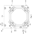
- Fig. 4 is a front view of the optical actuator 200 in Fig. 3 .
- Fig. 5 is another front view of the optical actuator 200 in Fig. 4 , in which the suspension bracket 240 is removed.
- the disposing areas 212b are respectively located at four corners of the base 210.
- the mounting surface 212a of the base 210 is substantially rectangular and has four corners. The four corners of the frame 230 are retracted relative to the mounting surface 212a, so that the mounting surface 212a has four disposing areas 212b relative to the frame 230, and the two lower disposing areas 212b are closer to the edge of the base 210.
- the contour of the outer edge of the frame 230 that is retracted relative to the mounting surface 212a is substantially octagonal, but the disclosure is not limited thereto. In practical applications, the contour of the outer edge of the frame 230 may be circular.
- the frame 230 of the optical actuator 200 includes a bottom frame 231 and a plurality of fixing plates 232.
- the light-transmitting plate 220 is supported on the bottom frame 231.
- the fixing plates 232 are fixed on the bottom frame 231 and respectively abut against different edges of the light-transmitting plate 220 to tightly fit and fix the light-transmitting plate 220.
- the number of fixing plates 232 is four.
- the contour of the outer edge of the light-transmitting plate 220 is substantially octagonal.
- the fixing plates 232 are located in two opposite corners of the light-transmitting plate 220.
- Fig. 6 is a front view of the suspension bracket 240 in Fig. 4 .
- the suspension bracket 240 further includes connection bar 242.
- the connection bar 242 is in a frame shape and connects the suspension members 241 in series. By connecting the suspension members 241 in series with the connection bar 242, the suspension bracket 240 can be made into a unitary structure, thereby increasing the convenience of installing the suspension bracket 240.
- Each of the suspension members 241 has a first fixing end 241a and a second fixing end 241b.
- the first fixing end 241a and the second fixing end 241b are structurally connected to each other and separated by a predetermined distance to maintain structural elasticity.
- the first fixing end 241a is located at an end of the suspension member 241 away from the connection bar 242.
- the second fixing end 241b is located at the junction between the suspension member 241 and the connection bar 242.
- the suspension member 241 is fixed to the base 210 through the first fixing end 241a (e.g., by screwing to the bottom plate 211 of the base 210).
- the suspension member 241 is fixed to the frame 230 through the second fixing end 241b (e.g., by screwing to the fixing plate 232 of the frame 230). In this way, the suspension bracket 240 can be connected between the base 210 and the frame 230.
- whether the suspension member 241 is located in the disposing area 212b can be determined based on whether the first fixing end 241a is located in the disposing area 212b. As shown in Figs. 4 and 6 , the first fixing ends 241a of the four suspension members 241 are respectively located in the four disposing areas 212b, so it can be determined that the suspension members 241 are respectively located in the four disposing areas 212b.
- each of the suspension members 241 includes two ribs. Two ends of each of the ribs are respectively connected to the first fixing end 241a and the second fixing end 241b, and the ribs protrude away from each other in opposite directions between the first fixing end 241a and the second fixing end 241b. Furthermore, the two ribs extend to two sides along the line connecting the first fixing end 241a and the second fixing end 241b and are symmetrical, so that the suspension member 241 forms a symmetrical butterfly wing structure. It should be noted that since the ribs are thinner than the connection bar 242, they are easier to elastically deform. In contrast, since the connection bar 242 is thicker than the ribs, the overall rigidity and stability of the suspension bracket 240 can be increased.
- connection bar 242 can be omitted from the suspension bracket 240. That is, the suspension bracket 240 may only include suspension members 241 that are separated from each other.
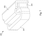
- Fig. 7 is a perspective view of the actuation member 250 in Fig. 2 .
- the actuation member 250 includes a coil 251, a magnetic conductive member 252, and a magnet 253.
- the coil 251 is fixed to the base 210 and electrically connected to the circuit board 212.
- the wire of the coil 251 is wound substantially parallel to the mounting surface 212a.
- the magnetic conductive member 252 is fixed to the frame 230 and partially penetrates into the surrounding space of the coil 251 (e.g., along the normal direction N shown in Fig. 3 ).
- the magnet 253 is fixed to the magnetic conductive member 252, and the magnetic force of the magnet 253 can be transmitted to the magnetic conductive member 252.
- the four fingers indicate the direction of positive charge movement, and the direction pointed by the thumb vertical to the four fingers is the direction of the Lorentz force. It can be seen from this that by flowing currents in different directions to the coil 251, the Lorentz force can be exerted on the magnetic conductive member 252 to reciprocate along the normal direction N. In this way, the actuation members 250 can drive the frame 230 to reciprocate along the normal direction N relative to the mounting surface 212a.
- two of the actuation members 250 are arranged along a first diagonal axis DA1.
- Other two of the actuation members 250 are arranged along a second diagonal axis DA2.
- the first diagonal axis DA1 and the second diagonal axis DA2 are perpendicular to each other.
- the image beam passing through the light-transmitting plate 220 can produce a pixel shift effect, and the image resolution can be improved after signal synchronization.
- the original resolution of 1920*1080 can be increased to 3840*2160, but the present disclosure is not limited thereto.
- the light valve module 130 has a length axis AL and a width axis AW.
- the length axis AL and the width axis AW are respectively parallel to the first diagonal axis DA1 and the second diagonal axis DA2.
- the optical actuator and the imaging device of the present disclosure by concentrating the suspension members and the actuation members on a plurality of disposing areas of the mounting surface of the base, the area of the mounting surface can be reduced, thereby effectively reducing the volume occupied by the optical actuator in the imaging device. In this way, the applicability of projection lenses with various focal lengths in the imaging device of the present disclosure can be effectively increased.
Landscapes
- Physics & Mathematics (AREA)
- General Physics & Mathematics (AREA)
- Optics & Photonics (AREA)
- Engineering & Computer Science (AREA)
- Multimedia (AREA)
- Signal Processing (AREA)
- Transforming Electric Information Into Light Information (AREA)
- Lens Barrels (AREA)
- Studio Devices (AREA)
- Mounting And Adjusting Of Optical Elements (AREA)
- Mechanical Light Control Or Optical Switches (AREA)
- Projection Apparatus (AREA)
Abstract
An optical actuator includes a base, a light-transmitting plate, a frame, a plurality of suspension members, and a plurality of actuation members. The base has a mounting surface. The light-transmitting plate is located above the mounting surface. The frame frames an outer edge of the light-transmitting plate. The frame retreats inwardly relative to the mounting surface, so that the mounting surface has a plurality of disposing areas relative to the frame. The suspension members are respectively located on the disposing areas and connected between the base and the frame. The actuation members are respectively located on the disposing area and configured to drive the frame to reciprocate relative to the mounting surface.
Description
- The present disclosure relates to an optical actuator and an imaging device.
- A projector is a display device used to produce large-size images. The imaging principle of the projector is to use the light valve module to convert the illumination beam generated by the light source module into an image beam, and then project the image beam onto the screen or wall through the projection lens.
- In order to improve the pixel quality of the projected images, some projectors have an optical actuator installed between the light valve module and the projection lens, and the vibration of the optical actuator causes the pixels to reciprocate appropriately to prevent the pixel particles in the projected images from being too obvious. Specifically, when the light generated by the light source module is modulated by the light valve module, the light is then transmitted to the projection lens through the optical actuator.
- However, existing optical actuators are large in size, so when used with projection lenses with partial focal lengths (for example, projection lenses with short back focus distances), the spaces between the prisms and the projection lenses are often limited and thus the problem of structural interference is encountered, which makes the optical actuators cannot be used.
- Accordingly, how to provide optical actuator and an imaging device that can solve the aforementioned problems becomes an important issue to be solved by those in the industry.
- An aspect of the disclosure is to provide an optical actuator and an imaging device.
- According to an embodiment of the disclosure, an optical actuator includes a base, a light-transmitting plate, a frame, a plurality of suspension members, and a plurality of actuation members. The base has a mounting surface. The light-transmitting plate is located above the mounting surface. The frame frames an outer edge of the light-transmitting plate. The frame retreats inwardly relative to the mounting surface, so that the mounting surface has a plurality of disposing areas relative to the frame. The suspension members are respectively located on the disposing areas and connected between the base and the frame. The actuation members are respectively located on the disposing areas and configured to drive the frame to reciprocate relative to the mounting surface.
- In one or more embodiments of the present disclosure, one of the suspension members and one of the actuation members on one of the disposing areas are arranged in a normal direction of the mounting surface.
- In one or more embodiments of the present disclosure, the actuation members are configured to drive the frame to reciprocate relative to the mounting surface along the normal direction.
- In one or more embodiments of the present disclosure, the disposing areas are respectively located at four corners of the base.
- In one or more embodiments of the present disclosure, two of the actuation members are arranged along a first diagonal axis. Other two of the actuation members are arranged along a second diagonal axis. The first diagonal axis and the second diagonal axis are perpendicular to each other.
- According to an embodiment of the disclosure, an imaging device includes a light valve module, an optical actuator, and a plurality of prisms. The optical actuator includes a base, a light-transmitting plate, a frame, a plurality of suspension members, and a plurality of actuation members. The base has a mounting surface. The light-transmitting plate is located above the mounting surface. The frame frames an outer edge of the light-transmitting plate. The frame retreats inwardly relative to the mounting surface, so that the mounting surface has a plurality of disposing areas relative to the frame. The suspension members are respectively located on the disposing areas and connected between the base and the frame. The actuation members are respectively located on the disposing area and configured to drive the frame to reciprocate relative to the mounting surface. The prisms are optically coupled between the light valve module and the light-transmitting plate.
- In one or more embodiments of the present disclosure, one of the suspension members and one of the actuation members on one of the disposing areas are arranged in a normal direction of the mounting surface.
- In one or more embodiments of the present disclosure, the actuation members are configured to drive the frame to reciprocate relative to the mounting surface along the normal direction.
- In one or more embodiments of the present disclosure, the disposing areas are respectively located at four corners of the base.
- In one or more embodiments of the present disclosure, two of the actuation members are arranged along a first diagonal axis. Other two of the actuation members are arranged along a second diagonal axis. The first diagonal axis and the second diagonal axis are perpendicular to each other.
- In one or more embodiments of the present disclosure, the first diagonal axis extends through two of the disposing areas. The second diagonal axis extends through other two of the disposing areas.
- In one or more embodiments of the present disclosure, the light valve module has a length axis and a width axis respectively parallel to the first diagonal axis and the second diagonal axis.
- In one or more embodiments of the present disclosure, the base further has a side surface connected to the mounting surface. The side surface is connected to two of the disposing areas. The prisms include a first prism and a second prism. The first prism is located between the light valve module and the light-transmitting plate. The second prism is partially located between the light valve module and the first prism and extends to a side of the side surface to form a gap with the side surface.
- In one or more embodiments of the present disclosure, one of the suspension members has a first fixing end and a second fixing end, and is fixed to the base and the frame respectively through the first fixing end and the second fixing end.
- In one or more embodiments of the present disclosure, the one of the suspension members includes two ribs. Two ends of each of the ribs are respectively connected to the first fixing end and the second fixing end. The ribs protrude away from each other in opposite directions between the first fixing end and the second fixing end.
- Accordingly, in the optical actuator and the imaging device of the present disclosure, by concentrating the suspension members and the actuation members on a plurality of disposing areas of the mounting surface of the base, the area of the mounting surface can be reduced, thereby effectively reducing the volume occupied by the optical actuator in the imaging device. In this way, the applicability of projection lenses with various focal lengths in the imaging device of the present disclosure can be effectively increased.
- It is to be understood that both the foregoing general description and the following detailed description are by examples, and are intended to provide further explanation of the disclosure as claimed.
- The disclosure can be more fully understood by reading the following detailed description of the embodiment, with reference made to the accompanying drawings as follows:
-
Fig. 1 is a schematic perspective view of an imaging device according to an embodiment of the present disclosure; -
Fig. 2 is a schematic perspective view of some components of the imaging device according to an embodiment of the present disclosure; -
Fig. 3 is a side view of the components inFig. 2 ; -
Fig. 4 is a front view of an optical actuator inFig. 3 ; -
Fig. 5 is another front view of the optical actuator inFig. 4 , in which a suspension bracket is removed; -
Fig. 6 is a front view of the suspension bracket inFig. 4 ; and -
Fig. 7 is a perspective view of an actuation member inFig. 2 . - Reference will now be made in detail to the present embodiments of the disclosure, examples of which are illustrated in the accompanying drawings. Wherever possible, the same reference numbers are used in the drawings and the description to refer to the same or like parts. However, specific structural and functional details disclosed herein are merely representative for purposes of describing example embodiments, and thus may be embodied in many alternate forms and should not be construed as limited to only example embodiments set forth herein. Therefore, it should be understood that there is no intent to limit example embodiments to the particular forms disclosed, but on the contrary, example embodiments are to cover all modifications, equivalents, and alternatives falling within the scope of the disclosure.
- Reference is made to
Figs. 1 and2 .Fig. 1 is a schematic perspective view of animaging device 100 according to an embodiment of the present disclosure.Fig. 2 is a schematic perspective view of some components of theimaging device 100 according to an embodiment of the present disclosure. As shown inFigs. 1 and2 , in the present embodiment, theimaging device 100 takes a projector as an example, but the present disclosure is not limited thereto. Theimaging device 100 includes ahousing 110 and a plurality of components disposed in thehousing 110. For example, theimaging device 100 includes aprojection lens 120, a light source module (not shown), alight valve module 130, anoptical actuator 200, and a plurality of prisms. The light source module is configured to generate an illumination beam. The prisms are optically coupled between the light source module and thelight valve module 130, and optically coupled between thelight valve module 130 and theoptical actuator 200. The illumination beam generated by the light source module first reaches thelight valve module 130 through the prisms. Thelight valve module 130 is configured to convert the illumination beam into an image beam. The image beam is projected onto the screen sequentially through the prisms, theoptical actuator 200, and theprojection lens 120. - In some embodiments, the
light valve module 130 is a digital micromirror device (DMD), but the present disclosure is not limited thereto. Specifically, when a certain pixel is to display an image, the corresponding micromirror element of thelight valve module 130 causes the image beam converted from the illumination beam to be projected outside thehousing 110 sequentially through the prisms, theoptical actuator 200, and theprojection lens 120. When a certain pixel is not expected to display an image, the corresponding micromirror element of thelight valve module 130 causes the image beam to deviate from theoptical actuator 200 after passing through the prisms, so that the image beam cannot be projected outside thehousing 110 through theprojection lens 120. - As shown in
Fig. 2 , in the present embodiment, theoptical actuator 200 includes abase 210, a light-transmittingplate 220, aframe 230, asuspension bracket 240, and a plurality ofactuation members 250. Thebase 210 has a mountingsurface 212a. The light-transmittingplate 220 is located above the mountingsurface 212a. Theframe 230 frames an outer edge of the light-transmittingplate 220. Theframe 230 retreats inwardly relative to the mountingsurface 212a, so that the mountingsurface 212a has a plurality of disposingareas 212b relative to theframe 230. Thesuspension bracket 240 includes a plurality ofsuspension members 241. Thesuspension members 241 are respectively located on the disposingareas 212b and connected between the base 210 and theframe 230. Theactuation members 250 are respectively located on the disposingareas 212b and configured to drive theframe 230 to reciprocate relative to the mountingsurface 212a. In detail, the function of thesuspension bracket 240 is to suspend theframe 230 at a predetermined distance above the mountingsurface 212a and maintain it parallel. Thesuspension bracket 240 also ensures that when theactuation members 250 drive theframe 230 to reciprocate, a certain moving space and the ability to elastically return are maintained. The prisms are optically coupled between thelight valve module 130 and the light-transmittingplate 220. - It can be clearly seen from the foregoing structural configurations that the
suspension members 241 and theactuation members 250 are respectively centrally disposed on the disposingareas 212b of the mountingsurface 212a of thebase 210. Therefore, the area of the mountingsurface 212a can be reduced, thereby effectively reducing the volume occupied by theoptical actuator 200 in theimaging device 100. - As shown in
Fig. 2 , in the present embodiment, thebase 210 includes abottom plate 211 and acircuit board 212. Thecircuit board 212 is disposed on the bottom plate 211 (e.g., by screws). Thebottom plate 211 is located on a side of the base 210 facing thelight valve module 130. Thecircuit board 212 is located on a side of the base 210 away from thelight valve module 130. The mountingsurface 212a is the surface of thecircuit board 212 away from thebottom plate 211. In some embodiments, the material of thebottom plate 211 includes metal, thereby improving the overall rigidity of thebase 210 and carrying thecircuit board 212. Thebottom plate 211 and thecircuit board 212 have hollow structures for allowing the image beam converted by thelight valve module 130 to pass through. - Reference is made to
Fig. 3. Fig. 3 is a side view of the components inFig. 2 . As shown inFigs. 2 and3 , in the present embodiment, the base 210 further has aside surface 212c connected to the mountingsurface 212a. Theside surface 212c is connected to two of the disposingareas 212b (e.g., the two disposingareas 212b located on the right and lower sides inFig. 2 and adjacent to the prisms). In other words, theside surface 212c is the surface of thecircuit board 212 facing the prisms. The prisms include afirst prism 141 and asecond prism 142. Thefirst prism 141 is located between thelight valve module 130 and the light-transmittingplate 220. Thesecond prism 142 is partially located between thelight valve module 130 and thefirst prism 141 and extends to a side of theside surface 212c to form a gap G with theside surface 212c. Since thesuspension members 241 and theactuation members 250 are centrally disposed on the disposingareas 212b of the mountingsurface 212a, an edge of theframe 230 of theoptical actuator 200 close to thesecond prism 142 can be closer to theside surface 212c of thebase 210. In this way, the distance between theoptical actuator 200 and thelight valve module 130 can be effectively reduced without structural interference between theoptical actuator 200 and thesecond prism 142, thereby effectively increasing the applicability of theprojection lenses 120 with various focal lengths in theimaging device 100 of the present disclosure. - As shown in
Fig. 3 , in the present embodiment, thebottom plate 211 of thebase 210 has aside surface 211a adjacent to thesecond prism 142, and theside surface 211a is inclined relative to theside surface 212c and is substantially parallel to the surface of thesecond prism 142 facing theoptical actuator 200. In this way, the distance between theoptical actuator 200 and thelight valve module 130 can be further reduced. - As shown in
Figs. 2 and3 , in the present embodiment, thesuspension member 241 and theactuation member 250 located on the same disposingarea 212b are arranged in a normal direction N of the mountingsurface 212a, which causes the action direction of theactuation member 250 and the elastically returning direction of thecorresponding suspension member 241 to move in the same normal direction N. It can be seen from this that each set of thesuspension members 241 andactuation members 250 actually move in the same disposingareas 212b on the mountingsurface 212a. Therefore, there are many positions around theframe 230 of theoptical actuator 200 that can be vacated for making room. - Reference is made to
Figs. 4 and5 .Fig. 4 is a front view of theoptical actuator 200 inFig. 3 .Fig. 5 is another front view of theoptical actuator 200 inFig. 4 , in which thesuspension bracket 240 is removed. As shown inFigs. 4 and5 , in the present embodiment, the disposingareas 212b are respectively located at four corners of thebase 210. Specifically, the mountingsurface 212a of thebase 210 is substantially rectangular and has four corners. The four corners of theframe 230 are retracted relative to the mountingsurface 212a, so that the mountingsurface 212a has four disposingareas 212b relative to theframe 230, and the two lower disposingareas 212b are closer to the edge of thebase 210. - As shown in
Fig. 5 , in the present embodiment, the contour of the outer edge of theframe 230 that is retracted relative to the mountingsurface 212a is substantially octagonal, but the disclosure is not limited thereto. In practical applications, the contour of the outer edge of theframe 230 may be circular. - As shown in
Fig. 5 , in the present embodiment, theframe 230 of theoptical actuator 200 includes abottom frame 231 and a plurality of fixingplates 232. The light-transmittingplate 220 is supported on thebottom frame 231. The fixingplates 232 are fixed on thebottom frame 231 and respectively abut against different edges of the light-transmittingplate 220 to tightly fit and fix the light-transmittingplate 220. In detail, as shown inFig. 5 , the number of fixingplates 232 is four. The contour of the outer edge of the light-transmittingplate 220 is substantially octagonal. The fixingplates 232 are located in two opposite corners of the light-transmittingplate 220. - Reference is made to
Fig. 6. Fig. 6 is a front view of thesuspension bracket 240 inFig. 4 . As shown inFigs. 4 and6 , in the present embodiment, thesuspension bracket 240 further includesconnection bar 242. Theconnection bar 242 is in a frame shape and connects thesuspension members 241 in series. By connecting thesuspension members 241 in series with theconnection bar 242, thesuspension bracket 240 can be made into a unitary structure, thereby increasing the convenience of installing thesuspension bracket 240. Each of thesuspension members 241 has afirst fixing end 241a and asecond fixing end 241b. Thefirst fixing end 241a and the second fixingend 241b are structurally connected to each other and separated by a predetermined distance to maintain structural elasticity. Thefirst fixing end 241a is located at an end of thesuspension member 241 away from theconnection bar 242. Thesecond fixing end 241b is located at the junction between thesuspension member 241 and theconnection bar 242. Thesuspension member 241 is fixed to the base 210 through the first fixingend 241a (e.g., by screwing to thebottom plate 211 of the base 210). Thesuspension member 241 is fixed to theframe 230 through the second fixingend 241b (e.g., by screwing to the fixingplate 232 of the frame 230). In this way, thesuspension bracket 240 can be connected between the base 210 and theframe 230. - In some embodiments, whether the
suspension member 241 is located in the disposingarea 212b can be determined based on whether the first fixingend 241a is located in the disposingarea 212b. As shown inFigs. 4 and6 , the first fixing ends 241a of the foursuspension members 241 are respectively located in the four disposingareas 212b, so it can be determined that thesuspension members 241 are respectively located in the four disposingareas 212b. - As shown in
Fig. 6 , in the present embodiment, each of thesuspension members 241 includes two ribs. Two ends of each of the ribs are respectively connected to the first fixingend 241a and the second fixingend 241b, and the ribs protrude away from each other in opposite directions between the first fixingend 241a and the second fixingend 241b. Furthermore, the two ribs extend to two sides along the line connecting the first fixingend 241a and the second fixingend 241b and are symmetrical, so that thesuspension member 241 forms a symmetrical butterfly wing structure. It should be noted that since the ribs are thinner than theconnection bar 242, they are easier to elastically deform. In contrast, since theconnection bar 242 is thicker than the ribs, the overall rigidity and stability of thesuspension bracket 240 can be increased. - In practical applications, the
connection bar 242 can be omitted from thesuspension bracket 240. That is, thesuspension bracket 240 may only includesuspension members 241 that are separated from each other. - Reference is made to
Fig. 7. Fig. 7 is a perspective view of theactuation member 250 inFig. 2 . As shown inFigs. 2 and7 , in the present embodiment, theactuation member 250 includes acoil 251, a magneticconductive member 252, and amagnet 253. Thecoil 251 is fixed to thebase 210 and electrically connected to thecircuit board 212. The wire of thecoil 251 is wound substantially parallel to the mountingsurface 212a. The magneticconductive member 252 is fixed to theframe 230 and partially penetrates into the surrounding space of the coil 251 (e.g., along the normal direction N shown inFig. 3 ). Themagnet 253 is fixed to the magneticconductive member 252, and the magnetic force of themagnet 253 can be transmitted to the magneticconductive member 252. According to the left-hand rule, when the left hand is placed in a magnetic field and the magnetic field lines penetrate vertically into the palm of the hand, the four fingers indicate the direction of positive charge movement, and the direction pointed by the thumb vertical to the four fingers is the direction of the Lorentz force. It can be seen from this that by flowing currents in different directions to thecoil 251, the Lorentz force can be exerted on the magneticconductive member 252 to reciprocate along the normal direction N. In this way, theactuation members 250 can drive theframe 230 to reciprocate along the normal direction N relative to the mountingsurface 212a. - As shown in
Fig. 2 , in the present embodiment, two of the actuation members 250 (i.e., theupper actuation member 250 and thelower actuation member 250 inFig. 2 ) are arranged along a first diagonal axis DA1. Other two of the actuation members 250 (i.e., theleft actuation member 250 and theright actuation member 250 inFig. 2 ) are arranged along a second diagonal axis DA2. The first diagonal axis DA1 and the second diagonal axis DA2 are perpendicular to each other. Furthermore, the disposingareas 212b, thesuspension members 241 with the first fixing ends 241a and the second fixing ends 241b thereof, and theactuation members 250 are arranged in the first diagonal axis DA1 or the second diagonal axis DA2. The first diagonal axis DA1 extends through the upper and lower disposingareas 212b inFig. 2 . The second diagonal axis DA2 extends through the left and right disposingareas 212b inFig. 2 . Theseactuation members 250 can actuate sequentially in time sequence. When theseactuation members 250 actuate sequentially, the optical axis of the light-transmittingplate 220 can be deflected toward different directions respectively. In this way, the image beam passing through the light-transmittingplate 220 can produce a pixel shift effect, and the image resolution can be improved after signal synchronization. For example, the original resolution of 1920*1080 can be increased to 3840*2160, but the present disclosure is not limited thereto. - As shown in
Fig. 2 , in the present embodiment, thelight valve module 130 has a length axis AL and a width axis AW. The length axis AL and the width axis AW are respectively parallel to the first diagonal axis DA1 and the second diagonal axis DA2. With the configurations, the image beam with thelight valve module 130 in the ON state can effectively pass through the light-transmittingplate 220, and the image beam can produce a predetermined pixel shift effect. - According to the foregoing recitations of the embodiments of the disclosure, it can be seen that in the optical actuator and the imaging device of the present disclosure, by concentrating the suspension members and the actuation members on a plurality of disposing areas of the mounting surface of the base, the area of the mounting surface can be reduced, thereby effectively reducing the volume occupied by the optical actuator in the imaging device. In this way, the applicability of projection lenses with various focal lengths in the imaging device of the present disclosure can be effectively increased.
- Although the present disclosure has been described in considerable detail with reference to certain embodiments thereof, other embodiments are possible. Therefore, the spirit and scope of the appended claims should not be limited to the description of the embodiments contained herein.
- It will be apparent to those skilled in the art that various modifications and variations can be made to the structure of the present disclosure without departing from the scope or spirit of the disclosure. In view of the foregoing, it is intended that the present disclosure cover modifications and variations of this disclosure provided they fall within the scope of the following claims.
Claims (15)
- An optical actuator (200), comprising:a base (210) having a mounting surface (212a);a light-transmitting plate (220) located above the mounting surface (212a);a frame (230) framing an outer edge of the light-transmitting plate (220), wherein the frame (230) retreats inwardly relative to the mounting surface (212a), so that the mounting surface (212a) has a plurality of disposing areas (212b) relative to the frame (230);a plurality of suspension members (241) respectively located on the disposing areas (212b) and connected between the base (210) and the frame (230); anda plurality of actuation members (250) respectively located on the disposing areas (212b) and configured to drive the frame (230) to reciprocate relative to the mounting surface (212a).
- The optical actuator (200) of claim 1, wherein one of the suspension members (241) and one of the actuation members (250) on one of the disposing areas (212b) are arranged in a normal direction (N) of the mounting surface (212a).
- The optical actuator (200) of claim 2, wherein the actuation members (250) are configured to drive the frame (230) to reciprocate relative to the mounting surface (212a) along the normal direction (N).
- The optical actuator (200) of claim 1, wherein the disposing areas (212b) are respectively located at four corners of the base (210).
- The optical actuator (200) of claim 1, wherein two of the actuation members (250) are arranged along a first diagonal axis (DA1), other two of the actuation members (250) are arranged along a second diagonal axis (DA2), and the first diagonal axis (DA1) and the second diagonal axis (DA2) are perpendicular to each other.
- An imaging device (100), comprising:a light valve module (130);an optical actuator (200) comprising:a base (210) having a mounting surface (212a);a light-transmitting plate (220) located above the mounting surface (212a);a frame (230) framing an outer edge of the light-transmitting plate (220), wherein the frame (230) retreats inwardly relative to the mounting surface (212a), so that the mounting surface (212a) has a plurality of disposing areas (212b) relative to the frame (230);a plurality of suspension members (241) respectively located on the disposing areas (212b) and connected between the base (210) and the frame (230); anda plurality of actuation members (250) respectively located on the disposing areas (212b) and configured to drive the frame (230) to reciprocate relative to the mounting surface (212a); anda plurality of prisms (141, 142) optically coupled between the light valve module (130) and the light-transmitting plate (220).
- The imaging device (100) of claim 6, wherein one of the suspension members (241) and one of the actuation members (250) on one of the disposing areas (212b) are arranged in a normal direction (N) of the mounting surface (212a).
- The imaging device (100) of claim 7, wherein the actuation members (250) are configured to drive the frame (230) to reciprocate relative to the mounting surface (212a) along the normal direction (N).
- The imaging device (100) of claim 6, wherein the disposing areas (212b) are respectively located at four corners of the base (210).
- The imaging device (100) of claim 6 wherein two of the actuation members (250) are arranged along a first diagonal axis (DA1), other two of the actuation members (250) are arranged along a second diagonal axis (DA2), and the first diagonal axis (DA1) and the second diagonal axis (DA2) are perpendicular to each other.
- The imaging device (100) of claim 10, wherein the first diagonal axis (DA1) extends through two of the disposing areas (212b), and the second diagonal axis (DA2) extends through other two of the disposing areas (212b).
- The imaging device (100) of claim 10, wherein the light valve module (130) has a length axis (AL) and a width axis (AW) respectively parallel to the first diagonal axis (DA1) and the second diagonal axis (DA2).
- The imaging device (100) of claim 12, wherein the base (210) further has a side surface (212c) connected to the mounting surface (212a), the side surface (212c) is connected to two of the disposing areas (212b), the prisms (141, 142) comprise a first prism (141) and a second prism (142), the first prism (141) is located between the light valve module (130) and the light-transmitting plate (220), and the second prism (142) is partially located between the light valve module (130) and the first prism (141) and extends to a side of the side surface (212c) to form a gap (G) with the side surface (212c).
- The imaging device (100) of claim 10, wherein one of the suspension members (241) has a first fixing end (241a) and a second fixing end (241b), and is fixed to the base (210) and the frame (230) respectively through the first fixing end (241a) and the second fixing end (241b).
- The imaging device (100) of claim 14, wherein the one of the suspension members (241) comprises two ribs, two ends of each of the ribs are respectively connected to the first fixing end (241a) and the second fixing end (241b), and the ribs protrude away from each other in opposite directions between the first fixing end (241a) and the second fixing end (241b).
Applications Claiming Priority (1)
| Application Number | Priority Date | Filing Date | Title |
|---|---|---|---|
| CN202311060967.4A CN119511615A (en) | 2023-08-22 | 2023-08-22 | Optical actuator and imaging device |
Publications (1)
| Publication Number | Publication Date |
|---|---|
| EP4513867A1 true EP4513867A1 (en) | 2025-02-26 |
Family
ID=90366076
Family Applications (1)
| Application Number | Title | Priority Date | Filing Date |
|---|---|---|---|
| EP24164050.7A Pending EP4513867A1 (en) | 2023-08-22 | 2024-03-18 | Optical actuator and imaging device |
Country Status (4)
| Country | Link |
|---|---|
| US (1) | US20250067939A1 (en) |
| EP (1) | EP4513867A1 (en) |
| JP (1) | JP2025031646A (en) |
| CN (1) | CN119511615A (en) |
Citations (4)
| Publication number | Priority date | Publication date | Assignee | Title |
|---|---|---|---|---|
| US7184218B1 (en) * | 2004-11-15 | 2007-02-27 | Arthur Berman | Method and apparatus for increasing quality and resolution of a projected image |
| US20100231780A1 (en) * | 2009-03-11 | 2010-09-16 | Olympus Imaging Corp. | Vibrating device and image equipment having the same |
| US20160004071A1 (en) * | 2014-07-01 | 2016-01-07 | Seiko Epson Corporation | Optical device and image display apparatus |
| US20170371173A1 (en) * | 2015-02-18 | 2017-12-28 | Imax Theatres International Limited | Despeckling System for Projected Light |
Family Cites Families (5)
| Publication number | Priority date | Publication date | Assignee | Title |
|---|---|---|---|---|
| JP2002014419A (en) * | 2000-06-28 | 2002-01-18 | Seiko Epson Corp | projector |
| US10892699B2 (en) * | 2017-10-12 | 2021-01-12 | Viewpoint Electronics Co., Ltd. | Inverse-movement-type voice coil actuating apparatus |
| US12353050B2 (en) * | 2018-08-07 | 2025-07-08 | Ningbo Sunny Opotech Co., Ltd | Camera apparatus, SMA driving device and manufacturing method, driving method and wiring method thereof |
| JP7563130B2 (en) * | 2020-11-20 | 2024-10-08 | セイコーエプソン株式会社 | Optical device and display device |
| JP2023049013A (en) * | 2021-09-28 | 2023-04-07 | 株式会社Jvcケンウッド | Optical path control device, display device and optical path control method |
-
2023
- 2023-08-22 CN CN202311060967.4A patent/CN119511615A/en active Pending
- 2023-12-22 US US18/393,760 patent/US20250067939A1/en active Pending
-
2024
- 2024-03-18 EP EP24164050.7A patent/EP4513867A1/en active Pending
- 2024-08-21 JP JP2024139751A patent/JP2025031646A/en active Pending
Patent Citations (4)
| Publication number | Priority date | Publication date | Assignee | Title |
|---|---|---|---|---|
| US7184218B1 (en) * | 2004-11-15 | 2007-02-27 | Arthur Berman | Method and apparatus for increasing quality and resolution of a projected image |
| US20100231780A1 (en) * | 2009-03-11 | 2010-09-16 | Olympus Imaging Corp. | Vibrating device and image equipment having the same |
| US20160004071A1 (en) * | 2014-07-01 | 2016-01-07 | Seiko Epson Corporation | Optical device and image display apparatus |
| US20170371173A1 (en) * | 2015-02-18 | 2017-12-28 | Imax Theatres International Limited | Despeckling System for Projected Light |
Also Published As
| Publication number | Publication date |
|---|---|
| CN119511615A (en) | 2025-02-25 |
| JP2025031646A (en) | 2025-03-07 |
| US20250067939A1 (en) | 2025-02-27 |
Similar Documents
| Publication | Publication Date | Title |
|---|---|---|
| US8529070B2 (en) | Projection optical apparatus | |
| TWI737875B (en) | Light path adjustment mechanism and fabrication method thereof | |
| CN211826870U (en) | Optical module and projection device | |
| TWI698696B (en) | Light path adjustment mechanism and fabrication method thereof | |
| US11422357B2 (en) | Optical system | |
| TWI691778B (en) | Light path adjustment mechanism and fabrication method thereof | |
| US11209723B2 (en) | Optical module and projector | |
| US20160004071A1 (en) | Optical device and image display apparatus | |
| US20250067939A1 (en) | Optical actuator and imaging device | |
| CN209267723U (en) | Optical devices and optical modules | |
| TWI854798B (en) | Optical actuator and imaging device | |
| CN111505891A (en) | A micro-module and opto-mechanical for deflecting optical filters | |
| JP3757222B2 (en) | Projection display | |
| CN111766673A (en) | Optical path adjustment mechanism and manufacturing method thereof | |
| CN110542976B (en) | Optical path adjustment mechanism and manufacturing method thereof | |
| CN111766674B (en) | Optical path adjustment mechanism and manufacturing method thereof | |
| TWI765235B (en) | Light path adjustment mechanism and fabrication method thereof | |
| CN113835183B (en) | Optical path adjustment mechanism and manufacturing method thereof | |
| WO2023188533A1 (en) | Optical path changing device and projection-type image display device provided with same | |
| CN100397239C (en) | Projection lens assembly and vibration device thereof | |
| KR100743291B1 (en) | Light Tunnel Fixation Structure of DLP Projection Television | |
| CN214409563U (en) | Projection device | |
| JP2679103B2 (en) | Projection lens system | |
| KR100693530B1 (en) | Light Tunnel Structure of DLP Projection Television | |
| KR100739559B1 (en) | projection television |
Legal Events
| Date | Code | Title | Description |
|---|---|---|---|
| PUAI | Public reference made under article 153(3) epc to a published international application that has entered the european phase |
Free format text: ORIGINAL CODE: 0009012 |
|
| STAA | Information on the status of an ep patent application or granted ep patent |
Free format text: STATUS: THE APPLICATION HAS BEEN PUBLISHED |
|
| AK | Designated contracting states |
Kind code of ref document: A1 Designated state(s): AL AT BE BG CH CY CZ DE DK EE ES FI FR GB GR HR HU IE IS IT LI LT LU LV MC ME MK MT NL NO PL PT RO RS SE SI SK SM TR |
|
| STAA | Information on the status of an ep patent application or granted ep patent |
Free format text: STATUS: REQUEST FOR EXAMINATION WAS MADE |
|
| 17P | Request for examination filed |
Effective date: 20250227 |