EP4513810A1 - Information transmission method and apparatus, and terminal device and network device - Google Patents

Information transmission method and apparatus, and terminal device and network device Download PDF

Info

Publication number
EP4513810A1
EP4513810A1 EP23791320.7A EP23791320A EP4513810A1 EP 4513810 A1 EP4513810 A1 EP 4513810A1 EP 23791320 A EP23791320 A EP 23791320A EP 4513810 A1 EP4513810 A1 EP 4513810A1
Authority
EP
European Patent Office
Prior art keywords
srs
max
mod
index
antenna ports
Prior art date
Legal status (The legal status is an assumption and is not a legal conclusion. Google has not performed a legal analysis and makes no representation as to the accuracy of the status listed.)
Pending
Application number
EP23791320.7A
Other languages
German (de)
French (fr)
Other versions
EP4513810A4 (en
Inventor
Qiuping Huang
Qiubin Gao
Current Assignee (The listed assignees may be inaccurate. Google has not performed a legal analysis and makes no representation or warranty as to the accuracy of the list.)
Datang Mobile Communications Equipment Co Ltd
Original Assignee
Datang Mobile Communications Equipment Co Ltd
Priority date (The priority date is an assumption and is not a legal conclusion. Google has not performed a legal analysis and makes no representation as to the accuracy of the date listed.)
Filing date
Publication date
Application filed by Datang Mobile Communications Equipment Co Ltd filed Critical Datang Mobile Communications Equipment Co Ltd
Publication of EP4513810A1 publication Critical patent/EP4513810A1/en
Publication of EP4513810A4 publication Critical patent/EP4513810A4/en
Pending legal-status Critical Current

Links

Images

Classifications

    • HELECTRICITY
    • H04ELECTRIC COMMUNICATION TECHNIQUE
    • H04LTRANSMISSION OF DIGITAL INFORMATION, e.g. TELEGRAPHIC COMMUNICATION
    • H04L5/00Arrangements affording multiple use of the transmission path
    • H04L5/003Arrangements for allocating sub-channels of the transmission path
    • H04L5/0048Allocation of pilot signals, i.e. of signals known to the receiver
    • H04L5/0051Allocation of pilot signals, i.e. of signals known to the receiver of dedicated pilots, i.e. pilots destined for a single user or terminal
    • HELECTRICITY
    • H04ELECTRIC COMMUNICATION TECHNIQUE
    • H04LTRANSMISSION OF DIGITAL INFORMATION, e.g. TELEGRAPHIC COMMUNICATION
    • H04L25/00Baseband systems
    • H04L25/02Details ; arrangements for supplying electrical power along data transmission lines
    • H04L25/0202Channel estimation
    • H04L25/0224Channel estimation using sounding signals
    • H04L25/0226Channel estimation using sounding signals sounding signals per se
    • HELECTRICITY
    • H04ELECTRIC COMMUNICATION TECHNIQUE
    • H04LTRANSMISSION OF DIGITAL INFORMATION, e.g. TELEGRAPHIC COMMUNICATION
    • H04L27/00Modulated-carrier systems
    • H04L27/26Systems using multi-frequency codes
    • H04L27/2601Multicarrier modulation systems
    • H04L27/2602Signal structure
    • H04L27/2605Symbol extensions, e.g. Zero Tail, Unique Word [UW]
    • HELECTRICITY
    • H04ELECTRIC COMMUNICATION TECHNIQUE
    • H04LTRANSMISSION OF DIGITAL INFORMATION, e.g. TELEGRAPHIC COMMUNICATION
    • H04L5/00Arrangements affording multiple use of the transmission path
    • H04L5/0001Arrangements for dividing the transmission path
    • H04L5/0003Two-dimensional division
    • H04L5/0005Time-frequency
    • H04L5/0007Time-frequency the frequencies being orthogonal, e.g. OFDM(A) or DMT
    • HELECTRICITY
    • H04ELECTRIC COMMUNICATION TECHNIQUE
    • H04LTRANSMISSION OF DIGITAL INFORMATION, e.g. TELEGRAPHIC COMMUNICATION
    • H04L5/00Arrangements affording multiple use of the transmission path
    • H04L5/0091Signalling for the administration of the divided path, e.g. signalling of configuration information
    • H04L5/0094Indication of how sub-channels of the path are allocated
    • HELECTRICITY
    • H04ELECTRIC COMMUNICATION TECHNIQUE
    • H04WWIRELESS COMMUNICATION NETWORKS
    • H04W72/00Local resource management
    • H04W72/04Wireless resource allocation
    • H04W72/044Wireless resource allocation based on the type of the allocated resource
    • H04W72/0446Resources in time domain, e.g. slots or frames
    • HELECTRICITY
    • H04ELECTRIC COMMUNICATION TECHNIQUE
    • H04WWIRELESS COMMUNICATION NETWORKS
    • H04W72/00Local resource management
    • H04W72/04Wireless resource allocation
    • H04W72/044Wireless resource allocation based on the type of the allocated resource
    • H04W72/0453Resources in frequency domain, e.g. a carrier in FDMA
    • HELECTRICITY
    • H04ELECTRIC COMMUNICATION TECHNIQUE
    • H04BTRANSMISSION
    • H04B7/00Radio transmission systems, i.e. using radiation field
    • H04B7/02Diversity systems; Multi-antenna system, i.e. transmission or reception using multiple antennas
    • H04B7/04Diversity systems; Multi-antenna system, i.e. transmission or reception using multiple antennas using two or more spaced independent antennas
    • H04B7/06Diversity systems; Multi-antenna system, i.e. transmission or reception using multiple antennas using two or more spaced independent antennas at the transmitting station
    • H04B7/0602Diversity systems; Multi-antenna system, i.e. transmission or reception using multiple antennas using two or more spaced independent antennas at the transmitting station using antenna switching
    • H04B7/0608Antenna selection according to transmission parameters

Definitions

  • the Sounding Reference Signal may be used for the acquisition of uplink Channel State Information (CSI), the acquisition of downlink CSI, the beam management, etc. Since the uplink transmission supports at most four transmitting antennas, the system of the related art only supports SRS resources of 1, 2 or 4 antenna ports. With the increase of terminal types, some terminals can support up to 8 transmitting antennas.
  • At least two antenna ports in the eight ports of the 8-port SRS resource use the same cyclic shift on the same time-frequency resource and then interfere with each other, which affects the performance.
  • the embodiments of the present disclosure provide an information transmission method and apparatus, a terminal device, and a network device to solve the problem in the related art that due to the sequence generation and resource mapping mode of the SRS resources, the number of SRS ports accommodated in the same SRS resource on the same time domain resource is limited, such that at least two antenna ports in a plurality of ports of an SRS resource with multiple ports use the same cyclic shift on the same time-frequency resource and then interfere with each other, which affects the performance.
  • an information transmission method including:
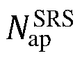
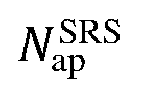
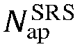
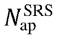
  • the N ap SRS antenna ports include a plurality of antenna port groups each corresponding to one group of time domain resources and/or frequency domain resources.
  • the method before the transmitting an SRS corresponding to the SRS resource, the method further includes:
  • the grouping of the N ap SRS antenna ports satisfies at least one of the following:
  • the cyclic shift offset values corresponding to the SRS sequences which are corresponding to the antenna ports included in different antenna port groups among the plurality of antenna port groups are the same.
  • the grouping of the N ap SRS antenna ports satisfies one of the following:
  • the configuration information includes information indicative of the first information.
  • the sequence generation parameter of the SRS includes at least one of a maximum number of cyclic shifts and a cyclic shift configuration.
  • the resource mapping mode information includes one of the following:
  • the grouping information of the N ap SRS antenna ports includes the number of the groups, which includes at least one of:
  • the method before the transmitting an SRS corresponding to the SRS resource, the method further includes:
  • the antenna ports in different antenna port groups adopt different formulas to determine the cyclic shift offset value.
  • the transmitting an SRS corresponding to the SRS resource includes:
  • the transmitting an SRS corresponding to the SRS resource includes:
  • the transmitting an SRS corresponding to the SRS resource includes:
  • the antenna ports in different antenna port groups adopt different formulas to determine the cyclic shift offset value.
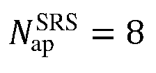
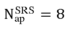
  • the N ap SRS is valued as 8.
  • An embodiment of the present disclosure further provides an information transmission method, including:
  • the N ap SRS antenna ports include a plurality of antenna port groups each corresponding to one group of time domain resources and/or frequency domain resources.
  • the method before the receiving an SRS corresponding to the configuration information and a transmission rule, the method further includes:
  • the grouping of the N ap SRS antenna ports satisfies at least one of the following:
  • the cyclic shift offset values corresponding to the SRS sequences which are corresponding to the antenna ports included in different antenna port groups among the plurality of antenna port groups are the same.
  • the configuration information includes information indicative of and determined based on the first information.
  • the sequence generation parameter of the SRS includes at least one of a maximum number of cyclic shifts and a cyclic shift configuration.
  • the grouping information of the N ap SRS antenna ports includes the number of the groups, which includes at least one of:
  • the method further includes at least one of the following:
  • the method before the receiving an SRS corresponding to the configuration information and a transmission rule, the method further includes:
  • the method before the receiving an SRS corresponding to the configuration information and a transmission rule, the method further includes:
  • the method before the receiving an SRS corresponding to the configuration information and a transmission rule, the method further includes:
  • the method before the receiving an SRS corresponding to the configuration information and a transmission rule, the method further includes:
  • the antenna ports in different antenna port groups adopt different formulas to determine the cyclic shift offset value.
  • the receiving an SRS corresponding to the configuration information and a transmission rule includes:
  • the receiving an SRS corresponding to the configuration information and a transmission rule includes:
  • the receiving an SRS corresponding to the configuration information and a transmission rule includes:
  • the antenna ports in different antenna port groups adopt different formulas to determine the cyclic shift offset value.
  • the N ap SRS is valued as 8.
  • An embodiment of the present disclosure further provides a terminal device, including a memory, a transceiver and a processor: the memory is configured to store a computer program; the transceiver is configured to transceive data under the control of the processor; and the processor is configured to read the computer program in the memory and perform processes of:
  • the N ap SRS antenna ports include a plurality of antenna port groups each corresponding to one group of time domain resources and/or frequency domain resources.
  • the processor reads the computer program in the memory and performs one of operations of:
  • the grouping of the N ap SRS antenna ports satisfies at least one of the following:
  • the cyclic shift offset values corresponding to the SRS sequences which are corresponding to the antenna ports included in different antenna port groups among the plurality of antenna port groups are the same.
  • the grouping of the N ap SRS antenna ports satisfies one of the following:
  • the configuration information includes information indicative of the first information.
  • the sequence generation parameter of the SRS includes at least one of a maximum number of cyclic shifts and a cyclic shift configuration.
  • the resource mapping mode information includes one of the following:
  • the grouping information of the N ap SRS antenna ports includes the number of the groups, which includes at least one of:
  • the processor reads the computer program in the memory and performs an operation of:
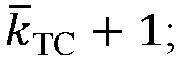
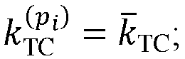
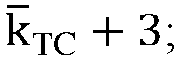
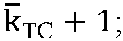
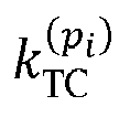
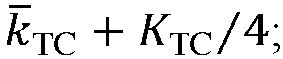
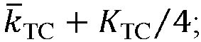
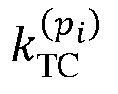
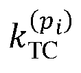
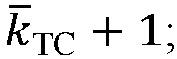
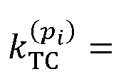
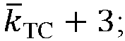
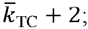
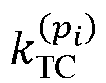
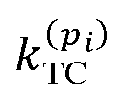
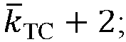
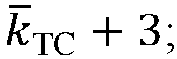
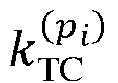
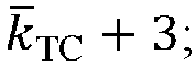
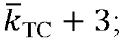
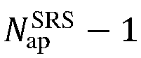
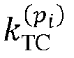
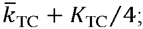
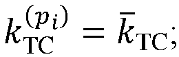
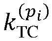
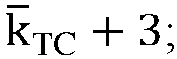
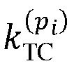
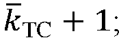
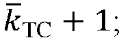
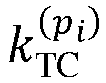
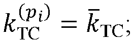
  • the processor reads the computer program in the memory and performs operations of: determining a position parameter k TC p i of a frequency domain resource corresponding to an antenna port with an index of i among the N ap SRS antenna ports based on at least one of: k ⁇ TC + 3 ; k ⁇ TC + 2 ; k ⁇ TC + 1 ; k ⁇ TC + 3 K TC / 4 ; k ⁇ TC + K TC / 4 ; k ⁇ TC + 4 ;
  • the antenna ports in different antenna port groups adopt different formulas to determine the cyclic shift offset value.
  • the N ap SRS is valued as 8.
  • An embodiment of the present disclosure further provides a network device, including a memory, a transceiver and a processor: the memory is configured to store a computer program; the transceiver is configured to transceive data under the control of the processor; and the processor is configured to read the computer program in the memory and perform processes of:
  • the N ap SRS antenna ports include a plurality of antenna port groups each corresponding to one group of time domain resources and/or frequency domain resources.
  • the processor reads the computer program in the memory and performs processes of:
  • the grouping of the N ap SRS antenna ports satisfies at least one of the following:
  • the cyclic shift offset values corresponding to the SRS sequences which are corresponding to the antenna ports included in different antenna port groups among the plurality of antenna port groups are the same.
  • the grouping of the N ap SRS antenna ports satisfies one of the following:
  • the configuration information includes information indicative of and determined based on the first information.
  • the sequence generation parameter of the SRS includes at least one of a maximum number of cyclic shifts and a cyclic shift configuration.
  • the resource mapping mode information includes one of the following:
  • the grouping information of the N ap SRS antenna ports includes the number of the groups, which includes at least one of:
  • the processor reads the computer program in the memory and performs one of processes of:
  • the processor reads the computer program in the memory and performs one of processes of:
  • the processor reads the computer program in the memory and performs one of processes of:
  • the processor reads the computer program in the memory and performs one of processes of:
  • the processor reads the computer program in the memory and performs one of processes of:
  • the antenna ports in different antenna port groups adopt different formulas to determine the cyclic shift offset value.
  • the processor reads the computer program in the memory and performs a process of:
  • the processor reads the computer program in the memory and performs a process of:
  • the antenna ports in different antenna port groups adopt different formulas to determine the cyclic shift offset value.
  • the N ap SRS is valued as 8.
  • An embodiment of the present disclosure further provides an information transmission apparatus, including:
  • the N ap SRS antenna ports include a plurality of antenna port groups each corresponding to one group of time domain resources and/or frequency domain resources.
  • the apparatus before the transmission unit transmits the SRS corresponding to the SRS resource, the apparatus further includes:
  • the grouping of the N ap SRS antenna ports satisfies at least one of the following:
  • the grouping of the N ap SRS antenna ports satisfies at least one of the following:
  • the configuration information includes information indicative of the first information.
  • the sequence generation parameter of the SRS includes at least one of a maximum number of cyclic shifts and a cyclic shift configuration.
  • the resource mapping mode information includes one of the following:
  • the apparatus further includes: a first determination unit configured to, according to the first information, determine at least one of a grouping of the N ap SRS antenna ports, the SRS sequence corresponding to each of the N ap SRS antenna ports, and the time domain resource and/or the frequency domain resource to which each of the N ap SRS antenna ports is mapped.
  • a first determination unit configured to, according to the first information, determine at least one of a grouping of the N ap SRS antenna ports, the SRS sequence corresponding to each of the N ap SRS antenna ports, and the time domain resource and/or the frequency domain resource to which each of the N ap SRS antenna ports is mapped.
  • the grouping information of the N ap SRS antenna ports includes the number of the groups, which includes at least one of:
  • the apparatus further includes:
  • the apparatus before the transmission unit transmits the SRS corresponding to the SRS resource, the apparatus further includes:
  • the apparatus before the transmission unit transmits the SRS corresponding to the SRS resource, the apparatus further includes:
  • the apparatus before the transmission unit transmits the SRS corresponding to the SRS resource, the apparatus further includes:
  • the apparatus before the transmission unit transmits the SRS corresponding to the SRS resource, the apparatus further includes:
  • the antenna ports in different antenna port groups adopt different formulas to determine the cyclic shift offset value.
  • the transmission unit is configured to:
  • the transmission unit is configured to:
  • the transmission unit is configured to:
  • the antenna ports in different antenna port groups adopt different formulas to determine the cyclic shift offset value.
  • the N ap SRS is valued as 8.
  • An embodiment of the present disclosure further provides an information transmission apparatus, including:
  • the N ap SRS antenna ports include a plurality of antenna port groups each corresponding to one group of time domain resources and/or frequency domain resources.
  • the apparatus before the second reception unit receives the SRS corresponding to the configuration information and the transmission rule, the apparatus further includes:
  • the grouping of the N ap SRS antenna ports satisfies at least one of the following:
  • the cyclic shift offset values corresponding to the SRS sequences which are corresponding to the antenna ports included in different antenna port groups among the plurality of antenna port groups are the same.
  • the grouping of the N ap SRS antenna ports satisfies one of the following:
  • the configuration information includes information indicative of and determined based on the first information.
  • the sequence generation parameter of the SRS includes at least one of a maximum number of cyclic shifts and a cyclic shift configuration.
  • the resource mapping mode information includes one of the following:
  • the grouping information of the N ap SRS antenna ports includes the number of the groups, which includes at least one of:
  • the apparatus further includes at least one of:
  • the apparatus before the reception unit receives the SRS corresponding to the configuration information and the transmission rule, the apparatus further includes:
  • the apparatus before the reception unit receives the SRS corresponding to the configuration information and the transmission rule, the apparatus further includes:
  • the apparatus before the reception unit receives the SRS corresponding to the configuration information and the transmission rule, the apparatus further includes:
  • the apparatus before the reception unit receives the SRS corresponding to the configuration information and the transmission rule, the apparatus further includes:
  • the antenna ports in different antenna port groups adopt different formulas to determine the cyclic shift offset value.
  • the reception unit is configured to:
  • the reception unit is configured to:
  • the reception unit is configured to:
  • the antenna ports in different antenna port groups adopt different formulas to determine the cyclic shift offset value.
  • the N ap SRS is valued as 8.
  • An embodiment of the present disclosure further provides a processor-readable storage medium which stores a computer program for causing a processor to perform the above method.
  • the SRS transmission is carried out based on a preset transmission rule, so as to avoid the problem that at least two antenna ports in a plurality of ports of a multi-port SRS resource use the same cyclic shift on the same time-frequency resource and then interfere with each other.
  • the embodiments of the present disclosure can ensure that the performance of the terminal will not be affected.
  • the word such as “exemplary” or “for example” is used to indicate an example, an illustration, or an explanation. Any embodiment or design solution described with “exemplary” or “for example” in the embodiments of the present disclosure should not be construed as more preferable or more advantageous than any other embodiment or design solution. To be exact, the use of the word such as “exemplary” or “for example” is intended to present related concepts in a specific manner.
  • An information transmission method and apparatus, a terminal device, and a network device provided in the embodiments of the present disclosure can be applied to a wireless communication system.
  • the embodiments of the present disclosure are applicable to various communication systems, including but not limited to a 5 th Generation (5G) mobile communication technology system (e.g., an NR system), a 6G system or an evolution system thereof, other systems based on Orthogonal Frequency Division Multiplexing (OFDM), other systems based on Discrete Fourier Transform Spread OFDM (DFT-S-OFDM), etc.
  • 5G 5 th Generation
  • NR Universal Terrestriality
  • 6G system 6G system
  • OFDM Orthogonal Frequency Division Multiplexing
  • DFT-S-OFDM Discrete Fourier Transform Spread OFDM
  • the applicable system may be a Global System Of Mobile communication (GSM) system, a Code Division Multiple Access (CDMA) system, a Wideband Code Division Multiple Access (WCDMA) general packet radio service (GPRS) system, a Long Term Evolution (LTE) system, an LTE Frequency Division Duplex (FDD) system, an LTE Time Division Duplex (TDD) system, a Long Term Evolution Advanced (LTE-A) system, a Universal Mobile Telecommunication System (UMTS), a Worldwide Interoperability For Microwave Access (WiMAX) system, a 5G New Radio (NR) system, etc.
  • GSM Global System Of Mobile communication
  • CDMA Code Division Multiple Access
  • WCDMA Wideband Code Division Multiple Access
  • GPRS general packet radio service
  • LTE Long Term Evolution
  • FDD Frequency Division Duplex
  • TDD Time Division Duplex
  • LTE-A Long Term Evolution Advanced
  • UMTS Universal Mobile Telecommunication System
  • WiMAX Worldwide Interoperability For Microwave Access
  • NR 5
  • the network system includes a user terminal 11 and a network device 12, where the user terminal 11 may be a User Equipment (UE), such as a cellular phone, a tablet personal computer, a laptop computer, a Personal Digital Assistant (PDA), a Mobile Internet Device (MID), a wearable device, or any other terminal side device.
  • UE User Equipment
  • PDA Personal Digital Assistant
  • MID Mobile Internet Device
  • wearable device any other terminal side device.
  • UE User Equipment
  • the specific type of the user terminal 11 is not limited in the embodiments of the present disclosure.
  • the network device 12 may be a base station of 5G or a higher version (e.g., gNB or 5G NR NB), or a base station in other communication systems, or referred to as nodeB, a Radio Network Controller (RNC), a Base Station Controller (BSC), a Base Transceiver Station (BTS), a home base station (e.g., a home evolved nodeB, or a home nodeB (HNB)), a BaseBand Unit (BBU), a Transmitting And Receiving Point (TRP), a Transmitting Point (TP), a mobile switching center, etc.
  • RNC Radio Network Controller
  • BSC Base Station Controller
  • BTS Base Transceiver Station
  • HNB home nodeB
  • BBU BaseBand Unit
  • TRP Transmitting And Receiving Point
  • TP Transmitting Point
  • FIG. 1 is merely an example and is not intended to limit the type of the communication system and the number, type, etc. of devices included in the communication system.
  • the network architectures and the service scenarios described in the embodiments of the present disclosure are for the purpose of illustrating, rather than limiting, the technical solutions in the embodiments of the present disclosure. Those of ordinary skill in the art will appreciate that with the evolution of the network architectures and the emergence of new service scenarios, the technical solutions in the embodiments of the present disclosure are also applicable to similar technical problems.
  • the embodiments of the present disclosure provide an information transmission method and apparatus, a terminal device, and a network device, so as to solve the problem in the related art that due to the sequence generation and resource mapping mode of the SRS resources, at least two antenna ports in a plurality of ports of an SRS resource with multiple ports use the same cyclic shift on the same time-frequency resource and then interfere with each other, which affects the performance.
  • the method and the apparatus are concepted based on the same application. Since the method and the apparatus adopt similar principles to solve the above problem, the implementations of the apparatus and the method can refer to each other, and the repeated contents will be omitted.
  • an embodiment of the present disclosure provides an information transmission method performed by a terminal device, including: Step S201: receiving configuration information of a Sounding Reference Signal (SRS) resource;
  • SRS Sounding Reference Signal
  • the configuration information of the SRS resource includes an identifier of the SRS resource, the number of SRS ports, a starting symbol, the number of occupied time domain symbols, or the like.
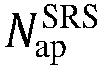
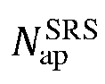
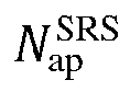
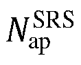
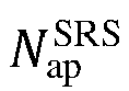
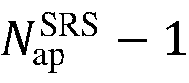
  • Step S202 transmitting an SRS corresponding to the SRS resource according to the configuration information and a transmission rule; where the SRS resource includes N ap SRS antenna ports, and the transmission rule includes at least one of the following:
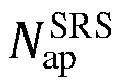
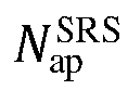
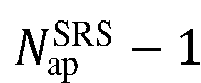
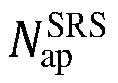
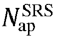
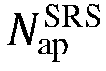
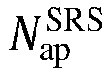
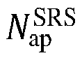
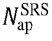
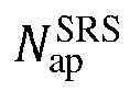
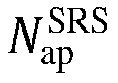
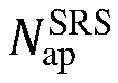
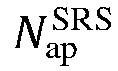
  • the SRS resource includes N ap SRS antenna ports may be understood as that the SRS resource is configured with N ap SRS SRS ports; or the SRS resource is corresponding to N ap SRS SRS ports; or N ap SRS SRS ports of the SRS resource.
  • the cyclic shift offset values are used to determine the SRS sequences.
  • the cyclic shift offset values corresponding to the SRS sequences which are corresponding to part of the antenna ports in the N ap SRS antenna ports are set to be continuous.
  • the N ap SRS antenna ports are grouped into a plurality of groups, where the cyclic shift offset values corresponding to the SRS sequences which are corresponding to the antenna ports in at least one of the plurality of groups are set to be continuous.
  • the above numerical values are only examples for illustrating continuity and discontinuity, and do not mean that the above numerical values are used during practical applications.
  • the SRS ports are grouped in the embodiment of the present disclosure.
  • the N ap SRS SRS ports include N antenna port groups, where N is an integer greater than or equal to 1.
  • each of the plurality of antenna port groups is corresponding to one group of time domain resources and/or frequency domain resources, i.e., the antenna port groups are in one-to-one correspondence with the time domain resource groups and/or the frequency domain resource groups.
  • the N ap SRS antenna ports are mapped to at least two groups of time domain resources; optionally, the N ap SRS antenna ports are mapped to at least two groups of frequency domain resources; and optionally, the N ap SRS antenna ports are mapped to at least two groups of time domain resources and frequency domain resources.
  • the N ap SRS antenna ports of one SRS resource include a plurality of groups, the cyclic shift values corresponding to any two antenna ports in each group are different, and the cyclic shift values corresponding to the antenna ports of any two groups are the same.
  • N ap SRS 8 antenna ports of one SRS resource
  • antenna ports 0, 2, 4 and 6 are in one group
  • antenna ports 1, 3, 5 and 7 are in another group
  • the SRS sequences of the antenna ports 0, 2, 4 and 6 are corresponding to the cyclic shift values 0, 2, 4 and 6, respectively
  • the SRS sequences of antenna ports 1, 3, 5 and 7 are corresponding to the cyclic shift values 0, 2, 4 and 6, respectively.
  • the transmission rule may be determined based on the first information, and the SRS corresponding to the SRS resource may be transmitted based on the configuration information and the transmission rule.
  • the grouping information of the antenna ports is grouping information of the N ap SRS antenna ports.
  • the grouping information of the antenna ports includes the number of the groups, which includes at least one of:
  • the time domain resources corresponding to one group of SRS ports may also be referred to as a group of time domain resources.
  • B113 the number of the frequency domain resource groups to which the SRS sequences are mapped;
  • the frequency domain resources corresponding to one group of SRS ports may also be referred to as a group of frequency domain resources.
  • a possible corresponding relationship includes:
  • the grouping information of the antenna ports may be indicated to the terminal by the network device through at least one of Radio Resource Control (RRC) signaling, Medium Access Control-Control Element (MAC-CE) signaling, or Downlink Control Information (DCI) signaling, and may also be determined by the terminal based on a corresponding relationship between the grouping information and one or more of the number of the antenna ports, the sequence generation parameter, or the number of the groups.
  • RRC Radio Resource Control
  • MAC-CE Medium Access Control-Control Element
  • DCI Downlink Control Information
  • the antenna ports with adjacent serial numbers are in one group.
  • indexes of the antenna ports included in each of the antenna port groups are at an interval of a preset value
  • the antenna are grouped based on the serial numbers at an interval. For example, the antenna ports with the serial numbers at an interval of 1 are grouped into one group. For another example, the antenna ports with the serial numbers at an interval of 3 are grouped into one group.
  • the grouping of the N ap SRS antenna ports satisfies one of the following: B116: the N ap SRS antenna ports are in one group;
  • all of the antenna ports are in one group. That is, the N ap SRS antenna ports are in one group.
  • the N ap SRS antenna ports are corresponding to a same resource.
  • each group has a same number of the antenna ports.
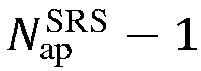
  • N ap SRS > 4 .
  • N ap SRS 8 .
  • N ap SRS 4
  • some possible grouping modes include (the following numerals represent the serial numbers of the SRS ports, and the serial numbers of all of the SRS ports in one SRS port group are included in one pair of brackets):
  • the possible grouping modes include (the following numerals represent the serial numbers of the SRS ports, and the serial numbers of all of the SRS ports in one SRS port group are included in one pair of brackets): ⁇ 1000 ⁇ and ⁇ 1001 ⁇ ; that is, there are 2 groups in total and each of the antenna ports is one group.
  • the terminal may determine the time domain resources and/or the frequency domain resources (which may also be understood as a resource mapping mode) corresponding to the SRS ports of the SRS resource based on the corresponding relationship.
  • the sequence generation parameter of the SRS and the number of time domain resource groups and/or the number of frequency domain resource groups of the SRS ports, and the terminal may determine the number of time domain resource groups and/or the number of frequency domain resource groups corresponding to the SRS ports of the SRS resource based on the sequence generation parameter of the SRS and the corresponding relationship.
  • the terminal and the network device pre-appoint (e.g., by a protocol) the corresponding relationship between the number of time domain resource groups and/or the number of frequency domain resource groups and the time domain resources and/or the frequency domain resources, the terminal may further determine the time domain resources and the frequency domain resources corresponding to the SRS ports, excluding the SRS resource.
  • the sequence generation parameter of the SRS includes at least one of a maximum number of cyclic shifts and a cyclic shift configuration.
  • the maximum number of cyclic shifts may be obtained as follows: the maximum number of cyclic shifts corresponding to the SRS sequence is determined according to a corresponding relationship between a first parameter and the maximum number of cyclic shifts, where the first parameter is used to determine a transmission comb number corresponding to the SRS resource, and is represented by a symbol K TC .
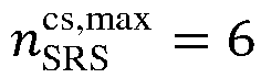
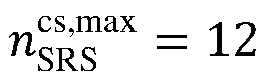
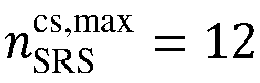
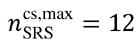
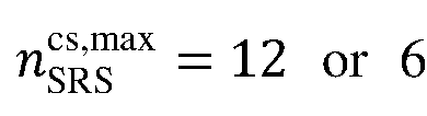
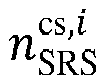
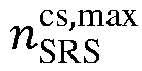
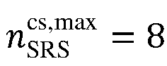
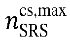
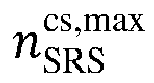
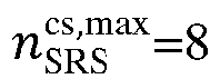
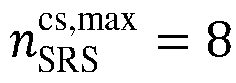
  • mapping relationship between the transmission comb number and the maximum number of cyclic shifts there is a mapping relationship between the transmission comb number and the maximum number of cyclic shifts, and an optional mapping mode is shown in Table 1: Table 1: mapping relationship between the transmission comb number and the maximum number of cyclic shifts Transmission comb number K TC Maximum number of cyclic shifts n SRS cs , max 2 8 4 12 8 6
  • the transmission comb number is indicated to the terminal by the network device, and the network device may directly indicate a value of a specific transmission comb number to the terminal.
  • the first parameter is the transmission comb number.
  • the network device may also indicate to the terminal a position (e.g., serial number) of the value of the transmission comb number among all values of the transmission comb number, and then the terminal may determine the transmission comb number based on the position.
  • the first parameter is used to determine the transmission comb number corresponding to the SRS resource.
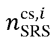
  • the terminal may obtain the maximum number of cyclic shifts n SRS cs ,max based on the transmission comb number K TC , and determine the resource mapping mode of the SRS based on n SRS cs ,max .
  • the terminal determine a grouping mode of the SRS ports and/or the resource mapping mode based on the number N ap SRS of the SRS ports and n SRS cs ,max .
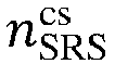
  • the cyclic shift configuration in the embodiment of the present disclosure mainly indicates a cyclic shift configuration value n SRS cs , that is, the cyclic shift configuration value is configured at a higher level.
  • the cyclic shift configuration includes a cyclic shift configuration value, or a serial number of the cyclic shift configuration value.
  • the cyclic shift configuration value n SRS cs is a cyclic shift configuration value corresponding to the SRS resource, and is used to determine the cyclic shifts corresponding to the SRS sequences of all of the antenna ports included in the SRS resource.
  • the resource mapping mode information includes one of the following:
  • the plurality of SRS ports of an SRS resource are mapped to a plurality of time domain resource groups and/or a plurality of frequency domain resource groups
  • the plurality of SRS ports of the SRS resources are mapped to the plurality of time domain resource groups and/or the plurality of frequency domain resource groups (e.g., two time domain resource groups and two frequency domain resource groups).
  • the mapping of the antenna ports to the plurality of time domain resource groups and/or the plurality of frequency domain resource groups is indicated by indication information.
  • the resource mapping mode information includes the indication information which indicates that the antenna ports are mapped to the plurality of time domain resource groups and/or the plurality of frequency domain resource groups.
  • the indication information indicating that the antenna ports are mapped to the plurality of time domain resource groups and/or the plurality of frequency domain resource groups includes: time domain and/or frequency domain position information corresponding to the plurality of time domain resource groups and/or the plurality of frequency domain resource groups to which the antenna ports are mapped.
  • the time domain and/or frequency domain position information includes a time domain offset between the plurality of time domain resource groups.
  • the time domain and/or frequency domain position information includes a frequency domain offset between the plurality of frequency domain resource groups.
  • the system supports a plurality of resource mapping modes of the SRS resources, and the index identifies one of the resource mapping modes.
  • the resource mapping mode in the embodiment of the present disclosure refers to a mapping relationship between the antenna port and the resource.
  • a grouping mode of the antenna ports e.g., grouped into 2 groups or 4 groups
  • the number of the antenna ports included in a group etc.
  • one resource mapping mode may be indicated by the index.
  • one possible mode is as follows: an alternative resource mapping mode corresponding to the index is that all of the SRS ports are mapped to the same time-frequency resource; and an alternative resource mapping mode is that the N ap SRS SRS ports are mapped to 2 groups of frequency domain resources.
  • one resource mapping mode may be indicated by the index, where an alternative resource mapping mode is that all of the SRS ports are mapped to the same time-frequency resource; an alternative resource mapping mode is that the N ap SRS SRS ports include 2 groups mapped to 2 groups of frequency domain resources.
  • the first information obtained by the terminal may be determined based on the configuration of the network device; for example, if the configuration information sent by the network device includes information indicative of the first information, the terminal may determine the first information based on the information indicative of the first information.
  • the method further includes: according to the first information, determining at least one of a grouping of the N ap SRS antenna ports, the SRS sequence corresponding to each of the N ap SRS antenna ports, and the time domain resource and/or the frequency domain resource to which each of the N ap SRS antenna ports is mapped.
  • the grouping of the N ap SRS antenna ports is determined according to the first information.
  • the SRS sequence corresponding to each of the N ap SRS antenna ports is determined according to the first information.
  • the time domain resource and/or the frequency domain resource to which each of the N ap SRS antenna ports is mapped is determined according to the first information; optionally, the time domain resources to which each antenna port in the N ap SRS antenna ports is mapped is determined according to the first information; optionally, the frequency domain resource to which each of the N ap SRS antenna ports is mapped is determined according to the first information; optionally, the time domain resources and the frequency domain resource to which each of the N ap SRS antenna ports is mapped are determined according to the first information.
  • the grouping of the N ap SRS antenna ports and the SRS sequence corresponding to each of the N ap SRS antenna ports are determined according to the first information.
  • the SRS sequence corresponding to each of the N ap SRS antenna ports and the time domain resource and/or the frequency domain resource to which each of the N ap SRS antenna ports is mapped are determined according to the first information.
  • the terminal determines at least one of the grouping of the N ap SRS antenna ports, the SRS sequence corresponding to each of the N ap SRS antenna ports, and the time domain resource and/or the frequency domain resource to which each of the N ap SRS antenna ports is mapped, so as to send the SRS.
  • the method further includes:
  • the corresponding relationship in the embodiment of the present disclosure may be appointed by a protocol or indicated by a network device. That is, the network device determines a corresponding relationship firstly, and then sends the corresponding relationship to the terminal.
  • the method before the transmitting an SRS corresponding to the SRS resource, the method further includes:
  • a cyclic shift offset value corresponding to a first port is calculated based on one of the above formulas
  • a cyclic shift offset value corresponding to a second port is calculated based on the other of the above formulas
  • the first port and the second port are different antenna ports of the N ap SRS antenna ports. That is, one part of the N ap SRS antenna ports are corresponding to one calculation formula of the cyclic shift offset value nSRS, and the other part of the N ap SRS antenna ports are corresponding to another calculation formula of n SRS cs , i .
  • the first port and the second port are mapped to different resources.
  • the resources are time domain resources, or frequency domain resources, or time-frequency resources (i.e., time domain resources and frequency domain resources). That is, optionally, antenna ports using the same calculation formula of n SRS cs , i among the N ap SRS antenna ports are mapped to the same resource, and antenna ports using different calculation formulas of n SRS cs , i are mapped to different resources.
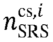
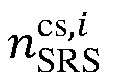
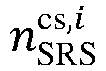
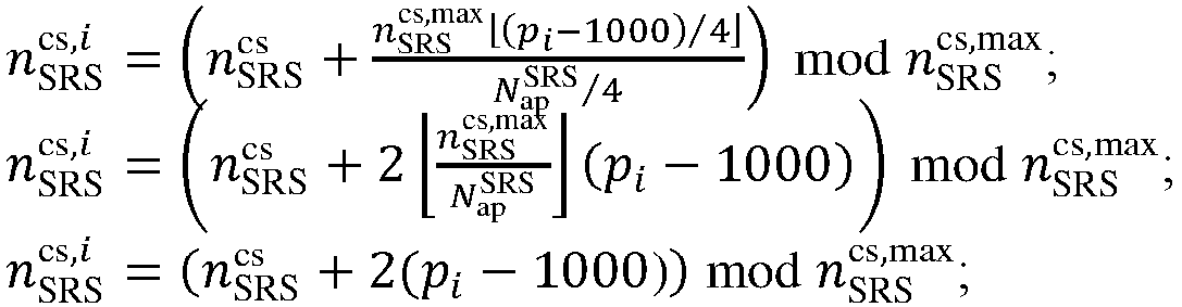
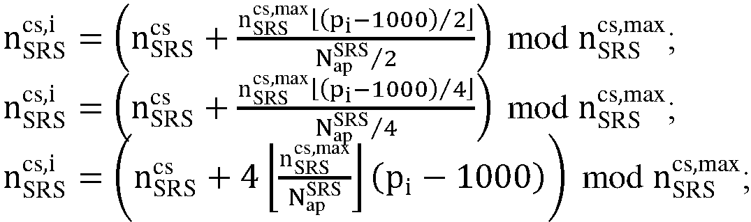
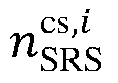
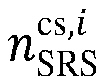
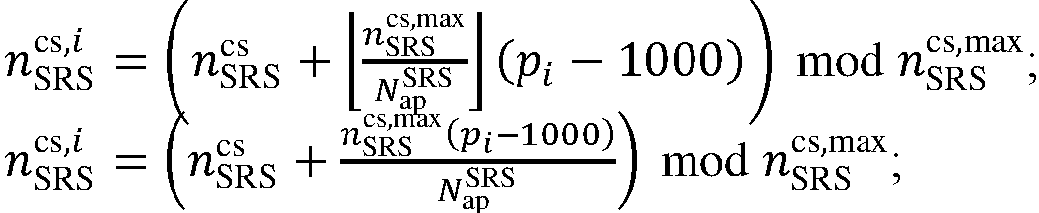
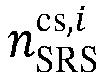
  • the determination mode of determining the cyclic shift offset value n SRS cs , i corresponding to the SRS sequence which is corresponding to the antenna port with the index of i among the N ap SRS antenna ports may be of one or more of:
  • the corresponding first formula is determined based on one or more of the maximum number of cyclic shifts, the cyclic shift configuration value, or the transmission comb number.
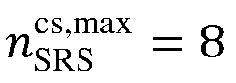
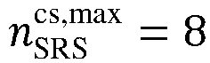
  • n SRS cs ,max 8
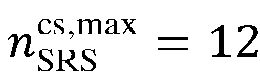
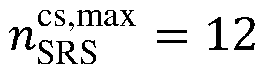
  • n SRS cs ,max 12
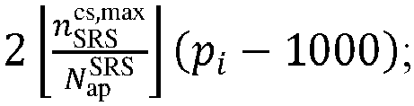
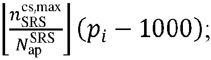
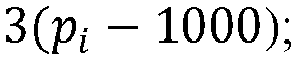
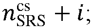
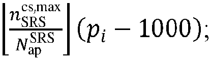
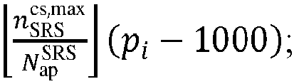
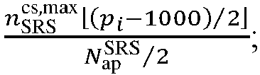
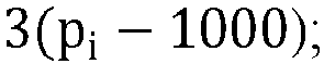
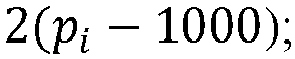
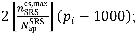
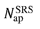
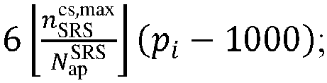
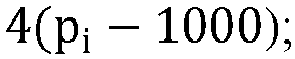
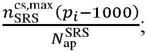
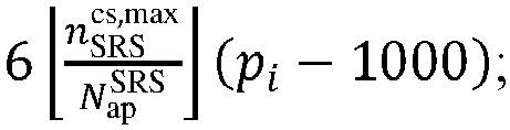
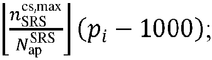
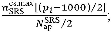
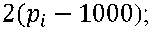
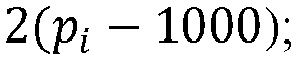
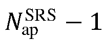
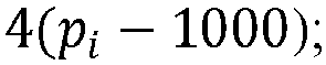
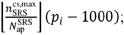
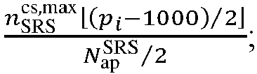
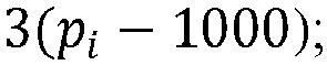
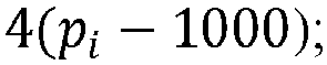
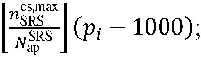
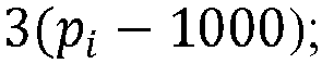
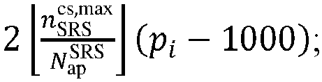
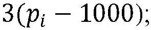
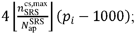
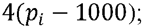
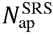
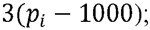
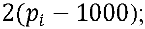
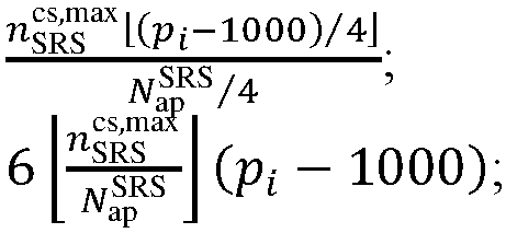
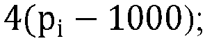
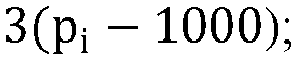
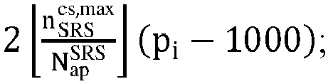
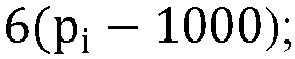
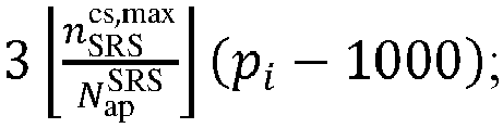
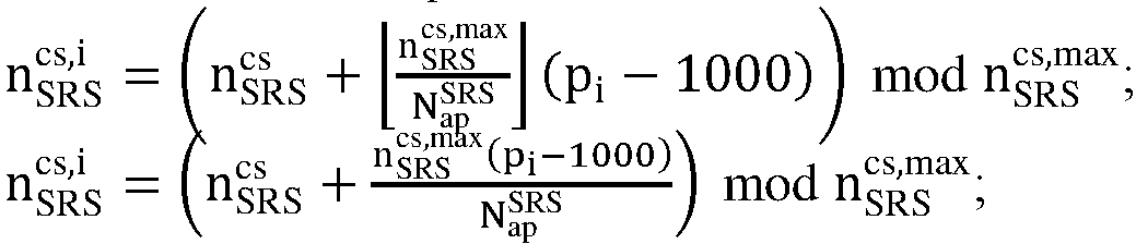
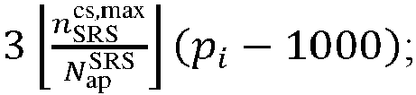
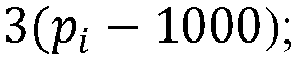
  • the cyclic shift offset value n SRS cs , i corresponding to the SRS sequence which is corresponding to the antenna port with the index of i among the N ap SRS antenna ports is determined based on at least one of: n SRS cs ,max N ap SRS p i ⁇ 1000 ; n SRS cs ,max p i ⁇ 1000 N ap SRS ; n SRS cs + p i ⁇ 1000 ; n SRS cs + i ; n SRS cs ,max p i ⁇ 1000 / 2 N ap SRS / 2 ; 3 n SRS cs ,max N ap SRS p i ⁇ 1000 ; 3 p i ⁇ 1000 ; 2 n SRS cs ,max N ap SRS p i ⁇ 1000 ; 3 p i ⁇ 1000 ;
  • the corresponding second formula is determined based on one or more of the maximum number of cyclic shifts, the cyclic shift configuration value, or the transmission comb number.
  • n SRS cs ,max 12
  • n SRS cs ,max 6
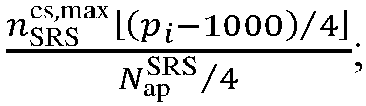
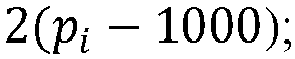
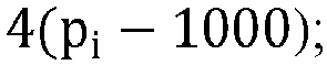
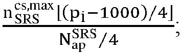
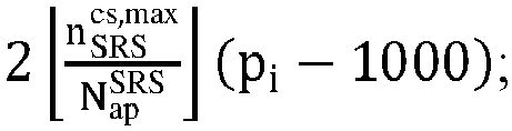
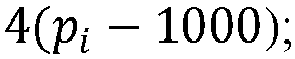
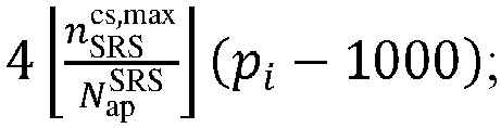
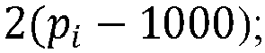
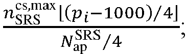
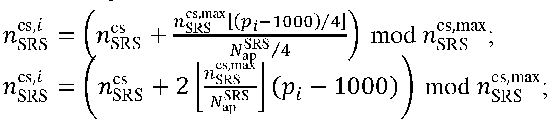
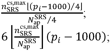
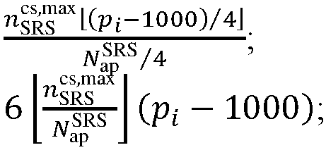
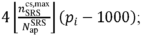
  • the cyclic shift offset value n SRS cs , i corresponding to the SRS sequence which is corresponding to the antenna port with the index of i among the N ap SRS antenna ports is determined based on at least one of: n SRS cs ,max p i ⁇ 1000 / 4 N ap SRS / 4 ; 2 n SRS cs ,max N ap SRS p i ⁇ 1000 ; 2 p i ⁇ 1000 ; 2i; n SRS cs ,max N ap SRS p i ⁇ 1000 ; n SRS cs + p i ⁇ 1000 ; n SRS cs + i ; 4 n SRS cs ,max N ap SRS p i ⁇ 1000 ; 4 p i
  • the corresponding third formula is determined based on one or more of the maximum number of cyclic shifts, the cyclic shift configuration value, or the transmission comb number.
  • n SRS cs ,max 6
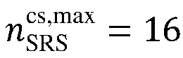
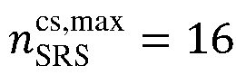
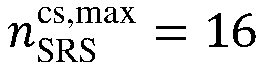
  • n SRS cs ,max 16
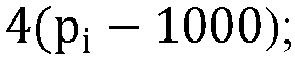
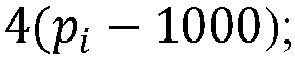
  • the cyclic shift offset value n SRS cs , i corresponding to the SRS sequence which is corresponding to the antenna port with the index of i among the N ap SRS antenna ports is determined based on at least one of: 4 p i ⁇ 1000 ; 4i; 2 n SRS cs ,max N ap SRS p i ⁇ 1000 ; 2 p i ⁇ 1000 ; 2i; n SRS cs ,max N ap SRS p i ⁇ 1000 ; n SRS cs ,max N ap SRS p i ⁇ 1000 ; n SRS cs + p i ⁇ 1000 ; n SRS cs + i ; n SRS cs + i ; n SRS cs ,max p i ⁇ 1000 / 2 N ap SRS
  • the corresponding fourth formula is determined based on one or more of the maximum number of cyclic shifts, the cyclic shift configuration value, or the transmission comb number.
  • n SRS cs ,max 16
  • the cyclic shift offset value n SRS cs , i corresponding to the SRS sequence which is corresponding to the antenna port with the index of i among the N ap SRS antenna ports is determined based on at least one of: n SRS cs ,max N ap SRS p i ⁇ 1000 ; n SRS cs + p i ⁇ 1000 ; n SRS cs + i ; 3 n SRS cs ,max N ap SRS p i ⁇ 1000 ; 3 p i ⁇ 1000 ; 3i; 2 n SRS cs ,max N ap SRS p i ⁇ 1000 ; 2 p i ⁇ 1000 ; 2i; 4 n SRS cs ,max N ap SRS p i ⁇ 1000 ; 4 p i ⁇ 1000 ; 4i; n SRS cs ,max N ap SRS p i ⁇ 1000
  • the corresponding fifth formula is determined based on one or more of the maximum number of cyclic shifts, the cyclic shift configuration value, or the transmission comb number.
  • n SRS cs limits the obtaining mode of n SRS cs , i under different values of n SRS cs ,max
  • implementation 5 does not distinguish the values of n SRS cs ,max , i.e., the obtaining formula of n SRS cs , i used under different values of n SRS cs ,max may be the same or different.
  • the antenna ports in different antenna port groups adopt different formulas to determine the cyclic shift offset value.
  • the sequences corresponding to the N ap SRS antenna ports are determined based on one or more of the maximum number of cyclic shifts, the number of the antenna ports N ap SRS , or the cyclic shift configuration value.
  • the cyclic shift offset values corresponding to the N ap SRS antenna ports may be determined based on one or more of the maximum number of cyclic shifts, the number of the antenna ports N ap SRS , or the cyclic shift configuration value, and the SRS sequence may be determined based on the cyclic shift offset values.
  • all of the antenna ports adopt the same calculation formula of the cyclic shift offset value.
  • the number of the antenna ports N ap SRS and the cyclic shift configuration value are given (or predetermined, or designated)
  • all of the antenna ports in the same SRS resource adopt the same calculation formula of the cyclic shift offset value.
  • the same number of the antenna ports N ap SRS and different cyclic shift configuration values
  • at least part of the antenna ports included in the two SRS resources adopt different calculation formulas of the cyclic shift offset value.
  • the transmitting an SRS corresponding to the SRS resource includes:
  • the implementation of the determining a starting position of a frequency domain resource to which the SRS sequence corresponding to the antenna port with the index of i is mapped, according to the position parameter k TC p i of the frequency domain resource may be one or more of the following.
  • the corresponding sixth formula is determined based on one or more of the maximum number of cyclic shifts, the cyclic shift configuration value, or the transmission comb number.
  • n SRS cs ,max 8
  • k TC p i k ⁇ TC + 2 K TC / 4 mod K TC .
  • the corresponding seventh formula is determined based on one or more of the maximum number of cyclic shifts, the cyclic shift configuration value, or the transmission comb number.
  • n SRS cs ,max 12
  • Implementation 3 the position parameter k TC p i of the frequency domain resource corresponding to the antenna port with the index of i among the N ap SRS antenna ports is determined based on at least one of: k ⁇ TC + 3 ; k ⁇ TC + 2 ; k ⁇ TC + 1 ; k ⁇ TC + 3 K TC / 4 ; k ⁇ TC + K TC / 4 ; k ⁇ TC + 4 .
  • the corresponding eighth formula is determined based on one or more of the maximum number of cyclic shifts, the cyclic shift configuration value, or the transmission comb number.
  • k TC may be determined based on the configuration information of the SRS resource.
  • the configuration information carries k TC .
  • implementation 1 and the implementation 2 described above limit the obtaining mode of k TC p i under different values of n SRS cs ,max , and the implementation 3 does not distinguish the values of n SRS cs ,max , i.e., k TC p i may be obtained using the same or different formulas under different values of n SRS cs ,max .
  • the antenna ports in different antenna port groups adopt different formulas to determine the position parameter of the frequency domain resource.
  • a starting position of a frequency domain resource corresponding to the N ap SRS antenna ports is determined based on one or more of the maximum number of cyclic shifts, the number of the antenna ports N ap SRS , or the cyclic shift configuration value.
  • a position parameter of a frequency domain resource corresponding to the N ap SRS antenna ports may be determined based on one or more of the maximum number of cyclic shifts, the number of the antenna ports N ap SRS , or the cyclic shift configuration value, and a starting position of the frequency domain resource may be further determined based on the cyclic shift configuration value.
  • all of the antenna ports adopt the same calculation formula of the position parameter of the frequency domain resource.
  • all of the antenna ports in the same SRS resource adopt the same calculation formula of the position parameter of the frequency domain resource.
  • the same number of the antenna ports N ap SRS and different cyclic shift configuration values
  • at least part of the antenna ports included in the two SRS resources adopt different calculation formulas of the position parameter of the frequency domain resource.
  • a starting position of a frequency domain resource is corresponding to the position parameter k TC p i of the frequency domain resource, which includes: determining a starting position of a frequency domain resource based on the position parameter k TC p i of the frequency domain resource.
  • N ap SRS 8 as an example, the obtaining mode of k TC p i and n SRS cs , i in at least one embodiment of the present disclosure is illustrated as follows.
  • n SRS cs ,max 8 or 12; the antenna ports are equally grouped into two groups
  • transmissions of all of the antenna ports of the SRS are at the same frequency domain position.
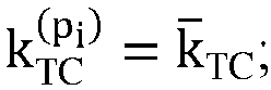
  • a frequency domain transmission position of the SRS is obtained based on k TC p i .
  • k TC p i k ⁇ TC .
  • this solution is applicable to a case where K TC is valued as 8, 4 or 2.
  • the transmissions of all of the antenna ports of the SRS are at the same time domain position.
  • the starting position of the frequency domain resource of the SRS is obtained based on k TC p i .
  • k TC p i specifically may be obtained using one of the following cases:
  • k TC and K TC are determined based on the configuration information of the SRS resource; optionally, n SRS cs ,max is determined based on a parameter used to determine K TC in the configuration information of the SRS resource, and for example, n SRS cs ,max is determined based on K TC .
  • this solution is applicable to a case where K TC is valued as 8, 4 or 2.
  • n SRS cs ,max 12 ; the antenna ports are equally grouped into two groups
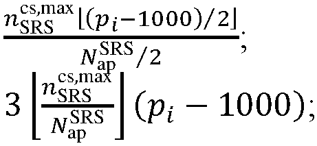
  • n SRS cs , i n SRS cs + n SRS cs ,max p i ⁇ 1000 / 2 N ap SRS / 2 mod n SRS cs ,max ;
  • n SRS cs , i n SRS cs + 3 n SRS cs ,max N ap SRS p i ⁇ 1000 mod n SRS cs ,max ;
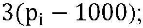
  • n SRS cs , i n SRS cs + 3 p i ⁇ 1000 mod n SRS cs ,max ;
  • n SRS cs , i n SRS cs + 3 p i ⁇ 1000 mod n SRS cs ,max ;
  • n SRS cs , i n SRS cs + 3 p i ⁇ 1000 mod n SRS cs ,max ;
  • the starting position of the frequency domain resource of the SRS is obtained based on k TC p i that specifically may be obtained using one of the following cases:
  • the starting position of the frequency domain resource of the SRS is obtained based on . that specifically may be obtained using one of the following cases:
  • this solution is applicable to a case where K TC is valued as 8, 4 or 2.
  • n SRS cs ,max 12 ; the antenna ports are equally grouped into four groups
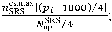
  • n SRS cs , i n SRS cs + n SRS cs ,max p i ⁇ 1000 / 4 N ap SRS / 4 mod n SRS cs ,max ;
  • n SRS cs , i n SRS cs + n SRS cs ,max p i ⁇ 1000 / 2 N ap SRS / 2 mod n SRS cs ,max ;
  • n SRS cs , i n SRS cs + 2 n SRS cs ,max N ap SRS p i ⁇ 1000 mod n SRS cs ,max ;
  • n SRS cs , i n SRS cs + 2 n SRS cs ,max N ap SRS p i ⁇ 1000 mod n SRS cs ,max ;
  • k TC and K TC are determined based on the configuration information of the SRS resource; optionally, n SRS cs ,max is determined based on a parameter used to determine K TC in the configuration information of the SRS resource, and for example, n SRS cs ,max is determined based on K TC .
  • this solution is applicable to a case where K TC is valued as 8 or 4.
  • n SRS cs ,max 12 ; the antenna ports are equally grouped into four groups
  • the starting position of the frequency domain resource of the SRS is obtained based on k TC p i that specifically may be obtained using one of the following cases:
  • k TC and K TC are determined based on the configuration information of the SRS resource; optionally, n SRS cs ,max is determined based on a parameter used to determine K TC in the configuration information of the SRS resource, and for example, n SRS cs ,max is determined based on K TC .
  • this solution is applicable to a case where K TC is valued as 8 or 4.
  • n SRS cs ,max 12 ; the antenna ports are equally grouped into four groups
  • n SRS cs , i n SRS cs + n SRS cs ,max p i ⁇ 1000 / 2 N ap SRS / 2 mod n SRS cs ,max ;
  • n SRS cs , i n SRS cs + 3 n SRS cs ,max N ap SRS p i ⁇ 1000 mod n SRS cs ,max ;
  • n SRS cs , i n SRS cs + 3 p i ⁇ 1000 mod n SRS cs ,max ;
  • n SRS cs , i n SRS cs + 3 p i ⁇ 1000 mod n SRS cs ,max ;
  • n SRS cs , i n SRS cs + 3 p i ⁇ 1000 mod n SRS cs ,max ;
  • the starting position of the frequency domain resource of the SRS is obtained based on . that specifically may be obtained using one of the following cases:
  • k TC and K TC are determined based on the configuration information of the SRS resource; optionally, n SRS cs ,max is determined based on a parameter used to determine K TC in the configuration information of the SRS resource, and for example, n SRS cs ,max is determined based on K TC .
  • this solution is applicable to a case where K TC is valued as 8 or 4.
  • n SRS cs ,max 8 ; the antenna ports are equally grouped into four groups
  • n SRS cs , i n SRS cs + n SRS cs , max p i ⁇ 1000 / 4 N sp SRS / 4 mod n SRS cs , max ;
  • n SRS cs , i n SRS cs + n SRS cs , max p i ⁇ 1000 / 2 N ap SRS / 2 mod n SRS cs , max ;
  • n SRS cs , i n SRS cs + n SRS cs , max N ap SRS p i ⁇ 1000 mod n SRS cs , max ;
  • n SRS cs , i n SRS cs + n SRS cs , max N ap SRS p i ⁇ 1000 mod n SRS cs , max ;
  • n SRS cs , i n S
  • the starting position of the frequency domain resource of the SRS is obtained based on k TC p i .
  • k TC p i specifically may be obtained using one of the following cases:
  • k TC and K TC are determined based on the configuration information of the SRS resource; optionally, n SRS cs ,max is determined based on a parameter used to determine K TC in the configuration information of the SRS resource, and for example, n SRS cs ,max is determined based on K TC .
  • this solution is applicable to a case where K TC is valued as 8 or 4.
  • the starting position of the frequency domain resource of the SRS is obtained based on k TC p i that specifically may be obtained using one of the following cases:
  • k TC and K TC are determined based on the configuration information of the SRS resource; optionally, n SRS cs ,max is determined based on a parameter used to determine K TC in the configuration information of the SRS resource, and for example, n SRS cs ,max is determined based on K TC .
  • this solution is applicable to a case where K TC is valued as 8, 4 or 2.
  • n SRS cs ,max 8 ; the antenna ports are equally grouped into four groups
  • n SRS cs , i n SRS cs + n SRS cs ,max p i ⁇ 1000 / 2 N ap SRS / 2 mod n SRS cs , max ;
  • n SRS cs , i n SRS cs + 2 n SRS cs , max N ap SRS p i ⁇ 1000 mod n SRS cs , max ;
  • n SRS cs , i n SRS cs + 2 p i ⁇ 1000 mod n SRS cs , max ;
  • n SRS cs , i n SRS cs + 2 p i ⁇ 1000 mod n SRS cs , max ;
  • n SRS cs , i n SRS cs + 2 p i ⁇ 1000 mod n SRS cs , max ;
  • the starting position of the frequency domain resource of the SRS is obtained based on k TC p i that specifically may be obtained using one of the following cases:
  • k TC and K TC are determined based on the configuration information of the SRS resource; optionally, n SRS cs ,max is determined based on a parameter used to determine K TC in the configuration information of the SRS resource, and for example, n SRS cs ,max is determined based on K TC .
  • this solution is applicable to a case where K TC is valued as 8, 4 or 2.
  • n SRS cs ,max 8 ; the antenna ports are equally grouped into two groups
  • the starting position of the frequency domain resource of the SRS is obtained based on k TC p i that specifically may be obtained using one of the following cases:
  • k TC and K TC are determined based on the configuration information of the SRS resource; optionally, n SRS cs ,max is determined based on a parameter used to determine K TC in the configuration information of the SRS resource, and for example, n SRS cs ,max is determined based on K TC .
  • the processor reads the computer program in the memory and performs one of operations of:
  • the sequence generation parameter of the SRS includes at least one of a maximum number of cyclic shifts and a cyclic shift configuration.
  • an obtaining mode of the maximum number of cyclic shifts includes:
  • the resource mapping mode information includes one of the following:
  • the grouping information of the N ap SRS antenna ports includes the number of the groups, which includes at least one of:
  • the processor reads the computer program in the memory and performs operations of:
  • the processor reads the computer program in the memory and performs operations of:
  • the processor reads the computer program in the memory and performs operations of:
  • the processor reads the computer program in the memory and performs operations of:
  • the processor reads the computer program in the memory and performs operations of:
  • the antenna ports in different antenna port groups adopt different formulas to determine the cyclic shift offset value.
  • the processor reads the computer program in the memory and performs operations of:
  • the processor reads the computer program in the memory and performs operations of:
  • the processor reads the computer program in the memory and performs operations of:
  • the antenna ports in different antenna port groups adopt different formulas to determine the cyclic shift offset value.
  • the N ap SRS is valued as 8.
  • At least one embodiment of the present disclosure further provides a terminal device, including a memory, a processor, and a computer program stored in the memory and runnable in the processor, where when executing the program, the processor implements each process in the embodiment of the information transmission method applied to the terminal device, and achieves the same technical effect, which will be omitted here to avoid repetition.
  • a terminal device including a memory, a processor, and a computer program stored in the memory and runnable in the processor, where when executing the program, the processor implements each process in the embodiment of the information transmission method applied to the terminal device, and achieves the same technical effect, which will be omitted here to avoid repetition.
  • At least one embodiment of the present disclosure further provides a computer-readable storage medium which stores a computer program, where when executed by a processor, the program implements each process in the embodiment of the information transmission method applied to the terminal device, and achieves the same technical effect, which will be omitted here to avoid repetition.
  • the computer-readable storage medium for example may be a Read-Only Memory (ROM), a Random Access Memory (RAM), a magnetic disk or an optical disk.
  • an embodiment of the present disclosure provides an information transmission method performed by a network device, including:
  • the N ap SRS antenna ports include a plurality of antenna port groups, and the method further includes: determining at least one of a grouping of the N ap SRS antenna ports, the SRS sequence corresponding to each of the N ap SRS antenna ports, and the time domain resource and/or the frequency domain resource to which each of the N ap SRS antenna ports is mapped, based on a sequence generation parameter of the SRS.
  • the sequence generation parameter of the SRS includes at least one of a maximum number of cyclic shifts and a cyclic shift configuration.
  • the N ap SRS antenna ports include a plurality of antenna port groups each corresponding to one group of time domain resources and/or frequency domain resources.
  • the method before the receiving an SRS corresponding to the configuration information and a transmission rule, the method further includes:
  • the grouping of the N ap SRS antenna ports satisfies at least one of the following:
  • the cyclic shift offset values corresponding to the SRS sequences which are corresponding to the antenna ports included in different antenna port groups among the plurality of antenna port groups are the same.
  • the grouping of the N ap SRS antenna ports satisfies one of the following:
  • the method further includes: determining information indicative of the first information based on at least one of a grouping mode of the N ap SRS antenna ports, the SRS sequence corresponding to each of the N ap SRS antenna ports, and the time domain resource and/or the frequency domain resource to which each of the N ap SRS antenna ports is mapped.
  • the network device sends the information indicative of the first information to the terminal.
  • the configuration information includes information indicative of the first information. That is, the network device sends the information indicative of the first information to the terminal.
  • the information indicative of the first information is determined based on the first information.
  • the sequence generation parameter of the SRS includes at least one of a maximum number of cyclic shifts and a cyclic shift configuration.
  • an obtaining mode of the maximum number of cyclic shifts includes:
  • the resource mapping mode information includes at least one of:
  • the grouping information of the N ap SRS antenna ports includes the number of the groups, which includes at least one of:
  • the method further includes at least one of the following:
  • the network device After obtaining the above corresponding relationship, the network device sends the corresponding relationship to the terminal.
  • the grouping of the antenna ports is determined based on the number of the antenna ports and the fact that there is a corresponding relationship between the number of the antenna ports and the antenna port groups.
  • the sequence generation parameter or the grouping of the antenna ports is determined based on the fact that there is a corresponding relationship between the sequence generation parameter and the antenna port groups.
  • the antenna port groups are determined, and the number of the groups is determined based on the corresponding relationship between the number of the groups and the antenna port groups.
  • the method before the receiving an SRS corresponding to the configuration information and a transmission rule, the method further includes:
  • the method before the receiving an SRS corresponding to the configuration information and a transmission rule, the method further includes:
  • the method before the receiving an SRS corresponding to the configuration information and a transmission rule, the method further includes:
  • the method before the receiving an SRS corresponding to the configuration information and a transmission rule, the method further includes:
  • the method before the receiving an SRS corresponding to the configuration information and a transmission rule, the method further includes:
  • the network device indicates indication information of a formula for determining n SRS cs , i to the terminal.
  • the terminal receives the indication information and determines n SRS cs , i based on the indication information.
  • the antenna ports in different antenna port groups adopt different formulas to determine the cyclic shift offset value.
  • the receiving an SRS corresponding to the configuration information and a transmission rule includes:
  • the receiving an SRS corresponding to the configuration information and a transmission rule includes:
  • the receiving an SRS corresponding to the configuration information and a transmission rule includes:
  • the antenna ports in different antenna port groups adopt different formulas to determine the cyclic shift offset value.
  • the N ap SRS is valued as 8.
  • the network device indicates indication information of a formula for determining n SRS cs , i to the terminal.
  • the terminal receives the indication information and determines n SRS cs , i based on the indication information.
  • the network device determines and receives the SRS sequence in the same way as the terminal device determines and sends the SRS sequence. Any description in the above embodiments is applicable to the embodiments of the information transmission method applied to the side of the network device, and the same technical effects can be achieved.
  • an embodiment of the present disclosure further provides an information transmission apparatus 600 applied to a network device, including:
  • the N ap SRS antenna ports include a plurality of antenna port groups each corresponding to one group of time domain resources and/or frequency domain resources.
  • the apparatus before the second reception unit 602 receives the SRS corresponding to the configuration information and the transmission rule, the apparatus further includes:
  • the grouping of the N ap SRS antenna ports satisfies at least one of the following:
  • the cyclic shift offset values corresponding to the SRS sequences which are corresponding to the antenna ports included in different antenna port groups among the plurality of antenna port groups are the same.
  • the grouping of the N ap SRS antenna ports satisfies one of the following:
  • the configuration information includes information indicative of and determined based on the first information.
  • the sequence generation parameter of the SRS includes at least one of a maximum number of cyclic shifts and a cyclic shift configuration.
  • an obtaining mode of the maximum number of cyclic shifts includes:
  • the resource mapping mode information includes one of the following:
  • e grouping information of the N ap SRS antenna ports includes the number of the groups, which includes at least one of:
  • the apparatus further includes at least one of:
  • the apparatus before the reception unit 602 receives the SRS corresponding to the configuration information and the transmission rule, the apparatus further includes:
  • the apparatus before the reception unit 602 receives the SRS corresponding to the configuration information and the transmission rule, the apparatus further includes:
  • the apparatus before the reception unit receives the SRS corresponding to the configuration information and the transmission rule, the apparatus further includes:
  • the apparatus before the reception unit receives the SRS corresponding to the configuration information and the transmission rule, the apparatus further includes:
  • the apparatus before the reception unit receives the SRS corresponding to the configuration information and the transmission rule, the apparatus further includes:
  • the antenna ports in different antenna port groups adopt different formulas to determine the cyclic shift offset value.
  • the reception unit 602 is configured to:
  • the reception unit 602 is configured to:
  • the reception unit 602 is configured to:
  • the antenna ports in different antenna port groups adopt different formulas to determine the cyclic shift offset value.
  • the N ap SRS is valued as 8.
  • any embodiment of the above information transmission method is applicable to the apparatus embodiments, and the same or similar advantageous effects can be achieved.
  • the division of the units in the embodiments of the present disclosure is schematic, which is only a division of logical functions, and there may be other division modes in practice.
  • various functional units in the embodiments of the present disclosure may be integrated into a processing unit, or physically existed separately, or two or more units may be integrated into one unit.
  • the integrated unit may be implemented in the form of hardware, or a software functional unit.
  • the integrated unit if implemented in the form of a software functional unit and sold or used as a separate product, may be stored in a processor-readable storage medium.
  • the computer software product is stored in a storage medium, and includes a plurality of instructions to cause a computer device (which may be a personal computer, a server, a network device, or the like) or a processor to perform all or part of the steps of the method described in various embodiments of the present disclosure.
  • the storage medium includes various media capable of storing program codes, such as a U disk, a mobile hard disk, a Read-Only Memory (ROM), a Random Access Memory (RAM), a magnetic disk, or an optical disk.
  • an embodiment of the present disclosure further provides a network device, including a processor 700, a transceiver 710, a memory 720, and a program stored in the memory 720 and runnable in the processor 700; where the transceiver 710 is connected to the processor 700 and the memory 720 through a bus interface, and where the processor 700 is configured to read the program in the memory and perform processes of:
  • a bus architecture may include any number of interconnected buses and bridges, and specifically various circuits of one or more processors represented by processor 700 and the memory represented by memory 720 are linked together.
  • the bus architecture may also link together various other circuits, such as a peripheral device, a voltage stabilizer, a power management circuit, etc., which are well known in the art and not further described herein.
  • the bus interface provides an interface.
  • the transceiver 710 may be composed of a plurality of elements, i.e., including a transmitter and a receiver, so as to provide units for communication with various other devices over a transmission medium including a wireless channel, a wired channel, a fiber optic cable, or the like.
  • the processor 700 is responsible for managing the bus architecture and general processing, and the memory 720 may store data used by the processor 700 in performing operations.
  • the processor 700 may be a Central Processing Unit (CPU), an Application Specific Integrated Circuit (ASIC), a Field-Programmable Gate Array (FPGA), or a Complex Programmable Logic Device (CPLD).
  • CPU Central Processing Unit
  • ASIC Application Specific Integrated Circuit
  • FPGA Field-Programmable Gate Array
  • CPLD Complex Programmable Logic Device
  • the processor may also adopt a multi-core architecture.
  • the N ap SRS antenna ports include a plurality of antenna port groups each corresponding to one group of time domain resources and/or frequency domain resources.
  • the processor 700 reads the computer program in the memory and performs processes of:
  • the grouping of the N ap SRS antenna ports satisfies at least one of the following:
  • the cyclic shift offset values corresponding to the SRS sequences which are corresponding to the antenna ports included in different antenna port groups among the plurality of antenna port groups are the same.
  • the grouping of the N ap SRS antenna ports satisfies one of the following:
  • the configuration information includes information indicative of and determined based on the first information.
  • the sequence generation parameter of the SRS includes at least one of a maximum number of cyclic shifts and a cyclic shift configuration.
  • an obtaining mode of the maximum number of cyclic shifts includes:
  • the resource mapping mode information includes one of the following:
  • the grouping information of the N ap SRS antenna ports includes the number of the groups, which includes at least one of:
  • the processor 700 reads the computer program in the memory and performs one of processes of:
  • the processor 700 reads the computer program in the memory and performs one of processes of:
  • the processor 700 reads the computer program in the memory and performs one of processes of:
  • the processor 700 reads the computer program in the memory and performs one of processes of:
  • the processor 700 reads the computer program in the memory and performs one of processes of:
  • the processor 700 reads the computer program in the memory and performs a process of:
  • the antenna ports in different antenna port groups adopt different formulas to determine the cyclic shift offset value.
  • the processor 700 reads the computer program in the memory and performs a process of:
  • the processor 700 reads the computer program in the memory and performs a process of:
  • the processor 700 reads the computer program in the memory and performs a process of:
  • the antenna ports in different antenna port groups adopt different formulas to determine the cyclic shift offset value.
  • the N ap SRS is valued as 8.
  • the embodiments of the present disclosure further provide a computer-readable storage medium which stores a computer program, where when executed by a processor, the computer program implements the steps of the information transmission method applied to a network device.
  • the computer-readable storage medium may be any available medium or data storage device accessible to the processor, including but not limited to, a magnetic storage (e.g., a floppy disk, a hard disk, a magnetic tape, Magneto-Optical (MO) disk, etc.), an optical storage (e.g., a Compact Disk (CD), a Digital Video Disk (DVD), a Blu-ray Disc (BD), a High-Definition Versatile Disc (HVD), etc.), and a semiconductor memory (e.g., a Read-Only Memory (ROM), an Erasable Programmable ROM (EPROM), an Electrically EPROM (EEPROM), an NAND FLASH, a Solid State Disk or Solid State Drive (SSD)), etc.
  • a magnetic storage e.g.,
  • an embodiment of the present disclosure may be provided as a method, a system, or a computer program product. Accordingly, the present disclosure may take the form of entirely hardware embodiments, entirely software embodiments, or embodiments combining software and hardware aspects. Moreover, the present disclosure may take the form of a computer program product embodied on one or more computer-usable storage media (including but not limited to a disk storage, an optical storage, etc.) containing computer-usable program codes.
  • These computer-executable instructions may be provided to a processor of a general-purpose computer, a special-purpose computer, an embedded processing machine or other programmable data processing device to produce a machine, such that the instructions executed by the processor of the computer or other programmable data processing device create means to realize function(s) specified in one or more flows of the flowchart and/or one or more blocks in the block diagram.
  • processor-executable instructions may also be stored in a processor-readable memory capable of guiding the computer or other programmable data processing device to work in a particular way, such that the instructions stored in the processor-readable memory can produce manufacture articles including an instructing device which realizes function(s) specified in one or more flows in the flowchart and/or one or more blocks in the block diagram.
  • processor-executable instructions may also be loaded onto a computer or other programmable data processing device, such that a series of operation steps can be performed on the computer or other programmable data processing device to produce a processing realized by the computer, thus the instructions executed on the computer or other programmable device provide step(s) for realizing function(s) specified in one or more flows in the flowchart and/or one or more blocks in the block diagram.
  • modules may be entirely or partially integrated into a physical entity, or physically separated.
  • these modules may all be implemented by calling software with a processing element; or all be implemented in the form of hardware; or some implemented by calling software with a processing element, and some implemented in the form of hardware.
  • a module may be a separately disposed processing element, or may be implemented by being integrated in a chip of the apparatus.
  • the module may also be stored in the form of program codes in a memory of the apparatus, and a processing element of the apparatus calls and executes the function of the module.
  • the implementations of other modules are similar.
  • all or part of these modules may be integrated together or independently implemented.
  • the processing element here may be an integrated circuit with a signal processing capability. During implementation, the steps of the above method or the above modules may be completed by a hardware integrated logical circuit in the processor element or instructions in the form of software.
  • modules, units, sub-units, or sub-modules may be one or more integrated circuits configured to implement the above methods, such as one or more Application Specific Integrated Circuits (ASICs), or one or more microprocessors (digital signal processors, DSPs), or one or more Field Programmable Gate Arrays, (FPGAs), etc.
  • ASICs Application Specific Integrated Circuits
  • DSPs digital signal processors
  • FPGAs Field Programmable Gate Arrays
  • the processing element may be a general-purpose processor, such as a Central Processing Unit (CPU) or any other processor capable of calling the program codes.
  • CPU Central Processing Unit
  • these modules may be integrated and implemented in the form of a System-On-a-Chip (SOC).
  • SOC System-On-a-Chip
  • a and/or B and/or C means that there are seven cases, i.e., A exists alone, B exists alone, C exists alone, both A and B exist, both B and C exist, both A and C exist, and A, B and C all exist.
  • a and/or B and/or C means that there are seven cases, i.e., A exists alone, B exists alone, C exists alone, both A and B exist, both B and C exist, both A and C exist, and A, B and C all exist.
  • “at least one of A and B" in the Specification and the claims should be understood as "A exists alone, B exists alone, or both A and B exist”.

Landscapes

  • Engineering & Computer Science (AREA)
  • Signal Processing (AREA)
  • Computer Networks & Wireless Communication (AREA)
  • Power Engineering (AREA)
  • Mobile Radio Communication Systems (AREA)

Abstract

An information transmission method and apparatus, a terminal device and a network device are provided, which relate to the technical field of communications. The information transmission method includes: receiving configuration information of a Sounding Reference Signal (SRS) resource; and transmitting an SRS corresponding to the SRS resource according to the configuration information and a transmission rule; where the SRS resource includes N ap SRS
Figure imga0001
antenna ports, and the transmission rule includes at least one of the following: cyclic shift offset values corresponding to SRS sequences which are corresponding to all or part of the antenna ports in the N ap SRS
Figure imga0002
antenna ports are continuous; the N ap SRS
Figure imga0003
antenna ports are mapped to at least two groups of time domain resources and/or frequency domain resources; or the N ap SRS
Figure imga0004
is an integer greater than 4.

Description

    CROSS REFERENCE OF RELATED APPLICATION
  • The present disclosure claims a priority of Chinese patent application No. 202210419154.9 filed on April 20, 2022 , which is incorporated herein by reference in its entirety.
  • TECHNICAL FIELD
  • The present disclosure relates to the field of communications, and in particular, to an information transmission method and apparatus, a terminal device and a network device.
  • BACKGROUND
  • In the New Radio (NR) system of the Third Generation Partnership Projects, 3GPP), the Sounding Reference Signal (SRS) may be used for the acquisition of uplink Channel State Information (CSI), the acquisition of downlink CSI, the beam management, etc. Since the uplink transmission supports at most four transmitting antennas, the system of the related art only supports SRS resources of 1, 2 or 4 antenna ports. With the increase of terminal types, some terminals can support up to 8 transmitting antennas.
  • When the sequence generation and resource mapping mode of the SRS resources in the related art is adopted, at least two antenna ports in the eight ports of the 8-port SRS resource use the same cyclic shift on the same time-frequency resource and then interfere with each other, which affects the performance.
  • SUMMARY
  • The embodiments of the present disclosure provide an information transmission method and apparatus, a terminal device, and a network device to solve the problem in the related art that due to the sequence generation and resource mapping mode of the SRS resources, the number of SRS ports accommodated in the same SRS resource on the same time domain resource is limited, such that at least two antenna ports in a plurality of ports of an SRS resource with multiple ports use the same cyclic shift on the same time-frequency resource and then interfere with each other, which affects the performance.
  • In order to solve the above technical problem, the embodiments of the present disclosure provide an information transmission method, including:
    • receiving configuration information of a Sounding Reference Signal (SRS) resource; and
    • transmitting an SRS corresponding to the SRS resource according to the configuration information and a transmission rule;
    • where the SRS resource includes N ap SRS
      Figure imgb0001
      antenna ports, and the transmission rule includes at least one of the following:
      • cyclic shift offset values corresponding to SRS sequences which are corresponding to all or part of the antenna ports in the N ap SRS
        Figure imgb0002
        antenna ports are continuous;
      • the N ap SRS
        Figure imgb0003
        antenna ports are mapped to at least two groups of time domain resources and/or frequency domain resources; or
      • the N ap SRS
        Figure imgb0004
        is an integer greater than 4.
  • Optionally, the N ap SRS
    Figure imgb0005
    antenna ports include a plurality of antenna port groups each corresponding to one group of time domain resources and/or frequency domain resources.
  • Optionally, before the transmitting an SRS corresponding to the SRS resource, the method further includes:
    • obtaining first information;
    • where the first information includes at least one of:
    • grouping information of the antenna ports;
    • a sequence generation parameter of the SRS; or
    • resource mapping mode information.
  • Optionally, the grouping of the N ap SRS
    Figure imgb0006
    antenna ports satisfies at least one of the following:
    • indexes of the antenna ports included in each of the antenna port groups are continuous; or
    • indexes of the antenna ports included in each of the antenna port groups are at an interval of a preset value.
  • Optionally, the cyclic shift offset values corresponding to the SRS sequences which are corresponding to the antenna ports included in different antenna port groups among the plurality of antenna port groups are the same.
  • Optionally, the grouping of the N ap SRS
    Figure imgb0007
    antenna ports satisfies one of the following:
    • the N ap SRS
      Figure imgb0008
      antenna ports are in one group;
    • the N ap SRS
      Figure imgb0009
      antenna ports are grouped equally; or
    • the N ap SRS
      Figure imgb0010
      antenna ports are grouped unequally.
  • Optionally, the configuration information includes information indicative of the first information.
  • Optionally, the sequence generation parameter of the SRS includes at least one of a maximum number of cyclic shifts and a cyclic shift configuration.
  • Optionally, the resource mapping mode information includes one of the following:
    • the antenna ports are mapped to one time domain resource group and/or one frequency domain resource group;
    • the antenna ports are mapped to a plurality of time domain resource groups and/or a plurality of frequency domain resource groups; or
    • an index of the resource mapping mode.
  • Optionally, after the obtaining the first information, the method further includes:
    according to the first information, determining at least one of a grouping of the N ap SRS
    Figure imgb0011
    antenna ports, the SRS sequence corresponding to each of the N ap SRS
    Figure imgb0012
    antenna ports, and the time domain resource and/or the frequency domain resource to which each of the N ap SRS
    Figure imgb0013
    antenna ports is mapped.
  • Optionally, the grouping information of the N ap SRS
    Figure imgb0014
    antenna ports includes the number of the groups, which includes at least one of:
    • the number of the antenna port groups;
    • the number of the time domain resource groups to which the SRS sequences are mapped; or
    • the number of the frequency domain resource groups to which the SRS sequences are mapped.
  • Optionally, the method further includes:
    • according to a corresponding relationship, determining at least one of a grouping of the N ap SRS
      Figure imgb0015
      antenna ports, the SRS sequence corresponding to each of the N ap SRS
      Figure imgb0016
      antenna ports, and the time domain resource and/or the frequency domain resource to which each of the N ap SRS
      Figure imgb0017
      antenna ports is mapped;
    • where the corresponding relationship includes at least one of:
    • a corresponding relationship between the number of the antenna ports and the antenna port groups;
    • a corresponding relationship between the sequence generation parameter and the antenna port groups; or
    • a corresponding relationship between the number of the groups and the antenna port groups.
  • Optionally, before the transmitting an SRS corresponding to the SRS resource, the method further includes:
    in a case where a maximum number of cyclic shifts corresponding to the SRS resource is n SRS cs ,max = 8
    Figure imgb0018
    , determining a cyclic shift offset value n SRS cs , i
    Figure imgb0019
    corresponding to the SRS sequence which is corresponding to an antenna port with an index of i among the N ap SRS
    Figure imgb0020
    antenna ports based on at least one of: n SRS cs ,max N ap SRS p i 1000 ;
    Figure imgb0021
    n SRS cs ,max p i 1000 N ap SRS ;
    Figure imgb0022
    n SRS cs + p i 1000 ;
    Figure imgb0023
    n SRS cs + i ;
    Figure imgb0024
    n SRS cs ,max p i 1000 / 2 N ap SRS / 2 ;
    Figure imgb0025
    n SRS cs ,max p i 1000 / 4 N ap SRS / 4 ;
    Figure imgb0026
    4 n SRS cs ,max N ap SRS p i 1000 ;
    Figure imgb0027
    4 p i 1000 ;
    Figure imgb0028
    4i; 2 n SRS cs ,max N ap SRS p i 1000 ;
    Figure imgb0029
    2 p i 1000 ;
    Figure imgb0030
    2i;
    • determining the SRS sequence which is corresponding to the antenna port with the index of i according to the cyclic shift offset value;
    • where pi is a port index of the antenna port with the index of i, and i is an integer less than or equal to N ap SRS 1
      Figure imgb0031
      .
  • Optionally, in a case where the maximum number of cyclic shifts corresponding to the SRS resource is n SRS cs ,max = 8
    Figure imgb0032
    , the cyclic shift offset value n SRS cs , i
    Figure imgb0033
    corresponding to the SRS sequence which is corresponding to the antenna port with the index of i among the N ap SRS
    Figure imgb0034
    antenna ports is determined based on at least one of: n SRS cs , i = n SRS cs + n SRS cs ,max N ap SRS p i 1000 mod n SRS cs ,max ;
    Figure imgb0035
    n SRS cs , i = n SRS cs + n SRS cs ,max p i 1000 N ap SRS mod n SRS cs ,max ;
    Figure imgb0036
    n SRS cs , i = n SRS cs + p i 1000 mod n SRS cs ,max ;
    Figure imgb0037
    n SRS cs , i = n SRS cs + i mod n SRS cs ,max ;
    Figure imgb0038
    n SRS cs , i = n SRS cs + n SRS cs ,max p i 1000 / 2 N ap SRS / 2 mod n SRS cs ,max ;
    Figure imgb0039
    n SRS cs , i = n SRS cs + n SRS cs ,max p i 1000 / 4 N ap SRS / 4 mod n SRS cs ,max ;
    Figure imgb0040
    n SRS cs ,i = n SRS cs + 4 n SRS cs ,max N ap SRS p i 1000 mod n SRS cs ,max ;
    Figure imgb0041
    n SRS cs ,i = n SRS cs + 4 p i 1000 mod n SRS cs ,max ;
    Figure imgb0042
    n SRS cs , i = n SRS cs + 4 i mod n SRS cs ,max ;
    Figure imgb0043
    n SRS cs , i = n SRS cs + 2 n SRS cs ,max N ap SRS p i 1000 mod n SRS cs ,max
    Figure imgb0044
    n SRS cs , i = n SRS cs + 2 p i 1000 mod n SRS cs ,max ;
    Figure imgb0045
    n SRS cs , i = n SRS cs + 2 i mod n SRS cs ,max ;
    Figure imgb0046

    where n SRS cs
    Figure imgb0047
    is a cyclic shift configuration value.
  • Optionally, before the transmitting an SRS corresponding to the SRS resource, the method further includes:
    in a case where a maximum number of cyclic shifts corresponding to the SRS resource is n SRS cs ,max = 12
    Figure imgb0048
    , determining a cyclic shift offset value n SRS cs , i
    Figure imgb0049
    corresponding to the SRS sequence which is corresponding to an antenna port with an index of i among the N ap SRS
    Figure imgb0050
    antenna ports based on at least one of: n SRS cs , max N ap SRS p i 1000 ;
    Figure imgb0051
    n SRS cs , max p i 1000 N ap SRS ;
    Figure imgb0052
    n SRS cs + p i 1000 ;
    Figure imgb0053
    n SRS cs + i ;
    Figure imgb0054
    n SRS cs , max p i 1000 / 2 N ap SRS / 2 ;
    Figure imgb0055
    3 n SRS cs , max N ap SRS p i 1000 ;
    Figure imgb0056
    3 p i 1000 ;
    Figure imgb0057
    3i; 2 n SRS cs , max N ap SRS p i 1000 ;
    Figure imgb0058
    2 p i 1000 ;
    Figure imgb0059
    2i; 4 n SRS cs , max N ap SRS p i 1000 ;
    Figure imgb0060
    4 p i 1000 ;
    Figure imgb0061
    4i; n SRS cs ,max p i 1000 / 4 N ap SRS / 4 ;
    Figure imgb0062
    6 n SRS cs ,max N ap SRS p i 1000 ;
    Figure imgb0063
    6 p i 1000 ;
    Figure imgb0064
    6i;
    • determining the SRS sequence which is corresponding to the antenna port with the index of i according to the cyclic shift offset value;
    • where pi is a port index of the antenna port with the index of i, and i is an integer less than or equal to N ap SRS 1
      Figure imgb0065
      .
  • Optionally, in a case where the maximum number of cyclic shifts corresponding to the SRS resource is n SRS cs ,max = 12
    Figure imgb0066
    , the cyclic shift offset value nSRS corresponding to the SRS sequence which is corresponding to the antenna port with the index of i among the N ap SRS
    Figure imgb0067
    antenna ports is determined based on at least one of: n SRS cs , i = n SRS cs + n SRS cs ,max N ap SRS p i 1000 mod n SRS cs ,max ;
    Figure imgb0068
    n SRS cs , i = n SRS cs + n SRS cs ,max p i 1000 N ap SRS mod n SRS cs ,max ;
    Figure imgb0069
    n SRS cs , i = n SRS cs + p i 1000 mod n SRS cs ,max ;
    Figure imgb0070
    n SRS cs , i = n SRS cs + i mod n SRS cs , max ;
    Figure imgb0071
    n SRS cs , i = n SRS cs + n SRS cs , max p i 1000 / 2 N ap SRS / 2 mod n SRS cs , max ;
    Figure imgb0072
    n SRS cs , i = n SRS cs + 3 n SRS cs , max N ap SRS p i 1000 mod n SRS cs , max ;
    Figure imgb0073
    n SRS cs , i = n SRS cs + 3 p i 1000 mod n SRS cs , max ;
    Figure imgb0074
    n SRS cs , i = n SRS cs + 3 i mod n SRS cs , max ;
    Figure imgb0075
    n SRS cs , i = n SRS cs + 2 n SRS cs , max N ap SRS p i 1000 mod n SRS cs , max ;
    Figure imgb0076
    n SRS cs , i = n SRS cs + 2 p i 1000 mod n SRS cs , max ;
    Figure imgb0077
    n SRS cs , i = n SRS cs + 2 i mod n SRS cs , max ;
    Figure imgb0078
    n SRS cs , i = n SRS cs + 4 n SRS cs , max N ap SRS p i 1000 mod n SRS cs , max ;
    Figure imgb0079
    n SRS cs , i = n SRS cs + 4 p i 1000 mod n SRS cs , max ;
    Figure imgb0080
    n SRS cs , i = n SRS cs + 4 i mod n SRS cs ,max ;
    Figure imgb0081
    n SRS cs , i = n SRS cs + n SRS cs ,max p i 1000 / 4 N ap SRS / 4 mod n SRS cs ,max ;
    Figure imgb0082
    n SRS cs , i = n SRS cs + 6 n SRS cs ,max N ap SRS p i 1000 mod n SRS cs ,max ;
    Figure imgb0083
    n SRS cs , i = n SRS cs + 6 p i 1000 mod n SRS cs ,max ;
    Figure imgb0084
    n SRS cs , i = n SRS cs + 6 i mod n SRS cs ,max ;
    Figure imgb0085
    where n SRS cs
    Figure imgb0086
    is a cyclic shift configuration value.
  • Optionally, before the transmitting an SRS corresponding to the SRS resource, the method further includes:
    in a case where a maximum number of cyclic shifts corresponding to the SRS resource is n SRS cs ,max = 6
    Figure imgb0087
    , determining a cyclic shift offset value n SRS cs , i
    Figure imgb0088
    corresponding to the SRS sequence which is corresponding to an antenna port with an index of i among the N ap SRS
    Figure imgb0089
    antenna ports based on at least one of: n SRS cs ,max p i 1000 / 4 N ap SRS / 4 ;
    Figure imgb0090
    2 n SRS cs ,max N ap SRS p i 1000 ;
    Figure imgb0091
    2 p i 1000 ;
    Figure imgb0092
    2i; n SRS cs ,max N ap SRS p i 1000 ;
    Figure imgb0093
    n SRS cs + p i 1000 ;
    Figure imgb0094
    n SRS cs + i ;
    Figure imgb0095
    4 n SRS cs ,max N ap SRS p i 1000 ;
    Figure imgb0096
    4 p i 1000 ;
    Figure imgb0097
    4i; 3 n SRS cs ,max N ap SRS p i 1000 ;
    Figure imgb0098
    3 p i 1000 ;
    Figure imgb0099
    3i;
    • determining the SRS sequence which is corresponding to the antenna port with the index of i according to the cyclic shift offset value;
    • where pi is a port index of the antenna port with the index of i, and i is an integer less than or equal to N ap SRS 1
      Figure imgb0100
      .
  • Optionally, in a case where the maximum number of cyclic shifts corresponding to the SRS resource is n SRS cs , max = 6
    Figure imgb0101
    , the cyclic shift offset value n SRS cs , i
    Figure imgb0102
    corresponding to the SRS sequence which is corresponding to the antenna port with the index of i among the N ap SRS
    Figure imgb0103
    antenna ports is determined based on at least one of: n SRS cs , i = n SRS cs + n SRS cs , max p i 1000 / 4 N ap SRS / 4 mod n SRS cs , max ;
    Figure imgb0104
    n SRS cs , i = n SRS cs + 2 n SRS cs , max N ap SRS p i 1000 mod n SRS cs , max ;
    Figure imgb0105
    n SRS cs , i = n SRS cs + 2 p i 1000 mod n SRS cs , max ;
    Figure imgb0106
    n SRS cs , i = n SRS cs + 2 i mod n SRS cs , max ;
    Figure imgb0107
    n SRS cs , i = n SRS cs + n SRS cs , max N ap SRS p i 1000 mod n SRS cs , max ;
    Figure imgb0108
    n SRS cs , i = n SRS cs + p i 1000 mod n SRS cs , max ;
    Figure imgb0109
    n SRS cs , i = n SRS cs + i mod n SRS cs , max ;
    Figure imgb0110
    n SRS cs , i = n SRS cs + 4 n SRS cs ,max N ap SRS p i 1000 mod n SRS cs ,max ;
    Figure imgb0111
    n SRS cs , i = n SRS cs + 4 p i 1000 mod n SRS cs ,max ;
    Figure imgb0112
    n SRS cs , i = n SRS cs + 4 i mod n SRS cs ,max ;
    Figure imgb0113
    n SRS cs , i = n SRS cs + 3 n SRS cs ,max N ap SRS p i 1000 mod n SRS cs ,max ;
    Figure imgb0114
    n SRS cs , i = n SRS cs + 3 p i 1000 mod n SRS cs ,max ;
    Figure imgb0115
    n SRS cs , i = n SRS cs + 3 i mod n SRS cs ,max ;
    Figure imgb0116
    where n SRS cs
    Figure imgb0117
    is a cyclic shift configuration value.
  • Optionally, before the transmitting an SRS corresponding to the SRS resource, the method further includes:
    in a case where a maximum number of cyclic shifts corresponding to the SRS resource is n SRS cs ,max = 16
    Figure imgb0118
    , determining a cyclic shift offset value nSRS corresponding to the SRS sequence which is corresponding to an antenna port with an index of i among the N ap SRS
    Figure imgb0119
    antenna ports based on at least one of: 4 p i 1000 ;
    Figure imgb0120
    4i; 2 n SRS cs ,max N ap SRS p i 1000 ;
    Figure imgb0121
    2 p i 1000 ;
    Figure imgb0122
    2i; n SRS cs ,max N ap SRS p i 1000 ;
    Figure imgb0123
    n SRS cs ,max N ap SRS p i 1000 ;
    Figure imgb0124
    n SRS cs + p i 1000 ;
    Figure imgb0125
    n SRS cs + i ;
    Figure imgb0126
    n SRS cs ,max p i 1000 / 2 N ap SRS / 2 ;
    Figure imgb0127
    n SRS cs ,max p i 1000 / 4 N ap SRS / 4 ;
    Figure imgb0128
    3 n SRS cs ,max N ap SRS p i 1000 ;
    Figure imgb0129
    3 p i 1000 ;
    Figure imgb0130
    3i; 4 n SRS cs ,max N ap SRS p i 1000 ;
    Figure imgb0131
    • determining the SRS sequence which is corresponding to the antenna port with the index of i according to the cyclic shift offset value;
    • where pi is a port index of the antenna port with the index of i, and i is an integer less than or equal to N ap SRS 1
      Figure imgb0132
      .
  • Optionally, in a case where the maximum number of cyclic shifts corresponding to the SRS resource is n SRS cs ,max = 16
    Figure imgb0133
    , the cyclic shift offset value n SRS cs , i
    Figure imgb0134
    corresponding to the SRS sequence which is corresponding to the antenna port with the index of i among the N ap SRS
    Figure imgb0135
    antenna ports is determined based on at least one of: n SRS cs , i = n SRS cs + 4 p i 1000 mod n SRS cs ,max ;
    Figure imgb0136
    n SRS cs , i = n SRS cs + 4 i mod n SRS cs ,max ;
    Figure imgb0137
    n SRS cs , i = n SRS cs + 2 n SRS cs ,max N ap SRS p i 1000 mod n SRS cs ,max ;
    Figure imgb0138
    n SRS cs , i = n SRS cs + 2 p i 1000 mod n SRS cs ,max ;
    Figure imgb0139
    n SRS cs , i = n SRS cs + 2 i mod n SRS cs ,max ;
    Figure imgb0140
    n SRS cs , i = n SRS cs + n SRS cs ,max N ap SRS p i 1000 mod n SRS cs ,max ;
    Figure imgb0141
    n SRS cs , i = n SRS cs + n SRS cs ,max N ap SRS p i 1000 mod n SRS cs ,max ;
    Figure imgb0142
    n SRS cs , i = n SRS cs + p i 1000 mod n SRS cs ,max ;
    Figure imgb0143
    n SRS cs , i = n SRS cs + i mod n SRS cs ,max ;
    Figure imgb0144
    n SRS cs , i = n SRS cs + n SRS cs ,max p i 1000 / 2 N ap SRS / 2 mod n SRS cs ,max ;
    Figure imgb0145
    n SRS cs , i = n SRS cs + n SRS cs ,max p i 1000 / 4 N ap SRS / 4 mod n SRS cs ,max ;
    Figure imgb0146
    n SRS cs , i = n SRS cs + 3 n SRS cs ,max N ap SRS p i 1000 mod n SRS cs ,max ;
    Figure imgb0147
    n SRS cs , i = n SRS cs + 3 p i 1000 mod n SRS cs ,max ;
    Figure imgb0148
    n SRS cs , i = n SRS cs + 3 i mod n SRS cs ,max ;
    Figure imgb0149
    n SRS cs , i = n SRS cs + 4 n SRS cs ,max N ap SRS p i 1000 mod n SRS cs ,max ;
    Figure imgb0150
    where n SRS cs
    Figure imgb0151
    is a cyclic shift configuration value.
  • Optionally, before the transmitting an SRS corresponding to the SRS resource, the method further includes:
    • determining a cyclic shift offset value n SRS cs , i
      Figure imgb0152
      corresponding to the SRS sequence which is corresponding to an antenna port with an index of i among the N ap SRS
      Figure imgb0153
      antenna ports based on at least one of: n SRS cs ,max N ap SRS p i 1000 ;
      Figure imgb0154
      n SRS cs + p i 1000 ;
      Figure imgb0155
      n SRS cs + i ;
      Figure imgb0156
      3 n SRS cs ,max N ap SRS p i 1000 ;
      Figure imgb0157
      3 p i 1000 ;
      Figure imgb0158
      3i; 2 n SRS cs ,max N ap SRS p i 1000 ;
      Figure imgb0159
      2 p i 1000 ;
      Figure imgb0160
      2i; 4 n SRS cs ,max N ap SRS p i 1000 ;
      Figure imgb0161
      4 p i 1000 ;
      Figure imgb0162
      4i; n SRS cs ,max p i 1000 / 4 N ap SRS / 4 ;
      Figure imgb0163
      6 n SRS cs ,max N ap SRS p i 1000 ;
      Figure imgb0164
      6 p i 1000 ;
      Figure imgb0165
      6i;
    • determining the SRS sequence which is corresponding to the antenna port with the index of i according to the cyclic shift offset value;
    • where pi is a port index of the antenna port with the index of i, and i is an integer less than or equal to N ap SRS 1
      Figure imgb0166
      .
  • Optionally, the cyclic shift offset value n SRS cs , i
    Figure imgb0167
    corresponding to the SRS sequence which is corresponding to the antenna port with the index of i among the N ap SRS
    Figure imgb0168
    antenna ports is determined based on at least one of: n SRS cs , i = n SRS cs + n SRS cs ,max N ap SRS p i 1000 mod n SRS cs ,max ;
    Figure imgb0169
    n SRS cs , i = n SRS cs + p i 1000 mod n SRS cs ,max ;
    Figure imgb0170
    n SRS cs , i = n SRS cs + i mod n SRS cs ,max ;
    Figure imgb0171
    n SRS cs , i = n SRS cs + 3 n SRS cs ,max N ap SRS p i 1000 mod n SRS cs ,max ;
    Figure imgb0172
    n SRS cs , i = n SRS cs + 3 p i 1000 mod n SRS cs ,max ;
    Figure imgb0173
    n SRS cs , i = n SRS cs + 3 i mod n SRS cs ,max ;
    Figure imgb0174
    n SRS cs , i = n SRS cs + 2 n SRS cs ,max N ap SRS p i 1000 mod n SRS cs ,max ;
    Figure imgb0175
    n SRS cs , i = n SRS cs + 2 p i 1000 mod n SRS cs ,max ;
    Figure imgb0176
    n SRS cs , i = n SRS cs + 2 i mod n SRS cs ,max ;
    Figure imgb0177
    n SRS cs , i = n SRS cs + 4 n SRS cs ,max N ap SRS p i 1000 mod n SRS cs ,max ;
    Figure imgb0178
    n SRS cs , i = n SRS cs + 4 p i 1000 mod n SRS cs ,max ;
    Figure imgb0179
    n SRS cs , i = n SRS cs + 4 i mod n SRS cs ,max ;
    Figure imgb0180
    n SRS cs , i = n SRS cs + n SRS cs ,max p i 1000 / 4 N ap SRS / 4 mod n SRS cs ,max ;
    Figure imgb0181
    n SRS cs , i = n SRS cs + 6 n SRS cs ,max N ap SRS p i 1000 mod n SRS cs ,max ;
    Figure imgb0182
    n SRS cs , i = n SRS cs + 6 p i 1000 mod n SRS cs ,max ;
    Figure imgb0183
    n SRS cs , i = n SRS cs + 6 i mod n SRS cs ,max ;
    Figure imgb0184
    where n SRS cs
    Figure imgb0185
    is a cyclic shift configuration value.
  • Optionally, the antenna ports in different antenna port groups adopt different formulas to determine the cyclic shift offset value.
  • Optionally, the transmitting an SRS corresponding to the SRS resource includes:
    • in a case where n SRS cs ,max = 8
      Figure imgb0186
      or 16, determining a position parameter k TC p i
      Figure imgb0187
      of a frequency domain resource corresponding to an antenna port with an index of i among the N ap SRS
      Figure imgb0188
      antenna ports based on at least one of:
      k TC; k ¯ TC + 3 ;
      Figure imgb0189
      k ¯ TC + 2 ;
      Figure imgb0190
      k ¯ TC + 1 ;
      Figure imgb0191
      k ¯ TC + 3 K TC / 4 ;
      Figure imgb0192
      k ¯ TC + 2 K TC / 4 ;
      Figure imgb0193
      k ¯ TC + K TC / 4 ;
      Figure imgb0194
      k ¯ TC + 4 ;
      Figure imgb0195
    • determining a starting position of a frequency domain resource to which the SRS sequence corresponding to the antenna port with the index of i is mapped, according to the position parameter k TC p i
      Figure imgb0196
      of the frequency domain resource; and
    • transmitting the SRS sequence corresponding to the antenna port with the index of i from the starting position of the frequency domain resource;
    • where k TC is an offset of a comb in the frequency domain; and K TC is a transmission comb number.
  • Optionally, in a case where n SRS cs ,max = 8
    Figure imgb0197
    or 16, the position parameter k TC p i
    Figure imgb0198
    of the frequency domain resource corresponding to an antenna port with an index of i among the N ap SRS
    Figure imgb0199
    antenna ports is determined based on at least one of: k TC p i = k ¯ TC ;
    Figure imgb0200
    k TC p i = k ¯ TC + 3 mod K TC ;
    Figure imgb0201
    k TC p i = k ¯ TC + 2 mod K TC ;
    Figure imgb0202
    k TC p i = k ¯ TC + 1 mod K TC ;
    Figure imgb0203
    k TC p i = k ¯ TC + 3 K TC / 4 mod K TC ;
    Figure imgb0204
    k TC p i = k ¯ TC + 2 K TC / 4 mod K TC ;
    Figure imgb0205
    k TC p i = k ¯ TC + K TC / 4 mod K TC ;
    Figure imgb0206
    k TC p i = k ¯ TC + 4 mod K TC .
    Figure imgb0207
  • Optionally, the transmitting an SRS corresponding to the SRS resource includes:
    • in a case where n SRS cs ,max = 12
      Figure imgb0208
      or 6, determining a position parameter k TC p i
      Figure imgb0209
      of a frequency domain resource corresponding to an antenna port with an index of i among the N ap SRS
      Figure imgb0210
      antenna ports based on at least one of:
      k TC; k ¯ TC + 3 ;
      Figure imgb0211
      k ¯ TC + 2 ;
      Figure imgb0212
      k ¯ TC + 1 ;
      Figure imgb0213
      k ¯ TC + 3 K TC / 4 ;
      Figure imgb0214
      k ¯ TC + 2 K TC / 4 ;
      Figure imgb0215
      k ¯ TC + K TC / 4 ;
      Figure imgb0216
    • determining a starting position of a frequency domain resource to which the SRS sequence corresponding to the antenna port with the index of i is mapped, according to the position parameter k TC p i
      Figure imgb0217
      of the frequency domain resource; and
    • transmitting the SRS sequence corresponding to the antenna port with the index of i from the starting position of the frequency domain resource;
    • where k TC is an offset of a comb in the frequency domain; and K TC is a transmission comb number.
  • Optionally, in a case where n SRS cs ,max = 12
    Figure imgb0218
    or 6, the position parameter k TC p i
    Figure imgb0219
    of the frequency domain resource corresponding to the antenna port with the index of i among the N ap SRS
    Figure imgb0220
    antenna ports is determined based on at least one of: k TC p i = k ¯ TC ;
    Figure imgb0221
    k TC p i = k ¯ TC + 3 mod K TC ;
    Figure imgb0222
    k TC p i = k ¯ TC + 2 mod K TC ;
    Figure imgb0223
    k TC p i = k ¯ TC + 1 mod K TC ;
    Figure imgb0224
    k TC p i = k ¯ TC + 3 K TC / 4 mod K TC ;
    Figure imgb0225
    k TC p i = k ¯ TC + 2 K TC / 4 mod K TC ;
    Figure imgb0226
    k TC p i = k ¯ TC + K TC / 4 mod K TC .
    Figure imgb0227
  • Optionally, the transmitting an SRS corresponding to the SRS resource includes:
    • determining a position parameter k TC p i
      Figure imgb0228
      of a frequency domain resource corresponding to an antenna port with an index of i among the N ap SRS
      Figure imgb0229
      antenna ports based on at least one of: k ¯ TC + 3 ;
      Figure imgb0230
      k ¯ TC + 2 ;
      Figure imgb0231
      k ¯ TC + 1 ;
      Figure imgb0232
      k ¯ TC + 3 K TC / 4 ;
      Figure imgb0233
      k ¯ TC + K TC / 4 ;
      Figure imgb0234
      k ¯ TC + 4 ;
      Figure imgb0235
    • determining a starting position of a frequency domain resource to which the SRS sequence corresponding to the antenna port with the index of i is mapped, according to the position parameter k TC p i
      Figure imgb0236
      of the frequency domain resource;
    • transmitting the SRS sequence corresponding to the antenna port with the index of i from the starting position of the frequency domain resource;
    • where k TC is an offset of a comb in the frequency domain; and K TC is a transmission comb number.
  • Optionally, the position parameter k TC p i
    Figure imgb0237
    of the frequency domain resource corresponding to the antenna port with the index of i among the N ap SRS
    Figure imgb0238
    antenna ports is determined based on at least one of: k TC p i = k ¯ TC + 3 mod K TC ;
    Figure imgb0239
    k TC p i = k ¯ TC + 2 mod K TC ;
    Figure imgb0240
    k TC p i = k ¯ TC + 1 mod K TC ;
    Figure imgb0241
    k TC p i = k ¯ TC + 3 K TC / 4 mod K TC ;
    Figure imgb0242
    k TC p i = k ¯ TC + K TC / 4 mod K TC ;
    Figure imgb0243
    k TC p i = k ¯ TC + 4 mod K TC ;
    Figure imgb0244
    k TC p i = k ¯ TC + 1 mod K TC .
    Figure imgb0245
  • Optionally, the antenna ports in different antenna port groups adopt different formulas to determine the cyclic shift offset value.
  • Optionally, the N ap SRS
    Figure imgb0246
    is valued as 8.
  • An embodiment of the present disclosure further provides an information transmission method, including:
    • sending configuration information of a Sounding Reference Signal (SRS) resource; and
    • receiving an SRS corresponding to the configuration information and a transmission rule;
    • where the SRS resource includes N ap SRS
      Figure imgb0247
      antenna ports, and the transmission rule includes at least one of the following:
      • cyclic shift offset values corresponding to SRS sequences which are corresponding to all or part of the antenna ports in the N ap SRS
        Figure imgb0248
        antenna ports are continuous;
      • the N ap SRS
        Figure imgb0249
        antenna ports are mapped to at least two groups of time domain resources and/or frequency domain resources; or
      • the N ap SRS
        Figure imgb0250
        is an integer greater than 4.
  • Optionally, the N ap SRS
    Figure imgb0251
    antenna ports include a plurality of antenna port groups each corresponding to one group of time domain resources and/or frequency domain resources.
  • Optionally, before the receiving an SRS corresponding to the configuration information and a transmission rule, the method further includes:
    • determining first information;
    • where the first information includes at least one of:
    • grouping information of the antenna ports;
    • a sequence generation parameter of the SRS; or
    • resource mapping mode information.
  • Optionally, the grouping of the N ap SRS
    Figure imgb0252
    antenna ports satisfies at least one of the following:
    • indexes of the antenna ports included in each of the antenna port groups are continuous; or
    • indexes of the antenna ports included in each of the antenna port groups are at an interval of a preset value.
  • Optionally, the cyclic shift offset values corresponding to the SRS sequences which are corresponding to the antenna ports included in different antenna port groups among the plurality of antenna port groups are the same.
  • Optionally, the grouping of the N ap SRS
    Figure imgb0253
    antenna ports satisfies one of the following:
    • the N ap SRS
      Figure imgb0254
      antenna ports are in one group;
    • the N ap SRS
      Figure imgb0255
      antenna ports are grouped equally; or
    • the N ap SRS
      Figure imgb0256
      antenna ports are grouped unequally.
  • Optionally, the configuration information includes information indicative of and determined based on the first information.
  • Optionally, the sequence generation parameter of the SRS includes at least one of a maximum number of cyclic shifts and a cyclic shift configuration.
  • Optionally, the resource mapping mode information includes one of the following:
    • the antenna ports are mapped to one time domain resource group and/or one frequency domain resource group;
    • the antenna ports are mapped to a plurality of time domain resource groups and/or a plurality of frequency domain resource groups; or
    • an index of the resource mapping mode.
  • Optionally, the grouping information of the N ap SRS
    Figure imgb0257
    antenna ports includes the number of the groups, which includes at least one of:
    • the number of the antenna port groups;
    • the number of the time domain resource groups to which the SRS sequences are mapped; or
    • the number of the frequency domain resource groups to which the SRS sequences are mapped.
  • Optionally, the method further includes at least one of the following:
    • determining that there is a corresponding relationship between the number of the antenna ports and the antenna port groups;
    • determining that there is a corresponding relationship between the sequence generation parameter and the antenna port groups; or
    • determining that there is a corresponding relationship between the number of the groups and the antenna port groups.
  • Optionally, before the receiving an SRS corresponding to the configuration information and a transmission rule, the method further includes:
    • determining the SRS sequence which is corresponding to an antenna port with an index of i;
    • where in a case where a maximum number of cyclic shifts corresponding to the SRS resource is n SRS cs ,max = 8
      Figure imgb0258
      , a cyclic shift offset value n SRS cs , i
      Figure imgb0259
      corresponding to the SRS sequence which is corresponding to the antenna port with the index of i among the N ap SRS
      Figure imgb0260
      antenna ports is determined based on at least one of: n SRS cs ,max N ap SRS p i 1000 ;
      Figure imgb0261
      n SRS cs ,max p i 1000 N ap SRS ;
      Figure imgb0262
      n SRS cs + p i 1000 ;
      Figure imgb0263
      n SRS cs + i ;
      Figure imgb0264
      n SRS cs ,max p i 1000 / 2 N ap SRS / 2 ;
      Figure imgb0265
      n SRS cs ,max p i 1000 / 4 N ap SRS / 4 ;
      Figure imgb0266
      4 n SRS cs ,max N ap SRS p i 1000 ;
      Figure imgb0267
      4 p i 1000 ;
      Figure imgb0268
      4i; 2 n SRS cs ,max N ap SRS p i 1000 ;
      Figure imgb0269
      2 p i 1000 ;
      Figure imgb0270
      2i;
    • where pi is a port index of the antenna port with the index of i, and i is an integer less than or equal to N ap SRS 1
      Figure imgb0271
      .
  • Optionally, in a case where the maximum number of cyclic shifts corresponding to the SRS resource is n SRS cs ,max = 8
    Figure imgb0272
    , the cyclic shift offset value n SRS cs , i
    Figure imgb0273
    corresponding to the SRS sequence which is corresponding to the antenna port with the index of i among the N ap SRS
    Figure imgb0274
    antenna ports is determined based on at least one of: n SRS cs , i = n SRS cs + n SRS cs ,max N ap SRS p i 1000 mod n SRS cs ,max ;
    Figure imgb0275
    n SRS cs , i = n SRS cs + n SRS cs ,max p i 1000 N ap SRS mod n SRS cs ,max ;
    Figure imgb0276
    n SRS cs , i = n SRS cs + p i 1000 mod n SRS cs ,max ;
    Figure imgb0277
    n SRS cs , i = n SRS cs + i mod n SRS cs ,max ;
    Figure imgb0278
    n SRS cs , i = n SRS cs + n SRS cs ,max p i 1000 / 2 N ap SRS / 2 mod n SRS cs ,max ;
    Figure imgb0279
    n SRS cs , i = n SRS cs + n SRS cs ,max p i 1000 / 4 N ap SRS / 4 mod n SRS cs ,max ;
    Figure imgb0280
    n SRS cs , i = n SRS cs + 4 n SRS cs ,max N ap SRS p i 1000 mod n SRS cs ,max ;
    Figure imgb0281
    n SRS cs , i = n SRS cs + 4 p i 1000 mod n SRS cs ,max ;
    Figure imgb0282
    n SRS cs , i = n SRS cs + 4 i mod n SRS cs ,max ;
    Figure imgb0283
    n SRS cs , i = n SRS cs + 2 n SRS cs ,max N ap SRS p i 1000 mod n SRS cs ,max ;
    Figure imgb0284
    n SRS cs , i = n SRS cs + 2 p i 1000 mod n SRS cs ,max ;
    Figure imgb0285
    n SRS cs , i = n SRS cs + 2 i mod n SRS cs ,max ;
    Figure imgb0286
    where n SRS cs
    Figure imgb0287
    is a cyclic shift configuration value.
  • Optionally, before the receiving an SRS corresponding to the configuration information and a transmission rule, the method further includes:
    • determining the SRS sequence which is corresponding to an antenna port with an index of i;
    • where in a case where a maximum number of cyclic shifts corresponding to the SRS resource is n SRS cs ,max = 12
      Figure imgb0288
      , a cyclic shift offset value n SRS cs , i
      Figure imgb0289
      corresponding to the SRS sequence which is corresponding to the antenna port with the index of i among the N ap SRS
      Figure imgb0290
      antenna ports is determined based on at least one of: n SRS cs ,max N ap SRS p i 1000 ;
      Figure imgb0291
      n SRS cs ,max p i 1000 N ap SRS ;
      Figure imgb0292
      n SRS cs + p i 1000 ;
      Figure imgb0293
      n SRS cs + i ;
      Figure imgb0294
      n SRS cs ,max p i 1000 / 2 N ap SRS / 2 ;
      Figure imgb0295
      3 n SRS cs ,max N ap SRS p i 1000 ;
      Figure imgb0296
      3 p i 1000 ;
      Figure imgb0297
      3i; 2 n SRS cs ,max N ap SRS p i 1000 ;
      Figure imgb0298
      2 p i 1000 ;
      Figure imgb0299
      2i; 4 n SRS cs ,max N ap SRS p i 1000 ;
      Figure imgb0300
      4 p i 1000 ;
      Figure imgb0301
      4i; n SRS cs ,max p i 1000 / 4 N ap SRS / 4 ;
      Figure imgb0302
      6 n SRS cs ,max N ap SRS p i 1000 ;
      Figure imgb0303
      6 p i 1000 ;
      Figure imgb0304
      6i;
    • where pi is a port index of the antenna port with the index of i, and i is an integer less than or equal to N ap SRS 1
      Figure imgb0305
      .
  • Optionally, in a case where the maximum number of cyclic shifts corresponding to the SRS resource is n SRS cs ,max = 12
    Figure imgb0306
    , the cyclic shift offset value n SRS cs , i
    Figure imgb0307
    corresponding to the SRS sequence which is corresponding to the antenna port with the index of i among the N ap SRS
    Figure imgb0308
    antenna ports is determined based on at least one of: n SRS cs , i = n SRS cs + n SRS cs ,max N ap SRS p i 1000 mod n SRS cs ,max ;
    Figure imgb0309
    n SRS cs , i = n SRS cs + n SRS cs ,max p i 1000 N ap SRS mod n SRS cs ,max ;
    Figure imgb0310
    n SRS cs , i = n SRS cs + p i 1000 mod n SRS cs ,max ;
    Figure imgb0311
    n SRS cs , i = n SRS cs + i mod n SRS cs ,max ;
    Figure imgb0312
    n SRS cs , i = n SRS cs + n SRS cs ,max p i 1000 / 2 N ap SRS / 2 mod n SRS cs ,max ;
    Figure imgb0313
    n SRS cs , i = n SRS cs + 3 n SRS cs ,max N ap SRS p i 1000 mod n SRS cs ,max ;
    Figure imgb0314
    n SRS cs , i = n SRS cs + 3 p i 1000 mod n SRS cs ,max ;
    Figure imgb0315
    n SRS cs , i = n SRS cs + 3 i mod n SRS cs ,max ;
    Figure imgb0316
    n SRS cs , i = n SRS cs + 2 n SRS cs ,max N ap SRS p i 1000 mod n SRS cs ,max ;
    Figure imgb0317
    n SRS cs , i = n SRS cs + 2 p i 1000 mod n SRS cs ,max ;
    Figure imgb0318
    n SRS cs , i = n SRS cs + 2 i mod n SRS cs ,max ;
    Figure imgb0319
    n SRS cs , i = n SRS cs + 4 n SRS cs ,max N ap SRS p i 1000 mod n SRS cs ,max ;
    Figure imgb0320
    n SRS cs , i = n SRS cs + 4 p i 1000 mod n SRS cs ,max ;
    Figure imgb0321
    n SRS cs , i = n SRS cs + 4 i mod n SRS cs ,max ;
    Figure imgb0322
    n SRS cs , i = n SRS cs + n SRS cs ,max p i 1000 / 4 N ap SRS / 4 mod n SRS cs ,max ;
    Figure imgb0323
    n SRS cs , i = n SRS cs + 6 n SRS cs ,max N ap SRS p i 1000 mod n SRS cs ,max ;
    Figure imgb0324
    n SRS cs , i = n SRS cs + 6 p i 1000 mod n SRS cs ,max ;
    Figure imgb0325
    n SRS cs , i = n SRS cs + 6 i mod n SRS cs ,max ;
    Figure imgb0326
    where n SRS cs
    Figure imgb0327
    is a cyclic shift configuration value.
  • Optionally, before the receiving an SRS corresponding to the configuration information and a transmission rule, the method further includes:
    • determining the SRS sequence which is corresponding to an antenna port with an index of i;
    • where in a case where a maximum number of cyclic shifts corresponding to the SRS resource is n SRS cs ,max = 6
      Figure imgb0328
      , a cyclic shift offset value n SRS cs , i
      Figure imgb0329
      corresponding to the SRS sequence which is corresponding to the antenna port with the index of i among the N ap SRS
      Figure imgb0330
      antenna ports is determined based on at least one of: n SRS cs ,max p i 1000 / 4 N ap SRS / 4 ;
      Figure imgb0331
      2 n SRS cs ,max N ap SRS p i 1000 ;
      Figure imgb0332
      2 p i 1000 ;
      Figure imgb0333
      2i; n SRS cs ,max N ap SRS p i 1000 ;
      Figure imgb0334
      n SRS cs + p i 1000 ;
      Figure imgb0335
      n SRS cs + i ;
      Figure imgb0336
      4 n SRS cs ,max N ap SRS p i 1000 ;
      Figure imgb0337
      4 p i 1000 ;
      Figure imgb0338
      4i; 3 n SRS cs ,max N ap SRS p i 1000 ;
      Figure imgb0339
      3 p i 1000 ;
      Figure imgb0340
      3i;
    • where pi is a port index of the antenna port with the index of i, and i is an integer less than or equal to N ap SRS 1
      Figure imgb0341
      .
  • Optionally, in a case where the maximum number of cyclic shifts corresponding to the SRS resource is n SRS cs ,max = 6
    Figure imgb0342
    , the cyclic shift offset value n SRS cs , i
    Figure imgb0343
    corresponding to the SRS sequence which is corresponding to the antenna port with the index of i among the N ap SRS
    Figure imgb0344
    antenna ports is determined based on at least one of: n SRS cs , i = n SRS cs + n SRS cs ,max p i 1000 / 4 N ap SRS / 4 mod n SRS cs ,max ;
    Figure imgb0345
    n SRS cs , i = n SRS cs + 2 n SRS cs ,max N ap SRS p i 1000 mod n SRS cs ,max ;
    Figure imgb0346
    n SRS cs , i = n SRS cs + 2 p i 1000 mod n SRS cs ,max ;
    Figure imgb0347
    n SRS cs , i = n SRS cs + 2 i mod n SRS cs ,max ;
    Figure imgb0348
    n SRS cs , i = n SRS cs + n SRS cs ,max N ap SRS p i 1000 mod n SRS cs ,max ;
    Figure imgb0349
    n SRS cs , i = n SRS cs + p i 1000 mod n SRS cs ,max ;
    Figure imgb0350
    n SRS cs , i = n SRS cs + i mod n SRS cs ,max ;
    Figure imgb0351
    n SRS cs , i = n SRS cs + 4 n SRS cs ,max N ap SRS p i 1000 mod n SRS cs ,max ;
    Figure imgb0352
    n SRS cs , i = n SRS cs + 4 p i 1000 mod n SRS cs ,max ;
    Figure imgb0353
    n SRS cs , i = n SRS cs + 4 i mod n SRS cs ,max ;
    Figure imgb0354
    n SRS cs , i = n SRS cs + 3 n SRS cs ,max N ap SRS p i 1000 mod n SRS cs ,max ;
    Figure imgb0355
    n SRS cs , i = n SRS cs + 3 p i 1000 mod n SRS cs ,max ;
    Figure imgb0356
    n SRS cs , i = n SRS cs + 3 i mod n SRS cs ,max ;
    Figure imgb0357
    where n SRS cs
    Figure imgb0358
    is a cyclic shift configuration value.
  • Optionally, before the receiving an SRS corresponding to the configuration information and a transmission rule, the method further includes:
    • determining the SRS sequence which is corresponding to an antenna port with an index of i;
    • where in a case where a maximum number of cyclic shifts corresponding to the SRS resource is n SRS cs ,max = 16
      Figure imgb0359
      , a cyclic shift offset value n SRS cs , i
      Figure imgb0360
      corresponding to the SRS sequence which is corresponding to the antenna port with the index of i among the N ap SRS
      Figure imgb0361
      antenna ports is determined based on at least one of: 4 p i 1000 ;
      Figure imgb0362
      4i; 2 n SRS cs ,max N ap SRS p i 1000 ;
      Figure imgb0363
      2 p i 1000 ;
      Figure imgb0364
      2i; n SRS cs ,max N ap SRS p i 1000 ;
      Figure imgb0365
      n SRS cs ,max N ap SRS p i 1000 ;
      Figure imgb0366
      n SRS cs + p i 1000 ;
      Figure imgb0367
      n SRS cs + i ;
      Figure imgb0368
      n SRS cs ,max p i 1000 / 2 N ap SRS / 2 ;
      Figure imgb0369
      n SRS cs ,max p i 1000 / 4 N ap SRS / 4 ;
      Figure imgb0370
      3 n SRS cs ,max N ap SRS p i 1000 ;
      Figure imgb0371
      3 p i 1000 ;
      Figure imgb0372
      3i; 4 n SRS cs ,max N ap SRS p i 1000 ;
      Figure imgb0373
    • where pi is a port index of the antenna port with the index of i, and i is an integer less than or equal to N ap SRS 1
      Figure imgb0374
      .
  • Optionally, in a case where the maximum number of cyclic shifts corresponding to the SRS resource is n SRS cs ,max = 16
    Figure imgb0375
    , the cyclic shift offset value n SRS cs , i
    Figure imgb0376
    corresponding to the SRS sequence which is corresponding to the antenna port with the index of i among the N ap SRS
    Figure imgb0377
    antenna ports is determined based on at least one of: n SRS cs , i = n SRS cs + 4 p i 1000 mod n SRS cs ,max ;
    Figure imgb0378
    n SRS cs , i = n SRS cs + 4 i mod n SRS cs ,max ;
    Figure imgb0379
    n SRS cs , i = n SRS cs + 2 n SRS cs ,max N ap SRS p i 1000 mod n SRS cs ,max ;
    Figure imgb0380
    n SRS cs , i = n SRS cs + 2 p i 1000 mod n SRS cs ,max ;
    Figure imgb0381
    n SRS cs , i = n SRS cs + 2 i mod n SRS cs ,max ;
    Figure imgb0382
    n SRS cs , i = n SRS cs + n SRS cs ,max N ap SRS p i 1000 mod n SRS cs ,max ;
    Figure imgb0383
    n SRS cs , i = n SRS cs + n SRS cs ,max N ap SRS p i 1000 mod n SRS cs ,max ;
    Figure imgb0384
    n SRS cs , i = n SRS cs + p i 1000 mod n SRS cs ,max ;
    Figure imgb0385
    n SRS cs , i = n SRS cs + i mod n SRS cs ,max ;
    Figure imgb0386
    n SRS cs , i = n SRS cs + n SRS cs ,max p i 1000 / 2 N ap SRS / 2 mod n SRS cs ,max ;
    Figure imgb0387
    n SRS cs , i = n SRS cs + n SRS cs ,max p i 1000 / 4 N ap SRS / 4 mod n SRS cs ,max ;
    Figure imgb0388
    n SRS cs , i = n SRS cs + 3 n SRS cs ,max N ap SRS p i 1000 mod n SRS cs ,max ;
    Figure imgb0389
    n SRS cs , i = n SRS cs + 3 p i 1000 mod n SRS cs ,max ;
    Figure imgb0390
    n SRS cs , i = n SRS cs + 3 i mod n SRS cs ,max ;
    Figure imgb0391
    n SRS cs , i = n SRS cs + 4 n SRS cs ,max N ap SRS p i 1000 mod n SRS cs ,max ;
    Figure imgb0392
    where n SRS cs
    Figure imgb0393
    is a cyclic shift configuration value.
  • Optionally, before the receiving an SRS corresponding to the configuration information and a transmission rule, the method further includes:
    • determining the SRS sequence which is corresponding to an antenna port with an index of i;
    • where a cyclic shift offset value n SRS cs , i
      Figure imgb0394
      corresponding to the SRS sequence which is corresponding to the antenna port with the index of i among the N ap SRS
      Figure imgb0395
      antenna ports is determined based on at least one of: n SRS cs ,max N ap SRS p i 1000 ;
      Figure imgb0396
      n SRS cs + p i 1000 ;
      Figure imgb0397
      n SRS cs + i ;
      Figure imgb0398
      3 n SRS cs ,max N ap SRS p i 1000 ;
      Figure imgb0399
      3 p i 1000 ;
      Figure imgb0400
      3i; 2 n SRS cs ,max N ap SRS p i 1000 ;
      Figure imgb0401
      2 p i 1000 ;
      Figure imgb0402
      2i; 4 n SRS cs ,max N ap SRS p i 1000 ;
      Figure imgb0403
      4 p i 1000 ;
      Figure imgb0404
      4i; n SRS cs ,max p i 1000 / 4 N ap SRS / 4 ;
      Figure imgb0405
      6 n SRS cs ,max N ap SRS p i 1000 ;
      Figure imgb0406
      6 p i 1000 ;
      Figure imgb0407
      6i;
    • where pi is a port index of the antenna port with the index of i, and i is an integer less than or equal to N ap SRS 1
      Figure imgb0408
      .
  • Optionally, the cyclic shift offset value n SRS cs , i
    Figure imgb0409
    corresponding to the SRS sequence which is corresponding to the antenna port with the index of i among the N ap SRS
    Figure imgb0410
    antenna ports is determined based on at least one of: n SRS cs , i = n SRS cs + n SRS cs ,max N ap SRS p i 1000 mod n SRS cs ,max ;
    Figure imgb0411
    n SRS cs , i = n SRS cs + p i 1000 mod n SRS cs ,max ;
    Figure imgb0412
    n SRS cs , i = n SRS cs + i mod n SRS cs ,max ;
    Figure imgb0413
    n SRS cs , i = n SRS cs + 3 n SRS cs ,max N ap SRS p i 1000 mod n SRS cs ,max ;
    Figure imgb0414
    n SRS cs , i = n SRS cs + 3 p i 1000 mod n SRS cs ,max ;
    Figure imgb0415
    n SRS cs , i = n SRS cs + 3 i mod n SRS cs ,max ;
    Figure imgb0416
    n SRS cs , i = n SRS cs + 2 n SRS cs ,max N ap SRS p i 1000 mod n SRS cs ,max ;
    Figure imgb0417
    n SRS cs , i = n SRS cs + 2 p i 1000 mod n SRS cs ,max ;
    Figure imgb0418
    n SRS cs , i = n SRS cs + 2 i mod n SRS cs ,max ;
    Figure imgb0419
    n SRS cs , i = n SRS cs + 4 n SRS cs ,max N ap SRS p i 1000 mod n SRS cs ,max ;
    Figure imgb0420
    n SRS cs , i = n SRS cs + 4 p i 1000 mod n SRS cs ,max ;
    Figure imgb0421
    n SRS cs , i = n SRS cs + 4 i mod n SRS cs ,max ;
    Figure imgb0422
    n SRS cs , i = n SRS cs + n SRS cs ,max p i 1000 / 4 N ap SRS / 4 mod n SRS cs ,max ;
    Figure imgb0423
    n SRS cs , i = n SRS cs + 6 n SRS cs ,max N ap SRS p i 1000 mod n SRS cs ,max ;
    Figure imgb0424
    n SRS cs , i = n SRS cs + 6 p i 1000 mod n SRS cs ,max ;
    Figure imgb0425
    n SRS cs , i = n SRS cs + 6 i mod n SRS cs ,max ;
    Figure imgb0426
    where n SRS cs
    Figure imgb0427
    is a cyclic shift configuration value.
  • Optionally, the antenna ports in different antenna port groups adopt different formulas to determine the cyclic shift offset value.
  • Optionally, the receiving an SRS corresponding to the configuration information and a transmission rule includes:
    • receiving the SRS sequence which is corresponding to an antenna port with an index of i, from a starting position of a frequency domain resource which is corresponding to a position parameter k TC p i
      Figure imgb0428
      of the frequency domain resource;
    • where in a case where n SRS cs ,max = 8
      Figure imgb0429
      or 16, the position parameter k TC p i
      Figure imgb0430
      of the frequency domain resource corresponding to the antenna port with the index of i among the N ap SRS
      Figure imgb0431
      antenna ports is determined based on at least one of: k TC; k ¯ TC + 3 ;
      Figure imgb0432
      k ¯ TC + 2 ;
      Figure imgb0433
      k ¯ TC + 1 ;
      Figure imgb0434
      k ¯ TC + 3 K TC / 4 ;
      Figure imgb0435
      k ¯ TC + 2 K TC / 4 ;
      Figure imgb0436
      k ¯ TC + K TC / 4 ;
      Figure imgb0437
      k ¯ TC + 4 ;
      Figure imgb0438
    • where k TC is an offset of a comb in the frequency domain; and K TC is a transmission comb number.
  • Optionally, in a case where n SRS cs ,max = 8
    Figure imgb0439
    or 16, the position parameter k TC p i
    Figure imgb0440
    of the frequency domain resource corresponding to the antenna port with the index of i among the N ap SRS
    Figure imgb0441
    antenna ports is determined based on at least one of: k TC p i = k ¯ TC ;
    Figure imgb0442
    k TC p i = k ¯ TC + 3 mod K TC ;
    Figure imgb0443
    k TC p i = k ¯ TC + 2 mod K TC ;
    Figure imgb0444
    k TC p i = k ¯ TC + 1 mod K TC ;
    Figure imgb0445
    k TC p i = k ¯ TC + 3 K TC / 4 mod K TC ;
    Figure imgb0446
    k TC p i = k ¯ TC + 2 K TC / 4 mod K TC ;
    Figure imgb0447
    k TC p i = k ¯ TC + K TC / 4 mod K TC ;
    Figure imgb0448
    k TC p i = k ¯ TC + 4 mod K TC .
    Figure imgb0449
  • Optionally, the receiving an SRS corresponding to the configuration information and a transmission rule includes:
    • receiving the SRS sequence which is corresponding to an antenna port with an index of i, from a starting position of a frequency domain resource which is corresponding to a position parameter k TC p i
      Figure imgb0450
      of the frequency domain resource;
    • where in a case where n SRS cs ,max = 12
      Figure imgb0451
      or 6, the position parameter k TC p i
      Figure imgb0452
      of the frequency domain resource corresponding to the antenna port with the index of i among the N ap SRS
      Figure imgb0453
      antenna ports is determined based on at least one of: k TC; k ¯ TC + 3 ;
      Figure imgb0454
      k ¯ TC + 2 ;
      Figure imgb0455
      k ¯ TC + 1 ;
      Figure imgb0456
      k ¯ TC + 3 K TC / 4 ;
      Figure imgb0457
      k ¯ TC + 2 K TC / 4 ;
      Figure imgb0458
      k ¯ TC + K TC / 4 ;
      Figure imgb0459
    • where k TC is an offset of a comb in the frequency domain; and K TC is a transmission comb number.
  • Optionally, in a case where n SRS cs ,max = 12
    Figure imgb0460
    or 16, the position parameter k TC p i
    Figure imgb0461
    of the frequency domain resource corresponding to the antenna port with the index of i among the N ap SRS
    Figure imgb0462
    antenna ports is determined based on at least one of: k TC p i = k ¯ TC ;
    Figure imgb0463
    k TC p i = k ¯ TC + 3 mod K TC ;
    Figure imgb0464
    k TC p i = k ¯ TC + 2 mod K TC ;
    Figure imgb0465
    k TC p i = k ¯ TC + 1 mod K TC ;
    Figure imgb0466
    k TC p i = k ¯ TC + 3 K TC / 4 mod K TC ;
    Figure imgb0467
    k TC p i = k ¯ TC + 2 K TC / 4 mod K TC ;
    Figure imgb0468
    k TC p i = k ¯ TC + K TC / 4 mod K TC .
    Figure imgb0469
  • Optionally, the receiving an SRS corresponding to the configuration information and a transmission rule includes:
    • receiving the SRS sequence which is corresponding to an antenna port with an index of i, from a starting position of a frequency domain resource which is corresponding to a position parameter k TC p i
      Figure imgb0470
      of the frequency domain resource;
    • where the position parameter k TC p i
      Figure imgb0471
      of the frequency domain resource corresponding to the antenna port with the index of i among the N ap SRS
      Figure imgb0472
      antenna ports is determined based on at least one of: k ¯ TC + 3 ;
      Figure imgb0473
      k ¯ TC + 2 ;
      Figure imgb0474
      k ¯ TC + 1 ;
      Figure imgb0475
      k ¯ TC + 3 K TC / 4 ;
      Figure imgb0476
      k ¯ TC + K TC / 4 ;
      Figure imgb0477
      k ¯ TC + 4 ;
      Figure imgb0478
    • where k TC is an offset of a comb in the frequency domain; and K TC is a transmission comb number.
  • Optionally, the position parameter k TC p i
    Figure imgb0479
    of the frequency domain resource corresponding to the antenna port with the index of i among the N ap SRS
    Figure imgb0480
    antenna ports is determined based on at least one of: k TC p i = k ¯ TC + 3 mod K TC ;
    Figure imgb0481
    k TC p i = k ¯ TC + 2 mod K TC ;
    Figure imgb0482
    k TC p i = k ¯ TC + 1 mod K TC ;
    Figure imgb0483
    k TC p i = k ¯ TC + 3 K TC / 4 mod K TC ;
    Figure imgb0484
    k TC p i = k ¯ TC + K TC / 4 mod K TC ;
    Figure imgb0485
    k TC p i = k ¯ TC + 4 mod K TC .
    Figure imgb0486
  • Optionally, the antenna ports in different antenna port groups adopt different formulas to determine the cyclic shift offset value.
  • Optionally, the N ap SRS
    Figure imgb0487
    is valued as 8.
  • An embodiment of the present disclosure further provides a terminal device, including a memory, a transceiver and a processor:
    the memory is configured to store a computer program; the transceiver is configured to transceive data under the control of the processor; and the processor is configured to read the computer program in the memory and perform processes of:
    • receiving configuration information of a Sounding Reference Signal (SRS) resource by the transceiver;
    • transmitting an SRS corresponding to the SRS resource by the transceiver according to the configuration information and a transmission rule;
    • where the SRS resource includes N ap SRS
      Figure imgb0488
      antenna ports, and the transmission rule includes at least one of the following:
    • cyclic shift offset values corresponding to SRS sequences which are corresponding to all or part of the antenna ports in the N ap SRS
      Figure imgb0489
      antenna ports are continuous;
    • the N ap SRS
      Figure imgb0490
      antenna ports are mapped to at least two groups of time domain resources and/or frequency domain resources; or
    • the N ap SRS
      Figure imgb0491
      is an integer greater than 4.
  • Optionally, the N ap SRS
    Figure imgb0492
    antenna ports include a plurality of antenna port groups each corresponding to one group of time domain resources and/or frequency domain resources.
  • Optionally, the processor reads the computer program in the memory and performs one of operations of:
    • obtaining first information;
    • where the first information includes at least one of:
    • grouping information of the antenna ports;
    • a sequence generation parameter of the SRS; or
    • resource mapping mode information.
  • Optionally, the grouping of the N ap SRS
    Figure imgb0493
    antenna ports satisfies at least one of the following:
    • indexes of the antenna ports included in each of the antenna port groups are continuous; or
    • indexes of the antenna ports included in each of the antenna port groups are at an interval of a preset value.
  • Optionally, the cyclic shift offset values corresponding to the SRS sequences which are corresponding to the antenna ports included in different antenna port groups among the plurality of antenna port groups are the same.
  • Optionally, the grouping of the N ap SRS
    Figure imgb0494
    antenna ports satisfies one of the following:
    • the N ap SRS
      Figure imgb0495
      antenna ports are in one group;
    • the N ap SRS
      Figure imgb0496
      antenna ports are grouped equally; or
    • the N ap SRS
      Figure imgb0497
      antenna ports are grouped unequally.
  • Optionally, the configuration information includes information indicative of the first information.
  • Optionally, the sequence generation parameter of the SRS includes at least one of a maximum number of cyclic shifts and a cyclic shift configuration.
  • Optionally, the resource mapping mode information includes one of the following:
    • the antenna ports are mapped to one time domain resource group and/or one frequency domain resource group;
    • the antenna ports are mapped to a plurality of time domain resource groups and/or a plurality of frequency domain resource groups; or
    • an index of the resource mapping mode.
    • Optionally, the processor reads the computer program in the memory and performs an operation of:
      according to the first information, determining at least one of a grouping of the N ap SRS
      Figure imgb0498
      antenna ports, the SRS sequence corresponding to each of the N ap SRS
      Figure imgb0499
      antenna ports, and the time domain resource and/or the frequency domain resource to which each of the N ap SRS
      Figure imgb0500
      antenna ports is mapped.
  • Optionally, the grouping information of the N ap SRS
    Figure imgb0501
    antenna ports includes the number of the groups, which includes at least one of:
    • the number of the antenna port groups;
    • the number of the time domain resource groups to which the SRS sequences are mapped; or
    • the number of the frequency domain resource groups to which the SRS sequences are mapped.
  • Optionally, the processor reads the computer program in the memory and performs an operation of:
    • according to a corresponding relationship, determining at least one of a grouping of the N ap SRS
      Figure imgb0502
      antenna ports, the SRS sequence corresponding to each of the N ap SRS
      Figure imgb0503
      antenna ports, and the time domain resource and/or the frequency domain resource to which each of the N ap SRS
      Figure imgb0504
      antenna ports is mapped;
    • where the corresponding relationship includes at least one of:
    • a corresponding relationship between the number of the antenna ports and the antenna port groups;
    • a corresponding relationship between the sequence generation parameter and the antenna port groups; or
    • a corresponding relationship between the number of the groups and the antenna port groups.
  • Optionally, the processor reads the computer program in the memory and performs operations of:
    in a case where a maximum number of cyclic shifts corresponding to the SRS resource is n SRS cs ,max = 8
    Figure imgb0505
    , determining a cyclic shift offset value n SRS cs , i
    Figure imgb0506
    corresponding to the SRS sequence which is corresponding to an antenna port with an index of i among the N ap SRS
    Figure imgb0507
    antenna ports based on at least one of: n SRS cs ,max N ap SRS p i 1000 ;
    Figure imgb0508
    n SRS cs ,max p i 1000 N ap SRS ;
    Figure imgb0509
    n SRS cs + p i 1000 ;
    Figure imgb0510
    n SRS cs + i;
    Figure imgb0511
    n SRS cs ,max p i 1000 / 2 N ap SRS / 2 ;
    Figure imgb0512
    n SRS cs ,max p i 1000 / 4 N ap SRS / 4 ;
    Figure imgb0513
    4 n SRS cs ,max N ap SRS p i 1000 ;
    Figure imgb0514
    4 p i 1000 ;
    Figure imgb0515
    4i; 2 n SRS cs ,max N ap SRS p i 1000 ;
    Figure imgb0516
    2 p i 1000 ;
    Figure imgb0517
    2i;
    • determining the SRS sequence which is corresponding to the antenna port with the index of i according to the cyclic shift offset value;
    • where pi is a port index of the antenna port with the index of i, and i is an integer less than or equal to N ap SRS 1
      Figure imgb0518
      .
  • Optionally, in a case where the maximum number of cyclic shifts corresponding to the SRS resource is n SRS cs ,max = 8
    Figure imgb0519
    , the cyclic shift offset value n SRS cs , i
    Figure imgb0520
    corresponding to the SRS sequence which is corresponding to the antenna port with the index of i among the N ap SRS
    Figure imgb0521
    antenna ports is determined based on at least one of: n SRS cs ,i = n SRS cs + n SRS cs ,max N ap SRS p i 1000 mod n SRS cs ,max ;
    Figure imgb0522
    n SRS cs ,i = n SRS cs + n SRS cs ,max p i 1000 N ap SRS mod n SRS cs ,max ;
    Figure imgb0523
    n SRS cs ,i = n SRS cs + p i 1000 mod n SRS cs ,max ;
    Figure imgb0524
    n SRS cs ,i = n SRS cs + i mod n SRS cs ,max ;
    Figure imgb0525
    n SRS cs ,i = n SRS cs + n SRS cs ,max p i 1000 / 2 N ap SRS / 2 mod n SRS cs ,max ;
    Figure imgb0526
    n SRS cs ,i = n SRS cs + n SRS cs ,max p i 1000 / 4 N ap SRS / 4 mod n SRS cs ,max ;
    Figure imgb0527
    n SRS cs ,i = n SRS cs + 4 n SRS cs ,max N ap SRS p i 1000 mod n SRS cs ,max ;
    Figure imgb0528
    n SRS cs ,i = n SRS cs + 4 p i 1000 mod n SRS cs ,max ;
    Figure imgb0529
    n SRS cs ,i = n SRS cs + 4 i mod n SRS cs ,max ;
    Figure imgb0530
    n SRS cs ,i = n SRS cs + 2 n SRS cs ,max N ap SRS p i 1000 mod n SRS cs ,max ;
    Figure imgb0531
    n SRS cs ,i = n SRS cs + 2 p i 1000 mod n SRS cs ,max ;
    Figure imgb0532
    n SRS cs ,i = n SRS cs + 2 i mod n SRS cs ,max ;
    Figure imgb0533
    where n SRS cs
    Figure imgb0534
    is a cyclic shift configuration value.
  • Optionally, the processor reads the computer program in the memory and performs operations of:
    in a case where a maximum number of cyclic shifts corresponding to the SRS resource is n SRS cs ,max = 12
    Figure imgb0535
    , determining a cyclic shift offset value n SRS cs , i
    Figure imgb0536
    corresponding to the SRS sequence which is corresponding to an antenna port with an index of i among the N ap SRS
    Figure imgb0537
    antenna ports based on at least one of: n SRS cs ,max N ap SRS p i 1000 ;
    Figure imgb0538
    n SRS cs ,max p i 1000 N ap SRS ;
    Figure imgb0539
    n SRS cs + p i 1000 ;
    Figure imgb0540
    n SRS cs + i;
    Figure imgb0541
    n SRS cs ,max p i 1000 / 2 N ap SRS / 2 ;
    Figure imgb0542
    3 n SRS cs ,max N ap SRS p i 1000 ;
    Figure imgb0543
    3 p i 1000 ;
    Figure imgb0544
    3i; 2 n SRS cs ,max N ap SRS p i 1000 ;
    Figure imgb0545
    2 p i 1000 ;
    Figure imgb0546
    2i; 4 n SRS cs ,max N ap SRS p i 1000 ;
    Figure imgb0547
    4 p i 1000 ;
    Figure imgb0548
    4i; n SRS cs ,max p i 1000 / 4 N ap SRS / 4 ;
    Figure imgb0549
    6 n SRS cs ,max N ap SRS p i 1000 ;
    Figure imgb0550
    6 p i 1000 ;
    Figure imgb0551
    6i;
    • determining the SRS sequence which is corresponding to the antenna port with the index of i according to the cyclic shift offset value;
    • where pi is a port index of the antenna port with the index of i, and i is an integer less than or equal to N ap SRS 1
      Figure imgb0552
      .
  • Optionally, in a case where the maximum number of cyclic shifts corresponding to the SRS resource is n SRS cs ,max = 12
    Figure imgb0553
    , the cyclic shift offset value n SRS cs , i
    Figure imgb0554
    corresponding to the SRS sequence which is corresponding to the antenna port with the index of i among the N ap SRS
    Figure imgb0555
    antenna ports is determined based on at least one of: n SRS cs ,i = n SRS cs + n SRS cs ,max N ap SRS p i 1000 mod n SRS cs ,max ;
    Figure imgb0556
    n SRS cs ,i = n SRS cs + n SRS cs ,max p i 1000 N ap SRS mod n SRS cs ,max ;
    Figure imgb0557
    n SRS cs ,i = n SRS cs + p i 1000 mod n SRS cs ,max ;
    Figure imgb0558
    n SRS cs ,i = n SRS cs + i mod n SRS cs ,max ;
    Figure imgb0559
    n SRS cs ,i = n SRS cs + n SRS cs ,max p i 1000 / 2 N ap SRS / 2 mod n SRS cs ,max ;
    Figure imgb0560
    n SRS cs ,i = n SRS cs + 3 n SRS cs ,max N ap SRS p i 1000 mod n SRS cs ,max ;
    Figure imgb0561
    n SRS cs ,i = n SRS cs + 3 p i 1000 mod n SRS cs ,max ;
    Figure imgb0562
    n SRS cs ,i = n SRS cs + 3 i mod n SRS cs ,max ;
    Figure imgb0563
    n SRS cs ,i = n SRS cs + 2 n SRS cs ,max N ap SRS p i 1000 mod n SRS cs ,max ;
    Figure imgb0564
    n SRS cs ,i = n SRS cs + 2 p i 1000 mod n SRS cs ,max ;
    Figure imgb0565
    n SRS cs ,i = n SRS cs + 2 i mod n SRS cs ,max ;
    Figure imgb0566
    n SRS cs ,i = n SRS cs + 4 n SRS cs ,max N ap SRS p i 1000 mod n SRS cs ,max ;
    Figure imgb0567
    n SRS cs ,i = n SRS cs + 4 p i 1000 mod n SRS cs ,max ;
    Figure imgb0568
    n SRS cs ,i = n SRS cs + 4 i mod n SRS cs ,max ;
    Figure imgb0569
    n SRS cs ,i = n SRS cs + n SRS cs ,max p i 1000 / 4 N ap SRS / 4 mod n SRS cs ,max ;
    Figure imgb0570
    n SRS cs ,i = n SRS cs + 6 n SRS cs ,max N ap SRS p i 1000 mod n SRS cs ,max ;
    Figure imgb0571
    n SRS cs ,i = n SRS cs + 6 p i 1000 mod n SRS cs ,max ;
    Figure imgb0572
    n SRS cs ,i = n SRS cs + 6i mod n SRS cs ,max ;
    Figure imgb0573
    where n SRS cs
    Figure imgb0574
    is a cyclic shift configuration value.
  • Optionally, the processor reads the computer program in the memory and performs operations of:
    in a case where a maximum number of cyclic shifts corresponding to the SRS resource is n SRS cs ,max = 6
    Figure imgb0575
    , determining a cyclic shift offset value n SRS cs , i
    Figure imgb0576
    corresponding to the SRS sequence which is corresponding to an antenna port with an index of i among the N ap SRS
    Figure imgb0577
    antenna ports based on at least one of: n SRS cs ,max p i 1000 / 4 N ap SRS / 4 ;
    Figure imgb0578
    2 n SRS cs ,max N ap SRS p i 1000 ;
    Figure imgb0579
    2 p i 1000 ;
    Figure imgb0580
    2i; n SRS cs ,max N ap SRS p i 1000 ;
    Figure imgb0581
    n SRS cs + p i 1000 ;
    Figure imgb0582
    n SRS cs + i;
    Figure imgb0583
    4 n SRS cs ,max N ap SRS p i 1000 ;
    Figure imgb0584
    4 p i 1000 ;
    Figure imgb0585
    4i; 3 n SRS cs ,max N ap SRS p i 1000 ;
    Figure imgb0586
    3 p i 1000 ;
    Figure imgb0587
    3i;
    • determining the SRS sequence which is corresponding to the antenna port with the index of i according to the cyclic shift offset value;
    • where pi is a port index of the antenna port with the index of i, and i is an integer less than or equal to N ap SRS 1
      Figure imgb0588
      .
  • Optionally, in a case where the maximum number of cyclic shifts corresponding to the SRS resource is n SRS cs ,max = 6
    Figure imgb0589
    , the cyclic shift offset value n SRS cs , i
    Figure imgb0590
    corresponding to the SRS sequence which is corresponding to the antenna port with the index of i among the N ap SRS
    Figure imgb0591
    antenna ports is determined based on at least one of: n SRS cs ,i = n SRS cs + n SRS cs ,max p i 1000 / 4 N ap SRS / 4 mod n SRS cs ,max ;
    Figure imgb0592
    n SRS cs ,i = n SRS cs + 2 n SRS cs ,max N ap SRS p i 1000 mod n SRS cs ,max ;
    Figure imgb0593
    n SRS cs ,i = n SRS cs + 2 p i 1000 mod n SRS cs ,max ;
    Figure imgb0594
    n SRS cs ,i = n SRS cs + 2i mod n SRS cs ,max ;
    Figure imgb0595
    n SRS cs ,i = n SRS cs + n SRS cs ,max N ap SRS p i 1000 mod n SRS cs ,max ;
    Figure imgb0596
    n SRS cs ,i = n SRS cs + p i 1000 mod n SRS cs ,max ;
    Figure imgb0597
    n SRS cs ,i = n SRS cs + i mod n SRS cs ,max ;
    Figure imgb0598
    n SRS cs ,i = n SRS cs + 4 n SRS cs ,max N ap SRS p i 1000 mod n SRS cs ,max ;
    Figure imgb0599
    n SRS cs ,i = n SRS cs + 4 p i 1000 mod n SRS cs ,max ;
    Figure imgb0600
    n SRS cs ,i = n SRS cs + 4 i mod n SRS cs ,max ;
    Figure imgb0601
    n SRS cs ,i = n SRS cs + 3 n SRS cs ,max N ap SRS p i 1000 mod n SRS cs ,max ;
    Figure imgb0602
    n SRS cs ,i = n SRS cs + 3 p i 1000 mod n SRS cs ,max ;
    Figure imgb0603
    n SRS cs ,i = n SRS cs + 3 i mod n SRS cs ,max ;
    Figure imgb0604
    where n SRS cs
    Figure imgb0605
    is a cyclic shift configuration value.
  • Optionally, the processor reads the computer program in the memory and performs operations of:
    in a case where a maximum number of cyclic shifts corresponding to the SRS resource is n SRS cs ,max = 16
    Figure imgb0606
    , determining a cyclic shift offset value n SRS cs , i
    Figure imgb0607
    corresponding to the SRS sequence which is corresponding to an antenna port with an index of i among the N ap SRS
    Figure imgb0608
    antenna ports based on at least one of: 4 p i 1000 ;
    Figure imgb0609
    4i; 2 n SRS cs ,max N ap SRS p i 1000 ;
    Figure imgb0610
    2 p i 1000 ;
    Figure imgb0611
    2i; n SRS cs ,max N ap SRS p i 1000 ;
    Figure imgb0612
    n SRS cs ,max N ap SRS p i 1000 ;
    Figure imgb0613
    n SRS cs + p i 1000 ;
    Figure imgb0614
    n SRS cs + i;
    Figure imgb0615
    n SRS cs ,max p i 1000 / 2 N ap SRS / 2 ;
    Figure imgb0616
    n SRS cs ,max p i 1000 / 4 N ap SRS / 4 ;
    Figure imgb0617
    3 n SRS cs ,max N ap SRS p i 1000 ;
    Figure imgb0618
    3 p i 1000 ;
    Figure imgb0619
    3i; 4 n SRS cs ,max N ap SRS p i 1000 ;
    Figure imgb0620
    • determining the SRS sequence which is corresponding to the antenna port with the index of i according to the cyclic shift offset value;
    • where pi is a port index of the antenna port with the index of i, and i is an integer less than or equal to N ap SRS 1
      Figure imgb0621
      .
  • Optionally, in a case where the maximum number of cyclic shifts corresponding to the SRS resource is n SRS cs ,max = 16
    Figure imgb0622
    , the cyclic shift offset value n SRS cs , i
    Figure imgb0623
    corresponding to the SRS sequence which is corresponding to the antenna port with the index of i among the N ap SRS
    Figure imgb0624
    antenna ports is determined based on at least one of: n SRS cs ,i = n SRS cs + 4 p i 1000 mod n SRS cs ,max ;
    Figure imgb0625
    n SRS cs ,i = n SRS cs + 4 i mod n SRS cs ,max ;
    Figure imgb0626
    n SRS cs ,i = n SRS cs + 2 n SRS cs ,max N ap SRS p i 1000 mod n SRS cs ,max ;
    Figure imgb0627
    n SRS cs ,i = n SRS cs + 2 p i 1000 mod n SRS cs ,max ;
    Figure imgb0628
    n SRS cs ,i = n SRS cs + 2 i mod n SRS cs ,max ;
    Figure imgb0629
    n SRS cs ,i = n SRS cs + n SRS cs ,max N ap SRS p i 1000 mod n SRS cs ,max ;
    Figure imgb0630
    n SRS cs ,i = n SRS cs + n SRS cs ,max N ap SRS p i 1000 mod n SRS cs ,max ;
    Figure imgb0631
    n SRS cs ,i = n SRS cs + p i 1000 mod n SRS cs ,max ;
    Figure imgb0632
    n SRS cs ,i = n SRS cs + i mod n SRS cs ,max ;
    Figure imgb0633
    n SRS cs ,i = n SRS cs + n SRS cs ,max p i 1000 / 2 N ap SRS / 2 mod n SRS cs ,max ;
    Figure imgb0634
    n SRS cs ,i = n SRS cs + n SRS cs ,max p i 1000 / 4 N ap SRS / 4 mod n SRS cs ,max ;
    Figure imgb0635
    n SRS cs ,i = n SRS cs + 3 n SRS cs ,max N ap SRS p i 1000 mod n SRS cs ,max ;
    Figure imgb0636
    n SRS cs ,i = n SRS cs + 3 p i 1000 mod n SRS cs ,max ;
    Figure imgb0637
    n SRS cs ,i = n SRS cs + 3 i mod n SRS cs ,max ;
    Figure imgb0638
    n SRS cs ,i = n SRS cs + 4 n SRS cs ,max N ap SRS p i 1000 mod n SRS cs ,max ;
    Figure imgb0639
    where n SRS cs
    Figure imgb0640
    is a cyclic shift configuration value.
  • Optionally, the processor reads the computer program in the memory and performs operations of: determining a cyclic shift offset value n SRS cs , i
    Figure imgb0641
    corresponding to the SRS sequence which is corresponding to an antenna port with an index of i among the N ap SRS
    Figure imgb0642
    antenna ports based on at least one of: n SRS cs ,max N ap SRS p i 1000 ;
    Figure imgb0643
    n SRS cs + p i 1000 ;
    Figure imgb0644
    n SRS cs + i ;
    Figure imgb0645
    3 n SRS cs ,max N ap SRS p i 1000 ;
    Figure imgb0646
    3 p i 1000 ;
    Figure imgb0647
    3i; 2 n SRS cs ,max N ap SRS p i 1000 ;
    Figure imgb0648
    2 p i 1000 ;
    Figure imgb0649
    2i; 4 n SRS cs ,max N ap SRS p i 1000 ;
    Figure imgb0650
    4 p i 1000 ;
    Figure imgb0651
    4i; n SRS cs ,max p i 1000 / 4 N ap SRS / 4 ;
    Figure imgb0652
    6 n SRS cs ,max N ap SRS p i 1000 ;
    Figure imgb0653
    6 p i 1000 ;
    Figure imgb0654
    6i;
    • determining the SRS sequence which is corresponding to the antenna port with the index of i according to the cyclic shift offset value;
    • where pi is a port index of the antenna port with the index of i, and i is an integer less than or equal to N ap SRS 1
      Figure imgb0655
      .
  • Optionally, the cyclic shift offset value n SRS cs , i
    Figure imgb0656
    corresponding to the SRS sequence which is corresponding to the antenna port with the index of i among the N ap SRS
    Figure imgb0657
    antenna ports is determined based on at least one of: n SRS cs ,i = n SRS cs + n SRS cs ,max N ap SRS p i 1000 mod n SRS cs ,max ;
    Figure imgb0658
    n SRS cs ,i = n SRS cs + p i 1000 mod n SRS cs ,max ;
    Figure imgb0659
    n SRS cs ,i = n SRS cs + i mod n SRS cs ,max ;
    Figure imgb0660
    n SRS cs ,i = n SRS cs + 3 n SRS cs ,max N ap SRS p i 1000 mod n SRS cs ,max ;
    Figure imgb0661
    n SRS cs ,i = n SRS cs + 3 p i 1000 mod n SRS cs ,max ;
    Figure imgb0662
    n SRS cs ,i = n SRS cs + 3 i mod n SRS cs ,max ;
    Figure imgb0663
    n SRS cs ,i = n SRS cs + 2 n SRS cs ,max N ap SRS p i 1000 mod n SRS cs ,max ;
    Figure imgb0664
    n SRS cs ,i = n SRS cs + 2 p i 1000 mod n SRS cs ,max ;
    Figure imgb0665
    n SRS cs ,i = n SRS cs + 2 i mod n SRS cs ,max ;
    Figure imgb0666
    n SRS cs ,i = n SRS cs + 4 n SRS cs ,max N ap SRS p i 1000 mod n SRS cs ,max ;
    Figure imgb0667
    n SRS cs ,i = n SRS cs + 4 p i 1000 mod n SRS cs ,max ;
    Figure imgb0668
    n SRS cs ,i = n SRS cs + 4 i mod n SRS cs ,max ;
    Figure imgb0669
    n SRS cs ,i = n SRS cs + n SRS cs ,max p i 1000 / 4 N ap SRS / 4 mod n SRS cs ,max ;
    Figure imgb0670
    n SRS cs ,i = n SRS cs + 6 n SRS cs ,max N ap SRS p i 1000 mod n SRS cs ,max ;
    Figure imgb0671
    n SRS cs ,i = n SRS cs + 6 p i 1000 mod n SRS cs ,max ;
    Figure imgb0672
    n SRS cs ,i = n SRS cs + 6 i mod n SRS cs ,max ;
    Figure imgb0673
    where n SRS cs
    Figure imgb0674
    is a cyclic shift configuration value.
  • Optionally, the antenna ports in different antenna port groups adopt different formulas to determine the cyclic shift offset value.
  • Optionally, the processor reads the computer program in the memory and performs operations of:
    in a case where n SRS cs ,max = 8
    Figure imgb0675
    or 16, determining a position parameter k TC p i
    Figure imgb0676
    of a frequency domain resource corresponding to an antenna port with an index of i among the N ap SRS
    Figure imgb0677
    antenna ports based on at least one of:
    k TC; k ¯ TC + 3 ;
    Figure imgb0678
    k ¯ TC + 2 ;
    Figure imgb0679
    k ¯ TC + 1 ;
    Figure imgb0680
    k ¯ TC + 3 K TC / 4 ;
    Figure imgb0681
    k ¯ TC + 2 K TC / 4 ;
    Figure imgb0682
    k ¯ TC + K TC / 4 ;
    Figure imgb0683
    k ¯ TC + 4 ;
    Figure imgb0684
    • determining a starting position of a frequency domain resource to which the SRS sequence corresponding to the antenna port with the index of i is mapped, according to the position parameter k TC p i
      Figure imgb0685
      of the frequency domain resource; and
    • transmitting the SRS sequence corresponding to the antenna port with the index of i from the starting position of the frequency domain resource;
    • where k TC is an offset of a comb in the frequency domain; and K TC is a transmission comb number.
  • Optionally, in a case where n SRS cs ,max = 8
    Figure imgb0686
    or 16, the position parameter k TC p i
    Figure imgb0687
    of the frequency domain resource corresponding to an antenna port with an index of i among the N ap SRS
    Figure imgb0688
    antenna ports is determined based on at least one of: k TC p i = k ¯ TC ;
    Figure imgb0689
    k TC p i = k ¯ TC + 3 mod K TC ;
    Figure imgb0690
    k TC p i = k ¯ TC + 2 mod K TC ;
    Figure imgb0691
    k TC p i = k ¯ TC + 1 mod K TC ;
    Figure imgb0692
    k TC p i = k ¯ TC + 3 K TC / 4 mod K TC ;
    Figure imgb0693
    k TC p i = k ¯ TC + 3 K TC / 4 mod K TC ;
    Figure imgb0694
    k TC p i = k ¯ TC + K TC / 4 mod K TC ;
    Figure imgb0695
    k TC p i = k ¯ TC + 4 mod K TC .
    Figure imgb0696
  • Optionally, the processor reads the computer program in the memory and performs operations of:
    in a case where n SRS cs ,max = 12
    Figure imgb0697
    or 6, determining a position parameter k TC p i
    Figure imgb0698
    of a frequency domain resource corresponding to an antenna port with an index of i among the N ap SRS
    Figure imgb0699
    antenna ports based on at least one of:
    k TC; k ¯ TC + 3 ;
    Figure imgb0700
    k ¯ TC + 2 ;
    Figure imgb0701
    k ¯ TC + 1 ;
    Figure imgb0702
    k ¯ TC + 3 K TC / 4 ;
    Figure imgb0703
    k ¯ TC + 2 K TC / 4 ;
    Figure imgb0704
    k ¯ TC + K TC / 4 ;
    Figure imgb0705
    • determining a starting position of a frequency domain resource to which the SRS sequence corresponding to the antenna port with the index of i is mapped, according to the position parameter k TC p i
      Figure imgb0706
      of the frequency domain resource; and
    • transmitting the SRS sequence corresponding to the antenna port with the index of i from the starting position of the frequency domain resource;
    • where k TC is an offset of a comb in the frequency domain; and K TC is a transmission comb number.
  • Optionally, in a case where n SRS cs ,max = 12
    Figure imgb0707
    or 6, the position parameter k TC p i
    Figure imgb0708
    of the frequency domain resource corresponding to an antenna port with an index of i among the N ap SRS
    Figure imgb0709
    antenna ports is determined based on at least one of: k TC p i = k ¯ TC ;
    Figure imgb0710
    k TC p i = k ¯ TC + 3 mod K TC ;
    Figure imgb0711
    k TC p i = k ¯ TC + 2 mod K TC ;
    Figure imgb0712
    k TC p i = k ¯ TC + 1 mod K TC ;
    Figure imgb0713
    k TC p i = k ¯ TC + 3 K TC / 4 mod K TC ;
    Figure imgb0714
    k TC p i = k ¯ TC + 3 K TC / 4 mod K TC ;
    Figure imgb0715
    k TC p i = k ¯ TC + K TC / 4 mod K TC .
    Figure imgb0716
  • Optionally, the processor reads the computer program in the memory and performs operations of:
    determining a position parameter k TC p i
    Figure imgb0717
    of a frequency domain resource corresponding to an antenna port with an index of i among the N ap SRS
    Figure imgb0718
    antenna ports based on at least one of: k ¯ TC + 3 ;
    Figure imgb0719
    k ¯ TC + 2 ;
    Figure imgb0720
    k ¯ TC + 1 ;
    Figure imgb0721
    k ¯ TC + 3 K TC / 4 ;
    Figure imgb0722
    k ¯ TC + K TC / 4 ;
    Figure imgb0723
    k ¯ TC + 4 ;
    Figure imgb0724
    • determining a starting position of a frequency domain resource to which the SRS sequence corresponding to the antenna port with the index of i is mapped, according to the position parameter k TC p i
      Figure imgb0725
      of the frequency domain resource; and
    • transmitting the SRS sequence corresponding to the antenna port with the index of i from the starting position of the frequency domain resource;
    • where k TC is an offset of a comb in the frequency domain; and K TC is a transmission comb number.
  • Optionally, the position parameter k TC p i
    Figure imgb0726
    of the frequency domain resource corresponding to the antenna port with the index of i among the N ap SRS
    Figure imgb0727
    antenna ports is determined based on at least one of: k TC p i = k ¯ TC + 3 mod K TC ;
    Figure imgb0728
    k TC p i = k ¯ TC + 2 mod K TC ;
    Figure imgb0729
    k TC p i = k ¯ TC + 1 mod K TC ;
    Figure imgb0730
    k TC p i = k ¯ TC + 3 K TC / 4 mod K TC ;
    Figure imgb0731
    k TC p i = k ¯ TC + K TC / 4 mod K TC ;
    Figure imgb0732
    k TC p i = k ¯ TC + 4 mod K TC .
    Figure imgb0733
  • Optionally, the antenna ports in different antenna port groups adopt different formulas to determine the cyclic shift offset value.
  • Optionally, the N ap SRS
    Figure imgb0734
    is valued as 8.
  • An embodiment of the present disclosure further provides a network device, including a memory, a transceiver and a processor:
    the memory is configured to store a computer program; the transceiver is configured to transceive data under the control of the processor; and the processor is configured to read the computer program in the memory and perform processes of:
    • transmitting configuration information of a Sounding Reference Signal (SRS) resource by the transceiver;
    • receiving an SRS corresponding to the configuration information and a transmission rule by the transceiver;
    • where the SRS resource includes N ap SRS
      Figure imgb0735
      antenna ports, and the transmission rule includes at least one of the following:
      • cyclic shift offset values corresponding to SRS sequences which are corresponding to all or part of the antenna ports in the N ap SRS
        Figure imgb0736
        antenna ports are continuous;
      • the N ap SRS
        Figure imgb0737
        antenna ports are mapped to at least two groups of time domain resources and/or frequency domain resources; or
      • the N ap SRS
        Figure imgb0738
        is an integer greater than 4.
  • Optionally, the N ap SRS
    Figure imgb0739
    antenna ports include a plurality of antenna port groups each corresponding to one group of time domain resources and/or frequency domain resources.
  • Optionally, the processor reads the computer program in the memory and performs processes of:
    • determining first information;
    • where the first information includes at least one of:
    • grouping information of the antenna ports;
    • a sequence generation parameter of the SRS; or
    • resource mapping mode information.
  • Optionally, the grouping of the N ap SRS
    Figure imgb0740
    antenna ports satisfies at least one of the following:
    • indexes of the antenna ports included in each of the antenna port groups are continuous; or
    • indexes of the antenna ports included in each of the antenna port groups are at an interval of a preset value.
  • Optionally, the cyclic shift offset values corresponding to the SRS sequences which are corresponding to the antenna ports included in different antenna port groups among the plurality of antenna port groups are the same.
  • Optionally, the grouping of the N ap SRS
    Figure imgb0741
    antenna ports satisfies one of the following:
    • the N ap SRS
      Figure imgb0742
      antenna ports are in one group;
    • the N ap SRS
      Figure imgb0743
      antenna ports are grouped equally; or
    • the N ap SRS
      Figure imgb0744
      antenna ports are grouped unequally.
  • Optionally, the configuration information includes information indicative of and determined based on the first information.
  • Optionally, the sequence generation parameter of the SRS includes at least one of a maximum number of cyclic shifts and a cyclic shift configuration.
  • Optionally, the resource mapping mode information includes one of the following:
    • the antenna ports are mapped to one time domain resource group and/or one frequency domain resource group;
    • the antenna ports are mapped to a plurality of time domain resource groups and/or a plurality of frequency domain resource groups; or
    • an index of the resource mapping mode.
  • Optionally, the grouping information of the N ap SRS
    Figure imgb0745
    antenna ports includes the number of the groups, which includes at least one of:
    • the number of the antenna port groups;
    • the number of the time domain resource groups to which the SRS sequences are mapped; or
    • the number of the frequency domain resource groups to which the SRS sequences are mapped.
  • Optionally, the processor reads the computer program in the memory and performs one of processes of:
    • determining that there is a corresponding relationship between the number of the antenna ports and the antenna port groups;
    • determining that there is a corresponding relationship between the sequence generation parameter and the antenna port groups; or
    • determining that there is a corresponding relationship between the number of the groups and the antenna port groups.
  • Optionally, the processor reads the computer program in the memory and performs one of processes of:
    • determining the SRS sequence which is corresponding to an antenna port with an index of i;
    • where in a case where a maximum number of cyclic shifts corresponding to the SRS resource is n SRS cs ,max = 8
      Figure imgb0746
      , a cyclic shift offset value n SRS cs , i
      Figure imgb0747
      corresponding to the SRS sequence which is corresponding to the antenna port with the index of i among the N ap SRS
      Figure imgb0748
      antenna ports is determined based on at least one of: n SRS cs ,max N ap SRS p i 1000 ;
      Figure imgb0749
      n SRS cs ,max p i 1000 N ap SRS ;
      Figure imgb0750
      n SRS cs + p i 1000 ;
      Figure imgb0751
      n SRS cs + i ;
      Figure imgb0752
      n SRS cs ,max p i 1000 / 2 N ap SRS / 2 ;
      Figure imgb0753
      n SRS cs ,max p i 1000 / 4 N ap SRS / 4 ;
      Figure imgb0754
      4 n SRS cs ,max N ap SRS p i 1000 ;
      Figure imgb0755
      4 p i 1000 ;
      Figure imgb0756
      4i; 2 n SRS cs ,max N ap SRS p i 1000 ;
      Figure imgb0757
      2 p i 1000 ;
      Figure imgb0758
      2i;
    • where pi is a port index of the antenna port with the index of i, and i is an integer less than or equal to N ap SRS 1
      Figure imgb0759
      .
  • Optionally, in a case where the maximum number of cyclic shifts corresponding to the SRS resource is n SRS cs ,max = 8
    Figure imgb0760
    , the cyclic shift offset value n SRS cs , i
    Figure imgb0761
    corresponding to the SRS sequence which is corresponding to the antenna port with the index of i among the N ap SRS
    Figure imgb0762
    antenna ports is determined based on at least one of: n SRS cs , i = n SRS cs + n SRS cs ,max N ap SRS p i 1000 mod n SRS cs ,max ;
    Figure imgb0763
    n SRS cs , i = n SRS cs + n SRS cs ,max p i 1000 N ap SRS mod n SRS cs ,max ;
    Figure imgb0764
    n SRS cs , i = n SRS cs + p i 1000 mod n SRS cs ,max ;
    Figure imgb0765
    n SRS cs , i = n SRS cs + i mod n SRS cs ,max ;
    Figure imgb0766
    n SRS cs , i = n SRS cs + n SRS cs ,max p i 1000 / 2 N ap SRS / 2 mod n SRS cs ,max ;
    Figure imgb0767
    n SRS cs , i = n SRS cs + n SRS cs ,max p i 1000 / 4 N ap SRS / 4 mod n SRS cs ,max ;
    Figure imgb0768
    n SRS cs , i = n SRS cs + 4 n SRS cs ,max N ap SRS p i 1000 mod n SRS cs ,max ;
    Figure imgb0769
    n SRS cs , i = n SRS cs + 4 p i 1000 mod n SRS cs ,max ;
    Figure imgb0770
    n SRS cs , i = n SRS cs + 4 i mod n SRS cs ,max ;
    Figure imgb0771
    n SRS cs , i = n SRS cs + 2 n SRS cs ,max N ap SRS p i 1000 mod n SRS cs ,max ;
    Figure imgb0772
    n SRS cs , i = n SRS cs + 2 p i 1000 mod n SRS cs ,max ;
    Figure imgb0773
    n SRS cs , i = n SRS cs + 2 i mod n SRS cs ,max ;
    Figure imgb0774
    where n SRS cs
    Figure imgb0775
    is a cyclic shift configuration value.
  • Optionally, the processor reads the computer program in the memory and performs one of processes of:
    • determining the SRS sequence which is corresponding to an antenna port with an index of i;
    • where in a case where a maximum number of cyclic shifts corresponding to the SRS resource is n SRS cs ,max = 12
      Figure imgb0776
      , a cyclic shift offset value n SRS cs , i
      Figure imgb0777
      corresponding to the SRS sequence which is corresponding to the antenna port with the index of i among the N ap SRS
      Figure imgb0778
      antenna ports is determined based on at least one of: n SRS cs ,max N ap SRS p i 1000 ;
      Figure imgb0779
      n SRS cs ,max p i 1000 N ap SRS ;
      Figure imgb0780
      n SRS cs + p i 1000 ;
      Figure imgb0781
      n SRS cs + i ;
      Figure imgb0782
      n SRS cs ,max p i 1000 / 2 N ap SRS / 2 ;
      Figure imgb0783
      3 n SRS cs ,max N ap SRS p i 1000 ;
      Figure imgb0784
      3 p i 1000 ;
      Figure imgb0785
      3i; 2 n SRS cs ,max N ap SRS p i 1000 ;
      Figure imgb0786
      2 p i 1000 ;
      Figure imgb0787
      2i; 4 n SRS cs ,max N ap SRS p i 1000 ;
      Figure imgb0788
      4 p i 1000 ;
      Figure imgb0789
      4i; n SRS cs ,max p i 1000 / 4 N ap SRS / 4 ;
      Figure imgb0790
      6 n SRS cs ,max N ap SRS p i 1000 ;
      Figure imgb0791
      6 p i 1000 ;
      Figure imgb0792
      6i;
    • where pi is a port index of the antenna port with the index of i, and i is an integer less than or equal to N ap SRS 1
      Figure imgb0793
      .
  • Optionally, in a case where the maximum number of cyclic shifts corresponding to the SRS resource is n SRS cs ,max = 12
    Figure imgb0794
    , the cyclic shift offset value n SRS cs , i
    Figure imgb0795
    corresponding to the SRS sequence which is corresponding to the antenna port with the index of i among the N ap SRS
    Figure imgb0796
    antenna ports is determined based on at least one of: n SRS cs , i = n SRS cs + n SRS cs ,max N ap SRS p i 1000 mod n SRS cs ,max ;
    Figure imgb0797
    n SRS cs , i = n SRS cs + n SRS cs ,max p i 1000 N ap SRS mod n SRS cs ,max ;
    Figure imgb0798
    n SRS cs , i = n SRS cs + p i 1000 mod n SRS cs ,max ;
    Figure imgb0799
    n SRS cs , i = n SRS cs + i mod n SRS cs ,max ;
    Figure imgb0800
    n SRS cs , i = n SRS cs + n SRS cs ,max p i 1000 / 2 N ap SRS / 2 mod n SRS cs ,max ;
    Figure imgb0801
    n SRS cs , i = n SRS cs + 3 n SRS cs ,max N ap SRS p i 1000 mod n SRS cs ,max ;
    Figure imgb0802
    n SRS cs , i = n SRS cs + 3 p i 1000 mod n SRS cs ,max ;
    Figure imgb0803
    n SRS cs , i = n SRS cs + 3 i mod n SRS cs ,max ;
    Figure imgb0804
    n SRS cs , i = n SRS cs + 2 n SRS cs ,max N ap SRS p i 1000 mod n SRS cs ,max ;
    Figure imgb0805
    n SRS cs , i = n SRS cs + 2 p i 1000 mod n SRS cs ,max ;
    Figure imgb0806
    n SRS cs , i = n SRS cs + 2 i mod n SRS cs ,max ;
    Figure imgb0807
    n SRS cs , i = n SRS cs + 4 n SRS cs ,max N ap SRS p i 1000 mod n SRS cs ,max ;
    Figure imgb0808
    n SRS cs , i = n SRS cs + 4 p i 1000 mod n SRS cs ,max ;
    Figure imgb0809
    n SRS cs , i = n SRS cs + 4 i mod n SRS cs ,max ;
    Figure imgb0810
    n SRS cs , i = n SRS cs + n SRS cs ,max p i 1000 / 4 N ap SRS / 4 mod n SRS cs ,max ;
    Figure imgb0811
    n SRS cs , i = n SRS cs + 6 n SRS cs ,max N ap SRS p i 1000 mod n SRS cs ,max ;
    Figure imgb0812
    n SRS cs , i = n SRS cs + 6 p i 1000 mod n SRS cs ,max ;
    Figure imgb0813
    n SRS cs , i = n SRS cs + 6 i mod n SRS cs ,max ;
    Figure imgb0814
    where n SRS cs
    Figure imgb0815
    is a cyclic shift configuration value.
  • Optionally, the processor reads the computer program in the memory and performs one of processes of:
    • determining the SRS sequence which is corresponding to an antenna port with an index of i;
    • where in a case where a maximum number of cyclic shifts corresponding to the SRS resource is n SRS cs ,max = 6
      Figure imgb0816
      , a cyclic shift offset value nSRS corresponding to the SRS sequence which is corresponding to the antenna port with the index of i among the N ap SRS
      Figure imgb0817
      antenna ports is determined based on at least one of: n SRS cs ,max p i 1000 / 4 N ap SRS / 4 ;
      Figure imgb0818
      2 n SRS cs ,max N ap SRS p i 1000 ;
      Figure imgb0819
      2 p i 1000 ;
      Figure imgb0820
      2i; n SRS cs ,max N ap SRS p i 1000 ;
      Figure imgb0821
      n SRS cs + p i 1000 ;
      Figure imgb0822
      n SRS cs + i ;
      Figure imgb0823
      4 n SRS cs ,max N ap SRS p i 1000 ;
      Figure imgb0824
      4 p i 1000 ;
      Figure imgb0825
      4i; 3 n SRS cs ,max N ap SRS p i 1000 ;
      Figure imgb0826
      3 p i 1000 ;
      Figure imgb0827
      3i;
    • where pi is a port index of the antenna port with the index of i, and i is an integer less than or equal to N ap SRS 1
      Figure imgb0828
      .
  • Optionally, in a case where the maximum number of cyclic shifts corresponding to the SRS resource is n SRS cs ,max = 6
    Figure imgb0829
    , the cyclic shift offset value n SRS cs , i
    Figure imgb0830
    corresponding to the SRS sequence which is corresponding to the antenna port with the index of i among the N ap SRS
    Figure imgb0831
    antenna ports is determined based on at least one of: n SRS cs , i = n SRS cs + n SRS cs ,max p i 1000 / 4 N ap SRS / 4 mod n SRS cs ,max ;
    Figure imgb0832
    n SRS cs , i = n SRS cs + 2 n SRS cs ,max N ap SRS p i 1000 mod n SRS cs ,max ;
    Figure imgb0833
    n SRS cs , i = n SRS cs + 2 p i 1000 mod n SRS cs ,max ;
    Figure imgb0834
    n SRS cs , i = n SRS cs + 2 i mod n SRS cs ,max ;
    Figure imgb0835
    n SRS cs , i = n SRS cs + n SRS cs ,max N ap SRS p i 1000 mod n SRS cs ,max ;
    Figure imgb0836
    n SRS cs , i = n SRS cs + p i 1000 mod n SRS cs ,max ;
    Figure imgb0837
    n SRS cs , i = n SRS cs + i mod n SRS cs ,max ;
    Figure imgb0838
    n SRS cs , i = n SRS cs + 4 n SRS cs ,max N ap SRS p i 1000 mod n SRS cs ,max ;
    Figure imgb0839
    n SRS cs , i = n SRS cs + 4 p i 1000 mod n SRS cs ,max ;
    Figure imgb0840
    n SRS cs , i = n SRS cs + 4 i mod n SRS cs ,max ;
    Figure imgb0841
    n SRS cs , i = n SRS cs + 3 n SRS cs ,max N ap SRS p i 1000 mod n SRS cs ,max ;
    Figure imgb0842
    n SRS cs , i = n SRS cs + 3 p i 1000 mod n SRS cs ,max ;
    Figure imgb0843
    n SRS cs , i = n SRS cs + 3 i mod n SRS cs ,max ;
    Figure imgb0844
    where n SRS cs
    Figure imgb0845
    is a cyclic shift configuration value.
  • Optionally, the processor reads the computer program in the memory and performs one of processes of:
    • determining the SRS sequence which is corresponding to an antenna port with an index of i;
    • where in a case where a maximum number of cyclic shifts corresponding to the SRS resource is n SRS cs ,max = 16
      Figure imgb0846
      , a cyclic shift offset value n SRS cs , i
      Figure imgb0847
      corresponding to the SRS sequence which is corresponding to the antenna port with the index of i among the N ap SRS
      Figure imgb0848
      antenna ports is determined based on at least one of: 4 p i 1000 ;
      Figure imgb0849
      4i; 2 n SRS cs ,max N ap SRS p i 1000 ;
      Figure imgb0850
      2 p i 1000 ;
      Figure imgb0851
      2i; n SRS cs ,max N ap SRS p i 1000 ;
      Figure imgb0852
      n SRS cs ,max N ap SRS p i 1000 ;
      Figure imgb0853
      n SRS cs + p i 1000 ;
      Figure imgb0854
      n SRS cs + i ;
      Figure imgb0855
      n SRS cs ,max p i 1000 / 2 N ap SRS / 2 ;
      Figure imgb0856
      n SRS cs ,max p i 1000 / 4 N ap SRS / 4 ;
      Figure imgb0857
      3 n SRS cs ,max N ap SRS p i 1000 ;
      Figure imgb0858
      3 p i 1000 ;
      Figure imgb0859
      3i; 4 n SRS cs ,max N ap SRS p i 1000 ;
      Figure imgb0860
    • where pi is a port index of the antenna port with the index of i, and i is an integer less than or equal to N ap SRS 1
      Figure imgb0861
      .
  • Optionally, in a case where the maximum number of cyclic shifts corresponding to the SRS resource is n SRS cs ,max = 16
    Figure imgb0862
    , the cyclic shift offset value n SRS cs , i
    Figure imgb0863
    corresponding to the SRS sequence which is corresponding to the antenna port with the index of i among the N ap SRS
    Figure imgb0864
    antenna ports is determined based on at least one of: n SRS cs , i = n SRS cs + 4 p i 1000 mod n SRS cs ,max ;
    Figure imgb0865
    n SRS cs , i = n SRS cs + 4 i mod n SRS cs ,max ;
    Figure imgb0866
    n SRS cs , i = n SRS cs + 2 n SRS cs ,max N ap SRS p i 1000 mod n SRS cs ,max ;
    Figure imgb0867
    n SRS cs , i = n SRS cs + 2 p i 1000 mod n SRS cs ,max ;
    Figure imgb0868
    n SRS cs , i = n SRS cs + 2 i mod n SRS cs ,max ;
    Figure imgb0869
    n SRS cs , i = n SRS cs + n SRS cs ,max N ap SRS p i 1000 mod n SRS cs ,max ;
    Figure imgb0870
    n SRS cs , i = n SRS cs + n SRS cs ,max N ap SRS p i 1000 mod n SRS cs ,max ;
    Figure imgb0871
    n SRS cs , i = n SRS cs + p i 1000 mod n SRS cs ,max ;
    Figure imgb0872
    n SRS cs , i = n SRS cs + i mod n SRS cs ,max ;
    Figure imgb0873
    n SRS cs , i = n SRS cs + n SRS cs ,max p i 1000 / 2 N ap SRS / 2 mod n SRS cs ,max ;
    Figure imgb0874
    n SRS cs , i = n SRS cs + n SRS cs ,max p i 1000 / 4 N ap SRS / 4 mod n SRS cs ,max ;
    Figure imgb0875
    n SRS cs , i = n SRS cs + 3 n SRS cs ,max N ap SRS p i 1000 mod n SRS cs ,max ;
    Figure imgb0876
    n SRS cs , i = n SRS cs + 3 p i 1000 mod n SRS cs ,max ;
    Figure imgb0877
    n SRS cs , i = n SRS cs + 3 i mod n SRS cs ,max ;
    Figure imgb0878
    n SRS cs , i = n SRS cs + 4 n SRS cs ,max N ap SRS p i 1000 mod n SRS cs ,max ;
    Figure imgb0879
    where n SRS cs
    Figure imgb0880
    is a cyclic shift configuration value.
  • Optionally, the processor reads the computer program in the memory and performs one of processes of:
    • determining the SRS sequence which is corresponding to an antenna port with an index of i;
    • where a cyclic shift offset value n SRS cs , i
      Figure imgb0881
      corresponding to the SRS sequence which is corresponding to the antenna port with the index of i among the N ap SRS
      Figure imgb0882
      antenna ports is determined based on at least one of: n SRS cs ,max N ap SRS p i 1000 ;
      Figure imgb0883
      n SRS cs + p i 1000 ;
      Figure imgb0884
      n SRS cs + i ;
      Figure imgb0885
      3 n SRS cs ,max N ap SRS p i 1000 ;
      Figure imgb0886
      3 p i 1000 ;
      Figure imgb0887
      3i; 2 n SRS cs ,max N ap SRS p i 1000 ;
      Figure imgb0888
      2 p i 1000 ;
      Figure imgb0889
      2i; 4 n SRS cs ,max N ap SRS p i 1000 ;
      Figure imgb0890
      4 p i 1000 ;
      Figure imgb0891
      4i; n SRS cs ,max p i 1000 / 4 N ap SRS / 4 ;
      Figure imgb0892
      6 n SRS cs ,max N ap SRS p i 1000 ;
      Figure imgb0893
      6 p i 1000 ;
      Figure imgb0894
      6i;
    • where pi is a port index of the antenna port with the index of i, and i is an integer less than or equal to N ap SRS 1
      Figure imgb0895
      .
  • Optionally, the cyclic shift offset value n SRS cs , i
    Figure imgb0896
    corresponding to the SRS sequence which is corresponding to the antenna port with the index of i among the N ap SRS
    Figure imgb0897
    antenna ports is determined based on at least one of: n SRS cs , i = n SRS cs + n SRS cs ,max N ap SRS p i 1000 mod n SRS cs ,max ;
    Figure imgb0898
    n SRS cs , i = n SRS cs + p i 1000 mod n SRS cs ,max ;
    Figure imgb0899
    n SRS cs , i = n SRS cs + i mod n SRS cs ,max ;
    Figure imgb0900
    n SRS cs , i = n SRS cs + 3 n SRS cs ,max N ap SRS p i 1000 mod n SRS cs ,max ;
    Figure imgb0901
    n SRS cs , i = n SRS cs + 3 p i 1000 mod n SRS cs ,max ;
    Figure imgb0902
    n SRS cs , i = n SRS cs + 3 i mod n SRS cs ,max ;
    Figure imgb0903
    n SRS cs , i = n SRS cs + 2 n SRS cs ,max N ap SRS p i 1000 mod n SRS cs ,max ;
    Figure imgb0904
    n SRS cs , i = n SRS cs + 2 p i 1000 mod n SRS cs ,max ;
    Figure imgb0905
    n SRS cs , i = n SRS cs + 2 i mod n SRS cs ,max ;
    Figure imgb0906
    n SRS cs , i = n SRS cs + 4 n SRS cs ,max N ap SRS p i 1000 mod n SRS cs ,max ;
    Figure imgb0907
    n SRS cs , i = n SRS cs + 4 p i 1000 mod n SRS cs ,max ;
    Figure imgb0908
    n SRS cs , i = n SRS cs + 4 i mod n SRS cs ,max ;
    Figure imgb0909
    n SRS cs , i = n SRS cs + n SRS cs ,max p i 1000 / 4 N ap SRS / 4 mod n SRS cs ,max ;
    Figure imgb0910
    n SRS cs , i = n SRS cs + 6 n SRS cs ,max N ap SRS p i 1000 mod n SRS cs ,max ;
    Figure imgb0911
    n SRS cs , i = n SRS cs + 6 p i 1000 mod n SRS cs ,max ;
    Figure imgb0912
    n SRS cs , i = n SRS cs + 6 i mod n SRS cs ,max ;
    Figure imgb0913
    where n SRS cs
    Figure imgb0914
    is a cyclic shift configuration value.
  • Optionally, the antenna ports in different antenna port groups adopt different formulas to determine the cyclic shift offset value.
  • Optionally, the processor reads the computer program in the memory and performs a process of:
    • receiving the SRS sequence which is corresponding to an antenna port with an index of i, from a starting position of a frequency domain resource which is corresponding to a position parameter k TC p i
      Figure imgb0915
      of the frequency domain resource;
    • where in a case where n SRS cs ,max = 8 or 16
      Figure imgb0916
      , the position parameter k TC p i
      Figure imgb0917
      of the frequency domain resource corresponding to the antenna port with the index of i among the N ap SRS
      Figure imgb0918
      antenna ports is determined based on at least one of: k TC; k ¯ TC + 3 ;
      Figure imgb0919
      k ¯ TC + 2 ;
      Figure imgb0920
      k ¯ TC + 1 ;
      Figure imgb0921
      k ¯ TC + 3 K TC / 4 ;
      Figure imgb0922
      k ¯ TC + 2 K TC / 4 ;
      Figure imgb0923
      k ¯ TC + K TC / 4 ;
      Figure imgb0924
      k ¯ TC + 4 ;
      Figure imgb0925
    • where k TC is an offset of a comb in the frequency domain; and K TC is a transmission comb number.
  • Optionally, in a case where n SRS cs ,max = 8 or 16
    Figure imgb0926
    , the position parameter k TC p i
    Figure imgb0927
    of the frequency domain resource corresponding to the antenna port with the index of i among the N ap SRS
    Figure imgb0928
    antenna ports is determined based on at least one of: k TC p i = k ¯ TC ;
    Figure imgb0929
    k TC p i = k ¯ TC + 3 mod K TC ;
    Figure imgb0930
    k TC p i = k ¯ TC + 2 mod K TC ;
    Figure imgb0931
    k TC p i = k ¯ TC + 1 mod K TC ;
    Figure imgb0932
    k TC p i = k ¯ TC + 3 K TC / 4 mod K TC ;
    Figure imgb0933
    k TC p i = k ¯ TC + 2 K TC / 4 mod K TC ;
    Figure imgb0934
    k TC p i = k ¯ TC + K TC / 4 mod K TC ;
    Figure imgb0935
    k TC p i = k ¯ TC + 4 mod K TC .
    Figure imgb0936
  • Optionally, the processor reads the computer program in the memory and performs a process of:
    • receiving the SRS sequence which is corresponding to an antenna port with an index of i, from a starting position of a frequency domain resource which is corresponding to a position parameter k TC p i
      Figure imgb0937
      of the frequency domain resource;
    • where in a case where n SRS cs ,max = 12 or 6
      Figure imgb0938
      , the position parameter k TC p i
      Figure imgb0939
      of the frequency domain resource corresponding to the antenna port with the index of i among the N ap SRS
      Figure imgb0940
      antenna ports is determined based on at least one of: k TC; k ¯ TC + 3 ;
      Figure imgb0941
      k ¯ TC + 2 ;
      Figure imgb0942
      k ¯ TC + 1 ;
      Figure imgb0943
      k ¯ TC + 3 K TC / 4 ;
      Figure imgb0944
      k ¯ TC + 2 K TC / 4 ;
      Figure imgb0945
      k ¯ TC + K TC / 4 ;
      Figure imgb0946
    • where k TC is an offset of a comb in the frequency domain; and K TC is a transmission comb number.
  • Optionally, in a case where n SRS cs ,max = 12 or 6
    Figure imgb0947
    , the position parameter k TC p i
    Figure imgb0948
    of the frequency domain resource corresponding to the antenna port with the index of i among the N ap SRS
    Figure imgb0949
    antenna ports is determined based on at least one of: k TC p i = k ¯ TC ;
    Figure imgb0950
    k TC p i = k ¯ TC + 3 mod K TC ;
    Figure imgb0951
    k TC p i = k ¯ TC + 2 mod K TC ;
    Figure imgb0952
    k TC p i = k ¯ TC + 1 mod K TC ;
    Figure imgb0953
    k TC p i = k ¯ TC + 3 K TC / 4 mod K TC ;
    Figure imgb0954
    k TC p i = k ¯ TC + 2 K TC / 4 mod K TC ;
    Figure imgb0955
    k TC p i = k ¯ TC + K TC / 4 mod K TC .
    Figure imgb0956
  • Optionally, the processor reads the computer program in the memory and performs a process of:
    • receiving the SRS sequence which is corresponding to an antenna port with an index of i, from a starting position of a frequency domain resource which is corresponding to a position parameter k TC p i
      Figure imgb0957
      of the frequency domain resource;
    • where the position parameter k TC p i
      Figure imgb0958
      of the frequency domain resource corresponding to the antenna port with the index of i among the N ap SRS
      Figure imgb0959
      antenna ports is determined based on at least one of: k ¯ TC + 3 ;
      Figure imgb0960
      k ¯ TC + 2 ;
      Figure imgb0961
      k ¯ TC + 1 ;
      Figure imgb0962
      k ¯ TC + 3 K TC / 4 ;
      Figure imgb0963
      k ¯ TC + K TC / 4 ;
      Figure imgb0964
      k ¯ TC + 4 ;
      Figure imgb0965
    • where k TC is an offset of a comb in the frequency domain; and K TC is a transmission comb number.
  • Optionally, the position parameter k TC p i
    Figure imgb0966
    of the frequency domain resource corresponding to the antenna port with the index of i among the N ap SRS
    Figure imgb0967
    antenna ports is determined based on at least one of: k TC p i = k ¯ TC + 3 mod K TC ;
    Figure imgb0968
    k TC p i = k ¯ TC + 2 mod K TC ;
    Figure imgb0969
    k TC p i = k ¯ TC + 1 mod K TC ;
    Figure imgb0970
    k TC p i = k ¯ TC + 3 K TC / 4 mod K TC ;
    Figure imgb0971
    k TC p i = k ¯ TC + K TC / 4 mod K TC ;
    Figure imgb0972
    k TC p i = k ¯ TC + 4 mod K TC .
    Figure imgb0973
  • Optionally, the antenna ports in different antenna port groups adopt different formulas to determine the cyclic shift offset value.
  • Optionally, the N ap SRS
    Figure imgb0974
    is valued as 8.
  • An embodiment of the present disclosure further provides an information transmission apparatus, including:
    • a first reception unit configured to receive configuration information of a Sounding Reference Signal (SRS) resource;
    • a transmission unit configured to transmit an SRS corresponding to the SRS resource according to the configuration information and a transmission rule;
    • where the SRS resource includes N ap SRS
      Figure imgb0975
      antenna ports, and the transmission rule includes at least one of the following:
      • cyclic shift offset values corresponding to SRS sequences which are corresponding to all or part of the antenna ports in the N ap SRS
        Figure imgb0976
        antenna ports are continuous;
      • the N ap SRS
        Figure imgb0977
        antenna ports are mapped to at least two groups of time domain resources and/or frequency domain resources; or
      • the N ap SRS
        Figure imgb0978
        is an integer greater than 4.
  • Optionally, the N ap SRS
    Figure imgb0979
    antenna ports include a plurality of antenna port groups each corresponding to one group of time domain resources and/or frequency domain resources.
  • Optionally, before the transmission unit transmits the SRS corresponding to the SRS resource, the apparatus further includes:
    • a first obtaining unit configured to obtain first information;
    • where the first information includes at least one of:
      • grouping information of the antenna ports;
      • a sequence generation parameter of the SRS; or
      • resource mapping mode information.
  • Optionally, the grouping of the N ap SRS
    Figure imgb0980
    antenna ports satisfies at least one of the following:
    • indexes of the antenna ports included in each of the antenna port groups are continuous; or
    • indexes of the antenna ports included in each of the antenna port groups are at an interval of a preset value.
  • Optionally, the cyclic shift offset values corresponding to the SRS sequences which are corresponding to the antenna ports included in different antenna port groups among the plurality of antenna port groups are the same.
  • Optionally, the grouping of the N ap SRS
    Figure imgb0981
    antenna ports satisfies at least one of the following:
    • the N ap SRS
      Figure imgb0982
      antenna ports are in one group;
    • the N ap SRS
      Figure imgb0983
      antenna ports are grouped equally; or
    • the N ap SRS
      Figure imgb0984
      antenna ports are grouped unequally.
  • Optionally, the configuration information includes information indicative of the first information.
  • Optionally, the sequence generation parameter of the SRS includes at least one of a maximum number of cyclic shifts and a cyclic shift configuration.
  • Optionally, the resource mapping mode information includes one of the following:
    • the antenna ports are mapped to one time domain resource group and/or one frequency domain resource group;
    • the antenna ports are mapped to a plurality of time domain resource groups and/or a plurality of frequency domain resource groups; or
    • an index of the resource mapping mode.
  • Optionally, after the first obtaining unit obtains the first information, the apparatus further includes:
    a first determination unit configured to, according to the first information, determine at least one of a grouping of the N ap SRS
    Figure imgb0985
    antenna ports, the SRS sequence corresponding to each of the N ap SRS
    Figure imgb0986
    antenna ports, and the time domain resource and/or the frequency domain resource to which each of the N ap SRS
    Figure imgb0987
    antenna ports is mapped.
  • Optionally, the grouping information of the N ap SRS
    Figure imgb0988
    antenna ports includes the number of the groups, which includes at least one of:
    • the number of the antenna port groups;
    • the number of the time domain resource groups to which the SRS sequences are mapped; or
    • the number of the frequency domain resource groups to which the SRS sequences are mapped.
  • Optionally, the apparatus further includes:
    • a second determination unit configured to, according to a corresponding relationship, determine at least one of a grouping of the N ap SRS
      Figure imgb0989
      antenna ports, the SRS sequence corresponding to each of the N ap SRS
      Figure imgb0990
      antenna ports, and the time domain resource and/or the frequency domain resource to which each of the N ap SRS
      Figure imgb0991
      antenna ports is mapped;
    • where the corresponding relationship includes at least one of:
      • a corresponding relationship between the number of the antenna ports and the antenna port groups;
      • a corresponding relationship between the sequence generation parameter and the antenna port groups; or
      • a corresponding relationship between the number of the groups and the antenna port groups.
  • Optionally, before the transmission unit transmits the SRS corresponding to the SRS resource, the apparatus further includes:
    • a third determination unit configured to, in a case where a maximum number of cyclic shifts corresponding to the SRS resource is n SRS cs ,max = 8
      Figure imgb0992
      , determine a cyclic shift offset value n SRS cs , i
      Figure imgb0993
      corresponding to the SRS sequence which is corresponding to an antenna port with an index of i among the N ap SRS
      Figure imgb0994
      antenna ports based on at least one of: n SRS cs ,max N ap SRS p i 1000 ;
      Figure imgb0995
      n SRS cs ,max p i 1000 N ap SRS ;
      Figure imgb0996
      n SRS cs + p i 1000 ;
      Figure imgb0997
      n SRS cs + i ;
      Figure imgb0998
      n SRS cs ,max p i 1000 / 2 N ap SRS / 2 ;
      Figure imgb0999
      n SRS cs ,max p i 1000 / 4 N ap SRS / 4 ;
      Figure imgb1000
      4 n SRS cs ,max N ap SRS p i 1000 ;
      Figure imgb1001
      4 p i 1000 ;
      Figure imgb1002
      4i; 2 n SRS cs ,max N ap SRS p i 1000 ;
      Figure imgb1003
      2 p i 1000 ;
      Figure imgb1004
      2i;
    • a fourth determination unit configured to determine the SRS sequence which is corresponding to the antenna port with the index of i according to the cyclic shift offset value;
    • where pi is a port index of the antenna port with the index of i, and i is an integer less than or equal to N ap SRS 1
      Figure imgb1005
      .
  • Optionally, in a case where the maximum number of cyclic shifts corresponding to the SRS resource is n SRS cs ,max = 8
    Figure imgb1006
    , the cyclic shift offset value n SRS cs , i
    Figure imgb1007
    corresponding to the SRS sequence which is corresponding to the antenna port with the index of i among the N ap SRS
    Figure imgb1008
    antenna ports is determined based on at least one of: n SRS cs ,i = n SRS cs + n SRS cs ,max N ap SRS p i 1000 mod n SRS cs ,max ;
    Figure imgb1009
    n SRS cs ,i = n SRS cs + n SRS cs ,max p i 1000 N ap SRS mod n SRS cs ,max ;
    Figure imgb1010
    n SRS cs ,i = n SRS cs + p i 1000 mod n SRS cs ,max ;
    Figure imgb1011
    n SRS cs ,i = n SRS cs + i mod n SRS cs ,max ;
    Figure imgb1012
    n SRS cs ,i = n SRS cs + n SRS cs ,max p i 1000 / 2 N ap SRS / 2 mod n SRS cs ,max ;
    Figure imgb1013
    n SRS cs ,i = n SRS cs + n SRS cs ,max p i 1000 / 4 N ap SRS / 4 mod n SRS cs ,max ;
    Figure imgb1014
    n SRS cs ,i = n SRS cs + 4 n SRS cs ,max N ap SRS p i 1000 mod n SRS cs ,max ;
    Figure imgb1015
    n SRS cs ,i = n SRS cs + 4 p i 1000 mod n SRS cs ,max ;
    Figure imgb1016
    n SRS cs ,i = n SRS cs + 4 i mod n SRS cs ,max ;
    Figure imgb1017
    n SRS cs ,i = n SRS cs + 2 n SRS cs ,max N ap SRS p i 1000 mod n SRS cs ,max ;
    Figure imgb1018
    n SRS cs ,i = n SRS cs + 2 p i 1000 mod n SRS cs ,max ;
    Figure imgb1019
    n SRS cs ,i = n SRS cs + 2 i mod n SRS cs ,max ;
    Figure imgb1020
    where n SRS cs
    Figure imgb1021
    is a cyclic shift configuration value.
  • Optionally, before the transmission unit transmits the SRS corresponding to the SRS resource, the apparatus further includes:
    • a fifth determination unit configured to, in a case where a maximum number of cyclic shifts corresponding to the SRS resource is n SRS cs ,max = 12
      Figure imgb1022
      , determine a cyclic shift offset value n SRS cs , i
      Figure imgb1023
      corresponding to the SRS sequence which is corresponding to an antenna port with an index of i among the N ap SRS
      Figure imgb1024
      antenna ports based on at least one of: n SRS cs ,max N ap SRS p i 1000 ;
      Figure imgb1025
      n SRS cs ,max p i 1000 N ap SRS ;
      Figure imgb1026
      n SRS cs + p i 1000 ;
      Figure imgb1027
      n SRS cs + i ;
      Figure imgb1028
      n SRS cs ,max p i 1000 / 2 N ap SRS / 2 ;
      Figure imgb1029
      3 n SRS cs ,max N ap SRS p i 1000 ;
      Figure imgb1030
      3 p i 1000 ;
      Figure imgb1031
      3i; 2 n SRS cs ,max N ap SRS p i 1000 ;
      Figure imgb1032
      2 p i 1000 ;
      Figure imgb1033
      2i; 4 n SRS cs ,max N ap SRS p i 1000 ;
      Figure imgb1034
      4 p i 1000 ;
      Figure imgb1035
      4i; n SRS cs ,max p i 1000 / 4 N ap SRS / 4 ;
      Figure imgb1036
      6 n SRS cs ,max N ap SRS p i 1000 ;
      Figure imgb1037
      6 p i 1000 ;
      Figure imgb1038
      6i;
    • a sixth determination unit configured to determine the SRS sequence which is corresponding to the antenna port with the index of i according to the cyclic shift offset value;
    • where pi is a port index of the antenna port with the index of i, and i is an integer less than or equal to N ap SRS 1
      Figure imgb1039
      .
  • Optionally, in a case where the maximum number of cyclic shifts corresponding to the SRS resource is n SRS cs ,max = 12
    Figure imgb1040
    , the cyclic shift offset value n SRS cs , i
    Figure imgb1041
    corresponding to the SRS sequence which is corresponding to the antenna port with the index of i among the N ap SRS
    Figure imgb1042
    antenna ports is determined based on at least one of: n SRS cs ,i = n SRS cs + n SRS cs ,max N ap SRS p i 1000 mod n SRS cs ,max ;
    Figure imgb1043
    n SRS cs ,i = n SRS cs + n SRS cs ,max p i 1000 N ap SRS mod n SRS cs ,max ;
    Figure imgb1044
    n SRS cs ,i = n SRS cs + p i 1000 mod n SRS cs ,max ;
    Figure imgb1045
    n SRS cs ,i = n SRS cs + i mod n SRS cs ,max ;
    Figure imgb1046
    n SRS cs ,i = n SRS cs + n SRS cs ,max p i 1000 /2 N ap SRS / 2 mod n SRS cs ,max ;
    Figure imgb1047
    n SRS cs ,i = n SRS cs + 3 n SRS cs ,max N ap SRS p i 1000 mod n SRS cs ,max ;
    Figure imgb1048
    n SRS cs ,i = n SRS cs + 3 p i 1000 mod n SRS cs ,max ;
    Figure imgb1049
    n SRS cs ,i = n SRS cs + 3i mod n SRS cs ,max ;
    Figure imgb1050
    n SRS cs ,i = n SRS cs + 2 n SRS cs ,max N ap SRS p i 1000 mod n SRS cs ,max ;
    Figure imgb1051
    n SRS cs ,i = n SRS cs + 2 p i 1000 mod n SRS cs ,max ;
    Figure imgb1052
    n SRS cs ,i = n SRS cs + 2 i mod n SRS cs ,max ;
    Figure imgb1053
    n SRS cs ,i = n SRS cs + 4 n SRS cs ,max N ap SRS p i 1000 mod n SRS cs ,max ;
    Figure imgb1054
    n SRS cs ,i = n SRS cs + 4 p i 1000 mod n SRS cs ,max ;
    Figure imgb1055
    n SRS cs ,i = n SRS cs + 4 i mod n SRS cs ,max ;
    Figure imgb1056
    n SRS cs ,i = n SRS cs + n SRS cs ,max p i 1000 / 4 N ap SRS / 4 mod n SRS cs ,max ;
    Figure imgb1057
    n SRS cs ,i = n SRS cs + 6 n SRS cs ,max N ap SRS p i 1000 mod n SRS cs ,max ;
    Figure imgb1058
    n SRS cs ,i = n SRS cs + 6 p i 1000 mod n SRS cs ,max ;
    Figure imgb1059
    n SRS cs ,i = n SRS cs + 6 i mod n SRS cs ,max ;
    Figure imgb1060
    where n SRS cs
    Figure imgb1061
    is a cyclic shift configuration value.
  • Optionally, before the transmission unit transmits the SRS corresponding to the SRS resource, the apparatus further includes:
    • a seventh determination unit configured to in a case where a maximum number of cyclic shifts corresponding to the SRS resource is n SRS cs ,max = 6
      Figure imgb1062
      , determine a cyclic shift offset value n SRS cs , i
      Figure imgb1063
      corresponding to the SRS sequence which is corresponding to an antenna port with an index of i among the N ap SRS
      Figure imgb1064
      antenna ports based on at least one of: n SRS cs ,max p i 1000 / 4 N ap SRS / 4 ;
      Figure imgb1065
      2 n SRS cs ,max N ap SRS p i 1000 ;
      Figure imgb1066
      2 p i 1000 ;
      Figure imgb1067
      2i; n SRS cs ,max N ap SRS p i 1000 ;
      Figure imgb1068
      n SRS cs + p i 1000 ;
      Figure imgb1069
      n SRS cs + i;
      Figure imgb1070
      4 n SRS cs ,max N ap SRS p i 1000 ;
      Figure imgb1071
      4 p i 1000 ;
      Figure imgb1072
      4i; 3 n SRS cs ,max N ap SRS p i 1000 ;
      Figure imgb1073
      3 p i 1000 ;
      Figure imgb1074
      3i;
    • an eighth determination unit configured to determine the SRS sequence which is corresponding to the antenna port with the index of i according to the cyclic shift offset value;
    • where pi is a port index of the antenna port with the index of i, and i is an integer less than or equal to N ap SRS 1
      Figure imgb1075
      .
  • Optionally, in a case where the maximum number of cyclic shifts corresponding to the SRS resource is n SRS cs ,max = 6
    Figure imgb1076
    , the cyclic shift offset value n SRS cs , i
    Figure imgb1077
    corresponding to the SRS sequence which is corresponding to the antenna port with the index of i among the N ap SRS
    Figure imgb1078
    antenna ports is determined based on at least one of: n SRS cs ,i = n SRS cs + n SRS cs ,max p i 1000 / 4 N ap SRS / 4 mod n SRS cs ,max ;
    Figure imgb1079
    n SRS cs ,i = n SRS cs + 2 n SRS cs ,max N ap SRS p i 1000 mod n SRS cs ,max ;
    Figure imgb1080
    n SRS cs ,i = n SRS cs + 2 p i 1000 mod n SRS cs ,max ;
    Figure imgb1081
    n SRS cs ,i = n SRS cs + 2 i mod n SRS cs ,max ;
    Figure imgb1082
    n SRS cs ,i = n SRS cs + n SRS cs ,max N ap SRS p i 1000 mod n SRS cs ,max ;
    Figure imgb1083
    n SRS cs ,i = n SRS cs + p i 1000 mod n SRS cs ,max ;
    Figure imgb1084
    n SRS cs ,i = n SRS cs + i mod n SRS cs ,max ;
    Figure imgb1085
    n SRS cs ,i = n SRS cs + 4 n SRS cs ,max N ap SRS p i 1000 mod n SRS cs ,max ;
    Figure imgb1086
    n SRS cs ,i = n SRS cs + 4 p i 1000 mod n SRS cs ,max ;
    Figure imgb1087
    n SRS cs ,i = n SRS cs + 4 i mod n SRS cs ,max ;
    Figure imgb1088
    n SRS cs ,i = n SRS cs + 3 n SRS cs ,max N ap SRS p i 1000 mod n SRS cs ,max ;
    Figure imgb1089
    n SRS cs ,i = n SRS cs + 3 p i 1000 mod n SRS cs ,max ;
    Figure imgb1090
    n SRS cs ,i = n SRS cs + 3 i mod n SRS cs ,max ;
    Figure imgb1091
    where n SRS cs
    Figure imgb1092
    is a cyclic shift configuration value.
  • Optionally, before the transmission unit transmits the SRS corresponding to the SRS resource, the apparatus further includes:
    • a ninth determination unit configured to, in a case where a maximum number of cyclic shifts corresponding to the SRS resource is n SRS cs ,max = 16
      Figure imgb1093
      , determine a cyclic shift offset value n SRS cs , i
      Figure imgb1094
      corresponding to the SRS sequence which is corresponding to an antenna port with an index of i among the N ap SRS
      Figure imgb1095
      antenna ports based on at least one of: 4 p i 1000 ;
      Figure imgb1096
      4i; 2 n SRS cs ,max N ap SRS p i 1000 ;
      Figure imgb1097
      2 p i 1000 ;
      Figure imgb1098
      2i; n SRS cs ,max N ap SRS p i 1000 ;
      Figure imgb1099
      n SRS cs ,max N ap SRS p i 1000 ;
      Figure imgb1100
      n SRS cs + p i 1000 ;
      Figure imgb1101
      n SRS cs + i;
      Figure imgb1102
      n SRS cs ,max p i 1000 / 2 N ap SRS / 2 ;
      Figure imgb1103
      N SRS cs .max p i 1000 / 4 N ap SRS / 4 ;
      Figure imgb1104
      3 n SRS cs ,max N ap SRS p i 1000 ;
      Figure imgb1105
      3 p i 1000 ;
      Figure imgb1106
      3i; 4 n SRS cs ,max N ap SRS p i 1000 ;
      Figure imgb1107
    • a tenth determination unit configured to determine the SRS sequence which is corresponding to the antenna port with the index of i according to the cyclic shift offset value;
    • where pi is a port index of the antenna port with the index of i, and i is an integer less than or equal to N ap SRS 1
      Figure imgb1108
      .
  • Optionally, in a case where the maximum number of cyclic shifts corresponding to the SRS resource is n SRS cs ,max = 16
    Figure imgb1109
    , the cyclic shift offset value n SRS cs , i
    Figure imgb1110
    corresponding to the SRS sequence which is corresponding to the antenna port with the index of i among the N ap SRS
    Figure imgb1111
    antenna ports is determined based on at least one of: n SRS cs ,i = n SRS cs + 4 p i 1000 mod n SRS cs ,max ;
    Figure imgb1112
    n SRS cs ,i = n SRS cs + 4 i mod n SRS cs ,max ;
    Figure imgb1113
    n SRS cs ,i = n SRS cs + 2 n SRS cs ,max N ap SRS p i 1000 mod n SRS cs ,max ;
    Figure imgb1114
    n SRS cs ,i = n SRS cs + 2 p i 1000 mod n SRS cs ,max ;
    Figure imgb1115
    n SRS cs ,i = n SRS cs + 2 i mod n SRS cs ,max ;
    Figure imgb1116
    n SRS cs ,i = n SRS cs + n SRS cs ,max N ap SRS p i 1000 mod n SRS cs ,max ;
    Figure imgb1117
    n SRS cs ,i = n SRS cs + n SRS cs ,max N ap SRS p i 1000 mod n SRS cs ,max ;
    Figure imgb1118
    n SRS cs ,i = n SRS cs + p i 1000 mod n SRS cs ,max ;
    Figure imgb1119
    n SRS cs ,i = n SRS cs + i mod n SRS cs ,max ;
    Figure imgb1120
    n SRS cs ,i = n SRS cs + n SRS cs ,max p i 1000 / 2 N ap SRS / 2 mod n SRS cs ,max ;
    Figure imgb1121
    n SRS cs ,i = n SRS cs + n SRS cs ,max p i 1000 / 4 N ap SRS / 4 mod n SRS cs ,max ;
    Figure imgb1122
    n SRS cs ,i = n SRS cs + 3 n SRS cs ,max N ap SRS p i 1000 mod n SRS cs ,max ;
    Figure imgb1123
    n SRS cs ,i = n SRS cs + 3 p i 1000 mod n SRS cs ,max ;
    Figure imgb1124
    n SRS cs ,i = n SRS cs + 3 i mod n SRS cs ,max ;
    Figure imgb1125
    n SRS cs ,i = n SRS cs + 4 n SRS cs ,max N ap SRS p i 1000 mod n SRS cs ,max ;
    Figure imgb1126
    where n SRS cs
    Figure imgb1127
    is a cyclic shift configuration value.
  • Optionally, before the transmission unit transmits the SRS corresponding to the SRS resource, the apparatus further includes:
    • an eleventh determination unit configured to determine a cyclic shift offset value n SRS cs , i
      Figure imgb1128
      corresponding to the SRS sequence which is corresponding to an antenna port with an index of i among the N ap SRS
      Figure imgb1129
      antenna ports based on at least one of: n SRS cs ,max N ap SRS p i 1000 ;
      Figure imgb1130
      n SRS cs + p i 1000 ;
      Figure imgb1131
      n SRS cs + i ;
      Figure imgb1132
      3 n SRS cs ,max N ap SRS p i 1000 ;
      Figure imgb1133
      3 p i 1000 ;
      Figure imgb1134
      3i; 2 n SRS cs ,max N ap SRS p i 1000 ;
      Figure imgb1135
      2 p i 1000 ;
      Figure imgb1136
      2i; 4 n SRS cs ,max N ap SRS p i 1000 ;
      Figure imgb1137
      4 p i 1000 ;
      Figure imgb1138
      4i; n SRS cs ,max p i 1000 / 4 N ap SRS / 4 ;
      Figure imgb1139
      6 n SRS cs ,max N ap SRS p i 1000 ;
      Figure imgb1140
      6 p i 1000 ;
      Figure imgb1141
      6i;
    • a twelfth determination unit configured to determine the SRS sequence which is corresponding to the antenna port with the index of i according to the cyclic shift offset value;
    • where pi is a port index of the antenna port with the index of i, and i is an integer less than or equal to N ap SRS 1
      Figure imgb1142
      .
  • Optionally, the cyclic shift offset value n SRS cs , i
    Figure imgb1143
    corresponding to the SRS sequence which is corresponding to the antenna port with the index of i among the N ap SRS
    Figure imgb1144
    antenna ports is determined based on at least one of: n SRS cs ,i = n SRS cs + n SRS cs ,max N ap SRS p i 1000 mod n SRS cs ,max ;
    Figure imgb1145
    n SRS cs ,i = n SRS cs + p i 1000 mod n SRS cs ,max ;
    Figure imgb1146
    n SRS cs ,i = n SRS cs + i mod n SRS cs ,max ;
    Figure imgb1147
    n SRS cs ,i = n SRS cs + 3 n SRS cs ,max N ap SRS p i 1000 mod n SRS cs ,max ;
    Figure imgb1148
    n SRS cs ,i = n SRS cs + 3 p i 1000 mod n SRS cs ,max ;
    Figure imgb1149
    n SRS cs ,i = n SRS cs + 3 i mod n SRS cs ,max ;
    Figure imgb1150
    n SRS cs ,i = n SRS cs + 2 n SRS cs ,max N ap SRS p i 1000 mod n SRS cs ,max ;
    Figure imgb1151
    n SRS cs ,i = n SRS cs + 2 p i 1000 mod n SRS cs ,max ;
    Figure imgb1152
    n SRS cs ,i = n SRS cs + 2i mod n SRS cs ,max ;
    Figure imgb1153
    n SRS cs ,i = n SRS cs + 4 n SRS cs ,max N ap SRS p i 1000 mod n SRS cs ,max ;
    Figure imgb1154
    n SRS cs ,i = n SRS cs + 4 p i 1000 mod n SRS cs ,max ;
    Figure imgb1155
    n SRS cs ,i = n SRS cs + 4i mod n SRS cs ,max ;
    Figure imgb1156
    n SRS cs ,i = n SRS cs + n SRS cs ,max p i 1000 / 4 N ap SRS / 4 mod n SRS cs ,max ;
    Figure imgb1157
    n SRS cs ,i = n SRS cs + 6 n SRS cs ,max N ap SRS p i 1000 mod n SRS cs ,max ;
    Figure imgb1158
    n SRS cs ,i = n SRS cs + 6 p i 1000 mod n SRS cs ,max ;
    Figure imgb1159
    n SRS cs ,i = n SRS cs + 6i mod n SRS cs ,max ;
    Figure imgb1160
    where n SRS cs
    Figure imgb1161
    is a cyclic shift configuration value.
  • Optionally, the antenna ports in different antenna port groups adopt different formulas to determine the cyclic shift offset value.
  • Optionally, the transmission unit is configured to:
    • in a case where n SRS cs ,max = 8 or 16
      Figure imgb1162
      , determine a position parameter k TC p i
      Figure imgb1163
      of a frequency domain resource corresponding to an antenna port with an index of i among the N ap SRS
      Figure imgb1164
      antenna ports based on at least one of:
      k TC; k ¯ TC + 3 ;
      Figure imgb1165
      k ¯ TC + 2 ;
      Figure imgb1166
      k ¯ TC + 1 ;
      Figure imgb1167
      k ¯ TC + 3 K TC / 4 ;
      Figure imgb1168
      k ¯ TC + 2 K TC / 4 ;
      Figure imgb1169
      k ¯ TC + K TC / 4 ;
      Figure imgb1170
      k ¯ TC + 4 ;
      Figure imgb1171
    • determine a starting position of a frequency domain resource to which the SRS sequence corresponding to the antenna port with the index of i is mapped, according to the position parameter k TC p i
      Figure imgb1172
      of the frequency domain resource; and
    • transmit the SRS sequence corresponding to the antenna port with the index of i from the starting position of the frequency domain resource;
    • where k TC is an offset of a comb in the frequency domain; and K TC is a transmission comb number.
  • Optionally, in a case where n SRS cs ,max = 8 or 16
    Figure imgb1173
    , the position parameter k TC p i
    Figure imgb1174
    of the frequency domain resource corresponding to an antenna port with an index of i among the N ap SRS
    Figure imgb1175
    antenna ports is determined based on at least one of: k TC p i = k ¯ TC ;
    Figure imgb1176
    k TC p i = k ¯ TC + 3 mod K TC ;
    Figure imgb1177
    k TC p i = k ¯ TC + 2 mod K TC ;
    Figure imgb1178
    k TC p i = k ¯ TC + 1 mod K TC ;
    Figure imgb1179
    k TC p i = k ¯ TC + 3 K TC / 4 mod K TC ;
    Figure imgb1180
    k TC p i = k ¯ TC + 2 K TC / 4 mod K TC ;
    Figure imgb1181
    k TC p i = k ¯ TC + K TC / 4 mod K TC ;
    Figure imgb1182
    k TC p i = k ¯ TC + 4 mod K TC .
    Figure imgb1183
  • Optionally, the transmission unit is configured to:
    • in a case where n SRS cs ,max = 12 or 6
      Figure imgb1184
      , determine a position parameter k TC p i
      Figure imgb1185
      of a frequency domain resource corresponding to an antenna port with an index of i among the N ap SRS
      Figure imgb1186
      antenna ports based on at least one of:
      k TC; k ¯ TC + 3 ;
      Figure imgb1187
      k ¯ TC + 2 ;
      Figure imgb1188
      k ¯ TC + 1 ;
      Figure imgb1189
      k ¯ TC + 3 K TC / 4 ;
      Figure imgb1190
      k ¯ TC + 2 K TC / 4 ;
      Figure imgb1191
      k ¯ TC + K TC / 4 ;
      Figure imgb1192
    • determine a starting position of a frequency domain resource to which the SRS sequence corresponding to the antenna port with the index of i is mapped, according to the position parameter k TC p i
      Figure imgb1193
      of the frequency domain resource; and
    • transmit the SRS sequence corresponding to the antenna port with the index of i from the starting position of the frequency domain resource;
    • where k TC is an offset of a comb in the frequency domain; and K TC is a transmission comb number.
  • Optionally, in a case where n SRS cs ,max = 12 or 6
    Figure imgb1194
    , the position parameter k TC p i
    Figure imgb1195
    of the frequency domain resource corresponding to the antenna port with the index of i among the N ap SRS
    Figure imgb1196
    antenna ports is determined based on at least one of: k TC p i = k ¯ TC ;
    Figure imgb1197
    k TC p i = k ¯ TC + 3 mod K TC ;
    Figure imgb1198
    k TC p i = k ¯ TC + 2 mod K TC ;
    Figure imgb1199
    k TC p i = k ¯ TC + 1 mod K TC ;
    Figure imgb1200
    k TC p i = k ¯ TC + 3K TC / 4 mod K TC ;
    Figure imgb1201
    k TC p i = k ¯ TC + 2 K TC / 4 mod K TC ;
    Figure imgb1202
    k TC p i = k ¯ TC + K TC / 4 mod K TC .
    Figure imgb1203
  • Optionally, the transmission unit is configured to:
    • determine a position parameter k TC p i
      Figure imgb1204
      of a frequency domain resource corresponding to an antenna port with an index of i among the N ap SRS
      Figure imgb1205
      antenna ports based on at least one of: k ¯ TC + 3 ;
      Figure imgb1206
      k ¯ TC + 2 ;
      Figure imgb1207
      k ¯ TC + 1 ;
      Figure imgb1208
      k ¯ TC + 3K TC / 4 ;
      Figure imgb1209
      k ¯ TC + K TC / 4 ;
      Figure imgb1210
      k ¯ TC + 4 ;
      Figure imgb1211
    • determine a starting position of a frequency domain resource to which the SRS sequence corresponding to the antenna port with the index of i is mapped, according to the position parameter k TC p i
      Figure imgb1212
      of the frequency domain resource;
    • transmit the SRS sequence corresponding to the antenna port with the index of i from the starting position of the frequency domain resource;
    • where k TC is an offset of a comb in the frequency domain; and K TC is a transmission comb number.
  • Optionally, the position parameter k TC p i
    Figure imgb1213
    of the frequency domain resource corresponding to the antenna port with the index of i among the N ap SRS
    Figure imgb1214
    antenna ports is determined based on at least one of: k TC p i = k ¯ TC + 3 mod K TC ;
    Figure imgb1215
    k TC p i = k ¯ TC + 2 mod K TC ;
    Figure imgb1216
    k TC p i = k ¯ TC + 1 mod K TC ;
    Figure imgb1217
    k TC p i = k ¯ TC + 3 K TC / 4 mod K TC ;
    Figure imgb1218
    k TC p i = k ¯ TC + K TC / 4 mod K TC ;
    Figure imgb1219
    k TC p i = k ¯ TC + 4 mod K TC .
    Figure imgb1220

    the antenna ports in different antenna port groups adopt different formulas to determine the cyclic shift offset value.
  • Optionally, the N ap SRS
    Figure imgb1221
    is valued as 8.
  • An embodiment of the present disclosure further provides an information transmission apparatus, including:
    • a sending unit configured to send configuration information of a Sounding Reference Signal (SRS) resource; and
    • a second reception unit configured to receive an SRS corresponding to the configuration information and a transmission rule;
    • where the SRS resource includes N ap SRS
      Figure imgb1222
      antenna ports, and the transmission rule includes at least one of the following:
      • cyclic shift offset values corresponding to SRS sequences which are corresponding to all or part of the antenna ports in the N ap SRS
        Figure imgb1223
        antenna ports are continuous;
      • the N ap SRS
        Figure imgb1224
        antenna ports are mapped to at least two groups of time domain resources and/or frequency domain resources; or
      • the N ap SRS
        Figure imgb1225
        is an integer greater than 4.
  • Optionally, the N ap SRS
    Figure imgb1226
    antenna ports include a plurality of antenna port groups each corresponding to one group of time domain resources and/or frequency domain resources.
  • Optionally, before the second reception unit receives the SRS corresponding to the configuration information and the transmission rule, the apparatus further includes:
    • a thirteenth determination unit configured to
    • determine first information;
    • where the first information includes at least one of:
    • grouping information of the antenna ports;
    • a sequence generation parameter of the SRS; or
    • resource mapping mode information.
  • Optionally, the grouping of the N ap SRS
    Figure imgb1227
    antenna ports satisfies at least one of the following:
    • indexes of the antenna ports included in each of the antenna port groups are continuous; or
    • indexes of the antenna ports included in each of the antenna port groups are at an interval of a preset value.
  • Optionally, the cyclic shift offset values corresponding to the SRS sequences which are corresponding to the antenna ports included in different antenna port groups among the plurality of antenna port groups are the same.
  • Optionally, the grouping of the N ap SRS
    Figure imgb1228
    antenna ports satisfies one of the following:
    • the N ap SRS
      Figure imgb1229
      antenna ports are in one group;
    • the N ap SRS
      Figure imgb1230
      antenna ports are grouped equally; or
    • the N ap SRS
      Figure imgb1231
      antenna ports are grouped unequally.
  • Optionally, the configuration information includes information indicative of and determined based on the first information.
  • Optionally, the sequence generation parameter of the SRS includes at least one of a maximum number of cyclic shifts and a cyclic shift configuration.
  • Optionally, the resource mapping mode information includes one of the following:
    • the antenna ports are mapped to one time domain resource group and/or one frequency domain resource group;
    • the antenna ports are mapped to a plurality of time domain resource groups and/or a plurality of frequency domain resource groups; or
    • an index of the resource mapping mode.
  • Optionally, the grouping information of the N ap SRS
    Figure imgb1232
    antenna ports includes the number of the groups, which includes at least one of:
    • the number of the antenna port groups;
    • the number of the time domain resource groups to which the SRS sequences are mapped; or
    • the number of the frequency domain resource groups to which the SRS sequences are mapped.
  • Optionally, the apparatus further includes at least one of:
    • a nineteenth determination unit configured to determine that there is a corresponding relationship between the number of the antenna ports and the antenna port groups;
    • a twentieth determination unit configured to determine that there is a corresponding relationship between the sequence generation parameter and the antenna port groups; or
    • a twenty-first determination unit configured to determine that there is a corresponding relationship between the number of the groups and the antenna port groups.
  • Optionally, before the reception unit receives the SRS corresponding to the configuration information and the transmission rule, the apparatus further includes:
    • a fourteenth determination unit configured to determine the SRS sequence which is corresponding to an antenna port with an index of i;
    • where in a case where a maximum number of cyclic shifts corresponding to the SRS resource is n SRS cs ,max = 8
      Figure imgb1233
      , a cyclic shift offset value n SRS cs , i
      Figure imgb1234
      corresponding to the SRS sequence which is corresponding to the antenna port with the index of i among the N ap SRS
      Figure imgb1235
      antenna ports is determined based on at least one of: n SRS cs ,max N ap SRS p i 1000 ;
      Figure imgb1236
      n SRS cs ,max p i 1000 N ap SRS ;
      Figure imgb1237
      n SRS cs + p i 1000 ;
      Figure imgb1238
      n SRS cs + i ;
      Figure imgb1239
      n SRS cs ,max p i 1000 / 2 N ap SRS / 2 ;
      Figure imgb1240
      n SRS cs ,max p i 1000 / 4 N ap SRS / 4 ;
      Figure imgb1241
      4 n SRS cs ,max N ap SRS p i 1000 ;
      Figure imgb1242
      4 p i 1000 ;
      Figure imgb1243
      4i; 2 n SRS cs ,max N ap SRS p i 1000 ;
      Figure imgb1244
      2 p i 1000 ;
      Figure imgb1245
      2i;
    • where pi is a port index of the antenna port with the index of i, and i is an integer less than or equal to N ap SRS 1
      Figure imgb1246
      .
  • Optionally, in a case where the maximum number of cyclic shifts corresponding to the SRS resource is n SRS cs ,max = 8
    Figure imgb1247
    , the cyclic shift offset value n SRS cs , i
    Figure imgb1248
    corresponding to the SRS sequence which is corresponding to the antenna port with the index of i among the N ap SRS
    Figure imgb1249
    antenna ports is determined based on at least one of: n SRS cs , i = n SRS cs + n SRS cs ,max N ap SRS p i 1000 mod n SRS cs ,max ;
    Figure imgb1250
    n SRS cs ,i = n SRS cs + n SRS cs ,max p i 1000 N ap SRS mod n SRS cs ,max ;
    Figure imgb1251
    n SRS cs , i = n SRS cs + p i 1000 mod n SRS cs ,max ;
    Figure imgb1252
    n SRS cs , i = n SRS cs + i mod n SRS cs ,max ;
    Figure imgb1253
    n SRS cs , i = n SRS cs + n SRS cs ,max p i 1000 / 2 N ap SRS / 2 mod n SRS cs ,max ;
    Figure imgb1254
    n SRS cs , i = n SRS cs + n SRS cs ,max p i 1000 / 4 N ap SRS / 4 mod n SRS cs ,max ;
    Figure imgb1255
    n SRS cs , i = n SRS cs + 4 n SRS cs ,max N ap SRS p i 1000 mod n SRS cs ,max ;
    Figure imgb1256
    n SRS cs , i = n SRS cs + 4 p i 1000 mod n SRS cs ,max ;
    Figure imgb1257
    n SRS cs , i = n SRS cs + 4 i mod n SRS cs ,max ;
    Figure imgb1258
    n SRS cs , i = n SRS cs + 2 n SRS cs ,max N ap SRS p i 1000 mod n SRS cs ,max ;
    Figure imgb1259
    n SRS cs , i = n SRS cs + 2 p i 1000 mod n SRS cs ,max ;
    Figure imgb1260
    n SRS cs , i = n SRS cs + 2 i mod n SRS cs ,max ;
    Figure imgb1261
    where n SRS cs
    Figure imgb1262
    is a cyclic shift configuration value.
  • Optionally, before the reception unit receives the SRS corresponding to the configuration information and the transmission rule, the apparatus further includes:
    • a fifteenth determination unit configured to determine the SRS sequence which is corresponding to an antenna port with an index of i;
    • where in a case where a maximum number of cyclic shifts corresponding to the SRS resource is n SRS cs ,max = 12
      Figure imgb1263
      , a cyclic shift offset value nSRS corresponding to the SRS sequence which is corresponding to the antenna port with the index of i among the N ap SRS
      Figure imgb1264
      antenna ports is determined based on at least one of: n SRS cs ,max N ap SRS p i 1000 ;
      Figure imgb1265
      n SRS cs ,max p i 1000 N ap SRS ;
      Figure imgb1266
      n SRS cs + p i 1000 ;
      Figure imgb1267
      n SRS cs + i ;
      Figure imgb1268
      n SRS cs ,max p i 1000 / 2 N ap SRS / 2 ;
      Figure imgb1269
      3 n SRS cs ,max N ap SRS p i 1000 ;
      Figure imgb1270
      3 p i 1000 ;
      Figure imgb1271
      3i; 2 n SRS cs ,max N ap SRS p i 1000 ;
      Figure imgb1272
      2 p i 1000 ;
      Figure imgb1273
      2i; 4 n SRS cs ,max N ap SRS p i 1000 ;
      Figure imgb1274
      4 p i 1000 ;
      Figure imgb1275
      4i; n SRS cs ,max p i 1000 / 4 N ap SRS / 4 ;
      Figure imgb1276
      6 n SRS cs ,max N ap SRS p i 1000 ;
      Figure imgb1277
      6 p i 1000 ;
      Figure imgb1278
      6i;
    • where pi is a port index of the antenna port with the index of i, and i is an integer less than or equal to N ap SRS 1
      Figure imgb1279
      .
  • Optionally, in a case where the maximum number of cyclic shifts corresponding to the SRS resource is n SRS cs ,max = 12
    Figure imgb1280
    , the cyclic shift offset value n SRS cs , i
    Figure imgb1281
    corresponding to the SRS sequence which is corresponding to the antenna port with the index of i among the N ap SRS
    Figure imgb1282
    antenna ports is determined based on at least one of: n SRS cs , i = n SRS cs + n SRS cs ,max N ap SRS p i 1000 mod n SRS cs ,max ;
    Figure imgb1283
    n SRS cs , i = n SRS cs + n SRS cs ,max p i 1000 N ap SRS mod n SRS cs ,max ;
    Figure imgb1284
    n SRS cs , i = n SRS cs + p i 1000 mod n SRS cs ,max ;
    Figure imgb1285
    n SRS cs , i = n SRS cs + i mod n SRS cs ,max ;
    Figure imgb1286
    n SRS cs , i = n SRS cs + n SRS cs ,max p i 1000 / 2 N ap SRS / 2 mod n SRS cs ,max ;
    Figure imgb1287
    n SRS cs , i = n SRS cs + 3 n SRS cs ,max N ap SRS p i 1000 mod n SRS cs ,max ;
    Figure imgb1288
    n SRS cs , i = n SRS cs + 3 p i 1000 mod n SRS cs ,max ;
    Figure imgb1289
    n SRS cs , i = n SRS cs + 3 i mod n SRS cs ,max ;
    Figure imgb1290
    n SRS cs , i = n SRS cs + 2 n SRS cs ,max N ap SRS p i 1000 mod n SRS cs ,max ;
    Figure imgb1291
    n SRS cs , i = n SRS cs + 2 p i 1000 mod n SRS cs ,max ;
    Figure imgb1292
    n SRS cs , i = n SRS cs + 2 i mod n SRS cs ,max ;
    Figure imgb1293
    n SRS cs , i = n SRS cs + 4 n SRS cs ,max N ap SRS p i 1000 mod n SRS cs ,max ;
    Figure imgb1294
    n SRS cs , i = n SRS cs + 4 p i 1000 mod n SRS cs ,max ;
    Figure imgb1295
    n SRS cs , i = n SRS cs + 4 i mod n SRS cs ,max ;
    Figure imgb1296
    n SRS cs , i = n SRS cs + n SRS cs ,max p i 1000 / 4 N ap SRS / 4 mod n SRS cs ,max ;
    Figure imgb1297
    n SRS cs , i = n SRS cs + 6 n SRS cs ,max N ap SRS p i 1000 mod n SRS cs ,max ;
    Figure imgb1298
    n SRS cs , i = n SRS cs + 6 p i 1000 mod n SRS cs ,max ;
    Figure imgb1299
    n SRS cs , i = n SRS cs + 6 i mod n SRS cs ,max ;
    Figure imgb1300
    where n SRS cs
    Figure imgb1301
    is a cyclic shift configuration value.
  • Optionally, before the reception unit receives the SRS corresponding to the configuration information and the transmission rule, the apparatus further includes:
    • a sixteenth determination unit configured to determine the SRS sequence which is corresponding to an antenna port with an index of i;
    • where in a case where a maximum number of cyclic shifts corresponding to the SRS resource is n SRS cs ,max = 6
      Figure imgb1302
      , a cyclic shift offset value n SRS cs , i
      Figure imgb1303
      corresponding to the SRS sequence which is corresponding to the antenna port with the index of i among the N ap SRS
      Figure imgb1304
      antenna ports is determined based on at least one of: n SRS cs ,max p i 1000 / 4 N ap SRS / 4 ;
      Figure imgb1305
      2 n SRS cs ,max N ap SRS p i 1000 ;
      Figure imgb1306
      2 p i 1000 ;
      Figure imgb1307
      2i; n SRS cs ,max N ap SRS p i 1000 ;
      Figure imgb1308
      n SRS cs + p i 1000 ;
      Figure imgb1309
      n SRS cs + i ;
      Figure imgb1310
      4 n SRS cs ,max N ap SRS p i 1000 ;
      Figure imgb1311
      4 p i 1000 ;
      Figure imgb1312
      4i; 3 n SRS cs ,max N ap SRS p i 1000 ;
      Figure imgb1313
      3 p i 1000 ;
      Figure imgb1314
      3i;
    • where pi is a port index of the antenna port with the index of i, and i is an integer less than or equal to N ap SRS 1
      Figure imgb1315
      .
  • Optionally, in a case where the maximum number of cyclic shifts corresponding to the SRS resource is n SRS cs ,max = 6
    Figure imgb1316
    , the cyclic shift offset value n SRS cs , i
    Figure imgb1317
    corresponding to the SRS sequence which is corresponding to the antenna port with the index of i among the N ap SRS
    Figure imgb1318
    antenna ports is determined based on at least one of: n SRS cs , i = n SRS cs + n SRS cs ,max p i 1000 / 4 N ap SRS / 4 mod n SRS cs ,max ;
    Figure imgb1319
    n SRS cs , i = n SRS cs + 2 n SRS cs ,max N ap SRS p i 1000 mod n SRS cs ,max ;
    Figure imgb1320
    n SRS cs , i = n SRS cs + 2 p i 1000 mod n SRS cs ,max ;
    Figure imgb1321
    n SRS cs , i = n SRS cs + 2 i mod n SRS cs ,max ;
    Figure imgb1322
    n SRS cs , i = n SRS cs + n SRS cs ,max N ap SRS p i 1000 mod n SRS cs ,max ;
    Figure imgb1323
    n SRS cs , i = n SRS cs + p i 1000 mod n SRS cs ,max ;
    Figure imgb1324
    n SRS cs , i = n SRS cs + i mod n SRS cs ,max ;
    Figure imgb1325
    n SRS cs , i = n SRS cs + 4 n SRS cs ,max N ap SRS p i 1000 mod n SRS cs ,max ;
    Figure imgb1326
    n SRS cs , i = n SRS cs + 4 p i 1000 mod n SRS cs ,max ;
    Figure imgb1327
    n SRS cs , i = n SRS cs + 4 i mod n SRS cs ,max ;
    Figure imgb1328
    n SRS cs , i = n SRS cs + 3 n SRS cs ,max N ap SRS p i 1000 mod n SRS cs ,max ;
    Figure imgb1329
    n SRS cs , i = n SRS cs + 3 p i 1000 mod n SRS cs ,max ;
    Figure imgb1330
    n SRS cs , i = n SRS cs + 3 i mod n SRS cs ,max ;
    Figure imgb1331
    where n SRS cs
    Figure imgb1332
    is a cyclic shift configuration value.
  • Optionally, before the reception unit receives the SRS corresponding to the configuration information and the transmission rule, the apparatus further includes:
    • a seventeenth determination unit configured to determine the SRS sequence which is corresponding to an antenna port with an index of i;
    • where in a case where a maximum number of cyclic shifts corresponding to the SRS resource is n SRS cs ,max = 16
      Figure imgb1333
      , a cyclic shift offset value nSRS corresponding to the SRS sequence which is corresponding to the antenna port with the index of i among the N ap SRS
      Figure imgb1334
      antenna ports is determined based on at least one of: 4 p i 1000 ;
      Figure imgb1335
      4i; 2 n SRS cs ,max N ap SRS p i 1000 ;
      Figure imgb1336
      2 p i 1000 ;
      Figure imgb1337
      2i; n SRS cs ,max N ap SRS p i 1000 ;
      Figure imgb1338
      n SRS cs ,max N ap SRS p i 1000 ;
      Figure imgb1339
      n SRS cs + p i 1000 ;
      Figure imgb1340
      n SRS cs + i ;
      Figure imgb1341
      n SRS cs ,max p i 1000 / 2 N ap SRS / 2 ;
      Figure imgb1342
      n SRS cs ,max p i 1000 / 4 N ap SRS / 4 ;
      Figure imgb1343
      3 n SRS cs ,max N ap SRS p i 1000 ;
      Figure imgb1344
      3 p i 1000 ;
      Figure imgb1345
      3i; 4 n SRS cs ,max N ap SRS p i 1000 ;
      Figure imgb1346
    • where pi is a port index of the antenna port with the index of i, and i is an integer less than or equal to N ap SRS 1
      Figure imgb1347
      .
  • Optionally, in a case where the maximum number of cyclic shifts corresponding to the SRS resource is n SRS cs ,max = 16
    Figure imgb1348
    , the cyclic shift offset value n SRS cs , i
    Figure imgb1349
    corresponding to the SRS sequence which is corresponding to the antenna port with the index of i among the N ap SRS
    Figure imgb1350
    antenna ports is determined based on at least one of: n SRS cs , i = n SRS cs + 4 p i 1000 mod n SRS cs ,max ;
    Figure imgb1351
    n SRS cs , i = n SRS cs + 4 i mod n SRS cs ,max ;
    Figure imgb1352
    n SRS cs , i = n SRS cs + 2 n SRS cs ,max N ap SRS p i 1000 mod n SRS cs ,max ;
    Figure imgb1353
    n SRS cs , i = n SRS cs + 2 p i 1000 mod n SRS cs ,max ;
    Figure imgb1354
    n SRS cs , i = n SRS cs + 2 i mod n SRS cs ,max ;
    Figure imgb1355
    n SRS cs , i = n SRS cs + n SRS cs ,max N ap SRS p i 1000 mod n SRS cs ,max ;
    Figure imgb1356
    n SRS cs , i = n SRS cs + n SRS cs ,max N ap SRS p i 1000 mod n SRS cs ,max ;
    Figure imgb1357
    n SRS cs , i = n SRS cs + p i 1000 mod n SRS cs ,max ;
    Figure imgb1358
    n SRS cs , i = n SRS cs + i mod n SRS cs ,max ;
    Figure imgb1359
    n SRS cs , i = n SRS cs + n SRS cs ,max p i 1000 / 2 N ap SRS / 2 mod n SRS cs ,max ;
    Figure imgb1360
    n SRS cs , i = n SRS cs + n SRS cs ,max p i 1000 /4 N ap SRS / 4 mod n SRS cs ,max ;
    Figure imgb1361
    n SRS cs , i = n SRS cs + 3 n SRS cs ,max N ap SRS p i 1000 mod n SRS cs ,max ;
    Figure imgb1362
    n SRS cs , i = n SRS cs + 3 p i 1000 mod n SRS cs ,max ;
    Figure imgb1363
    n SRS cs , i = n SRS cs + 3 i mod n SRS cs ,max ;
    Figure imgb1364
    n SRS cs , i = n SRS cs + 4 n SRS cs ,max N ap SRS p i 1000 mod n SRS cs ,max ;
    Figure imgb1365
    where n SRS cs
    Figure imgb1366
    is a cyclic shift configuration value.
  • Optionally, before the reception unit receives the SRS corresponding to the configuration information and the transmission rule, the apparatus further includes:
    • an eighteenth determination unit configured to determine the SRS sequence which is corresponding to an antenna port with an index of i;
    • where a cyclic shift offset value n SRS cs , i
      Figure imgb1367
      corresponding to the SRS sequence which is corresponding to the antenna port with the index of i among the N ap SRS
      Figure imgb1368
      antenna ports is determined based on at least one of: n SRS cs ,max N ap SRS p i 1000 ;
      Figure imgb1369
      n SRS cs + p i 1000 ;
      Figure imgb1370
      n SRS cs + i ;
      Figure imgb1371
      3 n SRS cs ,max N ap SRS p i 1000 ;
      Figure imgb1372
      3 p i 1000 ;
      Figure imgb1373
      3i; 3 n SRS cs ,max N ap SRS p i 1000 ;
      Figure imgb1374
      2 p i 1000 ;
      Figure imgb1375
      2i; 4 n SRS cs ,max N ap SRS p i 1000 ;
      Figure imgb1376
      4 p i 1000 ;
      Figure imgb1377
      4i; n SRS cs ,max p i 1000 / 4 N ap SRS / 4 ;
      Figure imgb1378
      6 n SRS cs ,max N ap SRS p i 1000 ;
      Figure imgb1379
      6 p i 1000 ;
      Figure imgb1380
      6i;
    • where pi is a port index of the antenna port with the index of i, and i is an integer less than or equal to N ap SRS 1
      Figure imgb1381
      .
  • Optionally, the cyclic shift offset value n SRS cs , i
    Figure imgb1382
    corresponding to the SRS sequence which is corresponding to the antenna port with the index of i among the N ap SRS
    Figure imgb1383
    antenna ports is determined based on at least one of: n SRS cs , i = n SRS cs + n SRS cs ,max N ap SRS p i 1000 mod n SRS cs ,max ;
    Figure imgb1384
    n SRS cs , i = n SRS cs + p i 1000 mod n SRS cs ,max ;
    Figure imgb1385
    n SRS cs , i = n SRS cs + i mod n SRS cs ,max ;
    Figure imgb1386
    n SRS cs , i = n SRS cs + 3 n SRS cs ,max N ap SRS p i 1000 mod n SRS cs ,max ;
    Figure imgb1387
    n SRS cs , i = n SRS cs + 3 p i 1000 mod n SRS cs ,max ;
    Figure imgb1388
    n SRS cs , i = n SRS cs + 3 i mod n SRS cs ,max ;
    Figure imgb1389
    n SRS cs , i = n SRS cs + 2 n SRS cs ,max N ap SRS p i 1000 mod n SRS cs ,max ;
    Figure imgb1390
    n SRS cs , i = n SRS cs + 2 p i 1000 mod n SRS cs ,max ;
    Figure imgb1391
    n SRS cs , i = n SRS cs + 2 i mod n SRS cs ,max ;
    Figure imgb1392
    n SRS cs , i = n SRS cs + 4 n SRS cs ,max N ap SRS p i 1000 mod n SRS cs ,max ;
    Figure imgb1393
    n SRS cs , i = n SRS cs + 4 p i 1000 mod n SRS cs ,max ;
    Figure imgb1394
    n SRS cs , i = n SRS cs + 4 i mod n SRS cs ,max ;
    Figure imgb1395
    n SRS cs , i = n SRS cs + n SRS cs ,max p i 1000 / 4 N ap SRS / 4 mod n SRS cs ,max ;
    Figure imgb1396
    n SRS cs , i = n SRS cs + 6 n SRS cs ,max N ap SRS p i 1000 mod n SRS cs ,max ;
    Figure imgb1397
    n SRS cs , i = n SRS cs + 6 p i 1000 mod n SRS cs ,max ;
    Figure imgb1398
    n SRS cs , i = n SRS cs + 6 i mod n SRS cs ,max ;
    Figure imgb1399
    where n SRS cs
    Figure imgb1400
    is a cyclic shift configuration value.
  • Optionally, the antenna ports in different antenna port groups adopt different formulas to determine the cyclic shift offset value.
  • Optionally, the reception unit is configured to:
    • receive the SRS sequence which is corresponding to an antenna port with an index of i, from a starting position of a frequency domain resource which is corresponding to a position parameter k TC p i
      Figure imgb1401
      of the frequency domain resource;
    • where in a case where n SRS cs ,max = 8 or 16
      Figure imgb1402
      , the position parameter k TC p i
      Figure imgb1403
      of the frequency domain resource corresponding to the antenna port with the index of i among the N ap SRS
      Figure imgb1404
      antenna ports is determined based on at least one of:
      k TC; k ¯ TC + 3 ;
      Figure imgb1405
      k ¯ TC + 2 ;
      Figure imgb1406
      k ¯ TC + 1 ;
      Figure imgb1407
      k ¯ TC + 3 K TC / 4 ;
      Figure imgb1408
      k ¯ TC + 2 K TC / 4 ;
      Figure imgb1409
      k ¯ TC + K TC / 4 ;
      Figure imgb1410
      k ¯ TC + 4 ;
      Figure imgb1411
    • where k TC is an offset of a comb in the frequency domain; and K TC is a transmission comb number.
  • Optionally, in a case where n SRS cs ,max = 8 or 16
    Figure imgb1412
    , the position parameter k TC p i
    Figure imgb1413
    of the frequency domain resource corresponding to the antenna port with the index of i among the N ap SRS
    Figure imgb1414
    antenna ports is determined based on at least one of: k TC p i = k ¯ TC ;
    Figure imgb1415
    k TC p i = k ¯ TC + 3 mod K TC ;
    Figure imgb1416
    k TC p i = k ¯ TC + 2 mod K TC ;
    Figure imgb1417
    k TC p i = k ¯ TC + 1 mod K TC ;
    Figure imgb1418
    k TC p i = k ¯ TC + 3 K TC / 4 mod K TC ;
    Figure imgb1419
    k TC p i = k ¯ TC + 2 K TC / 4 mod K TC ;
    Figure imgb1420
    k TC p i = k ¯ TC + K TC / 4 mod K TC ;
    Figure imgb1421
    k TC p i = k ¯ TC + 4 mod K TC .
    Figure imgb1422
  • Optionally, the reception unit is configured to:
    • receive the SRS sequence which is corresponding to an antenna port with an index of i, from a starting position of a frequency domain resource which is corresponding to a position parameter k TC p i
      Figure imgb1423
      of the frequency domain resource;
    • where in a case where n SRS cs ,max = 12 or 6
      Figure imgb1424
      , the position parameter k TC p i
      Figure imgb1425
      of the frequency domain resource corresponding to the antenna port with the index of i among the N ap SRS
      Figure imgb1426
      antenna ports is determined based on at least one of: k TC; k ¯ TC + 3 ;
      Figure imgb1427
      k ¯ TC + 2 ;
      Figure imgb1428
      k ¯ TC + 1 ;
      Figure imgb1429
      k ¯ TC + 3 K TC / 4 ;
      Figure imgb1430
      k ¯ TC + 2 K TC / 4 ;
      Figure imgb1431
      k ¯ TC + K TC / 4 ;
      Figure imgb1432
    • where k TC is an offset of a comb in the frequency domain; and K TC is a transmission comb number.
  • Optionally, in a case where n SRS cs ,max = 12 or 6
    Figure imgb1433
    , the position parameter k TC p i
    Figure imgb1434
    of the frequency domain resource corresponding to the antenna port with the index of i among the N ap SRS
    Figure imgb1435
    antenna ports is determined based on at least one of: k TC p i = k ¯ TC ;
    Figure imgb1436
    k TC p i = k ¯ TC + 3 mod K TC ;
    Figure imgb1437
    k TC p i = k ¯ TC + 2 mod K TC ;
    Figure imgb1438
    k TC p i = k ¯ TC + 1 mod K TC ;
    Figure imgb1439
    k TC p i = k ¯ TC + 3 K TC / 4 mod K TC ;
    Figure imgb1440
    k TC p i = k ¯ TC + 2 K TC / 4 mod K TC ;
    Figure imgb1441
    k TC p i = k ¯ TC + K TC / 4 mod K TC .
    Figure imgb1442
  • Optionally, the reception unit is configured to:
    • receive the SRS sequence which is corresponding to an antenna port with an index of i, from a starting position of a frequency domain resource which is corresponding to a position parameter k TC p i
      Figure imgb1443
      of the frequency domain resource;
    • where the position parameter k TC p i
      Figure imgb1444
      of the frequency domain resource corresponding to the antenna port with the index of i among the N ap SRS
      Figure imgb1445
      antenna ports is determined based on at least one of: k ¯ TC + 3 ;
      Figure imgb1446
      k ¯ TC + 2 ;
      Figure imgb1447
      k ¯ TC + 1 ;
      Figure imgb1448
      k ¯ TC + 3 K TC / 4 ;
      Figure imgb1449
      k ¯ TC + K TC / 4 ;
      Figure imgb1450
      k ¯ TC + 4 ;
      Figure imgb1451
    • where k TC is an offset of a comb in the frequency domain; and K TC is a transmission comb number.
  • Optionally, the position parameter k TC p i
    Figure imgb1452
    of the frequency domain resource corresponding to the antenna port with the index of i among the N ap SRS
    Figure imgb1453
    antenna ports is determined based on at least one of: k TC p i = k ¯ TC + 3 mod K TC ;
    Figure imgb1454
    k TC p i = k ¯ TC + 2 mod K TC ;
    Figure imgb1455
    k TC p i = k ¯ TC + 1 mod K TC ;
    Figure imgb1456
    k TC p i = k ¯ TC + 3 K TC / 4 mod K TC ;
    Figure imgb1457
    k TC p i = k ¯ TC + K TC / 4 mod K TC ;
    Figure imgb1458
    k TC p i = k ¯ TC + 4 mod K TC .
    Figure imgb1459
  • Optionally, the antenna ports in different antenna port groups adopt different formulas to determine the cyclic shift offset value.
  • Optionally, the N ap SRS
    Figure imgb1460
    is valued as 8.
  • An embodiment of the present disclosure further provides a processor-readable storage medium which stores a computer program for causing a processor to perform the above method.
  • The present disclosure has the following advantageous effects:
  • In the above solutions, the SRS transmission is carried out based on a preset transmission rule, so as to avoid the problem that at least two antenna ports in a plurality of ports of a multi-port SRS resource use the same cyclic shift on the same time-frequency resource and then interfere with each other. The embodiments of the present disclosure can ensure that the performance of the terminal will not be affected.
  • BRIEF DESCRIPTION OF THE DRAWINGS
  • In order to more clearly illustrate the technical solutions in the embodiments of the present disclosure or in the related art, the drawings to be used in the description of the embodiments or the related art will be briefly introduced below. Obviously, the drawings involved in the following description only illustrate some embodiments of the present disclosure, and those of ordinary skill in the art can obtain other drawings from these drawings without paying any creative effort.
    • FIG. 1 illustrates a structural diagram of a network system applicable to an embodiment of the present disclosure;
    • FIG. 2 illustrates a flowchart of an information transmission method according to an embodiment of the present disclosure;
    • FIG. 3 illustrates a first schematic diagram of units of an information transmission apparatus according to an embodiment of the present disclosure;
    • FIG. 4 illustrates a structural diagram of a terminal device according to an embodiment of the present disclosure;
    • FIG. 5 illustrates a second flowchart of an information transmission method according to an embodiment of the present disclosure;
    • FIG. 6 illustrates a second schematic diagram of units of an information transmission apparatus according to an embodiment of the present disclosure; and
    • FIG. 7 illustrates a structural diagram of a network device according to an embodiment of the present disclosure.
    DETAILED DESCRIPTION
  • The technical solutions in the embodiments of the present disclosure will be clearly and completely described below with reference to the drawings for the embodiments of the present disclosure. Obviously, those described are parts, rather than all, of the embodiments of the present disclosure. Based on the embodiments of the present disclosure, any other embodiment obtained by those of ordinary skill in the art without paying any creative effort should fall within the protection scope of the present disclosure.
  • The terms such as "first" and "second" in the Specification and the claims of the present disclosure are used to distinguish similar objects and are not necessarily to describe a particular order or precedence. It should be understood that the data so used may be interchanged under appropriate circumstances, so that the embodiments of the present disclosure described here, for example, are implemented in an order in addition to those illustrated or described here. Further, the terms "include", "have" and any variations thereof, are intended to cover non-exclusive inclusions, e.g., a process, a method, a system, a product, or a device that includes a series of steps or elements is not necessarily limited to the explicitly listed steps or units, but may include other steps or units not expressly listed or inherent to such process, method, product, or device.
  • The term "and/or" in the embodiments of the present disclosure describes an association relationship between associated objects, and indicates that there may be three relationships. For example, A and/or B may indicate that A exists alone, A and B exist simultaneously, and B exists alone. The character "/" generally indicates that the contextual objects are in an "or" relationship. The term "a plurality of" in the embodiments of the present disclosure refers to two or more, and other quantifiers are similar.
  • In the embodiments of the present disclosure, the word such as "exemplary" or "for example" is used to indicate an example, an illustration, or an explanation. Any embodiment or design solution described with "exemplary" or "for example" in the embodiments of the present disclosure should not be construed as more preferable or more advantageous than any other embodiment or design solution. To be exact, the use of the word such as "exemplary" or "for example" is intended to present related concepts in a specific manner.
  • The embodiments of the present disclosure will be described below with reference to the drawings. An information transmission method and apparatus, a terminal device, and a network device provided in the embodiments of the present disclosure can be applied to a wireless communication system. The embodiments of the present disclosure are applicable to various communication systems, including but not limited to a 5th Generation (5G) mobile communication technology system (e.g., an NR system), a 6G system or an evolution system thereof, other systems based on Orthogonal Frequency Division Multiplexing (OFDM), other systems based on Discrete Fourier Transform Spread OFDM (DFT-S-OFDM), etc. For example, the applicable system may be a Global System Of Mobile communication (GSM) system, a Code Division Multiple Access (CDMA) system, a Wideband Code Division Multiple Access (WCDMA) general packet radio service (GPRS) system, a Long Term Evolution (LTE) system, an LTE Frequency Division Duplex (FDD) system, an LTE Time Division Duplex (TDD) system, a Long Term Evolution Advanced (LTE-A) system, a Universal Mobile Telecommunication System (UMTS), a Worldwide Interoperability For Microwave Access (WiMAX) system, a 5G New Radio (NR) system, etc. These various systems each include a terminal device and a network device. The system may further include a core network part, such as an Evolved Packet System (EPS), a 5G System (5GS), etc. Those skilled in the art will appreciate that the 5G NR system is just an example rather than a limitation.
  • Referring to FIG. 1, which illustrates a structural diagram of a network system applicable to an embodiment of the present disclosure. As illustrated in FIG. 1, the network system includes a user terminal 11 and a network device 12, where the user terminal 11 may be a User Equipment (UE), such as a cellular phone, a tablet personal computer, a laptop computer, a Personal Digital Assistant (PDA), a Mobile Internet Device (MID), a wearable device, or any other terminal side device. It should be noted that the specific type of the user terminal 11 is not limited in the embodiments of the present disclosure. The network device 12 may be a base station of 5G or a higher version (e.g., gNB or 5G NR NB), or a base station in other communication systems, or referred to as nodeB, a Radio Network Controller (RNC), a Base Station Controller (BSC), a Base Transceiver Station (BTS), a home base station (e.g., a home evolved nodeB, or a home nodeB (HNB)), a BaseBand Unit (BBU), a Transmitting And Receiving Point (TRP), a Transmitting Point (TP), a mobile switching center, etc. It should be noted that, in the embodiments of the present disclosure, only a 5G base station is taken as an example, but the specific type of the network device 12 is not limited. FIG. 1 is merely an example and is not intended to limit the type of the communication system and the number, type, etc. of devices included in the communication system. The network architectures and the service scenarios described in the embodiments of the present disclosure are for the purpose of illustrating, rather than limiting, the technical solutions in the embodiments of the present disclosure. Those of ordinary skill in the art will appreciate that with the evolution of the network architectures and the emergence of new service scenarios, the technical solutions in the embodiments of the present disclosure are also applicable to similar technical problems.
  • The embodiments of the present disclosure provide an information transmission method and apparatus, a terminal device, and a network device, so as to solve the problem in the related art that due to the sequence generation and resource mapping mode of the SRS resources, at least two antenna ports in a plurality of ports of an SRS resource with multiple ports use the same cyclic shift on the same time-frequency resource and then interfere with each other, which affects the performance.
  • In which, the method and the apparatus are concepted based on the same application. Since the method and the apparatus adopt similar principles to solve the above problem, the implementations of the apparatus and the method can refer to each other, and the repeated contents will be omitted.
  • As illustrated in FIG. 2, an embodiment of the present disclosure provides an information transmission method performed by a terminal device, including:
    Step S201: receiving configuration information of a Sounding Reference Signal (SRS) resource;
  • Optionally, the configuration information of the SRS resource includes an identifier of the SRS resource, the number of SRS ports, a starting symbol, the number of occupied time domain symbols, or the like.
  • Step S202: transmitting an SRS corresponding to the SRS resource according to the configuration information and a transmission rule;
    where the SRS resource includes N ap SRS
    Figure imgb1461
    antenna ports, and the transmission rule includes at least one of the following:
    • A11: cyclic shift offset values corresponding to SRS sequences which are corresponding to all or part of the antenna ports in the N ap SRS
      Figure imgb1462
      antenna ports are continuous;
    • in the embodiment of the present disclosure, the N ap SRS
      Figure imgb1463
      is an integer greater than 4.
  • "The SRS resource includes N ap SRS
    Figure imgb1464
    antenna ports" may be understood as that the SRS resource is configured with N ap SRS
    Figure imgb1465
    SRS ports; or the SRS resource is corresponding to N ap SRS
    Figure imgb1466
    SRS ports; or N ap SRS
    Figure imgb1467
    SRS ports of the SRS resource.
  • The cyclic shift offset values are used to determine the SRS sequences.
  • When the number of SRS ports included in the SRS resource is large, since a maximum number of cyclic shifts corresponding to the SRS resource is limited, if the cyclic shifts of all of the SRS ports are discontinuous, part of the SRS ports will use the same cyclic shift to generate the SRS sequence on the same time-frequency resource, such that these SRS ports significantly interfere with each other, which degrades the performance. In this embodiment, the cyclic shift offset values corresponding to the SRS sequences which are corresponding to at least part of the antenna ports in the N ap SRS
    Figure imgb1468
    antenna ports are set to be continuous, thereby ensuring that the SRS sequences corresponding to the SRS ports on the same time-frequency resource are all different, and then reducing the probability of mutual interference of the antenna ports.
  • Optionally, the cyclic shift offset values corresponding to the SRS sequences which are corresponding to all of the antenna ports in the N ap SRS
    Figure imgb1469
    antenna ports may be set to be continuous.
  • Optionally, the SRS ports may be grouped in the embodiment of the present disclosure. For example, the N ap SRS
    Figure imgb1470
    SRS ports include N antenna port groups, where N is an integer greater than or equal to 1. In this embodiment, the antenna port group may be understood as an SRS antenna port group, which is also referred to as antenna port grouping or antenna grouping.
  • Exemplarily, the N ap SRS
    Figure imgb1471
    antenna ports are in one group, which may also be understood as that the N ap SRS
    Figure imgb1472
    antenna ports are not grouped. For example, in the case of 8 antenna ports, the cyclic shift offset values which are corresponding to the SRS sequences are 0, 1, 2, 3, 4, 5, 6 and 7.
  • Optionally, the cyclic shift offset values corresponding to the SRS sequences which are corresponding to part of the antenna ports in the N ap SRS
    Figure imgb1473
    antenna ports are set to be continuous.
  • Optionally, the N ap SRS
    Figure imgb1474
    antenna ports are grouped into a plurality of groups, where the cyclic shift offset values corresponding to the SRS sequences which are corresponding to the antenna ports in at least one of the plurality of groups are set to be continuous.
  • Optionally, in the plurality of antenna port groups among the N ap SRS
    Figure imgb1475
    antenna ports, the cyclic shift offset values corresponding to the SRS sequences which are corresponding to the antenna ports included in different antenna port groups in the plurality of antenna port groups are the same. For example, eight antenna ports of one SRS resource are grouped into two groups each including four antenna ports, different antenna ports in the same group of antenna ports are corresponding to different cyclic shift offset values, and the cyclic shift offset values corresponding to two groups of antenna ports are 1, 2, 3 and 4.
  • Optionally, in the plurality of antenna port groups among the N ap SRS
    Figure imgb1476
    antenna ports, the cyclic shift offset values corresponding to the SRS sequences which are corresponding to at least two antenna port groups are different. Exemplarily, 8 antenna ports of the same SRS resource are grouped into 2 groups each including 4 antenna ports, where the cyclic shift offset values corresponding to the SRS sequences which are corresponding to one group of antenna ports are set as 1, 2, 3 and 4, and the cyclic shift offset values corresponding to the SRS sequences which are corresponding to the other group of antenna ports are set as 5, 6, 7 and 8. As another example, the cyclic shift offset values corresponding to the SRS sequences which are corresponding to one group of antenna ports are set as 1, 2, 3 and 4, and the cyclic shift offset values corresponding to the SRS sequences which are corresponding to the other group of antenna ports are set as 5, 7, 9 and 11. As still another example, 8 antenna ports of an SRS resource including N ap SRS = 8
    Figure imgb1477
    antenna ports are grouped into two groups, i.e., one group including 2 antenna ports and the other group including 6 antenna ports, where the cyclic shift offset values corresponding to the SRS sequences which are corresponding to the antenna ports in the group including 2 antenna ports are 0 and 1, respectively; and the cyclic shift offset values corresponding to the SRS sequences which are corresponding to the antenna ports in the group including 4 antenna ports are 0, 1, 2 and 3, respectively. It should be noted that the above numerical values are only examples for illustrating continuity and discontinuity, and do not mean that the above numerical values are used during practical applications.
  • A12: the N ap SRS
    Figure imgb1478
    antenna ports are mapped to at least two groups of time domain resources and/or frequency domain resources.
  • Optionally, the SRS ports are grouped in the embodiment of the present disclosure. For example, the N ap SRS
    Figure imgb1479
    SRS ports include N antenna port groups, where N is an integer greater than or equal to 1. Optionally, each of the plurality of antenna port groups is corresponding to one group of time domain resources and/or frequency domain resources, i.e., the antenna port groups are in one-to-one correspondence with the time domain resource groups and/or the frequency domain resource groups.
  • Optionally, the N ap SRS
    Figure imgb1480
    antenna ports are mapped to at least two groups of time domain resources; optionally, the N ap SRS
    Figure imgb1481
    antenna ports are mapped to at least two groups of frequency domain resources; and optionally, the N ap SRS
    Figure imgb1482
    antenna ports are mapped to at least two groups of time domain resources and frequency domain resources.
  • Optionally, A11 and A12 may be used separately to achieve the purpose of reducing the interference between the antenna ports. For example, A11 is used separately, or A12 is used separately, only the antenna ports are grouped, and the cyclic shift offset values corresponding to the SRS sequences which are corresponding to all of the antenna ports are discontinuous.
  • Optionally, both A11 and A12 may be used. For example, the N ap SRS
    Figure imgb1483
    antenna ports of the same SRS resource are grouped into N groups, where the cyclic shift offset values corresponding to the SRS sequences which are corresponding to the antenna ports in at least part of the groups are continuous.
  • Optionally, in at least one embodiment of the present disclosure, the N ap SRS
    Figure imgb1484
    antenna ports of one SRS resource include a plurality of groups, the cyclic shift values corresponding to any two antenna ports in each group are different, and the cyclic shift values corresponding to the antenna ports of any two groups are the same. For example, in N ap SRS = 8
    Figure imgb1485
    antenna ports of one SRS resource, antenna ports 0, 2, 4 and 6 are in one group and antenna ports 1, 3, 5 and 7 are in another group, where the SRS sequences of the antenna ports 0, 2, 4 and 6 are corresponding to the cyclic shift values 0, 2, 4 and 6, respectively, and the SRS sequences of antenna ports 1, 3, 5 and 7 are corresponding to the cyclic shift values 0, 2, 4 and 6, respectively. That is, the two groups of antenna ports are all corresponding to the cyclic shift values 0, 2, 4 and 6, and the cyclic shift values corresponding to any two antenna ports in any group are different. Optionally, the SRS antenna ports corresponding to a same cyclic shift value are regarded as one group, the SRS antenna ports corresponding to different cyclic shift values are regarded as different groups, and the antenna ports in a same antenna port group are mapped to different resources. Optionally, the SRS corresponding to the SRS resource may be mapped to a plurality of groups of resources, and the antenna port groups are in one-to-one correspondence with the resource groups. The resource may be understood as at least one of a time domain resource and a frequency domain resource.
  • In at least one embodiment of the present disclosure, optionally, the SRS antenna port groups are in one-to-one correspondence with the time domain resource groups.
  • In at least one embodiment of the present disclosure, optionally, the SRS antenna port groups are in one-to-one correspondence with the frequency domain resource groups.
  • Optionally, in at least one embodiment of the present disclosure, before the transmitting an SRS corresponding to the SRS resource, the method further includes:
    obtaining first information.
  • It should be noted that, in an example, the obtaining first information may be a process before the transmitting an SRS corresponding to the SRS resource according to the configuration information and a transmission rule, that is, before the transmitting an SRS corresponding to the SRS resource according to the configuration information and a transmission rule, the method further includes: obtaining first information. In another example, the obtaining first information may be part of the step of transmitting an SRS corresponding to the SRS resource according to the configuration information and a transmission rule, that is, the transmitting an SRS corresponding to the SRS resource according to the configuration information and a transmission rule may include: obtaining first information, and transmitting an SRS corresponding to the SRS resource based on the first information. Optionally, in the process of transmitting an SRS corresponding to the SRS resource based on the first information, the transmission rule may be determined based on the first information, and the SRS corresponding to the SRS resource may be transmitted based on the configuration information and the transmission rule.
  • In which, the first information includes at least one of:
    B 11: grouping information of the antenna ports;
  • Optionally, the grouping information of the antenna ports is grouping information of the N ap SRS
    Figure imgb1486
    antenna ports.
  • Optionally, the grouping information of the antenna ports includes the number of the groups, which includes at least one of:
    • Bill: the number of the antenna port groups;
    • exemplarily, a corresponding relationship includes:
      • when N ap SRS < 8
        Figure imgb1487
        , the number of the antenna port groups is 1; and
      • when N ap SRS = 8
        Figure imgb1488
        , the number of the antenna port groups is 2.
    • B112: the number of the time domain resource groups to which the SRS sequences are mapped;
  • In this embodiment, the time domain resources corresponding to one group of SRS ports may also be referred to as a group of time domain resources.
    B113: the number of the frequency domain resource groups to which the SRS sequences are mapped;
  • In this embodiment, the frequency domain resources corresponding to one group of SRS ports may also be referred to as a group of frequency domain resources.
  • Exemplarily, a possible corresponding relationship includes:
    • when N ap SRS < 8
      Figure imgb1489
      , the number of the time domain resource groups is 1, and the number of the frequency domain resource groups is 1; and
    • when N ap SRS = 8
      Figure imgb1490
      , the number of the time domain resource groups is 2, and the number of the frequency domain resource groups is 2.
  • In this embodiment, the grouping information of the antenna ports may be indicated to the terminal by the network device through at least one of Radio Resource Control (RRC) signaling, Medium Access Control-Control Element (MAC-CE) signaling, or Downlink Control Information (DCI) signaling, and may also be determined by the terminal based on a corresponding relationship between the grouping information and one or more of the number of the antenna ports, the sequence generation parameter, or the number of the groups.
  • Optionally, the grouping of the N ap SRS
    Figure imgb1491
    antenna ports satisfies at least one of the following:
    B114: indexes of the antenna ports included in each of the antenna port groups are continuous;
  • Optionally, in this case, the antenna ports with adjacent serial numbers are in one group.
    B115: indexes of the antenna ports included in each of the antenna port groups are at an interval of a preset value;
  • It should be noted that in this case, the antenna are grouped based on the serial numbers at an interval. For example, the antenna ports with the serial numbers at an interval of 1 are grouped into one group. For another example, the antenna ports with the serial numbers at an interval of 3 are grouped into one group.
  • Optionally, the grouping of the N ap SRS
    Figure imgb1492
    antenna ports satisfies one of the following:
    B116: the N ap SRS
    Figure imgb1493
    antenna ports are in one group;
  • It should be noted that in this case, all of the antenna ports are in one group. That is, the N ap SRS
    Figure imgb1494
    antenna ports are in one group.
  • Optionally, the N ap SRS
    Figure imgb1495
    antenna ports are corresponding to a same resource.
    B117: the N ap SRS
    Figure imgb1496
    antenna ports are grouped equally;
  • It should be noted that in this case, each group has a same number of the antenna ports.
    B118: the N ap SRS
    Figure imgb1497
    antenna ports are grouped unequally;
  • It should be noted that in this case, different groups have different numbers of the antenna ports.
  • Assuming that the N ap SRS
    Figure imgb1498
    antenna ports have serial numbers: pi = 1000 + i, where i = 0, ..., N ap SRS 1
    Figure imgb1499
    , and {x 1,..., xm } are used to represent that the antenna ports with the serial numbers of x 1,..., xm are an antenna port group. N ap SRS > 4
    Figure imgb1500
    . For example, N ap SRS = 8
    Figure imgb1501
    . For example, taking N ap SRS = 8
    Figure imgb1502
    as an example, some possible grouping modes in the embodiment of the present disclosure include but are not limited to the following cases (the following numerals represent the serial numbers of the SRS ports, and the serial numbers of all of the SRS ports in one SRS port group are included in one pair of brackets):
    • grouping mode 1: { 1000, 1001, 1002, 1003} and {1004, 1005, 1006, 1007}; that is, 1000, 1001, 1002 and 1003 are in one group, and 1004, 1005, 1006 and 1007 are in one group;
    • grouping mode 2: { 1000, 1001}, { 1002, 1003}, {1004, 1005} and { 1006, 1007}; that is, 1000 and 1001 are in one group, 1004 and 1005 are in one group, and 1006 and 1007 are in one group;
    • grouping mode 3: {1000}, {1001}, { 1002}, {1003}, {1004}, {1005}, {1006} and { 1007}; that is, there are 8 groups in total and each of the antenna ports is one group;
    • grouping mode 4: { 1006, 1007} and {1001, 1003, 1004, 1005, 1000, 1002}; that is, 1006 and 1007 are in one group, and 1001, 1003, 1004, 1005, 1000 and 1002 are in one group;
    • grouping mode 5: {1000, 1002, 1004, 1006} and {1001, 1003, 1005, 1007}; that is, 1000, 1002, 1004 and 1006 are in one group, and 1001, 1003, 1005 and 1007 are in one group;
    • grouping mode 6: {1000, 1002}, {1004, 1006}, {1001, 1003} and {1005, 1007}; that is, 1000 and 1002 are in one group, 1004 and 1006 are in one group, 1001 and 1003 are in one group, and 1005 and 1007 are in one group;
    • grouping mode 7: {1000, 1004}, {1001, 1005}, {1002, 1006} and { 1003, 1007}; that is, 1000 and 1004 are in one group, 1001 and 1005 are in one group, 1002 and 1006 are in one group, and 1003 and 1007 are in one group;
    • grouping mode 8: { 1000, 1002} and {1001, 1003, 1004, 1005, 1006, 1007}; that is, 1000 and 1002 are in one group, and 1001, 1003, 1004, 1005, 1006 and 1007 are in one group;
    • grouping mode 9: { 1000, 1004} and {1001, 1003, 1002, 1005, 1006, 1007}; that is, 1000 and 1004 are in one group, and 1001, 1003, 1002, 1005, 1006 and 1007 are in one group;
    • grouping mode 10: { 1000, 1007} and {1001, 1003, 1004, 1005, 1006, 1002}; that is, 1000 and 1007 are in one group, and 1001, 1003, 1004, 1005, 1006 and 1002 are in one group.
  • When N ap SRS = 4
    Figure imgb1503
    , some possible grouping modes include (the following numerals represent the serial numbers of the SRS ports, and the serial numbers of all of the SRS ports in one SRS port group are included in one pair of brackets):
    • grouping mode 1: { 1000, 1001} and { 1002, 1003}; that is, 1000 and 1001 are in one group, 1002 and 1003 are in one group;
    • grouping mode 2: { 1000, 1002} and { 1001, 1003}; that is, 1000 and 1002 are in one group, 1001 and 1003 are in one group;
    • grouping mode 3: { 1000}, {1001}, { 1002}, {1003} and {1004}; that is, there are 4 groups in total and each of the antenna ports is one group;
    • grouping mode 4: {1000} and {1001, 1002, 1003}; that is, 1000 is one group, and 1001, 1002 and 1003 are in one group;
    • grouping mode 5: { 1003} and {1001, 1002, 1000}; that is, 1003 is one group, and 1001, 1002 and 1000 are in one group.
  • When N ap SRS = 2
    Figure imgb1504
    , the possible grouping modes include (the following numerals represent the serial numbers of the SRS ports, and the serial numbers of all of the SRS ports in one SRS port group are included in one pair of brackets):
    {1000} and {1001}; that is, there are 2 groups in total and each of the antenna ports is one group.
  • B12: a sequence generation parameter of the SRS;
  • Optionally, there is a corresponding relationship between the sequence generation parameter of the SRS and the time domain and/or frequency domain mapping mode of the SRS antenna ports. The terminal may determine the time domain resources and/or the frequency domain resources (which may also be understood as a resource mapping mode) corresponding to the SRS ports of the SRS resource based on the corresponding relationship. Exemplarily, there is a corresponding relationship between the sequence generation parameter of the SRS and the number of time domain resource groups and/or the number of frequency domain resource groups of the SRS ports, and the terminal may determine the number of time domain resource groups and/or the number of frequency domain resource groups corresponding to the SRS ports of the SRS resource based on the sequence generation parameter of the SRS and the corresponding relationship. If the terminal and the network device pre-appoint (e.g., by a protocol) the corresponding relationship between the number of time domain resource groups and/or the number of frequency domain resource groups and the time domain resources and/or the frequency domain resources, the terminal may further determine the time domain resources and the frequency domain resources corresponding to the SRS ports, excluding the SRS resource.
  • Optionally, the sequence generation parameter of the SRS includes at least one of a maximum number of cyclic shifts and a cyclic shift configuration.
  • Optionally, the maximum number of cyclic shifts may be obtained as follows: the maximum number of cyclic shifts corresponding to the SRS sequence is determined according to a corresponding relationship between a first parameter and the maximum number of cyclic shifts, where the first parameter is used to determine a transmission comb number corresponding to the SRS resource, and is represented by a symbol K TC.
  • Optionally, there is a mapping relationship between the transmission comb number and the maximum number of cyclic shifts, and an optional mapping mode is shown in Table 1: Table 1: mapping relationship between the transmission comb number and the maximum number of cyclic shifts
    Transmission comb number K TC Maximum number of cyclic shifts n SRS cs , max
    Figure imgb1505
    2 8
    4 12
    8 6
  • Optionally, the transmission comb number is indicated to the terminal by the network device, and the network device may directly indicate a value of a specific transmission comb number to the terminal. At this time, the first parameter is the transmission comb number. Optionally, the network device may also indicate to the terminal a position (e.g., serial number) of the value of the transmission comb number among all values of the transmission comb number, and then the terminal may determine the transmission comb number based on the position. At this time, the first parameter is used to determine the transmission comb number corresponding to the SRS resource.
  • Optionally, the terminal may obtain the maximum number of cyclic shifts n SRS cs ,max
    Figure imgb1506
    based on the transmission comb number K TC, and determine the resource mapping mode of the SRS based on n SRS cs ,max
    Figure imgb1507
    .
  • Exemplarily, one possible corresponding relationship of a time domain mapping mode (or, the number of the time domain resource groups) for n SRS cs ,max
    Figure imgb1508
    and the SRS antenna ports includes:
    when n SRS cs ,max = 6
    Figure imgb1509
    , the number of the time domain resource groups is 2, and the number of the SRS port groups is 2; and when n SRS cs ,max = 8 or 12
    Figure imgb1510
    , the number of the time domain resource groups is 1, and the number of the SRS port groups is 1.
  • Optionally, the terminal determine a grouping mode of the SRS ports and/or the resource mapping mode based on the number N ap SRS
    Figure imgb1511
    of the SRS ports and n SRS cs ,max
    Figure imgb1512
    .
  • Exemplarily, when N ap SRS = 8
    Figure imgb1513
    and n SRS cs ,max = 6
    Figure imgb1514
    , the number of the antenna port groups is N=4. Exemplarily, when N ap SRS = 8
    Figure imgb1515
    and n SRS cs ,max = 8 or 12
    Figure imgb1516
    , the number of the antenna port groups is N=2. Exemplarily, when N ap SRS = 1,2 or 4
    Figure imgb1517
    , the number of the antenna port groups is N=1.
  • Optionally, the cyclic shift configuration in the embodiment of the present disclosure mainly indicates a cyclic shift configuration value n SRS cs
    Figure imgb1518
    , that is, the cyclic shift configuration value is configured at a higher level. For example, the cyclic shift configuration includes a cyclic shift configuration value, or a serial number of the cyclic shift configuration value.
  • Optionally, the cyclic shift configuration value n SRS cs
    Figure imgb1519
    is a cyclic shift configuration value corresponding to the SRS resource, and is used to determine the cyclic shifts corresponding to the SRS sequences of all of the antenna ports included in the SRS resource.
    B13: resource mapping mode information;
  • Optionally, the resource mapping mode information includes one of the following:
    • B 131: the antenna ports are mapped to one time domain resource group and/or one frequency domain resource group;
    • B132: the antenna ports are mapped to a plurality of time domain resource groups and/or a plurality of frequency domain resource groups;
  • Optionally, if a plurality of SRS ports of an SRS resource are mapped to a plurality of time domain resource groups and/or a plurality of frequency domain resource groups, the plurality of SRS ports of the SRS resources are mapped to the plurality of time domain resource groups and/or the plurality of frequency domain resource groups (e.g., two time domain resource groups and two frequency domain resource groups).
  • Optionally, the mapping of the antenna ports to the plurality of time domain resource groups and/or the plurality of frequency domain resource groups is indicated by indication information. For example, the resource mapping mode information includes the indication information which indicates that the antenna ports are mapped to the plurality of time domain resource groups and/or the plurality of frequency domain resource groups. Optionally, the indication information indicating that the antenna ports are mapped to the plurality of time domain resource groups and/or the plurality of frequency domain resource groups includes: time domain and/or frequency domain position information corresponding to the plurality of time domain resource groups and/or the plurality of frequency domain resource groups to which the antenna ports are mapped.
  • Optionally, the time domain and/or frequency domain position information includes a time domain offset between the plurality of time domain resource groups.
  • Optionally, the time domain and/or frequency domain position information includes a frequency domain offset between the plurality of frequency domain resource groups.
  • B 133: an index of the resource mapping mode;
  • Optionally, the system supports a plurality of resource mapping modes of the SRS resources, and the index identifies one of the resource mapping modes. The resource mapping mode in the embodiment of the present disclosure refers to a mapping relationship between the antenna port and the resource. Optionally, there are included a grouping mode of the antenna ports (e.g., grouped into 2 groups or 4 groups), the number of the antenna ports included in a group, etc. Optionally, there are included the grouping mode of the resources, and/or the time domain and/or frequency domain resources occupied by each of the resource groups.
  • For example, one resource mapping mode may be indicated by the index. Exemplarily, one possible mode is as follows: an alternative resource mapping mode corresponding to the index is that all of the SRS ports are mapped to the same time-frequency resource; and an alternative resource mapping mode is that the N ap SRS
    Figure imgb1520
    SRS ports are mapped to 2 groups of frequency domain resources.
  • For example, one resource mapping mode may be indicated by the index, where an alternative resource mapping mode is that all of the SRS ports are mapped to the same time-frequency resource; an alternative resource mapping mode is that the N ap SRS
    Figure imgb1521
    SRS ports include 2 groups mapped to 2 groups of frequency domain resources. For example, the index is represented by x, where when x=1, it indicates that all of the SRS ports are mapped to the same time-frequency resource, and when x=2, it indicates that the N ap SRS
    Figure imgb1522
    SRS ports include 2 groups mapped to 2 groups of frequency domain resources, and the frequency domain resources of the 2 groups of SRS ports are not overlapped.
  • Optionally, the first information obtained by the terminal may be determined based on the configuration of the network device; for example, if the configuration information sent by the network device includes information indicative of the first information, the terminal may determine the first information based on the information indicative of the first information.
  • Optionally, in at least one embodiment of the present disclosure, after the obtaining first information, the method further includes:
    according to the first information, determining at least one of a grouping of the N ap SRS
    Figure imgb1523
    antenna ports, the SRS sequence corresponding to each of the N ap SRS
    Figure imgb1524
    antenna ports, and the time domain resource and/or the frequency domain resource to which each of the N ap SRS
    Figure imgb1525
    antenna ports is mapped.
  • For example, the grouping of the N ap SRS
    Figure imgb1526
    antenna ports is determined according to the first information. For example, the SRS sequence corresponding to each of the N ap SRS
    Figure imgb1527
    antenna ports is determined according to the first information. For example, the time domain resource and/or the frequency domain resource to which each of the N ap SRS
    Figure imgb1528
    antenna ports is mapped is determined according to the first information; optionally, the time domain resources to which each antenna port in the N ap SRS
    Figure imgb1529
    antenna ports is mapped is determined according to the first information; optionally, the frequency domain resource to which each of the N ap SRS
    Figure imgb1530
    antenna ports is mapped is determined according to the first information; optionally, the time domain resources and the frequency domain resource to which each of the N ap SRS
    Figure imgb1531
    antenna ports is mapped are determined according to the first information. For example, the grouping of the N ap SRS
    Figure imgb1532
    antenna ports and the SRS sequence corresponding to each of the N ap SRS
    Figure imgb1533
    antenna ports are determined according to the first information. For example, the SRS sequence corresponding to each of the N ap SRS
    Figure imgb1534
    antenna ports and the time domain resource and/or the frequency domain resource to which each of the N ap SRS
    Figure imgb1535
    antenna ports is mapped are determined according to the first information.
  • Optionally, through the first information, the terminal determines at least one of the grouping of the N ap SRS
    Figure imgb1536
    antenna ports, the SRS sequence corresponding to each of the N ap SRS
    Figure imgb1537
    antenna ports, and the time domain resource and/or the frequency domain resource to which each of the N ap SRS
    Figure imgb1538
    antenna ports is mapped, so as to send the SRS.
  • Optionally, in at least one embodiment of the present disclosure, after the obtaining first information, the method further includes:
    • according to a corresponding relationship, determining at least one of a grouping of the N ap SRS
      Figure imgb1539
      antenna ports, the SRS sequence corresponding to each of the N ap SRS
      Figure imgb1540
      antenna ports, and the time domain resource and/or the frequency domain resource to which each of the N ap SRS
      Figure imgb1541
      antenna ports is mapped;
    • where the corresponding relationship includes at least one of:
      • C11: a corresponding relationship between the number of the antenna ports and the antenna port groups;
      • C12: a corresponding relationship between the sequence generation parameter and the antenna port groups; or
      • C13: a corresponding relationship between the number of the groups and the antenna port groups.
  • It should be noted that the corresponding relationship in the embodiment of the present disclosure may be appointed by a protocol or indicated by a network device. That is, the network device determines a corresponding relationship firstly, and then sends the corresponding relationship to the terminal.
  • Optionally, in at least one embodiment of the present disclosure, before the transmitting an SRS corresponding to the SRS resource, the method further includes:
    • determining a cyclic shift offset value corresponding to the SRS sequence which is corresponding to an antenna port with an index of i among the N ap SRS
      Figure imgb1542
      antenna ports; and
    • determining the SRS sequence which is corresponding to the antenna port with the index of i according to the cyclic shift offset value.
  • Optionally, in the embodiment of the present disclosure, a determination mode of a cyclic shift offset value n SRS cs , i
    Figure imgb1543
    corresponding to the SRS sequence which is corresponding to an antenna port with an index of i (i is an integer less than or equal to N ap SRS 1
    Figure imgb1544
    , or i is N ap SRS
    Figure imgb1545
    ) among the N ap SRS
    Figure imgb1546
    antenna ports includes determining based on at least one of the following formulas: n SRS cs , i = n SRS cs + n SRS cs ,max N ap SRS p i 1000 mod n SRS cs ,max ;
    Figure imgb1547
    n SRS cs , i = n SRS cs + n SRS cs ,max p i 1000 N ap SRS mod n SRS cs ,max ;
    Figure imgb1548
    n SRS cs , i = n SRS cs + p i 1000 mod n SRS cs ,max ;
    Figure imgb1549
    n SRS cs , i = n SRS cs + i mod n SRS cs ,max ;
    Figure imgb1550
    n SRS cs , i = n SRS cs + n SRS cs ,max p i 1000 / 2 N ap SRS / 2 mod n SRS cs ,max ;
    Figure imgb1551
    n SRS cs , i = n SRS cs + 3 n SRS cs ,max N ap SRS p i 1000 mod n SRS cs ,max ;
    Figure imgb1552
    n SRS cs , i = n SRS cs + 3 p i 1000 mod n SRS cs ,max ;
    Figure imgb1553
    n SRS cs , i = n SRS cs + 3 i mod n SRS cs ,max ;
    Figure imgb1554
    n SRS cs , i = n SRS cs + 2 n SRS cs ,max N ap SRS p i 1000 mod n SRS cs ,max ;
    Figure imgb1555
    n SRS cs , i = n SRS cs + 2 p i 1000 mod n SRS cs ,max ;
    Figure imgb1556
    n SRS cs , i = n SRS cs + 2 i mod n SRS cs ,max ;
    Figure imgb1557
    n SRS cs , i = n SRS cs + 4 n SRS cs ,max N ap SRS p i 1000 mod n SRS cs ,max ;
    Figure imgb1558
    n SRS cs , i = n SRS cs + 4 p i 1000 mod n SRS cs ,max ;
    Figure imgb1559
    n SRS cs , i = n SRS cs + 4 i mod n SRS cs ,max ;
    Figure imgb1560
    n SRS cs , i = n SRS cs + n SRS cs ,max p i 1000 / 4 N ap SRS / 4 mod n SRS cs ,max ;
    Figure imgb1561
    n SRS cs , i = n SRS cs + 6 n SRS cs ,max N ap SRS p i 1000 mod n SRS cs ,max ;
    Figure imgb1562
    n SRS cs , i = n SRS cs + 6 p i 1000 mod n SRS cs ,max ;
    Figure imgb1563
    n SRS cs , i = n SRS cs + 6 i mod n SRS cs ,max ;
    Figure imgb1564
    where n SRS cs
    Figure imgb1565
    is a cyclic shift configuration value, and pi is a port index of the antenna port with the index of i.
  • Optionally, a cyclic shift offset value corresponding to a first port is calculated based on one of the above formulas, a cyclic shift offset value corresponding to a second port is calculated based on the other of the above formulas, and the first port and the second port are different antenna ports of the N ap SRS
    Figure imgb1566
    antenna ports. That is, one part of the N ap SRS
    Figure imgb1567
    antenna ports are corresponding to one calculation formula of the cyclic shift offset value nSRS, and the other part of the N ap SRS
    Figure imgb1568
    antenna ports are corresponding to another calculation formula of n SRS cs , i
    Figure imgb1569
    .
  • Optionally, the first port and the second port are mapped to different resources. The resources are time domain resources, or frequency domain resources, or time-frequency resources (i.e., time domain resources and frequency domain resources). That is, optionally, antenna ports using the same calculation formula of n SRS cs , i
    Figure imgb1570
    among the N ap SRS
    Figure imgb1571
    antenna ports are mapped to the same resource, and antenna ports using different calculation formulas of n SRS cs , i
    Figure imgb1572
    are mapped to different resources.
  • Optionally, in the embodiment of the present disclosure, the determination mode of determining the cyclic shift offset value n SRS cs , i
    Figure imgb1573
    corresponding to the SRS sequence which is corresponding to the antenna port with the index of i among the N ap SRS
    Figure imgb1574
    antenna ports may be of one or more of:
    • Implementation 1: in a case where the maximum number of cyclic shifts corresponding to the SRS resource is n SRS cs ,max = 8
      Figure imgb1575
      , the cyclic shift offset value n SRS cs , i
      Figure imgb1576
      corresponding to the SRS sequence which is corresponding to the antenna port with the index of i among the N ap SRS
      Figure imgb1577
      antenna ports is determined based on at least one of: n SRS cs ,max N ap SRS p i 1000 ;
      Figure imgb1578
      n SRS cs ,max p i 1000 N ap SRS ;
      Figure imgb1579
      n SRS cs + p i 1000 ;
      Figure imgb1580
      n SRS cs + i ;
      Figure imgb1581
      n SRS cs ,max p i 1000 / 2 N ap SRS / 2 ;
      Figure imgb1582
      n SRS cs ,max p i 1000 / 4 N ap SRS / 4 ;
      Figure imgb1583
      4 n SRS cs ,max N ap SRS p i 1000 ;
      Figure imgb1584
      4 p i 1000 ;
      Figure imgb1585
      4i; 2 n SRS cs ,max N ap SRS p i 1000 ;
      Figure imgb1586
      2 p i 1000 ;
      Figure imgb1587
      2i.
  • Optionally, in a case where the maximum number of cyclic shifts corresponding to the SRS resource is n SRS cs ,max = 8
    Figure imgb1588
    , the cyclic shift offset value n SRS cs , i
    Figure imgb1589
    corresponding to the SRS sequence which is corresponding to the antenna port with the index of i among the N ap SRS
    Figure imgb1590
    antenna ports is determined based on a first formula which includes at least one of: n SRS cs , i = n SRS cs + n SRS cs ,max N ap SRS p i 1000 mod n SRS cs ,max ;
    Figure imgb1591
    n SRS cs , i = n SRS cs + n SRS cs ,max p i 1000 N ap SRS mod n SRS cs ,max ;
    Figure imgb1592
    n SRS cs , i = n SRS cs + p i 1000 mod n SRS cs ,max ;
    Figure imgb1593
    n SRS cs , i = n SRS cs + i mod n SRS cs ,max ;
    Figure imgb1594
    n SRS cs , i = n SRS cs + n SRS cs ,max p i 1000 / 2 N ap SRS / 2 mod n SRS cs ,max ;
    Figure imgb1595
    n SRS cs , i = n SRS cs + n SRS cs ,max p i 1000 / 4 N ap SRS / 4 mod n SRS cs ,max ;
    Figure imgb1596
    n SRS cs , i = n SRS cs + 4 n SRS cs ,max N ap SRS p i 1000 mod n SRS cs ,max ;
    Figure imgb1597
    n SRS cs , i = n SRS cs + 4 p i 1000 mod n SRS cs ,max ;
    Figure imgb1598
    n SRS cs , i = n SRS cs + 4 i mod n SRS cs ,max ;
    Figure imgb1599
    n SRS cs , i = n SRS cs + 2 n SRS cs ,max N ap SRS p i 1000 mod n SRS cs ,max ;
    Figure imgb1600
    n SRS cs , i = n SRS cs + 2 p i 1000 mod n SRS cs ,max ;
    Figure imgb1601
    n SRS cs , i = n SRS cs + 2 i mod n SRS cs ,max ;
    Figure imgb1602
    where n SRS cs
    Figure imgb1603
    is a cyclic shift configuration value, pi is a port index of the antenna port with the index of i, and i is an integer less than or equal to N ap SRS 1
    Figure imgb1604
    .
  • Optionally, in a case where the maximum number of cyclic shifts corresponding to the SRS resource is n SRS cs ,max = 8
    Figure imgb1605
    , for a given (or predetermined, or designated) antenna port, the corresponding first formula is determined based on one or more of the maximum number of cyclic shifts, the cyclic shift configuration value, or the transmission comb number.
  • For example, if n SRS cs ,max = 8
    Figure imgb1606
    , when the cyclic shift configuration value is n SRS cs
    Figure imgb1607
    n SRS cs ,max / 2 , , n SRS cs ,max 1
    Figure imgb1608
    , the first formula corresponding to the antenna ports in one SRS port group is n SRS cs , i = n SRS cs + n SRS cs ,max p i 1000 / 2 N ap SRS / 2 mod n SRS cs ,max
    Figure imgb1609
    ; when the cyclic shift configuration value is n SRS cs n SRS cs ,max / 2 , , n SRS cs ,max 1
    Figure imgb1610
    , the first formula corresponding to the antenna ports in another SRS port group is n SRS cs , i = n SRS cs +
    Figure imgb1611
    n SRS cs ,max p i 1000 / 2 N ap SRS / 2 mod n SRS cs ,max
    Figure imgb1612
    .
  • Implementation 2: in a case where the maximum number of cyclic shifts corresponding to the SRS resource is n SRS cs ,max = 12
    Figure imgb1613
    , the cyclic shift offset value n SRS cs , i
    Figure imgb1614
    corresponding to the SRS sequence which is corresponding to the antenna port with the index of i among the N ap SRS
    Figure imgb1615
    antenna ports is determined based on at least one of: n SRS cs ,max N ap SRS p i 1000 ;
    Figure imgb1616
    n SRS cs ,max p i 1000 N ap SRS ;
    Figure imgb1617
    n SRS cs + p i 1000 ;
    Figure imgb1618
    n SRS cs + i ;
    Figure imgb1619
    n SRS cs ,max p i 1000 / 2 N ap SRS / 2 ;
    Figure imgb1620
    3 n SRS cs ,max N ap SRS p i 1000 ;
    Figure imgb1621
    3 p i 1000 ;
    Figure imgb1622
    3i; 2 n SRS cs ,max N ap SRS p i 1000 ;
    Figure imgb1623
    2 p i 1000 ;
    Figure imgb1624
    2i; 4 n SRS cs ,max N ap SRS p i 1000 ;
    Figure imgb1625
    4 p i 1000 ;
    Figure imgb1626
    4i; n SRS cs ,max p i 1000 / 4 N ap SRS / 4 ;
    Figure imgb1627
    6 n SRS cs ,max N ap SRS p i 1000 ;
    Figure imgb1628
    6 p i 1000 ;
    Figure imgb1629
    6i.
  • Optionally, in a case where the maximum number of cyclic shifts corresponding to the SRS resource is n SRS cs ,max = 12
    Figure imgb1630
    , the cyclic shift offset value n SRS cs , i
    Figure imgb1631
    corresponding to the SRS sequence which is corresponding to the antenna port with the index of i among the N ap SRS
    Figure imgb1632
    antenna ports is determined based on a second formula which includes at least one of: n SRS cs , i = n SRS cs + n SRS cs ,max N ap SRS p i 1000 mod n SRS cs ,max ;
    Figure imgb1633
    n SRS cs , i = n SRS cs + n SRS cs ,max p i 1000 N ap SRS mod n SRS cs ,max ;
    Figure imgb1634
    n SRS cs , i = n SRS cs + p i 1000 mod n SRS cs ,max ;
    Figure imgb1635
    n SRS cs , i = n SRS cs + i mod n SRS cs ,max ;
    Figure imgb1636
    n SRS cs , i = n SRS cs + n SRS cs ,max p i 1000 / 2 N ap SRS / 2 mod n SRS cs ,max ;
    Figure imgb1637
    n SRS cs , i = n SRS cs + 3 n SRS cs ,max N ap SRS p i 1000 mod n SRS cs ,max ;
    Figure imgb1638
    n SRS cs , i = n SRS cs + 3 p i 1000 mod n SRS cs ,max ;
    Figure imgb1639
    n SRS cs , i = n SRS cs + 3 i mod n SRS cs ,max ;
    Figure imgb1640
    n SRS cs , i = n SRS cs + 2 n SRS cs ,max N ap SRS p i 1000 mod n SRS cs ,max ;
    Figure imgb1641
    n SRS cs , i = n SRS cs + 2 p i 1000 mod n SRS cs ,max ;
    Figure imgb1642
    n SRS cs , i = n SRS cs + 2 i mod n SRS cs ,max ;
    Figure imgb1643
    n SRS cs , i = n SRS cs + 4 n SRS cs ,max N ap SRS p i 1000 mod n SRS cs ,max ;
    Figure imgb1644
    n SRS cs , i = n SRS cs + 4 p i 1000 mod n SRS cs ,max ;
    Figure imgb1645
    n SRS cs , i = n SRS cs + 4 i mod n SRS cs ,max ;
    Figure imgb1646
    n SRS cs , i = n SRS cs + n SRS cs ,max p i 1000 / 4 N ap SRS / 4 mod n SRS cs ,max ;
    Figure imgb1647
    n SRS cs , i = n SRS cs + 6 n SRS cs ,max N ap SRS p i 1000 mod n SRS cs ,max ;
    Figure imgb1648
    n SRS cs , i = n SRS cs + 6 p i 1000 mod n SRS cs ,max ;
    Figure imgb1649
    n SRS cs , i = n SRS cs + 6 i mod n SRS cs ,max ;
    Figure imgb1650
    where n SRS cs
    Figure imgb1651
    is a cyclic shift configuration value, pi is a port index of the antenna port with the index of i, and i is an integer less than or equal to N ap SRS 1
    Figure imgb1652
    .
  • Optionally, in a case where the maximum number of cyclic shifts corresponding to the SRS resource is n SRS cs ,max = 12
    Figure imgb1653
    , for a given (or predetermined, or designated) antenna port, the corresponding second formula is determined based on one or more of the maximum number of cyclic shifts, the cyclic shift configuration value, or the transmission comb number.
  • For example, if n SRS cs ,max = 12
    Figure imgb1654
    , when the cyclic shift configuration value is n SRS cs
    Figure imgb1655
    n SRS cs ,max / 2 , , n SRS cs ,max 1
    Figure imgb1656
    , the second formula corresponding to the antenna ports in one SRS port group is n SRS cs , i = n SRS cs + n SRS cs ,max p i 1000 / 2 N ap SRS / 2 mod n SRS cs ,max
    Figure imgb1657
    ; when the cyclic shift configuration value is n SRS cs n SRS cs ,max / 2 , , n SRS cs ,max 1
    Figure imgb1658
    , the second formula corresponding to the antenna ports in another SRS port group is n SRS cs , i = n SRS cs +
    Figure imgb1659
    n SRS cs ,max p i 1000 / 2 N ap SRS / 2 mod n SRS cs ,max
    Figure imgb1660
    .
  • Implementation 3: in a case where the maximum number of cyclic shifts corresponding to the SRS resource is n SRS cs ,max = 6
    Figure imgb1661
    , the cyclic shift offset value n SRS cs , i
    Figure imgb1662
    corresponding to the SRS sequence which is corresponding to the antenna port with the index of i among the N ap SRS
    Figure imgb1663
    antenna ports is determined based on at least one of: n SRS cs ,max p i 1000 / 4 N ap SRS / 4 ;
    Figure imgb1664
    2 n SRS cs ,max N ap SRS p i 1000 ;
    Figure imgb1665
    2 p i 1000 ;
    Figure imgb1666
    2i; n SRS cs ,max N ap SRS p i 1000 ;
    Figure imgb1667
    n SRS cs + p i 1000 ;
    Figure imgb1668
    n SRS cs + i ;
    Figure imgb1669
    4 n SRS cs ,max N ap SRS p i 1000 ;
    Figure imgb1670
    4 p i 1000 ;
    Figure imgb1671
    4i; 3 n SRS cs ,max N ap SRS p i 1000 ;
    Figure imgb1672
    3 p i 1000 ;
    Figure imgb1673
    3i.
  • Optionally, in a case where the maximum number of cyclic shifts corresponding to the SRS resource is n SRS cs ,max = 6
    Figure imgb1674
    , the cyclic shift offset value n SRS cs , i
    Figure imgb1675
    corresponding to the SRS sequence which is corresponding to the antenna port with the index of i among the N ap SRS
    Figure imgb1676
    antenna ports is determined based on a third formula which includes at least one of: n SRS cs , i = n SRS cs + n SRS cs ,max p i 1000 / 4 N ap SRS / 4 mod n SRS cs ,max ;
    Figure imgb1677
    n SRS cs , i = n SRS cs + 2 n SRS cs ,max N ap SRS p i 1000 mod n SRS cs ,max ;
    Figure imgb1678
    n SRS cs , i = n SRS cs + 2 p i 1000 mod n SRS cs ,max ;
    Figure imgb1679
    n SRS cs , i = n SRS cs + 2 i mod n SRS cs ,max ;
    Figure imgb1680
    n SRS cs , i = n SRS cs + n SRS cs ,max N ap SRS p i 1000 mod n SRS cs ,max ;
    Figure imgb1681
    n SRS cs , i = n SRS cs + p i 1000 mod n SRS cs ,max ;
    Figure imgb1682
    n SRS cs , i = n SRS cs + i mod n SRS cs ,max ;
    Figure imgb1683
    n SRS cs , i = n SRS cs + 4 n SRS cs ,max N ap SRS p i 1000 mod n SRS cs ,max ;
    Figure imgb1684
    n SRS cs , i = n SRS cs + 4 p i 1000 mod n SRS cs ,max ;
    Figure imgb1685
    n SRS cs , i = n SRS cs + 4 i mod n SRS cs ,max ;
    Figure imgb1686
    n SRS cs , i = n SRS cs + 3 n SRS cs ,max N ap SRS p i 1000 mod n SRS cs ,max ;
    Figure imgb1687
    n SRS cs , i = n SRS cs + 3 p i 1000 mod n SRS cs ,max ;
    Figure imgb1688
    n SRS cs , i = n SRS cs + 3 i mod n SRS cs ,max ;
    Figure imgb1689
    where n SRS cs
    Figure imgb1690
    is a cyclic shift configuration value, pi is a port index of the antenna port with the index of i, and i is an integer less than or equal to N ap SRS 1
    Figure imgb1691
    .
  • Optionally, in a case where the maximum number of cyclic shifts corresponding to the SRS resource is n SRS cs ,max = 6
    Figure imgb1692
    , for a given (or predetermined, or designated) antenna port, the corresponding third formula is determined based on one or more of the maximum number of cyclic shifts, the cyclic shift configuration value, or the transmission comb number.
  • For example, if n SRS cs ,max = 6
    Figure imgb1693
    , when the cyclic shift configuration value is n SRS cs
    Figure imgb1694
    n SRS cs ,max / 2 , , n SRS cs ,max 1
    Figure imgb1695
    , the third formula corresponding to the antenna ports in one SRS port group is n SRS cs , i = n SRS cs + n SRS cs ,max p i 1000 / 4 N ap SRS / 4 mod n SRS cs ,max
    Figure imgb1696
    ; when the cyclic shift configuration value is n SRS cs n SRS cs ,max / 2 , , n SRS cs ,max 1
    Figure imgb1697
    , the third formula corresponding to the antenna ports in another SRS port group is n SRS cs , i = n SRS cs + n SRS cs ,max p i 1000 / 4 N ap SRS / 4 mod n SRS cs ,max
    Figure imgb1698
    .
  • Implementation 4: in a case where the maximum number of cyclic shifts corresponding to the SRS resource is n SRS cs ,max = 16
    Figure imgb1699
    , the cyclic shift offset value n SRS cs , i
    Figure imgb1700
    corresponding to the SRS sequence which is corresponding to the antenna port with the index of i among the N ap SRS
    Figure imgb1701
    antenna ports is determined based on at least one of: 4 p i 1000 ;
    Figure imgb1702
    4i; 2 n SRS cs ,max N ap SRS p i 1000 ;
    Figure imgb1703
    2 p i 1000 ;
    Figure imgb1704
    2i; n SRS cs ,max N ap SRS p i 1000 ;
    Figure imgb1705
    n SRS cs ,max N ap SRS p i 1000 ;
    Figure imgb1706
    n SRS cs + p i 1000 ;
    Figure imgb1707
    n SRS cs + i ;
    Figure imgb1708
    n SRS cs ,max p i 1000 / 2 N ap SRS / 2 ;
    Figure imgb1709
    n SRS cs ,max p i 1000 / 4 N ap SRS / 4 ;
    Figure imgb1710
    3 n SRS cs ,max N ap SRS p i 1000 ;
    Figure imgb1711
    3 p i 1000 ;
    Figure imgb1712
    3i; 4 n SRS cs ,max N ap SRS p i 1000 .
    Figure imgb1713
  • Optionally, in a case where the maximum number of cyclic shifts corresponding to the SRS resource is n SRS cs ,max = 16
    Figure imgb1714
    , the cyclic shift offset value n SRS cs , i
    Figure imgb1715
    corresponding to the SRS sequence which is corresponding to the antenna port with the index of i among the N ap SRS
    Figure imgb1716
    antenna ports is determined based on a fourth formula which includes at least one of: n SRS cs , i = n SRS cs + 4 p i 1000 mod n SRS cs ,max ;
    Figure imgb1717
    n SRS cs , i = n SRS cs + 4 i mod n SRS cs ,max ;
    Figure imgb1718
    n SRS cs , i = n SRS cs + 2 n SRS cs ,max N ap SRS p i 1000 mod n SRS cs ,max ;
    Figure imgb1719
    n SRS cs , i = n SRS cs + 2 p i 1000 mod n SRS cs ,max ;
    Figure imgb1720
    n SRS cs , i = n SRS cs + 2 i mod n SRS cs ,max ;
    Figure imgb1721
    n SRS cs , i = n SRS cs + n SRS cs ,max N ap SRS p i 1000 mod n SRS cs ,max ;
    Figure imgb1722
    n SRS cs , i = n SRS cs + n SRS cs ,max N ap SRS p i 1000 mod n SRS cs ,max ;
    Figure imgb1723
    n SRS cs , i = n SRS cs + p i 1000 mod n SRS cs ,max ;
    Figure imgb1724
    n SRS cs , i = n SRS cs + i mod n SRS cs ,max ;
    Figure imgb1725
    n SRS cs , i = n SRS cs + n SRS cs ,max p i 1000 / 2 N ap SRS / 2 mod n SRS cs ,max ;
    Figure imgb1726
    n SRS cs , i = n SRS cs + n SRS cs ,max p i 1000 / 4 N ap SRS / 4 mod n SRS cs ,max ;
    Figure imgb1727
    n SRS cs , i = n SRS cs + n SRS cs ,max N ap SRS p i 1000 mod n SRS cs ,max ;
    Figure imgb1728
    n SRS cs , i = n SRS cs + 3 p i 1000 mod n SRS cs ,max ;
    Figure imgb1729
    n SRS cs , i = n SRS cs + 3 i mod n SRS cs ,max ;
    Figure imgb1730
    n SRS cs , i = n SRS cs + 4 n SRS cs ,max N ap SRS p i 1000 mod n SRS cs ,max ;
    Figure imgb1731
    where n SRS cs
    Figure imgb1732
    is a cyclic shift configuration value, pi is a port index of the antenna port with the index of i, and i is an integer less than or equal to N ap SRS 1
    Figure imgb1733
    .
  • Optionally, in a case where the maximum number of cyclic shifts corresponding to the SRS resource is n SRS cs ,max = 16
    Figure imgb1734
    , for a given (or predetermined, or designated) antenna port, the corresponding fourth formula is determined based on one or more of the maximum number of cyclic shifts, the cyclic shift configuration value, or the transmission comb number.
  • For example, if n SRS cs ,max = 16
    Figure imgb1735
    , when the cyclic shift configuration value is n SRS cs
    Figure imgb1736
    n SRS cs ,max / 2 , , n SRS cs ,max 1
    Figure imgb1737
    , the fourth formula corresponding to the antenna ports in one SRS port group is n SRS cs , i = n SRS cs + n SRS cs ,max p i 1000 / 2 N ap SRS / 2 mod n SRS cs ,max
    Figure imgb1738
    ; when the cyclic shift configuration value is n SRS cs n SRS cs ,max / 2 , , n SRS cs ,max 1
    Figure imgb1739
    , the fourth formula corresponding to the antenna ports in another SRS port group is n SRS cs , i = n SRS cs +
    Figure imgb1740
    n SRS cs ,max p i 1000 / 2 N ap SRS / 2 mod n SRS cs ,max
    Figure imgb1741
    .
  • Implementation 5: the cyclic shift offset value n SRS cs , i
    Figure imgb1742
    corresponding to the SRS sequence which is corresponding to the antenna port with the index of i among the N ap SRS
    Figure imgb1743
    antenna ports is determined based on at least one of: n SRS cs ,max N ap SRS p i 1000 ;
    Figure imgb1744
    n SRS cs + p i 1000 ;
    Figure imgb1745
    n SRS cs + i ;
    Figure imgb1746
    3 n SRS cs ,max N ap SRS p i 1000 ;
    Figure imgb1747
    3 p i 1000 ;
    Figure imgb1748
    3i; 2 n SRS cs ,max N ap SRS p i 1000 ; 2 p i 1000 ;
    Figure imgb1749
    2i; 4 n SRS cs ,max N ap SRS p i 1000 ;
    Figure imgb1750
    4 p i 1000 ;
    Figure imgb1751
    4i; n SRS cs ,max p i 1000 / 4 N ap SRS / 4 ;
    Figure imgb1752
    6 n SRS cs ,max N ap SRS p i 1000 ;
    Figure imgb1753
    6 p i 1000 ;
    Figure imgb1754
    6i.
  • Optionally, the cyclic shift offset value n SRS cs , i
    Figure imgb1755
    corresponding to the SRS sequence which is corresponding to the antenna port with the index of i among the N ap SRS
    Figure imgb1756
    antenna ports is determined based on a fifth formula which includes at least one of: n SRS cs , i = n SRS cs + n SRS cs ,max N ap SRS p i 1000 mod n SRS cs ,max ;
    Figure imgb1757
    n SRS cs , i = n SRS cs + p i 1000 mod n SRS cs ,max ;
    Figure imgb1758
    n SRS cs , i = n SRS cs + i mod n SRS cs ,max ;
    Figure imgb1759
    n SRS cs , i = n SRS cs + 3 n SRS cs ,max N ap SRS p i 1000 mod n SRS cs ,max ;
    Figure imgb1760
    n SRS cs , i = n SRS cs + 3 p i 1000 mod n SRS cs ,max ;
    Figure imgb1761
    n SRS cs , i = n SRS cs + 3 i mod n SRS cs ,max ;
    Figure imgb1762
    n SRS cs , i = n SRS cs + 2 n SRS cs ,max N ap SRS p i 1000 mod n SRS cs ,max ;
    Figure imgb1763
    n SRS cs , i = n SRS cs + 2 p i 1000 mod n SRS cs ,max ;
    Figure imgb1764
    n SRS cs , i = n SRS cs + 2 i mod n SRS cs ,max ;
    Figure imgb1765
    n SRS cs , i = n SRS cs + 4 n SRS cs ,max N ap SRS p i 1000 mod n SRS cs ,max ;
    Figure imgb1766
    n SRS cs , i = n SRS cs + 4 p i 1000 mod n SRS cs ,max ;
    Figure imgb1767
    n SRS cs , i = n SRS cs + 4 i mod n SRS cs ,max ;
    Figure imgb1768
    n SRS cs , i = n SRS cs + n SRS cs ,max p i 1000 / 4 N ap SRS / 4 mod n SRS cs ,max ;
    Figure imgb1769
    n SRS cs , i = n SRS cs + 6 n SRS cs ,max N ap SRS p i 1000 mod n SRS cs ,max ;
    Figure imgb1770
    n SRS cs , i = n SRS cs + 6 p i 1000 mod n SRS cs ,max ;
    Figure imgb1771
    n SRS cs , i = n SRS cs + 6 i mod n SRS cs ,max ;
    Figure imgb1772
    where n SRS cs
    Figure imgb1773
    is a cyclic shift configuration value, pi is a port index of the antenna port with the index of i, and i is an integer less than or equal to N ap SRS 1
    Figure imgb1774
    .
  • Optionally, for a given (or predetermined, or designated) antenna port, the corresponding fifth formula is determined based on one or more of the maximum number of cyclic shifts, the cyclic shift configuration value, or the transmission comb number.
  • For example, in case of any n SRS cs ,max
    Figure imgb1775
    , when the cyclic shift configuration value is n SRS cs n SRS cs ,max / 2 , , n SRS cs ,max 1
    Figure imgb1776
    , the fifth formula corresponding to the antenna ports in one SRS port group is n SRS cs , i = n SRS cs + n SRS cs ,max p i 1000 / 4 N ap SRS / 4 mod n SRS cs ,max
    Figure imgb1777
    ; when the cyclic shift configuration value is n SRS cs n SRS cs ,max / 2 , , n SRS cs ,max 1
    Figure imgb1778
    , the fifth formula corresponding to the antenna ports in another SRS port group is n SRS cs , i = n SRS cs + n SRS cs ,max p i 1000 / 4 N ap SRS / 4 mod n SRS cs ,max
    Figure imgb1779
    .
  • It should be noted that the above implementations 1 to 4 limit the obtaining mode of n SRS cs , i
    Figure imgb1780
    under different values of n SRS cs ,max
    Figure imgb1781
    , while the implementation 5 does not distinguish the values of n SRS cs ,max
    Figure imgb1782
    , i.e., the obtaining formula of n SRS cs , i
    Figure imgb1783
    used under different values of n SRS cs ,max
    Figure imgb1784
    may be the same or different.
  • Optionally, the antenna ports in different antenna port groups adopt different formulas to determine the cyclic shift offset value.
  • Optionally, the sequences corresponding to the N ap SRS
    Figure imgb1785
    antenna ports are determined based on one or more of the maximum number of cyclic shifts, the number of the antenna ports N ap SRS
    Figure imgb1786
    , or the cyclic shift configuration value.
  • Specifically, the cyclic shift offset values corresponding to the N ap SRS
    Figure imgb1787
    antenna ports may be determined based on one or more of the maximum number of cyclic shifts, the number of the antenna ports N ap SRS
    Figure imgb1788
    , or the cyclic shift configuration value, and the SRS sequence may be determined based on the cyclic shift offset values.
  • Optionally, in a case where the maximum number of cyclic shifts and the number of the antenna ports N ap SRS
    Figure imgb1789
    are given (or predetermined, or designated), all of the antenna ports adopt the same calculation formula of the cyclic shift offset value.
  • Optionally, in a case where the maximum number of cyclic shifts, the number of the antenna ports N ap SRS
    Figure imgb1790
    and the cyclic shift configuration value are given (or predetermined, or designated), all of the antenna ports in the same SRS resource adopt the same calculation formula of the cyclic shift offset value.
  • Optionally, in a case where two SRS resources each including N ap SRS
    Figure imgb1791
    antenna ports in a system are configured with the same maximum number of cyclic shifts, the same number of the antenna ports N ap SRS
    Figure imgb1792
    , and different cyclic shift configuration values, at least part of the antenna ports included in the two SRS resources adopt different calculation formulas of the cyclic shift offset value.
  • Optionally, in at least one embodiment of the present disclosure, the transmitting an SRS corresponding to the SRS resource includes:
    • determining a position parameter k TC p i
      Figure imgb1793
      of a frequency domain resource corresponding to an antenna port with an index of i among the N ap SRS
      Figure imgb1794
      antenna ports;
    • determining a starting position of a frequency domain resource to which the SRS sequence corresponding to the antenna port with the index of i is mapped, according to the position parameter k TC p i
      Figure imgb1795
      of the frequency domain resource; and
    • transmitting the SRS sequence corresponding to the antenna port with the index of i from the starting position of the frequency domain resource.
  • Optionally, in the embodiment of the present disclosure, the implementation of the determining a starting position of a frequency domain resource to which the SRS sequence corresponding to the antenna port with the index of i is mapped, according to the position parameter k TC p i
    Figure imgb1796
    of the frequency domain resource may be one or more of the following.
  • Implementation 1: in a case where n SRS cs ,max = 8
    Figure imgb1797
    or 16, the position parameter k TC p i
    Figure imgb1798
    of the frequency domain resource corresponding to the antenna port with the index of i among the N ap SRS
    Figure imgb1799
    antenna ports is determined based on at least one of: k TC; k ¯ TC + 3 ;
    Figure imgb1800
    k ¯ TC + 2 ;
    Figure imgb1801
    k ¯ TC + 1 ;
    Figure imgb1802
    k ¯ TC + 3 K TC / 4 ;
    Figure imgb1803
    k ¯ TC + 2 K TC / 4 ;
    Figure imgb1804
    k ¯ TC + K TC / 4 ;
    Figure imgb1805
    k ¯ TC + 4 .
    Figure imgb1806
  • Optionally, in a case where n SRS cs ,max = 8
    Figure imgb1807
    or 16, the position parameter k TC p i
    Figure imgb1808
    of the frequency domain resource corresponding to the antenna port with the index of i among the N ap SRS
    Figure imgb1809
    antenna ports is determined based on a sixth formula which includes at least one of: k TC p i = k ¯ TC ;
    Figure imgb1810
    k TC p i = k ¯ TC + 3 mod K TC ;
    Figure imgb1811
    k TC p i = k ¯ TC + 2 mod K TC ;
    Figure imgb1812
    k TC p i = k ¯ TC + 1 mod K TC ;
    Figure imgb1813
    k TC p i = k ¯ TC + 3 K TC / 4 mod K TC ;
    Figure imgb1814
    k TC p i = k ¯ TC + 2 K TC / 4 mod K TC ;
    Figure imgb1815
    k TC p i = k ¯ TC + K TC / 4 mod K TC ;
    Figure imgb1816
    k TC p i = k ¯ TC + 4 mod K TC ;
    Figure imgb1817
    k TC p i = k ¯ TC + 1 mod K TC ;
    Figure imgb1818
    where k TC is an offset of a comb in the frequency domain; and K TC is a transmission comb number.
  • Optionally, an alternative form of k TC p i = k ¯ TC + 2 K TC / 4 mod K TC
    Figure imgb1819
    is k TC p i =
    Figure imgb1820
    ( k TC + K TC/2) mod K TC.
  • Optionally, in a case where the maximum number of cyclic shifts corresponding to the SRS resource is n SRS cs ,max = 8
    Figure imgb1821
    or 16, for a given (or predetermined, or designated) antenna port, the corresponding sixth formula is determined based on one or more of the maximum number of cyclic shifts, the cyclic shift configuration value, or the transmission comb number.
  • For example, if n SRS cs ,max = 8
    Figure imgb1822
    , when the cyclic shift configuration value is n SRS cs
    Figure imgb1823
    n SRS cs ,max / 2 , , n SRS cs ,max 1
    Figure imgb1824
    , the sixth formula corresponding to the antenna ports in one SRS port group is k TC p i = k ¯ TC
    Figure imgb1825
    , and the sixth formula corresponding to the antenna ports in another SRS port group is k TC p i = k ¯ TC + K TC / 4 mod K TC
    Figure imgb1826
    ; optionally, for other cyclic shift configuration values, the sixth formula corresponding to all of the antenna ports is k TC p i = k ¯ TC
    Figure imgb1827
    .
  • Implementation 2: in a case where n SRS cs ,max = 12
    Figure imgb1828
    or 6, the position parameter k TC p i
    Figure imgb1829
    of the frequency domain resource corresponding to the antenna port with the index of i among the N ap SRS
    Figure imgb1830
    antenna ports is determined based on at least one of: k TC; k ¯ TC + 3 ;
    Figure imgb1831
    k ¯ TC + 2 ;
    Figure imgb1832
    k ¯ TC + 1 ;
    Figure imgb1833
    k ¯ TC + 3 K TC / 4 ;
    Figure imgb1834
    k ¯ TC + 2 K TC / 4 ;
    Figure imgb1835
    k ¯ TC + K TC / 4 .
    Figure imgb1836
  • Optionally, in a case where n SRS cs ,max = 12
    Figure imgb1837
    or 6, the position parameter k TC p i
    Figure imgb1838
    of the frequency domain resource corresponding to the antenna port with the index of i among the N ap SRS
    Figure imgb1839
    antenna ports is determined based on a seventh formula which includes at least one of: k TC p i = k ¯ TC ;
    Figure imgb1840
    k TC p i = k ¯ TC + 3 mod K TC ;
    Figure imgb1841
    k TC p i = k ¯ TC + 2 mod K TC ;
    Figure imgb1842
    k TC p i = k ¯ TC + 1 mod K TC ;
    Figure imgb1843
    k TC p i = k ¯ TC + 3 K TC / 4 mod K TC ;
    Figure imgb1844
    k TC p i = k ¯ TC + 2 K TC / 4 mod K TC ;
    Figure imgb1845
    k TC p i = k ¯ TC + K TC / 4 mod K TC ;
    Figure imgb1846
    where k TC is an offset of a comb in the frequency domain; and K TC is a transmission comb number.
  • Optionally, an alternative form of k TC p i = k ¯ TC + 2 K TC / 4 mod K TC
    Figure imgb1847
    . is k TC p i =
    Figure imgb1848
    k ¯ TC + K TC / 2 mod K TC k TC p i = k ¯ TC + K TC / 2 mod K TC
    Figure imgb1849
    .
  • Optionally, in a case where the maximum number of cyclic shifts corresponding to the SRS resource is n SRS cs ,max = 12
    Figure imgb1850
    or 6, for a given (or predetermined, or designated) antenna port, the corresponding seventh formula is determined based on one or more of the maximum number of cyclic shifts, the cyclic shift configuration value, or the transmission comb number.
  • For example, if n SRS cs ,max = 12
    Figure imgb1851
    , when the cyclic shift configuration value is n SRS cs
    Figure imgb1852
    n SRS cs ,max / 2 , , n SRS cs ,max 1
    Figure imgb1853
    , the seventh formula corresponding to the antenna ports in one SRS port group is k TC p i = k ¯ TC
    Figure imgb1854
    , and the seventh formula corresponding to the antenna ports in another SRS port group is k TC p i = k ¯ TC + K TC / 4 mod K TC
    Figure imgb1855
    ; optionally, for other cyclic shift configuration values, the seventh formula corresponding to all of the antenna ports is k TC p i =
    Figure imgb1856
    . k TC.
  • Implementation 3: the position parameter k TC p i
    Figure imgb1857
    of the frequency domain resource corresponding to the antenna port with the index of i among the N ap SRS
    Figure imgb1858
    antenna ports is determined based on at least one of: k ¯ TC + 3 ;
    Figure imgb1859
    k ¯ TC + 2 ;
    Figure imgb1860
    k ¯ TC + 1 ;
    Figure imgb1861
    k ¯ TC + 3 K TC / 4 ;
    Figure imgb1862
    k ¯ TC + K TC / 4 ;
    Figure imgb1863
    k ¯ TC + 4 .
    Figure imgb1864
  • Optionally, the position parameter k TC p i
    Figure imgb1865
    of the frequency domain resource corresponding to the antenna port with the index of i among the N ap SRS
    Figure imgb1866
    antenna ports is determined based on an eighth formula which includes at least one of: k TC p i = k ¯ TC + 3 mod K TC ;
    Figure imgb1867
    k TC p i = k ¯ TC + 2 mod K TC ;
    Figure imgb1868
    k TC p i = k ¯ TC + 1 mod K TC ;
    Figure imgb1869
    k TC p i = k ¯ TC + 3 K TC / 4 mod K TC ;
    Figure imgb1870
    k TC p i = k ¯ TC + K TC / 4 mod K TC ;
    Figure imgb1871
    k TC p i = k ¯ TC + 4 mod K TC ;
    Figure imgb1872
    k TC p i = k ¯ TC + 1 mod K TC ;
    Figure imgb1873
    where k TC is an offset of a comb in the frequency domain; and K TC is a transmission comb number.
  • Optionally, in a case where the maximum number of cyclic shifts corresponding to the SRS resource is not limited, for a given (or predetermined, or designated) antenna port, the corresponding eighth formula is determined based on one or more of the maximum number of cyclic shifts, the cyclic shift configuration value, or the transmission comb number.
  • For example, in case of any n SRS cs ,max
    Figure imgb1874
    , when the cyclic shift configuration value is n SRS cs n SRS cs ,max / 2 , , n SRS cs ,max 1
    Figure imgb1875
    , the eighth formula corresponding to the antenna ports in one SRS port group is k TC p i = k ¯ TC + K TC / 4 mod K TC
    Figure imgb1876
    , and the eighth formula corresponding to the antenna ports in another SRS port group is k TC p i = k ¯ TC + 1 mod K TC
    Figure imgb1877
    ; optionally, for other cyclic shift configuration values, the eighth formula corresponding to all of the antenna ports is k TC p i = k ¯ TC + K TC / 4 mod K TC
    Figure imgb1878
    .
  • It should be noted that k TC may be determined based on the configuration information of the SRS resource. For example, the configuration information carries k TC.
  • It should be noted that the implementation 1 and the implementation 2 described above limit the obtaining mode of k TC p i
    Figure imgb1879
    under different values of n SRS cs ,max
    Figure imgb1880
    , and the implementation 3 does not distinguish the values of n SRS cs ,max
    Figure imgb1881
    , i.e., k TC p i
    Figure imgb1882
    may be obtained using the same or different formulas under different values of n SRS cs ,max
    Figure imgb1883
    .
  • It should also be noted that, optionally, the antenna ports in different antenna port groups adopt different formulas to determine the position parameter of the frequency domain resource.
  • Optionally, a starting position of a frequency domain resource corresponding to the N ap SRS
    Figure imgb1884
    antenna ports is determined based on one or more of the maximum number of cyclic shifts, the number of the antenna ports N ap SRS
    Figure imgb1885
    , or the cyclic shift configuration value.
  • Specifically, a position parameter of a frequency domain resource corresponding to the N ap SRS
    Figure imgb1886
    antenna ports may be determined based on one or more of the maximum number of cyclic shifts, the number of the antenna ports N ap SRS
    Figure imgb1887
    , or the cyclic shift configuration value, and a starting position of the frequency domain resource may be further determined based on the cyclic shift configuration value.
  • Optionally, in a case where the maximum number of cyclic shifts and the number of the antenna ports N ap SRS
    Figure imgb1888
    are given (or predetermined, or designated), all of the antenna ports adopt the same calculation formula of the position parameter of the frequency domain resource.
  • Optionally, in a case where the maximum number of cyclic shifts, the number of the antenna ports N ap SRS
    Figure imgb1889
    and the cyclic shift configuration value are given (or predetermined, or designated), all of the antenna ports in the same SRS resource adopt the same calculation formula of the position parameter of the frequency domain resource.
  • Optionally, in a case where two SRS resources each including N ap SRS
    Figure imgb1890
    antenna ports in a system are configured with the same maximum number of cyclic shifts, the same number of the antenna ports N ap SRS
    Figure imgb1891
    , and different cyclic shift configuration values, at least part of the antenna ports included in the two SRS resources adopt different calculation formulas of the position parameter of the frequency domain resource.
  • Optionally, in the above embodiments, a starting position of a frequency domain resource is corresponding to the position parameter k TC p i
    Figure imgb1892
    of the frequency domain resource, which includes: determining a starting position of a frequency domain resource based on the position parameter k TC p i
    Figure imgb1893
    of the frequency domain resource.
  • It should be noted that the operator .
    Figure imgb1894
    mentioned in the embodiments of the present disclosure means rounding down.
  • Taking N ap SRS = 8
    Figure imgb1895
    as an example, the obtaining mode of k TC p i
    Figure imgb1896
    and n SRS cs , i
    Figure imgb1897
    in at least one embodiment of the present disclosure is illustrated as follows.
  • Solution 1: n SRS cs ,max = 8
    Figure imgb1898
    or 12; the antenna ports are equally grouped into two groups
  • The sequence of the antenna ports pi of the SRS is generated based on n SRS cs , i
    Figure imgb1899
    , where i is a non-negative integer, and the value of n SRS cs , i
    Figure imgb1900
    is determined by one the following formulas: n SRS cs , i = n SRS cs + n SRS cs ,max N ap SRS p i 1000 mod n SRS cs ,max ;
    Figure imgb1901
    n SRS cs , i = n SRS cs + n SRS cs ,max p i 1000 N ap SRS mod n SRS cs ,max ;
    Figure imgb1902
    n SRS cs , i = n SRS cs + p i 1000 mod n SRS cs ,max ;
    Figure imgb1903
    n SRS cs , i = n SRS cs + i mod n SRS cs ,max .
    Figure imgb1904
  • Optionally, transmissions of all of the antenna ports of the SRS are at the same frequency domain position.
  • Optionally, a frequency domain transmission position of the SRS is obtained based on k TC p i
    Figure imgb1905
    . In one case, k TC p i = k ¯ TC
    Figure imgb1906
    .
  • Optionally, the starting position of the frequency domain resource of the SRS is obtained based on k TC p i
    Figure imgb1907
    that specifically may be obtained using one of the following cases:
    • Case 1: for p i 1001,1003 1005 1007 , k TC p i = k ¯ TC + K TC / 2 mod K TC
      Figure imgb1908
      for p i 1000 10002 1004 1006 , k TC p i = k ¯ TC ;
      Figure imgb1909
    • Case 2: for p i 1000 1002 1004 1006 , k TC p i = k ¯ TC + K TC / 2 mod K TC
      Figure imgb1910
      for p i 1001 , 1003 , 1005 , 1007 , k TC p i = k ¯ TC ;
      Figure imgb1911
    • Case 3: for p i 1004 , 1005 , 1006 , 1007 ,  k TC p i = k ¯ TC + K TC / 2 mod K TC
      Figure imgb1912
      for p i 1000 , 1001 , 1002 , 1003 , k TC p i = k ¯ TC .
      Figure imgb1913
    • Case 4: for p i 1000 , 1001 , 1002 , 1003 ,  k TC p i = k ¯ TC + K TC / 2 mod K TC
      Figure imgb1914
      for p i 1004 , 1005 , 1006 , 1007 , k TC p i = k ¯ TC .
      Figure imgb1915
  • Specifically, k TC and K TC are determined based on the configuration information of the SRS resource; optionally, n SRS cs ,max
    Figure imgb1916
    is determined based on a parameter used to determine K TC in the configuration information of the SRS resource, and for example, n SRS cs ,max
    Figure imgb1917
    is determined based on K TC.
  • Optionally, this solution is applicable to a case where K TC is valued as 8, 4 or 2.
  • Optionally, under this solution, the transmissions of all of the antenna ports of the SRS are at the same time domain position.
  • Solution 2: N ap SRS = 8
    Figure imgb1918
    and K TC = 2, and/or n SRS cs ,max = 8
    Figure imgb1919
    ; the antenna ports are equally grouped into two groups
  • The sequence of the antenna ports pi of the SRS is generated based on n SRS cs , i
    Figure imgb1920
    , where i is a non-negative integer, and n SRS cs , i
    Figure imgb1921
    is valued as: n SRS cs , i = n SRS cs + n SRS cs ,max p i 1000 / 2 N ap SRS / 2 mod n SRS cs ,max .
    Figure imgb1922
  • The starting position of the frequency domain resource of the SRS is obtained based on k TC p i
    Figure imgb1923
    . When the number of the antenna ports in the SRS is N ap SRS = 8
    Figure imgb1924
    and n SRS cs ,max = 8
    Figure imgb1925
    , or N ap SRS = 8
    Figure imgb1926
    and K TC = 2, k TC p i
    Figure imgb1927
    specifically may be obtained using one of the following cases:
    • Case 1: for p i 1001 , 1003 , 1005 , 1007 , k TC p i = k ¯ TC + K TC / 2 mod K TC
      Figure imgb1928
      for p i 1000 , 1002 , 1004 , 1006 , k TC p i = k ¯ TC ;
      Figure imgb1929
    • Case 2: for p i 1000 , 1002 , 1004 , 1006 , k TC p i = k ¯ TC + K TC / 2 mod K TC
      Figure imgb1930
      for p i 1001 1003 1005 1007 , k TC p i = k ¯ TC ;
      Figure imgb1931
  • Specifically, k TC and K TC are determined based on the configuration information of the SRS resource; optionally, n SRS cs ,max
    Figure imgb1932
    is determined based on a parameter used to determine K TC in the configuration information of the SRS resource, and for example, n SRS cs ,max
    Figure imgb1933
    is determined based on K TC.
  • Optionally, this solution is applicable to a case where K TC is valued as 8, 4 or 2.
  • Solution 3: n SRS cs ,max = 12
    Figure imgb1934
    ; the antenna ports are equally grouped into two groups
  • The sequence of the antenna ports pi of the SRS is generated based on n SRS cs , i
    Figure imgb1935
    , where i is a non-negative integer, and the value of n SRS cs , i
    Figure imgb1936
    is determined by one the following formulas: n SRS cs , i = n SRS cs + n SRS cs ,max p i 1000 / 2 N ap SRS / 2 mod n SRS cs ,max ;
    Figure imgb1937
    n SRS cs , i = n SRS cs + 3 n SRS cs ,max N ap SRS p i 1000 mod n SRS cs ,max ;
    Figure imgb1938
    n SRS cs , i = n SRS cs + 3 p i 1000 mod n SRS cs ,max ;
    Figure imgb1939
    n SRS cs , i = n SRS cs + 3 i mod n SRS cs ,max ;
    Figure imgb1940
    n SRS cs , i = n SRS cs + n SRS cs ,max N ap SRS p i 1000 mod n SRS cs ,max ;
    Figure imgb1941
    n SRS cs , i = n SRS cs + p i 1000 mod n SRS cs ,max ;
    Figure imgb1942
    n SRS cs , i = n SRS cs + i mod n SRS cs ,max .
    Figure imgb1943
  • The starting position of the frequency domain resource of the SRS is obtained based on k TC p i
    Figure imgb1944
    that specifically may be obtained using one of the following cases:
    • Case 1: for p i 1001 , 1003 , 1005 , 1007 , k TC p i = k ¯ TC + K TC / 2 mod K TC ;
      Figure imgb1945
      for p i 1000 , 1002 , 1004 , 1006 , k TC p i = k ¯ TC .
      Figure imgb1946
    • Case 2: for p i 1000 1002 1004 1006 , k TC p i = k ¯ TC + K TC / 2 mod K TC ;
      Figure imgb1947
      for p i 1001 1003 1005 1007 , k TC p i = k ¯ TC .
      Figure imgb1948
  • Specifically, k TC and K TC are determined based on the configuration information of the SRS resource; optionally, n SRS cs ,max
    Figure imgb1949
    is determined based on a parameter used to determine K TC in the configuration information of the SRS resource, and for example, n SRS cs ,max
    Figure imgb1950
    is determined based on K TC.
  • Optionally, this solution is applicable to a case where K TC is valued as 8, 4 or 2.
  • Solution 4: n SRS cs ,max = 12
    Figure imgb1951
    ; the antenna ports are equally grouped into two groups
  • The sequence of the antenna ports pi of the SRS is generated based on n SRS cs , i
    Figure imgb1952
    , where i is a non-negative integer, and the value of n SRS cs , i
    Figure imgb1953
    is determined by one the following formulas: n SRS cs , i = n SRS cs , i + 3 n SRS cs ,max N ap SRS p i 1000 mod n SRS cs ,max ;
    Figure imgb1954
    n SRS cs , i = n SRS cs + 3 p i 1000 mod n SRS cs ,max ;
    Figure imgb1955
    n SRS cs , i = n SRS cs + 3 i mod n SRS cs ,max ;
    Figure imgb1956
    n SRS cs , i = n SRS cs + 2 n SRS cs ,max N ap SRS p i 1000 mod n SRS cs ,max ;
    Figure imgb1957
    n SRS cs , i = n SRS cs + 2 p i 1000 mod n SRS cs ,max ;
    Figure imgb1958
    n SRS cs , i = n SRS cs + 2 i mod n SRS cs ,max ;
    Figure imgb1959
    n SRS cs , i = n SRS cs + n SRS cs ,max N ap SRS p i 1000 mod n SRS cs ,max ;
    Figure imgb1960
    n SRS cs , i = n SRS cs + p i 1000 mod n SRS cs ,max ;
    Figure imgb1961
    n SRS cs , i = n SRS cs + i mod n SRS cs ,max .
    Figure imgb1962
  • The starting position of the frequency domain resource of the SRS is obtained based on . that specifically may be obtained using one of the following cases:
    • Case 1: for p i 1004 1005 1006 1007 , k TC p i = k ¯ TC + K TC / 2 mod K TC ;
      Figure imgb1963
      for p i 1000 1001 1002 1003 , k TC p i = k ¯ TC .
      Figure imgb1964
    • Case 2: for p i 1000 1001 1002 1003 , k TC p i = k ¯ TC + K TC / 2 mod K TC ;
      Figure imgb1965
      for p i 1004 1005 1006 1007 , k TC p i = k ¯ TC
      Figure imgb1966
  • Specifically, k TC and K TC are determined based on the configuration information of the SRS resource; optionally, n SRS cs ,max
    Figure imgb1967
    is determined based on a parameter used to determine K TC in the configuration information of the SRS resource, and for example, n SRS cs ,max
    Figure imgb1968
    is determined based on K TC.
  • Optionally, this solution is applicable to a case where K TC is valued as 8, 4 or 2.
  • Solution 5: n SRS cs ,max = 12
    Figure imgb1969
    ; the antenna ports are equally grouped into four groups
  • The sequence of the antenna ports pi of the SRS is generated based on n SRS cs , i
    Figure imgb1970
    , where i is a non-negative integer, and the value of n SRS cs , i
    Figure imgb1971
    is determined by one the following formulas: n SRS cs , i = n SRS cs + n SRS cs ,max p i 1000 / 4 N ap SRS / 4 mod n SRS cs ,max ;
    Figure imgb1972
    n SRS cs , i = n SRS cs + n SRS cs ,max p i 1000 / 2 N ap SRS / 2 mod n SRS cs ,max ;
    Figure imgb1973
    n SRS cs , i = n SRS cs + 2 n SRS cs ,max N ap SRS p i 1000 mod n SRS cs ,max ;
    Figure imgb1974
    n SRS cs , i = n SRS cs + 2 p i 1000 mod n SRS cs ,max ;
    Figure imgb1975
    n SRS cs , i = n SRS cs + 2 i mod n SRS cs ,max ;
    Figure imgb1976
    n SRS cs , i = n SRS cs + n SRS cs ,max N ap SRS p i 1000 mod n SRS cs ,max ;
    Figure imgb1977
    n SRS cs , i = n SRS cs + p i 1000 mod n SRS cs ,max ;
    Figure imgb1978
    n SRS cs , i = n SRS cs + i mod n SRS cs ,max .
    Figure imgb1979
  • The starting position of the frequency domain resource of the SRS is obtained based on k TC p i
    Figure imgb1980
    that specifically may be obtained using one of the following cases:
    • Case 1: for p i 1003,1007 , k TC p i = k ¯ TC + 3 K TC / 4 mod K TC ;
      Figure imgb1981
      for p i 1002,1006 , k TC p i = k ¯ TC + 2 K TC / 4 mod K TC ;
      Figure imgb1982
      for p i 1001,1005 , k TC p i = k ¯ TC + K TC / 4 mod K TC ;
      Figure imgb1983
      for p i 1000 , 1004 , k TC p i = k ¯ TC .
      Figure imgb1984
    • Case 2: for
      for
      for
      for p i 1003 , 1007 , k TC p i = k ¯ TC + 3 mod K TC ;
      Figure imgb1985
      p i 1002 , 1006 , k TC p i = k ¯ TC + 2 mod K TC ;
      Figure imgb1986
      p i 1001,1005 , k TC p i = k ¯ TC + 1 mod K TC ;
      Figure imgb1987
      p i 1000 , 1004 , k TC p i = k ¯ TC .
      Figure imgb1988
  • Specifically, k TC and K TC are determined based on the configuration information of the SRS resource; optionally, n SRS cs ,max
    Figure imgb1989
    is determined based on a parameter used to determine K TC in the configuration information of the SRS resource, and for example, n SRS cs ,max
    Figure imgb1990
    is determined based on K TC.
  • Optionally, this solution is applicable to a case where K TC is valued as 8 or 4.
  • Solution 6: n SRS cs ,max = 12
    Figure imgb1991
    ; the antenna ports are equally grouped into four groups
  • The sequence of the antenna ports pi of the SRS is generated based on n SRS cs , i
    Figure imgb1992
    , where i is a non-negative integer, and the value of n SRS cs , i
    Figure imgb1993
    is determined by one the following formulas: n SRS cs , i = n SRS cs + 6 n SRS cs ,max N ap SRS p i 1000 mod n SRS cs ,max ;
    Figure imgb1994
    n SRS cs , i = n SRS cs + 6 p i 1000 mod n SRS cs ,max ;
    Figure imgb1995
    n SRS cs , i = n SRS cs + 6 i mod n SRS cs ,max ;
    Figure imgb1996
    n SRS cs , i = n SRS cs + 3 n SRS cs ,max N ap SRS p i 1000 mod n SRS cs ,max ;
    Figure imgb1997
    n SRS cs , i = n SRS cs + 3 p i 1000 mod n SRS cs ,max ;
    Figure imgb1998
    n SRS cs , i = n SRS cs + 3 i mod n SRS cs ,max ;
    Figure imgb1999
    n SRS cs , i = n SRS cs + 2 n SRS cs ,max N ap SRS p i 1000 mod n SRS cs ,max ;
    Figure imgb2000
    n SRS cs , i = n SRS cs + 2 p i 1000 mod n SRS cs ,max ;
    Figure imgb2001
    n SRS cs , i = n SRS cs + 2 i mod n SRS cs ,max ;
    Figure imgb2002
    n SRS cs , i = n SRS cs + n SRS cs ,max N ap SRS p i 1000 mod n SRS cs ,max ;
    Figure imgb2003
    n SRS cs , i = n SRS cs + p i 1000 mod n SRS cs ,max ;
    Figure imgb2004
    n SRS cs , i = n SRS cs + i mod n SRS cs ,max .
    Figure imgb2005
  • The starting position of the frequency domain resource of the SRS is obtained based on k TC p i
    Figure imgb2006
    that specifically may be obtained using one of the following cases:
    • Case 1: for for for for p i 1006,1007 , k TC p i = k ¯ TC + 3 K TC / 4 mod K TC ;
      Figure imgb2007
      p i 1004,1005 , k TC p i = k ¯ TC + 2 K TC / 4 mod K TC ;
      Figure imgb2008
      p i 1002 , 1003 , k TC p i = k ¯ TC + K TC / 4 mod K TC ;
      Figure imgb2009
      p i 1000 , 10001 , k TC p i = k ¯ TC .
      Figure imgb2010
    • Case 2: for for for for p i 1006 , 1007 , k TC p i = k ¯ TC + 3 mod K TC ;
      Figure imgb2011
      p i 1004 , 1005 , k TC p i = k ¯ TC + 2 mod K TC ;
      Figure imgb2012
      p i 1002 , 1003 , k TC p i = k ¯ TC + 1 mod K TC ;
      Figure imgb2013
      p i 1000 , 1001 , k TC p i = k ¯ TC .
      Figure imgb2014
  • Specifically, k TC and K TC are determined based on the configuration information of the SRS resource; optionally, n SRS cs ,max
    Figure imgb2015
    is determined based on a parameter used to determine K TC in the configuration information of the SRS resource, and for example, n SRS cs ,max
    Figure imgb2016
    is determined based on K TC.
  • Optionally, this solution is applicable to a case where K TC is valued as 8 or 4.
  • Solution 7: n SRS cs ,max = 12
    Figure imgb2017
    ; the antenna ports are equally grouped into four groups
  • The sequence of the antenna ports pi of the SRS is generated based on n SRS cs , i
    Figure imgb2018
    , where i is a non-negative integer, and the value of n SRS cs , i
    Figure imgb2019
    is determined by one the following formulas: n SRS cs , i = n SRS cs + n SRS cs ,max p i 1000 / 2 N ap SRS / 2 mod n SRS cs ,max ;
    Figure imgb2020
    n SRS cs , i = n SRS cs + 3 n SRS cs ,max N ap SRS p i 1000 mod n SRS cs ,max ;
    Figure imgb2021
    n SRS cs , i = n SRS cs + 3 p i 1000 mod n SRS cs ,max ;
    Figure imgb2022
    n SRS cs , i = n SRS cs + 3 i mod n SRS cs ,max ;
    Figure imgb2023
    n SRS cs , i = n SRS cs + 2 n SRS cs ,max N ap SRS p i 1000 mod n SRS cs ,max ;
    Figure imgb2024
    n SRS cs , i = n SRS cs + 2 p i 1000 mod n SRS cs ,max ;
    Figure imgb2025
    n SRS cs , i = n SRS cs + 2 i mod n SRS cs ,max ;
    Figure imgb2026
    n SRS cs , i = n SRS cs + n SRS cs ,max N ap SRS p i 1000 mod n SRS cs ,max ;
    Figure imgb2027
    n SRS cs , i = n SRS cs + p i 1000 mod n SRS cs ,max ;
    Figure imgb2028
    n SRS cs , i = n SRS cs + i mod n SRS cs ,max ;
    Figure imgb2029
  • The starting position of the frequency domain resource of the SRS is obtained based on . that specifically may be obtained using one of the following cases:
    • Case 1: for for for for p i 1005 , 1007 , k TC p i = k ¯ TC + 3 K TC / 4 mod K TC ;
      Figure imgb2030
      p i 1004,1006 , k TC p i = k ¯ TC + 2 K TC / 4 mod K TC ;
      Figure imgb2031
      p i 1001,1003 , k TC p i = k ¯ TC + K TC / 4 mod K TC ;
      Figure imgb2032
      p i 1000 , 1002 , k TC p i = k ¯ TC .
      Figure imgb2033
    • Case 2: for for for for p i 1005 , 1007 , k TC p i = k ¯ TC + 3 mod K TC ;
      Figure imgb2034
      p i 1004 , 1006 , k TC p i = k ¯ TC + 2 mod K TC ;
      Figure imgb2035
      p i 1001 , 1003 , k TC p i = k ¯ TC + 1 mod K TC ;
      Figure imgb2036
      p i 1000 , 1002 , k TC p i = k ¯ TC .
      Figure imgb2037
  • Specifically, k TC and K TC are determined based on the configuration information of the SRS resource; optionally, n SRS cs ,max
    Figure imgb2038
    is determined based on a parameter used to determine K TC in the configuration information of the SRS resource, and for example, n SRS cs ,max
    Figure imgb2039
    is determined based on K TC.
  • Optionally, this solution is applicable to a case where K TC is valued as 8 or 4.
  • Solution 8: n SRS cs ,max = 8
    Figure imgb2040
    ; the antenna ports are equally grouped into four groups
  • The sequence of the antenna ports pi of the SRS is generated based on n SRS cs , i
    Figure imgb2041
    , where i is a non-negative integer, and the value of n SRS cs , i
    Figure imgb2042
    is determined by one the following formulas: n SRS cs , i = n SRS cs + n SRS cs , max p i 1000 / 4 N sp SRS / 4 mod n SRS cs , max ;
    Figure imgb2043
    n SRS cs , i = n SRS cs + n SRS cs , max p i 1000 / 2 N ap SRS / 2 mod n SRS cs , max ;
    Figure imgb2044
    n SRS cs , i = n SRS cs + n SRS cs , max N ap SRS p i 1000 mod n SRS cs , max ;
    Figure imgb2045
    n SRS cs , i = n SRS cs + p i 1000 mod n SRS cs , max ;
    Figure imgb2046
    n SRS cs , i = n SRS cs + i mod n SRS cs , max ;
    Figure imgb2047
    n SRS cs + n SRS cs , max p i 1000 N ap SRS mod n SRS cs , max .
    Figure imgb2048
  • The starting position of the frequency domain resource of the SRS is obtained based on k TC p i
    Figure imgb2049
    . When the number of the antenna ports in the SRS is N ap SRS = 8
    Figure imgb2050
    and n SRS cs ,max = 8
    Figure imgb2051
    , or N ap SRS = 8
    Figure imgb2052
    and K TC = 8, , k TC p i
    Figure imgb2053
    specifically may be obtained using one of the following cases:
    • Case 1: for for for for p i 1003 , 1007 , k TC p i = k ¯ TC + 3 K TC / 4 mod K TC ;
      Figure imgb2054
      p i 1002 , 1006 , k TC p i = k ¯ TC + 2 K TC / 4 mod K TC ;
      Figure imgb2055
      p i 1001 , 1005 , k TC p i = k ¯ TC + K TC / 4 mod K TC ;
      Figure imgb2056
      p i 1000 , 1004 , k TC p i = k ¯ TC .
      Figure imgb2057
    • Case 2: for for for for p i 1003 , 1007 , k TC p i = k ¯ TC + 3 mod K TC ;
      Figure imgb2058
      p i 1002 , 1006 , k TC p i = k ¯ TC + 2 mod K TC ;
      Figure imgb2059
      p i 1001 , 1005 , k TC p i = k ¯ TC + 1 mod K TC ;
      Figure imgb2060
      p i 1000 , 1004 , k TC p i = k ¯ TC .
      Figure imgb2061
  • Specifically, k TC and K TC are determined based on the configuration information of the SRS resource; optionally, n SRS cs ,max
    Figure imgb2062
    is determined based on a parameter used to determine K TC in the configuration information of the SRS resource, and for example, n SRS cs ,max
    Figure imgb2063
    is determined based on K TC.
  • Optionally, this solution is applicable to a case where K TC is valued as 8 or 4.
  • Solution 9: n SRS cs ,max = 8
    Figure imgb2064
    ; the antenna ports are equally grouped into four groups
  • The sequence of the antenna ports pi of the SRS is generated based on n SRS cs , i
    Figure imgb2065
    , where i is a non-negative integer, and the value of n SRS cs , i
    Figure imgb2066
    is determined by one the following formulas: n SRS cs , i = n SRS cs + 4 n SRS cs ,max N ap SRS p i 1000 mod n SRS cs ,max ;
    Figure imgb2067
    n SRS cs , i = n SRS cs + 4 p i 1000 mod n SRS cs ,max ;
    Figure imgb2068
    n SRS cs , i = n SRS cs + 4 i mod n SRS cs ,max ;
    Figure imgb2069
    n SRS cs , i = n SRS cs + 2 n SRS cs ,max N ap SRS p i 1000 mod n SRS cs ,max ;
    Figure imgb2070
    n SRS cs , i = n SRS cs + 2 p i 1000 mod n SRS cs ,max ;
    Figure imgb2071
    n SRS cs , i = n SRS cs + 2 i mod n SRS cs ,max ;
    Figure imgb2072
    n SRS cs , i = n SRS cs + n SRS cs ,max N ap SRS p i 1000 mod n SRS cs ,max ;
    Figure imgb2073
    n SRS cs , i = n SRS cs + p i 1000 mod n SRS cs ,max ;
    Figure imgb2074
    n SRS cs , i = n SRS cs + i mod n SRS cs ,max ;
    Figure imgb2075
    n SRS cs + n SRS cs ,max p i 1000 N ap SRS mod n SRS cs ,max .
    Figure imgb2076
  • The starting position of the frequency domain resource of the SRS is obtained based on k TC p i
    Figure imgb2077
    that specifically may be obtained using one of the following cases:
    • Case 1: for for for for p i 1006 , 1007 , k TC p i = k ¯ TC + 3 K TC / 4 mod K TC ;
      Figure imgb2078
      p i 1004 , 1005 , k TC p i = k ¯ TC + 2 K TC / 4 mod K TC ;
      Figure imgb2079
      p i 1002 , 1003 , k TC p i = k ¯ TC + K TC / 4 mod K TC ;
      Figure imgb2080
      p i 1000 , 1001 , k TC p i = k ¯ TC .
      Figure imgb2081
    • Case 2: for for for for p i 1006 , 1007 , k TC p i = k ¯ TC + 3 mod K TC ;
      Figure imgb2082
      p i 1004 , 1005 , k TC p i = k ¯ TC + 2 mod K TC ;
      Figure imgb2083
      p i 1002 , 1003 , k TC p i = k ¯ TC + 1 mod K TC ;
      Figure imgb2084
      p i 1000 , 1001 , k TC p i = k ¯ TC .
      Figure imgb2085
  • Specifically, k TC and K TC are determined based on the configuration information of the SRS resource; optionally, n SRS cs ,max
    Figure imgb2086
    is determined based on a parameter used to determine K TC in the configuration information of the SRS resource, and for example, n SRS cs ,max
    Figure imgb2087
    is determined based on K TC.
  • Optionally, this solution is applicable to a case where K TC is valued as 8, 4 or 2.
  • Solution 10: n SRS cs ,max = 8
    Figure imgb2088
    ; the antenna ports are equally grouped into four groups
  • The sequence of the antenna ports pi of the SRS is generated based on n SRS cs , i
    Figure imgb2089
    , where i is a non-negative integer, and the value of n SRS cs , i
    Figure imgb2090
    is determined by one the following formulas: n SRS cs , i = n SRS cs + n SRS cs ,max p i 1000 / 2 N ap SRS / 2 mod n SRS cs , max ;
    Figure imgb2091
    n SRS cs , i = n SRS cs + 2 n SRS cs , max N ap SRS p i 1000 mod n SRS cs , max ;
    Figure imgb2092
    n SRS cs , i = n SRS cs + 2 p i 1000 mod n SRS cs , max ;
    Figure imgb2093
    n SRS cs , i = n SRS cs + 2 i mod n SRS cs , max ;
    Figure imgb2094
    n SRS cs , i = n SRS cs + n SRS cs , max N ap SRS p i 1000 mod n SRS cs , max ;
    Figure imgb2095
    n SRS cs , i = n SRS cs + p i 1000 mod n SRS cs , max ;
    Figure imgb2096
    n SRS cs , i = n SRS cs + 2 i mod n SRS cs , max ;
    Figure imgb2097
    n SRS cs + n SRS cs ,max p i 1000 N ap SRS mod n SRS cs , max .
    Figure imgb2098
  • The starting position of the frequency domain resource of the SRS is obtained based on k TC p i
    Figure imgb2099
    that specifically may be obtained using one of the following cases:
    • Case 1: for for for for p i 1005 , 1007 , k TC p i = k ¯ TC + 3 K TC / 4 mod K TC ;
      Figure imgb2100
      p i 1004 , 1006 , k TC p i = k ¯ TC + 2 K TC / 4 mod K TC ;
      Figure imgb2101
      p i 1001 , 1003 , k TC p i = k ¯ TC + K TC / 4 mod K TC ;
      Figure imgb2102
      p i 1000,1002 , k TC p i = k ¯ TC .
      Figure imgb2103
    • Case 2: for for for for p i 1005 , 1007 , k TC p i = k ¯ TC + 3 mod K TC ;
      Figure imgb2104
      p i 1004 , 1006 , k TC p i = k ¯ TC + 2 mod K TC ;
      Figure imgb2105
      p i 1001 , 1003 , k TC p i = k ¯ TC + 1 mod K TC ;
      Figure imgb2106
      p i 1000 , 1002 , k TC p i = k ¯ TC .
      Figure imgb2107
  • Specifically, k TC and K TC are determined based on the configuration information of the SRS resource; optionally, n SRS cs ,max
    Figure imgb2108
    is determined based on a parameter used to determine K TC in the configuration information of the SRS resource, and for example, n SRS cs ,max
    Figure imgb2109
    is determined based on K TC.
  • Optionally, this solution is applicable to a case where K TC is valued as 8, 4 or 2.
  • Solution 11: n SRS cs ,max = 8
    Figure imgb2110
    ; the antenna ports are equally grouped into two groups
  • The sequence of the antenna ports pi of the SRS is generated based on n SRS cs , i
    Figure imgb2111
    , where i is a non-negative integer, and the value of n SRS cs , i
    Figure imgb2112
    is determined by one the following formulas: n SRS cs , i = n SRS cs + 2 n SRS cs ,max N ap SRS p i 1000 mod n SRS cs ,max ;
    Figure imgb2113
    n SRS cs , i = n SRS cs + 2 p i 1000 mod n SRS cs ,max ;
    Figure imgb2114
    n SRS cs , i = n SRS cs + 2 i mod n SRS cs ,max ;
    Figure imgb2115
    n SRS cs , i = n SRS cs + n SRS cs ,max N ap SRS p i 1000 mod n SRS cs ,max ;
    Figure imgb2116
    n SRS cs , i = n SRS cs + p i 1000 mod n SRS cs ,max ;
    Figure imgb2117
    n SRS cs , i = n SRS cs + i mod n SRS cs ,max ;
    Figure imgb2118
    n SRS cs + n SRS cs ,max p i 1000 N ap SRS mod n SRS cs ,max .
    Figure imgb2119
  • The starting position of the frequency domain resource of the SRS is obtained based on k TC p i
    Figure imgb2120
    that specifically may be obtained using one of the following cases:
    • Case 1: for for p i 1004 1005 1006 1007 , k TC p i = k ¯ TC + K TC / 2 mod K TC ;
      Figure imgb2121
      p i 1000 1001 1002 1003 , k TC p i = k ¯ TC .
      Figure imgb2122
    • Case 2: for p i 1004 1005 1006 1007 , k TC p i = k ¯ TC + 4 mod K TC ;
      Figure imgb2123
      for p i 1000 1001 1002 1003 , k TC p i = k ¯ TC .
      Figure imgb2124
  • Specifically, k TC and K TC are determined based on the configuration information of the SRS resource; optionally, n SRS cs ,max
    Figure imgb2125
    is determined based on a parameter used to determine K TC in the configuration information of the SRS resource, and for example, n SRS cs ,max
    Figure imgb2126
    is determined based on K TC.
  • Optionally, this solution is applicable to a case where K TC is valued as 8, 4 or 2.
  • Solution 12: n SRS cs ,max = 8
    Figure imgb2127
    ; the antenna ports are equally grouped into two groups
  • The sequence of the antenna ports pi of the SRS is generated based on n SRS cs , i
    Figure imgb2128
    , where i is a non-negative integer, and the value of n SRS cs , i
    Figure imgb2129
    is determined by one the following formulas: n SRS cs , i = n SRS cs + n SRS cs ,max p i 1000 / 2 N ap SRS / 2 mod n SRS cs , max ;
    Figure imgb2130
    n SRS cs , i = n SRS cs + n SRS cs ,max N ap SRS p i 1000 mod n SRS cs ,max ;
    Figure imgb2131
    n SRS cs , i = n SRS cs + p i 1000 mod n SRS cs ,max ;
    Figure imgb2132
    n SRS cs , i = n SRS cs + i mod n SRS cs ,max ;
    Figure imgb2133
    n SRS cs + n SRS cs ,max p i 1000 N ap SRS mod n SRS cs ,max .
    Figure imgb2134
  • The starting position of the frequency domain resource of the SRS is obtained based on k TC p i
    Figure imgb2135
    that specifically may be obtained using one of the following cases:
    • Case 1: for for p i 1001 , 1003 , 1005 , 1007 , k TC p i = k ¯ TC + K TC / 2 mod K TC ;
      Figure imgb2136
      p i 1000 , 1002 , 1004 , 1006 , k TC p i = k ¯ TC .
      Figure imgb2137
    • Case 2: for p i 1001 , 1003 , 1005 , 1007 , k TC p i = k ¯ TC + 1 mod K TC ;
      Figure imgb2138
      for p i 1000 , 1002 , 1004 , 1006 , k TC p i = k ¯ TC .
      Figure imgb2139
  • Specifically, k TC and K TC are determined based on the configuration information of the SRS resource; optionally, n SRS cs ,max
    Figure imgb2140
    is determined based on a parameter used to determine K TC in the configuration information of the SRS resource, and for example, n SRS cs , max
    Figure imgb2141
    is determined based on K TC.
  • Optionally, this solution is applicable to a case where K TC is valued as 8, 4 or 2.
  • Solution 13: n SRS cs , max = 6
    Figure imgb2142
    ; the antenna ports are equally grouped into four groups
  • The sequence of the antenna ports pi of the SRS is generated based on n SRS cs , i
    Figure imgb2143
    , where i is a non-negative integer, and the value of n SRS cs , i
    Figure imgb2144
    is determined by one the following formulas: n SRS cs , i = n SRS cs + n SRS cs , max p i 1000 / 4 N ap SRS / 4 mod n SRS cs , max ;
    Figure imgb2145
    n SRS cs , i = n SRS cs + 2 n SRS cs , max N ap SRS p i 1000 mod n SRS cs , max ;
    Figure imgb2146
    n SRS cs , i = n SRS cs + 2 p i 1000 mod n SRS cs , max ;
    Figure imgb2147
    n SRS cs , i = n SRS cs + 2 i mod n SRS cs , max ;
    Figure imgb2148
    n SRS cs , i = n SRS cs + n SRS cs , max N ap SRS p i 1000 mod n SRS cs , max ;
    Figure imgb2149
    n SRS cs , i = n SRS cs + p i 1000 mod n SRS cs , max ;
    Figure imgb2150
    n SRS cs , i = n SRS cs + i mod n SRS cs ,max .
    Figure imgb2151
  • The starting position of the frequency domain resource of the SRS is obtained based on k TC p i
    Figure imgb2152
    . When the number of the antenna ports in the SRS is N ap SRS = 8
    Figure imgb2153
    and n SRS cs ,max = 6
    Figure imgb2154
    , or N ap SRS = 8
    Figure imgb2155
    and K TC = 8, , k TC p i
    Figure imgb2156
    specifically may be obtained using one of the following cases:
    • Case 1: for for for for p i 1003 , 1007 , k TC p i = k ¯ TC + 3 K TC / 4 mod K TC ;
      Figure imgb2157
      p i 1002 , 1006 , k TC p i = k ¯ TC + 2 K TC / 4 mod K TC ;
      Figure imgb2158
      p i 1001 , 1005 , k TC p i = k ¯ TC + K TC / 4 mod K TC ;
      Figure imgb2159
      p i 1000 , 1004 , k TC p i = k ¯ TC .
      Figure imgb2160
    • Case 2: for for for for p i 1003 , 1007 , k TC p i = k ¯ TC + 3 mod K TC ;
      Figure imgb2161
      p i 1002 , 1006 , k TC p i = k ¯ TC + 2 mod K TC ;
      Figure imgb2162
      p i 1001 , 1005 , k TC p i = k ¯ TC + 1 mod K TC ;
      Figure imgb2163
      p i 1000 , 1004 , k TC p i = k ¯ TC .
      Figure imgb2164
  • Specifically, k TC and K TC are determined based on the configuration information of the SRS resource; optionally, n SRS cs ,max
    Figure imgb2165
    is determined based on a parameter used to determine K TC in the configuration information of the SRS resource, and for example, n SRS cs ,max
    Figure imgb2166
    is determined based on K TC.
  • Optionally, this solution is applicable to a case where K TC is valued as 8 or 4.
  • Solution 14: n SRS cs ,max = 6
    Figure imgb2167
    ; the antenna ports are equally grouped into four groups
  • The sequence of the antenna ports pi of the SRS is generated based on n SRS cs , i
    Figure imgb2168
    , where i is a non-negative integer, and the value of n SRS cs , i
    Figure imgb2169
    is determined by one the following formulas: n SRS cs , i = n SRS cs + 4 n SRS cs ,max N ap SRS p i 1000 mod n SRS cs ,max ;
    Figure imgb2170
    n SRS cs , i = n SRS cs + 4 p i 1000 mod n SRS cs ,max ;
    Figure imgb2171
    n SRS cs , i = n SRS cs + 4 i mod n SRS cs ,max ;
    Figure imgb2172
    n SRS cs , i = n SRS cs + 3 n SRS cs ,max N ap SRS p i 1000 mod n SRS cs ,max ;
    Figure imgb2173
    n SRS cs , i = n SRS cs + 3 p i 1000 mod n SRS cs ,max ;
    Figure imgb2174
    n SRS cs , i = n SRS cs + 3 i mod n SRS cs ,max ;
    Figure imgb2175
    n SRS cs , i = n SRS cs + 2 n SRS cs ,max N ap SRS p i 1000 mod n SRS cs ,max ;
    Figure imgb2176
    n SRS cs , i = n SRS cs + 2 p i 1000 mod n SRS cs ,max ;
    Figure imgb2177
    n SRS cs , i = n SRS cs + 2 i mod n SRS cs ,max ;
    Figure imgb2178
    n SRS cs , i = n SRS cs + n SRS cs ,max N ap SRS p i 1000 mod n SRS cs ,max ;
    Figure imgb2179
    n SRS cs , i = n SRS cs + p i 1000 mod n SRS cs ,max ;
    Figure imgb2180
    n SRS cs , i = n SRS cs + i mod n SRS cs ,max .
    Figure imgb2181
  • The starting position of the frequency domain resource of the SRS is obtained based on k TC p i
    Figure imgb2182
    that specifically may be obtained using one of the following cases:
    • Case 1: for for for for p i 1006 , 1007 , k TC p i = k ¯ TC + 3 K TC / 4 mod K TC ;
      Figure imgb2183
      p i 1004 , 1005 , k TC p i = k ¯ TC + 2 K TC / 4 mod K TC ;
      Figure imgb2184
      p i 1002 , 1003 , k TC p i = k ¯ TC + K TC / 4 mod K TC ;
      Figure imgb2185
      p i 1000 , 1001 , k TC p i = k ¯ TC .
      Figure imgb2186
    • Case 2: for for for for p i 1006 , 1007 , k TC p i = k ¯ TC + 3 mod K TC ;
      Figure imgb2187
      p i 1004 , 1005 , k TC p i = k ¯ TC + 2 mod K TC ;
      Figure imgb2188
      p i 1002 , 1003 , k TC p i = k ¯ TC + 1 mod K TC ;
      Figure imgb2189
      p i 1000 , 1001 , k TC p i = k ¯ TC .
      Figure imgb2190
  • Specifically, k TC and K TC are determined based on the configuration information of the SRS resource; optionally, n SRS cs ,max
    Figure imgb2191
    is determined based on a parameter used to determine K TC in the configuration information of the SRS resource, and for example, n SRS cs ,max
    Figure imgb2192
    is determined based on K TC.
  • Optionally, this solution is applicable to a case where K TC is valued as 8 or 4.
  • Solution 15: n SRS cs ,max = 6
    Figure imgb2193
    ; the antenna ports are equally grouped into four groups
  • The sequence of the antenna ports pi of the SRS is generated based on n SRS cs , i
    Figure imgb2194
    , where i is a non-negative integer, and the value of n SRS cs , i
    Figure imgb2195
    is determined by one the following formulas: n SRS cs , i = n SRS cs + 2 n SRS cs ,max N ap SRS p i 1000 mod n SRS cs ,max ;
    Figure imgb2196
    n SRS cs , i = n SRS cs + 2 p i 1000 mod n SRS cs ,max ;
    Figure imgb2197
    n SRS cs , i = n SRS cs + 2 i mod n SRS cs ,max ;
    Figure imgb2198
    n SRS cs , i = n SRS cs + n SRS cs ,max N ap SRS p i 1000 mod n SRS cs ,max ;
    Figure imgb2199
    n SRS cs , i = n SRS cs + p i 1000 mod n SRS cs ,max ;
    Figure imgb2200
    n SRS cs , i = n SRS cs + i mod n SRS cs ,max .
    Figure imgb2201
  • The starting position of the frequency domain resource of the SRS is obtained based on k TC p i
    Figure imgb2202
    that specifically may be obtained using one of the following cases:
    • Case 1: for for for for p i 1005 , 1007 , k TC p i = k ¯ TC + 3 K TC / 4 mod K TC ; p i 1004 , 1006 , k TC p i = k ¯ TC + 2 K TC / 4 mod K TC ; p i 1001 , 1003 , k TC p i = k ¯ TC + K TC / 4 mod K TC ; p i 1000 , 1002 , k TC p i = k ¯ TC .
      Figure imgb2203
    • Case 2: for for for for p i 1005 , 1007 , k TC p i = k ¯ TC + 3 mod K TC ;
      Figure imgb2204
      p i 1004 , 1006 , k TC p i = k ¯ TC + 2 mod K TC ;
      Figure imgb2205
      p i 1001 , 1003 , k TC p i = k ¯ TC + 1 mod K TC ;
      Figure imgb2206
      p i 1000 , 1002 , k TC p i = k ¯ TC .
      Figure imgb2207
  • Specifically, k TC and K TC are determined based on the configuration information of the SRS resource; optionally, n SRS cs ,max
    Figure imgb2208
    is determined based on a parameter used to determine K TC in the configuration information of the SRS resource, and for example, n SRS cs ,max
    Figure imgb2209
    is determined based on K TC.
  • Optionally, this solution is applicable to a case where K TC is valued as 8 or 4.
  • Solution 16: n SRS cs ,max = 6
    Figure imgb2210
    ; the antenna ports are unequally grouped into two groups
  • The sequence of the antenna ports pi of the SRS is generated based on n SRS cs , i
    Figure imgb2211
    , where i is a non-negative integer, and the value of n SRS cs , i
    Figure imgb2212
    is determined by one the following formulas: n SRS cs , i = n SRS cs + n SRS cs ,max N ap SRS p i 1000 mod n SRS cs ,max ;
    Figure imgb2213
    n SRS cs , i = n SRS cs + p i 1000 mod n SRS cs ,max ;
    Figure imgb2214
    n SRS cs , i = n SRS cs + i mod n SRS cs ,max .
    Figure imgb2215
  • The starting position of the frequency domain resource of the SRS is obtained based on k TC p i
    Figure imgb2216
    . When the number of the antenna ports in the SRS is N ap SRS = 8
    Figure imgb2217
    and n SRS cs ,max = 6
    Figure imgb2218
    , or N ap SRS = 8
    Figure imgb2219
    and K TC = 8, k TC p i
    Figure imgb2220
    specifically may be obtained using one of the following cases:
    • Case 1: for p i 1006 , 1007 , k TC p i = k ¯ TC + K TC / 2 mod K TC ;
      Figure imgb2221
      for p i 1000 1001 1002 1003 1004 1005 , k TC p i = k ¯ TC .
      Figure imgb2222
    • Case 2: for p i 1006,1007 , k TC p i = k ¯ TC ;
      Figure imgb2223
      for p i 1000 1001 1002 1003 1004 1005 , k TC p i = k ¯ TC + K TC / 2 mod K TC .
      Figure imgb2224
  • Specifically, k TC and K TC are determined based on the configuration information of the SRS resource; optionally, n SRS cs ,max
    Figure imgb2225
    is determined based on a parameter used to determine K TC in the configuration information of the SRS resource, and for example, n SRS cs ,max
    Figure imgb2226
    is determined based on K TC.
  • Optionally, this solution is applicable to a case where K TC is valued as 8.
  • Solution 17: n SRS cs ,max = 16
    Figure imgb2227
    ; the antenna ports are equally grouped into two groups
  • The sequence of the antenna ports pi of the SRS is generated based on n SRS cs , i
    Figure imgb2228
    , where i is a non-negative integer, and the value of n SRS cs , i
    Figure imgb2229
    is determined by one the following formulas: n SRS cs , i = n SRS cs + 4 p i 1000 mod n SRS cs ,max ;
    Figure imgb2230
    n SRS cs , i = n SRS cs + 4 i mod n SRS cs , max ;
    Figure imgb2231
    n SRS cs , i = n SRS cs + 2 n SRS cs , max N ap SRS p i 1000 mod n SRS cs , max ;
    Figure imgb2232
    n SRS cs , i = n SRS cs + 2 p i 1000 mod n SRS cs , max ;
    Figure imgb2233
    n SRS cs , i = n SRS cs + 2 i mod n SRS cs , max ;
    Figure imgb2234
    n SRS cs , i = n SRS cs + n SRS cs , max N ap SRS p i 1000 mod n SRS cs , max ;
    Figure imgb2235
    n SRS cs , i = n SRS cs + n SRS cs , max N ap SRS p i 1000 mod n SRS cs , max ;
    Figure imgb2236
    n SRS cs , i = n SRS cs + p i 1000 mod n SRS cs , max ;
    Figure imgb2237
    n SRS cs , i = n SRS cs + i mod n SRS cs , max .
    Figure imgb2238
  • The starting position of the frequency domain resource of the SRS is obtained based on k TC p i
    Figure imgb2239
    that specifically may be obtained using one of the following cases:
    • Case 1: for for p i 1004 1005 1006 1007 , k TC p i = k ¯ TC + K TC / 2 mod K TC ;
      Figure imgb2240
      p i 1000 1001 1002 1003 , k TC p i = k ¯ TC .
      Figure imgb2241
    • Case 2: for for p i 1004 1005 1006 1007 , k TC p i = k ¯ TC + 4 mod K TC
      Figure imgb2242
      p i 1000 1001 1002 1003 , k TC p i = k ¯ TC .
      Figure imgb2243
  • Specifically, k TC and K TC are determined based on the configuration information of the SRS resource; optionally, n SRS cs ,max
    Figure imgb2244
    is determined based on a parameter used to determine K TC in the configuration information of the SRS resource, and for example, n SRS cs ,max
    Figure imgb2245
    is determined based on K TC.
  • Optionally, this solution is applicable to a case where K TC is valued as 8, 4 or 2.
  • Solution 18: n SRS cs ,max = 16
    Figure imgb2246
    ; the antenna ports are equally grouped into two groups
  • The sequence of the antenna ports pi of the SRS is generated based on n SRS cs , i
    Figure imgb2247
    , where i is a non-negative integer, and the value of n SRS cs , i
    Figure imgb2248
    is determined by one the following formulas: n SRS cs , i = n SRS cs + n SRS cs ,max p i 1000 / 2 N ap SRS / 2 mod n SRS cs ,max ;
    Figure imgb2249
    n SRS cs , i = n SRS cs + 2 n SRS cs ,max N ap SRS p i 1000 mod n SRS cs ,max ;
    Figure imgb2250
    n SRS cs , i = n SRS cs + 2 p i 1000 mod n SRS cs ,max ;
    Figure imgb2251
    n SRS cs , i = n SRS cs + 2 i mod n SRS cs ,max ;
    Figure imgb2252
    n SRS cs , i = n SRS cs + n SRS cs ,max N ap SRS p i 1000 mod n SRS cs ,max ;
    Figure imgb2253
    n SRS cs , i = n SRS cs + n SRS cs ,max N ap SRS p i 1000 mod n SRS cs ,max ;
    Figure imgb2254
    n SRS cs , i = n SRS cs + p i 1000 mod n SRS cs ,max ;
    Figure imgb2255
    n SRS cs , i = n SRS cs + i mod n SRS cs ,max .
    Figure imgb2256
  • The starting position of the frequency domain resource of the SRS is obtained based on k TC p i
    Figure imgb2257
    that specifically may be obtained using one of the following cases:
    • Case 1: for p i 1001 1003 1005 1007 , k TC p i = k ¯ TC + K TC / 2 mod K TC ;
      Figure imgb2258
      for p i = 1000 1002 1004 1006 , k TC p i = k ¯ TC .
      Figure imgb2259
    • Case 2: for for p i 1001 1003 1005 1007 , k TC p i = k ¯ TC + 1 mod K TC ;
      Figure imgb2260
      p i 1000 1002 1004 1006 , k TC p i = k ¯ TC .
      Figure imgb2261
  • Specifically, k TC and K TC are determined based on the configuration information of the SRS resource; optionally, n SRS cs ,max
    Figure imgb2262
    is determined based on a parameter used to determine K TC in the configuration information of the SRS resource, and for example, n SRS cs ,max
    Figure imgb2263
    is determined based on K TC.
  • Optionally, this solution is applicable to a case where K TC is valued as 8, 4 or 2.
  • Solution 19: n SRS cs ,max = 16
    Figure imgb2264
    ; the antenna ports are equally grouped into four groups
  • The sequence of the antenna ports pi of the SRS is generated based on n SRS cs , i
    Figure imgb2265
    , where i is a non-negative integer, and the value of n SRS cs , i
    Figure imgb2266
    is determined by one the following formulas: n SRS cs , i = n SRS cs + n SRS cs ,max p i 1000 / 4 N ap SRS / 4 mod n SRS cs ,max ;
    Figure imgb2267
    n SRS cs , i = n SRS cs + n SRS cs ,max p i 1000 / 2 N ap SRS / 2 mod n SRS cs ,max ;
    Figure imgb2268
    n SRS cs , i = n SRS cs + 3 n SRS cs ,max N ap SRS p i 1000 mod n SRS cs ,max ;
    Figure imgb2269
    n SRS cs , i = n SRS cs + 3 p i 1000 mod n SRS cs ,max ;
    Figure imgb2270
    n SRS cs , i = n SRS cs + 3 i mod n SRS cs ,max ;
    Figure imgb2271
    n SRS cs , i = n SRS cs + n SRS cs ,max N ap SRS p i 1000 mod n SRS cs ,max ;
    Figure imgb2272
    n SRS cs , i = n SRS cs + 2 p i 1000 mod n SRS cs ,max ;
    Figure imgb2273
    n SRS cs , i = n SRS cs + 2 i mod n SRS cs ,max ;
    Figure imgb2274
    n SRS cs , i = n SRS cs + n SRS cs ,max N ap SRS p i 1000 mod n SRS cs ,max ;
    Figure imgb2275
    n SRS cs , i = n SRS cs + n SRS cs ,max N ap SRS p i 1000 mod n SRS cs ,max ;
    Figure imgb2276
    n SRS cs , i = n SRS cs + p i 1000 mod n SRS cs ,max ;
    Figure imgb2277
    n SRS cs , i = n SRS cs + i mod n SRS cs ,max .
    Figure imgb2278
  • The starting position of the frequency domain resource of the SRS is obtained based on k TC p i
    Figure imgb2279
    . When the number of the antenna ports in the SRS is N ap SRS = 8
    Figure imgb2280
    and n SRS cs ,max = 16
    Figure imgb2281
    , or N ap SRS = 8
    Figure imgb2282
    and K TC = 8, k TC p i
    Figure imgb2283
    specifically may be obtained using one of the following cases:
    • Case 1: for for for for p i 1003,1007 , k TC p i = k ¯ TC + 3 K TC / 4 mod K TC ;
      Figure imgb2284
      p i 1002,1006 , k TC p i = k ¯ TC + 2 K TC / 4 mod K TC ;
      Figure imgb2285
      p i 1001,1005 , k TC p i = k ¯ TC + K TC / 4 mod K TC ;
      Figure imgb2286
      p i 1000,1004 , k TC p i = k ¯ TC .
      Figure imgb2287
    • Case 2: for p i 1003,1007 , k TC p i = k ¯ TC + 3 mod K TC ;
      Figure imgb2288
      for p i 1002,1006 , k TC p i = k ¯ TC + 2 mod K TC ;
      Figure imgb2289
      for p i 1001,1005 , k TC p i = k ¯ TC + 1 mod K TC ;
      Figure imgb2290
      for p i 1000,1004 , k TC p i = k ¯ TC .
      Figure imgb2291
  • Specifically, k TC and K TC are determined based on the configuration information of the SRS resource; optionally, n SRS cs ,max
    Figure imgb2292
    is determined based on a parameter used to determine K TC in the configuration information of the SRS resource, and for example, n SRS cs ,max
    Figure imgb2293
    is determined based on K TC.
  • Optionally, this solution is applicable to a case where K TC is valued as 8 or 4.
  • Solution 20: n SRS cs ,max = 16
    Figure imgb2294
    ; the antenna ports are equally grouped into four groups
  • The sequence of the antenna ports pi of the SRS is generated based on n SRS cs , i
    Figure imgb2295
    , where i is a non-negative integer, and the value of n SRS cs , i
    Figure imgb2296
    is determined by one the following formulas: n SRS cs , i = n SRS cs + 4 n SRS cs ,max N ap SRS p i 1000 mod n SRS cs ,max ;
    Figure imgb2297
    n SRS cs , i = n SRS cs + 4 p i 1000 mod n SRS cs ,max ;
    Figure imgb2298
    n SRS cs , i = n SRS cs + 4 i mod n SRS cs ,max ;
    Figure imgb2299
    n SRS cs , i = n SRS cs + 3 n SRS cs ,max N ap SRS p i 1000 mod n SRS cs ,max ;
    Figure imgb2300
    n SRS cs , i = n SRS cs + 3 p i 1000 mod n SRS cs ,max ;
    Figure imgb2301
    n SRS cs , i = n SRS cs + 3 i mod n SRS cs ,max ;
    Figure imgb2302
    n SRS cs , i = n SRS cs + 2 n SRS cs ,max N ap SRS p i 1000 mod n SRS cs ,max ;
    Figure imgb2303
    n SRS cs , i = n SRS cs + 2 p i 1000 mod n SRS cs ,max ;
    Figure imgb2304
    n SRS cs , i = n SRS cs + 2 i mod n SRS cs ,max ;
    Figure imgb2305
    n SRS cs , i = n SRS cs + n SRS cs ,max N ap SRS p i 1000 mod n SRS cs ,max ;
    Figure imgb2306
    n SRS cs , i = n SRS cs + n SRS cs ,max N ap SRS p i 1000 mod n SRS cs ,max ;
    Figure imgb2307
    n SRS cs , i = n SRS cs + p i 1000 mod n SRS cs ,max ;
    Figure imgb2308
    n SRS cs , i = n SRS cs + i mod n SRS cs ,max .
    Figure imgb2309
  • The starting position of the frequency domain resource of the SRS is obtained based on k TC p i
    Figure imgb2310
    that specifically may be obtained using one of the following cases:
    • Case 1: for for for for p i 1006,1007 , k TC p i = k ¯ TC + 3 K TC / 4 mod K TC ;
      Figure imgb2311
      p i 1004,1005 , k TC p i = k ¯ TC + 3 K TC / 4 mod K TC ;
      Figure imgb2312
      p i 1002,1003 , k TC p i = k ¯ TC + K TC / 4 mod K TC ;
      Figure imgb2313
      p i 1000,1001 , k TC p i = k ¯ TC .
      Figure imgb2314
    • Case 2: for for for for p i 1006,1007 , k TC p i = k ¯ TC + 3 mod K TC ;
      Figure imgb2315
      p i 1004,1005 , k TC p i = k ¯ TC + 2 mod K TC ;
      Figure imgb2316
      p i 1002,1003 , k TC p i = k ¯ TC + 1 mod K TC ;
      Figure imgb2317
      p i 1000,1001 , k TC p i = k ¯ TC .
      Figure imgb2318
  • Specifically, k TC and K TC are determined based on the configuration information of the SRS resource; optionally, n SRS cs ,max
    Figure imgb2319
    is determined based on a parameter used to determine K TC in the configuration information of the SRS resource, and for example, n SRS cs ,max
    Figure imgb2320
    is determined based on K TC.
  • Optionally, this solution is applicable to a case where K TC is valued as 8 or 4.
  • Solution 21: n SRS cs ,max = 16
    Figure imgb2321
    ; the antenna ports are equally grouped into four groups
  • The sequence of the antenna ports pi of the SRS is generated based on n SRS cs , i
    Figure imgb2322
    , where i is a non-negative integer, and the value of n SRS cs , i
    Figure imgb2323
    is determined by one the following formulas: n SRS cs , i = n SRS cs + n SRS cs ,max p i 1000 / 4 N ap SRS / 4 mod n SRS cs ,max ;
    Figure imgb2324
    n SRS cs , i = n SRS cs + n SRS cs ,max p i 1000 / 2 N ap SRS / 2 mod n SRS cs ,max ;
    Figure imgb2325
    n SRS cs , i = n SRS cs + 2 p i 1000 mod n SRS cs ,max ;
    Figure imgb2326
    n SRS cs , i = n SRS cs + 2 i mod n SRS cs ,max ;
    Figure imgb2327
    n SRS cs , i = n SRS cs + n SRS cs ,max N ap SRS p i 1000 mod n SRS cs ,max ;
    Figure imgb2328
    n SRS cs , i = n SRS cs + n SRS cs ,max N ap SRS p i 1000 mod n SRS cs ,max ;
    Figure imgb2329
    n SRS cs , i = n SRS cs + p i 1000 mod n SRS cs ,max ;
    Figure imgb2330
    n SRS cs , i = n SRS cs + i mod n SRS cs ,max .
    Figure imgb2331
  • The starting position of the frequency domain resource of the SRS is obtained based on k TC p i
    Figure imgb2332
    that specifically may be obtained using one of the following cases:
    • Case 1: for p i 1005 , 1007 , k TC p i = k ¯ TC + 3 K TC / 4 mod K TC ;
      Figure imgb2333
      for p i 1004 , 1006 , k TC p i = k ¯ TC + 2 K TC / 4 mod K TC ;
      Figure imgb2334
      for for p i 1001 , 1003 , k TC p i = k ¯ TC + K TC / 4 mod K TC ;
      Figure imgb2335
      p i 1000 , 1002 , k TC p i = k ¯ TC .
      Figure imgb2336
    • Case 2: for for for for p i 1005 , 1007 , k TC p i = k ¯ TC + 3 mod K TC ;
      Figure imgb2337
      p i 1004 , 1006 , k TC p i = k ¯ TC + 2 mod K TC ;
      Figure imgb2338
      p i 1001 , 1003 , k TC p i = k ¯ TC + 1 mod K TC ;
      Figure imgb2339
      p i 1000 , 1002 , k TC p i = k ¯ TC .
      Figure imgb2340
  • Specifically, k TC and K TC are determined based on the configuration information of the SRS resource; optionally, n SRS cs ,max
    Figure imgb2341
    is determined based on a parameter used to determine K TC in the configuration information of the SRS resource, and for example, n SRS cs ,max
    Figure imgb2342
    is determined based on K TC.
  • Optionally, this solution is applicable to a case where K TC is valued as 8 or 4.
  • Solution 22: n SRS cs ,max = 16
    Figure imgb2343
    ; the antenna ports are not grouped
  • The sequence of the antenna ports pi of the SRS is generated based on n SRS cs , i
    Figure imgb2344
    , where i is a non-negative integer, and the value of n SRS cs , i
    Figure imgb2345
    is determined by one the following formulas: n SRS cs , i = n SRS cs + 2 p i 1000 mod n SRS cs ,max ;
    Figure imgb2346
    n SRS cs , i = n SRS cs + 2 i mod n SRS cs ,max ;
    Figure imgb2347
    n SRS cs , i = n SRS cs + n SRS cs ,max N ap SRS p i 1000 mod n SRS cs ,max ;
    Figure imgb2348
    n SRS cs , i = n SRS cs + n SRS cs ,max N ap SRS p i 1000 mod n SRS cs ,max ;
    Figure imgb2349
    n SRS cs , i = n SRS cs + p i 1000 mod n SRS cs ,max ;
    Figure imgb2350
    n SRS cs , i = n SRS cs + i mod n SRS cs ,max .
    Figure imgb2351
  • The starting position of the frequency domain resource of the SRS is obtained based on k TC p i
    Figure imgb2352
    that specifically may be obtained as follows: k TC p i = k ¯ TC .
    Figure imgb2353
  • Specifically, k TC and K TC are determined based on the configuration information of the SRS resource; optionally, n SRS cs ,max
    Figure imgb2354
    is determined based on a parameter used to determine K TC in the configuration information of the SRS resource, and for example, n SRS cs ,max
    Figure imgb2355
    is determined based on K TC.
  • Optionally, this solution is applicable to a case where K TC is valued as 8, 4 or 2.
  • In the above embodiments, optionally, the transmissions of all of the antenna ports in the SRS are at the same time domain position. In the above embodiments, optionally, N ap SRS = 8
    Figure imgb2356
    .
  • Optionally, the terminal further determines the mapping mode of the frequency domain resource of the 8-port SRS resource based on the cyclic shift value n SRS cs
    Figure imgb2357
    configured by the network (e.g., base station). For example, n SRS cs n SRS cs ,max / 2 , , n SRS cs ,max 1
    Figure imgb2358
    is corresponding to one mapping mode of the frequency domain resource, and is corresponding to another mapping mode of the frequency domain resource.
  • For example, when N ap SRS = 8
    Figure imgb2359
    and n SRS cs n SRS cs ,max / 2 , , n SRS cs ,max 1
    Figure imgb2360
    , the 8 SRS ports are grouped into 2 groups and mapped to 2 groups of frequency domain resources (2 groups of k TC p i
    Figure imgb2361
    ); otherwise, the 8 SRS ports are grouped into 4 groups and mapped to 4 groups of frequency domain resources (4 groups of k TC p i
    Figure imgb2362
    ).
  • Examples of specific applications
  • The terminal receives the configuration information of the SRS resource, where the configuration information of the SRS resource includes at least one of:
    • the number of the antenna ports N ap SRS
      Figure imgb2363
      ;
    • a transmission comb number K TC;
    • a comb shift k TC in the frequency domain; or
    • a cyclic shift configuration value n SRS cs
      Figure imgb2364
      .
  • The value of n SRS cs ,max
    Figure imgb2365
    is obtained by table look-up based on K TC (optionally, the value of n SRS cs ,max
    Figure imgb2366
    is configured).
  • The sequence of the SRS ports p i i 0 , , N ap SRS 1
    Figure imgb2367
    is generated based on n SRS cs , i
    Figure imgb2368
    .
  • The sequence of the antenna ports of the SRS (the antenna port of the SRS may also be referred to as an SRS port) corresponding to the SRS resource is generated based on n SRS cs , i
    Figure imgb2369
    .
  • Exemplarily, the SRS sequence is generated as follows: r p i n , l = r u , v α i δ n ;
    Figure imgb2370
    0 n M sc ,b SRS 1 ;
    Figure imgb2371
    l 0,1 , , N symb SRS 1 ;
    Figure imgb2372
    where r (pi)(n, l') is an SRS sequence corresponding to the antenna ports pi , M sc , b SRS
    Figure imgb2373
    is a length of the SRS sequence, r u , v α i δ n
    Figure imgb2374
    is a sequence generated based on δ, a cyclic shift αi and a base sequence. δ = log2(K TC),K TC ∈ {2,4,8}, which is configured by high layer parameters. M sc , b SRS
    Figure imgb2375
    is the number of OFDM symbols occupied by the SRS.
  • The determination of n SRS cs , i
    Figure imgb2376
    includes at least one of: when N ap SRS = 8 and n SRS cs ,max = 12 , n SRS cs , i = n SRS cs + n SRS cs ,max p i 1000 / 2 N ap SRS / 2 mod n SRS cs ,max ;
    Figure imgb2377
    when N ap SRS = 8 and n SRS cs ,max = 8 , n SRS cs , i = n SRS cs + n SRS cs ,max p i 1000 / 2 N ap SRS / 2 mod n SRS cs ,max ;
    Figure imgb2378
    when N ap SRS = 8 and n SRS cs ,max = 6 , n SRS cs , i = n SRS cs + n SRS cs ,max p i 1000 / 4 N ap SRS / 4 mod n SRS cs ,max ;
    Figure imgb2379

    optionally, n SRS cs ,i = n SRS cs + n SRS cs ,max p i 1000 / 2 N ap SRS / 2 mod n SRS cs ,max if N ap SRS = 8 and n SRS cs ,max = 8 , or N ap SRS = 8 and n SRS cs ,max = 12 n SRS cs + n SRS cs ,max p i 1000 / 4 N ap SRS / 4 mod n SRS cs ,max if N ap SRS = 8 and n SRS cs ,max = 6 n SRS cs + n SRS cs ,max p i 1000 / 2 N ap SRS / 2 mod n SRS cs ,max if N ap SRS = 4 and n SRS cs ,max = 6 n SRS cs + n SRS cs ,max p i 1000 N ap SRS mod n SRS cs ,max otherwise
    Figure imgb2380
  • The starting position of the frequency domain resource of the SRS is obtained based on k TC p i
    Figure imgb2381
    , and a determination mode of k TC p i
    Figure imgb2382
    includes at least one of:
  • When N ap SRS = 8
    Figure imgb2383
    and n SRS cs ,max = 6
    Figure imgb2384
    , for p i 1003 , 1007 , k TC p i = k ¯ TC + 3 K TC / 4 mod K TC
    Figure imgb2385
    for p i 1002 , 1006 , k TC p i = k ¯ TC + 2 K TC / 4 mod K TC X k TC p i = k ¯ TC + K TC / 2 mod K TC
    Figure imgb2386
    for p i 1001 , 1005 , k TC p i = k ¯ TC + K TC / 4 mod K TC
    Figure imgb2387
    for p i 1000 , 1004 , k TC p i = k ¯ TC .
    Figure imgb2388
  • When N ap SRS = 8
    Figure imgb2389
    and n SRS cs ,max = 8
    Figure imgb2390
    , for for p i 1001 1003 1005 1007 , k TC p i = k ¯ TC + K TC / 2 mod K TC
    Figure imgb2391
    p i 1000 1002 1004 1006 , k TC p i = k ¯ TC .
    Figure imgb2392
  • When N ap SRS = 8
    Figure imgb2393
    and n SRS cs , max = 12
    Figure imgb2394
    , for p i 1001 1003 1005 1007 , k TC p i = k ¯ TC + K TC / 2 mod K TC
    Figure imgb2395
    for p i 1000 1002 1004 1006 , k TC p i = k ¯ TC .
    Figure imgb2396
  • Optionally, there may be the following cases: if if if N ap SRS = 8 , p i 1003,1007 , n SRS cs , max = 6 , k TC p i = k ¯ TC + 3 K TC / 4 mod K TC ;
    Figure imgb2397
    N ap SRS = 8 , p i 1002,1006 , n SRS cs , max = 6 , k TC p i = k ¯ TC + K TC / 2 mod K TC ;
    Figure imgb2398
    N ap SRS = 8 , p i 1001,1005 , n SRS cs , max = 6 , k TC p i = k ¯ TC + K TC / 4 mod K TC ;
    Figure imgb2399
    if N ap SRS = 8 , p i 1001 1003 1005 1007 , n SRS cs , max = 8 , k TC p i = k ¯ TC + K TC / 2 mod K TC ;
    Figure imgb2400
    if N ap SRS = 8 , p i 1001 1003 1005 1007 , n SRS cs ,max = 12 , k TC p i = k ¯ TC + K TC / 2 mod K TC ;
    Figure imgb2401
    if N ap SRS = 4 , p i 1001,1003 and n SRS cs ,max = 6 , k TC p i = k ¯ TC + K TC / 2 mod K TC ;
    Figure imgb2402
    if N ap SRS = 4 , p i 1001,1003 and n SRS cs n SRS cs ,max / 2 , , n SRS cs ,max 1 , k TC p i = k ¯ TC + K TC / 2 mod K TC ;
    Figure imgb2403
    for other cases, k TC p i = k ¯ TC
    Figure imgb2404
    .
  • Exemplarily, a mode of determining the starting position of the frequency domain resource of the SRS based on k TC p i
    Figure imgb2405
    is:
  • in an l'-th OFDM symbol of the SRS, the antenna port pi of the SRS is transmitted based on the following starting position k 0 p i
    Figure imgb2406
    of the frequency domain resource: k 0 p i = k ¯ 0 p i + n offset FH + n offset RPFS ;
    Figure imgb2407
    where, k ¯ 0 p i = n shift N sc RB + k TC p i + k offset l mod K TC ;
    Figure imgb2408
    k TC p i = k ¯ TC ;
    Figure imgb2409
    n offset FH = b = 0 B SRS K TC M sc , b SRS n b ;
    Figure imgb2410
    n offset RPFS = N sc RB m SRS , B SRS k F + k hop mod P F / P F .
    Figure imgb2411
  • In which, n shift is a frequency domain offset; N sc RB
    Figure imgb2412
    is the number of subcarriers included in one frequency domain Resource Block (RB); n offset FH
    Figure imgb2413
    is a frequency hopping offset; M sc , b SRS
    Figure imgb2414
    is a length of the SRS sequence; n offset RPFS
    Figure imgb2415
    is a partial frequency offset, and optionally, n offset RPFS
    Figure imgb2416
    is 0 or absent; P F is a frequency domain coefficient; k F is a starting RB serial number, and optionally, k F = 0 or absent; k hop is a frequency hopping parameter, and optionally, k hop = 0 or absent; nb is a frequency domain position index, and the value of nb may be determined based on a high layer parameter; k offset l
    Figure imgb2417
    is an offset corresponding to a symbol l', and k offset l
    Figure imgb2418
    is determined based on K TC and I', where l' is a symbol index.
  • For the antenna port pi , one Resource Element (RE) is mapped at an interval of K TC subcarriers from the starting position k 0 p i
    Figure imgb2419
    of the frequency domain resource, until the length of the sequence of the SRS is reached.
  • It should be noted that the embodiments of the present disclosure mainly provide a sequence design and a transmission resource determination method for a multi-port SRS. Based on the solutions of the present disclosure, any two SRS ports of a multi-port SRS resource may have either different cyclic shifts or different frequency domain resources, so that the same SRS resource may include more antenna ports, thereby avoiding large mutual interferences between a plurality of antenna ports of the same SRS resource.
  • The terminal device involved in the embodiments of the present disclosure may refer to a device providing voice and/or data connectivity to a user, a handheld device having a wireless connection function, any other processing device connected to a wireless modem, etc. In different systems, the name of the terminal device may be different, and for example, in a 5G system, the terminal device may be referred to as User Equipment (UE). The wireless terminal device may be communicated with one or more Core Networks (CNs) via a Radio Access Network (RAN). The wireless terminal device may be a mobile terminal device such as a mobile phone (or referred to as a "cellular" phone) or a computer with a mobile terminal device, such as a portable, pocket-sized, handheld, computer-embedded or vehicle-mounted mobile device, which exchanges speech and/or data with the radio access network. For example, a Personal Communication Service (PCS) phone, a cordless phone, a Session Initiated Protocol (SIP) phone, a Wireless Local Loop (WLL) station, a Personal Digital Assistant (PDA), or the like. The wireless terminal device may also be referred to as a system, a subscriber unit, a subscribe station, a mobile station, a mobile, a remote station, an access point, a remote terminal, an access terminal, a user terminal, a user agent, and a user device, which are not limited in the embodiments of the present disclosure.
  • The network device involved in the embodiments of the present disclosure may be a base station, which may include a plurality of cells that provide services to the terminal. Depending on the specific application scenarios, the base station may also be referred to as an access point, or a device in an access network which is communicated with the wireless terminal device over an air interface through one or more sectors, or have other names. The network device may be used to exchange the received air frames with an Internet Protocol (IP) packet, so as to serve as a router between the wireless terminal device and the rest of the access network, where the rest of the access network may include an Internet Protocol (IP) communication network. The network device may also coordinate the attribute management of the air interface. For example, the network device involved in the embodiments of the present disclosure may be a network device (Base Transceiver Station, BTS) in Global System for Mobile communications (GSM) or Code Division Multiple Access (CDMA), or a network device (NodeB) in Wide-band Code Division Multiple Access (WCDMA), or an evolutional network device (evolutional NodeB, eNB or e-NodeB) in a Long Term Evolution (LTE) system, or a 5G base station (gNB) in a 5G network architecture (next generation system), or a Home evolved Node B (HeNB), a relay node, a femto, a pico, etc., which is not limited in the embodiments of the present disclosure. In some network architectures, the network device may include a Centralized Unit (CU) node and a Distributed Unit (DU) node, and a CU and a DU may also be geographically separated.
  • The network device and the terminal device may each use one or more antennas to perform Multi Input Multi Output (MIMO) transmission which may be Single User MIMO (SU-MIMO) or Multiple User MIMO (MU-MIMO). Depending on the form and the number of the antenna combinations, the MIMO transmission may be 2 Dimension MIMO (2D MIMO), 3 Dimension MIMO (3D MIMO), Full Dimension MIMO (FD-MIMO) or massive-MIMO, and may also be diversity transmission or precoding transmission or beamforming transmission, etc.
  • As illustrated in FIG. 3, an embodiment of the present disclosure provides an information transmission apparatus 300 applied to a terminal device, including:
    • a first reception unit 301 configured to receive configuration information of a Sounding Reference Signal (SRS) resource;
    • a transmission unit 302 configured to transmit an SRS corresponding to the SRS resource according to the configuration information and a transmission rule;
    • where the SRS resource includes N ap SRS
      Figure imgb2420
      antenna ports, and the transmission rule includes at least one of the following:
    • cyclic shift offset values corresponding to SRS sequences which are corresponding to all or part of the antenna ports in the N ap SRS
      Figure imgb2421
      antenna ports are continuous;
    • the N ap SRS
      Figure imgb2422
      antenna ports are mapped to at least two groups of time domain resources and/or frequency domain resources; or
    • the N ap SRS
      Figure imgb2423
      is an integer greater than 4.
  • Optionally, the N ap SRS
    Figure imgb2424
    antenna ports include a plurality of antenna port groups each corresponding to one group of time domain resources and/or frequency domain resources.
  • Optionally, before the transmission unit 302 transmits the SRS corresponding to the SRS resource, the apparatus further includes:
    • a first obtaining unit configured to obtain first information;
    • where the first information includes at least one of:
    • grouping information of the antenna ports;
    • a sequence generation parameter of the SRS; or
    • resource mapping mode information.
  • Optionally, before the transmission unit 302 transmits the SRS corresponding to the SRS resource according to the configuration information and the transmission rule, the first obtaining unit may obtain the first information. Optionally, the transmission unit 302 may include a first obtaining unit configured to obtain the first information, and the transmission unit 302 may transmit the SRS corresponding to the SRS resource based on the first information. Optionally, the transmission rule may be determined based on the first information, and the SRS corresponding to the SRS resource may be transmitted based on the configuration information and the transmission rule.
  • Optionally, the grouping of the N ap SRS
    Figure imgb2425
    antenna ports satisfies at least one of the following:
    • indexes of the antenna ports included in each of the antenna port groups are continuous; or
    • indexes of the antenna ports included in each of the antenna port groups are at an interval of a preset value.
  • Optionally, the cyclic shift offset values corresponding to the SRS sequences which are corresponding to the antenna ports included in different antenna port groups among the plurality of antenna port groups are the same.
  • Optionally, the grouping of the N ap SRS
    Figure imgb2426
    antenna ports satisfies one of the following:
    • the N ap SRS
      Figure imgb2427
      antenna ports are in one group;
    • the N ap SRS
      Figure imgb2428
      antenna ports are grouped equally; or
    • the N ap SRS
      Figure imgb2429
      antenna ports are grouped unequally.
  • Optionally, the configuration information includes information indicative of the first information.
  • Optionally, the sequence generation parameter of the SRS includes at least one of a maximum number of cyclic shifts and a cyclic shift configuration.
  • Optionally, an obtaining mode of the maximum number of cyclic shifts includes:
    • determining the maximum number of cyclic shifts corresponding to the SRS sequence according to a corresponding relationship between a first parameter and the maximum number of cyclic shifts;
    • where the first parameter is used to determine a transmission comb number corresponding to the SRS resource.
  • Optionally, the resource mapping mode information includes one of the following:
    • the antenna ports are mapped to one time domain resource group and/or one frequency domain resource group;
    • the antenna ports are mapped to a plurality of time domain resource groups and/or a plurality of frequency domain resource groups; or
    • an index of the resource mapping mode.
  • Optionally, after the first obtaining unit obtains the first information, the apparatus further includes:
    a first determination unit configured to, according to the first information, determine at least one of a grouping of the N ap SRS
    Figure imgb2430
    antenna ports, the SRS sequence corresponding to each of the N ap SRS
    Figure imgb2431
    antenna ports, and the time domain resource and/or the frequency domain resource to which each of the N ap SRS
    Figure imgb2432
    antenna ports is mapped.
  • Optionally, the grouping information of the N ap SRS
    Figure imgb2433
    antenna ports includes the number of the groups, which includes at least one of:
    • the number of the antenna port groups;
    • the number of the time domain resource groups to which the SRS sequences are mapped; or
    • the number of the frequency domain resource groups to which the SRS sequences are mapped.
  • Optionally, the apparatus further includes:
    • a second determination unit configured to, according to a corresponding relationship, determine at least one of a grouping of the N ap SRS
      Figure imgb2434
      antenna ports, the SRS sequence corresponding to each of the N ap SRS
      Figure imgb2435
      antenna ports, and the time domain resource and/or the frequency domain resource to which each of the N ap SRS
      Figure imgb2436
      antenna ports is mapped;
    • where the corresponding relationship includes at least one of:
      • a corresponding relationship between the number of the antenna ports and the antenna port groups;
      • a corresponding relationship between the sequence generation parameter and the antenna port groups; or
      • a corresponding relationship between the number of the groups and the antenna port groups.
  • Optionally, before the transmission unit transmits the SRS corresponding to the SRS resource, the apparatus further includes:
    • a third determination unit configured to, in a case where a maximum number of cyclic shifts corresponding to the SRS resource is n SRS cs ,max = 8
      Figure imgb2437
      , determine a cyclic shift offset value n SRS cs , i
      Figure imgb2438
      corresponding to the SRS sequence which is corresponding to an antenna port with an index of i among the N ap SRS
      Figure imgb2439
      antenna ports based on at least one of: n SRS cs ,max N ap SRS p i 1000 ;
      Figure imgb2440
      n SRS cs ,max p i 1000 N ap SRS ;
      Figure imgb2441
      n SRS cs + p i 1000 ;
      Figure imgb2442
      n SRS cs + i ;
      Figure imgb2443
      n SRS cs ,max p i 1000 / 2 N ap SRS / 2 ;
      Figure imgb2444
      n SRS cs ,max p i 1000 / 4 N ap SRS / 4 ;
      Figure imgb2445
      4 n SRS cs ,max N ap SRS p i 1000 ;
      Figure imgb2446
      4 p i 1000 ;
      Figure imgb2447
      4i; 2 n SRS cs ,max N ap SRS p i 1000 ;
      Figure imgb2448
      2 p i 1000 ;
      Figure imgb2449
      2i;
    • a fourth determination unit configured to determine the SRS sequence which is corresponding to the antenna port with the index of i according to the cyclic shift offset value;
    • where pi is a port index of the antenna port with the index of i, and i is an integer less than or equal to N ap SRS 1
      Figure imgb2450
      .
  • Optionally, in a case where the maximum number of cyclic shifts corresponding to the SRS resource is n SRS cs ,max = 8
    Figure imgb2451
    , the cyclic shift offset value n SRS cs , i
    Figure imgb2452
    corresponding to the SRS sequence which is corresponding to the antenna port with the index of i among the N ap SRS
    Figure imgb2453
    antenna ports is determined based on a first formula which includes at least one of: n SRS cs , i = n SRS cs + n SRS cs ,max N ap SRS p i 1000 mod n SRS cs ,max ;
    Figure imgb2454
    n SRS cs , i = n SRS cs + n SRS cs ,max p i 1000 N ap SRS mod n SRS cs ,max ;
    Figure imgb2455
    n SRS cs , i = n SRS cs + p i 1000 mod n SRS cs ,max ;
    Figure imgb2456
    n SRS cs , i = n SRS cs + i mod n SRS cs ,max ;
    Figure imgb2457
    n SRS cs , i = n SRS cs + n SRS cs ,max p i 1000 / 2 N ap SRS / 2 mod n SRS cs ,max ;
    Figure imgb2458
    n SRS cs , i = n SRS cs + n SRS cs ,max p i 1000 / 4 N ap SRS / 4 mod n SRS cs ,max ;
    Figure imgb2459
    n SRS cs , i = n SRS cs + 4 n SRS cs ,max N ap SRS p i 1000 mod n SRS cs ,max ;
    Figure imgb2460
    n SRS cs , i = n SRS cs + 4 p i 1000 mod n SRS cs ,max ;
    Figure imgb2461
    n SRS cs , i = n SRS cs + 4 i mod n SRS cs ,max ;
    Figure imgb2462
    n SRS cs , i = n SRS cs + 2 n SRS cs ,max N ap SRS p i 1000 mod n SRS cs ,max ;
    Figure imgb2463
    n SRS cs , i = n SRS cs + 2 p i 1000 mod n SRS cs ,max ;
    Figure imgb2464
    n SRS cs , i = n SRS cs + 2 i mod n SRS cs ,max ;
    Figure imgb2465
    where n SRS cs
    Figure imgb2466
    is a cyclic shift configuration value; pi is a port index of the antenna port with the index of i, and i is an integer less than or equal to N ap SRS 1
    Figure imgb2467
    .
  • Optionally, before the transmission unit transmits the SRS corresponding to the SRS resource, the apparatus further includes:
    • a fifth determination unit configured to, in a case where a maximum number of cyclic shifts corresponding to the SRS resource is n SRS cs ,max = 12
      Figure imgb2468
      , determine a cyclic shift offset value n SRS cs , i
      Figure imgb2469
      corresponding to the SRS sequence which is corresponding to an antenna port with an index of i among the N ap SRS
      Figure imgb2470
      antenna ports based on at least one of: n SRS cs ,max N ap SRS p i 1000 ;
      Figure imgb2471
      n SRS cs ,max p i 1000 N ap SRS ;
      Figure imgb2472
      n SRS cs + p i 1000 ;
      Figure imgb2473
      n SRS cs + i ;
      Figure imgb2474
      n SRS cs ,max p i 1000 / 2 N ap SRS / 2 ;
      Figure imgb2475
      3 n SRS cs ,max N ap SRS p i 1000 ;
      Figure imgb2476
      3 p i 1000 ;
      Figure imgb2477
      3i; 2 n SRS cs ,max N ap SRS p i 1000 ;
      Figure imgb2478
      2 p i 1000 ;
      Figure imgb2479
      2i; 4 n SRS cs ,max N ap SRS p i 1000 ;
      Figure imgb2480
      4 p i 1000 ;
      Figure imgb2481
      4i; n SRS cs ,max p i 1000 / 4 N ap SRS / 4 ;
      Figure imgb2482
      6 n SRS cs ,max N ap SRS p i 1000 ;
      Figure imgb2483
      6 p i 1000 ;
      Figure imgb2484
      6i;
    • a sixth determination unit configured to determine the SRS sequence which is corresponding to the antenna port with the index of i according to the cyclic shift offset value.
  • Optionally, in a case where the maximum number of cyclic shifts corresponding to the SRS resource is n SRS cs ,max = 12
    Figure imgb2485
    , the cyclic shift offset value n SRS cs , i
    Figure imgb2486
    corresponding to the SRS sequence which is corresponding to the antenna port with the index of i among the N ap SRS
    Figure imgb2487
    antenna ports is determined based on a second formula which includes at least one of: n SRS cs , i = n SRS cs + n SRS cs ,max N ap SRS p i 1000 mod n SRS cs ,max ;
    Figure imgb2488
    n SRS cs , i = n SRS cs + n SRS cs ,max p i 1000 N ap SRS mod n SRS cs ,max ;
    Figure imgb2489
    n SRS cs , i = n SRS cs + p i 1000 mod n SRS cs ,max ;
    Figure imgb2490
    n SRS cs , i = n SRS cs + i mod n SRS cs ,max ;
    Figure imgb2491
    n SRS cs , i = n SRS cs + n SRS cs ,max p i 1000 / 2 N ap SRS / 2 mod n SRS cs ,max ;
    Figure imgb2492
    n SRS cs , i = n SRS cs + 3 n SRS cs ,max N ap SRS p i 1000 mod n SRS cs ,max ;
    Figure imgb2493
    n SRS cs , i = n SRS cs + 3 p i 1000 mod n SRS cs ,max ;
    Figure imgb2494
    n SRS cs , i = n SRS cs + 3 i mod n SRS cs ,max ;
    Figure imgb2495
    n SRS cs , i = n SRS cs + 2 n SRS cs ,max N ap SRS p i 1000 mod n SRS cs ,max ;
    Figure imgb2496
    n SRS cs , i = n SRS cs + 2 p i 1000 mod n SRS cs ,max ;
    Figure imgb2497
    n SRS cs , i = n SRS cs + 2 i mod n SRS cs ,max ;
    Figure imgb2498
    n SRS cs , i = n SRS cs + 4 n SRS cs ,max N ap SRS p i 1000 mod n SRS cs ,max ;
    Figure imgb2499
    n SRS cs , i = n SRS cs + 4 p i 1000 mod n SRS cs ,max ;
    Figure imgb2500
    n SRS cs , i = n SRS cs + 4 i mod n SRS cs ,max ;
    Figure imgb2501
    n SRS cs , i = n SRS cs + n SRS cs ,max p i 1000 / 4 N ap SRS / 4 mod n SRS cs ,max ;
    Figure imgb2502
    n SRS cs , i = n SRS cs + 6 n SRS cs ,max N ap SRS p i 1000 mod n SRS cs ,max ;
    Figure imgb2503
    n SRS cs , i = n SRS cs + 6 p i 1000 mod n SRS cs ,max ;
    Figure imgb2504
    n SRS cs , i = n SRS cs + 6 i mod n SRS cs ,max ;
    Figure imgb2505
    where n SRS cs
    Figure imgb2506
    is a cyclic shift configuration value; pi is a port index of the antenna port with the index of i, and i is an integer less than or equal to N ap SRS 1
    Figure imgb2507
    .
  • Optionally, before the transmission unit transmits the SRS corresponding to the SRS resource, the apparatus further includes:
    • a seventh determination unit configured to in a case where a maximum number of cyclic shifts corresponding to the SRS resource is n SRS cs ,max = 6
      Figure imgb2508
      , determine a cyclic shift offset value n SRS cs , i
      Figure imgb2509
      corresponding to the SRS sequence which is corresponding to an antenna port with an index of i among the N ap SRS
      Figure imgb2510
      antenna ports based on at least one of: n SRS cs ,max p i 1000 / 4 N ap SRS / 4 ;
      Figure imgb2511
      2 n SRS cs ,max N ap SRS p i 1000 ;
      Figure imgb2512
      2 p i 1000 ;
      Figure imgb2513
      2i; n SRS cs ,max N ap SRS p i 1000 ;
      Figure imgb2514
      n SRS cs + p i 1000 ;
      Figure imgb2515
      n SRS cs + i ;
      Figure imgb2516
      4 n SRS cs ,max N ap SRS p i 1000 ;
      Figure imgb2517
      4 p i 1000 ;
      Figure imgb2518
      4i; 3 n SRS cs ,max N ap SRS p i 1000 ;
      Figure imgb2519
      3 p i 1000 ;
      Figure imgb2520
      3i;
    • an eighth determination unit configured to determine the SRS sequence which is corresponding to the antenna port with the index of i according to the cyclic shift offset value.
  • Optionally, in a case where the maximum number of cyclic shifts corresponding to the SRS resource is n SRS cs ,max = 6
    Figure imgb2521
    , the cyclic shift offset value n SRS cs , i
    Figure imgb2522
    corresponding to the SRS sequence which is corresponding to the antenna port with the index of i among the N ap SRS
    Figure imgb2523
    antenna ports is determined based on a third formula which includes at least one of: n SRS cs , i = n SRS cs + n SRS cs ,max p i 1000 / 4 N ap SRS / 4 mod n SRS cs ,max ;
    Figure imgb2524
    n SRS cs , i = n SRS cs + 2 n SRS cs ,max N ap SRS p i 1000 mod n SRS cs ,max ;
    Figure imgb2525
    n SRS cs , i = n SRS cs + 2 p i 1000 mod n SRS cs ,max ;
    Figure imgb2526
    n SRS cs , i = n SRS cs + 2 i mod n SRS cs ,max ;
    Figure imgb2527
    n SRS cs , i = n SRS cs + n SRS cs ,max N ap SRS p i 1000 mod n SRS cs ,max ;
    Figure imgb2528
    n SRS cs , i = n SRS cs + p i 1000 mod n SRS cs ,max ;
    Figure imgb2529
    n SRS cs , i = n SRS cs + i mod n SRS cs ,max ;
    Figure imgb2530
    n SRS cs , i = n SRS cs + 4 n SRS cs ,max N ap SRS p i 1000 mod n SRS cs ,max ;
    Figure imgb2531
    n SRS cs , i = n SRS cs + 4 p i 1000 mod n SRS cs ,max ;
    Figure imgb2532
    n SRS cs , i = n SRS cs + 4 i mod n SRS cs ,max ;
    Figure imgb2533
    n SRS cs , i = n SRS cs + 3 n SRS cs ,max N ap SRS p i 1000 mod n SRS cs ,max ;
    Figure imgb2534
    n SRS cs , i = n SRS cs + 3 p i 1000 mod n SRS cs ,max ;
    Figure imgb2535
    n SRS cs , i = n SRS cs + 3 i mod n SRS cs ,max ;
    Figure imgb2536
    where n SRS cs
    Figure imgb2537
    is a cyclic shift configuration value; pi is a port index of the antenna port with the index of i, and i is an integer less than or equal to N ap SRS 1
    Figure imgb2538
    .
  • Optionally, before the transmission unit transmits the SRS corresponding to the SRS resource, the apparatus further includes:
    • a ninth determination unit configured to, in a case where a maximum number of cyclic shifts corresponding to the SRS resource is n SRS cs ,max = 16
      Figure imgb2539
      , determine a cyclic shift offset value n SRS cs , i
      Figure imgb2540
      corresponding to the SRS sequence which is corresponding to an antenna port with an index of i among the N ap SRS
      Figure imgb2541
      antenna ports based on at least one of: 4 p i 1000 ;
      Figure imgb2542
      4i; 2 n SRS cs ,max N ap SRS p i 1000 ;
      Figure imgb2543
      2 p i 1000 ;
      Figure imgb2544
      2i; n SRS cs ,max N ap SRS p i 1000 ;
      Figure imgb2545
      n SRS cs ,max N ap SRS p i 1000 ;
      Figure imgb2546
      n SRS cs + p i 1000 ;
      Figure imgb2547
      n SRS cs + i ;
      Figure imgb2548
      n SRS cs ,max p i 1000 / 2 N ap SRS / 2 ;
      Figure imgb2549
      n SRS cs ,max p i 1000 / 4 N ap SRS / 4 ;
      Figure imgb2550
      3 n SRS cs ,max N ap SRS p i 1000 ;
      Figure imgb2551
      3 p i 1000 ;
      Figure imgb2552
      3i; 4 n SRS cs ,max N ap SRS p i 1000 ;
      Figure imgb2553
    • a tenth determination unit configured to determine the SRS sequence which is corresponding to the antenna port with the index of i according to the cyclic shift offset value.
  • Optionally, in a case where the maximum number of cyclic shifts corresponding to the SRS resource is n SRS cs ,max = 16
    Figure imgb2554
    , the cyclic shift offset value n SRS cs , i
    Figure imgb2555
    corresponding to the SRS sequence which is corresponding to the antenna port with the index of i among the N ap SRS
    Figure imgb2556
    antenna ports is determined based on a fourth formula which includes at least one of: n SRS cs , i = n SRS cs + 4 p i 1000 mod n SRS cs ,max ;
    Figure imgb2557
    n SRS cs , i = n SRS cs + 4 i mod n SRS cs ,max ;
    Figure imgb2558
    n SRS cs , i = n SRS cs + 2 n SRS cs ,max N ap SRS p i 1000 mod n SRS cs ,max ;
    Figure imgb2559
    n SRS cs , i = n SRS cs + 2 p i 1000 mod n SRS cs ,max ;
    Figure imgb2560
    n SRS cs , i = n SRS cs + 2 i mod n SRS cs ,max ;
    Figure imgb2561
    n SRS cs , i = n SRS cs + n SRS cs ,max N ap SRS p i 1000 mod n SRS cs ,max ;
    Figure imgb2562
    n SRS cs , i = n SRS cs + n SRS cs ,max N ap SRS p i 1000 mod n SRS cs ,max ;
    Figure imgb2563
    n SRS cs , i = n SRS cs + p i 1000 mod n SRS cs ,max ;
    Figure imgb2564
    n SRS cs , i = n SRS cs + i mod n SRS cs ,max ;
    Figure imgb2565
    n SRS cs , i = n SRS cs + n SRS cs ,max p i 1000 / 2 N ap SRS / 2 mod n SRS cs ,max ;
    Figure imgb2566
    n SRS cs , i = n SRS cs + n SRS cs ,max p i 1000 / 4 N ap SRS / 4 mod n SRS cs ,max ;
    Figure imgb2567
    n SRS cs , i = n SRS cs + 3 n SRS cs ,max N ap SRS p i 1000 mod n SRS cs ,max ;
    Figure imgb2568
    n SRS cs , i = n SRS cs + 3 p i 1000 mod n SRS cs ,max ;
    Figure imgb2569
    n SRS cs , i = n SRS cs + 3 i mod n SRS cs ,max ;
    Figure imgb2570
    n SRS cs , i = n SRS cs + 4 n SRS cs ,max N ap SRS p i 1000 mod n SRS cs ,max ;
    Figure imgb2571
    where n SRS cs
    Figure imgb2572
    is a cyclic shift configuration value; pi is a port index of the antenna port with the index of i, and i is an integer less than or equal to N ap SRS 1
    Figure imgb2573
    .
  • Optionally, before the transmission unit transmits the SRS corresponding to the SRS resource, the apparatus further includes:
    • an eleventh determination unit configured to determine a cyclic shift offset value n SRS cs , i
      Figure imgb2574
      corresponding to the SRS sequence which is corresponding to an antenna port with an index of i among the N ap SRS
      Figure imgb2575
      antenna ports based on at least one of: n SRS cs ,max N ap SRS p i 1000 ;
      Figure imgb2576
      n SRS cs + p i 1000 ;
      Figure imgb2577
      n SRS cs + i ;
      Figure imgb2578
      3 n SRS cs ,max N ap SRS p i 1000 ;
      Figure imgb2579
      3 p i 1000 ;
      Figure imgb2580
      3i; 2 n SRS cs ,max N ap SRS p i 1000 ;
      Figure imgb2581
      2 p i 1000 ;
      Figure imgb2582
      2i; 4 n SRS cs ,max N ap SRS p i 1000 ;
      Figure imgb2583
      4 p i 1000 ;
      Figure imgb2584
      4i; n SRS cs ,max p i 1000 / 4 N ap SRS / 4 ;
      Figure imgb2585
      6 n SRS cs ,max N ap SRS p i 1000 ;
      Figure imgb2586
      6 p i 1000 ;
      Figure imgb2587
      6i;
    • a twelfth determination unit configured to determine the SRS sequence which is corresponding to the antenna port with the index of i according to the cyclic shift offset value.
  • Optionally, the cyclic shift offset value n SRS cs ,i
    Figure imgb2588
    corresponding to the SRS sequence which is corresponding to the antenna port with the index of i among the N ap SRS
    Figure imgb2589
    antenna ports is determined based on a fifth formula which includes at least one of: n SRS cs , i = n SRS cs + n SRS cs ,max N ap SRS p i 1000 mod n SRS cs ,max ;
    Figure imgb2590
    n SRS cs , i = n SRS cs + p i 1000 mod n SRS cs ,max ;
    Figure imgb2591
    n SRS cs , i = n SRS cs + i mod n SRS cs ,max ;
    Figure imgb2592
    n SRS cs , i = n SRS cs + 3 n SRS cs ,max N ap SRS p i 1000 mod n SRS cs ,max ;
    Figure imgb2593
    n SRS cs , i = n SRS cs + 3 p i 1000 mod n SRS cs ,max ;
    Figure imgb2594
    n SRS cs , i = n SRS cs + 3 i mod n SRS cs ,max ;
    Figure imgb2595
    n SRS cs , i = n SRS cs + 2 n SRS cs ,max N ap SRS p i 1000 mod n SRS cs ,max ;
    Figure imgb2596
    n SRS cs , i = n SRS cs + 2 p i 1000 mod n SRS cs ,max ;
    Figure imgb2597
    n SRS cs , i = n SRS cs + 2 i mod n SRS cs ,max ;
    Figure imgb2598
    n SRS cs , i = n SRS cs + 4 n SRS cs ,max N ap SRS p i 1000 mod n SRS cs ,max ;
    Figure imgb2599
    n SRS cs , i = n SRS cs + 4 p i 1000 mod n SRS cs ,max ;
    Figure imgb2600
    n SRS cs , i = n SRS cs + 4 i mod n SRS cs ,max ;
    Figure imgb2601
    n SRS cs , i = n SRS cs + n SRS cs ,max p i 1000 / 4 N ap SRS / 4 mod n SRS cs ,max ;
    Figure imgb2602
    n SRS cs , i = n SRS cs + 6 n SRS cs ,max N ap SRS p i 1000 mod n SRS cs ,max ;
    Figure imgb2603
    n SRS cs , i = n SRS cs + 6 p i 1000 mod n SRS cs ,max ;
    Figure imgb2604
    n SRS cs , i = n SRS cs + 6 i mod n SRS cs ,max ;
    Figure imgb2605
    where n SRS cs
    Figure imgb2606
    is a cyclic shift configuration value; pi is a port index of the antenna port with the index of i, and i is an integer less than or equal to N ap SRS 1
    Figure imgb2607
    .
  • Optionally, the antenna ports in different antenna port groups adopt different formulas to determine the cyclic shift offset value.
  • Optionally, the transmission unit is configured to:
    • in a case where n SRS cs ,max = 8
      Figure imgb2608
      or 16, determine a position parameter k TC p i
      Figure imgb2609
      of a frequency domain resource corresponding to an antenna port with an index of i among the N ap SRS
      Figure imgb2610
      antenna ports based on at least one of: k TC; k ¯ TC + 3 ;
      Figure imgb2611
      k ¯ TC + 2 ;
      Figure imgb2612
      k ¯ TC + 1 ;
      Figure imgb2613
      k ¯ TC + 3 K TC / 4 ;
      Figure imgb2614
      k ¯ TC + 2 K TC / 4 ;
      Figure imgb2615
      k ¯ TC + K TC / 4 ;
      Figure imgb2616
      k ¯ TC + 4 ;
      Figure imgb2617
    • determine a starting position of a frequency domain resource to which the SRS sequence corresponding to the antenna port with the index of i is mapped, according to the position parameter k TC p i
      Figure imgb2618
      of the frequency domain resource; and
    • transmit the SRS sequence corresponding to the antenna port with the index of i from the starting position of the frequency domain resource.
  • Optionally, in a case where n SRS cs , max = 8
    Figure imgb2619
    or 16, the position parameter k TC p i
    Figure imgb2620
    of the frequency domain resource corresponding to an antenna port with an index of i among the N ap SRS
    Figure imgb2621
    antenna ports is determined based on a sixth formula which includes at least one of: k TC p i = k ¯ TC ;
    Figure imgb2622
    k TC p i = k ¯ TC + 3 mod K TC ;
    Figure imgb2623
    k TC p i = k ¯ TC + 2 mod K TC ;
    Figure imgb2624
    k TC p i = k ¯ TC + 1 mod K TC ;
    Figure imgb2625
    k TC p i = k ¯ TC + 3 K TC / 4 mod K TC ;
    Figure imgb2626
    k TC p i = k ¯ TC + 2 K TC / 4 mod K TC ;
    Figure imgb2627
    k TC p i = k ¯ TC + K TC / 4 mod K TC ;
    Figure imgb2628
    k TC p i = k ¯ TC + 4 mod K TC ;
    Figure imgb2629
    k TC p i = k ¯ TC + 1 mod K TC ;
    Figure imgb2630
    where k TC is an offset of a comb in the frequency domain; and K TC is a transmission comb number.
  • Optionally, the transmission unit is configured to:
    • in a case where n SRS cs ,max = 12
      Figure imgb2631
      or 6, the position parameter k TC p i
      Figure imgb2632
      of the frequency domain resource corresponding to the antenna port with the index of i among the N ap SRS
      Figure imgb2633
      antenna ports is determined based on at least one of:
      k TC; k ¯ TC + 3 ;
      Figure imgb2634
      k ¯ TC + 2 ;
      Figure imgb2635
      k ¯ TC + 1 ;
      Figure imgb2636
      k ¯ TC + 3 K TC / 4 ;
      Figure imgb2637
      k ¯ TC + 2 K TC / 4 ;
      Figure imgb2638
      k ¯ TC + K TC / 4 ;
      Figure imgb2639
    • determine a starting position of a frequency domain resource to which the SRS sequence corresponding to the antenna port with the index of i is mapped, according to the position parameter k TC p i
      Figure imgb2640
      of the frequency domain resource; and
    • transmit the SRS sequence corresponding to the antenna port with the index of i from the starting position of the frequency domain resource.
  • Optionally, in a case where n SRS cs ,max = 12
    Figure imgb2641
    or 6, the position parameter k TC p i
    Figure imgb2642
    of the frequency domain resource corresponding to the antenna port with the index of i among the N ap SRS
    Figure imgb2643
    antenna ports is determined based on a seventh formula which includes at least one of: k TC p i = k ¯ TC ;
    Figure imgb2644
    k TC p i = k ¯ TC + 3 mod K TC ;
    Figure imgb2645
    k TC p i = k ¯ TC + 2 mod K TC ;
    Figure imgb2646
    k TC p i = k ¯ TC + 1 mod K TC ;
    Figure imgb2647
    k TC p i = k ¯ TC + 3 K TC / 4 mod K TC ;
    Figure imgb2648
    k TC p i = k ¯ TC + 2 K TC / 4 mod K TC ;
    Figure imgb2649
    k TC p i = k ¯ TC + K TC / 4 mod K TC ;
    Figure imgb2650
    where k TC is an offset of a comb in the frequency domain; and K TC is a transmission comb number.
  • Optionally, the transmission unit is configured to:
    • determine a position parameter k TC p i
      Figure imgb2651
      of a frequency domain resource corresponding to an antenna port with an index of i among the N ap SRS
      Figure imgb2652
      antenna ports based on at least one of: k ¯ TC + 3 ;
      Figure imgb2653
      k ¯ TC + 2 ;
      Figure imgb2654
      k ¯ TC + 1 ;
      Figure imgb2655
      k ¯ TC + 3 K TC / 4 ;
      Figure imgb2656
      k ¯ TC + K TC / 4 ;
      Figure imgb2657
      k ¯ TC + 4 ;
      Figure imgb2658
    • determine a starting position of a frequency domain resource to which the SRS sequence corresponding to the antenna port with the index of i is mapped, according to the position parameter k TC p i
      Figure imgb2659
      of the frequency domain resource; and
    • transmit the SRS sequence corresponding to the antenna port with the index of i from the starting position of the frequency domain resource.
  • Optionally, the position parameter k TC p i
    Figure imgb2660
    of the frequency domain resource corresponding to the antenna port with the index of i among the N ap SRS
    Figure imgb2661
    antenna ports is determined based on an eighth formula which includes at least one of: k TC p i = k ¯ TC + 3 mod K TC ;
    Figure imgb2662
    k TC p i = k ¯ TC + 2 mod K TC ;
    Figure imgb2663
    k TC p i = k ¯ TC + 1 mod K TC ;
    Figure imgb2664
    k TC p i = k ¯ TC + 3 K TC / 4 mod K TC ;
    Figure imgb2665
    k TC p i = k ¯ TC + K TC / 4 mod K TC ;
    Figure imgb2666
    k TC p i = k ¯ TC + 4 mod K TC ;
    Figure imgb2667
    k TC p i = k ¯ TC + 1 mod K TC ;
    Figure imgb2668
    where k TC is an offset of a comb in the frequency domain; and K TC is a transmission comb number.
  • Optionally, the antenna ports in different antenna port groups adopt different formulas to determine the cyclic shift offset value.
  • Optionally, the N ap SRS
    Figure imgb2669
    is valued as 8.
  • It should be noted that these apparatus embodiments are in one-to-one correspondence with the above method embodiments, so all of the implementations in the method embodiments are applicable to the apparatus embodiments and the same technical effect can be achieved.
  • It should be noted that the division of the units in the embodiments of the present disclosure is schematic, which is only a division of logical functions, and there may be other division modes in practice. In addition, various functional units in the embodiments of the present disclosure may be integrated into a processing unit, or physically existed separately, or two or more units may be integrated into one unit. The integrated unit may be implemented in the form of hardware, or a software functional unit.
  • The integrated unit, if implemented in the form of a software functional unit and sold or used as a separate product, may be stored in a processor-readable storage medium. Based on such understanding, the essence of a technical solution of the present disclosure or a part thereof that contributes to the related art or all or part of the technical solution may be embodied in the form of a software product. The computer software product is stored in a storage medium, and includes a plurality of instructions to cause a computer device (which may be a personal computer, a server, a network device, or the like) or a processor to perform all or part of the steps of the method described in various embodiments of the present disclosure. The storage medium includes various media capable of storing program codes, such as a U disk, a mobile hard disk, a Read-Only Memory (ROM), a Random Access Memory (RAM), a magnetic disk, or an optical disk.
  • As illustrated in FIG. 4, an embodiment of the present disclosure further provides a terminal device, including a processor 400, a transceiver 410, a memory 420, and a program stored in the memory 420 and runnable in the processor 400; where the transceiver 410 is connected to the processor 400 and the memory 420 through a bus interface, and where the processor 400 is configured to read the program in the memory and perform processes of:
    • receiving configuration information of a Sounding Reference Signal (SRS) resource by the transceiver 410;
    • transmitting an SRS corresponding to the SRS resource by the transceiver 410 according to the configuration information and a transmission rule;
    • where the SRS resource includes N ap SRS
      Figure imgb2670
      antenna ports, and the transmission rule includes at least one of the following:
    • cyclic shift offset values corresponding to SRS sequences which are corresponding to all or part of the antenna ports in the N ap SRS
      Figure imgb2671
      antenna ports are continuous;
    • the N ap SRS
      Figure imgb2672
      antenna ports are mapped to at least two groups of time domain resources and/or frequency domain resources; or
    • the N ap SRS
      Figure imgb2673
      is an integer greater than 4.
  • The transceiver 410 is configured to receive and transmit data under the control of the processor 400.
  • In which, in FIG. 4, a bus architecture may include any number of interconnected buses and bridges, and specifically various circuits of one or more processors represented by processor 400 and the memory represented by memory 420 are linked together. The bus architecture may also link together various other circuits, such as a peripheral device, a voltage stabilizer, a power management circuit, etc., which are well known in the art and not further described herein. The bus interface provides an interface. The transceiver 410 may be composed of a plurality of elements, i.e., including a transmitter and a receiver, so as to provide units for communication with various other devices over a transmission medium including a wireless channel, a wired channel, a fiber optic cable, or the like. For different user equipment, the user interface 430 may also be an interface capable of externally or internally connecting a desired device including, but not limited to, a keypad, a display, a speaker, a microphone, a joystick, or the like.
  • The processor 400 is responsible for managing a bus architecture and general processing, and the memory 420 may store data used by the processor 400 in performing operations.
  • Optionally, the processor 400 may be a Central Processing Unit (CPU), an Application Specific Integrated Circuit (ASIC), a Field-Programmable Gate Array (FPGA), or a Complex Programmable Logic Device (CPLD). The processor may also adopt a multi-core architecture.
  • The processor calls the computer program stored in the memory, and performs any one of the methods in the embodiments of the present disclosure according to an obtained executable instruction. The processor and the memory may also be physically separated.
  • Optionally, the N ap SRS
    Figure imgb2674
    antenna ports include a plurality of antenna port groups each corresponding to one group of time domain resources and/or frequency domain resources.
  • Optionally, the processor reads the computer program in the memory and performs one of operations of:
    • obtaining first information;
    • where the first information includes at least one of:
    • grouping information of the antenna ports;
    • a sequence generation parameter of the SRS; or
    • resource mapping mode information.
  • Optionally, the grouping of the N ap SRS
    Figure imgb2675
    antenna ports satisfies at least one of the following:
    • indexes of the antenna ports included in each of the antenna port groups are continuous; or
    • indexes of the antenna ports included in each of the antenna port groups are at an interval of a preset value.
  • Optionally, the cyclic shift offset values corresponding to the SRS sequences which are corresponding to the antenna ports included in different antenna port groups among the plurality of antenna port groups are the same.
  • Optionally, the grouping of the N ap SRS
    Figure imgb2676
    antenna ports satisfies one of the following:
    • the N ap SRS
      Figure imgb2677
      antenna ports are in one group;
    • the N ap SRS
      Figure imgb2678
      antenna ports are grouped equally; or
    • the N ap SRS
      Figure imgb2679
      antenna ports are grouped unequally.
  • Optionally, the configuration information includes information indicative of the first information.
  • Optionally, the sequence generation parameter of the SRS includes at least one of a maximum number of cyclic shifts and a cyclic shift configuration.
  • Optionally, an obtaining mode of the maximum number of cyclic shifts includes:
    • determining the maximum number of cyclic shifts corresponding to the SRS sequence according to a corresponding relationship between a first parameter and the maximum number of cyclic shifts;
    • where the first parameter is used to determine a transmission comb number corresponding to the SRS resource.
  • Optionally, the resource mapping mode information includes one of the following:
    • the antenna ports are mapped to one time domain resource group and/or one frequency domain resource group;
    • the antenna ports are mapped to a plurality of time domain resource groups and/or a plurality of frequency domain resource groups; or
    • an index of the resource mapping mode.
  • Optionally, the processor reads the computer program in the memory and performs an operation of:
    according to the first information, determining at least one of a grouping of the N ap SRS
    Figure imgb2680
    antenna ports, the SRS sequence corresponding to each of the N ap SRS
    Figure imgb2681
    antenna ports, and the time domain resource and/or the frequency domain resource to which each of the N ap SRS
    Figure imgb2682
    antenna ports is mapped.
  • Optionally, the grouping information of the N ap SRS
    Figure imgb2683
    antenna ports includes the number of the groups, which includes at least one of:
    • the number of the antenna port groups;
    • the number of the time domain resource groups to which the SRS sequences are mapped; or
    • the number of the frequency domain resource groups to which the SRS sequences are mapped.
    • Optionally, the processor reads the computer program in the memory and performs an operation of:
      • according to a corresponding relationship, determining at least one of a grouping of the N ap SRS
        Figure imgb2684
        antenna ports, the SRS sequence corresponding to each of the N ap SRS
        Figure imgb2685
        antenna ports, and the time domain resource and/or the frequency domain resource to which each of the N ap SRS
        Figure imgb2686
        antenna ports is mapped;
      • where the corresponding relationship includes at least one of:
      • a corresponding relationship between the number of the antenna ports and the antenna port groups;
      • a corresponding relationship between the sequence generation parameter and the antenna port groups; or
      • a corresponding relationship between the number of the groups and the antenna port groups.
  • Optionally, the processor reads the computer program in the memory and performs operations of:
    • in a case where a maximum number of cyclic shifts corresponding to the SRS resource is n SRS cs , max = 8
      Figure imgb2687
      , determining a cyclic shift offset value nSRS corresponding to the SRS sequence which is corresponding to an antenna port with an index of i among the N ap SRS
      Figure imgb2688
      antenna ports based on at least one of: n SRS cs , max N ap SRS p i 1000 ;
      Figure imgb2689
      n SRS cs , max p i 1000 N ap SRS ;
      Figure imgb2690
      n SRS cs + p i 1000 ;
      Figure imgb2691
      n SRS cs + i ;
      Figure imgb2692
      n SRS cs ,max p i 1000 / 2 N ap SRS / 2 ;
      Figure imgb2693
      n SRS cs ,max p i 1000 / 4 N ap SRS / 4 ;
      Figure imgb2694
      4 n SRS cs ,max N ap SRS p i 1000 ;
      Figure imgb2695
      4 p i 1000 ;
      Figure imgb2696
      4i; 2 n SRS cs ,max N ap SRS p i 1000 ;
      Figure imgb2697
      2 p i 1000 ;
      Figure imgb2698
      2i;
    • determining the SRS sequence which is corresponding to the antenna port with the index of i according to the cyclic shift offset value.
  • Optionally, in a case where the maximum number of cyclic shifts corresponding to the SRS resource is n SRS cs ,max = 8
    Figure imgb2699
    , the cyclic shift offset value n SRS cs , i
    Figure imgb2700
    corresponding to the SRS sequence which is corresponding to the antenna port with the index of i among the N ap SRS
    Figure imgb2701
    antenna ports is determined based on a first formula which includes at least one of: n SRS cs , i = n SRS cs + n SRS cs ,max N ap SRS p i 1000 mod n SRS cs ,max ;
    Figure imgb2702
    n SRS cs , i = n SRS cs + n SRS cs ,max p i 1000 N ap SRS mod n SRS cs ,max ;
    Figure imgb2703
    n SRS cs , i = n SRS cs + p i 1000 mod n SRS cs ,max ;
    Figure imgb2704
    n SRS cs , i = n SRS cs + i mod n SRS cs ,max ;
    Figure imgb2705
    n SRS cs , i = n SRS cs + n SRS cs ,max p i 1000 / 2 N ap SRS / 2 mod n SRS cs ,max ;
    Figure imgb2706
    n SRS cs , i = n SRS cs + n SRS cs ,max p i 1000 / 4 N ap SRS / 4 mod n SRS cs ,max ;
    Figure imgb2707
    n SRS cs , i = n SRS cs + 4 n SRS cs ,max N ap SRS p i 1000 mod n SRS cs ,max ;
    Figure imgb2708
    n SRS cs , i = n SRS cs + 4 p i 1000 mod n SRS cs ,max ;
    Figure imgb2709
    n SRS cs , i = n SRS cs + 4 i mod n SRS cs ,max ;
    Figure imgb2710
    n SRS cs , i = n SRS cs + 2 n SRS cs , max N ap SRS p i 1000 mod n SRS cs , max ;
    Figure imgb2711
    n SRS cs , i = n SRS cs + 2 p i 1000 mod n SRS cs , max ;
    Figure imgb2712
    n SRS cs , i = n SRS cs + 2 i mod n SRS cs , max ;
    Figure imgb2713
    where n SRS cs
    Figure imgb2714
    is a cyclic shift configuration value; pi is a port index of the antenna port with the index of i, and i is an integer less than or equal to N ap SRS 1
    Figure imgb2715
    .
  • Optionally, the processor reads the computer program in the memory and performs operations of:
    • in a case where a maximum number of cyclic shifts corresponding to the SRS resource is n SRS cs , max = 12
      Figure imgb2716
      , determining a cyclic shift offset value n SRS cs , i
      Figure imgb2717
      corresponding to the SRS sequence which is corresponding to an antenna port with an index of i among the N ap SRS
      Figure imgb2718
      antenna ports based on at least one of: n SRS cs , max N ap SRS p i 1000 ;
      Figure imgb2719
      n SRS cs , max p i 1000 N ap SRS ;
      Figure imgb2720
      n SRS cs + p i 1000 ;
      Figure imgb2721
      n SRS cs + i ;
      Figure imgb2722
      n SRS cs ,max p i 1000 / 2 N ap SRS / 2 ;
      Figure imgb2723
      3 n SRS cs ,max N ap SRS p i 1000 ;
      Figure imgb2724
      3 p i 1000 ;
      Figure imgb2725
      3i; 2 n SRS cs ,max N ap SRS p i 1000 ;
      Figure imgb2726
      2 p i 1000 ;
      Figure imgb2727
      2i; 4 n SRS cs ,max N ap SRS p i 1000 ;
      Figure imgb2728
      4 p i 1000 ;
      Figure imgb2729
      4i; n SRS cs ,max p i 1000 / 4 N ap SRS / 4 ;
      Figure imgb2730
      6 n SRS sc ,max N ap SRS p i 1000 ;
      Figure imgb2731
      6 p i 1000 ;
      Figure imgb2732
      6i;
    • determining the SRS sequence which is corresponding to the antenna port with the index of i according to the cyclic shift offset value.
  • Optionally, in a case where the maximum number of cyclic shifts corresponding to the SRS resource is n SRS cs ,max = 12
    Figure imgb2733
    , the cyclic shift offset value n SRS cs , i
    Figure imgb2734
    corresponding to the SRS sequence which is corresponding to the antenna port with the index of i among the N ap SRS
    Figure imgb2735
    antenna ports is determined based on a second formula which includes at least one of: n SRS cs , i = n SRS cs + n SRS cs ,max N ap SRS p i 1000 mod n SRS cs ,max ;
    Figure imgb2736
    n SRS cs , i = n SRS cs + n SRS cs ,max p i 1000 N ap SRS mod n SRS cs ,max ;
    Figure imgb2737
    n SRS cs , i = n SRS cs + p i 1000 mod n SRS cs ,max ;
    Figure imgb2738
    n SRS cs , i = n SRS cs + i mod n SRS cs ,max ;
    Figure imgb2739
    n SRS cs , i = n SRS cs + n SRS cs ,max p i 1000 / 2 N ap SRS / 2 mod n SRS cs ,max ;
    Figure imgb2740
    n SRS cs , i = n SRS cs + 3 n SRS cs ,max N ap SRS p i 1000 mod n SRS cs ,max ;
    Figure imgb2741
    n SRS cs , i = n SRS cs + 3 p i 1000 mod n SRS cs ,max ;
    Figure imgb2742
    n SRS cs , i = n SRS cs + 3 i mod n SRS cs ,max ;
    Figure imgb2743
    n SRS cs , i = n SRS cs + 2 n SRS cs ,max N ap SRS p i 1000 mod n SRS cs ,max ;
    Figure imgb2744
    n SRS cs , i = n SRS cs + 2 p i 1000 mod n SRS cs ,max ;
    Figure imgb2745
    n SRS cs , i = n SRS cs + 2 i mod n SRS cs ,max ;
    Figure imgb2746
    n SRS cs , i = n SRS cs + 4 n SRS cs ,max N ap SRS p i 1000 mod n SRS cs ,max ;
    Figure imgb2747
    n SRS cs , i = n SRS cs + 4 p i 1000 mod n SRS cs ,max ;
    Figure imgb2748
    n SRS cs , i = n SRS cs + 4 i mod n SRS cs ,max ;
    Figure imgb2749
    n SRS cs , i = n SRS cs + n SRS cs ,max p i 1000 / 4 N ap SRS / 4 mod n SRS cs ,max ;
    Figure imgb2750
    n SRS cs , i = n SRS cs + 6 n SRS cs ,max N ap SRS p i 1000 mod n SRS cs ,max ;
    Figure imgb2751
    n SRS cs , i = n SRS cs + 6 p i 1000 mod n SRS cs ,max ;
    Figure imgb2752
    n SRS cs , i = n SRS cs + 6 i mod n SRS cs ,max ;
    Figure imgb2753
    where n SRS cs
    Figure imgb2754
    is a cyclic shift configuration value; pi is a port index of the antenna port with the index of i, and i is an integer less than or equal to N ap SRS 1
    Figure imgb2755
    .
  • Optionally, the processor reads the computer program in the memory and performs operations of:
    • in a case where a maximum number of cyclic shifts corresponding to the SRS resource is n SRS cs ,max = 6
      Figure imgb2756
      , determining a cyclic shift offset value n SRS cs , i
      Figure imgb2757
      corresponding to the SRS sequence which is corresponding to an antenna port with an index of i among the N ap SRS
      Figure imgb2758
      antenna ports based on at least one of: n SRS cs ,max p i 1000 / 4 N ap SRS / 4 ;
      Figure imgb2759
      2 n SRS cs ,max N ap SRS p i 1000 ;
      Figure imgb2760
      2 p i 1000 ;
      Figure imgb2761
      2i; n SRS cs ,max N ap SRS p i 1000 ;
      Figure imgb2762
      n SRS cs + p i 1000 ;
      Figure imgb2763
      n SRS cs + i ;
      Figure imgb2764
      4 n SRS cs ,max N ap SRS p i 1000 ;
      Figure imgb2765
      4 p i 1000 ;
      Figure imgb2766
      4i; 3 n SRS cs ,max N ap SRS p i 1000 ;
      Figure imgb2767
      3 p i 1000 ;
      Figure imgb2768
      3i;
    • determining the SRS sequence which is corresponding to the antenna port with the index of i according to the cyclic shift offset value.
  • Optionally, in a case where the maximum number of cyclic shifts corresponding to the SRS resource is n SRS cs ,max = 6
    Figure imgb2769
    , the cyclic shift offset value n SRS cs , i
    Figure imgb2770
    corresponding to the SRS sequence which is corresponding to the antenna port with the index of i among the N ap SRS
    Figure imgb2771
    antenna ports is determined based on a third formula which includes at least one of: n SRS cs , i = n SRS cs + n SRS cs ,max p i 1000 / 4 N ap SRS / 4 mod n SRS cs ,max ;
    Figure imgb2772
    n SRS cs , i = n SRS cs + 2 n SRS cs ,max N ap SRS p i 1000 mod n SRS cs ,max ;
    Figure imgb2773
    n SRS cs , i = n SRS cs + 2 p i 1000 mod n SRS cs ,max ;
    Figure imgb2774
    n SRS cs , i = n SRS cs + 2 i mod n SRS cs ,max ;
    Figure imgb2775
    n SRS cs , i = n SRS cs + n SRS cs ,max N ap SRS p i 1000 mod n SRS cs ,max ;
    Figure imgb2776
    n SRS cs , i = n SRS cs + p i 1000 mod n SRS cs ,ma x ;
    Figure imgb2777
    n SRS cs , i = n SRS cs + i mod n SRS cs ,max ;
    Figure imgb2778
    n SRS cs , i = n SRS cs + 4 n SRS cs ,max N ap SRS p i 1000 mod n SRS cs ,max ;
    Figure imgb2779
    n SRS cs , i = n SRS cs + 4 p i 1000 mod n SRS cs ,max ;
    Figure imgb2780
    n SRS cs , i = n SRS cs + 4 i mod n SRS cs ,max ;
    Figure imgb2781
    n SRS cs , i = n SRS cs + 3 n SRS cs ,max N ap SRS p i 1000 mod n SRS cs ,max ;
    Figure imgb2782
    n SRS cs , i = n SRS cs + 3 p i 1000 mod n SRS cs ,max ;
    Figure imgb2783
    n SRS cs , i = n SRS cs + 3 i mod n SRS cs ,max ;
    Figure imgb2784
    where n SRS cs
    Figure imgb2785
    is a cyclic shift configuration value; pi is a port index of the antenna port with the index of i, and i is an integer less than or equal to N ap SRS 1
    Figure imgb2786
    .
  • Optionally, the processor reads the computer program in the memory and performs operations of:
    • in a case where a maximum number of cyclic shifts corresponding to the SRS resource is n SRS cs ,max = 16
      Figure imgb2787
      , determining a cyclic shift offset value n SRS cs , i
      Figure imgb2788
      corresponding to the SRS sequence which is corresponding to an antenna port with an index of i among the N ap SRS
      Figure imgb2789
      antenna ports based on at least one of: 4 p i 1000 ;
      Figure imgb2790
      4i; 2 n SRS cs ,max N ap SRS p i 1000 ;
      Figure imgb2791
      2 p i 1000 ;
      Figure imgb2792
      2i; n SRS cs ,max N ap SRS p i 1000 ;
      Figure imgb2793
      n SRS cs ,max N ap SRS p i 1000 ;
      Figure imgb2794
      n SRS cs + p i 1000 ;
      Figure imgb2795
      n SRS cs + i ;
      Figure imgb2796
      n SRS cs ,max p i 1000 / 2 N ap SRS / 2 ;
      Figure imgb2797
      n SRS cs ,max p i 1000 / 4 N ap SRS / 4 ;
      Figure imgb2798
      3 n SRS cs ,max N ap SRS p i 1000 ;
      Figure imgb2799
      3 p i 1000 ;
      Figure imgb2800
      3i; 4 n SRS cs ,max N ap SRS p i 1000 ;
      Figure imgb2801
    • determining the SRS sequence which is corresponding to the antenna port with the index of i according to the cyclic shift offset value.
  • Optionally, in a case where the maximum number of cyclic shifts corresponding to the SRS resource is n SRS cs ,max = 16
    Figure imgb2802
    , the cyclic shift offset value n SRS cs , i
    Figure imgb2803
    corresponding to the SRS sequence which is corresponding to the antenna port with the index of i among the N ap SRS
    Figure imgb2804
    antenna ports is determined based on a fourth formula which includes at least one of: n SRS cs , i = n SRS cs + 4 p i 1000 mod n SRS cs ,max ;
    Figure imgb2805
    n SRS cs , i = n SRS cs + 4 i mod n SRS cs ,max ;
    Figure imgb2806
    n SRS cs , i = n SRS cs + 2 n SRS cs ,max N ap SRS p i 1000 mod n SRS cs ,max ;
    Figure imgb2807
    n SRS cs , i = n SRS cs + 2 p i 1000 mod n SRS cs ,max ;
    Figure imgb2808
    n SRS cs , i = n SRS cs + 2 i mod n SRS cs ,max ;
    Figure imgb2809
    n SRS cs , i = n SRS cs + n SRS cs ,max N ap SRS p i 1000 mod n SRS cs ,max ;
    Figure imgb2810
    n SRS cs , i = n SRS cs + n SRS cs , max N ap SRS p i 1000 mod n SRS cs , max ;
    Figure imgb2811
    n SRS cs , i = n SRS cs + p i 1000 mod n SRS cs , max ;
    Figure imgb2812
    n SRS cs , i = n SRS cs + i mod n SRS cs , max ;
    Figure imgb2813
    n SRS cs , i = n SRS cs + n SRS cs , max p i 1000 / 2 N ap SRS / 2 mod n SRS cs , max ;
    Figure imgb2814
    n SRS cs , i = n SRS cs + n SRS cs , max p i 1000 / 4 N ap SRS / 4 mod n SRS cs , max ;
    Figure imgb2815
    n SRS cs , i = n SRS cs + 3 n SRS cs , max N ap SRS p i 1000 mod n SRS cs , max ;
    Figure imgb2816
    n SRS cs , i = n SRS cs + 3 p i 1000 mod n SRS cs , max ;
    Figure imgb2817
    n SRS cs , i = n SRS cs + 3 i mod n SRS cs , max ;
    Figure imgb2818
    n SRS cs , i = n SRS cs + 4 n SRS cs , max N ap SRS p i 1000 mod n SRS cs , max ;
    Figure imgb2819
    where n SRS cs
    Figure imgb2820
    is a cyclic shift configuration value; pi is a port index of the antenna port with the index of i, and i is an integer less than or equal to N ap SRS 1
    Figure imgb2821
    .
  • Optionally, the processor reads the computer program in the memory and performs operations of:
    • determining a cyclic shift offset value n SRS cs , i
      Figure imgb2822
      corresponding to the SRS sequence which is corresponding to an antenna port with an index of i among the N ap SRS
      Figure imgb2823
      antenna ports based on at least one of: n SRS cs ,max N ap SRS p i 1000 ;
      Figure imgb2824
      n SRS cs + p i 1000 ;
      Figure imgb2825
      n SRS cs + i ;
      Figure imgb2826
      3 n SRS cs ,max N ap SRS p i 1000 ;
      Figure imgb2827
      3 p i 1000 ;
      Figure imgb2828
      3i; 2 n SRS cs ,max N ap SRS p i 1000 ;
      Figure imgb2829
      2 p i 1000 ;
      Figure imgb2830
      2i; 4 n SRS cs ,max N ap SRS p i 1000 ;
      Figure imgb2831
      4 p i 1000 ;
      Figure imgb2832
      4i; n SRS cs ,max p i 1000 / 4 N ap SRS / 4 ;
      Figure imgb2833
      6 n SRS cs ,max N ap SRS p i 1000 ;
      Figure imgb2834
      6 p i 1000 ;
      Figure imgb2835
      6i;
    • determining the SRS sequence which is corresponding to the antenna port with the index of i according to the cyclic shift offset value.
  • Optionally, the cyclic shift offset value n SRS cs , i
    Figure imgb2836
    corresponding to the SRS sequence which is corresponding to the antenna port with the index of i among the N ap SRS
    Figure imgb2837
    antenna ports is determined based on a fifth formula which includes at least one of: n SRS cs , i = n SRS cs + n SRS cs ,max N ap SRS p i 1000 mod n SRS cs ,max ;
    Figure imgb2838
    n SRS cs , i = n SRS cs + p i 1000 mod n SRS cs ,max ;
    Figure imgb2839
    n SRS cs , i = n SRS cs + i mod n SRS cs ,max ;
    Figure imgb2840
    n SRS cs , i = n SRS cs + 3 n SRS cs ,max N ap SRS p i 1000 mod n SRS cs ,max ;
    Figure imgb2841
    n SRS cs , i = n SRS cs + 3 p i 1000 mod n SRS cs ,max ;
    Figure imgb2842
    n SRS cs , i = n SRS cs + 3 i mod n SRS cs ,max ;
    Figure imgb2843
    n SRS cs , i = n SRS cs + 2 n SRS cs ,max N ap SRS p i 1000 mod n SRS cs ,max ;
    Figure imgb2844
    n SRS cs , i = n SRS cs + 2 p i 1000 mod n SRS cs ,max ;
    Figure imgb2845
    n SRS cs , i = n SRS cs + 2 i mod n SRS cs ,max ;
    Figure imgb2846
    n SRS cs , i = n SRS cs + 4 n SRS cs ,max N ap SRS p i 1000 mod n SRS cs ,max ;
    Figure imgb2847
    n SRS cs , i = n SRS cs + 4 p i 1000 mod n SRS cs ,max ;
    Figure imgb2848
    n SRS cs , i = n SRS cs + 4 i mod n SRS cs ,max ;
    Figure imgb2849
    n SRS cs , i = n SRS cs + n SRS cs ,max p i 1000 / 4 N ap SRS / 4 mod n SRS cs ,max ;
    Figure imgb2850
    n SRS cs , i = n SRS cs + 6 n SRS cs ,max N ap SRS p i 1000 mod n SRS cs ,max ;
    Figure imgb2851
    n SRS cs , i = n SRS cs + 6 p i 1000 mod n SRS cs ,max ;
    Figure imgb2852
    n SRS cs , i = n SRS cs + 6 i mod n SRS cs ,max ;
    Figure imgb2853
    where n SRS cs
    Figure imgb2854
    is a cyclic shift configuration value; pi is a port index of the antenna port with the index of i, and i is an integer less than or equal to N ap SRS 1
    Figure imgb2855
    .
  • Optionally, the antenna ports in different antenna port groups adopt different formulas to determine the cyclic shift offset value.
  • Optionally, the processor reads the computer program in the memory and performs operations of:
    • in a case where n SRS cs ,max = 8
      Figure imgb2856
      or 16, determining a position parameter k TC p i
      Figure imgb2857
      of a frequency domain resource corresponding to an antenna port with an index of i among the N ap SRS
      Figure imgb2858
      antenna ports based on at least one of:
      k TC; k ¯ TC + 3 ;
      Figure imgb2859
      k ¯ TC + 2 ;
      Figure imgb2860
      k ¯ TC + 1 ;
      Figure imgb2861
      k ¯ TC + 3 K TC / 4 ;
      Figure imgb2862
      k ¯ TC + 2 K TC / 4 ;
      Figure imgb2863
      k ¯ TC + K TC / 4 ;
      Figure imgb2864
      k ¯ TC + 4 ;
      Figure imgb2865
    • determining a starting position of a frequency domain resource to which the SRS sequence corresponding to the antenna port with the index of i is mapped, according to the position parameter k TC p i
      Figure imgb2866
      of the frequency domain resource; and
    • transmitting the SRS sequence corresponding to the antenna port with the index of i from the starting position of the frequency domain resource.
  • Optionally, in a case where n SRS cs ,max = 8
    Figure imgb2867
    or 16, the position parameter k TC p i
    Figure imgb2868
    of the frequency domain resource corresponding to an antenna port with an index of i among the N ap SRS
    Figure imgb2869
    antenna ports is determined based on a sixth formula which includes at least one of: k TC p i = k ¯ TC ;
    Figure imgb2870
    k TC p i = k ¯ TC + 3 mod K TC ;
    Figure imgb2871
    k TC p i = k ¯ TC + 2 mod K TC ;
    Figure imgb2872
    k TC p i = k ¯ TC + 1 mod K TC ;
    Figure imgb2873
    k TC p i = k ¯ TC + 3 K TC / 4 mod K TC ;
    Figure imgb2874
    k TC p i = k ¯ TC + 2 K TC / 4 mod K TC ;
    Figure imgb2875
    k TC p i = k ¯ TC + K TC / 4 mod K TC ;
    Figure imgb2876
    k TC p i = k ¯ TC + 4 mod K TC ;
    Figure imgb2877
    k TC p i = k ¯ TC + 1 mod K TC ;
    Figure imgb2878
    where k TC is an offset of a comb in the frequency domain; and K TC is a transmission comb number.
  • Optionally, the processor reads the computer program in the memory and performs operations of:
    • in a case where n SRS cs ,max = 12
      Figure imgb2879
      or 6, determining a position parameter k TC p i
      Figure imgb2880
      of a frequency domain resource corresponding to an antenna port with an index of i among the N ap SRS
      Figure imgb2881
      antenna ports based on at least one of:
      k TC; k ¯ TC + 3 ;
      Figure imgb2882
      k ¯ TC + 2 ;
      Figure imgb2883
      k ¯ TC + 1 ;
      Figure imgb2884
      k ¯ TC + 3 K TC / 4 ;
      Figure imgb2885
      k ¯ TC + 2 K TC / 4 ;
      Figure imgb2886
      k ¯ TC + K TC / 4 ;
      Figure imgb2887
    • determining a starting position of a frequency domain resource to which the SRS sequence corresponding to the antenna port with the index of i is mapped, according to the position parameter k TC p i
      Figure imgb2888
      of the frequency domain resource; and
    • transmitting the SRS sequence corresponding to the antenna port with the index of i from the starting position of the frequency domain resource.
  • Optionally, in a case where n SRS cs ,max = 12
    Figure imgb2889
    or 6, the position parameter k TC p i
    Figure imgb2890
    of the frequency domain resource corresponding to an antenna port with an index of i among the N ap SRS
    Figure imgb2891
    antenna ports is determined based on a seventh formula which includes at least one of: k TC p i = k ¯ TC ;
    Figure imgb2892
    k TC p i = k ¯ TC + 3 mod K TC ;
    Figure imgb2893
    k TC p i = k ¯ TC + 2 mod K TC ;
    Figure imgb2894
    k TC p i = k ¯ TC + 1 mod K TC ;
    Figure imgb2895
    k TC p i = k ¯ TC + 3 K TC / 4 mod K TC ;
    Figure imgb2896
    k TC p i = k ¯ TC + 2 K TC / 4 mod K TC ;
    Figure imgb2897
    k TC p i = k ¯ TC + K TC / 4 mod K TC ;
    Figure imgb2898
    where k TC is an offset of a comb in the frequency domain; and K TC is a transmission comb number.
  • Optionally, the processor reads the computer program in the memory and performs operations of:
    • determining a position parameter k TC p i
      Figure imgb2899
      of a frequency domain resource corresponding to an antenna port with an index of i among the N ap SRS
      Figure imgb2900
      antenna ports based on at least one of: k ¯ TC + 3 ;
      Figure imgb2901
      k ¯ TC + 2 ;
      Figure imgb2902
      k ¯ TC + 1 ;
      Figure imgb2903
      k ¯ TC + 3 K TC / 4 ;
      Figure imgb2904
      k ¯ TC + K TC / 4 ;
      Figure imgb2905
      k ¯ TC + 4 ;
      Figure imgb2906
    • determining a starting position of a frequency domain resource to which the SRS sequence corresponding to the antenna port with the index of i is mapped, according to the position parameter k TC p i
      Figure imgb2907
      of the frequency domain resource; and
    • transmitting the SRS sequence corresponding to the antenna port with the index of i from the starting position of the frequency domain resource.
  • Optionally, the position parameter k TC p i
    Figure imgb2908
    of the frequency domain resource corresponding to the antenna port with the index of i among the N ap SRS
    Figure imgb2909
    antenna ports is determined based on an eighth formula which includes at least one of: k TC p i = k ¯ TC + 3 mod K TC ;
    Figure imgb2910
    k TC p i = k ¯ TC + 2 mod K TC ;
    Figure imgb2911
    k TC p i = k ¯ TC + 1 mod K TC ;
    Figure imgb2912
    k TC p i = k ¯ TC + 3 K TC / 4 mod K TC ;
    Figure imgb2913
    k TC p i = k ¯ TC + K TC / 4 mod K TC ;
    Figure imgb2914
    k TC p i = k ¯ TC + 4 mod K TC ;
    Figure imgb2915
    k TC p i = k ¯ TC + 1 mod K TC ;
    Figure imgb2916
    where k TC is an offset of a comb in the frequency domain; and K TC is a transmission comb number.
  • Optionally, the antenna ports in different antenna port groups adopt different formulas to determine the cyclic shift offset value.
  • Optionally, the N ap SRS
    Figure imgb2917
    is valued as 8.
  • At least one embodiment of the present disclosure further provides a terminal device, including a memory, a processor, and a computer program stored in the memory and runnable in the processor, where when executing the program, the processor implements each process in the embodiment of the information transmission method applied to the terminal device, and achieves the same technical effect, which will be omitted here to avoid repetition.
  • At least one embodiment of the present disclosure further provides a computer-readable storage medium which stores a computer program, where when executed by a processor, the program implements each process in the embodiment of the information transmission method applied to the terminal device, and achieves the same technical effect, which will be omitted here to avoid repetition. In which, the computer-readable storage medium for example may be a Read-Only Memory (ROM), a Random Access Memory (RAM), a magnetic disk or an optical disk.
  • In correspondence with the implementation on the side of the terminal device, as illustrated in FIG. 5, an embodiment of the present disclosure provides an information transmission method performed by a network device, including:
    • Step S501: sending configuration information of a Sounding Reference Signal (SRS) resource; and
    • Step S502: receiving an SRS corresponding to the configuration information and a transmission rule;
    • where the SRS resource includes N ap SRS
      Figure imgb2918
      antenna ports, and the transmission rule includes at least one of the following:
      • cyclic shift offset values corresponding to SRS sequences which are corresponding to all or part of the antenna ports in the N ap SRS
        Figure imgb2919
        antenna ports are continuous;
      • the N ap SRS
        Figure imgb2920
        antenna ports are mapped to at least two groups of time domain resources and/or frequency domain resources; or
      • the N ap SRS
        Figure imgb2921
        is an integer greater than 4.
  • Optionally, the N ap SRS
    Figure imgb2922
    antenna ports include a plurality of antenna port groups, and the method further includes:
    determining at least one of a grouping of the N ap SRS
    Figure imgb2923
    antenna ports, the SRS sequence corresponding to each of the N ap SRS
    Figure imgb2924
    antenna ports, and the time domain resource and/or the frequency domain resource to which each of the N ap SRS
    Figure imgb2925
    antenna ports is mapped, based on a sequence generation parameter of the SRS. Exemplarily, the sequence generation parameter of the SRS includes at least one of a maximum number of cyclic shifts and a cyclic shift configuration.
  • Optionally, the N ap SRS
    Figure imgb2926
    antenna ports include a plurality of antenna port groups each corresponding to one group of time domain resources and/or frequency domain resources.
  • Optionally, before the receiving an SRS corresponding to the configuration information and a transmission rule, the method further includes:
    • determining first information;
    • where the first information includes at least one of:
    • grouping information of the antenna ports;
    • a sequence generation parameter of the SRS; or
    • resource mapping mode information.
  • Optionally, the grouping of the N ap SRS
    Figure imgb2927
    antenna ports satisfies at least one of the following:
    • indexes of the antenna ports included in each of the antenna port groups are continuous; or
    • indexes of the antenna ports included in each of the antenna port groups are at an interval of a preset value.
  • Optionally, the cyclic shift offset values corresponding to the SRS sequences which are corresponding to the antenna ports included in different antenna port groups among the plurality of antenna port groups are the same.
  • Optionally, the grouping of the N ap SRS
    Figure imgb2928
    antenna ports satisfies one of the following:
    • the N ap SRS
      Figure imgb2929
      antenna ports are in one group;
    • the N ap SRS
      Figure imgb2930
      antenna ports are grouped equally; or
    • the N ap SRS
      Figure imgb2931
      antenna ports are grouped unequally.
  • Optionally, the method further includes: determining information indicative of the first information based on at least one of a grouping mode of the N ap SRS
    Figure imgb2932
    antenna ports, the SRS sequence corresponding to each of the N ap SRS
    Figure imgb2933
    antenna ports, and the time domain resource and/or the frequency domain resource to which each of the N ap SRS
    Figure imgb2934
    antenna ports is mapped.
  • Optionally, the network device sends the information indicative of the first information to the terminal.
  • Optionally, the configuration information includes information indicative of the first information. That is, the network device sends the information indicative of the first information to the terminal.
  • Optionally, the information indicative of the first information is determined based on the first information.
  • Optionally, the sequence generation parameter of the SRS includes at least one of a maximum number of cyclic shifts and a cyclic shift configuration.
  • Optionally, an obtaining mode of the maximum number of cyclic shifts includes:
    • determining the maximum number of cyclic shifts corresponding to the SRS sequence according to a corresponding relationship between a first parameter and the maximum number of cyclic shifts;
    • where the first parameter is used to determine a transmission comb number corresponding to the SRS resource.
  • Optionally, the resource mapping mode information includes at least one of:
    • the antenna ports are mapped to one time domain resource group and/or one frequency domain resource group;
    • the antenna ports are mapped to a plurality of time domain resource groups and/or a plurality of frequency domain resource groups; or
    • an index of the resource mapping mode.
  • Optionally, the grouping information of the N ap SRS
    Figure imgb2935
    antenna ports includes the number of the groups, which includes at least one of:
    • the number of the antenna port groups;
    • the number of the time domain resource groups to which the SRS sequences are mapped; or
    • the number of the frequency domain resource groups to which the SRS sequences are mapped.
  • Optionally, the method further includes at least one of the following:
    • determining that there is a corresponding relationship between the number of the antenna ports and the antenna port groups;
    • optionally, the network device may obtain the corresponding relationship between the number of the antenna ports and the antenna port groups.
    • determining that there is a corresponding relationship between the sequence generation parameter and the antenna port groups;
    • optionally, the network device may obtain the corresponding relationship between the sequence generation parameter and the antenna port groups.
    • determining that there is a corresponding relationship between the number of the groups and the antenna port groups;
    • optionally, the network device may obtain the corresponding relationship between the number of the groups and the antenna port groups.
  • Optionally, after obtaining the above corresponding relationship, the network device sends the corresponding relationship to the terminal.
  • Optionally, the grouping of the antenna ports is determined based on the number of the antenna ports and the fact that there is a corresponding relationship between the number of the antenna ports and the antenna port groups.
  • Optionally, the sequence generation parameter or the grouping of the antenna ports is determined based on the fact that there is a corresponding relationship between the sequence generation parameter and the antenna port groups.
  • Optionally, the antenna port groups are determined, and the number of the groups is determined based on the corresponding relationship between the number of the groups and the antenna port groups.
  • Optionally, before the receiving an SRS corresponding to the configuration information and a transmission rule, the method further includes:
    • determining the SRS sequence which is corresponding to an antenna port with an index of i;
    • where in a case where a maximum number of cyclic shifts corresponding to the SRS resource is n SRS cs ,max = 8
      Figure imgb2936
      , a cyclic shift offset value n SRS cs , i
      Figure imgb2937
      corresponding to the SRS sequence which is corresponding to the antenna port with the index of i among the N ap SRS
      Figure imgb2938
      antenna ports is determined based on at least one of: n SRS cs ,max N ap SRS p i 1000 ;
      Figure imgb2939
      n SRS cs ,max p i 1000 N ap SRS ;
      Figure imgb2940
      n SRS cs + p i 1000 ;
      Figure imgb2941
      n SRS cs + i ;
      Figure imgb2942
      n SRS cs ,max p i 1000 / 2 N ap SRS / 2 ;
      Figure imgb2943
      n SRS cs ,max p i 1000 / 4 N ap SRS / 4 ;
      Figure imgb2944
      4 n SRS cs ,max N ap SRS p i 1000 ;
      Figure imgb2945
      4 p i 1000 ;
      Figure imgb2946
      4i; 2 n SRS cs ,max N ap SRS p i 1000 ;
      Figure imgb2947
      2 p i 1000 ;
      Figure imgb2948
      2i.
  • Optionally, in a case where the maximum number of cyclic shifts corresponding to the SRS resource is n SRS cs ,max = 8
    Figure imgb2949
    , the cyclic shift offset value n SRS cs , i
    Figure imgb2950
    corresponding to the SRS sequence which is corresponding to the antenna port with the index of i among the N ap SRS
    Figure imgb2951
    antenna ports is determined based on a first formula which includes at least one of: n SRS cs , i = n SRS cs + n SRS cs ,max N ap SRS p i 1000 mod n SRS cs ,max ;
    Figure imgb2952
    n SRS cs , i = n SRS cs + n SRS cs ,max p i 1000 N ap SRS mod n SRS cs ,max ;
    Figure imgb2953
    n SRS cs , i = n SRS cs + p i 1000 mod n SRS cs ,max ;
    Figure imgb2954
    n SRS cs . i = n SRS cs + i mod n SRS cs ,max ;
    Figure imgb2955
    n SRS cs , i = n SRS cs + n SRS cs ,max p i 1000 / 2 N ap SRS / 2 mod n SRS cs ,max ;
    Figure imgb2956
    n SRS cs , i = n SRS cs + n SRS cs ,max p i 1000 / 4 N ap SRS / 4 mod n SRS cs ,max ;
    Figure imgb2957
    n SRS cs , i = n SRS cs + 4 n SRS cs ,max N ap SRS p i 1000 mod n SRS cs ,max ;
    Figure imgb2958
    n SRS cs , i = n SRS cs + 4 p i 1000 mod n SRS cs ,max ;
    Figure imgb2959
    n SRS cs , i = n SRS cs + 4 i mod n SRS cs , max ;
    Figure imgb2960
    n SRS cs , i = n SRS cs + 2 n SRS cs , max N ap SRS p i 1000 mod n SRS cs , max ;
    Figure imgb2961
    n SRS cs , i = n SRS cs + 2 p i 1000 mod n SRS cs , max ;
    Figure imgb2962
    n SRS cs , i = n SRS cs + 2 i mod n SRS cs , max ;
    Figure imgb2963
    where n SRS cs
    Figure imgb2964
    is a cyclic shift configuration value; pi is a port index of the antenna port with the index of i, and i is an integer less than or equal to N ap SRS 1
    Figure imgb2965
    .
  • Optionally, before the receiving an SRS corresponding to the configuration information and a transmission rule, the method further includes:
    • determining the SRS sequence which is corresponding to an antenna port with an index of i;
    • where in a case where a maximum number of cyclic shifts corresponding to the SRS resource is n SRS cs , max = 12
      Figure imgb2966
      , a cyclic shift offset value n SRS cs , i
      Figure imgb2967
      corresponding to the SRS sequence which is corresponding to the antenna port with the index of i among the N ap SRS
      Figure imgb2968
      antenna ports is determined based on at least one of: n SRS cs , max N ap SRS p i 1000 ;
      Figure imgb2969
      n SRS cs ,max p i 1000 N ap SRS ;
      Figure imgb2970
      n SRS cs + p i 1000 ;
      Figure imgb2971
      n SRS cs + i ;
      Figure imgb2972
      n SRS cs ,max p i 1000 / 2 N ap SRS / 2 ;
      Figure imgb2973
      3 n SRS cs ,max N ap SRS p i 1000 ;
      Figure imgb2974
      3 p i 1000 ;
      Figure imgb2975
      3i; 2 n SRS cs ,max N ap SRS p i 1000 ;
      Figure imgb2976
      2 p i 1000 ;
      Figure imgb2977
      2i; 4 n SRS cs ,max N ap SRS p i 1000 ;
      Figure imgb2978
      4 p i 1000 ;
      Figure imgb2979
      4i; n SRS cs ,max p i 1000 / 4 N ap SRS / 4 ;
      Figure imgb2980
      6 n SRS cs ,max N ap SRS p i 1000 ;
      Figure imgb2981
      6 p i 1000 ;
      Figure imgb2982
      6i.
    • in a case where the maximum number of cyclic shifts corresponding to the SRS resource is n SRS cs ,max = 12
      Figure imgb2983
      , the cyclic shift offset value n SRS cs , i
      Figure imgb2984
      corresponding to the SRS sequence which is corresponding to the antenna port with the index of i among the N ap SRS
      Figure imgb2985
      antenna ports is determined based on a second formula which includes at least one of: n SRS cs , i = n SRS cs + n SRS cs ,max N ap SRS p i 1000 mod n SRS cs ,max ;
      Figure imgb2986
      n SRS cs , i = n SRS cs + n SRS cs ,max p i 1000 N ap SRS mod n SRS cs ,max ;
      Figure imgb2987
      n SRS cs , i = n SRS cs + p i 1000 mod n SRS cs ,max ;
      Figure imgb2988
      n SRS cs , i = n SRS cs + i mod n SRS cs ,max ;
      Figure imgb2989
      n SRS cs , i = n SRS cs + n SRS cs ,max p i 1000 / 2 N ap SRS / 2 mod n SRS cs ,max ;
      Figure imgb2990
      n SRS cs , i = n SRS cs + 3 n SRS cs ,max N ap SRS p i 1000 mod n SRS cs ,max ;
      Figure imgb2991
      n SRS cs , i = n SRS cs + 3 p i 1000 mod n SRS cs ,max ;
      Figure imgb2992
      n SRS cs , i = n SRS cs + 3 i mod n SRS cs ,max ;
      Figure imgb2993
      n SRS cs , i = n SRS cs + 2 n SRS cs ,max N ap SRS p i 1000 mod n SRS cs ,max ;
      Figure imgb2994
      n SRS cs , i = n SRS cs + 2 p i 1000 mod n SRS cs ,max ;
      Figure imgb2995
      n SRS cs , i = n SRS cs + 2 i mod n SRS cs ,max ;
      Figure imgb2996
      n SRS cs , i = n SRS cs + 4 n SRS cs ,max N ap SRS p i 1000 mod n SRS cs ,max ;
      Figure imgb2997
      n SRS cs , i = n SRS cs + 4 p i 1000 mod n SRS cs ,max ;
      Figure imgb2998
      n SRS cs , i = n SRS cs + 4 i mod n SRS cs ,max ;
      Figure imgb2999
      n SRS cs , i = n SRS cs + n SRS cs ,max p i 1000 / 4 N ap SRS / 4 mod n SRS cs ,max ;
      Figure imgb3000
      n SRS cs , i = n SRS cs + 6 n SRS cs ,max N ap SRS p i 1000 mod n SRS cs ,max ;
      Figure imgb3001
      n SRS cs , i = n SRS cs + 6 p i 1000 mod n SRS cs ,max ;
      Figure imgb3002
      n SRS cs , i = n SRS cs + 6 i mod n SRS cs ,max ;
      Figure imgb3003
    • where n SRS cs
      Figure imgb3004
      is a cyclic shift configuration value; pi is a port index of the antenna port with the index of i, and i is an integer less than or equal to N ap SRS 1
      Figure imgb3005
      .
  • Optionally, before the receiving an SRS corresponding to the configuration information and a transmission rule, the method further includes:
    • determining the SRS sequence which is corresponding to an antenna port with an index of i;
    • where in a case where a maximum number of cyclic shifts corresponding to the SRS resource is n SRS cs ,max = 6
      Figure imgb3006
      , a cyclic shift offset value n SRS cs , i
      Figure imgb3007
      corresponding to the SRS sequence which is corresponding to the antenna port with the index of i among the N ap SRS
      Figure imgb3008
      antenna ports is determined based on at least one of: n SRS cs ,max p i 1000 / 4 N ap SRS / 4 ;
      Figure imgb3009
      2 n SRS cs , max N ap SRS p i 1000 ;
      Figure imgb3010
      2 p i 1000 ;
      Figure imgb3011
      2i; n SRS cs , max N ap SRS p i 1000 ;
      Figure imgb3012
      n SRS cs + p i 1000 ;
      Figure imgb3013
      n SRS cs + i ;
      Figure imgb3014
      4 n SRS cs , max N ap SRS p i 1000 ;
      Figure imgb3015
      4 p i 1000 ;
      Figure imgb3016
      4i; 3 n SRS cs , max N ap SRS p i 1000 ;
      Figure imgb3017
      3 p i 1000 ;
      Figure imgb3018
      3i.
  • Optionally, in a case where the maximum number of cyclic shifts corresponding to the SRS resource is n SRS cs , max = 6
    Figure imgb3019
    , the cyclic shift offset value n SRS cs , i
    Figure imgb3020
    corresponding to the SRS sequence which is corresponding to the antenna port with the index of i among the N ap SRS
    Figure imgb3021
    antenna ports is determined based on a third formula which includes at least one of: n SRS cs , i = n SRS cs + n SRS cs ,max p i 1000 / 4 N ap SRS / 4 mod n SRS cs ,max ;
    Figure imgb3022
    n SRS cs , i = n SRS cs + 2 n SRS cs ,max N ap SRS p i 1000 mod n SRS cs ,max ;
    Figure imgb3023
    n SRS cs , i = n SRS cs + 2 p i 1000 mod n SRS cs ,max ;
    Figure imgb3024
    n SRS cs , i = n SRS cs + 2 i mod n SRS cs ,max ;
    Figure imgb3025
    n SRS cs , i = n SRS cs + n SRS cs ,max N ap SRS p i 1000 mod n SRS cs ,max ;
    Figure imgb3026
    n SRS cs , i = n SRS cs + p i 1000 mod n SRS cs ,max ;
    Figure imgb3027
    n SRS cs , i = n SRS cs + i mod n SRS cs ,max ;
    Figure imgb3028
    n SRS cs , i = n SRS cs + 4 n SRS cs ,max N ap SRS p i 1000 mod n SRS cs ,max ;
    Figure imgb3029
    n SRS cs , i = n SRS cs + 4 p i 1000 mod n SRS cs , max ;
    Figure imgb3030
    n SRS cs , i = n SRS cs + 4 i mod n SRS cs , max ;
    Figure imgb3031
    n SRS cs , i = n SRS cs + 3 n SRS cs , max N ap SRS p i 1000 mod n SRS cs , max ;
    Figure imgb3032
    n SRS cs , i = n SRS cs + 3 p i 1000 mod n SRS cs , max ;
    Figure imgb3033
    n SRS cs , i = n SRS cs + 3 i mod n SRS cs , max ;
    Figure imgb3034
    where n SRS cs
    Figure imgb3035
    is a cyclic shift configuration value; pi is a port index of the antenna port with the index of i, and i is an integer less than or equal to N ap SRS 1
    Figure imgb3036
    .
  • Optionally, before the receiving an SRS corresponding to the configuration information and a transmission rule, the method further includes:
    • determining the SRS sequence which is corresponding to an antenna port with an index of i;
    • where in a case where a maximum number of cyclic shifts corresponding to the SRS resource is n SRS cs , max = 16
      Figure imgb3037
      , a cyclic shift offset value n SRS cs , i
      Figure imgb3038
      corresponding to the SRS sequence which is corresponding to the antenna port with the index of i among the N ap SRS
      Figure imgb3039
      antenna ports is determined based on at least one of: 4 p i 1000 ;
      Figure imgb3040
      4i; 2 n SRS cs ,max N ap SRS p i 1000 ;
      Figure imgb3041
      2 p i 1000 ;
      Figure imgb3042
      2i; n SRS cs ,max N ap SRS p i 1000 ;
      Figure imgb3043
      n SRS cs ,max N ap SRS p i 1000 ;
      Figure imgb3044
      n SRS cs + p i 1000 ;
      Figure imgb3045
      n SRS cs + i ;
      Figure imgb3046
      n SRS cs ,max p i 1000 / 2 N ap SRS / 2 ;
      Figure imgb3047
      n SRS cs ,max p i 1000 / 4 N ap SRS / 4 ;
      Figure imgb3048
      3 n SRS cs ,max N ap SRS p i 1000 ;
      Figure imgb3049
      3 p i 1000 ;
      Figure imgb3050
      3i; 4 n SRS cs ,max N ap SRS p i 1000 .
      Figure imgb3051
  • Optionally, in a case where the maximum number of cyclic shifts corresponding to the SRS resource is n SRS cs ,max = 16
    Figure imgb3052
    , the cyclic shift offset value n SRS cs , i
    Figure imgb3053
    corresponding to the SRS sequence which is corresponding to the antenna port with the index of i among the N ap SRS
    Figure imgb3054
    antenna ports is determined based on a fourth formula which includes at least one of: n SRS cs , i = n SRS cs + 4 p i 1000 mod n SRS cs ,max ;
    Figure imgb3055
    n SRS cs , i = n SRS cs + 4 i mod n SRS cs ,max ;
    Figure imgb3056
    n SRS cs , i = n SRS cs + 2 n SRS cs ,max N ap SRS p i 1000 mod n SRS cs ,max ;
    Figure imgb3057
    n SRS cs , i = n SRS cs + 2 p i 1000 mod n SRS cs ,max ;
    Figure imgb3058
    n SRS cs , i = n SRS cs + 2 i mod n SRS cs ,max ;
    Figure imgb3059
    n SRS cs , i = n SRS cs + n SRS cs ,max N ap SRS p i 1000 mod n SRS cs ,max ;
    Figure imgb3060
    n SRS cs , i = n SRS cs + n SRS cs ,max N ap SRS p i 1000 mod n SRS cs ,max ;
    Figure imgb3061
    n SRS cs , i = n SRS cs + p i 1000 mod n SRS cs ,max ;
    Figure imgb3062
    n SRS cs , i = n SRS cs + i mod n SRS cs ,max ;
    Figure imgb3063
    n SRS cs , i = n SRS cs + n SRS cs ,max p i 1000 / 2 N ap SRS / 2 mod n SRS cs ,max ;
    Figure imgb3064
    n SRS cs , i = n SRS cs + n SRS cs ,max p i 1000 / 4 N ap SRS / 4 mod n SRS cs ,max ;
    Figure imgb3065
    n SRS cs , i = n SRS cs + 3 n SRS cs ,max N ap SRS p i 1000 mod n SRS cs ,max ;
    Figure imgb3066
    n SRS cs , i = n SRS cs + 3 p i 1000 mod n SRS cs ,max ;
    Figure imgb3067
    n SRS cs , i = n SRS cs + 3 i mod n SRS cs ,max ;
    Figure imgb3068
    n SRS cs , i = n SRS cs + 4 n SRS cs ,max N ap SRS p i 1000 mod n SRS cs ,max ;
    Figure imgb3069
    where n SRS cs
    Figure imgb3070
    is a cyclic shift configuration value; pi is a port index of the antenna port with the index of i, and i is an integer less than or equal to N ap SRS 1
    Figure imgb3071
    .
  • Optionally, before the receiving an SRS corresponding to the configuration information and a transmission rule, the method further includes:
    • determining the SRS sequence which is corresponding to an antenna port with an index of i;
    • where a cyclic shift offset value n SRS cs , i
      Figure imgb3072
      corresponding to the SRS sequence which is corresponding to the antenna port with the index of i among the N ap SRS
      Figure imgb3073
      antenna ports is determined based on at least one of: n SRS cs ,max N ap SRS p i 1000 ;
      Figure imgb3074
      n SRS cs + p i 1000 ;
      Figure imgb3075
      n SRS cs + i ;
      Figure imgb3076
      3 n SRS cs ,max N ap SRS p i 1000 ;
      Figure imgb3077
      3 p i 1000 ;
      Figure imgb3078
      3i; 2 n SRS cs ,max N ap SRS p i 1000 ;
      Figure imgb3079
      2 p i 1000 ;
      Figure imgb3080
      2i; 4 n SRS cs ,max N ap SRS p i 1000 ;
      Figure imgb3081
      4 p i 1000 ;
      Figure imgb3082
      4i; n SRS cs ,max p i 1000 / 4 N ap SRS / 4 ;
      Figure imgb3083
      6 n SRS cs ,max N ap SRS p i 1000 ;
      Figure imgb3084
      6 p i 1000 ;
      Figure imgb3085
      6i.
  • Optionally, the cyclic shift offset value n SRS cs , i
    Figure imgb3086
    corresponding to the SRS sequence which is corresponding to the antenna port with the index of i among the N ap SRS
    Figure imgb3087
    antenna ports is determined based on a fifth formula which includes at least one of: n SRS cs , i = n SRS cs + n SRS cs ,max N ap SRS p i 1000 mod n SRS cs ,max ;
    Figure imgb3088
    n SRS cs , i = n SRS cs + p i 1000 mod n SRS cs ,max ;
    Figure imgb3089
    n SRS cs , i = n SRS cs + i mod n SRS cs ,max ;
    Figure imgb3090
    n SRS cs , i = n SRS cs + 3 n SRS cs ,max N ap SRS p i 1000 mod n SRS cs ,max ;
    Figure imgb3091
    n SRS cs , i = n SRS cs + 3 p i 1000 mod n SRS cs ,max ;
    Figure imgb3092
    n SRS cs , i = n SRS cs + 3 i mod n SRS cs ,max ;
    Figure imgb3093
    n SRS cs , i = n SRS cs + 2 n SRS cs ,max N ap SRS p i 1000 mod n SRS cs ,max ;
    Figure imgb3094
    n SRS cs , i = n SRS cs + 2 p i 1000 mod n SRS cs ,max ;
    Figure imgb3095
    n SRS cs , i = n SRS cs + 2 i mod n SRS cs ,max ;
    Figure imgb3096
    n SRS cs , i = n SRS cs + 4 n SRS cs ,max N ap SRS p i 1000 mod n SRS cs ,max ;
    Figure imgb3097
    n SRS cs , i = n SRS cs + 4 p i 1000 mod n SRS cs ,max ;
    Figure imgb3098
    n SRS cs , i = n SRS cs + 4 i mod n SRS cs ,max ;
    Figure imgb3099
    n SRS cs , i = n SRS cs + n SRS cs ,max p i 1000 / 4 N ap SRS / 4 mod n SRS cs ,max ;
    Figure imgb3100
    n SRS cs , i = n SRS cs + 6 n SRS cs ,max N ap SRS p i 1000 mod n SRS cs ,max ;
    Figure imgb3101
    n SRS cs , i = n SRS cs + 6 p i 1000 mod n SRS cs ,max ;
    Figure imgb3102
    n SRS cs , i = n SRS cs + 6 i mod n SRS cs ,max ;
    Figure imgb3103
    where n SRS cs
    Figure imgb3104
    is a cyclic shift configuration value; pi is a port index of the antenna port with the index of i, and i is an integer less than or equal to N ap SRS 1
    Figure imgb3105
    .
  • Optionally, the network device indicates indication information of a formula for determining n SRS cs , i
    Figure imgb3106
    to the terminal. Correspondingly, the terminal receives the indication information and determines n SRS cs , i
    Figure imgb3107
    based on the indication information.
  • Optionally, the antenna ports in different antenna port groups adopt different formulas to determine the cyclic shift offset value.
  • Optionally, the receiving an SRS corresponding to the configuration information and a transmission rule includes:
    • receiving the SRS sequence which is corresponding to an antenna port with an index of i, from a starting position of a frequency domain resource which is corresponding to a position parameter k TC p i
      Figure imgb3108
      of the frequency domain resource;
    • where in a case where n SRS cs ,max = 8
      Figure imgb3109
      or 16, the position parameter k TC p i
      Figure imgb3110
      of the frequency domain resource corresponding to the antenna port with the index of i among the N ap SRS
      Figure imgb3111
      antenna ports is determined based on at least one of:
      k TC; k ¯ TC + 3 ;
      Figure imgb3112
      k ¯ TC + 2 ;
      Figure imgb3113
      k ¯ TC + 1 ;
      Figure imgb3114
      k ¯ TC + 3 K TC / 4 ;
      Figure imgb3115
      k ¯ TC + 2 K TC / 4 ;
      Figure imgb3116
      k ¯ TC + K TC / 4 ;
      Figure imgb3117
      k ¯ TC + 4 .
      Figure imgb3118
  • Optionally, in a case where n SRS cs ,max = 8
    Figure imgb3119
    = 8 or 16, the position parameter k TC p i
    Figure imgb3120
    of the frequency domain resource corresponding to the antenna port with the index of i among the N ap SRS
    Figure imgb3121
    antenna ports is determined based on a sixth formula which includes at least one of: k TC p i = k ¯ TC ;
    Figure imgb3122
    k TC p i = k ¯ TC + 3 mod K TC ;
    Figure imgb3123
    k TC p i = k ¯ TC + 2 mod K TC ;
    Figure imgb3124
    k TC p i = k ¯ TC + 1 mod K TC ;
    Figure imgb3125
    k TC p i = k ¯ TC + 3 K TC / 4 mod K TC ;
    Figure imgb3126
    k TC p i = k ¯ TC + 2 K TC / 4 mod K TC ;
    Figure imgb3127
    k TC p i = k ¯ TC + K TC / 4 mod K TC ;
    Figure imgb3128
    k TC p i = k ¯ TC + 4 mod K TC ;
    Figure imgb3129
    k TC p i = k ¯ TC + 1 mod K TC ;
    Figure imgb3130
    where k TC is an offset of a comb in the frequency domain; and K TC is a transmission comb number.
  • Optionally, the receiving an SRS corresponding to the configuration information and a transmission rule includes:
    • receiving the SRS sequence which is corresponding to an antenna port with an index of i, from a starting position of a frequency domain resource which is corresponding to a position parameter k TC p i
      Figure imgb3131
      of the frequency domain resource;
    • where in a case where n SRS cs ,max = 12
      Figure imgb3132
      or 6, the position parameter k TC p i
      Figure imgb3133
      of the frequency domain resource corresponding to the antenna port with the index of i among the N ap SRS
      Figure imgb3134
      antenna ports is determined based on at least one of:
      k TC; k ¯ TC + 3 ;
      Figure imgb3135
      k ¯ TC + 2 ;
      Figure imgb3136
      k ¯ TC + 1 ;
      Figure imgb3137
      k ¯ TC + 3 K TC / 4 ;
      Figure imgb3138
      k ¯ TC + 2 K TC / 4 ;
      Figure imgb3139
      k ¯ TC + K TC / 4 .
      Figure imgb3140
  • Optionally, in a case where n SRS cs ,max = 12
    Figure imgb3141
    or 16, the position parameter k TC p i
    Figure imgb3142
    of the frequency domain resource corresponding to the antenna port with the index of i among the N ap SRS
    Figure imgb3143
    antenna ports is determined based on a seventh formula which includes at least one of: k TC p i = k ¯ TC ;
    Figure imgb3144
    k TC p i = k ¯ TC + 3 mod K TC ;
    Figure imgb3145
    k TC p i = k ¯ TC + 2 mod K TC ;
    Figure imgb3146
    k TC p i = k ¯ TC + 1 mod K TC ;
    Figure imgb3147
    k TC p i = k ¯ TC + 3 K TC / 4 mod K TC ;
    Figure imgb3148
    k TC p i = k ¯ TC + 2 K TC / 4 mod K TC ;
    Figure imgb3149
    k TC p i = k ¯ TC + K TC / 4 mod K TC ;
    Figure imgb3150
    where k TC is an offset of a comb in the frequency domain; and K TC is a transmission comb number.
  • Optionally, the receiving an SRS corresponding to the configuration information and a transmission rule includes:
    • receiving the SRS sequence which is corresponding to an antenna port with an index of i, from a starting position of a frequency domain resource which is corresponding to a position parameter k TC p i
      Figure imgb3151
      of the frequency domain resource;
    • where the position parameter k TC p i
      Figure imgb3152
      of the frequency domain resource corresponding to the antenna port with the index of i among the N ap SRS
      Figure imgb3153
      antenna ports is determined based on at least one of: k ¯ TC + 3 ;
      Figure imgb3154
      k ¯ TC + 2 ;
      Figure imgb3155
      k ¯ TC + 1 ;
      Figure imgb3156
      k ¯ TC + 3 K TC / 4 ;
      Figure imgb3157
      k ¯ TC + K TC / 4 ;
      Figure imgb3158
      k ¯ TC + 4 .
      Figure imgb3159
  • Optionally, the position parameter k TC p i
    Figure imgb3160
    of the frequency domain resource corresponding to the antenna port with the index of i among the N ap SRS
    Figure imgb3161
    antenna ports is determined based on an eighth formula which includes at least one of: k TC p i = k ¯ TC + 3 mod K TC ;
    Figure imgb3162
    k TC p i = k ¯ TC + 2 mod K TC ;
    Figure imgb3163
    k TC p i = k ¯ TC + 1 mod K TC ;
    Figure imgb3164
    k TC p i = k ¯ TC + 3 K TC / 4 mod K TC ;
    Figure imgb3165
    k TC p i = k ¯ TC + K TC / 4 mod K TC ;
    Figure imgb3166
    k TC p i = k ¯ TC + 4 mod K TC ;
    Figure imgb3167
    k TC p i = k ¯ TC + 1 mod K TC ;
    Figure imgb3168
    where k TC is an offset of a comb in the frequency domain; and K TC is a transmission comb number.
  • Optionally, the antenna ports in different antenna port groups adopt different formulas to determine the cyclic shift offset value.
  • Optionally, the N ap SRS
    Figure imgb3169
    is valued as 8.
  • Optionally, the network device indicates indication information of a formula for determining n SRS cs , i
    Figure imgb3170
    to the terminal. Correspondingly, the terminal receives the indication information and determines n SRS cs , i
    Figure imgb3171
    based on the indication information.
  • It should be noted that since the terminal device and the network device have the same understanding of the SRS resource, the network device determines and receives the SRS sequence in the same way as the terminal device determines and sends the SRS sequence. Any description in the above embodiments is applicable to the embodiments of the information transmission method applied to the side of the network device, and the same technical effects can be achieved.
  • As illustrated in FIG. 6, an embodiment of the present disclosure further provides an information transmission apparatus 600 applied to a network device, including:
    • a sending unit 601 configured to send configuration information of a Sounding Reference Signal (SRS) resource; and
    • a second reception unit 602 configured to receive an SRS corresponding to the configuration information and a transmission rule;
    • where the SRS resource includes N ap SRS
      Figure imgb3172
      antenna ports, and the transmission rule includes at least one of the following:
    • cyclic shift offset values corresponding to SRS sequences which are corresponding to all or part of the antenna ports in the N ap SRS
      Figure imgb3173
      antenna ports are continuous;
    • the N ap SRS
      Figure imgb3174
      antenna ports are mapped to at least two groups of time domain resources and/or frequency domain resources; or
    • the N ap SRS
      Figure imgb3175
      is an integer greater than 4.
  • Optionally, the N ap SRS
    Figure imgb3176
    antenna ports include a plurality of antenna port groups each corresponding to one group of time domain resources and/or frequency domain resources.
  • Optionally, before the second reception unit 602 receives the SRS corresponding to the configuration information and the transmission rule, the apparatus further includes:
    • a thirteenth determination unit configured to determine first information;
    • where the first information includes at least one of:
    • grouping information of the antenna ports;
    • a sequence generation parameter of the SRS; or
    • resource mapping mode information.
  • Optionally, the grouping of the N ap SRS
    Figure imgb3177
    antenna ports satisfies at least one of the following:
    • indexes of the antenna ports included in each of the antenna port groups are continuous; or
    • indexes of the antenna ports included in each of the antenna port groups are at an interval of a preset value.
  • Optionally, the cyclic shift offset values corresponding to the SRS sequences which are corresponding to the antenna ports included in different antenna port groups among the plurality of antenna port groups are the same.
  • Optionally, the grouping of the N ap SRS
    Figure imgb3178
    antenna ports satisfies one of the following:
    • the N ap SRS
      Figure imgb3179
      antenna ports are in one group;
    • the N ap SRS
      Figure imgb3180
      antenna ports are grouped equally; or
    • the N ap SRS
      Figure imgb3181
      antenna ports are grouped unequally.
  • Optionally, the configuration information includes information indicative of and determined based on the first information.
  • Optionally, the sequence generation parameter of the SRS includes at least one of a maximum number of cyclic shifts and a cyclic shift configuration.
  • Optionally, an obtaining mode of the maximum number of cyclic shifts includes:
    • determining the maximum number of cyclic shifts corresponding to the SRS sequence according to a corresponding relationship between a first parameter and the maximum number of cyclic shifts;
    • where the first parameter is used to determine a transmission comb number corresponding to the SRS resource.
  • Optionally, the resource mapping mode information includes one of the following:
    • the antenna ports are mapped to one time domain resource group and/or one frequency domain resource group;
    • the antenna ports are mapped to a plurality of time domain resource groups and/or a plurality of frequency domain resource groups; or
    • an index of the resource mapping mode.
  • Optionally, e grouping information of the N ap SRS
    Figure imgb3182
    antenna ports includes the number of the groups, which includes at least one of:
    • the number of the antenna port groups;
    • the number of the time domain resource groups to which the SRS sequences are mapped; or
    • the number of the frequency domain resource groups to which the SRS sequences are mapped.
  • Optionally, the apparatus further includes at least one of:
    • a nineteenth determination unit configured to determine that there is a corresponding relationship between the number of the antenna ports and the antenna port groups;
    • a twentieth determination unit configured to determine that there is a corresponding relationship between the sequence generation parameter and the antenna port groups; or
    • a twenty-first determination unit configured to determine that there is a corresponding relationship between the number of the groups and the antenna port groups.
  • Optionally, before the reception unit 602 receives the SRS corresponding to the configuration information and the transmission rule, the apparatus further includes:
    • a fourteenth determination unit configured to determine the SRS sequence which is corresponding to an antenna port with an index of i;
    • where in a case where a maximum number of cyclic shifts corresponding to the SRS resource is n SRS cs ,max = 8
      Figure imgb3183
      , a cyclic shift offset value n SRS cs , i
      Figure imgb3184
      corresponding to the SRS sequence which is corresponding to the antenna port with the index of i among the N ap SRS
      Figure imgb3185
      antenna ports is determined based on at least one of: n SRS cs ,max N ap SRS p i 1000 ;
      Figure imgb3186
      n SRS cs ,max p i 1000 N ap SRS ;
      Figure imgb3187
      n SRS cs + p i 1000 ;
      Figure imgb3188
      n SRS cs + i ;
      Figure imgb3189
      n SRS cs ,max p i 1000 / 2 N ap SRS / 2 ;
      Figure imgb3190
      n SRS cs ,max p i 1000 / 4 N ap SRS / 4 ;
      Figure imgb3191
      4 n SRS cs ,max N ap SRS p i 1000 ;
      Figure imgb3192
      4 p i 1000 ;
      Figure imgb3193
      4i; 2 n SRS cs ,max N ap SRS p i 1000 ;
      Figure imgb3194
      2 p i 1000 ;
      Figure imgb3195
      2i.
  • Optionally, in a case where the maximum number of cyclic shifts corresponding to the SRS resource is n SRS cs ,max = 8
    Figure imgb3196
    , the cyclic shift offset value n SRS cs , i
    Figure imgb3197
    corresponding to the SRS sequence which is corresponding to the antenna port with the index of i among the N ap SRS
    Figure imgb3198
    antenna ports is determined based on a first formula which includes at least one of: n SRS cs , i = n SRS cs + n SRS cs ,max N ap SRS p i 1000 mod n SRS cs ,max ;
    Figure imgb3199
    n SRS cs , i = n SRS cs + n SRS cs ,max p i 1000 N ap SRS mod n SRS cs ,max ;
    Figure imgb3200
    n SRS cs , i = n SRS cs + p i 1000 mod n SRS cs ,max ;
    Figure imgb3201
    n SRS cs , i = n SRS cs + i mod n SRS cs ,max ;
    Figure imgb3202
    n SRS cs , i = n SRS cs + n SRS cs ,max p i 1000 / 2 N ap SRS / 2 mod n SRS cs ,max ;
    Figure imgb3203
    n SRS cs , i = n SRS cs + n SRS cs ,max p i 1000 / 4 N ap SRS / 4 mod n SRS cs ,max ;
    Figure imgb3204
    n SRS cs , i = n SRS cs + 4 n SRS cs ,max N ap SRS p i 1000 mod n SRS cs ,max ;
    Figure imgb3205
    n SRS cs , i = n SRS cs + 4 p i 1000 mod n SRS cs ,max ;
    Figure imgb3206
    n SRS cs , i = n SRS cs + 4 i mod n SRS cs ,max ;
    Figure imgb3207
    n SRS cs , i = n SRS cs + 2 n SRS cs ,max N ap SRS p i 1000 mod n SRS cs ,max ;
    Figure imgb3208
    n SRS cs , i = n SRS cs + 2 p i 1000 mod n SRS cs ,max ;
    Figure imgb3209
    n SRS cs , i = n SRS cs + 2 i mod n SRS cs ,max ;
    Figure imgb3210
    where n SRS cs
    Figure imgb3211
    is a cyclic shift configuration value, pi is a port index of the antenna port with the index of i, and i is an integer less than or equal to N ap SRS 1
    Figure imgb3212
    .
  • Optionally, before the reception unit 602 receives the SRS corresponding to the configuration information and the transmission rule, the apparatus further includes:
    • a fifteenth determination unit configured to determine the SRS sequence which is corresponding to an antenna port with an index of i;
    • where in a case where a maximum number of cyclic shifts corresponding to the SRS resource is n SRS cs ,max = 12
      Figure imgb3213
      , a cyclic shift offset value n SRS cs , i
      Figure imgb3214
      corresponding to the SRS sequence which is corresponding to the antenna port with the index of i among the N ap SRS
      Figure imgb3215
      antenna ports is determined based on at least one of: n SRS cs ,max N ap SRS p i 1000 ;
      Figure imgb3216
      n SRS cs ,max p i 1000 N ap SRS ;
      Figure imgb3217
      n SRS cs + p i 1000 ;
      Figure imgb3218
      n SRS cs + i ;
      Figure imgb3219
      n SRS cs ,max p i 1000 / 2 N ap SRS / 2 ;
      Figure imgb3220
      3 n SRS cs ,max N ap SRS p i 1000 ;
      Figure imgb3221
      3 p i 1000 ;
      Figure imgb3222
      3i; 2 n SRS cs ,max N ap SRS p i 1000 ;
      Figure imgb3223
      2 p i 1000 ;
      Figure imgb3224
      2i; 4 n SRS cs ,max N ap SRS p i 1000 ;
      Figure imgb3225
      4 p i 1000 ;
      Figure imgb3226
      4i; n SRS cs ,max p i 1000 / 4 N ap SRS / 4 ;
      Figure imgb3227
      6 n SRS cs ,max N ap SRS p i 1000 ;
      Figure imgb3228
      6 p i 1000 ;
      Figure imgb3229
      6i.
  • Optionally, in a case where the maximum number of cyclic shifts corresponding to the SRS resource is n SRS cs , max = 12
    Figure imgb3230
    , the cyclic shift offset value n SRS cs , i
    Figure imgb3231
    corresponding to the SRS sequence which is corresponding to the antenna port with the index of i among the N ap SRS
    Figure imgb3232
    antenna ports is determined based on a second formula which includes at least one of: n SRS cs , i = n SRS cs + n SRS cs , max N ap SRS p i 1000 mod n SRS cs , max ;
    Figure imgb3233
    n SRS cs , i = n SRS cs + n SRS cs , max p i 1000 N ap SRS mod n SRS cs , max ;
    Figure imgb3234
    n SRS cs , i = n SRS cs + p i 1000 mod n SRS cs , max ; n SRS cs , i = n SRS cs + i mod n SRS cs , max ;
    Figure imgb3235
    n SRS cs , i = n SRS cs + n SRS cs , max p i 1000 / 2 N ap SRS / 2 mod n SRS cs , max ;
    Figure imgb3236
    n SRS cs , i = n SRS cs + 3 n SRS cs , max N ap SRS p i 1000 mod n SRS cs , max ;
    Figure imgb3237
    n SRS cs , i = n SRS cs + 3 p i 1000 mod n SRS cs , max ;
    Figure imgb3238
    n SRS cs , i = n SRS cs + 3 i mod n SRS cs , max ;
    Figure imgb3239
    n SRS cs , i = n SRS cs + 2 n SRS cs ,max N ap SRS p i 1000 mod n SRS cs ,max ;
    Figure imgb3240
    n SRS cs , i = n SRS cs + 2 p i 1000 mod n SRS cs ,max ;
    Figure imgb3241
    n SRS cs , i = n SRS cs + 2 i mod n SRS cs ,max ;
    Figure imgb3242
    n SRS cs , i = n SRS cs + 4 n SRS cs ,max N ap SRS p i 1000 mod n SRS cs ,max ;
    Figure imgb3243
    n SRS cs , i = n SRS cs + 4 p i 1000 mod n SRS cs ,max ;
    Figure imgb3244
    n SRS cs , i = n SRS cs + 4 i mod n SRS cs ,max ;
    Figure imgb3245
    n SRS cs , i = n SRS cs + n SRS cs ,max p i 1000 / 4 N ap SRS / 4 mod n SRS cs ,max ;
    Figure imgb3246
    n SRS cs , i = n SRS cs + 6 n SRS cs ,max N ap SRS p i 1000 mod n SRS cs ,max ;
    Figure imgb3247
    n SRS cs , i = n SRS cs + 6 p i 1000 mod n SRS cs ,max ;
    Figure imgb3248
    n SRS cs , i = n SRS cs + 6 i mod n SRS cs ,max ;
    Figure imgb3249
    where n SRS cs
    Figure imgb3250
    is a cyclic shift configuration value, pi is a port index of the antenna port with the index of i, and i is an integer less than or equal to N ap SRS 1
    Figure imgb3251
    .
  • Optionally, before the reception unit receives the SRS corresponding to the configuration information and the transmission rule, the apparatus further includes:
    • a sixteenth determination unit configured to determine the SRS sequence which is corresponding to an antenna port with an index of i;
    • where in a case where a maximum number of cyclic shifts corresponding to the SRS resource is n SRS cs ,max = 6
      Figure imgb3252
      , a cyclic shift offset value n SRS cs , i
      Figure imgb3253
      corresponding to the SRS sequence which is corresponding to the antenna port with the index of i among the N ap SRS
      Figure imgb3254
      antenna ports is determined based on at least one of: n SRS cs ,max p i 1000 / 4 N ap SRS / 4 ;
      Figure imgb3255
      2 n SRS cs ,max N ap SRS p i 1000 ;
      Figure imgb3256
      2 p i 1000 ;
      Figure imgb3257
      2i; n SRS cs ,max N ap SRS p i 1000 ;
      Figure imgb3258
      n SRS cs + p i 1000 ;
      Figure imgb3259
      n SRS cs + i ;
      Figure imgb3260
      4 n SRS cs ,max N ap SRS p i 1000 ;
      Figure imgb3261
      4 p i 1000 ;
      Figure imgb3262
      4i; 3 n SRS cs ,max N ap SRS p i 1000 ;
      Figure imgb3263
      3 p i 1000 ;
      Figure imgb3264
      3i.
  • Optionally, in a case where the maximum number of cyclic shifts corresponding to the SRS resource is n SRS cs ,max = 6
    Figure imgb3265
    , the cyclic shift offset value n SRS cs , i
    Figure imgb3266
    corresponding to the SRS sequence which is corresponding to the antenna port with the index of i among the N ap SRS
    Figure imgb3267
    antenna ports is determined based on a third formula which includes at least one of: n SRS cs , i = n SRS cs + n SRS cs ,max p i 1000 / 4 N ap SRS / 4 mod n SRS cs ,max ;
    Figure imgb3268
    n SRS cs , i = n SRS cs + 2 n SRS cs ,max N ap SRS p i 1000 mod n SRS cs ,max ;
    Figure imgb3269
    n SRS cs , i = n SRS cs + 2 p i 1000 mod n SRS cs ,max ;
    Figure imgb3270
    n SRS cs , i = n SRS cs + 2 i mod n SRS cs ,max ;
    Figure imgb3271
    n SRS cs , i = n SRS cs + n SRS cs ,max N ap SRS p i 1000 mod n SRS cs ,max ;
    Figure imgb3272
    n SRS cs , i = n SRS cs + p i 1000 mod n SRS cs ,max ;
    Figure imgb3273
    n SRS cs , i = n SRS cs + i mod n SRS cs ,max ;
    Figure imgb3274
    n SRS cs , i = n SRS cs + 4 n SRS cs ,max N ap SRS p i 1000 mod n SRS cs ,max ;
    Figure imgb3275
    n SRS cs , i = n SRS cs + 4 p i 1000 mod n SRS cs ,max ;
    Figure imgb3276
    n SRS cs , i = n SRS cs + 4 i mod n SRS cs ,max ;
    Figure imgb3277
    n SRS cs , i = n SRS cs + 3 n SRS cs ,max N ap SRS p i 1000 mod n SRS cs ,max ;
    Figure imgb3278
    n SRS cs , i = n SRS cs + 3 p i 1000 mod n SRS cs ,max ;
    Figure imgb3279
    n SRS cs , i = n SRS cs + 3 i mod n SRS cs ,max ;
    Figure imgb3280
    where n SRS cs
    Figure imgb3281
    is a cyclic shift configuration value, pi is a port index of the antenna port with the index of i, and i is an integer less than or equal to N ap SRS 1
    Figure imgb3282
    .
  • Optionally, before the reception unit receives the SRS corresponding to the configuration information and the transmission rule, the apparatus further includes:
    • a seventeenth determination unit configured to determine the SRS sequence which is corresponding to an antenna port with an index of i;
    • where in a case where a maximum number of cyclic shifts corresponding to the SRS resource is n SRS cs ,max = 16
      Figure imgb3283
      , a cyclic shift offset value n SRS cs , i
      Figure imgb3284
      corresponding to the SRS sequence which is corresponding to the antenna port with the index of i among the N ap SRS
      Figure imgb3285
      antenna ports is determined based on at least one of: 4 p i 1000 ;
      Figure imgb3286
      4i; 2 n SRS cs ,max N ap SRS p i 1000 ;
      Figure imgb3287
      2 p i 1000 ;
      Figure imgb3288
      2i; n SRS cs ,max N ap SRS p i 1000 ;
      Figure imgb3289
      n SRS cs ,max N ap SRS p i 1000 ;
      Figure imgb3290
      n SRS cs + p i 1000 ;
      Figure imgb3291
      n SRS cs + i ;
      Figure imgb3292
      n SRS cs ,max p i 1000 / 2 N ap SRS / 2 ;
      Figure imgb3293
      n SRS cs ,max p i 1000 / 4 N ap SRS / 4 ;
      Figure imgb3294
      3 n SRS cs ,max N ap SRS p i 1000 ;
      Figure imgb3295
      3 p i 1000 ;
      Figure imgb3296
      3i; 4 n SRS cs ,max N ap SRS p i 1000 .
      Figure imgb3297
  • Optionally, in a case where the maximum number of cyclic shifts corresponding to the SRS resource is n SRS cs ,max = 16
    Figure imgb3298
    , the cyclic shift offset value n SRS cs , i
    Figure imgb3299
    corresponding to the SRS sequence which is corresponding to the antenna port with the index of i among the N ap SRS
    Figure imgb3300
    antenna ports is determined based on a fourth formula which includes at least one of: n SRS cs , i = n SRS cs + 4 p i 1000 mod n SRS cs ,max ;
    Figure imgb3301
    n SRS cs , i = n SRS cs + 4 i mod n SRS cs ,max ;
    Figure imgb3302
    n SRS cs , i = n SRS cs + 2 n SRS cs ,max N ap SRS p i 1000 mod n SRS cs ,max ;
    Figure imgb3303
    n SRS cs , i = n SRS cs + 2 p i 1000 mod n SRS cs ,max ;
    Figure imgb3304
    n SRS cs , i = n SRS cs + 2 i mod n SRS cs ,max ;
    Figure imgb3305
    n SRS cs , i = n SRS cs + n SRS cs ,max N ap SRS p i 1000 mod n SRS cs ,max ;
    Figure imgb3306
    n SRS cs , i = n SRS cs + n SRS cs ,max N ap SRS p i 1000 mod n SRS cs ,max ;
    Figure imgb3307
    n SRS cs , i = n SRS cs + p i 1000 mod n SRS cs ,max ;
    Figure imgb3308
    n SRS cs , i = n SRS cs + i mod n SRS cs ,max ;
    Figure imgb3309
    n SRS cs , i = n SRS cs + n SRS cs ,max p i 1000 / 2 N ap SRS / 2 mod n SRS cs ,max ;
    Figure imgb3310
    n SRS cs , i = n SRS cs + n SRS cs ,max p i 1000 / 4 N ap SRS / 4 mod n SRS cs ,max ;
    Figure imgb3311
    n SRS cs , i = n SRS cs + 3 n SRS cs ,max N ap SRS p i 1000 mod n SRS cs ,max ;
    Figure imgb3312
    n SRS cs , i = n SRS cs + 3 p i 1000 mod n SRS cs ,max ;
    Figure imgb3313
    n SRS cs , i = n SRS cs + 3 i mod n SRS cs ,max ;
    Figure imgb3314
    n SRS cs , i = n SRS cs + 4 n SRS cs ,max N ap SRS p i 1000 mod n SRS cs ,max ;
    Figure imgb3315
    where n SRS cs
    Figure imgb3316
    is a cyclic shift configuration value, pi is a port index of the antenna port with the index of i, and i is an integer less than or equal to N ap SRS 1
    Figure imgb3317
    .
  • Optionally, before the reception unit receives the SRS corresponding to the configuration information and the transmission rule, the apparatus further includes:
    • an eighteenth determination unit configured to determine the SRS sequence which is corresponding to an antenna port with an index of i;
    • where a cyclic shift offset value n SRS cs , i
      Figure imgb3318
      corresponding to the SRS sequence which is corresponding to the antenna port with the index of i among the N ap SRS
      Figure imgb3319
      antenna ports is determined based on at least one of: n SRS cs ,max N ap SRS p i 1000 ;
      Figure imgb3320
      n SRS cs + p i 1000 ;
      Figure imgb3321
      n SRS cs + i ;
      Figure imgb3322
      3 n SRS cs ,max N ap SRS p i 1000 ;
      Figure imgb3323
      3 p i 1000 ;
      Figure imgb3324
      3i; 2 n SRS cs ,max N ap SRS p i 1000 ;
      Figure imgb3325
      2 p i 1000 ;
      Figure imgb3326
      2i; 4 n SRS cs ,max N ap SRS p i 1000 ;
      Figure imgb3327
      4 p i 1000 ;
      Figure imgb3328
      4i; n SRS cs ,max p i 1000 / 4 N ap SRS / 4 ;
      Figure imgb3329
      6 n SRS cs ,max N ap SRS p i 1000 ;
      Figure imgb3330
      6 p i 1000 ;
      Figure imgb3331
      6i.
  • Optionally, the cyclic shift offset value n SRS cs , i
    Figure imgb3332
    corresponding to the SRS sequence which is corresponding to the antenna port with the index of i among the N ap SRS
    Figure imgb3333
    antenna ports is determined based on a fifth formula which includes at least one of: n SRS cs , i = n SRS cs + n SRS cs ,max N ap SRS p i 1000 mod n SRS cs ,max ;
    Figure imgb3334
    n SRS cs , i = n SRS cs + p i 1000 mod n SRS cs ,max ;
    Figure imgb3335
    n SRS cs , i = n SRS cs + i mod n SRS cs ,max ;
    Figure imgb3336
    n SRS cs , i = n SRS cs + 3 n SRS cs ,max N ap SRS p i 1000 mod n SRS cs ,max ;
    Figure imgb3337
    n SRS cs , i = n SRS cs + 3 p i 1000 mod n SRS cs ,max ;
    Figure imgb3338
    n SRS cs , i = n SRS cs + 3 i mod n SRS cs ,max ;
    Figure imgb3339
    n SRS cs , i = n SRS cs + 2 n SRS cs , max N ap SRS p i 1000 mod n SRS cs , max ;
    Figure imgb3340
    n SRS cs , i = n SRS cs + 2 p i 1000 mod n SRS cs , max ;
    Figure imgb3341
    n SRS cs , i = n SRS cs + 2 i mod n SRS cs , max ;
    Figure imgb3342
    n SRS cs , i = n SRS cs + 4 n SRS cs , max N ap SRS p i 1000 mod n SRS cs , max ;
    Figure imgb3343
    n SRS cs , i = n SRS cs + 4 p i 1000 mod n SRS cs , max ;
    Figure imgb3344
    n SRS cs , i = n SRS cs + 4 i mod n SRS cs , max ;
    Figure imgb3345
    n SRS cs , i = n SRS cs + n SRS cs , max p i 1000 / 4 N ap SRS / 4 mod n SRS cs , max ;
    Figure imgb3346
    n SRS cs , i = n SRS cs + 6 n SRS cs , max N ap SRS p i 1000 mod n SRS cs , max ;
    Figure imgb3347
    n SRS cs , i = n SRS cs + 6 p i 1000 mod n SRS cs , max ;
    Figure imgb3348
    n SRS cs , i = n SRS cs + 6 i mod n SRS cs , max ;
    Figure imgb3349

    where n SRS cs
    Figure imgb3350
    is a cyclic shift configuration value, pi is a port index of the antenna port with the index of i, and i is an integer less than or equal to N ap SRS 1
    Figure imgb3351
    .
  • Optionally, the antenna ports in different antenna port groups adopt different formulas to determine the cyclic shift offset value.
  • Optionally, the reception unit 602 is configured to:
    • receive the SRS sequence which is corresponding to an antenna port with an index of i, from a starting position of a frequency domain resource which is corresponding to a position parameter k TC p i
      Figure imgb3352
      of the frequency domain resource;
    • where in a case where n SRS cs ,max = 8
      Figure imgb3353
      or 16, the position parameter k TC p i
      Figure imgb3354
      of the frequency domain resource corresponding to the antenna port with the index of i among the N ap SRS
      Figure imgb3355
      antenna ports is determined based on at least one of:
      k TC; k ¯ TC + 3 ;
      Figure imgb3356
      k ¯ TC + 2 ;
      Figure imgb3357
      k ¯ TC + 1 ;
      Figure imgb3358
      k ¯ TC + 3 K TC / 4 ;
      Figure imgb3359
      k ¯ TC + 2 K TC /4;
      Figure imgb3360
      k ¯ TC + K TC /4;
      Figure imgb3361
      k ¯ TC + 4 .
      Figure imgb3362
  • Optionally, in a case where n SRS cs ,max = 8
    Figure imgb3363
    or 16, the position parameter k TC p i
    Figure imgb3364
    of the frequency domain resource corresponding to the antenna port with the index of i among the N ap SRS
    Figure imgb3365
    antenna ports is determined based on a sixth formula which includes at least one of: k TC p i = k ¯ TC ;
    Figure imgb3366
    k TC p i = k ¯ TC + 3 mod K TC ;
    Figure imgb3367
    k TC p i = k ¯ TC + 2 mod K TC ;
    Figure imgb3368
    k TC p i = k ¯ TC + 1 mod K TC ;
    Figure imgb3369
    k TC p i = k ¯ TC + 3 K TC / 4 mod K TC ;
    Figure imgb3370
    k TC p i = k ¯ TC + 2 K TC / 4 mod K TC ;
    Figure imgb3371
    k TC p i = k ¯ TC + K TC / 4 mod K TC ;
    Figure imgb3372
    k TC p i = k ¯ TC + 4 mod K TC ;
    Figure imgb3373
    k TC p i = k ¯ TC + 1 mod K TC ;
    Figure imgb3374

    where k TC is an offset of a comb in the frequency domain; and K TC is a transmission comb number.
  • Optionally, the reception unit 602 is configured to:
    • receive the SRS sequence which is corresponding to an antenna port with an index of i, from a starting position of a frequency domain resource which is corresponding to a position parameter k TC p i
      Figure imgb3375
      of the frequency domain resource;
    • where in a case where n SRS cs ,max = 12
      Figure imgb3376
      or 6, the position parameter k TC p i
      Figure imgb3377
      of the frequency domain resource corresponding to the antenna port with the index of i among the N ap SRS
      Figure imgb3378
      antenna ports is determined based on at least one of:
      k TC; k ¯ TC + 3 ;
      Figure imgb3379
      k ¯ TC + 2 ;
      Figure imgb3380
      k ¯ TC + 1 ;
      Figure imgb3381
      k ¯ TC + 3 K TC / 4 ;
      Figure imgb3382
      k ¯ TC + 2 K TC / 4 ;
      Figure imgb3383
      k ¯ TC + K TC / 4 .
      Figure imgb3384
  • Optionally, in a case where n SRS cs ,max = 12
    Figure imgb3385
    or 16, the position parameter k TC p i
    Figure imgb3386
    of the frequency domain resource corresponding to the antenna port with the index of i among the N ap SRS
    Figure imgb3387
    antenna ports is determined based on a seventh formula which includes at least one of: k TC p i = k ¯ TC ;
    Figure imgb3388
    k TC p i = k ¯ TC + 3 mod K TC ;
    Figure imgb3389
    k TC p i = k ¯ TC + 2 mod K TC ;
    Figure imgb3390
    k TC p i = k ¯ TC + 1 mod K TC ;
    Figure imgb3391
    k TC p i = k ¯ TC + 3 K TC / 4 mod K TC ;
    Figure imgb3392
    k TC p i = k ¯ TC + 2 K TC / 4 mod K TC ;
    Figure imgb3393
    k TC p i = k ¯ TC + K TC / 4 mod K TC ;
    Figure imgb3394
    where k TC is an offset of a comb in the frequency domain; and K TC is a transmission comb number.
  • Optionally, the reception unit 602 is configured to:
    • receive the SRS sequence which is corresponding to an antenna port with an index of i, from a starting position of a frequency domain resource which is corresponding to a position parameter k TC p i
      Figure imgb3395
      of the frequency domain resource;
    • where the position parameter k TC p i
      Figure imgb3396
      of the frequency domain resource corresponding to the antenna port with the index of i among the N ap SRS
      Figure imgb3397
      antenna ports is determined based on at least one of: k ¯ TC + 3 ;
      Figure imgb3398
      k ¯ TC + 2 ;
      Figure imgb3399
      k ¯ TC + 1 ;
      Figure imgb3400
      k ¯ TC + 3 K TC / 4 ;
      Figure imgb3401
      k ¯ TC + K TC / 4 ;
      Figure imgb3402
      k ¯ TC + 4 .
      Figure imgb3403
  • Optionally, the position parameter k TC p i
    Figure imgb3404
    of the frequency domain resource corresponding to the antenna port with the index of i among the N ap SRS
    Figure imgb3405
    antenna ports is determined based on an eighth formula which includes at least one of: k TC p i = k ¯ TC + 3 mod K TC ;
    Figure imgb3406
    k TC p i = k ¯ TC + 2 mod K TC ;
    Figure imgb3407
    k TC p i = k ¯ TC + 1 mod K TC ;
    Figure imgb3408
    k TC p i = k ¯ TC + 3 K TC / 4 mod K TC ;
    Figure imgb3409
    k TC p i = k ¯ TC + K TC / 4 mod K TC ;
    Figure imgb3410
    k TC p i = k ¯ TC + 4 mod K TC ;
    Figure imgb3411
    k TC p i = k ¯ TC + 1 mod K TC ;
    Figure imgb3412
    where k TC is an offset of a comb in the frequency domain; and K TC is a transmission comb number.
  • Optionally, the antenna ports in different antenna port groups adopt different formulas to determine the cyclic shift offset value.
  • Optionally, the N ap SRS
    Figure imgb3413
    is valued as 8.
  • It should be noted that since the apparatus in the embodiments of the present disclosure is capable of performing the above information transmission method, any embodiment of the above information transmission method is applicable to the apparatus embodiments, and the same or similar advantageous effects can be achieved.
  • It should be noted that the division of the units in the embodiments of the present disclosure is schematic, which is only a division of logical functions, and there may be other division modes in practice. In addition, various functional units in the embodiments of the present disclosure may be integrated into a processing unit, or physically existed separately, or two or more units may be integrated into one unit. The integrated unit may be implemented in the form of hardware, or a software functional unit.
  • The integrated unit, if implemented in the form of a software functional unit and sold or used as a separate product, may be stored in a processor-readable storage medium. Based on such understanding, the essence of a technical solution of the present disclosure or a part thereof that contributes to the related art or all or part of the technical solution may be embodied in the form of a software product. The computer software product is stored in a storage medium, and includes a plurality of instructions to cause a computer device (which may be a personal computer, a server, a network device, or the like) or a processor to perform all or part of the steps of the method described in various embodiments of the present disclosure. The storage medium includes various media capable of storing program codes, such as a U disk, a mobile hard disk, a Read-Only Memory (ROM), a Random Access Memory (RAM), a magnetic disk, or an optical disk.
  • As illustrated in FIG. 7, an embodiment of the present disclosure further provides a network device, including a processor 700, a transceiver 710, a memory 720, and a program stored in the memory 720 and runnable in the processor 700; where the transceiver 710 is connected to the processor 700 and the memory 720 through a bus interface, and where the processor 700 is configured to read the program in the memory and perform processes of:
    • transmitting configuration information of a Sounding Reference Signal (SRS) resource by the transceiver 710;
    • receiving an SRS corresponding to the configuration information and a transmission rule by the transceiver 710;
    • where the SRS resource includes N ap SRS
      Figure imgb3414
      antenna ports, and the transmission rule includes at least one of the following:
      • cyclic shift offset values corresponding to SRS sequences which are corresponding to all or part of the antenna ports in the N ap SRS
        Figure imgb3415
        antenna ports are continuous;
      • the N ap SRS
        Figure imgb3416
        antenna ports are mapped to at least two groups of time domain resources and/or frequency domain resources; or
      • the N ap SRS
        Figure imgb3417
        is an integer greater than 4.
  • In which, in FIG. 7, a bus architecture may include any number of interconnected buses and bridges, and specifically various circuits of one or more processors represented by processor 700 and the memory represented by memory 720 are linked together. The bus architecture may also link together various other circuits, such as a peripheral device, a voltage stabilizer, a power management circuit, etc., which are well known in the art and not further described herein. The bus interface provides an interface. The transceiver 710 may be composed of a plurality of elements, i.e., including a transmitter and a receiver, so as to provide units for communication with various other devices over a transmission medium including a wireless channel, a wired channel, a fiber optic cable, or the like. The processor 700 is responsible for managing the bus architecture and general processing, and the memory 720 may store data used by the processor 700 in performing operations.
  • The processor 700 may be a Central Processing Unit (CPU), an Application Specific Integrated Circuit (ASIC), a Field-Programmable Gate Array (FPGA), or a Complex Programmable Logic Device (CPLD). The processor may also adopt a multi-core architecture.
  • Optionally, the N ap SRS
    Figure imgb3418
    antenna ports include a plurality of antenna port groups each corresponding to one group of time domain resources and/or frequency domain resources.
  • Optionally, the processor 700 reads the computer program in the memory and performs processes of:
    • determining first information;
    • where the first information includes at least one of:
    • grouping information of the antenna ports;
    • a sequence generation parameter of the SRS; or
    • resource mapping mode information.
  • Optionally, the grouping of the N ap SRS
    Figure imgb3419
    antenna ports satisfies at least one of the following:
    • indexes of the antenna ports included in each of the antenna port groups are continuous; or
    • indexes of the antenna ports included in each of the antenna port groups are at an interval of a preset value.
  • Optionally, the cyclic shift offset values corresponding to the SRS sequences which are corresponding to the antenna ports included in different antenna port groups among the plurality of antenna port groups are the same.
  • Optionally, the grouping of the N ap SRS
    Figure imgb3420
    antenna ports satisfies one of the following:
    • the N ap SRS
      Figure imgb3421
      antenna ports are in one group;
    • the N ap SRS
      Figure imgb3422
      antenna ports are grouped equally; or
    • the N ap SRS
      Figure imgb3423
      antenna ports are grouped unequally.
  • Optionally, the configuration information includes information indicative of and determined based on the first information.
  • Optionally, the sequence generation parameter of the SRS includes at least one of a maximum number of cyclic shifts and a cyclic shift configuration.
  • Optionally, an obtaining mode of the maximum number of cyclic shifts includes:
    • determining the maximum number of cyclic shifts corresponding to the SRS sequence according to a corresponding relationship between a first parameter and the maximum number of cyclic shifts;
    • where the first parameter is used to determine a transmission comb number corresponding to the SRS resource.
  • Optionally, the resource mapping mode information includes one of the following:
    • the antenna ports are mapped to one time domain resource group and/or one frequency domain resource group;
    • the antenna ports are mapped to a plurality of time domain resource groups and/or a plurality of frequency domain resource groups; or
    • an index of the resource mapping mode.
  • Optionally, the grouping information of the N ap SRS
    Figure imgb3424
    antenna ports includes the number of the groups, which includes at least one of:
    • the number of the antenna port groups;
    • the number of the time domain resource groups to which the SRS sequences are mapped; or
    • the number of the frequency domain resource groups to which the SRS sequences are mapped.
  • Optionally, the processor 700 reads the computer program in the memory and performs one of processes of:
    • determining that there is a corresponding relationship between the number of the antenna ports and the antenna port groups;
    • determining that there is a corresponding relationship between the sequence generation parameter and the antenna port groups; or
    • determining that there is a corresponding relationship between the number of the groups and the antenna port groups.
  • Optionally, the processor 700 reads the computer program in the memory and performs one of processes of:
    • determining the SRS sequence which is corresponding to an antenna port with an index of i;
    • where in a case where a maximum number of cyclic shifts corresponding to the SRS resource is n SRS cs ,max = 8
      Figure imgb3425
      , a cyclic shift offset value n SRS cs , i
      Figure imgb3426
      corresponding to the SRS sequence which is corresponding to the antenna port with the index of i among the N ap SRS
      Figure imgb3427
      antenna ports is determined based on at least one of: n SRS cs ,max N ap SRS p i 1000 ;
      Figure imgb3428
      n SRS cs ,max p i 1000 N ap SRS ;
      Figure imgb3429
      n SRS cs + p i 1000 ;
      Figure imgb3430
      n SRS cs + i ;
      Figure imgb3431
      n SRS cs ,max p i 1000 / 2 N ap SRS / 2 ;
      Figure imgb3432
      n SRS cs ,max p i 1000 / 4 N ap SRS / 4 ;
      Figure imgb3433
      4 n SRS cs ,max N ap SRS p i 1000 ;
      Figure imgb3434
      4 p i 1000 ;
      Figure imgb3435
      4i; 2 n SRS cs ,max N ap SRS p i 1000 ;
      Figure imgb3436
      2 p i 1000 ;
      Figure imgb3437
      2i.
  • Optionally, in a case where the maximum number of cyclic shifts corresponding to the SRS resource is n SRS cs ,max = 8
    Figure imgb3438
    , the cyclic shift offset value n SRS cs , i
    Figure imgb3439
    corresponding to the SRS sequence which is corresponding to the antenna port with the index of i among the N ap SRS
    Figure imgb3440
    antenna ports is determined based on a first formula which includes at least one of: N SRS cs , i = n SRS cs + n SRS cs ,max N ap SRS p i 1000 mod n SRS cs ,max ;
    Figure imgb3441
    N SRS cs , i = n SRS cs + n SRS cs ,max p i 1000 N ap SRS mod n SRS cs ,max ;
    Figure imgb3442
    n SRS cs , i = n SRS cs + p i 1000 mod n SRS cs ,max .
    Figure imgb3443
    n SRS cs , i = n SRS cs + i mod n SRS cs ,max ;
    Figure imgb3444
    n SRS cs , i = n SRS cs + n SRS cs , max p i 1000 / 2 N ap SRS / 2 mod n SRS cs ,max ;
    Figure imgb3445
    n SRS cs , i = n SRS cs + n SRS cs , max p i 1000 / 4 N ap SRS / 4 mod n SRS cs ,max ;
    Figure imgb3446
    n SRS cs , i = n SRS cs + 4 n SRS cs ,max N ap SRS p i 1000 mod n SRS cs ,max ;
    Figure imgb3447
    n SRS cs , i = n SRS cs + 4 p i 1000 mod n SRS cs ,max ;
    Figure imgb3448
    n SRS cs , i = n SRS cs + 4 i mod n SRS cs ,max ;
    Figure imgb3449
    n SRS cs , i = n SRS cs + 2 n SRS cs ,max N ap SRS p i 1000 mod n SRS cs ,max ;
    Figure imgb3450
    n SRS cs , i = n SRS cs + 2 p i 1000 mod n SRS cs ,max ;
    Figure imgb3451
    n SRS cs , i = n SRS cs + 2 i mod n SRS cs ,max ;
    Figure imgb3452
    where n SRS cs
    Figure imgb3453
    is a cyclic shift configuration value, pi is a port index of the antenna port with the index of i, and i is an integer less than or equal to N ap SRS 1
    Figure imgb3454
    .
  • Optionally, the processor 700 reads the computer program in the memory and performs one of processes of:
    • determining the SRS sequence which is corresponding to an antenna port with an index of i;
    • where in a case where a maximum number of cyclic shifts corresponding to the SRS resource is n SRS cs ,max = 12
      Figure imgb3455
      , a cyclic shift offset value n SRS cs , i
      Figure imgb3456
      corresponding to the SRS sequence which is corresponding to the antenna port with the index of i among the N ap SRS
      Figure imgb3457
      antenna ports is determined based on at least one of: n SRS cs ,max N ap SRS p i 1000 ;
      Figure imgb3458
      n SRS cs ,max p i 1000 N ap SRS ;
      Figure imgb3459
      n SRS cs + p i 1000 ;
      Figure imgb3460
      n SRS cs + i ;
      Figure imgb3461
      n SRS cs ,max p i 1000 / 2 N ap SRS / 2 ;
      Figure imgb3462
      2 n SRS cs ,max N ap SRS p i 1000 ;
      Figure imgb3463
      3 p i 1000 ;
      Figure imgb3464
      3i; 2 n SRS cs ,max N ap SRS p i 1000 ;
      Figure imgb3465
      2 p i 1000 ;
      Figure imgb3466
      2i; 4 n SRS cs ,max N ap SRS p i 1000 ;
      Figure imgb3467
      4 p i 1000 ;
      Figure imgb3468
      4i; n SRS cs ,max p i 1000 / 4 N ap SRS / 4 ;
      Figure imgb3469
      6 n SRS cs ,max N ap SRS p i 1000 ;
      Figure imgb3470
      6 p i 1000 ;
      Figure imgb3471
      6i.
  • Optionally, in a case where the maximum number of cyclic shifts corresponding to the SRS resource is n SRS cs ,max = 12
    Figure imgb3472
    , the cyclic shift offset value n SRS cs , i
    Figure imgb3473
    corresponding to the SRS sequence which is corresponding to the antenna port with the index of i among the N ap SRS
    Figure imgb3474
    antenna ports is determined based on a second formula which includes at least one of: n SRS cs , i = n SRS cs + n SRS cs ,max N ap SRS p i 1000 mod n SRS cs ,max ;
    Figure imgb3475
    n SRS cs , i = n SRS cs + n SRS cs ,max p i 1000 N ap SRS mod n SRS cs ,max ;
    Figure imgb3476
    n SRS cs , i = n SRS cs + p i 1000 mod n SRS cs ,max ;
    Figure imgb3477
    n SRS cs , i = n SRS cs + i mod n SRS cs ,max ;
    Figure imgb3478
    n SRS cs , i = n SRS cs + n SRS cs ,max p i 1000 / 2 N ap SRS / 2 mod n SRS cs ,max ;
    Figure imgb3479
    n SRS cs , i = n SRS cs + 3 n SRS cs ,max N ap SRS p i 1000 mod n SRS cs ,max ;
    Figure imgb3480
    n SRS cs , i = n SRS cs + 3 p i 1000 mod n SRS cs ,max ;
    Figure imgb3481
    n SRS cs , i = n SRS cs + 3 i mod n SRS cs ,max ;
    Figure imgb3482
    n SRS cs , i = n SRS cs + 2 n SRS cs ,max N ap SRS p i 1000 mod n SRS cs ,max ;
    Figure imgb3483
    n SRS cs , i = n SRS cs + 2 p i 1000 mod n SRS cs ,max ;
    Figure imgb3484
    n SRS cs , i = n SRS cs + 2 i mod n SRS cs ,max ;
    Figure imgb3485
    n SRS cs , i = n SRS cs + 4 n SRS cs ,max N ap SRS p i 1000 mod n SRS cs ,max ;
    Figure imgb3486
    n SRS cs , i = n SRS cs + 4 p i 1000 mod n SRS cs ,max ;
    Figure imgb3487
    n SRS cs , i = n SRS cs + 4 i mod n SRS cs ,max ;
    Figure imgb3488
    n SRS cs , i = n SRS cs + n SRS cs ,max p i 1000 / 4 N ap SRS / 4 mod n SRS cs ,max ;
    Figure imgb3489
    n SRS cs , i = n SRS cs + 6 n SRS cs ,max N ap SRS p i 1000 mod n SRS cs ,max ;
    Figure imgb3490
    n SRS cs , i = n SRS cs + 6 p i 1000 mod n SRS cs ,max ;
    Figure imgb3491
    n SRS cs , i = n SRS cs + 6 i mod n SRS cs ,max ;
    Figure imgb3492
    where n SRS cs
    Figure imgb3493
    is a cyclic shift configuration value, pi is a port index of the antenna port with the index of i, and i is an integer less than or equal to N ap SRS 1
    Figure imgb3494
    .
  • Optionally, the processor 700 reads the computer program in the memory and performs one of processes of:
    • determining the SRS sequence which is corresponding to an antenna port with an index of i;
    • where in a case where a maximum number of cyclic shifts corresponding to the SRS resource is n SRS cs ,max = 6
      Figure imgb3495
      , a cyclic shift offset value nSRS corresponding to the SRS sequence which is corresponding to the antenna port with the index of i among the N ap SRS
      Figure imgb3496
      antenna ports is determined based on at least one of: n SRS cs ,max p i 1000 / 4 N ap SRS / 4 ;
      Figure imgb3497
      2 n SRS cs ,max N ap SRS p i 1000 ;
      Figure imgb3498
      2 p i 1000 ;
      Figure imgb3499
      2i; n SRS cs ,max N ap SRS p i 1000 ;
      Figure imgb3500
      n SRS cs + p i 1000 ;
      Figure imgb3501
      n SRS cs + i ;
      Figure imgb3502
      4 n SRS cs ,max N ap SRS p i 1000 ;
      Figure imgb3503
      4 p i 1000 ;
      Figure imgb3504
      4i; 3 n SRS cs ,max N ap SRS p i 1000 ;
      Figure imgb3505
      3 p i 1000 ;
      Figure imgb3506
      3i.
  • Optionally, in a case where the maximum number of cyclic shifts corresponding to the SRS resource is n SRS cs ,max = 6
    Figure imgb3507
    , the cyclic shift offset value n SRS cs , i
    Figure imgb3508
    corresponding to the SRS sequence which is corresponding to the antenna port with the index of i among the N ap SRS
    Figure imgb3509
    antenna ports is determined based on a third formula which includes at least one of: n SRS cs , i = n SRS cs + n SRS cs , max p i 1000 / 4 N ap SRS / 4 mod n SRS cs , max ;
    Figure imgb3510
    n SRS cs , i = n SRS cs + 2 n SRS cs , max N ap SRS p i 1000 mod n SRS cs , max ;
    Figure imgb3511
    n SRS cs , i = n SRS cs + 2 p i 1000 mod n SRS cs , max ;
    Figure imgb3512
    n SRS cs , i = n SRS cs + 2 i mod n SRS cs , max ;
    Figure imgb3513
    n SRS cs , i = n SRS cs + n SRS cs , max N ap SRS p i 1000 mod n SRS cs , max ;
    Figure imgb3514
    n SRS cs , i = n SRS cs p i 1000 mod n SRS cs , max ;
    Figure imgb3515
    n SRS cs , i = n SRS cs + i mod n SRS cs , max ;
    Figure imgb3516
    n SRS cs , i = n SRS cs + 4 n SRS cs , max N ap SRS p i 1000 mod n SRS cs , max ;
    Figure imgb3517
    n SRS cs , i = n SRS cs + 4 p i 1000 mod n SRS cs , max ;
    Figure imgb3518
    n SRS cs , i = n SRS cs + 4 i mod n SRS cs , max ;
    Figure imgb3519
    n SRS cs , i = n SRS cs + 3 n SRS cs ,max N ap SRS p i 1000 mod n SRS cs ,max ;
    Figure imgb3520
    n SRS cs , i = n SRS cs + 3 p i 1000 mod n SRS cs ,max ;
    Figure imgb3521
    n SRS cs , i = n SRS cs + 3 i mod n SRS cs ,max ;
    Figure imgb3522
    where n SRS cs
    Figure imgb3523
    is a cyclic shift configuration value, pi is a port index of the antenna port with the index of i, and i is an integer less than or equal to N ap SRS 1
    Figure imgb3524
    .
  • Optionally, the processor 700 reads the computer program in the memory and performs one of processes of:
    • determining the SRS sequence which is corresponding to an antenna port with an index of i;
    • where in a case where a maximum number of cyclic shifts corresponding to the SRS resource is n SRS cs ,max = 16
      Figure imgb3525
      , a cyclic shift offset value n SRS cs , i
      Figure imgb3526
      corresponding to the SRS sequence which is corresponding to the antenna port with the index of i among the N ap SRS
      Figure imgb3527
      antenna ports is determined based on at least one of: 4 p i 1000 ;
      Figure imgb3528
      4i; 2 n SRS cs ,max N ap SRS p i 1000 ;
      Figure imgb3529
      2 p i 1000 ;
      Figure imgb3530
      2i; n SRS cs , max N ap SRS p i 1000 ;
      Figure imgb3531
      n SRS cs , max N ap SRS p i 1000 ;
      Figure imgb3532
      n SRS cs + p i 1000 ;
      Figure imgb3533
      n SRS cs + i ;
      Figure imgb3534
      n SRS cs , max p i 1000 / 2 N ap SRS / 2 ;
      Figure imgb3535
      n SRS cs , max p i 1000 / 4 N ap SRS / 4 ;
      Figure imgb3536
      3 n SRS cs , max N ap SRS p i 1000 ;
      Figure imgb3537
      3 p i 1000 ;
      Figure imgb3538
      3i; 4 n SRS cs , max N ap SRS p i 1000 .
      Figure imgb3539
  • Optionally, in a case where the maximum number of cyclic shifts corresponding to the SRS resource is n SRS cs ,max = 16
    Figure imgb3540
    , the cyclic shift offset value n SRS cs , i
    Figure imgb3541
    corresponding to the SRS sequence which is corresponding to the antenna port with the index of i among the N ap SRS
    Figure imgb3542
    antenna ports is determined based on a fourth formula which includes at least one of: n SRS cs , i = n SRS cs + 4 p i 1000 mod n SRS cs ,max ;
    Figure imgb3543
    n SRS cs , i = n SRS cs + 4 i mod n SRS cs ,max ;
    Figure imgb3544
    n SRS cs , i = n SRS cs + 2 n SRS cs ,max N ap SRS p i 1000 mod n SRS cs ,max ;
    Figure imgb3545
    n SRS cs , i = n SRS cs + 2 p i 1000 mod n SRS cs ,max ;
    Figure imgb3546
    n SRS cs , i = n SRS cs + 2 i mod n SRS cs ,max ;
    Figure imgb3547
    n SRS cs , i = n SRS cs = n SRS cs ,max N ap SRS p i 1000 mod n SRS cs ,max ;
    Figure imgb3548
    n SRS cs , i = n SRS cs + n SRS cs ,max N ap SRS p i 1000 mod n SRS cs ,max ;
    Figure imgb3549
    n SRS cs , i = n SRS cs + p i 1000 mod n SRS cs ,max ;
    Figure imgb3550
    n SRS cs , i = n SRS cs + i mod n SRS cs ,max ;
    Figure imgb3551
    n SRS cs , i = n SRS cs + n SRS cs ,max p i 1000 / 2 N ap SRS / 2 mod n SRS cs ,max ;
    Figure imgb3552
    n SRS cs , i = n SRS cs + n SRS cs ,max p i 1000 / 4 N ap SRS / 4 mod n SRS cs ,max ;
    Figure imgb3553
    n SRS cs , i = n SRS cs + 3 n SRS cs ,max N ap SRS p i 1000 mod n SRS cs ,max ;
    Figure imgb3554
    n SRS cs , i = n SRS cs + 3 p i 1000 mod n SRS cs ,max ;
    Figure imgb3555
    n SRS cs , i = n SRS cs + 3 i mod n SRS cs ,max ;
    Figure imgb3556
    n SRS cs , i = n SRS cs + 4 n SRS cs ,max N ap SRS p i 1000 mod n SRS cs ,max ;
    Figure imgb3557
    where n SRS cs
    Figure imgb3558
    is a cyclic shift configuration value, pi is a port index of the antenna port with the index of i, and i is an integer less than or equal to N ap SRS 1
    Figure imgb3559
    .
  • Optionally, the processor 700 reads the computer program in the memory and performs a process of:
    • determining the SRS sequence which is corresponding to an antenna port with an index of i;
    • where a cyclic shift offset value n SRS cs , i
      Figure imgb3560
      corresponding to the SRS sequence which is corresponding to the antenna port with the index of i among the N ap SRS
      Figure imgb3561
      antenna ports is determined based on at least one of: n SRS cs ,max N ap SRS p i 1000 ;
      Figure imgb3562
      n SRS cs + p i 1000 ;
      Figure imgb3563
      n SRS cs + i ;
      Figure imgb3564
      3 n SRS cs ,max N ap SRS p i 1000 ;
      Figure imgb3565
      3 p i 1000 ;
      Figure imgb3566
      3i; 2 n SRS cs ,max N ap SRS p i 1000 ;
      Figure imgb3567
      2 p i 1000 ;
      Figure imgb3568
      2i; 4 n SRS cs ,max N ap SRS p i 1000 ;
      Figure imgb3569
      4 p i 1000 ;
      Figure imgb3570
      4i; n SRS cs ,max p i 1000 / 4 N ap SRS / 4 ;
      Figure imgb3571
      6 n SRS cs ,max N ap SRS p i 1000 ;
      Figure imgb3572
      6 p i 1000 ;
      Figure imgb3573
      6i.
  • Optionally, the cyclic shift offset value n SRS cs ,i
    Figure imgb3574
    corresponding to the SRS sequence which is corresponding to the antenna port with the index of i among the N ap SRS
    Figure imgb3575
    antenna ports is determined based on a fifth formula which includes at least one of: n SRS cs , i = n SRS cs + n SRS cs ,max N ap SRS p i 1000 mod n SRS cs ,max ;
    Figure imgb3576
    n SRS cs , i = n SRS cs + p i 1000 mod n SRS cs ,max ;
    Figure imgb3577
    n SRS cs , i = n SRS cs + i mod n SRS cs ,max ;
    Figure imgb3578
    n SRS cs , i = n SRS cs + 3 n SRS cs ,max N ap SRS p i 1000 mod n SRS cs ,max ;
    Figure imgb3579
    n SRS cs , i = n SRS cs + 3 p i 1000 mod n SRS cs ,max ;
    Figure imgb3580
    n SRS cs , i = n SRS cs + 3 i mod n SRS cs ,max ;
    Figure imgb3581
    n SRS cs , i = n SRS cs + 2 n SRS cs ,max N ap SRS p i 1000 mod n SRS cs ,max ;
    Figure imgb3582
    n SRS cs , i = n SRS cs + 2 p i 1000 mod n SRS cs ,max ;
    Figure imgb3583
    n SRS cs , i = n SRS cs + 2 i mod n SRS cs ,max ;
    Figure imgb3584
    n SRS cs , i = n SRS cs + 4 n SRS cs ,max N ap SRS p i 1000 mod n SRS cs ,max ;
    Figure imgb3585
    n SRS cs , i = n SRS cs + 4 p i 1000 mod n SRS cs ,max ;
    Figure imgb3586
    n SRS cs , i = n SRS cs + 4 i mod n SRS cs ,max ;
    Figure imgb3587
    n SRS cs , i = n SRS cs + n SRS cs ,max p i 1000 / 4 N ap SRS / 4 mod n SRS cs ,max ;
    Figure imgb3588
    n SRS cs , i = n SRS cs + 6 n SRS cs ,max N ap SRS p i 1000 mod n SRS cs ,max ;
    Figure imgb3589
    n SRS cs , i = n SRS cs + 6 p i 1000 mod n SRS cs ,max ;
    Figure imgb3590
    n SRS cs , i = n SRS cs + 6 i mod n SRS cs ,max ;
    Figure imgb3591
    where n SRS cs
    Figure imgb3592
    is a cyclic shift configuration value, pi is a port index of the antenna port with the index of i, and i is an integer less than or equal to N ap SRS 1
    Figure imgb3593
    .
  • Optionally, the antenna ports in different antenna port groups adopt different formulas to determine the cyclic shift offset value.
  • Optionally, the processor 700 reads the computer program in the memory and performs a process of:
    • receiving the SRS sequence which is corresponding to an antenna port with an index of i, from a starting position of a frequency domain resource which is corresponding to a position parameter k TC p i
      Figure imgb3594
      of the frequency domain resource;
    • where in a case where n SRS cs ,max = 8
      Figure imgb3595
      or 16, the position parameter k TC p i
      Figure imgb3596
      of the frequency domain resource corresponding to the antenna port with the index of i among the N ap SRS
      Figure imgb3597
      antenna ports is determined based on at least one of:
      k TC; k ¯ TC + 3 ;
      Figure imgb3598
      k ¯ TC + 2 ;
      Figure imgb3599
      k ¯ TC + 1 ;
      Figure imgb3600
      k ¯ TC + 3 K TC / 4 ;
      Figure imgb3601
      k ¯ TC + 2 K TC / 4 ;
      Figure imgb3602
      k ¯ TC + K TC / 4 ;
      Figure imgb3603
      k ¯ TC + 4 .
      Figure imgb3604
  • Optionally, in a case where n SRS cs ,max = 8
    Figure imgb3605
    or 16, the position parameter k TC p i
    Figure imgb3606
    of the frequency domain resource corresponding to the antenna port with the index of i among the N ap SRS
    Figure imgb3607
    antenna ports is determined based on a sixth formula which includes at least one of: k TC p i = k ¯ TC ;
    Figure imgb3608
    k TC p i = k ¯ TC + 3 mod K TC ;
    Figure imgb3609
    k TC p i = k ¯ TC + 2 mod K TC ;
    Figure imgb3610
    k TC p i = k ¯ TC + 1 mod K TC ;
    Figure imgb3611
    k TC p i = k ¯ TC + 3 K TC / 4 mod K TC ;
    Figure imgb3612
    k TC p i = k ¯ TC + 2 K TC / 4 mod K TC ;
    Figure imgb3613
    k TC p i = k ¯ TC + K TC / 4 mod K TC ;
    Figure imgb3614
    k TC p i = k ¯ TC + 4 mod K TC ;
    Figure imgb3615
    k TC p i = k ¯ TC + 1 mod K TC ;
    Figure imgb3616
    where k TC is an offset of a comb in the frequency domain; and K TC is a transmission comb number.
  • Optionally, the processor 700 reads the computer program in the memory and performs a process of:
    • receiving the SRS sequence which is corresponding to an antenna port with an index of i, from a starting position of a frequency domain resource which is corresponding to a position parameter k TC p i
      Figure imgb3617
      of the frequency domain resource;
    • where in a case where n SRS cs ,max = 12
      Figure imgb3618
      or 6, the position parameter k TC p i
      Figure imgb3619
      of the frequency domain resource corresponding to the antenna port with the index of i among the N ap SRS
      Figure imgb3620
      antenna ports is determined based on at least one of: k ¯ TC ;
      Figure imgb3621
      k ¯ TC + 3 ;
      Figure imgb3622
      k ¯ TC + 2 ;
      Figure imgb3623
      k ¯ TC + 1 ;
      Figure imgb3624
      k ¯ TC + 3 K TC / 4 ;
      Figure imgb3625
      k ¯ TC + 2 K TC / 4 ;
      Figure imgb3626
      k ¯ TC + K TC / 4 .
      Figure imgb3627
  • Optionally, in a case where n SRS cs ,max = 12
    Figure imgb3628
    or 6, the position parameter k TC p i
    Figure imgb3629
    of the frequency domain resource corresponding to the antenna port with the index of i among the N ap SRS
    Figure imgb3630
    antenna ports is determined based on a seventh formula which includes at least one of: k TC p i = k ¯ TC ;
    Figure imgb3631
    k TC p i = k ¯ TC + 3 mod K TC ;
    Figure imgb3632
    k TC p i = k ¯ TC + 2 mod K TC ;
    Figure imgb3633
    k TC p i = k ¯ TC + 1 mod K TC ;
    Figure imgb3634
    k TC p i = k ¯ TC + 3 K TC / 4 mod K TC ;
    Figure imgb3635
    k TC p i = k ¯ TC + 2 K TC / 4 mod K TC ;
    Figure imgb3636
    k TC p i = k ¯ TC + K TC / 4 mod K TC ;
    Figure imgb3637
    where k TC is an offset of a comb in the frequency domain; and K TC is a transmission comb number.
  • Optionally, the processor 700 reads the computer program in the memory and performs a process of:
    • receiving the SRS sequence which is corresponding to an antenna port with an index of i, from a starting position of a frequency domain resource which is corresponding to a position parameter k TC p i
      Figure imgb3638
      of the frequency domain resource;
    • where the position parameter k TC p i
      Figure imgb3639
      of the frequency domain resource corresponding to the antenna port with the index of i among the N ap SRS
      Figure imgb3640
      antenna ports is determined based on at least one of: k ¯ TC + 3 ;
      Figure imgb3641
      k ¯ TC + 2 ;
      Figure imgb3642
      k ¯ TC + 1 ;
      Figure imgb3643
      k ¯ TC + 3 K TC / 4 ;
      Figure imgb3644
      k ¯ TC + K TC / 4 ;
      Figure imgb3645
      k ¯ TC + 4 .
      Figure imgb3646
  • Optionally, the position parameter k TC p i
    Figure imgb3647
    of the frequency domain resource corresponding to the antenna port with the index of i among the N ap SRS
    Figure imgb3648
    antenna ports is determined based on an eighth formula which includes at least one of: k TC p i = k ¯ TC + 3 mod K TC ;
    Figure imgb3649
    k TC p i = k ¯ TC + 2 mod K TC ;
    Figure imgb3650
    k TC p i = k ¯ TC + 1 mod K TC ;
    Figure imgb3651
    k TC p i = k ¯ TC + 3 K TC / 4 mod K TC ;
    Figure imgb3652
    k TC p i = k ¯ TC + K TC / 4 mod K TC ;
    Figure imgb3653
    k TC p i = k ¯ TC + 4 mod K TC ;
    Figure imgb3654
    k TC p i = k ¯ TC + 1 mod K TC ;
    Figure imgb3655
    where k TC is an offset of a comb in the frequency domain; and K TC is a transmission comb number.
  • Optionally, the antenna ports in different antenna port groups adopt different formulas to determine the cyclic shift offset value.
  • Optionally, the N ap SRS
    Figure imgb3656
    is valued as 8.
  • It should be noted that the above network device in the embodiments of the present disclosure can implement all methodical steps implemented by the above method embodiments, and can achieve the same technical effects, so the parts and the advantageous effects of this embodiment the same as those of the method embodiments will not be described in detail.
  • The embodiments of the present disclosure further provide a computer-readable storage medium which stores a computer program, where when executed by a processor, the computer program implements the steps of the information transmission method applied to a network device. The computer-readable storage medium may be any available medium or data storage device accessible to the processor, including but not limited to, a magnetic storage (e.g., a floppy disk, a hard disk, a magnetic tape, Magneto-Optical (MO) disk, etc.), an optical storage (e.g., a Compact Disk (CD), a Digital Video Disk (DVD), a Blu-ray Disc (BD), a High-Definition Versatile Disc (HVD), etc.), and a semiconductor memory (e.g., a Read-Only Memory (ROM), an Erasable Programmable ROM (EPROM), an Electrically EPROM (EEPROM), an NAND FLASH, a Solid State Disk or Solid State Drive (SSD)), etc.
  • Those skilled in the art will appreciate that an embodiment of the present disclosure may be provided as a method, a system, or a computer program product. Accordingly, the present disclosure may take the form of entirely hardware embodiments, entirely software embodiments, or embodiments combining software and hardware aspects. Moreover, the present disclosure may take the form of a computer program product embodied on one or more computer-usable storage media (including but not limited to a disk storage, an optical storage, etc.) containing computer-usable program codes.
  • The present disclosure is described with reference to the flowcharts and/or the block diagrams of the method, the apparatus (system), and the computer program product according to the embodiments of the present disclosure. It should be understood that each flow and/or block in a flowchart and/or a block diagram, and combinations of the flows and/or the blocks in the flowchart and/or the block diagram may be implemented by computer-executable instructions. These computer-executable instructions may be provided to a processor of a general-purpose computer, a special-purpose computer, an embedded processing machine or other programmable data processing device to produce a machine, such that the instructions executed by the processor of the computer or other programmable data processing device create means to realize function(s) specified in one or more flows of the flowchart and/or one or more blocks in the block diagram.
  • These processor-executable instructions may also be stored in a processor-readable memory capable of guiding the computer or other programmable data processing device to work in a particular way, such that the instructions stored in the processor-readable memory can produce manufacture articles including an instructing device which realizes function(s) specified in one or more flows in the flowchart and/or one or more blocks in the block diagram.
  • These processor-executable instructions may also be loaded onto a computer or other programmable data processing device, such that a series of operation steps can be performed on the computer or other programmable data processing device to produce a processing realized by the computer, thus the instructions executed on the computer or other programmable device provide step(s) for realizing function(s) specified in one or more flows in the flowchart and/or one or more blocks in the block diagram.
  • It should be noted that the division of the modules is only a division of logical functions, and in actual implementation, the modules may be entirely or partially integrated into a physical entity, or physically separated. In addition, these modules may all be implemented by calling software with a processing element; or all be implemented in the form of hardware; or some implemented by calling software with a processing element, and some implemented in the form of hardware. For example, a module may be a separately disposed processing element, or may be implemented by being integrated in a chip of the apparatus. In addition, the module may also be stored in the form of program codes in a memory of the apparatus, and a processing element of the apparatus calls and executes the function of the module. The implementations of other modules are similar. In addition, all or part of these modules may be integrated together or independently implemented. The processing element here may be an integrated circuit with a signal processing capability. During implementation, the steps of the above method or the above modules may be completed by a hardware integrated logical circuit in the processor element or instructions in the form of software.
  • For example, various modules, units, sub-units, or sub-modules may be one or more integrated circuits configured to implement the above methods, such as one or more Application Specific Integrated Circuits (ASICs), or one or more microprocessors (digital signal processors, DSPs), or one or more Field Programmable Gate Arrays, (FPGAs), etc. For another example, when one of the above modules is implemented by calling program codes with a processing element, the processing element may be a general-purpose processor, such as a Central Processing Unit (CPU) or any other processor capable of calling the program codes. For still another example, these modules may be integrated and implemented in the form of a System-On-a-Chip (SOC).
  • The terms such as "first" and "second" in the Specification and the claims of the present disclosure are used to distinguish similar objects and are not necessarily to describe a particular order or precedence. It should be understood that the data so used may be interchanged under appropriate circumstances, so that the embodiments of the present disclosure described here, for example, are implemented in an order in addition to those illustrated or described here. Further, the terms "include", "have" and any variations thereof, are intended to cover non-exclusive inclusions, e.g., a process, a method, a system, a product, or a device that includes a series of steps or elements is not necessarily limited to the explicitly listed steps or units, but may include other steps or units not expressly listed or inherent to such process, method, product, or device. In addition, the term "and/or" used in the Specification and the claims means at least one of the connected objects. For example, A and/or B and/or C means that there are seven cases, i.e., A exists alone, B exists alone, C exists alone, both A and B exist, both B and C exist, both A and C exist, and A, B and C all exist. Similarly, "at least one of A and B" in the Specification and the claims should be understood as "A exists alone, B exists alone, or both A and B exist".
  • Obviously, those skilled in the art can make various modifications and variations to the present disclosure without departing from the spirit and the scope of the present disclosure. Thus, when these modifications and variations of the present disclosure fall within the scope of the claims of the present disclosure and the technical equivalents thereof, the present disclosure is also intended to include these modifications and variations.

Claims (184)

  1. An information transmission method, comprising:
    receiving configuration information of a Sounding Reference Signal (SRS) resource; and
    transmitting an SRS corresponding to the SRS resource according to the configuration information and a transmission rule;
    wherein the SRS resource comprises N ap SRS
    Figure imgb3657
    antenna ports, and the transmission rule comprises one or more of the following:
    cyclic shift offset values corresponding to SRS sequences which are corresponding to all or part of the antenna ports in the N ap SRS
    Figure imgb3658
    antenna ports are continuous;
    the N ap SRS
    Figure imgb3659
    antenna ports are mapped to at least two groups of time domain resources and/or frequency domain resources; or
    the N ap SRS
    Figure imgb3660
    is an integer greater than 4.
  2. The method according to claim 1, wherein the N ap SRS
    Figure imgb3661
    antenna ports comprise a plurality of antenna port groups each corresponding to one group of time domain resources and/or frequency domain resources.
  3. The method according to claim 2, wherein before the transmitting an SRS corresponding to the SRS resource, the method further comprises:
    obtaining first information;
    wherein the first information comprises one or more of:
    grouping information of the antenna ports;
    a sequence generation parameter of the SRS; or
    resource mapping mode information.
  4. The method according to claim 2 or 3, wherein the grouping of the N ap SRS
    Figure imgb3662
    antenna ports satisfies one or more of the following:
    indexes of the antenna ports comprised in each of the antenna port groups are continuous; or
    indexes of the antenna ports comprised in each of the antenna port groups are at an interval of a preset value.
  5. The method according to claim 2 or 3, wherein the cyclic shift offset values corresponding to the SRS sequences which are corresponding to the antenna ports comprised in different antenna port groups among the plurality of antenna port groups are the same.
  6. The method according to claim 2 or 3, wherein the grouping of the N ap SRS
    Figure imgb3663
    antenna ports satisfies one of the following:
    the N ap SRS
    Figure imgb3664
    antenna ports are in one group;
    the N ap SRS
    Figure imgb3665
    antenna ports are grouped equally; or
    the N ap SRS
    Figure imgb3666
    antenna ports are grouped unequally.
  7. The method according to claim 3, wherein the configuration information comprises information indicative of the first information.
  8. The method according to claim 3, wherein the sequence generation parameter of the SRS comprises one or more of a maximum number of cyclic shifts and a cyclic shift configuration.
  9. The method according to claim 3, wherein the resource mapping mode information comprises one of the following:
    the antenna ports are mapped to one time domain resource group and/or one frequency domain resource group;
    the antenna ports are mapped to a plurality of time domain resource groups and/or a plurality of frequency domain resource groups; or
    an index of the resource mapping mode.
  10. The method according to claim 3, wherein after the obtaining the first information, the method further comprises:
    according to the first information, determining one or more of a grouping of the N ap SRS
    Figure imgb3667
    antenna ports, the SRS sequence corresponding to each of the N ap SRS
    Figure imgb3668
    antenna ports, and the time domain resource and/or the frequency domain resource to which each of the N ap SRS
    Figure imgb3669
    antenna ports is mapped.
  11. The method according to any one of claims 2 to 10, wherein the grouping information of the N ap SRS
    Figure imgb3670
    antenna ports comprises the number of the groups, which comprises one or more of:
    the number of the antenna port groups;
    the number of the time domain resource groups to which the SRS sequences are mapped; or
    the number of the frequency domain resource groups to which the SRS sequences are mapped.
  12. The method according to claim 1, further comprising:
    according to a corresponding relationship, determining one or more of a grouping of the N ap SRS
    Figure imgb3671
    antenna ports, the SRS sequence corresponding to each of the N ap SRS
    Figure imgb3672
    antenna ports, and the time domain resource and/or the frequency domain resource to which each of the N ap SRS
    Figure imgb3673
    antenna ports is mapped;
    wherein the corresponding relationship comprises one or more of:
    a corresponding relationship between the number of the antenna ports and the antenna port groups;
    a corresponding relationship between the sequence generation parameter and the antenna port groups; or
    a corresponding relationship between the number of the groups and the antenna port groups.
  13. The method according to claim 1, wherein before the transmitting an SRS corresponding to the SRS resource, the method further comprises:
    in a case where a maximum number of cyclic shifts corresponding to the SRS resource is n SRS cs ,max = 8
    Figure imgb3674
    , determining a cyclic shift offset value n SRS cs , i
    Figure imgb3675
    corresponding to the SRS sequence which is corresponding to an antenna port with an index of i among the N ap SRS
    Figure imgb3676
    antenna ports based on one or more of:
    Figure imgb3677
    n SRS cs + p i 1000 ;
    Figure imgb3678
    n SRS cs + i ;
    Figure imgb3679
    Figure imgb3680
    4 p i 1000 ;
    Figure imgb3681
    4i; 2 n SRS cs ,max N ap SRS p i 1000 ;
    Figure imgb3682
    2 p i 1000 ;
    Figure imgb3683
    2i;
    determining the SRS sequence which is corresponding to the antenna port with the index of i according to the cyclic shift offset value;
    where pi is a port index of the antenna port with the index of i, and i is an integer less than or equal to N ap SRS 1
    Figure imgb3684
    .
  14. The method according to claim 13, wherein in a case where the maximum number of cyclic shifts corresponding to the SRS resource is n SRS cs ,max = 8
    Figure imgb3685
    , the cyclic shift offset value n SRS cs , i
    Figure imgb3686
    corresponding to the SRS sequence which is corresponding to the antenna port with the index of i among the N ap SRS
    Figure imgb3687
    antenna ports is determined based on one or more of:
    Figure imgb3688
    n SRS cs , i = n SRS cs + p i 1000 mod n SRS cs ,max ;
    Figure imgb3689
    n SRS cs , i = n SRS cs + i mod n SRS cs ,max ;
    Figure imgb3690
    Figure imgb3691
    n SRS cs , i = n SRS cs + 4 p i 1000 mod n SRS cs ,max ;
    Figure imgb3692
    n SRS cs , i = n SRS cs + 4 i mod n SRS cs ,max ;
    Figure imgb3693
    Figure imgb3694
    n SRS cs , i = n SRS cs + 2 p i 1000 mod n SRS cs ,max ;
    Figure imgb3695
    n SRS cs , i = n SRS cs + 2 i mod n SRS cs ,max ;
    Figure imgb3696
    where n SRS cs
    Figure imgb3697
    is a cyclic shift configuration value.
  15. The method according to claim 1, wherein before the transmitting an SRS corresponding to the SRS resource, the method further comprises:
    in a case where a maximum number of cyclic shifts corresponding to the SRS resource is n SRS cs ,max = 12
    Figure imgb3698
    , determining a cyclic shift offset value n SRS cs , i
    Figure imgb3699
    corresponding to the SRS sequence which is corresponding to an antenna port with an index of i among the N ap SRS
    Figure imgb3700
    antenna ports based on one or more of:
    Figure imgb3701
    n SRS cs + p i 1000 ;
    Figure imgb3702
    n SRS cs + i ;
    Figure imgb3703
    Figure imgb3704
    3 p i 1000 ;
    Figure imgb3705
    3i; 2 n SRS cs ,max N ap SRS p i 1000 ;
    Figure imgb3706
    2 p i 1000 ;
    Figure imgb3707
    2i; 4 n SRS cs ,max N ap SRS p i 1000 ;
    Figure imgb3708
    4 p i 1000 ;
    Figure imgb3709
    4i;
    Figure imgb3710
    6 p i 1000 ;
    Figure imgb3711
    6i;
    determining the SRS sequence which is corresponding to the antenna port with the index of i according to the cyclic shift offset value;
    where pi is a port index of the antenna port with the index of i, and i is an integer less than or equal to N ap SRS 1
    Figure imgb3712
    .
  16. The method according to claim 15, wherein in a case where the maximum number of cyclic shifts corresponding to the SRS resource is n SRS cs ,max = 12
    Figure imgb3713
    , the cyclic shift offset value n SRS cs , i
    Figure imgb3714
    corresponding to the SRS sequence which is corresponding to the antenna port with the index of i among the N ap SRS
    Figure imgb3715
    antenna ports is determined based on one or more of: n SRS cs , i = n SRS cs + n SRS cs ,max N ap SRS p i 1000 mod n SRS cs ,max ;
    Figure imgb3716
    n SRS cs , i = n SRS cs + n SRS cs ,max p i 1000 N ap SRS mod n SRS cs ,max ;
    Figure imgb3717
    n SRS cs , i = n SRS cs + p i 1000 mod n SRS cs ,max ;
    Figure imgb3718
    n SRS cs , i = n SRS cs + i mod n SRS cs ,max ;
    Figure imgb3719
    Figure imgb3720
    n SRS cs , i = n SRS cs + 3 p i 1000 mod n SRS cs ,max ;
    Figure imgb3721
    n SRS cs , i = n SRS cs + 3 i mod n SRS cs ,max ;
    Figure imgb3722
    n SRS cs , i = n SRS cs + 2 n SRS cs ,max N ap SRS p i 1000 mod n SRS cs ,max ;
    Figure imgb3723
    n SRS cs , i = n SRS cs + 2 p i 1000 mod n SRS cs ,max ;
    Figure imgb3724
    n SRS cs , i = n SRS cs + 2 i mod n SRS cs ,max ;
    Figure imgb3725
    n SRS cs , i = n SRS cs + 4 n SRS cs ,max N ap SRS p i 1000 mod n SRS cs ,max ;
    Figure imgb3726
    n SRS cs , i = n SRS cs + 4 p i 1000 mod n SRS cs ,max ;
    Figure imgb3727
    n SRS cs , i = n SRS cs + 4 i mod n SRS cs ,max ;
    Figure imgb3728
    Figure imgb3729
    n SRS cs , i = n SRS cs + 6 i mod n SRS cs ,max ;
    Figure imgb3730
    where n SRS cs
    Figure imgb3731
    is a cyclic shift configuration value.
  17. The method according to claim 1, wherein before the transmitting an SRS corresponding to the SRS resource, the method further comprises:
    in a case where a maximum number of cyclic shifts corresponding to the SRS resource is n SRS cs ,max = 6
    Figure imgb3732
    , determining a cyclic shift offset value n SRS cs , i
    Figure imgb3733
    corresponding to the SRS sequence which is corresponding to an antenna port with an index of i among the N ap SRS
    Figure imgb3734
    antenna ports based on one or more of:
    Figure imgb3735
    2 p i 1000 ;
    Figure imgb3736
    2i; n SRS cs ,max N ap SRS p i 1000 ;
    Figure imgb3737
    n SRS cs + p i 1000 ;
    Figure imgb3738
    n SRS cs + i ;
    Figure imgb3739
    4 n SRS cs ,max N ap SRS p i 1000 ;
    Figure imgb3740
    4 p i 1000 ;
    Figure imgb3741
    4i; 3 n SRS cs ,max N ap SRS p i 1000 ;
    Figure imgb3742
    3 p i 1000 ;
    Figure imgb3743
    3i;
    determining the SRS sequence which is corresponding to the antenna port with the index of i according to the cyclic shift offset value;
    where pi is a port index of the antenna port with the index of i, and i is an integer less than or equal to N ap SRS 1
    Figure imgb3744
    .
  18. The method according to claim 17, wherein in a case where the maximum number of cyclic shifts corresponding to the SRS resource is n SRS cs ,max = 6
    Figure imgb3745
    , the cyclic shift offset value n SRS cs , i
    Figure imgb3746
    corresponding to the SRS sequence which is corresponding to the antenna port with the index of i among the N ap SRS
    Figure imgb3747
    antenna ports is determined based on one or more of:
    Figure imgb3748
    n SRS cs , i = n SRS cs + 2 p i 1000 mod n SRS cs ,max ;
    Figure imgb3749
    n SRS cs , i = n SRS cs + 2 i mod n SRS cs ,max ;
    Figure imgb3750
    n SRS cs , i = n SRS cs + n SRS cs ,max N ap SRS p i 1000 mod n SRS cs ,max ;
    Figure imgb3751
    n SRS cs , i = n SRS cs + p i 1000 mod n SRS cs ,max ;
    Figure imgb3752
    n SRS cs , i = n SRS cs + i mod n SRS cs ,max ;
    Figure imgb3753
    n SRS cs , i = n SRS cs + 4 n SRS cs ,max N ap SRS p i 1000 mod n SRS cs ,max ;
    Figure imgb3754
    n SRS cs , i = n SRS cs + 4 p i 1000 mod n SRS cs ,max ;
    Figure imgb3755
    n SRS cs , i = n SRS cs + 4 i mod n SRS cs ,max ;
    Figure imgb3756
    n SRS cs , i = n SRS cs + 3 n SRS cs ,max N ap SRS p i 1000 mod n SRS cs ,max ;
    Figure imgb3757
    n SRS cs , i = n SRS cs + 3 p i 1000 mod n SRS cs ,max ;
    Figure imgb3758
    n SRS cs , i = n SRS cs + 3 i mod n SRS cs ,max ;
    Figure imgb3759
    where n SRS cs
    Figure imgb3760
    is a cyclic shift configuration value.
  19. The method according to claim 1, wherein before the transmitting an SRS corresponding to the SRS resource, the method further comprises:
    in a case where a maximum number of cyclic shifts corresponding to the SRS resource is n SRS cs ,max = 16
    Figure imgb3761
    , determining a cyclic shift offset value n SRS cs , i
    Figure imgb3762
    corresponding to the SRS sequence which is corresponding to an antenna port with an index of i among the N ap SRS
    Figure imgb3763
    antenna ports based on one or more of: 4 p i 1000 ;
    Figure imgb3764
    4i; 2 n SRS cs ,max N ap SRS p i 1000 ;
    Figure imgb3765
    2 p i 1000 ;
    Figure imgb3766
    2i;
    Figure imgb3767
    n SRS cs + p i 1000 ;
    Figure imgb3768
    n SRS cs + i ;
    Figure imgb3769
    Figure imgb3770
    3 p i 1000 ;
    Figure imgb3771
    3i; 4 n SRS cs ,max N ap SRS p i 1000 ;
    Figure imgb3772
    determining the SRS sequence which is corresponding to the antenna port with the index of i according to the cyclic shift offset value;
    where pi is a port index of the antenna port with the index of i, and i is an integer less than or equal to N ap SRS 1
    Figure imgb3773
    .
  20. The method according to claim 19, wherein in a case where the maximum number of cyclic shifts corresponding to the SRS resource is n SRS cs ,max = 16
    Figure imgb3774
    , the cyclic shift offset value n SRS cs , i
    Figure imgb3775
    corresponding to the SRS sequence which is corresponding to the antenna port with the index of i among the N ap SRS
    Figure imgb3776
    antenna ports is determined based on one or more of: n SRS cs , i = n SRS cs + 4 p i 1000 mod n SRS cs ,max ;
    Figure imgb3777
    n SRS cs , i = n SRS cs + 4 i mod n SRS cs ,max ;
    Figure imgb3778
    Figure imgb3779
    Figure imgb3780
    n SRS cs , i = n SRS cs + p i 1000 mod n SRS cs ,max ;
    Figure imgb3781
    n SRS cs , i = n SRS cs + i mod n SRS cs ,max ;
    Figure imgb3782
    Figure imgb3783
    n SRS cs , i = n SRS cs + 3 p i 1000 mod n SRS cs ,max ;
    Figure imgb3784
    n SRS cs , i = n SRS cs + 3 i mod n SRS cs ,max ;
    Figure imgb3785
    n SRS cs , i = n SRS cs + 4 n SRS cs ,max N ap SRS p i 1000 mod n SRS cs ,max ;
    Figure imgb3786
    where n SRS cs
    Figure imgb3787
    is a cyclic shift configuration value.
  21. The method according to claim 1, wherein before the transmitting an SRS corresponding to the SRS resource, the method further comprises:
    determining a cyclic shift offset value n SRS cs , i
    Figure imgb3788
    corresponding to the SRS sequence which is corresponding to an antenna port with an index of i among the N ap SRS
    Figure imgb3789
    antenna ports based on one or more of: n SRS cs ,max N ap SRS p i 1000 ;
    Figure imgb3790
    n SRS cs + p i 1000 ;
    Figure imgb3791
    n SRS cs + i ;
    Figure imgb3792
    3 n SRS cs ,max N ap SRS p i 1000 ;
    Figure imgb3793
    3 p i 1000 ;
    Figure imgb3794
    3i; 2 n SRS cs ,max N ap SRS p i 1000 ;
    Figure imgb3795
    2 p i 1000 ;
    Figure imgb3796
    2i; 4 n SRS cs ,max N ap SRS p i 1000 ;
    Figure imgb3797
    4 p i 1000 ;
    Figure imgb3798
    4i;
    Figure imgb3799
    6 p i 1000 ;
    Figure imgb3800
    6i;
    determining the SRS sequence which is corresponding to the antenna port with the index of i according to the cyclic shift offset value;
    where pi is a port index of the antenna port with the index of i, and i is an integer less than or equal to N ap SRS 1
    Figure imgb3801
    .
  22. The method according to claim 21, wherein the cyclic shift offset value n SRS cs , i
    Figure imgb3802
    corresponding to the SRS sequence which is corresponding to the antenna port with the index of i among the N ap SRS
    Figure imgb3803
    antenna ports is determined based on one or more of: n SRS cs , i = n SRS cs + n SRS cs ,max N ap SRS p i 1000 mod n SRS cs ,max ;
    Figure imgb3804
    n SRS cs , i = n SRS cs + p i 1000 mod n SRS cs ,max ;
    Figure imgb3805
    n SRS cs , i = n SRS cs + i mod n SRS cs ,max ;
    Figure imgb3806
    n SRS cs , i = n SRS cs + 3 n SRS cs ,max N ap SRS p i 1000 mod n SRS cs ,max ;
    Figure imgb3807
    n SRS cs , i = n SRS cs + 3 p i 1000 mod n SRS cs ,max ;
    Figure imgb3808
    Figure imgb3809
    n SRS cs , i = n SRS cs + 2 i mod n SRS cs ,max ;
    Figure imgb3810
    Figure imgb3811
    n SRS cs , i = n SRS cs + 4 i mod n SRS cs ,max ;
    Figure imgb3812
    n SRS cs , i = n SRS cs + n SRS cs ,max p i 1000 / 4 N ap SRS / 4 mod n SRS cs ,max ;
    Figure imgb3813
    Figure imgb3814
    n SRS cs , i = n SRS cs + 6 i mod n SRS cs ,max ;
    Figure imgb3815
    where n SRS cs
    Figure imgb3816
    is a cyclic shift configuration value.
  23. The method according to any one of claims 13 to 22, wherein the antenna ports in different antenna port groups adopt different formulas to determine the cyclic shift offset value.
  24. The method according to claim 1, wherein the transmitting an SRS corresponding to the SRS resource comprises:
    in a case where n SRS cs ,max = 8
    Figure imgb3817
    or 16, determining a position parameter k TC p i
    Figure imgb3818
    of a frequency domain resource corresponding to an antenna port with an index of i among the N ap SRS
    Figure imgb3819
    antenna ports based on one or more of: k ¯ TC ;
    Figure imgb3820
    k ¯ TC + 3 ;
    Figure imgb3821
    k ¯ TC + 2 ;
    Figure imgb3822
    k ¯ TC + 1 ;
    Figure imgb3823
    k ¯ TC + 3 K TC / 4 ;
    Figure imgb3824
    k ¯ TC + 2 K TC / 4 ;
    Figure imgb3825
    k ¯ TC + K TC / 4 ;
    Figure imgb3826
    k ¯ TC + 4 ;
    Figure imgb3827
    determining a starting position of a frequency domain resource to which the SRS sequence corresponding to the antenna port with the index of i is mapped, according to the position parameter k TC p i
    Figure imgb3828
    of the frequency domain resource; and
    transmitting the SRS sequence corresponding to the antenna port with the index of i from the starting position of the frequency domain resource;
    where k TC is an offset of a comb in the frequency domain; and K TC is a transmission comb number.
  25. The method according to claim 24, wherein in a case where n SRS cs ,max = 8
    Figure imgb3829
    or 16, the position parameter k TC p i
    Figure imgb3830
    of the frequency domain resource corresponding to an antenna port with an index of i among the N ap SRS
    Figure imgb3831
    antenna ports is determined based on one or more of: k TC p i = k ¯ TC ;
    Figure imgb3832
    k TC p i = k ¯ TC + 3 mod K TC ;
    Figure imgb3833
    k TC p i = k ¯ TC + 2 mod K TC ;
    Figure imgb3834
    k TC p i = k ¯ TC + 1 mod K TC ;
    Figure imgb3835
    k TC p i = k ¯ TC + 3 K TC / 4 mod K TC ;
    Figure imgb3836
    k TC p i = k ¯ TC + 2 K TC / 4 mod K TC ;
    Figure imgb3837
    k TC p i = k ¯ TC + K TC / 4 mod K TC ;
    Figure imgb3838
    k TC p i = k ¯ TC + 4 mod K TC .
    Figure imgb3839
  26. The method according to claim 1, wherein the transmitting an SRS corresponding to the SRS resource comprises:
    in a case where n SRS cs ,max = 12
    Figure imgb3840
    or 6, determining a position parameter k TC p i
    Figure imgb3841
    of a frequency domain resource corresponding to an antenna port with an index of i among the N ap SRS
    Figure imgb3842
    antenna ports based on one or more of: k ¯ TC ;
    Figure imgb3843
    k ¯ TC + 3 ;
    Figure imgb3844
    k ¯ TC + 2 ;
    Figure imgb3845
    k ¯ TC + 1 ;
    Figure imgb3846
    k ¯ TC + 3 K TC / 4 ;
    Figure imgb3847
    k ¯ TC + 2 K TC / 4 ;
    Figure imgb3848
    k ¯ TC + K TC / 4 ;
    Figure imgb3849
    determining a starting position of a frequency domain resource to which the SRS sequence corresponding to the antenna port with the index of i is mapped, according to the position parameter k TC p i
    Figure imgb3850
    of the frequency domain resource; and
    transmitting the SRS sequence corresponding to the antenna port with the index of i from the starting position of the frequency domain resource;
    where k TC is an offset of a comb in the frequency domain; and K TC is a transmission comb number.
  27. The method according to claim 26, wherein in a case where n SRS cs ,max = 12
    Figure imgb3851
    or 6, the position parameter k TC p i
    Figure imgb3852
    of the frequency domain resource corresponding to the antenna port with the index of i among the N ap SRS
    Figure imgb3853
    antenna ports is determined based on one or more of: k TC p i = k ¯ TC ;
    Figure imgb3854
    k TC p i = k ¯ TC + 3 mod K TC ;
    Figure imgb3855
    k TC p i = k ¯ TC + 2 mod K TC ;
    Figure imgb3856
    k TC p i = k ¯ TC + 1 mod K TC ;
    Figure imgb3857
    k TC p i = k ¯ TC + 3 K TC / 4 mod K TC ;
    Figure imgb3858
    k TC p i = k ¯ TC + 2 K TC / 4 mod K TC ;
    Figure imgb3859
    k TC p i = k ¯ TC + K TC / 4 mod K TC ;
    Figure imgb3860
  28. The method according to claim 1, wherein the transmitting an SRS corresponding to the SRS resource comprises:
    determining a position parameter k TC p i
    Figure imgb3861
    of a frequency domain resource corresponding to an antenna port with an index of i among the N ap SRS
    Figure imgb3862
    antenna ports based on one or more of: k ¯ TC + 3 ;
    Figure imgb3863
    k ¯ TC + 2 ;
    Figure imgb3864
    k ¯ TC + 1 ;
    Figure imgb3865
    k ¯ TC + 3 K TC / 4 ;
    Figure imgb3866
    k ¯ TC + K TC / 4 ;
    Figure imgb3867
    k ¯ TC + 4 ;
    Figure imgb3868
    determining a starting position of a frequency domain resource to which the SRS sequence corresponding to the antenna port with the index of i is mapped, according to the position parameter k TC p i
    Figure imgb3869
    of the frequency domain resource;
    transmitting the SRS sequence corresponding to the antenna port with the index of i from the starting position of the frequency domain resource;
    where k TC is an offset of a comb in the frequency domain; and K TC is a transmission comb number.
  29. The method according to claim 28, wherein the position parameter k TC p i
    Figure imgb3870
    of the frequency domain resource corresponding to the antenna port with the index of i among the N ap SRS
    Figure imgb3871
    antenna ports is determined based on one or more of: k TC p i = k ¯ TC + 3 mod K TC ;
    Figure imgb3872
    k TC p i = k ¯ TC + 2 mod K TC ;
    Figure imgb3873
    k TC p i = k ¯ TC + 1 mod K TC ;
    Figure imgb3874
    k TC p i = k ¯ TC + 3 K TC / 4 mod K TC ;
    Figure imgb3875
    k TC p i = k ¯ TC + K TC / 4 mod K TC ;
    Figure imgb3876
    k TC p i = k ¯ TC + 4 mod K TC ;
    Figure imgb3877
  30. The method according to any one of claims 24 to 29, wherein the antenna ports in different antenna port groups adopt different formulas to determine the cyclic shift offset value.
  31. The method according to any one of claims 1 to 30, wherein the N ap SRS
    Figure imgb3878
    is valued as 8.
  32. An information transmission method, comprising:
    sending configuration information of a Sounding Reference Signal (SRS) resource; and
    receiving an SRS corresponding to the configuration information and a transmission rule;
    wherein the SRS resource comprises N ap SRS
    Figure imgb3879
    antenna ports, and the transmission rule comprises one or more of the following:
    cyclic shift offset values corresponding to SRS sequences which are corresponding to all or part of the antenna ports in the N ap SRS
    Figure imgb3880
    antenna ports are continuous;
    the N ap SRS
    Figure imgb3881
    antenna ports are mapped to at least two groups of time domain resources and/or frequency domain resources; or
    the N ap SRS
    Figure imgb3882
    is an integer greater than 4.
  33. The method according to claim 32, wherein the N ap SRS
    Figure imgb3883
    antenna ports comprise a plurality of antenna port groups each corresponding to one group of time domain resources and/or frequency domain resources.
  34. The method according to claim 33, wherein before the receiving an SRS corresponding to the configuration information and a transmission rule, the method further comprises:
    determining first information;
    wherein the first information comprises one or more of:
    grouping information of the antenna ports;
    a sequence generation parameter of the SRS; or
    resource mapping mode information.
  35. The method according to claim 33 or 34, wherein the grouping of the N ap SRS
    Figure imgb3884
    antenna ports satisfies one or more of the following:
    indexes of the antenna ports comprised in each of the antenna port groups are continuous; or
    indexes of the antenna ports comprised in each of the antenna port groups are at an interval of a preset value.
  36. The method according to claim 33 or 34, wherein the cyclic shift offset values corresponding to the SRS sequences which are corresponding to the antenna ports comprised in different antenna port groups among the plurality of antenna port groups are the same.
  37. The method according to claim 33 or 34, wherein the grouping of the N ap SRS
    Figure imgb3885
    antenna ports satisfies one of the following:
    the N ap SRS
    Figure imgb3886
    antenna ports are in one group;
    the N ap SRS
    Figure imgb3887
    antenna ports are grouped equally; or
    the N ap SRS
    Figure imgb3888
    antenna ports are grouped unequally.
  38. The method according to claim 34, wherein the configuration information comprises information indicative of and determined based on the first information.
  39. The method according to claim 34, wherein the sequence generation parameter of the SRS comprises one or more of a maximum number of cyclic shifts and a cyclic shift configuration.
  40. The method according to claim 34, wherein the resource mapping mode information comprises one of the following:
    the antenna ports are mapped to one time domain resource group and/or one frequency domain resource group;
    the antenna ports are mapped to a plurality of time domain resource groups and/or a plurality of frequency domain resource groups; or
    an index of the resource mapping mode.
  41. The method according to any one of claims 33 to 40, wherein the grouping information of the N ap SRS
    Figure imgb3889
    antenna ports comprises the number of the groups, which comprises one or more of:
    the number of the antenna port groups;
    the number of the time domain resource groups to which the SRS sequences are mapped; or
    the number of the frequency domain resource groups to which the SRS sequences are mapped.
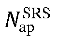
  42. The method according to claim 32, further comprising one or more of the following:
    determining that there is a corresponding relationship between the number of the antenna ports and the antenna port groups;
    determining that there is a corresponding relationship between the sequence generation parameter and the antenna port groups; or
    determining that there is a corresponding relationship between the number of the groups and the antenna port groups.
  43. The method according to claim 32, wherein before the receiving an SRS corresponding to the configuration information and a transmission rule, the method further comprises:
    determining the SRS sequence which is corresponding to an antenna port with an index of i;
    wherein in a case where a maximum number of cyclic shifts corresponding to the SRS resource is n SRS cs ,max = 8
    Figure imgb3890
    , a cyclic shift offset value n SRS cs , i
    Figure imgb3891
    corresponding to the SRS sequence which is corresponding to the antenna port with the index of i among the N ap SRS
    Figure imgb3892
    antenna ports is determined based on one or more of:
    Figure imgb3893
    n SRS cs + p i 1000 ;
    Figure imgb3894
    n SRS cs + i ;
    Figure imgb3895
    Figure imgb3896
    4 p i 1000 ;
    Figure imgb3897
    4i; 2 n SRS cs ,max N ap SRS p i 1000 ;
    Figure imgb3898
    2 p i 1000 ;
    Figure imgb3899
    2i;
    where pi is a port index of the antenna port with the index of i, and i is an integer less than or equal to N ap SRS 1
    Figure imgb3900
    .
  44. The method according to claim 43, wherein in a case where the maximum number of cyclic shifts corresponding to the SRS resource is n SRS cs ,max = 8
    Figure imgb3901
    , the cyclic shift offset value n SRS cs , i
    Figure imgb3902
    corresponding to the SRS sequence which is corresponding to the antenna port with the index of i among the N ap SRS
    Figure imgb3903
    antenna ports is determined based on one or more of:
    Figure imgb3904
    n SRS cs , i = n SRS cs + p i 1000 mod n SRS cs ,max ;
    Figure imgb3905
    n SRS cs , i = n SRS cs + i mod n SRS cs ,max ;
    Figure imgb3906
    Figure imgb3907
    n SRS cs , i = n SRS cs + 4 i mod n SRS cs ,max ;
    Figure imgb3908
    Figure imgb3909
    n SRS cs , i = n SRS cs + 2 i mod n SRS cs ,max ;
    Figure imgb3910
    where n SRS cs
    Figure imgb3911
    is a cyclic shift configuration value.
  45. The method according to claim 32, wherein before the receiving an SRS corresponding to the configuration information and a transmission rule, the method further comprises:
    determining the SRS sequence which is corresponding to an antenna port with an index of i;
    wherein in a case where a maximum number of cyclic shifts corresponding to the SRS resource is n SRS cs ,max = 12
    Figure imgb3912
    , a cyclic shift offset value n SRS cs , i
    Figure imgb3913
    corresponding to the SRS sequence which is corresponding to the antenna port with the index of i among the N ap SRS
    Figure imgb3914
    antenna ports is determined based on one or more of: n SRS cs ,max N ap SRS p i 1000 ;
    Figure imgb3915
    n SRS cs ,max p i 1000 N ap SRS ;
    Figure imgb3916
    n SRS cs + p i 1000 ;
    Figure imgb3917
    n SRS cs + i ;
    Figure imgb3918
    Figure imgb3919
    3 p i 1000 ;
    Figure imgb3920
    3i; 2 n SRS cs ,max N ap SRS p i 1000 ;
    Figure imgb3921
    2 p i 1000 ;
    Figure imgb3922
    2i; 4 n SRS cs ,max N ap SRS p i 1000 ;
    Figure imgb3923
    4 p i 1000 ;
    Figure imgb3924
    4i;
    Figure imgb3925
    6 p i 1000 ;
    Figure imgb3926
    6i;
    where pi is a port index of the antenna port with the index of i, and i is an integer less than or equal to N ap SRS 1
    Figure imgb3927
    .
  46. The method according to claim 45, wherein in a case where the maximum number of cyclic shifts corresponding to the SRS resource is n SRS cs ,max = 12
    Figure imgb3928
    , the cyclic shift offset value n SRS cs , i
    Figure imgb3929
    corresponding to the SRS sequence which is corresponding to the antenna port with the index of i among the N ap SRS
    Figure imgb3930
    antenna ports is determined based on one or more of:
    Figure imgb3931
    n SRS cs , i = n SRS cs + p i 1000 mod n SRS cs ,max ;
    Figure imgb3932
    n SRS cs , i = n SRS cs + i mod n SRS cs ,max ;
    Figure imgb3933
    Figure imgb3934
    n SRS cs , i = n SRS cs + 3 p i 1000 mod n SRS cs ,max ;
    Figure imgb3935
    Figure imgb3936
    n SRS cs , i = n SRS cs + 2 i mod n SRS cs ,max ;
    Figure imgb3937
    n SRS cs , i = n SRS cs + 4 n SRS cs ,max N ap SRS p i 1000 mod n SRS cs ,max ;
    Figure imgb3938
    n SRS cs , i = n SRS cs + 4 p i 1000 mod n SRS cs ,max ;
    Figure imgb3939
    n SRS cs , i = n SRS cs + 4 i mod n SRS cs ,max ;
    Figure imgb3940
    Figure imgb3941
    n SRS cs , i = n SRS cs + 6 p i 1000 mod n SRS cs ,max ;
    Figure imgb3942
    n SRS cs , i = n SRS cs + 6 i mod n SRS cs ,max ;
    Figure imgb3943
    where n SRS cs
    Figure imgb3944
    is a cyclic shift configuration value.
  47. The method according to claim 32, wherein before the receiving an SRS corresponding to the configuration information and a transmission rule, the method further comprises:
    determining the SRS sequence which is corresponding to an antenna port with an index of i;
    wherein in a case where a maximum number of cyclic shifts corresponding to the SRS resource is n SRS cs ,max = 6
    Figure imgb3945
    , a cyclic shift offset value n SRS cs , i
    Figure imgb3946
    corresponding to the SRS sequence which is corresponding to the antenna port with the index of i among the N ap SRS
    Figure imgb3947
    antenna ports is determined based on one or more of:
    Figure imgb3948
    2 p i 1000 ;
    Figure imgb3949
    2i; n SRS cs ,max N ap SRS p i 1000 ;
    Figure imgb3950
    n SRS cs + p i 1000 ;
    Figure imgb3951
    n SRS cs + i ;
    Figure imgb3952
    4 n SRS cs ,max N ap SRS p i 1000 ;
    Figure imgb3953
    4 p i 1000 ;
    Figure imgb3954
    4i; 3 n SRS cs ,max N ap SRS p i 1000 ;
    Figure imgb3955
    3 p i 1000 ;
    Figure imgb3956
    3i;
    where pi is a port index of the antenna port with the index of i, and i is an integer less than or equal to N ap SRS 1
    Figure imgb3957
    .
  48. The method according to claim 47, wherein in a case where the maximum number of cyclic shifts corresponding to the SRS resource is n SRS cs ,max = 6
    Figure imgb3958
    , the cyclic shift offset value n SRS cs , i
    Figure imgb3959
    corresponding to the SRS sequence which is corresponding to the antenna port with the index of i among the N ap SRS
    Figure imgb3960
    antenna ports is determined based on one or more of:
    Figure imgb3961
    n SRS cs , i = n SRS cs + 2 i mod n SRS cs ,max ;
    Figure imgb3962
    n SRS cs , i = n SRS cs + n SRS cs ,max N ap SRS p i 1000 mod n SRS cs ,max ;
    Figure imgb3963
    n SRS cs , i = n SRS cs + p i 1000 mod n SRS cs ,max ;
    Figure imgb3964
    n SRS cs , i = n SRS cs + i mod n SRS cs ,max ;
    Figure imgb3965
    n SRS cs , i = n SRS cs + 4 n SRS cs ,max N ap SRS p i 1000 mod n SRS cs ,max ;
    Figure imgb3966
    n SRS cs , i = n SRS cs + 4 p i 1000 mod n SRS cs ,max ;
    Figure imgb3967
    n SRS cs , i = n SRS cs + 4 i mod n SRS cs ,max ;
    Figure imgb3968
    n SRS cs , i = n SRS cs + 3 n SRS cs ,max N ap SRS p i 1000 mod n SRS cs ,max ;
    Figure imgb3969
    n SRS cs , i = n SRS cs + 3 p i 1000 mod n SRS cs ,max ;
    Figure imgb3970
    n SRS cs , i = n SRS cs + 3 i mod n SRS cs ,max ;
    Figure imgb3971
    where n SRS cs
    Figure imgb3972
    is a cyclic shift configuration value.
  49. The method according to claim 32, wherein before the receiving an SRS corresponding to the configuration information and a transmission rule, the method further comprises:
    determining the SRS sequence which is corresponding to an antenna port with an index of i;
    wherein in a case where a maximum number of cyclic shifts corresponding to the SRS resource is n SRS cs ,max = 16
    Figure imgb3973
    , a cyclic shift offset value n SRS cs , i
    Figure imgb3974
    corresponding to the SRS sequence which is corresponding to the antenna port with the index of i among the N ap SRS
    Figure imgb3975
    antenna ports is determined based on one or more of: 4 p i 1000 ;
    Figure imgb3976
    4i; 2 n SRS cs ,max N ap SRS p i 1000 ;
    Figure imgb3977
    2 p i 1000 ;
    Figure imgb3978
    2i;
    Figure imgb3979
    n SRS cs + p i 1000 ;
    Figure imgb3980
    n SRS cs + i ;
    Figure imgb3981
    Figure imgb3982
    3 p i 1000 ;
    Figure imgb3983
    3i; 4 n SRS cs ,max N ap SRS p i 1000 ;
    Figure imgb3984
    where pi is a port index of the antenna port with the index of i, and i is an integer less than or equal to N ap SRS 1
    Figure imgb3985
    .
  50. The method according to claim 49, wherein in a case where the maximum number of cyclic shifts corresponding to the SRS resource is n SRS cs ,max = 16
    Figure imgb3986
    , the cyclic shift offset value n SRS cs , i
    Figure imgb3987
    corresponding to the SRS sequence which is corresponding to the antenna port with the index of i among the N ap SRS
    Figure imgb3988
    antenna ports is determined based on one or more of: n SRS cs , i = n SRS cs + 4 p i 1000 mod n SRS cs ,max ;
    Figure imgb3989
    Figure imgb3990
    n SRS cs , i = n SRS cs + 2 i mod n SRS cs ,max ;
    Figure imgb3991
    Figure imgb3992
    n SRS cs , i = n SRS cs + p i 1000 mod n SRS cs ,max ;
    Figure imgb3993
    n SRS cs , i = n SRS cs + i mod n SRS cs ,max ;
    Figure imgb3994
    Figure imgb3995
    n SRS cs , i = n SRS cs + 3 p i 1000 mod n SRS cs ,max ;
    Figure imgb3996
    n SRS cs , i = n SRS cs + 3 i mod n SRS cs ,max ;
    Figure imgb3997
    n SRS cs , i = n SRS cs + 4 n SRS cs ,max N ap SRS p i 1000 mod n SRS cs ,max ;
    Figure imgb3998
    where n SRS cs
    Figure imgb3999
    is a cyclic shift configuration value.
  51. The method according to claim 32, wherein before the receiving an SRS corresponding to the configuration information and a transmission rule, the method further comprises:
    determining the SRS sequence which is corresponding to an antenna port with an index of i;
    wherein a cyclic shift offset value n SRS cs , i
    Figure imgb4000
    corresponding to the SRS sequence which is corresponding to the antenna port with the index of i among the N ap SRS
    Figure imgb4001
    antenna ports is determined based on one or more of: n SRS cs ,max N ap SRS p i 1000 ;
    Figure imgb4002
    n SRS cs + p i 1000 ;
    Figure imgb4003
    n SRS cs + i ;
    Figure imgb4004
    3 n SRS cs ,max N ap SRS p i 1000 ;
    Figure imgb4005
    3 p i 1000 ;
    Figure imgb4006
    3i; 2 n SRS cs ,max N ap SRS p i 1000 ;
    Figure imgb4007
    2 p i 1000 ;
    Figure imgb4008
    2i; 4 n SRS cs ,max N ap SRS p i 1000 ;
    Figure imgb4009
    4 p i 1000 ;
    Figure imgb4010
    4i;
    Figure imgb4011
    6 p i 1000 ;
    Figure imgb4012
    6i;
    where pi is a port index of the antenna port with the index of i, and i is an integer less than or equal to N ap SRS 1
    Figure imgb4013
    .
  52. The method according to claim 51, wherein the cyclic shift offset value n SRS cs , i
    Figure imgb4014
    corresponding to the SRS sequence which is corresponding to the antenna port with the index of i among the N ap SRS
    Figure imgb4015
    antenna ports is determined based on one or more of: n SRS cs , i = n SRS cs + n SRS cs ,max N ap SRS p i 1000 mod n SRS cs ,max ;
    Figure imgb4016
    n SRS cs , i = n SRS cs + p i 1000 mod n SRS cs ,max ;
    Figure imgb4017
    n SRS cs , i = n SRS cs + i mod n SRS cs ,max ;
    Figure imgb4018
    n SRS cs , i = n SRS cs + 3 n SRS cs ,max N ap SRS p i 1000 mod n SRS cs ,max ;
    Figure imgb4019
    n SRS cs , i = n SRS cs + 3 p i 1000 mod n SRS cs ,max ;
    Figure imgb4020
    n SRS cs , i = n SRS cs + 3 i mod n SRS cs ,max ;
    Figure imgb4021
    n SRS cs , i = n SRS cs + 2 n SRS cs ,max N ap SRS p i 1000 mod n SRS cs ,max ;
    Figure imgb4022
    n SRS cs , i = n SRS cs + 2 p i 1000 mod n SRS cs ,max ;
    Figure imgb4023
    n SRS cs , i = n SRS cs + 2 i mod n SRS cs ,max ;
    Figure imgb4024
    n SRS cs , i = n SRS cs + 4 n SRS cs ,max N ap SRS p i 1000 mod n SRS cs ,max ;
    Figure imgb4025
    n SRS cs , i = n SRS cs + 4 p i 1000 mod n SRS cs ,max ;
    Figure imgb4026
    n SRS cs , i = n SRS cs + 4 i mod n SRS cs ,max ;
    Figure imgb4027
    Figure imgb4028
    n SRS cs , i = n SRS cs + 6 p i 1000 mod n SRS cs ,max ;
    Figure imgb4029
    n SRS cs , i = n SRS cs + 6 i mod n SRS cs ,max ;
    Figure imgb4030
    where n SRS cs
    Figure imgb4031
    is a cyclic shift configuration value.
  53. The method according to any one of claims 43 to 52, wherein the antenna ports in different antenna port groups adopt different formulas to determine the cyclic shift offset value.
  54. The method according to claim 32, wherein the receiving an SRS corresponding to the configuration information and a transmission rule comprises:
    receiving the SRS sequence which is corresponding to an antenna port with an index of i, from a starting position of a frequency domain resource which is corresponding to a position parameter k TC p i
    Figure imgb4032
    of the frequency domain resource;
    wherein in a case where n SRS cs ,max = 8
    Figure imgb4033
    or 16, the position parameter k TC p i
    Figure imgb4034
    of the frequency domain resource corresponding to the antenna port with the index of i among the N ap SRS
    Figure imgb4035
    antenna ports is determined based on one or more of: k ¯ TC ;
    Figure imgb4036
    k ¯ TC + 3 ;
    Figure imgb4037
    k ¯ TC + 2 ;
    Figure imgb4038
    k ¯ TC + 1 ;
    Figure imgb4039
    k ¯ TC + 3 K TC / 4 ;
    Figure imgb4040
    k ¯ TC + 2 K TC / 4 ;
    Figure imgb4041
    k ¯ TC + K TC / 4 ;
    Figure imgb4042
    k ¯ TC + 4 ;
    Figure imgb4043
    where k TC is an offset of a comb in the frequency domain; and K TC is a transmission comb number.
  55. The method according to claim 54, wherein in a case where n SRS cs ,max = 8
    Figure imgb4044
    or 16, the position parameter k TC p i
    Figure imgb4045
    of the frequency domain resource corresponding to the antenna port with the index of i among the N ap SRS
    Figure imgb4046
    antenna ports is determined based on one or more of: k TC p i = k ¯ TC ;
    Figure imgb4047
    k TC p i = k ¯ TC + 3 mod K TC ;
    Figure imgb4048
    k TC p i = k ¯ TC + 2 mod K TC ;
    Figure imgb4049
    k TC p i = k ¯ TC + 1 mod K TC ;
    Figure imgb4050
    k TC p i = k ¯ TC + 3 K TC / 4 mod K TC ;
    Figure imgb4051
    k TC p i = k ¯ TC + 2 K TC / 4 mod K TC ;
    Figure imgb4052
    k TC p i = k ¯ TC + K TC / 4 mod K TC ;
    Figure imgb4053
    k TC p i = k ¯ TC + 4 mod K TC .
    Figure imgb4054
  56. The method according to claim 32, wherein the receiving an SRS corresponding to the configuration information and a transmission rule comprises:
    receiving the SRS sequence which is corresponding to an antenna port with an index of i, from a starting position of a frequency domain resource which is corresponding to a position parameter k TC p i
    Figure imgb4055
    of the frequency domain resource;
    wherein in a case where n SRS cs ,max = 12
    Figure imgb4056
    or 6, the position parameter k TC p i
    Figure imgb4057
    of the frequency domain resource corresponding to the antenna port with the index of i among the N ap SRS
    Figure imgb4058
    antenna ports is determined based on one or more of: k ¯ TC ;
    Figure imgb4059
    k ¯ TC + 3 ;
    Figure imgb4060
    k ¯ TC + 2 ;
    Figure imgb4061
    k ¯ TC + 1 ;
    Figure imgb4062
    k ¯ TC + 3 K TC / 4 ;
    Figure imgb4063
    k ¯ TC + 2 K TC / 4 ;
    Figure imgb4064
    k ¯ TC + K TC / 4 ;
    Figure imgb4065
    where k TC is an offset of a comb in the frequency domain; and K TC is a transmission comb number.
  57. The method according to claim 56, wherein in a case where n SRS cs ,max = 12
    Figure imgb4066
    or 16, the position parameter k TC p i
    Figure imgb4067
    of the frequency domain resource corresponding to the antenna port with the index of i among the N ap SRS
    Figure imgb4068
    antenna ports is determined based on one or more of: k TC p i = k ¯ TC ;
    Figure imgb4069
    k TC p i = k ¯ TC + 3 mod K TC ;
    Figure imgb4070
    k TC p i = k ¯ TC + 2 mod K TC ;
    Figure imgb4071
    k TC p i = k ¯ TC + 1 mod K TC ;
    Figure imgb4072
    k TC p i = k ¯ TC + 3 K TC / 4 mod K TC ;
    Figure imgb4073
    k TC p i = k ¯ TC + 2 K TC / 4 mod K TC ;
    Figure imgb4074
    k TC p i = k ¯ TC + K TC / 4 mod K TC .
    Figure imgb4075
  58. The method according to claim 32, wherein the receiving an SRS corresponding to the configuration information and a transmission rule comprises:
    receiving the SRS sequence which is corresponding to an antenna port with an index of i, from a starting position of a frequency domain resource which is corresponding to a position parameter k TC p i
    Figure imgb4076
    of the frequency domain resource;
    wherein the position parameter k TC p i
    Figure imgb4077
    of the frequency domain resource corresponding to the antenna port with the index of i among the N ap SRS
    Figure imgb4078
    antenna ports is determined based on one or more of: k ¯ TC + 3 ;
    Figure imgb4079
    k ¯ TC + 2 ;
    Figure imgb4080
    k ¯ TC + 1 ;
    Figure imgb4081
    k ¯ TC + 3 K TC / 4 ;
    Figure imgb4082
    k ¯ TC + K TC / 4 ;
    Figure imgb4083
    k ¯ TC + 4 ;
    Figure imgb4084
    where k TC is an offset of a comb in the frequency domain; and K TC is a transmission comb number.
  59. The method according to claim 58, wherein the position parameter k TC p i
    Figure imgb4085
    of the frequency domain resource corresponding to the antenna port with the index of i among the N ap SRS
    Figure imgb4086
    antenna ports is determined based on one or more of: k TC p i = k ¯ TC + 3 mod K TC ;
    Figure imgb4087
    k TC p i = k ¯ TC + 2 mod K TC ;
    Figure imgb4088
    k TC p i = k ¯ TC + 1 mod K TC ;
    Figure imgb4089
    k TC p i = k ¯ TC + 3 K TC / 4 mod K TC ;
    Figure imgb4090
    k TC p i = k ¯ TC + K TC / 4 mod K TC ;
    Figure imgb4091
    k TC p i = k ¯ TC + 4 mod K TC .
    Figure imgb4092
  60. The method according to any one of claims 54 to 59, wherein the antenna ports in different antenna port groups adopt different formulas to determine the cyclic shift offset value.
  61. The method according to any one of claims 32 to 60, wherein the N ap SRS
    Figure imgb4093
    is valued as 8.
  62. A terminal device, comprising a memory, a transceiver and a processor:
    the memory is configured to store a computer program; the transceiver is configured to transceive data under the control of the processor; and the processor is configured to read the computer program in the memory and perform processes of:
    receiving configuration information of a Sounding Reference Signal (SRS) resource by the transceiver;
    transmitting an SRS corresponding to the SRS resource by the transceiver according to the configuration information and a transmission rule;
    wherein the SRS resource comprises N ap SRS
    Figure imgb4094
    antenna ports, and the transmission rule comprises one or more of the following:
    cyclic shift offset values corresponding to SRS sequences which are corresponding to all or part of the antenna ports in the N ap SRS
    Figure imgb4095
    antenna ports are continuous;
    the N ap SRS
    Figure imgb4096
    antenna ports are mapped to at least two groups of time domain resources and/or frequency domain resources; or
    the N ap SRS
    Figure imgb4097
    is an integer greater than 4.
  63. The terminal device according to claim 62, wherein the N ap SRS
    Figure imgb4098
    antenna ports comprise a plurality of antenna port groups each corresponding to one group of time domain resources and/or frequency domain resources.
  64. The terminal device according to claim 63, wherein the processor reads the computer program in the memory and performs one of operations of:
    obtaining first information;
    wherein the first information comprises one or more of:
    grouping information of the antenna ports;
    a sequence generation parameter of the SRS; or
    resource mapping mode information.
  65. The terminal device according to claim 63 or 64, wherein the grouping of the N ap SRS
    Figure imgb4099
    antenna ports satisfies one or more of the following:
    indexes of the antenna ports comprised in each of the antenna port groups are continuous; or
    indexes of the antenna ports comprised in each of the antenna port groups are at an interval of a preset value.
  66. The terminal device according to 63 or 64, wherein the cyclic shift offset values corresponding to the SRS sequences which are corresponding to the antenna ports comprised in different antenna port groups among the plurality of antenna port groups are the same.
  67. The terminal device according to 63 or 64, wherein the grouping of the N ap SRS
    Figure imgb4100
    antenna ports satisfies one of the following:
    the N ap SRS
    Figure imgb4101
    antenna ports are in one group;
    the N ap SRS
    Figure imgb4102
    antenna ports are grouped equally; or
    the N ap SRS
    Figure imgb4103
    antenna ports are grouped unequally.
  68. The terminal device according to claim 64, wherein the configuration information comprises information indicative of the first information.
  69. The terminal device according to claim 64, wherein the sequence generation parameter of the SRS comprises one or more of a maximum number of cyclic shifts and a cyclic shift configuration.
  70. The terminal device according to claim 64, wherein the resource mapping mode information comprises one of the following:
    the antenna ports are mapped to one time domain resource group and/or one frequency domain resource group;
    the antenna ports are mapped to a plurality of time domain resource groups and/or a plurality of frequency domain resource groups; or
    an index of the resource mapping mode.
  71. The terminal device according to claim 64, wherein the processor reads the computer program in the memory and performs an operation of:
    according to the first information, determining one or more of a grouping of the N ap SRS
    Figure imgb4104
    antenna ports, the SRS sequence corresponding to each of the N ap SRS
    Figure imgb4105
    antenna ports, and the time domain resource and/or the frequency domain resource to which each of the N ap SRS
    Figure imgb4106
    antenna ports is mapped.
  72. The terminal device according to any one of claims 63 to 71, wherein the grouping information of the N ap SRS
    Figure imgb4107
    antenna ports comprises the number of the groups, which comprises one or more of:
    the number of the antenna port groups;
    the number of the time domain resource groups to which the SRS sequences are mapped; or
    the number of the frequency domain resource groups to which the SRS sequences are mapped.
  73. The terminal device according to claim 62, wherein the processor reads the computer program in the memory and performs an operation of:
    according to a corresponding relationship, determining one or more of a grouping of the N ap SRS
    Figure imgb4108
    antenna ports, the SRS sequence corresponding to each of the N ap SRS
    Figure imgb4109
    antenna ports, and the time domain resource and/or the frequency domain resource to which each of the N ap SRS
    Figure imgb4110
    antenna ports is mapped;
    wherein the corresponding relationship comprises one or more of:
    a corresponding relationship between the number of the antenna ports and the antenna port groups;
    a corresponding relationship between the sequence generation parameter and the antenna port groups; or
    a corresponding relationship between the number of the groups and the antenna port groups.
  74. The terminal device according to claim 62, wherein the processor reads the computer program in the memory and performs operations of:
    in a case where a maximum number of cyclic shifts corresponding to the SRS resource is n SRS cs ,max = 8
    Figure imgb4111
    , determining a cyclic shift offset value n SRS cs , i
    Figure imgb4112
    corresponding to the SRS sequence which is corresponding to an antenna port with an index of i among the N ap SRS
    Figure imgb4113
    antenna ports based on one or more of:
    Figure imgb4114
    n SRS cs + p i 1000 ;
    Figure imgb4115
    n SRS cs + i ;
    Figure imgb4116
    Figure imgb4117
    4 n SRS cs ,max N ap SRS p i 1000 ;
    Figure imgb4118
    4 p i 1000 ;
    Figure imgb4119
    4i; 2 n SRS cs ,max N ap SRS p i 1000 ;
    Figure imgb4120
    2 p i 1000 ;
    Figure imgb4121
    2i;
    determining the SRS sequence which is corresponding to the antenna port with the index of i according to the cyclic shift offset value;
    where pi is a port index of the antenna port with the index of i, and i is an integer less than or equal to N ap SRS 1
    Figure imgb4122
    .
  75. The terminal device according to claim 74, wherein in a case where the maximum number of cyclic shifts corresponding to the SRS resource is n SRS cs ,max = 8
    Figure imgb4123
    , the cyclic shift offset value n SRS cs , i
    Figure imgb4124
    corresponding to the SRS sequence which is corresponding to the antenna port with the index of i among the N ap SRS
    Figure imgb4125
    antenna ports is determined based on one or more of:
    Figure imgb4126
    Figure imgb4127
    Figure imgb4128
    n SRS cs ,i = n SRS cs + 4 p i 1000 mod n SRS cs ,max ;
    Figure imgb4129
    n SRS cs ,i = n SRS cs + 4 i mod n SRS cs ,max ;
    Figure imgb4130
    n SRS cs ,i = n SRS cs + 2 n SRS cs ,max N ap SRS p i 1000 mod n SRS cs ,max ;
    Figure imgb4131
    n SRS cs ,i = n SRS cs + 2 p i 1000 mod n SRS cs ,max ;
    Figure imgb4132
    n SRS cs ,i = n SRS cs + 2 i mod n SRS cs ,max ;
    Figure imgb4133
    where n SRS cs
    Figure imgb4134
    is a cyclic shift configuration value.
  76. The terminal device according to claim 62, wherein the processor reads the computer program in the memory and performs operations of:
    in a case where a maximum number of cyclic shifts corresponding to the SRS resource is n SRS cs ,max = 12
    Figure imgb4135
    , determining a cyclic shift offset value n SRS cs , i
    Figure imgb4136
    corresponding to the SRS sequence which is corresponding to an antenna port with an index of i among the N ap SRS
    Figure imgb4137
    antenna ports based on one or more of:
    Figure imgb4138
    n SRS cs + p i 1000;
    Figure imgb4139
    n SRS cs + i;
    Figure imgb4140
    Figure imgb4141
    3 p i 1000 ;
    Figure imgb4142
    3i; 2 n SRS cs ,max N ap SRS p i 1000 ;
    Figure imgb4143
    2 p i 1000 ;
    Figure imgb4144
    2i; 4 n SRS cs ,max N ap SRS p i 1000 ;
    Figure imgb4145
    4 p i 1000 ;
    Figure imgb4146
    4i;
    Figure imgb4147
    6 p i 1000 ;
    Figure imgb4148
    6i;
    determining the SRS sequence which is corresponding to the antenna port with the index of i according to the cyclic shift offset value;
    where pi is a port index of the antenna port with the index of i, and i is an integer less than or equal to N ap SRS 1
    Figure imgb4149
    .
  77. The terminal device according to claim 76, wherein in a case where the maximum number of cyclic shifts corresponding to the SRS resource is n SRS cs ,max = 12
    Figure imgb4150
    , the cyclic shift offset value n SRS cs , i
    Figure imgb4151
    corresponding to the SRS sequence which is corresponding to the antenna port with the index of i among the N ap SRS
    Figure imgb4152
    antenna ports is determined based on one or more of:
    Figure imgb4153
    n SRS cs ,i = n SRS cs + p i 1000 mod n SRS cs ,max ;
    Figure imgb4154
    n SRS cs ,i = n SRS cs + i mod n SRS cs ,max ;
    Figure imgb4155
    Figure imgb4156
    n SRS cs ,i = n SRS cs + 3 p i 1000 mod n SRS cs ,max ;
    Figure imgb4157
    n SRS cs ,i = n SRS cs + 3 i mod n SRS cs ,max ;
    Figure imgb4158
    n SRS cs ,i = n SRS cs + 2 n SRS cs ,max N ap SRS p i 1000 mod n SRS cs ,max ;
    Figure imgb4159
    n SRS cs ,i = n SRS cs + 2 p i 1000 mod n SRS cs ,max ;
    Figure imgb4160
    n SRS cs ,i = n SRS cs + 2 i mod n SRS cs ,max ;
    Figure imgb4161
    n SRS cs ,i = n SRS cs + 4 n SRS cs ,max N ap SRS p i 1000 mod n SRS cs ,max ;
    Figure imgb4162
    n SRS cs ,i = n SRS cs + 4 p i 1000 mod n SRS cs ,max ;
    Figure imgb4163
    n SRS cs ,i = n SRS cs + 4 i mod n SRS cs ,max ;
    Figure imgb4164
    Figure imgb4165
    n SRS cs ,i = n SRS cs + 6 p i 1000 mod n SRS cs ,max ;
    Figure imgb4166
    n SRS cs ,i = n SRS cs + 6 i mod n SRS cs ,max ;
    Figure imgb4167
    where n SRS cs
    Figure imgb4168
    is a cyclic shift configuration value.
  78. The terminal device according to claim 62, wherein the processor reads the computer program in the memory and performs operations of:
    in a case where a maximum number of cyclic shifts corresponding to the SRS resource is n SRS cs ,max = 6
    Figure imgb4169
    , determining a cyclic shift offset value n SRS cs , i
    Figure imgb4170
    corresponding to the SRS sequence which is corresponding to an antenna port with an index of i among the N ap SRS
    Figure imgb4171
    antenna ports based on one or more of:
    Figure imgb4172
    2 p i 1000 ;
    Figure imgb4173
    2i; n SRS cs ,max N ap SRS p i 1000 ;
    Figure imgb4174
    n SRS cs + p i 1000 ;
    Figure imgb4175
    n SRS cs + i ;
    Figure imgb4176
    4 n SRS cs ,max N ap SRS p i 1000 ;
    Figure imgb4177
    4 p i 1000 ;
    Figure imgb4178
    4i; 3 n SRS cs ,max N ap SRS p i 1000 ;
    Figure imgb4179
    3 p i 1000 ;
    Figure imgb4180
    3i;
    determining the SRS sequence which is corresponding to the antenna port with the index of i according to the cyclic shift offset value;
    where pi is a port index of the antenna port with the index of i, and i is an integer less than or equal to N ap SRS 1
    Figure imgb4181
    .
  79. The terminal device according to claim 78, wherein in a case where the maximum number of cyclic shifts corresponding to the SRS resource is n SRS cs ,max = 6
    Figure imgb4182
    , the cyclic shift offset value n SRS cs , i
    Figure imgb4183
    corresponding to the SRS sequence which is corresponding to the antenna port with the index of i among the N ap SRS
    Figure imgb4184
    antenna ports is determined based on one or more of:
    Figure imgb4185
    n SRS cs ,i = n SRS cs + 2 p i 1000 mod n SRS cs ,max ;
    Figure imgb4186
    n SRS cs ,i = n SRS cs + 2i mod n SRS cs ,max ;
    Figure imgb4187
    n SRS cs ,i = n SRS cs + n SRS cs ,max N ap SRS p i 1000 mod n SRS cs ,max ;
    Figure imgb4188
    n SRS cs ,i = n SRS cs + p i 1000 mod n SRS cs ,max ;
    Figure imgb4189
    n SRS cs ,i = n SRS cs + 1 mod n SRS cs ,max ;
    Figure imgb4190
    n SRS cs ,i = n SRS cs + 4 n SRS cs ,max N ap SRS p i 1000 mod n SRS cs ,max ;
    Figure imgb4191
    n SRS cs ,i = n SRS cs + 4 p i 1000 mod n SRS cs ,max ;
    Figure imgb4192
    n SRS cs ,i = n SRS cs + 4i mod n SRS cs ,max ;
    Figure imgb4193
    n SRS cs ,i = n SRS cs + 3 n SRS cs ,max N ap SRS p i 1000 mod n SRS cs ,max ;
    Figure imgb4194
    n SRS cs ,i = n SRS cs + 3 p i 1000 mod n SRS cs ,max ;
    Figure imgb4195
    n SRS cs ,i = n SRS cs + 3 i mod n SRS cs ,max ;
    Figure imgb4196
    where n SRS cs
    Figure imgb4197
    is a cyclic shift configuration value.
  80. The terminal device according to claim 62, wherein the processor reads the computer program in the memory and performs operations of:
    in a case where a maximum number of cyclic shifts corresponding to the SRS resource is n SRS cs ,max = 16
    Figure imgb4198
    , determining a cyclic shift offset value n SRS cs , i
    Figure imgb4199
    corresponding to the SRS sequence which is corresponding to an antenna port with an index of i among the N ap SRS
    Figure imgb4200
    antenna ports based on one or more of: 4 p i 1000 ;
    Figure imgb4201
    4i; 2 n SRS cs ,max N ap SRS p i 1000 ;
    Figure imgb4202
    2 p i 1000 ;
    Figure imgb4203
    2i;
    Figure imgb4204
    n SRS cs + p i 1000 ;
    Figure imgb4205
    n SRS cs + i ;
    Figure imgb4206
    Figure imgb4207
    3 p i 1000 ;
    Figure imgb4208
    3i; 4 n SRS cs ,max N ap SRS p i 1000 ;
    Figure imgb4209
    determining the SRS sequence which is corresponding to the antenna port with the index of i according to the cyclic shift offset value;
    where pi is a port index of the antenna port with the index of i, and i is an integer less than or equal to N ap SRS 1
    Figure imgb4210
    .
  81. The terminal device according to claim 80, wherein in a case where the maximum number of cyclic shifts corresponding to the SRS resource is n SRS cs ,max = 16
    Figure imgb4211
    , the cyclic shift offset value n SRS cs , i
    Figure imgb4212
    corresponding to the SRS sequence which is corresponding to the antenna port with the index of i among the N ap SRS
    Figure imgb4213
    antenna ports is determined based on one or more of: n SRS cs ,i = n SRS cs + 4 p i 1000 mod n SRS cs ,max ;
    Figure imgb4214
    n SRS cs ,i = n SRS cs + 4 i mod n SRS cs ,max ;
    Figure imgb4215
    n SRS cs ,i = n SRS cs + 2 n SRS cs ,max N ap SRS p i 1000 mod n SRS cs ,max ;
    Figure imgb4216
    n SRS cs ,i = n SRS cs + 2 p i 1000 mod n SRS cs ,max ;
    Figure imgb4217
    n SRS cs ,i = n SRS cs + 2 i mod n SRS cs ,max ;
    Figure imgb4218
    Figure imgb4219
    n SRS cs ,i = n SRS cs + p i 1000 mod n SRS cs ,max ;
    Figure imgb4220
    n SRS cs ,i = n SRS cs + i mod n SRS cs ,max ;
    Figure imgb4221
    Figure imgb4222
    n SRS cs ,i = n SRS cs + 3 p i 1000 mod n SRS cs ,max ;
    Figure imgb4223
    n SRS cs ,i = n SRS cs + 3 i mod n SRS cs ,max ;
    Figure imgb4224
    n SRS cs ,i = n SRS cs + 4 n SRS cs ,max N ap SRS p i 1000 mod n SRS cs ,max ;
    Figure imgb4225
    where n SRS cs
    Figure imgb4226
    is a cyclic shift configuration value.
  82. The terminal device according to claim 62, wherein the processor reads the computer program in the memory and performs operations of:
    determining a cyclic shift offset value n SRS cs , i
    Figure imgb4227
    corresponding to the SRS sequence which is corresponding to an antenna port with an index of i among the N ap SRS
    Figure imgb4228
    antenna ports based on one or more of: n SRS cs ,max N ap SRS p i 1000 ;
    Figure imgb4229
    n SRS cs + p i 1000 ;
    Figure imgb4230
    n SRS cs + i ;
    Figure imgb4231
    3 n SRS cs ,max N ap SRS p i 1000 ;
    Figure imgb4232
    3 p i 1000 ;
    Figure imgb4233
    3i; 2 n SRS cs ,max N ap SRS p i 1000 ;
    Figure imgb4234
    2 p i 1000 ;
    Figure imgb4235
    2i; 4 n SRS cs ,max N ap SRS p i 1000 ;
    Figure imgb4236
    4 p i 1000 ;
    Figure imgb4237
    4i; n SRS cs ,max p i 1000 / 4 N ap SRS / 4 ; 6 n SRS cs ,max N ap SRS p i 1000 ;
    Figure imgb4238
    6 p i 1000 ;
    Figure imgb4239
    6i;
    determining the SRS sequence which is corresponding to the antenna port with the index of i according to the cyclic shift offset value;
    where pi is a port index of the antenna port with the index of i, and i is an integer less than or equal to N ap SRS 1
    Figure imgb4240
    .
  83. The terminal device according to claim 82, wherein the cyclic shift offset value n SRS cs , i
    Figure imgb4241
    corresponding to the SRS sequence which is corresponding to the antenna port with the index of i among the N ap SRS
    Figure imgb4242
    antenna ports is determined based on one or more of: n SRS cs ,i = n SRS cs + n SRS cs ,max N ap SRS p i 1000 mod n SRS cs ,max ;
    Figure imgb4243
    n SRS cs ,i = n SRS cs + p i 1000 mod n SRS cs ,max ;
    Figure imgb4244
    n SRS cs ,i = n SRS cs + i mod n SRS cs ,max ;
    Figure imgb4245
    n SRS cs ,i = n SRS cs + 3 n SRS cs ,max N ap SRS p i 1000 mod n SRS cs ,max ;
    Figure imgb4246
    n SRS cs ,i = n SRS cs + 3 p i 1000 mod n SRS cs ,max ;
    Figure imgb4247
    n SRS cs ,i = n SRS cs + 3 i mod n SRS cs ,max ;
    Figure imgb4248
    n SRS cs ,i = n SRS cs + 2 n SRS cs ,max N ap SRS p i 1000 mod n SRS cs ,max ;
    Figure imgb4249
    n SRS cs ,i = n SRS cs + 2 p i 1000 mod n SRS cs ,max ;
    Figure imgb4250
    n SRS cs ,i = n SRS cs + 2 i mod n SRS cs ,max ;
    Figure imgb4251
    n SRS cs ,i = n SRS cs + 4 n SRS cs ,max N ap SRS p i 1000 mod n SRS cs ,max ;
    Figure imgb4252
    n SRS cs ,i = n SRS cs + 4 p i 1000 mod n SRS cs ,max ;
    Figure imgb4253
    n SRS cs ,i = n SRS cs + 4 i mod n SRS cs ,max ;
    Figure imgb4254
    Figure imgb4255
    n SRS cs ,i = n SRS cs + 6 p i 1000 mod n SRS cs ,max ;
    Figure imgb4256
    n SRS cs ,i = n SRS cs + 6 i mod n SRS cs ,max ;
    Figure imgb4257
    where n SRS cs
    Figure imgb4258
    is a cyclic shift configuration value.
  84. The terminal device according to any one of claims 74 to 83, wherein the antenna ports in different antenna port groups adopt different formulas to determine the cyclic shift offset value.
  85. The terminal device according to claim 62, wherein the processor reads the computer program in the memory and performs operations of:
    in a case where n SRS cs ,max = 8
    Figure imgb4259
    or 16, determining a position parameter k TC p i
    Figure imgb4260
    of a frequency domain resource corresponding to an antenna port with an index of i among the N ap SRS
    Figure imgb4261
    antenna ports based on one or more of: k ¯ TC ;
    Figure imgb4262
    k ¯ TC + 3 ;
    Figure imgb4263
    k ¯ TC + 2 ;
    Figure imgb4264
    k ¯ TC + 1 ;
    Figure imgb4265
    k ¯ TC + 3 K TC / 4 ;
    Figure imgb4266
    k ¯ TC + 2 K TC / 4 ;
    Figure imgb4267
    k ¯ TC + K TC / 4 ;
    Figure imgb4268
    k ¯ TC + 4 ;
    Figure imgb4269
    determining a starting position of a frequency domain resource to which the SRS sequence corresponding to the antenna port with the index of i is mapped, according to the position parameter k TC p i
    Figure imgb4270
    of the frequency domain resource; and
    transmitting the SRS sequence corresponding to the antenna port with the index of i from the starting position of the frequency domain resource;
    where k TC is an offset of a comb in the frequency domain; and K TC is a transmission comb number.
  86. The terminal device according to claim 85, wherein in a case where n SRS cs ,max = 8 or 16
    Figure imgb4271
    , the position parameter k TC p i
    Figure imgb4272
    of the frequency domain resource corresponding to an antenna port with an index of i among the N ap SRS
    Figure imgb4273
    antenna ports is determined based on one or more of: k TC p i = k ¯ TC ;
    Figure imgb4274
    k TC p i = k ¯ TC + 3 mod K TC ;
    Figure imgb4275
    k TC p i = k ¯ TC + 2 mod K TC ;
    Figure imgb4276
    k TC p i = k ¯ TC + 1 mod K TC ;
    Figure imgb4277
    k TC p i = k ¯ TC + 3 K TC / 4 mod K TC ;
    Figure imgb4278
    k TC p i = k ¯ TC + 2 K TC / 4 mod K TC ;
    Figure imgb4279
    k TC p i = k ¯ TC + K TC / 4 mod K TC ;
    Figure imgb4280
    k TC p i = k ¯ TC + 4 mod K TC .
    Figure imgb4281
  87. The terminal device according to claim 62, wherein the processor reads the computer program in the memory and performs operations of:
    in a case where n SRS cs ,max = 12 or 6
    Figure imgb4282
    , determining a position parameter k TC p i
    Figure imgb4283
    of a frequency domain resource corresponding to an antenna port with an index of i among the N ap SRS
    Figure imgb4284
    antenna ports based on one or more of: k ¯ TC ;
    Figure imgb4285
    k ¯ TC + 3 ;
    Figure imgb4286
    k ¯ TC + 2 ;
    Figure imgb4287
    k ¯ TC + 1 ;
    Figure imgb4288
    k ¯ TC + 3 K TC / 4 ;
    Figure imgb4289
    k ¯ TC + 2 K TC / 4 ;
    Figure imgb4290
    k ¯ TC + K TC / 4 ;
    Figure imgb4291
    determining a starting position of a frequency domain resource to which the SRS sequence corresponding to the antenna port with the index of i is mapped, according to the position parameter k TC p i
    Figure imgb4292
    of the frequency domain resource; and
    transmitting the SRS sequence corresponding to the antenna port with the index of i from the starting position of the frequency domain resource;
    where k TC is an offset of a comb in the frequency domain; and K TC is a transmission comb number.
  88. The terminal device according to claim 87, wherein in a case where n SRS cs ,max = 12 or 6
    Figure imgb4293
    , the position parameter k TC p i
    Figure imgb4294
    of the frequency domain resource corresponding to an antenna port with an index of i among the N ap SRS
    Figure imgb4295
    antenna ports is determined based on one or more of: k TC p i = k ¯ TC ;
    Figure imgb4296
    k TC p i = k ¯ TC + 3 mod K TC ;
    Figure imgb4297
    k TC p i = k ¯ TC + 2 mod K TC ;
    Figure imgb4298
    k TC p i = k ¯ TC + 1 mod K TC ;
    Figure imgb4299
    k TC p i = k ¯ TC + 3 K TC / 4 mod K TC ;
    Figure imgb4300
    k TC p i = k ¯ TC + 2 K TC / 4 mod K TC ;
    Figure imgb4301
    k TC p i = k ¯ TC + K TC / 4 mod K TC .
    Figure imgb4302
  89. The terminal device according to claim 62, wherein the processor reads the computer program in the memory and performs operations of:
    determining a position parameter k TC p i
    Figure imgb4303
    of a frequency domain resource corresponding to an antenna port with an index of i among the N ap SRS
    Figure imgb4304
    antenna ports based on one or more of: k ¯ TC + 3 ;
    Figure imgb4305
    k ¯ TC + 2 ;
    Figure imgb4306
    k ¯ TC + 1 ;
    Figure imgb4307
    k ¯ TC + 3 K TC / 4 ;
    Figure imgb4308
    k ¯ TC + K TC / 4 ;
    Figure imgb4309
    k ¯ TC + 4 ;
    Figure imgb4310
    determining a starting position of a frequency domain resource to which the SRS sequence corresponding to the antenna port with the index of i is mapped, according to the position parameter k TC p i
    Figure imgb4311
    of the frequency domain resource; and
    transmitting the SRS sequence corresponding to the antenna port with the index of i from the starting position of the frequency domain resource;
    where k TC is an offset of a comb in the frequency domain; and K TC is a transmission comb number.
  90. The terminal device according to claim 89, wherein the position parameter k TC p i
    Figure imgb4312
    of the frequency domain resource corresponding to the antenna port with the index of i among the N ap SRS
    Figure imgb4313
    antenna ports is determined based on one or more of: k TC p i = k ¯ TC + 3 mod K TC ;
    Figure imgb4314
    k TC p i = k ¯ TC + 2 mod K TC ;
    Figure imgb4315
    k TC p i = k ¯ TC + 1 mod K TC ;
    Figure imgb4316
    k TC p i = k ¯ TC + 3 K TC / 4 mod K TC ;
    Figure imgb4317
    k TC p i = k ¯ TC + K TC / 4 mod K TC ;
    Figure imgb4318
    k TC p i = k ¯ TC + 4 mod K TC .
    Figure imgb4319
  91. The terminal device according to any one of claims 85 to 90, wherein the antenna ports in different antenna port groups adopt different formulas to determine the cyclic shift offset value.
  92. The terminal device according to any one of claims 62 to 91, wherein the N ap SRS
    Figure imgb4320
    is valued as 8.
  93. A network device, comprising a memory, a transceiver and a processor:
    the memory is configured to store a computer program; the transceiver is configured to transceive data under the control of the processor; and the processor is configured to read the computer program in the memory and perform processes of:
    transmitting configuration information of a Sounding Reference Signal (SRS) resource by the transceiver;
    receiving an SRS corresponding to the configuration information and a transmission rule by the transceiver;
    wherein the SRS resource comprises N ap SRS
    Figure imgb4321
    antenna ports, and the transmission rule comprises one or more of the following:
    cyclic shift offset values corresponding to SRS sequences which are corresponding to all or part of the antenna ports in the N ap SRS
    Figure imgb4322
    antenna ports are continuous;
    the N ap SRS
    Figure imgb4323
    antenna ports are mapped to at least two groups of time domain resources and/or frequency domain resources; or
    the N ap SRS
    Figure imgb4324
    is an integer greater than 4.
  94. The network device according to claim 93, wherein the N ap SRS
    Figure imgb4325
    antenna ports comprise a plurality of antenna port groups each corresponding to one group of time domain resources and/or frequency domain resources.
  95. The network device according to claim 94, wherein the processor reads the computer program in the memory and performs processes of:
    determining first information;
    wherein the first information comprises one or more of:
    grouping information of the antenna ports;
    a sequence generation parameter of the SRS; or
    resource mapping mode information.
  96. The network device according to claim 94 or 95, wherein the grouping of the N ap SRS
    Figure imgb4326
    antenna ports satisfies one or more of the following:
    indexes of the antenna ports comprised in each of the antenna port groups are continuous; or
    indexes of the antenna ports comprised in each of the antenna port groups are at an interval of a preset value.
  97. The network device according to claim 94 or 95, wherein the cyclic shift offset values corresponding to the SRS sequences which are corresponding to the antenna ports comprised in different antenna port groups among the plurality of antenna port groups are the same.
  98. The network device according to claim 94 or 95, wherein the grouping of the N ap SRS
    Figure imgb4327
    antenna ports satisfies one of the following:
    the N ap SRS
    Figure imgb4328
    antenna ports are in one group;
    the N ap SRS
    Figure imgb4329
    antenna ports are grouped equally; or
    the N ap SRS
    Figure imgb4330
    antenna ports are grouped unequally.
  99. The network device according to claim 95, wherein the configuration information comprises information indicative of and determined based on the first information.
  100. The network device according to claim 95, wherein the sequence generation parameter of the SRS comprises one or more of a maximum number of cyclic shifts and a cyclic shift configuration.
  101. The network device according to claim 95, wherein the resource mapping mode information comprises one of the following:
    the antenna ports are mapped to one time domain resource group and/or one frequency domain resource group;
    the antenna ports are mapped to a plurality of time domain resource groups and/or a plurality of frequency domain resource groups; or
    an index of the resource mapping mode.
  102. The network device according to any one of claims 94 to 101, wherein the grouping information of the N ap SRS
    Figure imgb4331
    antenna ports comprises the number of the groups, which comprises one or more of:
    the number of the antenna port groups;
    the number of the time domain resource groups to which the SRS sequences are mapped; or
    the number of the frequency domain resource groups to which the SRS sequences are mapped.
  103. The network device according to claim 93, wherein the processor reads the computer program in the memory and performs one of processes of:
    determining that there is a corresponding relationship between the number of the antenna ports and the antenna port groups;
    determining that there is a corresponding relationship between the sequence generation parameter and the antenna port groups; or
    determining that there is a corresponding relationship between the number of the groups and the antenna port groups.

  104. The network device according to claim 93, wherein the processor reads the computer program in the memory and performs one of processes of:
    determining the SRS sequence which is corresponding to an antenna port with an index of i;
    wherein in a case where a maximum number of cyclic shifts corresponding to the SRS resource is n SRS cs ,max = 8
    Figure imgb4332
    , a cyclic shift offset value n SRS cs , i
    Figure imgb4333
    corresponding to the SRS sequence which is corresponding to the antenna port with the index of i among the N ap SRS
    Figure imgb4334
    antenna ports is determined based on one or more of:
    Figure imgb4335
    n SRS cs + p i 1000 ;
    Figure imgb4336
    n SRS cs + i ;
    Figure imgb4337
    Figure imgb4338
    4 p i 1000 ;
    Figure imgb4339
    4i;
    Figure imgb4340
    2i;
    where pi is a port index of the antenna port with the index of i, and i is an integer less than or equal to N ap SRS 1
    Figure imgb4341
    .
  105. The network device according to claim 104, wherein in a case where the maximum number of cyclic shifts corresponding to the SRS resource is n SRS cs ,max = 8
    Figure imgb4342
    , the cyclic shift offset value n SRS cs , i
    Figure imgb4343
    corresponding to the SRS sequence which is corresponding to the antenna port with the index of i among the N ap SRS
    Figure imgb4344
    antenna ports is determined based on one or more of:
    Figure imgb4345
    n SRS cs , i = n SRS cs + p i 1000 mod n SRS cs ,max ;
    Figure imgb4346
    n SRS cs , i = n SRS cs + i mod n SRS cs ,max ;
    Figure imgb4347
    Figure imgb4348
    n SRS cs , i = n SRS cs + 4 p i 1000 mod n SRS cs ,max ;
    Figure imgb4349
    n SRS cs , i = n SRS cs + 4 i mod n SRS cs ,max ;
    Figure imgb4350
    n SRS cs , i = n SRS cs + 2 n SRS cs ,max N ap SRS p i 1000 mod n SRS cs ,max ;
    Figure imgb4351
    n SRS cs , i = n SRS cs + 2 p i 1000 mod n SRS cs ,max ;
    Figure imgb4352
    n SRS cs , i = n SRS cs + 2 i mod n SRS cs ,max ;
    Figure imgb4353
    where n SRS cs
    Figure imgb4354
    is a cyclic shift configuration value.
  106. The network device according to claim 93, wherein the processor reads the computer program in the memory and performs one of processes of:
    determining the SRS sequence which is corresponding to an antenna port with an index of i;
    wherein in a case where a maximum number of cyclic shifts corresponding to the SRS resource is n SRS cs ,max = 12
    Figure imgb4355
    , a cyclic shift offset value nSRS corresponding to the SRS sequence which is corresponding to the antenna port with the index of i among the N ap SRS
    Figure imgb4356
    antenna ports is determined based on one or more of:
    Figure imgb4357
    n SRS cs + p i 1000 ;
    Figure imgb4358
    n SRS cs + i ;
    Figure imgb4359
    Figure imgb4360
    3 p i 1000 ;
    Figure imgb4361
    3i; 2 n SRS cs ,max N ap SRS p i 1000 ;
    Figure imgb4362
    2 p i 1000 ;
    Figure imgb4363
    2i; 4 n SRS cs ,max N ap SRS p i 1000 ;
    Figure imgb4364
    4 p i 1000 ;
    Figure imgb4365
    4i;
    Figure imgb4366
    6 p i 1000 ;
    Figure imgb4367
    6i;
    where pi is a port index of the antenna port with the index of i, and i is an integer less than or equal to N ap SRS 1
    Figure imgb4368
    .
  107. The network device according to claim 106, wherein in a case where the maximum number of cyclic shifts corresponding to the SRS resource is n SRS cs ,max = 12
    Figure imgb4369
    , the cyclic shift offset value n SRS cs , i
    Figure imgb4370
    corresponding to the SRS sequence which is corresponding to the antenna port with the index of i among the N ap SRS
    Figure imgb4371
    antenna ports is determined based on one or more of:
    Figure imgb4372
    n SRS cs , i = n SRS cs + p i 1000 mod n SRS cs ,max ;
    Figure imgb4373
    n SRS cs , i = n SRS cs + i mod n SRS cs ,max ;
    Figure imgb4374
    Figure imgb4375
    n SRS cs , i = n SRS cs + 3 p i 1000 mod n SRS cs ,max ;
    Figure imgb4376
    n SRS cs , i = n SRS cs + 3 i mod n SRS cs ,max ;
    Figure imgb4377
    n SRS cs , i = n SRS cs + 2 n SRS cs ,max N ap SRS p i 1000 mod n SRS cs ,max ;
    Figure imgb4378
    n SRS cs , i = n SRS cs + 2 p i 1000 mod n SRS cs ,max ;
    Figure imgb4379
    n SRS cs , i = n SRS cs + 2 i mod n SRS cs ,max ;
    Figure imgb4380
    n SRS cs , i = n SRS cs + 4 n SRS cs ,max N ap SRS p i 1000 mod n SRS cs ,max ;
    Figure imgb4381
    n SRS cs , i = n SRS cs + 4 p i 1000 mod n SRS cs ,max ;
    Figure imgb4382
    n SRS cs , i = n SRS cs + 4 i mod n SRS cs ,max ;
    Figure imgb4383
    Figure imgb4384
    n SRS cs , i = n SRS cs + 6 p i 1000 mod n SRS cs ,max ;
    Figure imgb4385
    n SRS cs , i = n SRS cs + 6 i mod n SRS cs ,max ;
    Figure imgb4386
    where n SRS cs
    Figure imgb4387
    is a cyclic shift configuration value.
  108. The network device according to claim 93, wherein the processor reads the computer program in the memory and performs one of processes of:
    determining the SRS sequence which is corresponding to an antenna port with an index of i;
    wherein in a case where a maximum number of cyclic shifts corresponding to the SRS resource is n SRS cs ,max = 6
    Figure imgb4388
    , a cyclic shift offset value n SRS cs , i
    Figure imgb4389
    corresponding to the SRS sequence which is corresponding to the antenna port with the index of i among the N ap SRS
    Figure imgb4390
    antenna ports is determined based on one or more of:
    Figure imgb4391
    2 p i 1000 ;
    Figure imgb4392
    2i; n SRS cs ,max N ap SRS p i 1000 ;
    Figure imgb4393
    n SRS cs + p i 1000 ;
    Figure imgb4394
    n SRS cs + i ;
    Figure imgb4395
    4 n SRS cs ,max N ap SRS p i 1000 ;
    Figure imgb4396
    4 p i 1000 ;
    Figure imgb4397
    4i; 3 n SRS cs ,max N ap SRS p i 1000 ;
    Figure imgb4398
    3 p i 1000 ;
    Figure imgb4399
    3i;
    where pi is a port index of the antenna port with the index of i, and i is an integer less than or equal to N ap SRS 1
    Figure imgb4400
    .
  109. The network device according to claim 108, wherein in a case where the maximum number of cyclic shifts corresponding to the SRS resource is n SRS cs ,max = 6
    Figure imgb4401
    , the cyclic shift offset value n SRS cs , i
    Figure imgb4402
    corresponding to the SRS sequence which is corresponding to the antenna port with the index of i among the N ap SRS
    Figure imgb4403
    antenna ports is determined based on one or more of:
    Figure imgb4404
    n SRS cs , i = n SRS cs + 2 p i 1000 mod n SRS cs ,max ;
    Figure imgb4405
    n SRS cs , i = n SRS cs + 2 i mod n SRS cs ,max ;
    Figure imgb4406
    n SRS cs , i = n SRS cs + n SRS cs ,max N ap SRS p i 1000 mod n SRS cs ,max ;
    Figure imgb4407
    n SRS cs , i = n SRS cs + p i 1000 mod n SRS cs ,max ;
    Figure imgb4408
    n SRS cs , i = n SRS cs + i mod n SRS cs ,max ;
    Figure imgb4409
    n SRS cs , i = n SRS cs + 4 n SRS cs ,max N ap SRS p i 1000 mod n SRS cs ,max ;
    Figure imgb4410
    n SRS cs , i = n SRS cs + 4 p i 1000 mod n SRS cs ,max ;
    Figure imgb4411
    n SRS cs , i = n SRS cs + 4 i mod n SRS cs ,max ;
    Figure imgb4412
    n SRS cs , i = n SRS cs + 3 n SRS cs ,max N ap SRS p i 1000 mod n SRS cs ,max ;
    Figure imgb4413
    n SRS cs , i = n SRS cs + 3 p i 1000 mod n SRS cs ,max ;
    Figure imgb4414
    n SRS cs , i = n SRS cs + 3 i mod n SRS cs ,max ;
    Figure imgb4415
    where n SRS cs
    Figure imgb4416
    is a cyclic shift configuration value.
  110. The network device according to claim 93, wherein the processor reads the computer program in the memory and performs one of processes of:
    determining the SRS sequence which is corresponding to an antenna port with an index of i;
    wherein in a case where a maximum number of cyclic shifts corresponding to the SRS resource is n SRS cs ,max = 16
    Figure imgb4417
    , a cyclic shift offset value n SRS cs , i
    Figure imgb4418
    corresponding to the SRS sequence which is corresponding to the antenna port with the index of i among the N ap SRS
    Figure imgb4419
    antenna ports is determined based on one or more of: 4 p i 1000 ;
    Figure imgb4420
    4i; 2 n SRS cs ,max N ap SRS p i 1000 ;
    Figure imgb4421
    2 p i 1000 ;
    Figure imgb4422
    2i;
    Figure imgb4423
    n SRS cs + p i 1000 ;
    Figure imgb4424
    n SRS cs + i ;
    Figure imgb4425
    Figure imgb4426
    3 p i 1000 ;
    Figure imgb4427
    3i; 4 n SRS cs ,max N ap SRS p i 1000 ;
    Figure imgb4428
    where pi is a port index of the antenna port with the index of i, and i is an integer less than or equal to N ap SRS 1
    Figure imgb4429
    .
  111. The network device according to claim 110, wherein in a case where the maximum number of cyclic shifts corresponding to the SRS resource is n SRS cs ,max = 16
    Figure imgb4430
    , the cyclic shift offset value n SRS cs , i
    Figure imgb4431
    corresponding to the SRS sequence which is corresponding to the antenna port with the index of i among the N ap SRS
    Figure imgb4432
    antenna ports is determined based on one or more of: n SRS cs , i = n SRS cs + 4 p i 1000 mod n SRS cs ,max ;
    Figure imgb4433
    n SRS cs , i = n SRS cs + 4 i mod n SRS cs ,max ;
    Figure imgb4434
    n SRS cs , i = n SRS cs + 2 n SRS cs ,max N ap SRS p i 1000 mod n SRS cs ,max ;
    Figure imgb4435
    n SRS cs , i = n SRS cs + 2 p i 1000 mod n SRS cs ,max ;
    Figure imgb4436
    n SRS cs , i = n SRS cs + 2 i mod n SRS cs ,max ;
    Figure imgb4437
    Figure imgb4438
    n SRS cs , i = n SRS cs + p i 1000 mod n SRS cs ,max ;
    Figure imgb4439
    n SRS cs , i = n SRS cs + i mod n SRS cs ,max ;
    Figure imgb4440
    Figure imgb4441
    n SRS cs , i = n SRS cs + 3 p i 1000 mod n SRS cs ,max ;
    Figure imgb4442
    n SRS cs , i = n SRS cs + 3 i mod n SRS cs ,max ;
    Figure imgb4443
    n SRS cs , i = n SRS cs + 4 n SRS cs ,max N ap SRS p i 1000 mod n SRS cs ,max ;
    Figure imgb4444
    where n SRS cs
    Figure imgb4445
    is a cyclic shift configuration value.
  112. The network device according to claim 93, wherein the processor reads the computer program in the memory and performs one of processes of:
    determining the SRS sequence which is corresponding to an antenna port with an index of i;
    wherein a cyclic shift offset value n SRS cs , i
    Figure imgb4446
    corresponding to the SRS sequence which is corresponding to the antenna port with the index of i among the N ap SRS
    Figure imgb4447
    antenna ports is determined based on one or more of: n SRS cs ,max N ap SRS p i 1000 ;
    Figure imgb4448
    n SRS cs + p i 1000 ;
    Figure imgb4449
    n SRS cs + i ;
    Figure imgb4450
    3 n SRS cs ,max N ap SRS p i 1000 ;
    Figure imgb4451
    3 p i 1000 ;
    Figure imgb4452
    3i; 2 n SRS cs ,max N ap SRS p i 1000 ;
    Figure imgb4453
    2 p i 1000 ;
    Figure imgb4454
    2i; 4 n SRS cs ,max N ap SRS p i 1000 ;
    Figure imgb4455
    4 p i 1000 ;
    Figure imgb4456
    4i;
    Figure imgb4457
    6 p i 1000 ;
    Figure imgb4458
    6i;
    where pi is a port index of the antenna port with the index of i, and i is an integer less than or equal to N ap SRS 1
    Figure imgb4459
    .
  113. The network device according to claim 112, wherein the cyclic shift offset value n SRS cs , i
    Figure imgb4460
    corresponding to the SRS sequence which is corresponding to the antenna port with the index of i among the N ap SRS
    Figure imgb4461
    antenna ports is determined based on one or more of: n SRS cs , i = n SRS cs + n SRS cs ,max N ap SRS p i 1000 mod n SRS cs ,max ;
    Figure imgb4462
    n SRS cs , i = n SRS cs + p i 1000 mod n SRS cs ,max ;
    Figure imgb4463
    n SRS cs , i = n SRS cs + i mod n SRS cs ,max ;
    Figure imgb4464
    n SRS cs , i = n SRS cs + 3 n SRS cs ,max N ap SRS p i 1000 mod n SRS cs ,max ;
    Figure imgb4465
    n SRS cs , i = n SRS cs + 3 p i 1000 mod n SRS cs ,max ;
    Figure imgb4466
    n SRS cs , i = n SRS cs + 3 i mod n SRS cs ,max ;
    Figure imgb4467
    n SRS cs , i = n SRS cs + 2 n SRS cs ,max N ap SRS p i 1000 mod n SRS cs ,max ;
    Figure imgb4468
    n SRS cs , i = n SRS cs + 2 p i 1000 mod n SRS cs ,max ;
    Figure imgb4469
    n SRS cs , i = n SRS cs + 2 i mod n SRS cs ,max ;
    Figure imgb4470
    n SRS cs , i = n SRS cs + 4 n SRS cs ,max N ap SRS p i 1000 mod n SRS cs ,max ;
    Figure imgb4471
    n SRS cs , i = n SRS cs + 4 p i 1000 mod n SRS cs ,max ;
    Figure imgb4472
    n SRS cs , i = n SRS cs + 4 i mod n SRS cs ,max ;
    Figure imgb4473
    Figure imgb4474
    n SRS cs , i = n SRS cs + 6 p i 1000 mod n SRS cs ,max ;
    Figure imgb4475
    n SRS cs , i = n SRS cs + 6 i mod n SRS cs ,max ;
    Figure imgb4476
    where n SRS cs
    Figure imgb4477
    is a cyclic shift configuration value.
  114. The network device according to any one of claims 104 to 113, wherein the antenna ports in different antenna port groups adopt different formulas to determine the cyclic shift offset value.
  115. The network device according to claim 93, wherein the processor reads the computer program in the memory and performs a process of:
    receiving the SRS sequence which is corresponding to an antenna port with an index of i, from a starting position of a frequency domain resource which is corresponding to a position parameter k TC p i
    Figure imgb4478
    of the frequency domain resource;
    wherein in a case where n SRS cs ,max = 8 or 16
    Figure imgb4479
    , the position parameter k TC p i
    Figure imgb4480
    of the frequency domain resource corresponding to the antenna port with the index of i among the N ap SRS
    Figure imgb4481
    antenna ports is determined based on one or more of: k ¯ TC ;
    Figure imgb4482
    k ¯ TC + 3 ;
    Figure imgb4483
    k ¯ TC + 2 ;
    Figure imgb4484
    k ¯ TC + 1 ;
    Figure imgb4485
    k ¯ TC + 3 K TC / 4 ;
    Figure imgb4486
    k ¯ TC + 2 K TC / 4 ;
    Figure imgb4487
    k ¯ TC + K TC / 4 ;
    Figure imgb4488
    k ¯ TC + 4 ;
    Figure imgb4489
    where k TC is an offset of a comb in the frequency domain; and K TC is a transmission comb number.
  116. The network device according to claim 115, wherein in a case where n SRS cs ,max = 8
    Figure imgb4490
    or 16, the position parameter k TC p i
    Figure imgb4491
    of the frequency domain resource corresponding to the antenna port with the index of i among the N ap SRS
    Figure imgb4492
    antenna ports is determined based on one or more of: k TC p i = k ¯ TC ;
    Figure imgb4493
    k TC p i = k ¯ TC + 3 mod K TC ;
    Figure imgb4494
    k TC p i = k ¯ TC + 2 mod K TC ;
    Figure imgb4495
    k TC p i = k ¯ TC + 1 mod K TC ;
    Figure imgb4496
    k TC p i = k ¯ TC + 3 K TC / 4 mod K TC ;
    Figure imgb4497
    k TC p i = k ¯ TC + 2 K TC / 4 mod K TC ;
    Figure imgb4498
    k TC p i = k ¯ TC + K TC / 4 mod K TC ;
    Figure imgb4499
    k TC p i = k ¯ TC + 4 mod K TC .
    Figure imgb4500
  117. The network device according to claim 93, wherein the processor reads the computer program in the memory and performs a process of:
    receiving the SRS sequence which is corresponding to an antenna port with an index of i, from a starting position of a frequency domain resource which is corresponding to a position parameter k TC p i
    Figure imgb4501
    of the frequency domain resource;
    wherein in a case where n SRS cs ,max = 12 or 6
    Figure imgb4502
    , the position parameter k TC p i
    Figure imgb4503
    of the frequency domain resource corresponding to the antenna port with the index of i among the N ap SRS
    Figure imgb4504
    antenna ports is determined based on one or more of: k ¯ TC ;
    Figure imgb4505
    k ¯ TC + 3 ;
    Figure imgb4506
    k ¯ TC + 2 ;
    Figure imgb4507
    k ¯ TC + 1 ;
    Figure imgb4508
    k ¯ TC + 3 K TC / 4 ;
    Figure imgb4509
    k ¯ TC + 2 K TC / 4 ;
    Figure imgb4510
    k ¯ TC + K TC / 4 ;
    Figure imgb4511
    where k TC is an offset of a comb in the frequency domain; and K TC is a transmission comb number.
  118. The network device according to claim 117, wherein in a case where n SRS cs ,max = 12
    Figure imgb4512
    or 6, the position parameter k TC p i
    Figure imgb4513
    of the frequency domain resource corresponding to the antenna port with the index of i among the N ap SRS
    Figure imgb4514
    antenna ports is determined based on one or more of: k TC p i = k ¯ TC ;
    Figure imgb4515
    k TC p i = k ¯ TC + 3 mod K TC ;
    Figure imgb4516
    k TC p i = k ¯ TC + 2 mod K TC ;
    Figure imgb4517
    k TC p i = k ¯ TC + 1 mod K TC ;
    Figure imgb4518
    k TC p i = k ¯ TC + 3 K TC / 4 mod K TC ;
    Figure imgb4519
    k TC p i = k ¯ TC + 2 K TC / 4 mod K TC ;
    Figure imgb4520
    k TC p i = k ¯ TC + K TC / 4 mod K TC .
    Figure imgb4521
  119. The network device according to claim 93, wherein the processor reads the computer program in the memory and performs a process of:
    receiving the SRS sequence which is corresponding to an antenna port with an index of i, from a starting position of a frequency domain resource which is corresponding to a position parameter k TC p i
    Figure imgb4522
    of the frequency domain resource;
    wherein the position parameter k TC p i
    Figure imgb4523
    of the frequency domain resource corresponding to the antenna port with the index of i among the N ap SRS
    Figure imgb4524
    antenna ports is determined based on one or more of: k ¯ TC + 3 ;
    Figure imgb4525
    k ¯ TC + 2 ;
    Figure imgb4526
    k ¯ TC + 1 ;
    Figure imgb4527
    k ¯ TC + 3 K TC / 4 ;
    Figure imgb4528
    k ¯ TC + K TC / 4 ;
    Figure imgb4529
    k ¯ TC + 4 ;
    Figure imgb4530
    where k TC is an offset of a comb in the frequency domain; and K TC is a transmission comb number.
  120. The network device according to claim 119, wherein the position parameter k TC p i
    Figure imgb4531
    of the frequency domain resource corresponding to the antenna port with the index of i among the N ap SRS
    Figure imgb4532
    antenna ports is determined based on one or more of: k TC p i = k ¯ TC + 3 mod K TC ;
    Figure imgb4533
    k TC p i = k ¯ TC + 2 mod K TC ;
    Figure imgb4534
    k TC p i = k ¯ TC + 1 mod K TC ;
    Figure imgb4535
    k TC p i = k ¯ TC + 3 K TC / 4 mod K TC ;
    Figure imgb4536
    k TC p i = k ¯ TC + K TC / 4 mod K TC ;
    Figure imgb4537
    k TC p i = k ¯ TC + 4 mod K TC .
    Figure imgb4538
  121. The network device according to any one of claims 115 to 120, wherein the antenna ports in different antenna port groups adopt different formulas to determine the cyclic shift offset value.
  122. The network device according to any one of claims 32 to 60, wherein the N ap SRS
    Figure imgb4539
    is valued as 8.
  123. An information transmission apparatus, comprising:
    a first reception unit configured to receive configuration information of a Sounding Reference Signal (SRS) resource;
    a transmission unit configured to transmit an SRS corresponding to the SRS resource according to the configuration information and a transmission rule;
    wherein the SRS resource comprises N ap SRS
    Figure imgb4540
    antenna ports, and the transmission rule comprises one or more of the following:
    cyclic shift offset values corresponding to SRS sequences which are corresponding to all or part of the antenna ports in the N ap SRS
    Figure imgb4541
    antenna ports are continuous;
    the N ap SRS
    Figure imgb4542
    antenna ports are mapped to at least two groups of time domain resources and/or frequency domain resources; or
    the N ap SRS
    Figure imgb4543
    is an integer greater than 4.
  124. The apparatus according to claim 123, wherein the N ap SRS
    Figure imgb4544
    antenna ports comprise a plurality of antenna port groups each corresponding to one group of time domain resources and/or frequency domain resources.
  125. The apparatus according to claim 124, wherein before the transmission unit transmits the SRS corresponding to the SRS resource, the apparatus further comprises:
    a first obtaining unit configured to obtain first information;
    wherein the first information comprises one or more of:
    grouping information of the antenna ports;
    a sequence generation parameter of the SRS; or
    resource mapping mode information.
  126. The apparatus according to claim 124 or 125, wherein the grouping of the N ap SRS
    Figure imgb4545
    antenna ports satisfies one or more of the following:
    indexes of the antenna ports comprised in each of the antenna port groups are continuous; or
    indexes of the antenna ports comprised in each of the antenna port groups are at an interval of a preset value.
  127. The apparatus according to claim 124 or 125, wherein the cyclic shift offset values corresponding to the SRS sequences which are corresponding to the antenna ports comprised in different antenna port groups among the plurality of antenna port groups are the same.
  128. The apparatus according to claim 124 or 125, wherein the grouping of the N ap SRS
    Figure imgb4546
    antenna ports satisfies one or more of the following:
    the N ap SRS
    Figure imgb4547
    antenna ports are in one group;
    the N ap SRS
    Figure imgb4548
    antenna ports are grouped equally; or
    the N ap SRS
    Figure imgb4549
    antenna ports are grouped unequally.
  129. The apparatus according to claim 125, wherein the configuration information comprises information indicative of the first information.
  130. The apparatus according to claim 125, wherein the sequence generation parameter of the SRS comprises one or more of a maximum number of cyclic shifts and a cyclic shift configuration.
  131. The apparatus according to claim 125, wherein the resource mapping mode information comprises one of the following:
    the antenna ports are mapped to one time domain resource group and/or one frequency domain resource group;
    the antenna ports are mapped to a plurality of time domain resource groups and/or a plurality of frequency domain resource groups; or
    an index of the resource mapping mode.
  132. The apparatus according to claim 125, wherein after the first obtaining unit obtains the first information, the apparatus further comprises:
    a first determination unit configured to, according to the first information, determine one or more of a grouping of the N ap SRS
    Figure imgb4550
    antenna ports, the SRS sequence corresponding to each of the N ap SRS
    Figure imgb4551
    antenna ports, and the time domain resource and/or the frequency domain resource to which each of the N ap SRS
    Figure imgb4552
    antenna ports is mapped.
  133. The apparatus according to any one of claims 124 to 132, wherein the grouping information of the N ap SRS
    Figure imgb4553
    antenna ports comprises the number of the groups, which comprises one or more of:
    the number of the antenna port groups;
    the number of the time domain resource groups to which the SRS sequences are mapped; or
    the number of the frequency domain resource groups to which the SRS sequences are mapped.
  134. The apparatus according to claim 123, further comprising:
    a second determination unit configured to, according to a corresponding relationship, determine one or more of a grouping of the N ap SRS
    Figure imgb4554
    antenna ports, the SRS sequence corresponding to each of the N ap SRS
    Figure imgb4555
    antenna ports, and the time domain resource and/or the frequency domain resource to which each of the N ap SRS
    Figure imgb4556
    antenna ports is mapped;
    wherein the corresponding relationship comprises one or more of:
    a corresponding relationship between the number of the antenna ports and the antenna port groups;
    a corresponding relationship between the sequence generation parameter and the antenna port groups; or
    a corresponding relationship between the number of the groups and the antenna port groups.
  135. The apparatus according to claim 123, wherein before the transmission unit transmits the SRS corresponding to the SRS resource, the apparatus further comprises:
    a third determination unit configured to, in a case where a maximum number of cyclic shifts corresponding to the SRS resource is n SRS cs , max = 8
    Figure imgb4557
    , determine a cyclic shift offset value n SRS cs , i
    Figure imgb4558
    corresponding to the SRS sequence which is corresponding to an antenna port with an index of i among the N ap SRS
    Figure imgb4559
    antenna ports based on one or more of:
    Figure imgb4560
    n SRS cs + p i 1000 ;
    Figure imgb4561
    n SRS cs + i;
    Figure imgb4562
    Figure imgb4563
    4(pi - 1000);
    4i; 2 n SRS cs ,max N ap SRS p i 1000 ;
    Figure imgb4564
    2 p i 1000 ;
    Figure imgb4565
    2i;
    a fourth determination unit configured to determine the SRS sequence which is corresponding to the antenna port with the index of i according to the cyclic shift offset value;
    where pi is a port index of the antenna port with the index of i, and i is an integer less than or equal to N ap SRS 1
    Figure imgb4566
    .
  136. The apparatus according to claim 135, wherein in a case where the maximum number of cyclic shifts corresponding to the SRS resource is n SRS cs ,max = 8
    Figure imgb4567
    , the cyclic shift offset value n SRS cs , i
    Figure imgb4568
    corresponding to the SRS sequence which is corresponding to the antenna port with the index of i among the N ap SRS
    Figure imgb4569
    antenna ports is determined based on one or more of:
    Figure imgb4570
    n SRS cs ,i = n SRS cs + p i 1000 mod n SRS cs ,max ;
    Figure imgb4571
    n SRS cs ,i = n SRS cs + i mod n SRS cs ,max ;
    Figure imgb4572
    n SRS cs ,i = n SRS cs + n SRS cs ,max p i 1000 / 2 N ap SRS / 2 mod n SRS cs ,max ;
    Figure imgb4573
    Figure imgb4574
    n SRS cs ,i = n SRS cs + 4 p i 1000 mod n SRS cs ,max ;
    Figure imgb4575
    n SRS cs ,i = n SRS cs + 4 i mod n SRS cs ,max ;
    Figure imgb4576
    n SRS cs ,i = n SRS cs + 2 n SRS cs ,max N ap SRS p i 1000 mod n SRS cs ,max ;
    Figure imgb4577
    n SRS cs ,i = n SRS cs + 2 p i 1000 mod n SRS cs ,max ;
    Figure imgb4578
    n SRS cs ,i = n SRS cs + 2 i mod n SRS cs ,max ;
    Figure imgb4579
    where n SRS cs
    Figure imgb4580
    is a cyclic shift configuration value.
  137. The apparatus according to claim 123, wherein before the transmission unit transmits the SRS corresponding to the SRS resource, the apparatus further comprises:
    a fifth determination unit configured to, in a case where a maximum number of cyclic shifts corresponding to the SRS resource is n SRS cs ,max = 12
    Figure imgb4581
    , determine a cyclic shift offset value n SRS cs , i
    Figure imgb4582
    corresponding to the SRS sequence which is corresponding to an antenna port with an index of i among the N ap SRS
    Figure imgb4583
    antenna ports based on one or more of:
    Figure imgb4584
    n SRS cs + p i 1000 ;
    Figure imgb4585
    Figure imgb4586
    3 p i 1000 ;
    Figure imgb4587
    3i; 2 n SRS cs ,max N ap SRS p i 1000 ;
    Figure imgb4588
    2 p i 1000 ;
    Figure imgb4589
    2i; 4 n SRS cs ,max N ap SRS p i 1000 ;
    Figure imgb4590
    4 p i 1000 ;
    Figure imgb4591
    4i; n SRS cs ,max p i 1000 / 4 N ap SRS / 4 ;
    Figure imgb4592
    6 n SRS cs ,max N ap SRS p i 1000 ;
    Figure imgb4593
    6 p i 1000 ;
    Figure imgb4594
    6i;
    a sixth determination unit configured to determine the SRS sequence which is corresponding to the antenna port with the index of i according to the cyclic shift offset value;
    where pi is a port index of the antenna port with the index of i, and i is an integer less than or equal to N ap SRS 1
    Figure imgb4595
    .
  138. The apparatus according to claim 137, wherein in a case where the maximum number of cyclic shifts corresponding to the SRS resource is n SRS cs ,max = 12
    Figure imgb4596
    , the cyclic shift offset value n SRS cs , i
    Figure imgb4597
    corresponding to the SRS sequence which is corresponding to the antenna port with the index of i among the N ap SRS
    Figure imgb4598
    antenna ports is determined based on one or more of:
    Figure imgb4599
    n SRS cs ,i = n SRS cs + p i 1000 mod n SRS cs ,max ;
    Figure imgb4600
    n SRS cs ,i = n SRS cs + i mod n SRS cs ,max ;
    Figure imgb4601
    Figure imgb4602
    n SRS cs ,i = n SRS cs + 3 p i 1000 mod n SRS cs ,max ;
    Figure imgb4603
    n SRS cs ,i = n SRS cs + 3 i mod n SRS cs ,max ;
    Figure imgb4604
    n SRS cs ,i = n SRS cs + 2 n SRS cs ,max N ap SRS p i 1000 mod n SRS cs ,max ;
    Figure imgb4605
    n SRS cs ,i = n SRS cs + 2 p i 1000 mod n SRS cs ,max ;
    Figure imgb4606
    n SRS cs ,i = n SRS cs + 2 i mod n SRS cs ,max ;
    Figure imgb4607
    n SRS cs ,i = n SRS cs ,i + 4 n SRS cs ,max N ap SRS p i 1000 mod n SRS cs ,max ;
    Figure imgb4608
    n SRS cs ,i = n SRS cs + 4 p i 1000 mod n SRS cs ,max ;
    Figure imgb4609
    n SRS cs ,i = n SRS cs + 4 i mod n SRS cs ,max ;
    Figure imgb4610
    Figure imgb4611
    n SRS cs ,i = n SRS cs + 6 p i 1000 mod n SRS cs ,max ;
    Figure imgb4612
    n SRS cs ,i = n SRS cs + 6 i mod n SRS cs ,max ;
    Figure imgb4613
    where n SRS cs
    Figure imgb4614
    is a cyclic shift configuration value.
  139. The apparatus according to claim 123, wherein before the transmission unit transmits the SRS corresponding to the SRS resource, the apparatus further comprises:
    a seventh determination unit configured to in a case where a maximum number of cyclic shifts corresponding to the SRS resource is n SRS cs ,max = 6
    Figure imgb4615
    , determine a cyclic shift offset value n SRS cs , i
    Figure imgb4616
    corresponding to the SRS sequence which is corresponding to an antenna port with an index of i among the N ap SRS
    Figure imgb4617
    antenna ports based on one or more of:
    Figure imgb4618
    2 p i 1000 ;
    Figure imgb4619
    2i; n SRS cs , max N ap SRS p i 1000 ;
    Figure imgb4620
    n SRS cs + p i 1000 ;
    Figure imgb4621
    n SRS cs + i ;
    Figure imgb4622
    4 n SRS cs , max N ap SRS p i 1000 ;
    Figure imgb4623
    4 p i 1000 ;
    Figure imgb4624
    4i; 3 n SRS cs , max N ap SRS p i 1000 ;
    Figure imgb4625
    3 p i 1000 ;
    Figure imgb4626
    3i;
    an eighth determination unit configured to determine the SRS sequence which is corresponding to the antenna port with the index of i according to the cyclic shift offset value;
    where pi is a port index of the antenna port with the index of i, and i is an integer less than or equal to N ap SRS 1
    Figure imgb4627
    .
  140. The apparatus according to claim 139, wherein in a case where the maximum number of cyclic shifts corresponding to the SRS resource is n SRS cs ,max = 6
    Figure imgb4628
    , the cyclic shift offset value n SRS cs , i
    Figure imgb4629
    corresponding to the SRS sequence which is corresponding to the antenna port with the index of i among the N ap SRS
    Figure imgb4630
    antenna ports is determined based on one or more of: n SRS cs ,i = n SRS cs + n SRS cs ,max p i 1000 / 4 N ap SRS / 4 mod n SRS cs ,max ;
    Figure imgb4631
    n SRS cs ,i = n SRS cs + 2 n SRS cs ,max N ap SRS p i 1000 mod n SRS cs ,max ;
    Figure imgb4632
    n SRS cs ,i = n SRS cs + 2 p i 1000 mod n SRS cs ,max ;
    Figure imgb4633
    n SRS cs ,i = n SRS cs + 2i mod n SRS cs ,max ;
    Figure imgb4634
    n SRS cs ,i = n SRS cs + n SRS cs ,max N ap SRS p i 1000 mod n SRS cs ,max ;
    Figure imgb4635
    n SRS cs ,i = n SRS cs + p i 1000 mod n SRS cs ,max ;
    Figure imgb4636
    n SRS cs ,i = n SRS cs + i mod n SRS cs ,max ;
    Figure imgb4637
    n SRS cs ,i = n SRS cs + 4 n SRS cs ,max N ap SRS p i 1000 mod n SRS cs ,max ;
    Figure imgb4638
    n SRS cs ,i = n SRS cs + 4 p i 1000 mod n SRS cs ,max ;
    Figure imgb4639
    n SRS cs ,i = n SRS cs + 4i mod n SRS cs ,max ;
    Figure imgb4640
    n SRS cs ,i = n SRS cs + 3 n SRS cs ,max N ap SRS p i 1000 mod n SRS cs ,max ;
    Figure imgb4641
    n SRS cs ,i = n SRS cs + 3 p i 1000 mod n SRS cs ,max ;
    Figure imgb4642
    n SRS cs ,i = n SRS cs + 3i mod n SRS cs ,max ;
    Figure imgb4643
    where n SRS cs
    Figure imgb4644
    is a cyclic shift configuration value.
  141. The apparatus according to claim 123, wherein before the transmission unit transmits the SRS corresponding to the SRS resource, the apparatus further comprises:
    a ninth determination unit configured to, in a case where a maximum number of cyclic shifts corresponding to the SRS resource is n SRS cs ,max = 16
    Figure imgb4645
    , determine a cyclic shift offset value n SRS cs , i
    Figure imgb4646
    corresponding to the SRS sequence which is corresponding to an antenna port with an index of i among the N ap SRS
    Figure imgb4647
    antenna ports based on one or more of: 4 p i 1000 ;
    Figure imgb4648
    4i; 2 n SRS cs ,max N ap SRS p i 1000 ;
    Figure imgb4649
    2 p i 1000 ;
    Figure imgb4650
    2i;
    Figure imgb4651
    n SRS cs + p i 1000 ;
    Figure imgb4652
    n SRS cs + i ;
    Figure imgb4653
    n SRS cs ,max p i 1000 / 2 N ap SRS / 2 ;
    Figure imgb4654
    Figure imgb4655
    3 p i 1000 ;
    Figure imgb4656
    3i; 4 n SRS cs ,max N ap SRS p i 1000 ;
    Figure imgb4657
    a tenth determination unit configured to determine the SRS sequence which is corresponding to the antenna port with the index of i according to the cyclic shift offset value;
    where pi is a port index of the antenna port with the index of i, and i is an integer less than or equal to N ap SRS 1
    Figure imgb4658
    .
  142. The apparatus according to claim 141, wherein in a case where the maximum number of cyclic shifts corresponding to the SRS resource is n SRS cs ,max = 16
    Figure imgb4659
    , the cyclic shift offset value n SRS cs , i
    Figure imgb4660
    corresponding to the SRS sequence which is corresponding to the antenna port with the index of i among the N ap SRS
    Figure imgb4661
    antenna ports is determined based on one or more of: n SRS cs ,i = n SRS cs + 4 p i 1000 mod n SRS cs ,max ;
    Figure imgb4662
    n SRS cs ,i = n SRS cs + 4 i mod n SRS cs ,max ;
    Figure imgb4663
    n SRS cs ,i = n SRS cs + 2 n SRS cs ,max N ap SRS p i 1000 mod n SRS cs ,max ;
    Figure imgb4664
    n SRS cs ,i = n SRS cs + 2 p i 1000 mod n SRS cs ,max ;
    Figure imgb4665
    n SRS cs ,i = n SRS cs + 2 i mod n SRS cs ,max ;
    Figure imgb4666
    Figure imgb4667
    n SRS cs ,i = n SRS cs + p i 1000 mod n SRS cs ,max ;
    Figure imgb4668
    n SRS cs ,i = n SRS cs + i mod n SRS cs ,max ;
    Figure imgb4669
    Figure imgb4670
    n SRS cs ,i = n SRS cs + 3 p i 1000 mod n SRS cs ,max ;
    Figure imgb4671
    n SRS cs , i = n SRS cs + 3i mod n SRS cs , max ;
    Figure imgb4672
    n SRS cs , i = n SRS cs + 4 n SRS cs , max N ap SRS p i 1000 mod n SRS cs , max ;
    Figure imgb4673
    where n SRS cs
    Figure imgb4674
    is a cyclic shift configuration value.
  143. The apparatus according to claim 123, wherein before the transmission unit transmits the SRS corresponding to the SRS resource, the apparatus further comprises:
    an eleventh determination unit configured to determine a cyclic shift offset value n SRS cs , i
    Figure imgb4675
    corresponding to the SRS sequence which is corresponding to an antenna port with an index of i among the N ap SRS
    Figure imgb4676
    antenna ports based on one or more of: n SRS cs , max N ap SRS p i 1000 ;
    Figure imgb4677
    n SRS cs + p i 1000 ;
    Figure imgb4678
    n SRS cs + i ;
    Figure imgb4679
    3 n SRS cs , max N ap SRS p i 1000 ;
    Figure imgb4680
    3 p i 1000 ;
    Figure imgb4681
    3i; 2 n SRS cs ,max N ap SRS p i 1000 ;
    Figure imgb4682
    2 p i 1000 ;
    Figure imgb4683
    2i; 4 n SRS cs ,max N ap SRS p i 1000 ;
    Figure imgb4684
    4 p i 1000 ;
    Figure imgb4685
    4i; n SRS cs ,max p i 1000 / 4 N ap SRS / 4 ; 6 n SRS cs ,max N ap SRS p i 1000 ;
    Figure imgb4686
    6 p i 1000 ;
    Figure imgb4687
    6i;
    a twelfth determination unit configured to determine the SRS sequence which is corresponding to the antenna port with the index of i according to the cyclic shift offset value;
    where pi is a port index of the antenna port with the index of i, and i is an integer less than or equal to N ap SRS 1
    Figure imgb4688
    .
  144. The apparatus according to claim 143, wherein the cyclic shift offset value n SRS cs , i
    Figure imgb4689
    corresponding to the SRS sequence which is corresponding to the antenna port with the index of i among the N ap SRS
    Figure imgb4690
    antenna ports is determined based on one or more of: n SRS cs ,i = n SRS cs + n SRS cs ,max N ap SRS p i 1000 mod n SRS cs ,max ;
    Figure imgb4691
    Figure imgb4692
    n SRS cs , i = n SRS cs + 3 n SRS cs , max N ap SRS p i 1000 mod n SRS cs , max ;
    Figure imgb4693
    n SRS cs , i = n SRS cs + 3 p i 1000 mod n SRS cs , max ;
    Figure imgb4694
    n SRS cs , i = n SRS cs + 3i mod n SRS cs , max ;
    Figure imgb4695
    n SRS cs , i = n SRS cs + 2 n SRS cs , max N ap SRS p i 1000 mod n SRS cs , max ;
    Figure imgb4696
    n SRS cs , i = n SRS cs + 2 p i 1000 mod n SRS cs , max ;
    Figure imgb4697
    n SRS cs , i = n SRS cs + 2i mod n SRS cs , max ;
    Figure imgb4698
    n SRS cs , i = n SRS cs + 4 n SRS cs , max N ap SRS p i 1000 mod n SRS cs , max ;
    Figure imgb4699
    n SRS cs , i = n SRS cs + 4 p i 1000 mod n SRS cs , max ;
    Figure imgb4700
    n SRS cs , i = n SRS cs + 4i mod n SRS cs , max ;
    Figure imgb4701
    Figure imgb4702
    n SRS cs , i = n SRS cs + 6 p i 1000 mod n SRS cs , max ;
    Figure imgb4703
    n SRS cs ,i = n SRS cs + 6i mod n SRS cs ,max ;
    Figure imgb4704
    where n SRS cs
    Figure imgb4705
    is a cyclic shift configuration value.
  145. The apparatus according to any one of claims 135 to 144, wherein the antenna ports in different antenna port groups adopt different formulas to determine the cyclic shift offset value.
  146. The apparatus according to claim 123, wherein the transmission unit is configured to:
    in a case where n SRS cs ,max = 8
    Figure imgb4706
    or 16, determine a position parameter k TC p i
    Figure imgb4707
    of a frequency domain resource corresponding to an antenna port with an index of i among the N ap SRS
    Figure imgb4708
    antenna ports based on one or more of: k ¯ TC ;
    Figure imgb4709
    k ¯ TC + 3 ;
    Figure imgb4710
    k ¯ TC + 2 ;
    Figure imgb4711
    k ¯ TC + 1 ;
    Figure imgb4712
    k ¯ TC + 3K TC / 4 ;
    Figure imgb4713
    k ¯ TC + 2K TC / 4 ;
    Figure imgb4714
    k ¯ TC + K TC / 4 ;
    Figure imgb4715
    k ¯ TC + 4 ;
    Figure imgb4716
    determine a starting position of a frequency domain resource to which the SRS sequence corresponding to the antenna port with the index of i is mapped, according to the position parameter k TC p i
    Figure imgb4717
    of the frequency domain resource; and
    transmit the SRS sequence corresponding to the antenna port with the index of i from the starting position of the frequency domain resource;
    where k TC is an offset of a comb in the frequency domain; and K TC is a transmission comb number.
  147. The apparatus according to claim 146, wherein in a case where n SRS cs ,max = 8
    Figure imgb4718
    or 16, the position parameter k TC p i
    Figure imgb4719
    of the frequency domain resource corresponding to an antenna port with an index of i among the N ap SRS
    Figure imgb4720
    antenna ports is determined based on one or more of: k TC p i = k ¯ TC ;
    Figure imgb4721
    k TC p i = k ¯ TC + 3 mod K TC ;
    Figure imgb4722
    k TC p i = k ¯ TC + 2 mod K TC ;
    Figure imgb4723
    k TC p i = k ¯ TC + 1 mod K TC ;
    Figure imgb4724
    k TC p i = k ¯ TC + 3K TC / 4 mod K TC ;
    Figure imgb4725
    k TC p i = k ¯ TC + 2 K TC / 4 mod K TC ;
    Figure imgb4726
    k TC p i = k ¯ TC + K TC / 4 mod K TC ;
    Figure imgb4727
    k TC p i = k ¯ TC + 4 mod K TC .
    Figure imgb4728
  148. The apparatus according to claim 123, wherein the transmission unit is configured to:
    in a case where n SRS cs ,max = 12
    Figure imgb4729
    or 6, determine a position parameter k TC p i
    Figure imgb4730
    of a frequency domain resource corresponding to an antenna port with an index of i among the N ap SRS
    Figure imgb4731
    antenna ports based on one or more of: k ¯ TC ;
    Figure imgb4732
    k ¯ TC + 3 ;
    Figure imgb4733
    k ¯ TC + 2 ;
    Figure imgb4734
    k ¯ TC + 1 ;
    Figure imgb4735
    k ¯ TC + 3 K TC / 4 ;
    Figure imgb4736
    k ¯ TC + 2 K TC / 4 ;
    Figure imgb4737
    k ¯ TC + K TC / 4 ;
    Figure imgb4738
    determine a starting position of a frequency domain resource to which the SRS sequence corresponding to the antenna port with the index of i is mapped, according to the position parameter k TC p i
    Figure imgb4739
    of the frequency domain resource; and
    transmit the SRS sequence corresponding to the antenna port with the index of i from the starting position of the frequency domain resource;
    where k TC is an offset of a comb in the frequency domain; and K TC is a transmission comb number.
  149. The apparatus according to claim 148, wherein in a case where n SRS cs ,max = 12
    Figure imgb4740
    or 6, the position parameter k TC p i
    Figure imgb4741
    of the frequency domain resource corresponding to the antenna port with the index of i among the N ap SRS
    Figure imgb4742
    antenna ports is determined based on one or more of: k TC p i = k ¯ TC ;
    Figure imgb4743
    k TC p i = k ¯ TC + 3 mod K TC ;
    Figure imgb4744
    k TC p i = k ¯ TC + 2 mod K TC ;
    Figure imgb4745
    k TC p i = k ¯ TC + 1 mod K TC ;
    Figure imgb4746
    k TC p i = k ¯ TC + 3 K TC / 4 mod K TC ;
    Figure imgb4747
    k TC p i = k ¯ TC + 2 K TC / 4 mod K TC ;
    Figure imgb4748
    k TC p i = k ¯ TC + K TC / 4 mod K TC .
    Figure imgb4749
  150. The apparatus according to claim 123, wherein the transmission unit is configured to:
    determine a position parameter k TC p i
    Figure imgb4750
    of a frequency domain resource corresponding to an antenna port with an index of i among the N ap SRS
    Figure imgb4751
    antenna ports based on one or more of: k ¯ TC + 3 ;
    Figure imgb4752
    k ¯ TC + 2 ;
    Figure imgb4753
    k ¯ TC + 1 ;
    Figure imgb4754
    k ¯ TC + 3K TC / 4 ;
    Figure imgb4755
    k ¯ TC + K TC / 4 ;
    Figure imgb4756
    k ¯ TC + 4 ;
    Figure imgb4757
    determine a starting position of a frequency domain resource to which the SRS sequence corresponding to the antenna port with the index of i is mapped, according to the position parameter k TC p i
    Figure imgb4758
    of the frequency domain resource;
    transmit the SRS sequence corresponding to the antenna port with the index of i from the starting position of the frequency domain resource;
    where k TC is an offset of a comb in the frequency domain; and K TC is a transmission comb number.
  151. The apparatus according to claim 150, wherein the position parameter k TC p i
    Figure imgb4759
    of the frequency domain resource corresponding to the antenna port with the index of i among the N ap SRS
    Figure imgb4760
    antenna ports is determined based on one or more of: k TC p i = k ¯ TC + 3 mod K TC ;
    Figure imgb4761
    k TC p i = k ¯ TC + 2 mod K TC ;
    Figure imgb4762
    k TC p i = k ¯ TC + 1 mod K TC ;
    Figure imgb4763
    k TC p i = k ¯ TC + 3 K TC / 4 mod K TC ;
    Figure imgb4764
    k TC p i = k ¯ TC + K TC / 4 mod K TC ;
    Figure imgb4765
    k TC p i = k ¯ TC + 4 mod K TC .
    Figure imgb4766
  152. The apparatus according to any one of claims 146 to 151, wherein the antenna ports in different antenna port groups adopt different formulas to determine the cyclic shift offset value.
  153. The apparatus according to any one of claims 123 to 152, wherein the N ap SRS
    Figure imgb4767
    is valued as 8.
  154. An information transmission apparatus, comprising:
    a sending unit configured to send configuration information of a Sounding Reference Signal (SRS) resource; and
    a second reception unit configured to receive an SRS corresponding to the configuration information and a transmission rule;
    wherein the SRS resource comprises N ap SRS
    Figure imgb4768
    antenna ports, and the transmission rule comprises one or more of the following:
    cyclic shift offset values corresponding to SRS sequences which are corresponding to all or part of the antenna ports in the N ap SRS
    Figure imgb4769
    antenna ports are continuous;
    the N ap SRS
    Figure imgb4770
    antenna ports are mapped to at least two groups of time domain resources and/or frequency domain resources; or
    the N ap SRS
    Figure imgb4771
    is an integer greater than 4.
  155. The apparatus according to claim 154, wherein the N ap SRS
    Figure imgb4772
    antenna ports comprise a plurality of antenna port groups each corresponding to one group of time domain resources and/or frequency domain resources.
  156. The apparatus according to claim 155, wherein before the second reception unit receives the SRS corresponding to the configuration information and the transmission rule, the apparatus further comprises:
    a thirteenth determination unit configured to
    determine first information;
    wherein the first information comprises one or more of:
    grouping information of the antenna ports;
    a sequence generation parameter of the SRS; or
    resource mapping mode information.
  157. The apparatus according to claim 155 or 156, wherein the grouping of the N ap SRS
    Figure imgb4773
    antenna ports satisfies one or more of the following:
    indexes of the antenna ports comprised in each of the antenna port groups are continuous; or
    indexes of the antenna ports comprised in each of the antenna port groups are at an interval of a preset value.
  158. The apparatus according to claim 155 or 156, wherein the cyclic shift offset values corresponding to the SRS sequences which are corresponding to the antenna ports comprised in different antenna port groups among the plurality of antenna port groups are the same.
  159. The apparatus according to claim 155 or 156, wherein the grouping of the N ap SRS
    Figure imgb4774
    antenna ports satisfies one of the following:
    the N ap SRS
    Figure imgb4775
    antenna ports are in one group;
    the N ap SRS
    Figure imgb4776
    antenna ports are grouped equally; or
    the N ap SRS
    Figure imgb4777
    antenna ports are grouped unequally.
  160. The apparatus according to claim 156, wherein the configuration information comprises information indicative of and determined based on the first information.
  161. The apparatus according to claim 156, wherein the sequence generation parameter of the SRS comprises one or more of a maximum number of cyclic shifts and a cyclic shift configuration.
  162. The apparatus according to claim 156, wherein the resource mapping mode information comprises one of the following:
    the antenna ports are mapped to one time domain resource group and/or one frequency domain resource group;
    the antenna ports are mapped to a plurality of time domain resource groups and/or a plurality of frequency domain resource groups; or
    an index of the resource mapping mode.
  163. The apparatus according to any one of claims 155 to 162, wherein the grouping information of the N ap SRS
    Figure imgb4778
    antenna ports comprises the number of the groups, which comprises one or more of:
    the number of the antenna port groups;
    the number of the time domain resource groups to which the SRS sequences are mapped; or
    the number of the frequency domain resource groups to which the SRS sequences are mapped.
  164. The apparatus according to claim 154, further comprising one or more of:
    a nineteenth determination unit configured to determine that there is a corresponding relationship between the number of the antenna ports and the antenna port groups;
    a twentieth determination unit configured to determine that there is a corresponding relationship between the sequence generation parameter and the antenna port groups; or
    a twenty-first determination unit configured to determine that there is a corresponding relationship between the number of the groups and the antenna port groups.
  165. The apparatus according to claim 154, wherein before the reception unit receives the SRS corresponding to the configuration information and the transmission rule, the apparatus further comprises:
    a fourteenth determination unit configured to determine the SRS sequence which is corresponding to an antenna port with an index of i;
    wherein in a case where a maximum number of cyclic shifts corresponding to the SRS resource is n SRS cs ,max = 8
    Figure imgb4779
    , a cyclic shift offset value n SRS cs , i
    Figure imgb4780
    corresponding to the SRS sequence which is corresponding to the antenna port with the index of i among the N ap SRS
    Figure imgb4781
    antenna ports is determined based on one or more of:
    Figure imgb4782
    n SRS cs + p i 1000 ;
    Figure imgb4783
    n SRS cs + i ;
    Figure imgb4784
    Figure imgb4785
    4 p i 1000 ;
    Figure imgb4786
    4i;
    Figure imgb4787
    2i;
    where pi is a port index of the antenna port with the index of i, and i is an integer less than or equal to N ap SRS 1
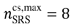
    Figure imgb4788
    .
  166. The apparatus according to claim 165, wherein in a case where the maximum number of cyclic shifts corresponding to the SRS resource is n SRS cs , max = 8
    Figure imgb4789
    , the cyclic shift offset value n SRS cs , i
    Figure imgb4790
    corresponding to the SRS sequence which is corresponding to the antenna port with the index of i among the N ap SRS
    Figure imgb4791
    antenna ports is determined based on one or more of:
    Figure imgb4792
    n SRS cs , i = n SRS cs + p i 1000 mod n SRS cs , max ;
    Figure imgb4793
    n SRS cs , i = n SRS cs + i mod n SRS cs , max ;
    Figure imgb4794
    Figure imgb4795
    n SRS cs , i = n SRS cs + 4 p i 1000 mod n SRS cs , max ;
    Figure imgb4796
    n SRS cs , i = n SRS cs + 4 i mod n SRS cs , max ;
    Figure imgb4797
    n SRS cs , i = n SRS cs + 2 n SRS cs , max N ap SRS p i 1000 mod n SRS cs , max ;
    Figure imgb4798
    n SRS cs , i = n SRS cs + 2 p i 1000 mod n SRS cs ,max ;
    Figure imgb4799
    n SRS cs , i = n SRS cs + 2 i mod n SRS cs ,max ;
    Figure imgb4800
    where n SRS cs
    Figure imgb4801
    is a cyclic shift configuration value.
  167. The apparatus according to claim 154, wherein before the reception unit receives the SRS corresponding to the configuration information and the transmission rule, the apparatus further comprises:
    a fifteenth determination unit configured to determine the SRS sequence which is corresponding to an antenna port with an index of i;
    wherein in a case where a maximum number of cyclic shifts corresponding to the SRS resource is n SRS cs ,max = 12
    Figure imgb4802
    , a cyclic shift offset value nSRS corresponding to the SRS sequence which is corresponding to the antenna port with the index of i among the N ap SRS
    Figure imgb4803
    antenna ports is determined based on one or more of:
    Figure imgb4804
    n SRS cs + p i 1000 ;
    Figure imgb4805
    n SRS cs + i ;
    Figure imgb4806
    Figure imgb4807
    3 p i 1000 ;
    Figure imgb4808
    3i;
    Figure imgb4809
    2i; 4 n SRS cs ,max N ap SRS p i 1000 ;
    Figure imgb4810
    4 p i 1000 ;
    Figure imgb4811
    4i;
    Figure imgb4812
    6 p i 1000 ;
    Figure imgb4813
    6i;
    where pi is a port index of the antenna port with the index of i, and i is an integer less than or equal to N ap SRS 1
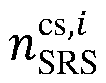
    Figure imgb4814
    .
  168. The apparatus according to claim 167, wherein in a case where the maximum number of cyclic shifts corresponding to the SRS resource is n SRS cs ,max = 12
    Figure imgb4815
    , the cyclic shift offset value n SRS cs , i
    Figure imgb4816
    corresponding to the SRS sequence which is corresponding to the antenna port with the index of i among the N ap SRS
    Figure imgb4817
    antenna ports is determined based on one or more of:
    Figure imgb4818
    n SRS cs , i = n SRS cs + p i 1000 mod n SRS cs ,max ;
    Figure imgb4819
    n SRS cs , i = n SRS cs + i mod n SRS cs ,max ;
    Figure imgb4820
    Figure imgb4821
    n SRS cs , i = n SRS cs + 3 p i 1000 mod n SRS cs ,max ;
    Figure imgb4822
    n SRS cs , i = n SRS cs + 3 i mod n SRS cs ,max ;
    Figure imgb4823
    n SRS cs , i = n SRS cs + 2 n SRS cs ,max N ap SRS p i 1000 mod n SRS cs ,max ;
    Figure imgb4824
    n SRS cs , i = n SRS cs + 2 p i 1000 mod n SRS cs ,max ;
    Figure imgb4825
    n SRS cs , i = n SRS cs + 2 i mod n SRS cs ,max ;
    Figure imgb4826
    n SRS cs , i = n SRS cs + 4 n SRS cs ,max N ap SRS p i 1000 mod n SRS cs ,max ;
    Figure imgb4827
    n SRS cs , i = n SRS cs + 4 p i 1000 mod n SRS cs ,max ;
    Figure imgb4828
    n SRS cs , i = n SRS cs + 4 i mod n SRS cs ,max ;
    Figure imgb4829
    Figure imgb4830
    n SRS cs , i = n SRS cs + 6 p i 1000 mod n SRS cs ,max ;
    Figure imgb4831
    n SRS cs , i = n SRS cs + 6 i mod n SRS cs ,max ;
    Figure imgb4832
    where n SRS cs
    Figure imgb4833
    is a cyclic shift configuration value.
  169. The apparatus according to claim 154, wherein before the reception unit receives the SRS corresponding to the configuration information and the transmission rule, the apparatus further comprises:
    a sixteenth determination unit configured to determine the SRS sequence which is corresponding to an antenna port with an index of i;
    wherein in a case where a maximum number of cyclic shifts corresponding to the SRS resource is n SRS cs ,max = 6
    Figure imgb4834
    , a cyclic shift offset value n SRS cs , i
    Figure imgb4835
    corresponding to the SRS sequence which is corresponding to the antenna port with the index of i among the N ap SRS
    Figure imgb4836
    antenna ports is determined based on one or more of:
    Figure imgb4837
    2 p i 1000 ;
    Figure imgb4838
    2i; n SRS cs ,max N ap SRS p i 1000 ;
    Figure imgb4839
    n SRS cs + p i 1000 ;
    Figure imgb4840
    Figure imgb4841
    4i; 3 n SRS cs ,max N ap SRS p i 1000 ;
    Figure imgb4842
    3 p i 1000 ;
    Figure imgb4843
    3i;
    where pi is a port index of the antenna port with the index of i, and i is an integer less than or equal to N ap SRS 1
    Figure imgb4844
    .
  170. The apparatus according to claim 169, wherein in a case where the maximum number of cyclic shifts corresponding to the SRS resource is n SRS cs ,max = 6
    Figure imgb4845
    , the cyclic shift offset value n SRS cs , i
    Figure imgb4846
    corresponding to the SRS sequence which is corresponding to the antenna port with the index of i among the N ap SRS
    Figure imgb4847
    antenna ports is determined based on one or more of: n SRS cs , i = n SRS cs + n SRS cs , max p i 1000 / 4 N ap SRS / 4 mod n SRS cs , max ;
    Figure imgb4848
    n SRS cs , i = n SRS cs + 2 n SRS cs , max N ap SRS p i 1000 mod n SRS cs , max ;
    Figure imgb4849
    n SRS cs , i = n SRS cs + 2 p i 1000 mod n SRS cs , max ;
    Figure imgb4850
    n SRS cs , i = n SRS cs + 2 i mod n SRS cs , max ;
    Figure imgb4851
    n SRS cs , i = n SRS cs + n SRS cs , max N ap SRS p i 1000 mod n SRS cs , max ;
    Figure imgb4852
    n SRS cs , i = n SRS cs + p i 1000 mod n SRS cs , max ;
    Figure imgb4853
    n SRS cs , i = n SRS cs + i mod n SRS cs , max ;
    Figure imgb4854
    n SRS cs , i = n SRS cs + 4 n SRS cs , max N ap SRS p i 1000 mod n SRS cs , max ;
    Figure imgb4855
    n SRS cs , i = n SRS cs + 4 p i 1000 mod n SRS cs , max ;
    Figure imgb4856
    n SRS cs , i = n SRS cs + 4 i mod n SRS cs , max ;
    Figure imgb4857
    n SRS cs , i = n SRS cs + 3 n SRS cs ,max N ap SRS p i 1000 mod n SRS cs ,max ;
    Figure imgb4858
    n SRS cs , i = n SRS cs + 3 p i 1000 mod n SRS cs ,max ;
    Figure imgb4859
    n SRS cs , i = n SRS cs + 3 i mod n SRS cs ,max ;
    Figure imgb4860
    where n SRS cs
    Figure imgb4861
    is a cyclic shift configuration value.
  171. The apparatus according to claim 154, wherein before the reception unit receives the SRS corresponding to the configuration information and the transmission rule, the apparatus further comprises:
    a seventeenth determination unit configured to determine the SRS sequence which is corresponding to an antenna port with an index of i;
    wherein in a case where a maximum number of cyclic shifts corresponding to the SRS resource is n SRS cs ,max = 16
    Figure imgb4862
    , a cyclic shift offset value n SRS cs , i
    Figure imgb4863
    corresponding to the SRS sequence which is corresponding to the antenna port with the index of i among the N ap SRS
    Figure imgb4864
    antenna ports is determined based on one or more of: 4 p i 1000 ;
    Figure imgb4865
    4i; 2 n SRS cs ,max N ap SRS p i 1000 ;
    Figure imgb4866
    2 p i 1000 ;
    Figure imgb4867
    2i;
    Figure imgb4868
    n SRS cs + p i 1000 ;
    Figure imgb4869
    n SRS cs + i ;
    Figure imgb4870
    Figure imgb4871
    3 p i 1000 ;
    Figure imgb4872
    3i; 4 n SRS cs ,max N ap SRS p i 1000 ;
    Figure imgb4873
    where pi is a port index of the antenna port with the index of i, and i is an integer less than or equal to N ap SRS 1
    Figure imgb4874
    .
  172. The apparatus according to claim 171, wherein in a case where the maximum number of cyclic shifts corresponding to the SRS resource is n SRS cs ,max = 16
    Figure imgb4875
    , the cyclic shift offset value n SRS cs , i
    Figure imgb4876
    corresponding to the SRS sequence which is corresponding to the antenna port with the index of i among the N ap SRS
    Figure imgb4877
    antenna ports is determined based on one or more of: n SRS cs , i = n SRS cs + 4 p i 1000 mod n SRS cs ,max ;
    Figure imgb4878
    n SRS cs , i = n SRS cs + 4 i mod n SRS cs ,max ;
    Figure imgb4879
    n SRS cs , i = n SRS cs + 2 n SRS cs ,max N ap SRS p i 1000 mod n SRS cs ,max ;
    Figure imgb4880
    n SRS cs , i = n SRS cs + 2 p i 1000 mod n SRS cs ,max ;
    Figure imgb4881
    n SRS cs , i = n SRS cs + 2 i mod n SRS cs ,max ;
    Figure imgb4882
    Figure imgb4883
    n SRS cs , i = n SRS cs + p i 1000 mod n SRS cs ,max ;
    Figure imgb4884
    n SRS cs , i = n SRS cs + i mod n SRS cs ,max ;
    Figure imgb4885
    Figure imgb4886
    n SRS cs , i = n SRS cs + 3 p i 1000 mod n SRS cs ,max ;
    Figure imgb4887
    n SRS cs , i = n SRS cs + 3 i mod n SRS cs ,max ;
    Figure imgb4888
    n SRS cs , i = n SRS cs + 4 n SRS cs ,max N ap SRS p i 1000 mod n SRS cs ,max ;
    Figure imgb4889
    where n SRS cs
    Figure imgb4890
    is a cyclic shift configuration value.
  173. The apparatus according to claim 154, wherein before the reception unit receives the SRS corresponding to the configuration information and the transmission rule, the apparatus further comprises:
    an eighteenth determination unit configured to determine the SRS sequence which is corresponding to an antenna port with an index of i;
    wherein a cyclic shift offset value n SRS cs , i
    Figure imgb4891
    corresponding to the SRS sequence which is corresponding to the antenna port with the index of i among the N ap SRS
    Figure imgb4892
    antenna ports is determined based on one or more of: n SRS cs ,max N ap SRS p i 1000 ;
    Figure imgb4893
    n SRS cs + p i 1000 ;
    Figure imgb4894
    n SRS cs + i ;
    Figure imgb4895
    3 n SRS cs ,max N ap SRS p i 1000 ;
    Figure imgb4896
    3 p i 1000 ;
    Figure imgb4897
    3i; 2 n SRS cs ,max N ap SRS p i 1000 ;
    Figure imgb4898
    2 p i 1000 ;
    Figure imgb4899
    2i; 4 n SRS cs ,max N ap SRS p i 1000 ;
    Figure imgb4900
    4 p i 1000 ;
    Figure imgb4901
    4i;
    Figure imgb4902
    6 p i 1000 ;
    Figure imgb4903
    6i;
    where pi is a port index of the antenna port with the index of i, and i is an integer less than or equal to N ap SRS 1
    Figure imgb4904
    .
  174. The apparatus according to claim 173, wherein the cyclic shift offset value n SRS cs , i
    Figure imgb4905
    corresponding to the SRS sequence which is corresponding to the antenna port with the index of i among the N ap SRS
    Figure imgb4906
    antenna ports is determined based on one or more of: n SRS cs , i = n SRS cs + n SRS cs ,max N ap SRS p i 1000 mod n SRS cs ,max ;
    Figure imgb4907
    n SRS cs , i = n SRS cs + p i 1000 mod n SRS cs ,max ;
    Figure imgb4908
    n SRS cs , i = n SRS cs + i mod n SRS cs ,max ;
    Figure imgb4909
    n SRS cs , i = n SRS cs + 3 n SRS cs ,max N ap SRS p i 1000 mod n SRS cs ,max ;
    Figure imgb4910
    n SRS cs , i = n SRS cs + 3 p i 1000 mod n SRS cs ,max ;
    Figure imgb4911
    n SRS cs , i = n SRS cs + 3 i mod n SRS cs ,max ;
    Figure imgb4912
    n SRS cs , i = n SRS cs + 2 n SRS cs ,max N ap SRS p i 1000 mod n SRS cs ,max ;
    Figure imgb4913
    n SRS cs , i = n SRS cs + 2 p i 1000 mod n SRS cs ,max ;
    Figure imgb4914
    n SRS cs , i = n SRS cs + 2 i mod n SRS cs ,max ;
    Figure imgb4915
    n SRS cs , i = n SRS cs + 4 n SRS cs ,max N ap SRS p i 1000 mod n SRS cs ,max ;
    Figure imgb4916
    n SRS cs , i = n SRS cs + 4 p i 1000 mod n SRS cs ,max ;
    Figure imgb4917
    n SRS cs , i = n SRS cs + 4 i mod n SRS cs ,max ;
    Figure imgb4918
    Figure imgb4919
    n SRS cs , i = n SRS cs + 6 p i 1000 mod n SRS cs ,max ;
    Figure imgb4920
    n SRS cs , i = n SRS cs + 6 i mod n SRS cs ,max ;
    Figure imgb4921
    where n SRS cs
    Figure imgb4922
    is a cyclic shift configuration value.
  175. The apparatus according to any one of claims 165 to 174, wherein the antenna ports in different antenna port groups adopt different formulas to determine the cyclic shift offset value.
  176. The apparatus according to claim 154, wherein the reception unit is configured to:
    receive the SRS sequence which is corresponding to an antenna port with an index of i, from a starting position of a frequency domain resource which is corresponding to a position parameter k TC p i
    Figure imgb4923
    of the frequency domain resource;
    wherein in a case where n SRS cs , max = 8 or 16
    Figure imgb4924
    , the position parameter k TC p i
    Figure imgb4925
    of the frequency domain resource corresponding to the antenna port with the index of i among the N ap SRS
    Figure imgb4926
    antenna ports is determined based on one or more of: k ¯ TC ;
    Figure imgb4927
    k ¯ TC + 3 ;
    Figure imgb4928
    k ¯ TC + 2 ;
    Figure imgb4929
    k ¯ TC + 1 ;
    Figure imgb4930
    k ¯ TC + 3 K TC / 4 ;
    Figure imgb4931
    k ¯ TC + 2 K TC / 4 ;
    Figure imgb4932
    k ¯ TC + K TC / 4 ;
    Figure imgb4933
    k ¯ TC + 4 ;
    Figure imgb4934
    where k TC is an offset of a comb in the frequency domain; and K TC is a transmission comb number.
  177. The apparatus according to claim 176, wherein in a case where n SRS cs ,max = 8 or 16
    Figure imgb4935
    , the position parameter k TC p i
    Figure imgb4936
    of the frequency domain resource corresponding to the antenna port with the index of i among the N ap SRS
    Figure imgb4937
    antenna ports is determined based on one or more of: k TC p i = k ¯ TC ;
    Figure imgb4938
    k TC p i = k ¯ TC + 3 mod K TC ;
    Figure imgb4939
    k TC p i = k ¯ TC + 2 mod K TC ;
    Figure imgb4940
    k TC p i = k ¯ TC + 1 mod K TC ;
    Figure imgb4941
    k TC p i = k ¯ TC + 3 K TC / 4 mod K TC ;
    Figure imgb4942
    k TC p i = k ¯ TC + 2 K TC / 4 mod K TC ;
    Figure imgb4943
    k TC p i = k ¯ TC + K TC / 4 mod K TC ;
    Figure imgb4944
    k TC p i = k ¯ TC + 4 mod K TC .
    Figure imgb4945
  178. The apparatus according to claim 154, wherein the reception unit is configured to:
    receive the SRS sequence which is corresponding to an antenna port with an index of i, from a starting position of a frequency domain resource which is corresponding to a position parameter k TC p i
    Figure imgb4946
    of the frequency domain resource;
    wherein in a case where n SRS cs ,max = 12 or 6
    Figure imgb4947
    , the position parameter k TC p i
    Figure imgb4948
    of the frequency domain resource corresponding to the antenna port with the index of i among the N ap SRS
    Figure imgb4949
    antenna ports is determined based on one or more of: k ¯ TC ;
    Figure imgb4950
    k ¯ TC + 3 ;
    Figure imgb4951
    k ¯ TC + 2 ;
    Figure imgb4952
    k ¯ TC + 1 ;
    Figure imgb4953
    k ¯ TC + 3 K TC / 4 ;
    Figure imgb4954
    k ¯ TC + 2 K TC / 4 ;
    Figure imgb4955
    k ¯ TC + K TC / 4 ;
    Figure imgb4956
    where k TC is an offset of a comb in the frequency domain; and K TC is a transmission comb number.
  179. The apparatus according to claim 178, wherein in a case where n SRS cs , max = 12 or 6
    Figure imgb4957
    , the position parameter k TC p i
    Figure imgb4958
    of the frequency domain resource corresponding to the antenna port with the index of i among the N ap SRS
    Figure imgb4959
    antenna ports is determined based on one or more of: k TC p i = k ¯ TC ;
    Figure imgb4960
    k TC p i = k ¯ TC + 3 mod K TC ;
    Figure imgb4961
    k TC p i = k ¯ TC + 2 mod K TC ;
    Figure imgb4962
    k TC p i = k ¯ TC + 1 mod K TC ;
    Figure imgb4963
    k TC p i = k ¯ TC + 3 K TC / 4 mod K TC ;
    Figure imgb4964
    k TC p i = k ¯ TC + 2 K TC / 4 mod K TC ;
    Figure imgb4965
    k TC p i = k ¯ TC + K TC / 4 mod K TC .
    Figure imgb4966
  180. The apparatus according to claim 154, wherein the reception unit is configured to:
    receive the SRS sequence which is corresponding to an antenna port with an index of i, from a starting position of a frequency domain resource which is corresponding to a position parameter k TC p i
    Figure imgb4967
    of the frequency domain resource;
    wherein the position parameter k TC p i
    Figure imgb4968
    of the frequency domain resource corresponding to the antenna port with the index of i among the N ap SRS
    Figure imgb4969
    antenna ports is determined based on one or more of: k ¯ TC + 3 ;
    Figure imgb4970
    k ¯ TC + 2 ;
    Figure imgb4971
    k ¯ TC + 1 ;
    Figure imgb4972
    k ¯ TC + 3 K TC / 4 ;
    Figure imgb4973
    k ¯ TC + K TC / 4 ;
    Figure imgb4974
    k ¯ TC + 4 ;
    Figure imgb4975
    where k TC is an offset of a comb in the frequency domain; and K TC is a transmission comb number.
  181. The apparatus according to claim 180, wherein the position parameter k TC p i
    Figure imgb4976
    of the frequency domain resource corresponding to the antenna port with the index of i among the N ap SRS
    Figure imgb4977
    antenna ports is determined based on one or more of: k TC p i = k ¯ TC + 3 mod K TC ;
    Figure imgb4978
    k TC p i = k ¯ TC + 2 mod K TC ;
    Figure imgb4979
    k TC p i = k ¯ TC + 1 mod K TC ;
    Figure imgb4980
    k TC p i = k ¯ TC + 3 K TC / 4 mod K TC ;
    Figure imgb4981
    k TC p i = k ¯ TC + K TC / 4 mod K TC ;
    Figure imgb4982
    k TC p i = k ¯ TC + 4 mod K TC .
    Figure imgb4983
  182. The apparatus according to any one of claims 176 to 181, wherein the antenna ports in different antenna port groups adopt different formulas to determine the cyclic shift offset value.
  183. The apparatus according to any one of claims 154 to 182, wherein the N ap SRS
    Figure imgb4984
    is valued as 8.
  184. A processor-readable storage medium, storing a computer program causing the processor to perform the method according to any one of claims 1 to 61.
EP23791320.7A 2022-04-20 2023-04-20 INFORMATION TRANSMISSION METHOD AND DEVICE AS WELL AS TERMINAL DEVICE AND NETWORK DEVICE Pending EP4513810A4 (en)

Applications Claiming Priority (2)

Application Number Priority Date Filing Date Title
CN202210419154.9A CN116996175A (en) 2022-04-20 2022-04-20 Information transmission methods, devices, terminal equipment and network equipment
PCT/CN2023/089525 WO2023202668A1 (en) 2022-04-20 2023-04-20 Information transmission method and apparatus, and terminal device and network device

Publications (2)

Publication Number Publication Date
EP4513810A1 true EP4513810A1 (en) 2025-02-26
EP4513810A4 EP4513810A4 (en) 2025-08-06

Family

ID=88419283

Family Applications (1)

Application Number Title Priority Date Filing Date
EP23791320.7A Pending EP4513810A4 (en) 2022-04-20 2023-04-20 INFORMATION TRANSMISSION METHOD AND DEVICE AS WELL AS TERMINAL DEVICE AND NETWORK DEVICE

Country Status (5)

Country Link
US (1) US20250293830A1 (en)
EP (1) EP4513810A4 (en)
CN (1) CN116996175A (en)
TW (1) TWI853536B (en)
WO (1) WO2023202668A1 (en)

Families Citing this family (1)

* Cited by examiner, † Cited by third party
Publication number Priority date Publication date Assignee Title
CN121239365A (en) * 2024-06-27 2025-12-30 华为技术有限公司 A reference signal transmission method and apparatus

Family Cites Families (5)

* Cited by examiner, † Cited by third party
Publication number Priority date Publication date Assignee Title
EP2663000B1 (en) * 2011-01-07 2019-05-01 Sun Patent Trust Transmitter, receiver, transmission method, and reception method
US11362788B2 (en) * 2018-01-24 2022-06-14 Lg Electronics Inc. Method for transmitting or receiving sounding reference signal in wireless communication system and apparatus therefor
CN111971915B (en) * 2018-04-28 2022-05-31 华为技术有限公司 Method for transmitting sounding reference signal and terminal equipment
CN111835488B (en) * 2019-08-15 2022-12-23 维沃移动通信有限公司 Method for determining mapping of antenna port and terminal
EP3820101A1 (en) * 2019-11-07 2021-05-12 FRAUNHOFER-GESELLSCHAFT zur Förderung der angewandten Forschung e.V. Ambiguity/aliasing cancellation or reduction for staggered reference signals

Also Published As

Publication number Publication date
WO2023202668A1 (en) 2023-10-26
EP4513810A4 (en) 2025-08-06
US20250293830A1 (en) 2025-09-18
CN116996175A (en) 2023-11-03
TW202344001A (en) 2023-11-01
TWI853536B (en) 2024-08-21

Similar Documents

Publication Publication Date Title
KR102464288B1 (en) Uplink power control method, terminal device and network device
EP4654487A2 (en) Transmission precoding matrix indication method and device
US20200195330A1 (en) Method and apparatus for transmitting downlink control information (dci)
WO2019137057A1 (en) Resource indication method, terminal device, and network device
EP3627747B1 (en) Information transmission method and apparatus
EP4383628A1 (en) Signal transmission method and apparatus, user equipment, network device, and storage medium
EP3573274A1 (en) Communication method and network device
CN117560125A (en) Frequency domain resource determination method, indication method, device, terminal and network equipment
US20250293830A1 (en) Information transmission method and apparatus, terminal device and network device
CN116669216A (en) PRACH repeated transmission method, equipment, device and storage medium
EP4597854A1 (en) Uplink transmission method, terminal, network device, apparatus, and storage medium
US20250393075A1 (en) Preamble sequence sending and receiving methods, apparatuses and storage medium
EP4572206A1 (en) Dmrs port determining method and apparatus, device, and storage medium
RU2844355C2 (en) Information transmission method and device, terminal device and network device
EP4668644A1 (en) Srs transmission method, device and apparatus, and storage medium
CN115333692B (en) DMRS port information determining method, device and storage medium
US20250294511A1 (en) Method for sending sidelink positioning reference signal, and terminal positioning method and apparatus
EP4572207A1 (en) Csi reporting method, terminal, network device, apparatus, and storage medium
US20250261187A1 (en) Information processing method, configuration method, apparatus, terminal, and network side device
EP4701317A1 (en) Random access method and apparatus
EP4572208A1 (en) Dmrs port determination method and apparatus, and storage medium
CN118785477B (en) Information processing method, device, terminal and network equipment
CN115915430B (en) Uplink control channel resource allocation method and device
EP4716316A1 (en) Srs transmission method, indication method, apparatus, terminal and network device
EP4598199A1 (en) Information determination method, apparatus, terminal and network device

Legal Events

Date Code Title Description
STAA Information on the status of an ep patent application or granted ep patent

Free format text: STATUS: THE INTERNATIONAL PUBLICATION HAS BEEN MADE

PUAI Public reference made under article 153(3) epc to a published international application that has entered the european phase

Free format text: ORIGINAL CODE: 0009012

STAA Information on the status of an ep patent application or granted ep patent

Free format text: STATUS: REQUEST FOR EXAMINATION WAS MADE

17P Request for examination filed

Effective date: 20241120

AK Designated contracting states

Kind code of ref document: A1

Designated state(s): AL AT BE BG CH CY CZ DE DK EE ES FI FR GB GR HR HU IE IS IT LI LT LU LV MC ME MK MT NL NO PL PT RO RS SE SI SK SM TR

DAV Request for validation of the european patent (deleted)
DAX Request for extension of the european patent (deleted)
A4 Supplementary search report drawn up and despatched

Effective date: 20250704

RIC1 Information provided on ipc code assigned before grant

Ipc: H04L 5/00 20060101AFI20250630BHEP