EP4513737A1 - Isolated ac-dc converter, charging device, and power supply system - Google Patents
Isolated ac-dc converter, charging device, and power supply system Download PDFInfo
- Publication number
- EP4513737A1 EP4513737A1 EP22949200.4A EP22949200A EP4513737A1 EP 4513737 A1 EP4513737 A1 EP 4513737A1 EP 22949200 A EP22949200 A EP 22949200A EP 4513737 A1 EP4513737 A1 EP 4513737A1
- Authority
- EP
- European Patent Office
- Prior art keywords
- shielding layer
- circuit
- filter
- pfc
- isolating
- Prior art date
- Legal status (The legal status is an assumption and is not a legal conclusion. Google has not performed a legal analysis and makes no representation as to the accuracy of the status listed.)
- Pending
Links
Images




Classifications
-
- H—ELECTRICITY
- H02—GENERATION; CONVERSION OR DISTRIBUTION OF ELECTRIC POWER
- H02M—APPARATUS FOR CONVERSION BETWEEN AC AND AC, BETWEEN AC AND DC, OR BETWEEN DC AND DC, AND FOR USE WITH MAINS OR SIMILAR POWER SUPPLY SYSTEMS; CONVERSION OF DC OR AC INPUT POWER INTO SURGE OUTPUT POWER; CONTROL OR REGULATION THEREOF
- H02M1/00—Details of apparatus for conversion
- H02M1/44—Circuits or arrangements for compensating for electromagnetic interference in converters or inverters
-
- H—ELECTRICITY
- H02—GENERATION; CONVERSION OR DISTRIBUTION OF ELECTRIC POWER
- H02M—APPARATUS FOR CONVERSION BETWEEN AC AND AC, BETWEEN AC AND DC, OR BETWEEN DC AND DC, AND FOR USE WITH MAINS OR SIMILAR POWER SUPPLY SYSTEMS; CONVERSION OF DC OR AC INPUT POWER INTO SURGE OUTPUT POWER; CONTROL OR REGULATION THEREOF
- H02M1/00—Details of apparatus for conversion
- H02M1/0067—Converter structures employing plural converter units, other than for parallel operation of the units on a single load
- H02M1/007—Plural converter units in cascade
-
- H—ELECTRICITY
- H02—GENERATION; CONVERSION OR DISTRIBUTION OF ELECTRIC POWER
- H02M—APPARATUS FOR CONVERSION BETWEEN AC AND AC, BETWEEN AC AND DC, OR BETWEEN DC AND DC, AND FOR USE WITH MAINS OR SIMILAR POWER SUPPLY SYSTEMS; CONVERSION OF DC OR AC INPUT POWER INTO SURGE OUTPUT POWER; CONTROL OR REGULATION THEREOF
- H02M1/00—Details of apparatus for conversion
- H02M1/0003—Details of control, feedback or regulation circuits
- H02M1/0038—Circuits or arrangements for suppressing, e.g. by masking incorrect turn-on or turn-off signals, e.g. due to current spikes in current mode control
-
- H—ELECTRICITY
- H02—GENERATION; CONVERSION OR DISTRIBUTION OF ELECTRIC POWER
- H02M—APPARATUS FOR CONVERSION BETWEEN AC AND AC, BETWEEN AC AND DC, OR BETWEEN DC AND DC, AND FOR USE WITH MAINS OR SIMILAR POWER SUPPLY SYSTEMS; CONVERSION OF DC OR AC INPUT POWER INTO SURGE OUTPUT POWER; CONTROL OR REGULATION THEREOF
- H02M1/00—Details of apparatus for conversion
- H02M1/0064—Magnetic structures combining different functions, e.g. storage, filtering or transformation
-
- H—ELECTRICITY
- H02—GENERATION; CONVERSION OR DISTRIBUTION OF ELECTRIC POWER
- H02M—APPARATUS FOR CONVERSION BETWEEN AC AND AC, BETWEEN AC AND DC, OR BETWEEN DC AND DC, AND FOR USE WITH MAINS OR SIMILAR POWER SUPPLY SYSTEMS; CONVERSION OF DC OR AC INPUT POWER INTO SURGE OUTPUT POWER; CONTROL OR REGULATION THEREOF
- H02M1/00—Details of apparatus for conversion
- H02M1/12—Arrangements for reducing harmonics from AC input or output
- H02M1/123—Suppression of common mode voltage or current
-
- H—ELECTRICITY
- H02—GENERATION; CONVERSION OR DISTRIBUTION OF ELECTRIC POWER
- H02M—APPARATUS FOR CONVERSION BETWEEN AC AND AC, BETWEEN AC AND DC, OR BETWEEN DC AND DC, AND FOR USE WITH MAINS OR SIMILAR POWER SUPPLY SYSTEMS; CONVERSION OF DC OR AC INPUT POWER INTO SURGE OUTPUT POWER; CONTROL OR REGULATION THEREOF
- H02M1/00—Details of apparatus for conversion
- H02M1/12—Arrangements for reducing harmonics from AC input or output
- H02M1/126—Arrangements for reducing harmonics from AC input or output using passive filters
-
- H—ELECTRICITY
- H02—GENERATION; CONVERSION OR DISTRIBUTION OF ELECTRIC POWER
- H02M—APPARATUS FOR CONVERSION BETWEEN AC AND AC, BETWEEN AC AND DC, OR BETWEEN DC AND DC, AND FOR USE WITH MAINS OR SIMILAR POWER SUPPLY SYSTEMS; CONVERSION OF DC OR AC INPUT POWER INTO SURGE OUTPUT POWER; CONTROL OR REGULATION THEREOF
- H02M1/00—Details of apparatus for conversion
- H02M1/42—Circuits or arrangements for compensating for or adjusting power factor in converters or inverters
- H02M1/4208—Arrangements for improving power factor of AC input
-
- H—ELECTRICITY
- H02—GENERATION; CONVERSION OR DISTRIBUTION OF ELECTRIC POWER
- H02M—APPARATUS FOR CONVERSION BETWEEN AC AND AC, BETWEEN AC AND DC, OR BETWEEN DC AND DC, AND FOR USE WITH MAINS OR SIMILAR POWER SUPPLY SYSTEMS; CONVERSION OF DC OR AC INPUT POWER INTO SURGE OUTPUT POWER; CONTROL OR REGULATION THEREOF
- H02M3/00—Conversion of DC power input into DC power output
- H02M3/22—Conversion of DC power input into DC power output with intermediate conversion into AC
- H02M3/24—Conversion of DC power input into DC power output with intermediate conversion into AC by static converters
- H02M3/28—Conversion of DC power input into DC power output with intermediate conversion into AC by static converters using discharge tubes with control electrode or semiconductor devices with control electrode to produce the intermediate AC
- H02M3/325—Conversion of DC power input into DC power output with intermediate conversion into AC by static converters using discharge tubes with control electrode or semiconductor devices with control electrode to produce the intermediate AC using devices of a triode or a transistor type requiring continuous application of a control signal
- H02M3/335—Conversion of DC power input into DC power output with intermediate conversion into AC by static converters using discharge tubes with control electrode or semiconductor devices with control electrode to produce the intermediate AC using devices of a triode or a transistor type requiring continuous application of a control signal using semiconductor devices only
- H02M3/33507—Conversion of DC power input into DC power output with intermediate conversion into AC by static converters using discharge tubes with control electrode or semiconductor devices with control electrode to produce the intermediate AC using devices of a triode or a transistor type requiring continuous application of a control signal using semiconductor devices only with automatic control of the output voltage or current, e.g. flyback converters
- H02M3/33523—Conversion of DC power input into DC power output with intermediate conversion into AC by static converters using discharge tubes with control electrode or semiconductor devices with control electrode to produce the intermediate AC using devices of a triode or a transistor type requiring continuous application of a control signal using semiconductor devices only with automatic control of the output voltage or current, e.g. flyback converters with galvanic isolation between input and output of both the power stage and the feedback loop
-
- H—ELECTRICITY
- H02—GENERATION; CONVERSION OR DISTRIBUTION OF ELECTRIC POWER
- H02M—APPARATUS FOR CONVERSION BETWEEN AC AND AC, BETWEEN AC AND DC, OR BETWEEN DC AND DC, AND FOR USE WITH MAINS OR SIMILAR POWER SUPPLY SYSTEMS; CONVERSION OF DC OR AC INPUT POWER INTO SURGE OUTPUT POWER; CONTROL OR REGULATION THEREOF
- H02M3/00—Conversion of DC power input into DC power output
- H02M3/22—Conversion of DC power input into DC power output with intermediate conversion into AC
- H02M3/24—Conversion of DC power input into DC power output with intermediate conversion into AC by static converters
- H02M3/28—Conversion of DC power input into DC power output with intermediate conversion into AC by static converters using discharge tubes with control electrode or semiconductor devices with control electrode to produce the intermediate AC
- H02M3/325—Conversion of DC power input into DC power output with intermediate conversion into AC by static converters using discharge tubes with control electrode or semiconductor devices with control electrode to produce the intermediate AC using devices of a triode or a transistor type requiring continuous application of a control signal
- H02M3/335—Conversion of DC power input into DC power output with intermediate conversion into AC by static converters using discharge tubes with control electrode or semiconductor devices with control electrode to produce the intermediate AC using devices of a triode or a transistor type requiring continuous application of a control signal using semiconductor devices only
- H02M3/33569—Conversion of DC power input into DC power output with intermediate conversion into AC by static converters using discharge tubes with control electrode or semiconductor devices with control electrode to produce the intermediate AC using devices of a triode or a transistor type requiring continuous application of a control signal using semiconductor devices only having several active switching elements
- H02M3/33573—Full-bridge at primary side of an isolation transformer
-
- H—ELECTRICITY
- H02—GENERATION; CONVERSION OR DISTRIBUTION OF ELECTRIC POWER
- H02M—APPARATUS FOR CONVERSION BETWEEN AC AND AC, BETWEEN AC AND DC, OR BETWEEN DC AND DC, AND FOR USE WITH MAINS OR SIMILAR POWER SUPPLY SYSTEMS; CONVERSION OF DC OR AC INPUT POWER INTO SURGE OUTPUT POWER; CONTROL OR REGULATION THEREOF
- H02M7/00—Conversion of AC power input into DC power output; Conversion of DC power input into AC power output
- H02M7/02—Conversion of AC power input into DC power output without possibility of reversal
- H02M7/04—Conversion of AC power input into DC power output without possibility of reversal by static converters
- H02M7/12—Conversion of AC power input into DC power output without possibility of reversal by static converters using discharge tubes with control electrode or semiconductor devices with control electrode
- H02M7/21—Conversion of AC power input into DC power output without possibility of reversal by static converters using discharge tubes with control electrode or semiconductor devices with control electrode using devices of a triode or transistor type requiring continuous application of a control signal
- H02M7/217—Conversion of AC power input into DC power output without possibility of reversal by static converters using discharge tubes with control electrode or semiconductor devices with control electrode using devices of a triode or transistor type requiring continuous application of a control signal using semiconductor devices only
- H02M7/2173—Conversion of AC power input into DC power output without possibility of reversal by static converters using discharge tubes with control electrode or semiconductor devices with control electrode using devices of a triode or transistor type requiring continuous application of a control signal using semiconductor devices only in a biphase or polyphase circuit arrangement
-
- H—ELECTRICITY
- H02—GENERATION; CONVERSION OR DISTRIBUTION OF ELECTRIC POWER
- H02M—APPARATUS FOR CONVERSION BETWEEN AC AND AC, BETWEEN AC AND DC, OR BETWEEN DC AND DC, AND FOR USE WITH MAINS OR SIMILAR POWER SUPPLY SYSTEMS; CONVERSION OF DC OR AC INPUT POWER INTO SURGE OUTPUT POWER; CONTROL OR REGULATION THEREOF
- H02M7/00—Conversion of AC power input into DC power output; Conversion of DC power input into AC power output
- H02M7/02—Conversion of AC power input into DC power output without possibility of reversal
- H02M7/04—Conversion of AC power input into DC power output without possibility of reversal by static converters
- H02M7/12—Conversion of AC power input into DC power output without possibility of reversal by static converters using discharge tubes with control electrode or semiconductor devices with control electrode
- H02M7/21—Conversion of AC power input into DC power output without possibility of reversal by static converters using discharge tubes with control electrode or semiconductor devices with control electrode using devices of a triode or transistor type requiring continuous application of a control signal
- H02M7/217—Conversion of AC power input into DC power output without possibility of reversal by static converters using discharge tubes with control electrode or semiconductor devices with control electrode using devices of a triode or transistor type requiring continuous application of a control signal using semiconductor devices only
- H02M7/219—Conversion of AC power input into DC power output without possibility of reversal by static converters using discharge tubes with control electrode or semiconductor devices with control electrode using devices of a triode or transistor type requiring continuous application of a control signal using semiconductor devices only in a bridge configuration
-
- H—ELECTRICITY
- H02—GENERATION; CONVERSION OR DISTRIBUTION OF ELECTRIC POWER
- H02J—ELECTRIC POWER NETWORKS; CIRCUIT ARRANGEMENTS OR SYSTEMS FOR SUPPLYING OR DISTRIBUTING ELECTRIC POWER; SYSTEMS FOR STORING ELECTRIC ENERGY
- H02J2207/00—Details of circuit arrangements for charging or discharging batteries or supplying loads from batteries
- H02J2207/20—Charging or discharging characterised by the power electronics converter
-
- H—ELECTRICITY
- H02—GENERATION; CONVERSION OR DISTRIBUTION OF ELECTRIC POWER
- H02J—ELECTRIC POWER NETWORKS; CIRCUIT ARRANGEMENTS OR SYSTEMS FOR SUPPLYING OR DISTRIBUTING ELECTRIC POWER; SYSTEMS FOR STORING ELECTRIC ENERGY
- H02J7/00—Circuit arrangements for charging or discharging batteries or for supplying loads from batteries
- H02J7/02—Circuit arrangements for charging or discharging batteries or for supplying loads from batteries for charging batteries from AC mains by converters
-
- H—ELECTRICITY
- H02—GENERATION; CONVERSION OR DISTRIBUTION OF ELECTRIC POWER
- H02M—APPARATUS FOR CONVERSION BETWEEN AC AND AC, BETWEEN AC AND DC, OR BETWEEN DC AND DC, AND FOR USE WITH MAINS OR SIMILAR POWER SUPPLY SYSTEMS; CONVERSION OF DC OR AC INPUT POWER INTO SURGE OUTPUT POWER; CONTROL OR REGULATION THEREOF
- H02M7/00—Conversion of AC power input into DC power output; Conversion of DC power input into AC power output
- H02M7/42—Conversion of DC power input into AC power output without possibility of reversal
- H02M7/44—Conversion of DC power input into AC power output without possibility of reversal by static converters
- H02M7/48—Conversion of DC power input into AC power output without possibility of reversal by static converters using discharge tubes with control electrode or semiconductor devices with control electrode
- H02M7/483—Converters with outputs that each can have more than two voltages levels
-
- Y—GENERAL TAGGING OF NEW TECHNOLOGICAL DEVELOPMENTS; GENERAL TAGGING OF CROSS-SECTIONAL TECHNOLOGIES SPANNING OVER SEVERAL SECTIONS OF THE IPC; TECHNICAL SUBJECTS COVERED BY FORMER USPC CROSS-REFERENCE ART COLLECTIONS [XRACs] AND DIGESTS
- Y02—TECHNOLOGIES OR APPLICATIONS FOR MITIGATION OR ADAPTATION AGAINST CLIMATE CHANGE
- Y02B—CLIMATE CHANGE MITIGATION TECHNOLOGIES RELATED TO BUILDINGS, e.g. HOUSING, HOUSE APPLIANCES OR RELATED END-USER APPLICATIONS
- Y02B70/00—Technologies for an efficient end-user side electric power management and consumption
- Y02B70/10—Technologies improving the efficiency by using switched-mode power supplies [SMPS], i.e. efficient power electronics conversion e.g. power factor correction or reduction of losses in power supplies or efficient standby modes
Definitions
- the present application relates to the technical field of power electronics, and in particular to an isolating AC-DC converter, a charging device and a power supply system.
- an isolating AC-DC converter adopts a two-stage architecture, with a first stage being a Power Factor Correction (PFC) circuit with a rectification function and a second stage being an isolating DC-DC circuit, which includes a transformer.
- PFC Power Factor Correction
- a primary winding and a secondary winding of the transformer may be connected in parallel with capacitors, or there may be a coupling capacitor between the primary winding and the secondary winding of the transformer.
- An interference source generated by the PFC circuit can be transferred to the secondary winding of the transformer through the capacitor, thereby forming a large common-mode loop channel, resulting in a decrease in the EMC performance of the isolating AC-DC converter.
- an AC EMC filter is added before the PFC circuit to increase the common-mode impedance.
- a high-impedance filter is required in the PFC circuit.
- the output needs to pass the EMC standard, it is also needed to add a high-impedance filter unit for the DC output as shown in FIG. 2 .
- the high-impedance EMC filter unit will inevitably bring disadvantages such as an increased cost, increased size and weight.
- an isolating AC-DC converter, a charging device and a power supply system are provided in the present application, which can improve the EMC performance without increasing the size and weight of the converter.
- An isolating AC-DC converter including: a PFC filter, a PFC circuit and a DC-DC circuit;
- the PFC filter includes a filter capacitor and a filter inductor; and the input terminal of the PFC circuit is connected to a first end of the filter inductor, a second end of the filter inductor is connected to a first end of the filter capacitor, and a second end of the filter capacitor is connected to the first shielding layer.
- the PFC filter includes a filter capacitor and a filter inductor; and the input terminal of the PFC circuit is connected to a first end of the filter inductor, a second end of the filter inductor is connected to a first end of the filter capacitor, and the second end of the filter inductor is connected to the first shielding layer.
- the isolating AC-DC converter further includes: a second shielding layer; and the second shielding layer is disposed between the primary winding and the first shielding layer, the second shielding layer is connected to a DC bus of the DC-DC circuit, and the second shielding layer is used to suppress an interference signal caused by a switch transistor of the primary winding of the DC-DC circuit.
- isolating AC-DC converter further includes: a third shielding layer; and the third shielding layer is disposed between the secondary winding and the first shielding layer, and the third shielding layer is connected to an end of an output capacitor of the DC-DC circuit.
- the first shielding layer is a copper foil located between the primary winding and the secondary winding, and an end of the copper foil is connected to the PFC filter through an electrical connection line.
- the isolating AC-DC converter is a three-phase converter or a single-phase converter.
- the input terminal of the PFC circuit is used to connect to a three-phase alternating current power
- the PFC circuit comprises a three-level circuit or a two-level circuit
- the DC-DC circuit comprises a DC-AC inverter bridge, the transformer and an AC-DC rectifier bridge; an input terminal of the DC-AC inverter bridge is connected to the output terminal of the PFC circuit, the primary winding of the transformer is connected to an output terminal of the DC-AC inverter bridge, and the secondary winding of the transformer is connected to an input terminal of the AC-DC rectifier bridge.
- a charging device is further provided in the present application, including the isolating AC-DC converter described above; and it further includes: a controller; where, the controller is used to control an output terminal of the isolating AC-DC converter to charge an electric device.
- a power supply system is further provided in the present application, including the isolating AC-DC converter described above; and it also includes: a controller; where the controller is used to control an output terminal of the isolating AC-DC converter to power an electric device.
- the isolating AC-DC converter includes: a PFC filter, a PFC circuit and a DC-DC circuit; where an input terminal of the PFC filter is connected to an AC power; an input terminal of the PFC circuit is connected to an output terminal of the PFC filter; an output terminal of the PFC circuit is connected to an input terminal of the DC-DC circuit;
- the DC-DC circuit comprises a transformer, and the transformer comprises a primary winding, a secondary winding, and a first shielding layer; and the first shielding layer is disposed between the primary winding and the secondary winding, and the first shielding layer is connected to the PFC filter to form a common mode loop, to block an interference signal from being transferred to the secondary winding, which reduces a common-mode current caused by the PFC circuit due to a coupling capacitance between the primary winding and the secondary winding of the transformer, and blocks an interference signal from being transferred to the secondary winding.
- the specific position, to which the first shielding layer is connected, of the PFC filter is not specifically limited.
- the first shielding layer may be connected to an end of the filter capacitor of the PFC filter, or it may be directly connected to a phase line of the AC input. Since the PFC filter generates an interference source, in order to prevent the interference source from being transferred to the secondary winding through the primary winding of the transformer, the interference signal of the primary winding of the transformer is transferred back to the PFC filter through the first shielding layer in the present application, thereby forming a common-mode loop and blocking the interference signal from being transferred to the secondary winding. In this solution, an additional EMC filter is not required, but only a shielding layer is added, which is easy to implement, and the size and volume will be not increased too much.
- An isolating AC-DC converter provided in an embodiment of the present application may be applied in many scenarios, such as communication power supply, and specifically it may be applied for powering a computer room. Further, it may also be applied to on-board chargers and charging stations. In the present application, a type of the load corresponding to the isolating AC-DC converter is not specifically limited.
- the isolating AC-DC converter provided in embodiments of the present application may be a three-phase converter or a single-phase converter.
- the isolating AC-DC converter is introduced below as a three-phase converter for example.
- FIG. 1 is a schematic diagram of an isolating AC-DC converter.
- the isolating AC-DC converter provided in the embodiments of the present application includes two stages, of which a first stage is a PFC circuit 100, and a second stage is a DC-DC circuit 200, where the DC-DC circuit 200 is isolating, that is, it includes a transformer T.
- a primary winding of the transformer T is connected to a DC-AC inverter bridge formed by a switch transistor, and a secondary winding of the transformer T is connected to an AC-DC rectifier bridge formed by a switch transistor.
- the interference source generated by the PFC circuit may be transferred to the secondary winding of the transformer T through a capacitance or a coupling capacitance of the transformer T to cause common-mode interference, resulting in reduction in the EMC performance of the entire isolating AC-DC converter, generally, in order to improve the EMC performance, in the isolating AC-DC converter shown in FIG. 2 , an AC EMC filter 400 is added before the PFC circuit 100, generally at an input terminal of the PFC filter 300, and sometimes a DC EMC filter 500 may be added at an output terminal of the DC-DC circuit 200. Since the EMC filter generally includes an inductor, the volume of the entire circuit will be larger, the weight will be increased accordingly, and the cost will be higher.
- the PFC filter 300 is a differential mode filter, which is mainly used to filter out differential mode interference.
- the EMC filter is not added, but a shielding layer is added between the primary winding and the secondary winding of the transformer, to shield the interference source of the PFC circuit, and prevent the interference signal from being transferred to the secondary winding of the transformer and a circuit of the secondary winding through the transformer to impose an impact on the load.
- FIG. 3 is a schematic diagram of an isolating AC-DC converter provided in an embodiment of the present application.
- the isolating AC-DC converter provided in this embodiment includes a PFC filter 300, a PFC circuit 100, and a DC-DC circuit 200; where,
- a specific implementation form of a rectifier circuit and an inverter circuit in the DC-DC circuit 200 is not specifically limited in the embodiments of the present application, and it may be a full bridge or a half bridge. In the present embodiment, introduction will be specifically made by taking a DC-DC circuit 200 including a DC-AC inverter 201 and an AC-DC rectifier 202 as an example.
- the first shielding layer 10 is disposed between the primary winding and the secondary winding.
- the first shielding layer 10 is connected to the PFC filter 300 to form a common mode loop, to block an interference signal from being transferred to the secondary winding.
- specific material of the first shielding layer 10 is not specifically limited, for example, it may be a conductive material such as a copper foil.
- a specific position, to which the first shielding layer 10 is connected, of the PFC filter 300 is not specifically limited.
- the first shielding layer 10 may be connected to an end of a filter capacitor of the PFC filter 300. Since the PFC filter 300 generates an interference source, in order to prevent the interference source from being transferred to the secondary winding through the primary winding of the transformer T, the interference signal of the primary winding of the transformer T is transferred back to the PFC filter 300 through the first shielding layer 10 in the present application, thereby forming a common mode loop, to block the interference signal from being transferred to the secondary winding.
- the specific position, to which the first shielding layer is connected, of the PFC filter is not specifically limited.
- the first shielding layer may be connected to an end of the filter capacitor of the PFC filter, or it may be directly connected to a phase line of the AC input.
- an additional EMC filter is not required, but only a shielding layer is added, which is easy to implement, and the size and volume will be not increased too much.
- the secondary winding of the transformer T is connected to the AC-DC rectifier 202, and a secondary winding of the AC-DC rectifier 202 outputs DC to power the load.
- the isolating AC-DC converter shown in FIG. 4 is a specific implementation of FIG. 3 .
- FIG. 4 describes a three-phase isolating AC-DC converter as an example. It should be understood that the isolating AC-DC converter may also be a single-phase converter.
- the filter circuit in FIG. 4 includes three filter capacitors C and three filter inductors L.
- An input terminal of the PFC circuit is connected to a first end of the filter inductor L, a second end of the filter inductor L is connected to a first end of the filter capacitor C, and a second end of the filter capacitor C is connected to a first shielding layer 10.
- FIG. 5 is an equivalent circuit diagram provided in an embodiment of the present application.
- Vd is an interference source generated by the PFC circuit. According to the voltage division principle, a divided voltage of the interference source Vd between points A and B is low. If Ld is not considered, Cd in uF and C1 in tens of pF differ from each other by five orders of magnitude. It can be seen that a voltage component, leaked from the isolating AC-DC converter, of the interference source is only 1/100,000 of the original interference source, which reduces the interference of the interference source on the secondary side of the transformer. Meanwhile, because C1 is a capacitor in pF, an interference current generated by Vd in the loop is suppressed, suppressing a risk caused by an excessive interference current.
- the second end of the first shielding layer 10 in FIG. 4 is connected to the capacitor of the PFC filter.
- the first shielding layer may also be directly connected to a phase line of one phase of the AC input.
- FIG. 6 is a schematic diagram of another isolating AC-DC converter provided in an embodiment of the present application.
- FIG. 6 The difference between FIG. 6 and FIG. 4 is that the second end of the first shielding layer 10 is connected to a different position.
- the PFC filter includes a filter capacitor C and a filter inductor L.
- An input terminal of the PFC circuit is connected to the first end of a filter inductor L, a second end of the filter inductor L is connected to a first end of the filter capacitor C, and a second end of the filter inductor L is connected to the first shielding layer 10.
- Bothe of the first shielding layers in FIG. 4 and FIG. 6 described in the above embodiments may reduce the interference of the interference source on the secondary circuit of the transformer, and the second end thereof may be connected to a static point. That is, the interference source is led back to the static point, thereby reducing the current of the interference loop and protecting the circuit device, as long as one end of the first shielding layer is connected into the PFC filter or to the input terminal of the PFC filter.
- a second shielding layer may be further added in the transformer, which is described in detail below in conjunction with the accompanying drawings.
- FIG. 7 is a schematic diagram of yet another isolating AC-DC converter provided in an embodiment of the present application.
- the isolating AC-DC converter provided in this embodiment further includes a second shielding layer 20.
- the second shielding layer 20 is disposed between the primary winding and the first shielding layer 10, and the second shielding layer 20 is connected to a DC bus of a DC-DC circuit.
- the second shielding layer 20 is used to suppress an interference signal of the primary switch transistor of the DC-DC circuit.
- the material of the second shielding layer 20 is not specifically limited. For example, it may be the same as the material of the first shielding layer.
- the second end of the second shielding layer 20 may be connected to a negative terminal of the DC bus of the DC-DC circuit. That is, when the interference signal generated by the switch transistor of the DC-DC circuit is led back to the DC bus of the input end of the DC-DC circuit.
- the first shielding layer 10 may also isolate the interference of the primary winding of the DC-DC circuit to the secondary winding to a certain extent, that is, suppress the interference signal of the primary winding of the DC-DC circuit in the primary winding loop.
- the second shielding layer 20 added in this embodiment may better reduce the interference signal generated by the primary switch of the DC-DC circuit, reduce a number of devices affected by the interference signal and the area as surrounded, and further reduce the interference signal of the isolating AC-DC converter.
- a third shielding layer may be added, and the third shielding layer is connected to a certain point of an output capacitor of the secondary winding of the transformer.
- the third shielding layer is located between the secondary winding and the first shielding layer.
- FIG. 8 is a schematic diagram of still another isolating AC-DC converter provided by an embodiment of the present application.
- the isolating AC-DC converter provided by this embodiment further includes a third shielding layer 30.
- the third shielding layer 30 is disposed between the secondary winding and the first shielding layer 10, and the third shielding layer 30 is connected to an end of an output capacitor of the DC-DC circuit, that is, to an output terminal of a rectifier connected with the secondary winding of the transformer of the DC-DC circuit, for example, a negative output terminal of the rectifier in FIG. 8 . Since the output capacitor is connected to the output terminal of the rectifier, the second end of the third shielding layer 30 is also connected to an end of the output capacitor.
- the negative output terminal of the rectifier is also a static point, and introducing the interference signal into the static point may effectively reduce an influence by a rectifier tube in the rectifier on the primary winding of the transformer.
- FIG. 8 only shows a situation where the first shielding layer 10 and the third shielding layer 30 are used in combination. It should be understood that the three shielding layers may be used in combination.
- FIG. 9 is a schematic diagram of another isolating AC-DC converter provided by an embodiment of the present application.
- FIG. 9 shows a situation where the first shielding layer 10, the second shielding layer 20, and the third shielding layer 30 are used in combination, which may not only shield the interference caused by the PFC filter, but also shield the interference caused by the primary switch and the secondary switch of the DC-DC circuit.
- the PFC circuit being a half-bridge circuit as an example.
- the PFC circuit may also be a circuit of other forms, and is not limited to a two-level circuit or a three-level circuit.
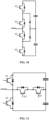
- FIG. 10 shows a three-level PFC circuit.
- the four switch transistors Q1-Q4 in FIG. 10 are controllable switch transistors. It should be understood that Q1 and Q4 may also be diodes.
- the circuit shown in FIG. 10 is an I-type three-level circuit, and may also be a T-type three-level circuit.
- FIG. 11 which includes four controllable switch transistors. It should be understood that Q1 and Q2 may be replaced by diodes.
- the PFC circuit may also be a circuit shown in FIG. 12 .
- a charging device is further provided in an embodiment of the present application, which is described in detail below in conjunction with the accompanying drawings.
- FIG. 13 is a schematic diagram of a charging device provided in an embodiment of the present application.
- the charging device 1000 provided in this embodiment includes any of the isolating AC-DC converters 2000 described in the above embodiments; and it further includes: a controller 3000.
- the charging device may be a charging station or an on-board charger.
- AC is input and DC is output, which is used to charge an electric vehicle.
- the charging device When the charging device is an on-board charger, it may charge the vehicle while driving, such as an electric bus.
- the controller 3000 is configured to control an output of the isolating AC-DC converter to supply power to an electric device.
- the electric device may be a load in a computer room, such as an air conditioner in a computer room, a server in a computer room, or a load in a digital center, and so on.
- the electric device may also be a communication device.
- the power supply system provided by the embodiments of the present application may better shield interference signals, a higher quality power supply may be provided to the load.
Landscapes
- Engineering & Computer Science (AREA)
- Power Engineering (AREA)
- Physics & Mathematics (AREA)
- Electromagnetism (AREA)
- Dc-Dc Converters (AREA)
- Rectifiers (AREA)
Abstract
Description
- The present application claims priority to
Chinese Patent Application No. 202210743957.X, titled "ISOLATED AC-DC CONVERTER, CHARGING DEVICE, AND POWER SUPPLY SYSTEM", filed on June 28, 2022 - The present application relates to the technical field of power electronics, and in particular to an isolating AC-DC converter, a charging device and a power supply system.
- At present, an isolating AC-DC converter adopts a two-stage architecture, with a first stage being a Power Factor Correction (PFC) circuit with a rectification function and a second stage being an isolating DC-DC circuit, which includes a transformer.
- In practical applications, a primary winding and a secondary winding of the transformer may be connected in parallel with capacitors, or there may be a coupling capacitor between the primary winding and the secondary winding of the transformer. An interference source generated by the PFC circuit can be transferred to the secondary winding of the transformer through the capacitor, thereby forming a large common-mode loop channel, resulting in a decrease in the EMC performance of the isolating AC-DC converter.
- In order to improve the EMC performance, an AC EMC filter is added before the PFC circuit to increase the common-mode impedance. However, in order to meet the EMC standard, a high-impedance filter is required in the PFC circuit. In situations where the output needs to pass the EMC standard, it is also needed to add a high-impedance filter unit for the DC output as shown in
FIG. 2 . The high-impedance EMC filter unit will inevitably bring disadvantages such as an increased cost, increased size and weight. - In order to solve the above technical problems, an isolating AC-DC converter, a charging device and a power supply system are provided in the present application, which can improve the EMC performance without increasing the size and weight of the converter.
- An isolating AC-DC converter is provided in the present application, including: a PFC filter, a PFC circuit and a DC-DC circuit; where,
- an input terminal of the PFC filter is connected to an AC power;
- an input terminal of the PFC circuit is connected to an output terminal of the PFC filter;
- an output terminal of the PFC circuit is connected to an input terminal of the DC-DC circuit;
- the DC-DC circuit comprises a transformer, and the transformer comprises a primary winding, a secondary winding, and a first shielding layer; and
- the first shielding layer is disposed between the primary winding and the secondary winding, and the first shielding layer is connected to the PFC filter to form a common mode loop, to block an interference signal from being transferred to the secondary winding.
- Preferably, the PFC filter includes a filter capacitor and a filter inductor; and
the input terminal of the PFC circuit is connected to a first end of the filter inductor, a second end of the filter inductor is connected to a first end of the filter capacitor, and a second end of the filter capacitor is connected to the first shielding layer. - Preferably, the PFC filter includes a filter capacitor and a filter inductor; and
the input terminal of the PFC circuit is connected to a first end of the filter inductor, a second end of the filter inductor is connected to a first end of the filter capacitor, and the second end of the filter inductor is connected to the first shielding layer. - Preferably, the isolating AC-DC converter further includes: a second shielding layer; and
the second shielding layer is disposed between the primary winding and the first shielding layer, the second shielding layer is connected to a DC bus of the DC-DC circuit, and the second shielding layer is used to suppress an interference signal caused by a switch transistor of the primary winding of the DC-DC circuit. - Preferably, isolating AC-DC converter further includes: a third shielding layer; and the third shielding layer is disposed between the secondary winding and the first shielding layer, and the third shielding layer is connected to an end of an output capacitor of the DC-DC circuit.
- Preferably, the first shielding layer is a copper foil located between the primary winding and the secondary winding, and an end of the copper foil is connected to the PFC filter through an electrical connection line.
- Preferably, the isolating AC-DC converter is a three-phase converter or a single-phase converter.
- Preferably, the input terminal of the PFC circuit is used to connect to a three-phase alternating current power, and the PFC circuit comprises a three-level circuit or a two-level circuit; and
the DC-DC circuit comprises a DC-AC inverter bridge, the transformer and an AC-DC rectifier bridge; an input terminal of the DC-AC inverter bridge is connected to the output terminal of the PFC circuit, the primary winding of the transformer is connected to an output terminal of the DC-AC inverter bridge, and the secondary winding of the transformer is connected to an input terminal of the AC-DC rectifier bridge. - A charging device is further provided in the present application, including the isolating AC-DC converter described above; and it further includes: a controller; where,
the controller is used to control an output terminal of the isolating AC-DC converter to charge an electric device. - A power supply system is further provided in the present application, including the isolating AC-DC converter described above; and it also includes: a controller; where the controller is used to control an output terminal of the isolating AC-DC converter to power an electric device.
- It can be seen that the present application has the following beneficial effects.
- The isolating AC-DC converter provided by the present application includes: a PFC filter, a PFC circuit and a DC-DC circuit; where an input terminal of the PFC filter is connected to an AC power; an input terminal of the PFC circuit is connected to an output terminal of the PFC filter; an output terminal of the PFC circuit is connected to an input terminal of the DC-DC circuit; the DC-DC circuit comprises a transformer, and the transformer comprises a primary winding, a secondary winding, and a first shielding layer; and the first shielding layer is disposed between the primary winding and the secondary winding, and the first shielding layer is connected to the PFC filter to form a common mode loop, to block an interference signal from being transferred to the secondary winding, which reduces a common-mode current caused by the PFC circuit due to a coupling capacitance between the primary winding and the secondary winding of the transformer, and blocks an interference signal from being transferred to the secondary winding. In the present application, the specific position, to which the first shielding layer is connected, of the PFC filter is not specifically limited. For example, the first shielding layer may be connected to an end of the filter capacitor of the PFC filter, or it may be directly connected to a phase line of the AC input. Since the PFC filter generates an interference source, in order to prevent the interference source from being transferred to the secondary winding through the primary winding of the transformer, the interference signal of the primary winding of the transformer is transferred back to the PFC filter through the first shielding layer in the present application, thereby forming a common-mode loop and blocking the interference signal from being transferred to the secondary winding. In this solution, an additional EMC filter is not required, but only a shielding layer is added, which is easy to implement, and the size and volume will be not increased too much.
-
-
FIG. 1 is a schematic diagram of an isolating AC-DC converter; -
FIG. 2 is a schematic diagram of an isolating AC-DC converter with an EMC filter; -
FIG. 3 is a schematic diagram of an isolating AC-DC converter provided in an embodiment of the present application; -
FIG. 4 is a circuit diagram of a specific isolating AC-DC converter ofFIG. 3 ; -
FIG. 5 is an equivalent circuit diagram provided in an embodiment of the present application; -
FIG. 6 is a schematic diagram of another isolating AC-DC converter provided in an embodiment of the present application; -
FIG. 7 is a schematic diagram of yet another isolating AC-DC converter provided in an embodiment of the present application; -
FIG. 8 is a schematic diagram of still another isolating AC-DC converter provided in an embodiment of the present application; -
FIG. 9 is a schematic diagram of another isolating AC-DC converter provided in an embodiment of the present application; -
FIG. 10 is a schematic diagram of a PFC circuit provided in an embodiment of the present application; -
FIG. 11 is a schematic diagram of another PFC circuit provided in an embodiment of the present application; -
FIG. 12 is a schematic diagram of yet another PFC circuit provided in an embodiment of the present application; -
FIG. 13 is a schematic diagram of a charging device provided in an embodiment of the present application; and -
FIG. 14 is a schematic diagram of a power supply system provided in an embodiment of the present application. - In order to make those skilled in the art to better understand the technical solution provided by the present application, specific application scenarios are introduced below.
- An isolating AC-DC converter provided in an embodiment of the present application may be applied in many scenarios, such as communication power supply, and specifically it may be applied for powering a computer room. Further, it may also be applied to on-board chargers and charging stations. In the present application, a type of the load corresponding to the isolating AC-DC converter is not specifically limited.
- The isolating AC-DC converter provided in embodiments of the present application may be a three-phase converter or a single-phase converter. The isolating AC-DC converter is introduced below as a three-phase converter for example.
- Reference is made to
FIG. 1 , which is a schematic diagram of an isolating AC-DC converter. - The isolating AC-DC converter provided in the embodiments of the present application includes two stages, of which a first stage is a
PFC circuit 100, and a second stage is a DC-DC circuit 200, where the DC-DC circuit 200 is isolating, that is, it includes a transformer T. A primary winding of the transformer T is connected to a DC-AC inverter bridge formed by a switch transistor, and a secondary winding of the transformer T is connected to an AC-DC rectifier bridge formed by a switch transistor. - Since the interference source generated by the PFC circuit may be transferred to the secondary winding of the transformer T through a capacitance or a coupling capacitance of the transformer T to cause common-mode interference, resulting in reduction in the EMC performance of the entire isolating AC-DC converter, generally, in order to improve the EMC performance, in the isolating AC-DC converter shown in
FIG. 2 , anAC EMC filter 400 is added before thePFC circuit 100, generally at an input terminal of thePFC filter 300, and sometimes aDC EMC filter 500 may be added at an output terminal of the DC-DC circuit 200. Since the EMC filter generally includes an inductor, the volume of the entire circuit will be larger, the weight will be increased accordingly, and the cost will be higher. ThePFC filter 300 is a differential mode filter, which is mainly used to filter out differential mode interference. - In the isolating AC-DC converter provided in the embodiments of the present application, the EMC filter is not added, but a shielding layer is added between the primary winding and the secondary winding of the transformer, to shield the interference source of the PFC circuit, and prevent the interference signal from being transferred to the secondary winding of the transformer and a circuit of the secondary winding through the transformer to impose an impact on the load.
- The isolating AC-DC converter provided in the embodiments of the present application is described in detail below in conjunction with the accompanying drawings.
- Reference is made to
FIG. 3 , which is a schematic diagram of an isolating AC-DC converter provided in an embodiment of the present application. - The isolating AC-DC converter provided in this embodiment includes a
PFC filter 300, aPFC circuit 100, and a DC-DC circuit 200; where, - an input terminal of the
PFC filter 300 is connected to an AC power; - an input terminal of the
PFC circuit 100 is connected to an output terminal of thePFC filter 300; - an output terminal of the
PFC circuit 100 is connected to an input terminal of the DC-DC circuit 200; and - the DC-
DC circuit 200 includes a transformer T, and the transformer T includes a primary winding, a secondary winding, and afirst shielding layer 10. - A specific implementation form of a rectifier circuit and an inverter circuit in the DC-
DC circuit 200 is not specifically limited in the embodiments of the present application, and it may be a full bridge or a half bridge. In the present embodiment, introduction will be specifically made by taking a DC-DC circuit 200 including a DC-AC inverter 201 and an AC-DC rectifier 202 as an example. - The
first shielding layer 10 is disposed between the primary winding and the secondary winding. Thefirst shielding layer 10 is connected to thePFC filter 300 to form a common mode loop, to block an interference signal from being transferred to the secondary winding. - In the embodiments of the present application, specific material of the
first shielding layer 10 is not specifically limited, for example, it may be a conductive material such as a copper foil. - In the embodiments of the present application, a specific position, to which the
first shielding layer 10 is connected, of thePFC filter 300 is not specifically limited. For example, thefirst shielding layer 10 may be connected to an end of a filter capacitor of thePFC filter 300. Since thePFC filter 300 generates an interference source, in order to prevent the interference source from being transferred to the secondary winding through the primary winding of the transformer T, the interference signal of the primary winding of the transformer T is transferred back to thePFC filter 300 through thefirst shielding layer 10 in the present application, thereby forming a common mode loop, to block the interference signal from being transferred to the secondary winding. In the present application, the specific position, to which the first shielding layer is connected, of the PFC filter is not specifically limited. For example, the first shielding layer may be connected to an end of the filter capacitor of the PFC filter, or it may be directly connected to a phase line of the AC input. In this solution, an additional EMC filter is not required, but only a shielding layer is added, which is easy to implement, and the size and volume will be not increased too much. - The secondary winding of the transformer T is connected to the AC-
DC rectifier 202, and a secondary winding of the AC-DC rectifier 202 outputs DC to power the load. - The isolating AC-DC converter shown in
FIG. 4 is a specific implementation ofFIG. 3 . -
FIG. 4 describes a three-phase isolating AC-DC converter as an example. It should be understood that the isolating AC-DC converter may also be a single-phase converter. - The filter circuit in
FIG. 4 includes three filter capacitors C and three filter inductors L. - An input terminal of the PFC circuit is connected to a first end of the filter inductor L, a second end of the filter inductor L is connected to a first end of the filter capacitor C, and a second end of the filter capacitor C is connected to a
first shielding layer 10. - The operating principle of the isolating AC-DC converter provided in the embodiments of the present application is introduced below in conjunction with
FIG. 5 . - Reference is made to
FIG. 5 , which is an equivalent circuit diagram provided in an embodiment of the present application. - The first capacitor C1 is a coupling capacitor between the primary winding of the transformer and the first shielding layer, which is generally tens of pF, and the second capacitor C2 is a coupling capacitor between the first shielding layer and the secondary winding of the transformer. Ld is an equivalent inductance of the PFC filter, and Cd is an equivalent capacitance of the PFC filter, which generally has an uF scale. The PFC filter mainly filters out a differential mode signal, and thus Ld may be referred to as a differential mode inductance and Cd may be referred to as a differential mode capacitance.
- Vd is an interference source generated by the PFC circuit. According to the voltage division principle, a divided voltage of the interference source Vd between points A and B is low. If Ld is not considered, Cd in uF and C1 in tens of pF differ from each other by five orders of magnitude. It can be seen that a voltage component, leaked from the isolating AC-DC converter, of the interference source is only 1/100,000 of the original interference source, which reduces the interference of the interference source on the secondary side of the transformer. Meanwhile, because C1 is a capacitor in pF, an interference current generated by Vd in the loop is suppressed, suppressing a risk caused by an excessive interference current.
- The second end of the
first shielding layer 10 inFIG. 4 is connected to the capacitor of the PFC filter. In addition, the first shielding layer may also be directly connected to a phase line of one phase of the AC input. - Reference is made to
FIG. 6 , which is a schematic diagram of another isolating AC-DC converter provided in an embodiment of the present application. - The difference between
FIG. 6 and FIG. 4 is that the second end of thefirst shielding layer 10 is connected to a different position. - The PFC filter includes a filter capacitor C and a filter inductor L.
- An input terminal of the PFC circuit is connected to the first end of a filter inductor L, a second end of the filter inductor L is connected to a first end of the filter capacitor C, and a second end of the filter inductor L is connected to the
first shielding layer 10. - Bothe of the first shielding layers in
FIG. 4 and FIG. 6 described in the above embodiments may reduce the interference of the interference source on the secondary circuit of the transformer, and the second end thereof may be connected to a static point. That is, the interference source is led back to the static point, thereby reducing the current of the interference loop and protecting the circuit device, as long as one end of the first shielding layer is connected into the PFC filter or to the input terminal of the PFC filter. - In addition, in order to suppress the interference caused by the primary switch transistor of the DC-DC circuit, in an embodiment of the present application, a second shielding layer may be further added in the transformer, which is described in detail below in conjunction with the accompanying drawings.
- Reference is made to
FIG. 7 , which is a schematic diagram of yet another isolating AC-DC converter provided in an embodiment of the present application. - The isolating AC-DC converter provided in this embodiment further includes a
second shielding layer 20. - The
second shielding layer 20 is disposed between the primary winding and thefirst shielding layer 10, and thesecond shielding layer 20 is connected to a DC bus of a DC-DC circuit. Thesecond shielding layer 20 is used to suppress an interference signal of the primary switch transistor of the DC-DC circuit. - In the embodiments of the present application, the material of the
second shielding layer 20 is not specifically limited. For example, it may be the same as the material of the first shielding layer. - Specifically, in a possible implementation, the second end of the
second shielding layer 20 may be connected to a negative terminal of the DC bus of the DC-DC circuit. That is, when the interference signal generated by the switch transistor of the DC-DC circuit is led back to the DC bus of the input end of the DC-DC circuit. It should be understood that thefirst shielding layer 10 may also isolate the interference of the primary winding of the DC-DC circuit to the secondary winding to a certain extent, that is, suppress the interference signal of the primary winding of the DC-DC circuit in the primary winding loop. However, thesecond shielding layer 20 added in this embodiment may better reduce the interference signal generated by the primary switch of the DC-DC circuit, reduce a number of devices affected by the interference signal and the area as surrounded, and further reduce the interference signal of the isolating AC-DC converter. - In addition, in order to suppress an influence of the secondary switch of the isolating DC-DC circuit on the primary winding of the transformer, in an embodiment of the present application, a third shielding layer may be added, and the third shielding layer is connected to a certain point of an output capacitor of the secondary winding of the transformer. The third shielding layer is located between the secondary winding and the first shielding layer.
- Reference is made to
FIG. 8 , which is a schematic diagram of still another isolating AC-DC converter provided by an embodiment of the present application. - The isolating AC-DC converter provided by this embodiment further includes a
third shielding layer 30. - The
third shielding layer 30 is disposed between the secondary winding and thefirst shielding layer 10, and thethird shielding layer 30 is connected to an end of an output capacitor of the DC-DC circuit, that is, to an output terminal of a rectifier connected with the secondary winding of the transformer of the DC-DC circuit, for example, a negative output terminal of the rectifier inFIG. 8 . Since the output capacitor is connected to the output terminal of the rectifier, the second end of thethird shielding layer 30 is also connected to an end of the output capacitor. The negative output terminal of the rectifier is also a static point, and introducing the interference signal into the static point may effectively reduce an influence by a rectifier tube in the rectifier on the primary winding of the transformer. -
FIG. 8 only shows a situation where thefirst shielding layer 10 and thethird shielding layer 30 are used in combination. It should be understood that the three shielding layers may be used in combination. Reference is made toFIG. 9 , which is a schematic diagram of another isolating AC-DC converter provided by an embodiment of the present application. -
FIG. 9 shows a situation where thefirst shielding layer 10, thesecond shielding layer 20, and thethird shielding layer 30 are used in combination, which may not only shield the interference caused by the PFC filter, but also shield the interference caused by the primary switch and the secondary switch of the DC-DC circuit. - The above embodiments of the present application are introduced by taking the PFC circuit being a half-bridge circuit as an example. In addition, the PFC circuit may also be a circuit of other forms, and is not limited to a two-level circuit or a three-level circuit.
- Reference is made to
FIG. 10 , which shows a three-level PFC circuit. The four switch transistors Q1-Q4 inFIG. 10 are controllable switch transistors. It should be understood that Q1 and Q4 may also be diodes. The circuit shown inFIG. 10 is an I-type three-level circuit, and may also be a T-type three-level circuit. Reference is made toFIG. 11 , which includes four controllable switch transistors. It should be understood that Q1 and Q2 may be replaced by diodes. In addition, the PFC circuit may also be a circuit shown inFIG. 12 . - Based on an isolating AC-DC converter provided in the above embodiments, a charging device is further provided in an embodiment of the present application, which is described in detail below in conjunction with the accompanying drawings.
- Reference is made to
FIG. 13 , which is a schematic diagram of a charging device provided in an embodiment of the present application. - The
charging device 1000 provided in this embodiment includes any of the isolating AC-DC converters 2000 described in the above embodiments; and it further includes: acontroller 3000. - The
controller 3000 is configured to control an output terminal of the isolating AC-DC converter to charge an electric device. - Since the charging device provided in the embodiments of the present application may better shield interference signals, it may provide a higher quality power supply for the load.
- For example, the charging device may be a charging station or an on-board charger. When the charging device is a charging station, AC is input and DC is output, which is used to charge an electric vehicle.
- When the charging device is an on-board charger, it may charge the vehicle while driving, such as an electric bus.
- In the embodiments of the present application, an input voltage of the charging device is not specifically limited, and may be selected according to an actual scenario. The specific number of phases is not limited, and may be a single phase or three phases.
- Reference is made to
FIG. 14 , which is a schematic diagram of a power supply system provided in an embodiment of the present application. - A
power supply system 1100 is provided in an embodiment of the present application, including any of the isolating AC-DC converters 2000 described in the above embodiments; and it further includes: acontroller 3000. - The
controller 3000 is configured to control an output of the isolating AC-DC converter to supply power to an electric device. - For example, the electric device may be a load in a computer room, such as an air conditioner in a computer room, a server in a computer room, or a load in a digital center, and so on. The electric device may also be a communication device.
- Since the power supply system provided by the embodiments of the present application may better shield interference signals, a higher quality power supply may be provided to the load.
- The above description of the disclosed embodiments enables those skilled in the art to implement or use the present application. Various modifications to these embodiments will be apparent to those skilled in the art, and the general principles defined herein may be implemented in other embodiments without departing from the spirit or scope of the present application. Therefore, the present application will not be limited to the embodiments shown herein, but will conform to the broadest scope consistent with the principles and novel features disclosed herein.
Claims (10)
- An isolating AC-DC converter, comprising a PFC filter, a PFC circuit, and a DC-DC circuit, wherein,an input terminal of the PFC filter is connected to an AC power;an input terminal of the PFC circuit is connected to an output terminal of the PFC filter;an output terminal of the PFC circuit is connected to an input terminal of the DC-DC circuit;the DC-DC circuit comprises a transformer, and the transformer comprises a primary winding, a secondary winding, and a first shielding layer; andthe first shielding layer is disposed between the primary winding and the secondary winding, and the first shielding layer is connected to the PFC filter to form a common mode loop, to block an interference signal from being transferred to the secondary winding.
- The isolating AC-DC converter according to claim 1, wherein the PFC filter comprises a filter capacitor and a filter inductor; and
the input terminal of the PFC circuit is connected to a first end of the filter inductor, a second end of the filter inductor is connected to a first end of the filter capacitor, and a second end of the filter capacitor is connected to the first shielding layer. - The isolating AC-DC converter according to claim 1, wherein the PFC filter comprises a filter capacitor and a filter inductor; and
the input terminal of the PFC circuit is connected to a first end of the filter inductor, a second end of the filter inductor is connected to a first end of the filter capacitor, and the second end of the filter inductor is connected to the first shielding layer. - The isolating AC-DC converter according to any one of claims 1-3, further comprising a second shielding layer; and
the second shielding layer is disposed between the primary winding and the first shielding layer, the second shielding layer is connected to a DC bus of the DC-DC circuit, and the second shielding layer is used to suppress an interference signal caused by a switch transistor of the primary winding of the DC-DC circuit. - The isolating AC-DC converter according to any one of claims 1-4, further comprising a third shielding layer; and
the third shielding layer is disposed between the secondary winding and the first shielding layer, and the third shielding layer is connected to an end of an output capacitor of the DC-DC circuit. - The isolating AC-DC converter according to any one of claims 1 to 5, wherein the first shielding layer is a copper foil located between the primary winding and the secondary winding, and an end of the copper foil is connected to the PFC filter through an electrical connection line.
- The isolating AC-DC converter according to any one of claims 1 to 5, wherein the isolating AC-DC converter is a three-phase converter or a single-phase converter.
- The isolating AC-DC converter according to any one of claims 1-7, wherein the input terminal of the PFC circuit is used to connect to a three-phase alternating current power, and the PFC circuit comprises a three-level circuit or a two-level circuit; and
the DC-DC circuit comprises a DC-AC inverter bridge, the transformer and an AC-DC rectifier bridge; an input terminal of the DC-AC inverter bridge is connected to the output terminal of the PFC circuit, the primary winding of the transformer is connected to an output terminal of the DC-AC inverter bridge, and the secondary winding of the transformer is connected to an input terminal of the AC-DC rectifier bridge. - A charging device, comprising the isolating AC-DC converter according to any one of claims 1-8, and it further comprises: a controller; wherein,
the controller is used to control an output terminal of the isolating AC-DC converter to charge an electric device. - A power supply system, comprising the isolating AC-DC converter according to any one of claims 1-8; and it further comprises: a controller; wherein
the controller is used to control an output terminal of the isolating AC-DC converter to power an electric device.
Applications Claiming Priority (2)
| Application Number | Priority Date | Filing Date | Title |
|---|---|---|---|
| CN202210743957.XA CN114928241B (en) | 2022-06-28 | 2022-06-28 | An isolated AC-DC converter, charging equipment and power system |
| PCT/CN2022/142477 WO2024001124A1 (en) | 2022-06-28 | 2022-12-27 | Isolated ac-dc converter, charging device, and power supply system |
Publications (2)
| Publication Number | Publication Date |
|---|---|
| EP4513737A1 true EP4513737A1 (en) | 2025-02-26 |
| EP4513737A4 EP4513737A4 (en) | 2026-04-08 |
Family
ID=82815420
Family Applications (1)
| Application Number | Title | Priority Date | Filing Date |
|---|---|---|---|
| EP22949200.4A Pending EP4513737A4 (en) | 2022-06-28 | 2022-12-27 | Isolated AC to DC converter, charging device and power supply system |
Country Status (5)
| Country | Link |
|---|---|
| US (1) | US20250323570A1 (en) |
| EP (1) | EP4513737A4 (en) |
| CN (1) | CN114928241B (en) |
| AU (1) | AU2022467855A1 (en) |
| WO (1) | WO2024001124A1 (en) |
Families Citing this family (1)
| Publication number | Priority date | Publication date | Assignee | Title |
|---|---|---|---|---|
| CN114928241B (en) * | 2022-06-28 | 2026-03-13 | 阳光电源股份有限公司 | An isolated AC-DC converter, charging equipment and power system |
Family Cites Families (10)
| Publication number | Priority date | Publication date | Assignee | Title |
|---|---|---|---|---|
| US11201500B2 (en) * | 2006-01-31 | 2021-12-14 | Mojo Mobility, Inc. | Efficiencies and flexibilities in inductive (wireless) charging |
| GB2492597B (en) * | 2011-07-08 | 2016-04-06 | E2V Tech Uk Ltd | Transformer with an inverter system and an inverter system comprising the transformer |
| CN103310956B (en) * | 2012-03-06 | 2016-03-23 | 台达电子企业管理(上海)有限公司 | A kind of transformer and power inverter thereof suppressing common mode current |
| CN203301179U (en) * | 2013-05-10 | 2013-11-20 | 深圳市邦华电子有限公司 | Anti-interference charger applied to capacitor touch screen |
| JP6559946B2 (en) * | 2014-12-03 | 2019-08-14 | トヨタ自動車株式会社 | Contactless power transmission device and contactless power reception device |
| CN110224582A (en) * | 2018-03-02 | 2019-09-10 | 乐金电子研发中心(上海)有限公司 | Current ripples reduce circuit and charger |
| CN109639128B (en) * | 2018-12-10 | 2021-08-31 | 广东工业大学 | A Method of Optimizing Transformer Structure to Reduce Conducted Common Mode Interference of Flyback Switching Power Supply |
| CN209930571U (en) * | 2019-04-04 | 2020-01-10 | 深圳市宝利鸿电器有限公司 | Anti-interference switching power supply circuit of LED lighting equipment |
| DE102020215178A1 (en) * | 2020-12-02 | 2022-06-02 | BSH Hausgeräte GmbH | Transformer for a switching power supply |
| CN114928241B (en) * | 2022-06-28 | 2026-03-13 | 阳光电源股份有限公司 | An isolated AC-DC converter, charging equipment and power system |
-
2022
- 2022-06-28 CN CN202210743957.XA patent/CN114928241B/en active Active
- 2022-12-27 EP EP22949200.4A patent/EP4513737A4/en active Pending
- 2022-12-27 WO PCT/CN2022/142477 patent/WO2024001124A1/en not_active Ceased
- 2022-12-27 US US18/869,217 patent/US20250323570A1/en active Pending
- 2022-12-27 AU AU2022467855A patent/AU2022467855A1/en active Pending
Also Published As
| Publication number | Publication date |
|---|---|
| WO2024001124A1 (en) | 2024-01-04 |
| EP4513737A4 (en) | 2026-04-08 |
| CN114928241A (en) | 2022-08-19 |
| AU2022467855A1 (en) | 2024-12-12 |
| CN114928241B (en) | 2026-03-13 |
| US20250323570A1 (en) | 2025-10-16 |
Similar Documents
| Publication | Publication Date | Title |
|---|---|---|
| US11955883B2 (en) | Magnetic apparatus and two-way DC converter circuit | |
| EP3922504A1 (en) | Vehicle-mounted charging/discharging apparatus and system | |
| CN104578439B (en) | Device for wireless charging link | |
| CN108092371B (en) | Charge and discharge device | |
| WO2020259011A1 (en) | Power conversion module, vehicle-mounted charger, and electric vehicle | |
| EP3337024A1 (en) | Bidirectional resonant conversion circuit and converter | |
| US11518246B2 (en) | Electric drive system, powertrain, and electric vehicle | |
| US9246399B2 (en) | Power supply system and control method thereof | |
| US12489373B2 (en) | Switchable bidirectional power converter with single power factor correction circuit and on board charger therewith | |
| CA3045199C (en) | Voltage converter systems | |
| WO2018105562A1 (en) | Power conversion apparatus | |
| EP4407854A1 (en) | Llc resonant conversion circuit, charging device, energy storage device and electric device | |
| CN110299767A (en) | A kind of constant voltage output radio energy transmission system with three-dimensional anti-offset | |
| EP4513737A1 (en) | Isolated ac-dc converter, charging device, and power supply system | |
| US20220149721A1 (en) | On-board charger for a battery of an electric vehicle | |
| WO2017039090A1 (en) | Power conversion system having filters exploiting the sequence of voltage harmonics | |
| CN220325524U (en) | Inverter circuit based on three-phase full-bridge intelligent power module | |
| CN109228899B (en) | Energy transmission system of electric automobile | |
| EP3842276A1 (en) | Train and multi-current power conversion system thereof | |
| CN115208180B (en) | A low-power module power supply with wide range high-voltage input | |
| EP4482007A1 (en) | Power conversion device and control method thereof, and electric vehicle charging system | |
| KR102841335B1 (en) | insulated power supply with output switching function | |
| CN121710728A (en) | Single-stage AC/DC converter circuit and related devices and control methods | |
| WO2026030513A1 (en) | High power density universal charger | |
| WO2026011959A1 (en) | Charging system and vehicle |
Legal Events
| Date | Code | Title | Description |
|---|---|---|---|
| STAA | Information on the status of an ep patent application or granted ep patent |
Free format text: STATUS: THE INTERNATIONAL PUBLICATION HAS BEEN MADE |
|
| PUAI | Public reference made under article 153(3) epc to a published international application that has entered the european phase |
Free format text: ORIGINAL CODE: 0009012 |
|
| STAA | Information on the status of an ep patent application or granted ep patent |
Free format text: STATUS: REQUEST FOR EXAMINATION WAS MADE |
|
| 17P | Request for examination filed |
Effective date: 20241119 |
|
| AK | Designated contracting states |
Kind code of ref document: A1 Designated state(s): AL AT BE BG CH CY CZ DE DK EE ES FI FR GB GR HR HU IE IS IT LI LT LU LV MC ME MK MT NL NO PL PT RO RS SE SI SK SM TR |
|
| DAV | Request for validation of the european patent (deleted) | ||
| DAX | Request for extension of the european patent (deleted) | ||
| A4 | Supplementary search report drawn up and despatched |
Effective date: 20260305 |
|
| RIC1 | Information provided on ipc code assigned before grant |
Ipc: H02M 1/44 20070101AFI20260227BHEP Ipc: H02M 1/42 20070101ALI20260227BHEP Ipc: H02M 3/335 20060101ALI20260227BHEP Ipc: H02M 1/12 20060101ALI20260227BHEP Ipc: H02M 1/00 20060101ALI20260227BHEP Ipc: H02J 7/02 20160101ALI20260227BHEP |