EP4513696A1 - Power conversion device and protection method therefor - Google Patents
Power conversion device and protection method therefor Download PDFInfo
- Publication number
- EP4513696A1 EP4513696A1 EP23854273.2A EP23854273A EP4513696A1 EP 4513696 A1 EP4513696 A1 EP 4513696A1 EP 23854273 A EP23854273 A EP 23854273A EP 4513696 A1 EP4513696 A1 EP 4513696A1
- Authority
- EP
- European Patent Office
- Prior art keywords
- temperature
- terminals
- terminal
- sampling circuit
- group
- Prior art date
- Legal status (The legal status is an assumption and is not a legal conclusion. Google has not performed a legal analysis and makes no representation as to the accuracy of the status listed.)
- Pending
Links
Images




Classifications
-
- H—ELECTRICITY
- H02—GENERATION; CONVERSION OR DISTRIBUTION OF ELECTRIC POWER
- H02M—APPARATUS FOR CONVERSION BETWEEN AC AND AC, BETWEEN AC AND DC, OR BETWEEN DC AND DC, AND FOR USE WITH MAINS OR SIMILAR POWER SUPPLY SYSTEMS; CONVERSION OF DC OR AC INPUT POWER INTO SURGE OUTPUT POWER; CONTROL OR REGULATION THEREOF
- H02M1/00—Details of apparatus for conversion
- H02M1/32—Means for protecting converters other than automatic disconnection
-
- H—ELECTRICITY
- H02—GENERATION; CONVERSION OR DISTRIBUTION OF ELECTRIC POWER
- H02M—APPARATUS FOR CONVERSION BETWEEN AC AND AC, BETWEEN AC AND DC, OR BETWEEN DC AND DC, AND FOR USE WITH MAINS OR SIMILAR POWER SUPPLY SYSTEMS; CONVERSION OF DC OR AC INPUT POWER INTO SURGE OUTPUT POWER; CONTROL OR REGULATION THEREOF
- H02M1/00—Details of apparatus for conversion
- H02M1/32—Means for protecting converters other than automatic disconnection
- H02M1/327—Means for protecting converters other than automatic disconnection against abnormal temperatures
-
- H—ELECTRICITY
- H02—GENERATION; CONVERSION OR DISTRIBUTION OF ELECTRIC POWER
- H02H—EMERGENCY PROTECTIVE CIRCUIT ARRANGEMENTS
- H02H5/00—Emergency protective circuit arrangements for automatic disconnection directly responsive to an undesired change from normal non-electric working conditions with or without subsequent reconnection
- H02H5/04—Emergency protective circuit arrangements for automatic disconnection directly responsive to an undesired change from normal non-electric working conditions with or without subsequent reconnection responsive to abnormal temperature
-
- H—ELECTRICITY
- H02—GENERATION; CONVERSION OR DISTRIBUTION OF ELECTRIC POWER
- H02H—EMERGENCY PROTECTIVE CIRCUIT ARRANGEMENTS
- H02H5/00—Emergency protective circuit arrangements for automatic disconnection directly responsive to an undesired change from normal non-electric working conditions with or without subsequent reconnection
- H02H5/04—Emergency protective circuit arrangements for automatic disconnection directly responsive to an undesired change from normal non-electric working conditions with or without subsequent reconnection responsive to abnormal temperature
- H02H5/042—Emergency protective circuit arrangements for automatic disconnection directly responsive to an undesired change from normal non-electric working conditions with or without subsequent reconnection responsive to abnormal temperature using temperature dependent resistors
-
- H—ELECTRICITY
- H02—GENERATION; CONVERSION OR DISTRIBUTION OF ELECTRIC POWER
- H02H—EMERGENCY PROTECTIVE CIRCUIT ARRANGEMENTS
- H02H7/00—Emergency protective circuit arrangements specially adapted for specific types of electric machines or apparatus or for sectionalised protection of cable or line systems, and effecting automatic switching in the event of an undesired change from normal working conditions
- H02H7/10—Emergency protective circuit arrangements specially adapted for specific types of electric machines or apparatus or for sectionalised protection of cable or line systems, and effecting automatic switching in the event of an undesired change from normal working conditions for converters; for rectifiers
- H02H7/12—Emergency protective circuit arrangements specially adapted for specific types of electric machines or apparatus or for sectionalised protection of cable or line systems, and effecting automatic switching in the event of an undesired change from normal working conditions for converters; for rectifiers for static converters or rectifiers
- H02H7/122—Emergency protective circuit arrangements specially adapted for specific types of electric machines or apparatus or for sectionalised protection of cable or line systems, and effecting automatic switching in the event of an undesired change from normal working conditions for converters; for rectifiers for static converters or rectifiers for inverters, i.e. DC/AC converters
-
- H—ELECTRICITY
- H02—GENERATION; CONVERSION OR DISTRIBUTION OF ELECTRIC POWER
- H02J—ELECTRIC POWER NETWORKS; CIRCUIT ARRANGEMENTS OR SYSTEMS FOR SUPPLYING OR DISTRIBUTING ELECTRIC POWER; SYSTEMS FOR STORING ELECTRIC ENERGY
- H02J3/00—Circuit arrangements for AC mains or AC distribution networks
- H02J3/001—Arrangements for handling faults or abnormalities, e.g. emergencies or contingencies
- H02J3/0012—Arrangements for handling faults or abnormalities, e.g. emergencies or contingencies characterised by the contingency detection means in AC networks, e.g. using phasor measurement units [PMU], synchrophasors or contingency analysis
-
- H—ELECTRICITY
- H02—GENERATION; CONVERSION OR DISTRIBUTION OF ELECTRIC POWER
- H02J—ELECTRIC POWER NETWORKS; CIRCUIT ARRANGEMENTS OR SYSTEMS FOR SUPPLYING OR DISTRIBUTING ELECTRIC POWER; SYSTEMS FOR STORING ELECTRIC ENERGY
- H02J3/00—Circuit arrangements for AC mains or AC distribution networks
- H02J3/38—Arrangements for feeding a single network from two or more generators or sources in parallel; Arrangements for feeding already energised networks from additional generators or sources in parallel
-
- H—ELECTRICITY
- H02—GENERATION; CONVERSION OR DISTRIBUTION OF ELECTRIC POWER
- H02M—APPARATUS FOR CONVERSION BETWEEN AC AND AC, BETWEEN AC AND DC, OR BETWEEN DC AND DC, AND FOR USE WITH MAINS OR SIMILAR POWER SUPPLY SYSTEMS; CONVERSION OF DC OR AC INPUT POWER INTO SURGE OUTPUT POWER; CONTROL OR REGULATION THEREOF
- H02M1/00—Details of apparatus for conversion
- H02M1/0067—Converter structures employing plural converter units, other than for parallel operation of the units on a single load
- H02M1/007—Plural converter units in cascade
-
- H—ELECTRICITY
- H02—GENERATION; CONVERSION OR DISTRIBUTION OF ELECTRIC POWER
- H02M—APPARATUS FOR CONVERSION BETWEEN AC AND AC, BETWEEN AC AND DC, OR BETWEEN DC AND DC, AND FOR USE WITH MAINS OR SIMILAR POWER SUPPLY SYSTEMS; CONVERSION OF DC OR AC INPUT POWER INTO SURGE OUTPUT POWER; CONTROL OR REGULATION THEREOF
- H02M3/00—Conversion of DC power input into DC power output
- H02M3/02—Conversion of DC power input into DC power output without intermediate conversion into AC
- H02M3/04—Conversion of DC power input into DC power output without intermediate conversion into AC by static converters
- H02M3/10—Conversion of DC power input into DC power output without intermediate conversion into AC by static converters using discharge tubes with control electrode or semiconductor devices with control electrode
-
- H—ELECTRICITY
- H02—GENERATION; CONVERSION OR DISTRIBUTION OF ELECTRIC POWER
- H02M—APPARATUS FOR CONVERSION BETWEEN AC AND AC, BETWEEN AC AND DC, OR BETWEEN DC AND DC, AND FOR USE WITH MAINS OR SIMILAR POWER SUPPLY SYSTEMS; CONVERSION OF DC OR AC INPUT POWER INTO SURGE OUTPUT POWER; CONTROL OR REGULATION THEREOF
- H02M7/00—Conversion of AC power input into DC power output; Conversion of DC power input into AC power output
- H02M7/42—Conversion of DC power input into AC power output without possibility of reversal
-
- H—ELECTRICITY
- H02—GENERATION; CONVERSION OR DISTRIBUTION OF ELECTRIC POWER
- H02M—APPARATUS FOR CONVERSION BETWEEN AC AND AC, BETWEEN AC AND DC, OR BETWEEN DC AND DC, AND FOR USE WITH MAINS OR SIMILAR POWER SUPPLY SYSTEMS; CONVERSION OF DC OR AC INPUT POWER INTO SURGE OUTPUT POWER; CONTROL OR REGULATION THEREOF
- H02M7/00—Conversion of AC power input into DC power output; Conversion of DC power input into AC power output
- H02M7/42—Conversion of DC power input into AC power output without possibility of reversal
- H02M7/44—Conversion of DC power input into AC power output without possibility of reversal by static converters
-
- H—ELECTRICITY
- H02—GENERATION; CONVERSION OR DISTRIBUTION OF ELECTRIC POWER
- H02J—ELECTRIC POWER NETWORKS; CIRCUIT ARRANGEMENTS OR SYSTEMS FOR SUPPLYING OR DISTRIBUTING ELECTRIC POWER; SYSTEMS FOR STORING ELECTRIC ENERGY
- H02J2101/00—Supply or distribution of decentralised, dispersed or local electric power generation
- H02J2101/20—Dispersed power generation using renewable energy sources
- H02J2101/22—Solar energy
- H02J2101/24—Photovoltaics
Definitions
- This application relates to the field of power supply technologies, and in particular, to a power conversion device and a protection method for the power conversion device.
- a photovoltaic inverter usually uses a photovoltaic terminal as an input end of the photovoltaic inverter.
- the photovoltaic terminal transmits a current of a photovoltaic battery to the inside of the inverter through a reliable electrical connection, and implements current inversion, so that electric energy can be used by a terminal user or be used in a power grid.
- the photovoltaic terminal may be damaged when a temperature of the photovoltaic terminal is excessively high, and then the inverter is damaged. Therefore, it is particularly important to ensure reliable running of the photovoltaic terminal.
- This application provides a power conversion device and a protection method for the power conversion device, so that a temperature of a terminal whose temperature is to be measured can be obtained in time, and overtemperature protection can be implemented on the terminal in time when the temperature of the terminal whose temperature is to be measured is excessively high, thereby ensuring reliable running of the terminal of the power conversion device.
- this application provides a power conversion device.
- the power conversion device includes a terminal board, an electric energy conversion circuit, and a controller, a first terminal and a first temperature sampling circuit are disposed on the terminal board.
- the first terminal is connected to a direct current power supply or the electric energy conversion circuit by using a protection switch.
- the first temperature sampling circuit is configured to collect a temperature parameter of the first terminal.
- the controller obtains the temperature parameter of the first terminal, and when the temperature parameter of the first terminal is greater than a temperature parameter threshold, which indicates that a temperature of the first terminal is excessively high, controls the protection switch to be turned off, and disconnects in time a power supply loop in which the first terminal is located. This protects the first terminal, and further protects the power conversion device.
- a sampling delay can be effectively avoided because the first temperature sampling circuit beside the first terminal directly samples the temperature parameter of the first terminal, and the power conversion device can be ensured to obtain the temperature of the terminal whose temperature is to be measured in time, so that overtemperature protection can be implemented on the terminal in time when the temperature of the terminal whose temperature is to be measured is excessively high, thereby ensuring reliable running of the terminal.
- a sampling manner in which the first temperature sampling circuit beside the first terminal directly obtains the temperature parameter of the first terminal can also reduce an error of the collected temperature parameter, and improve control precision when the power conversion device protects the input terminal of the power conversion device.
- the first temperature sampling circuit includes a first thermistor, and the first thermistor is configured to detect the temperature parameter of the first terminal.
- the first temperature sampling circuit further includes a voltage follower.
- One end of the first thermistor is connected to a first reference power supply, the other end of the first thermistor is connected to a first input end of the voltage follower, and a second input end of the voltage follower is connected to an output end of the voltage follower.
- the temperature parameter is an output voltage of the voltage follower.
- the first temperature sampling circuit further includes a first voltage divider resistor.
- One end of the first thermistor is connected to the first reference power supply, and the other end of the first thermistor is connected to the reference ground by using the first voltage divider resistor.
- the temperature parameter is a voltage of the first voltage divider resistor.
- the first temperature sampling circuit further includes an inverting amplifier.
- One end of the first thermistor is connected to the first reference power supply, the other end of the first thermistor is connected to an inverting input end of the inverting amplifier, and a non-inverting input end of the inverting amplifier is connected to the reference ground.
- the temperature parameter is an output voltage of the inverting amplifier.
- the first temperature sampling circuit has various structures, and correspondingly, the terminal has various overtemperature determining conditions, and has high flexibility.
- a distance between the first temperature sampling circuit and the first terminal is less than a preset value.
- a plurality of terminals are disposed on the terminal board, the plurality of terminals include the first terminal, the plurality of terminals are connected to the direct current power supply or the electric energy conversion circuit by using a plurality of protection switches corresponding to the plurality of terminals, and the plurality of terminals one-to-one correspond to the plurality of protection switches.
- Distances between the first temperature sampling circuit and the plurality of terminals are all less than a preset value, and the first temperature sampling circuit is configured to collect a first temperature parameter.
- the controller obtains the first temperature parameter, and when the first temperature parameter is greater than the temperature parameter threshold, which indicates that there is a terminal with an excessively high temperature in the plurality of terminals, controls the plurality of protection switches to be all turned off, and disconnects in time power supply loops in which the plurality of input terminals are located. This protects the plurality of input terminals, and further protects the power conversion device. It may be understood that, when finding that there is the input terminal with the excessively high temperature in the plurality of input terminals, the power conversion device directly turns off all the plurality of protection switches corresponding to the plurality of input terminals. This can improve security of the power conversion device. In addition, the plurality of terminals share a same first temperature sampling circuit. This can effectively reduce costs and a volume of the first temperature sampling circuit disposed on the terminal board, and reduce costs and a volume of the power conversion device.
- a plurality of terminals are disposed on the terminal board, the plurality of terminals include the first terminal, and the plurality of terminals are all connected to the direct current power supply or the electric energy conversion circuit by using the protection switch. Distances between the first temperature sampling circuit and the plurality of terminals are all less than a preset value, and the first temperature sampling circuit is configured to collect a first temperature parameter.
- the controller obtains the first temperature parameter, and controls, when the first temperature parameter is greater than the temperature parameter threshold, the protection switch to be turned off. It may be understood that the plurality of terminals share a same temperature sampling circuit and a same protection switch. This can effectively reduce costs and a volume of the power conversion device.
- a plurality of terminals and a plurality of temperature sampling circuits are disposed on the terminal board, the plurality of terminals include a first group of terminals and a second group of terminals, the first group of terminals includes the first terminal, and the plurality of temperature sampling circuits include the first temperature sampling circuit and a second temperature sampling circuit.
- the plurality of terminals are connected to the direct current power supply or the electric energy conversion circuit by using a plurality of protection switches corresponding to the plurality of terminals, and the plurality of terminals one-to-one correspond to the plurality of protection switches.
- the first temperature sampling circuit is configured to collect temperature parameters of the first group of terminals
- the second temperature sampling circuit is configured to collect temperature parameters of the second group of terminals.
- the controller obtains the temperature parameters of the first group of terminals and the temperature parameters of the second group of terminals, and controls, when a first group of terminals whose temperature parameters are greater than the temperature parameter threshold exists in the first group of terminals and the second group of terminals, which indicates that a terminal with an excessively high temperature exists in the first group of terminals, protection switches corresponding to the first group of terminals to be turned off.
- the power conversion device when finding that a group of input terminals with the excessively high temperature exists in the plurality of input terminals of the power conversion device, the power conversion device directly turns off all protection switches corresponding to the group of input terminals with the excessively high temperature. This can improve security of the power conversion device.
- a plurality of terminals and a plurality of temperature sampling circuits are disposed on the terminal board, the plurality of terminals include a first group of terminals and a second group of terminals, the first group of terminals includes the first terminal, and the plurality of temperature sampling circuits include the first temperature sampling circuit and a second temperature sampling circuit.
- the plurality of terminals are connected to the direct current power supply or the electric energy conversion circuit by using the protection switch.
- the first temperature sampling circuit is configured to collect temperature parameters of the first group of terminals
- the second temperature sampling circuit is configured to collect temperature parameters of the second group of terminals.
- the controller obtains the temperature parameters of the first group of terminals and the temperature parameters of the second group of terminals, and controls, when a first group of terminals whose temperature parameters are greater than the temperature parameter threshold exists in the first group of terminals and the second group of terminals, the protection switch to be turned off. It may be understood that the plurality of terminals share a same protection switch. This can effectively reduce costs and a volume of the power conversion device or a power supply system in which the power conversion device is located.
- the plurality of terminals include the first terminal and a second terminal
- the first temperature sampling circuit includes the voltage follower, a first thermistor, and a second thermistor.
- One end of the first thermistor is connected to the first reference power supply
- one end of the second thermistor is connected to a second reference power supply
- both the other end of the first thermistor and the other end of the second thermistor are connected to the first input end of the voltage follower
- the second input end of the voltage follower is connected to the output end of the voltage follower.
- the first thermistor is configured to detect the temperature parameter of the first terminal
- the second thermistor is configured to detect a temperature parameter of the second terminal.
- the temperature parameter is an output voltage of the voltage follower.
- the first terminal and the second terminal can share one voltage follower in the first temperature sampling circuit. This can reduce a volume and costs of the first temperature sampling circuit, and can reduce a volume and costs of the power conversion device.
- the first temperature sampling circuit further includes a first diode, a first voltage divider resistor, a second diode, and a second voltage divider resistor.
- the other end of the first thermistor is separately connected to the first input end of the voltage follower and the reference ground by using the first diode and the first voltage divider resistor
- the other end of the second thermistor is separately connected to the first input end of the voltage follower and the reference ground by using the second diode and the second voltage divider resistor.
- the first temperature sampling circuit has various structures, so that the power conversion device has various structures and high flexibility.
- the protection switch includes a power transistor, a relay, or a contactor.
- the power conversion device includes an inverter or a DC/DC converter.
- the direct current power supply includes a photovoltaic panel, an energy storage battery, or a fuel cell. It may be understood that the power conversion device provided in this application is applicable to a photovoltaic power supply scenario, an energy storage power supply scenario, and a fuel cell power supply scenario, and is highly applicable.
- this application provides a protection method for a power conversion device.
- the power conversion device includes a terminal board and an electric energy conversion circuit, a first terminal and a first temperature sampling circuit are disposed on the terminal board, and the first terminal is connected to a direct current power supply or the electric energy conversion circuit by using a protection switch.
- the method includes: The power conversion device obtains a temperature parameter of the first terminal by using a first temperature sampling circuit, and control, when the temperature parameter of the first terminal is greater than a temperature parameter threshold, a protection switch to be turned off.
- the power conversion device further obtains a terminal current of the first terminal, and controls, when the temperature parameter of the first terminal is greater than the temperature parameter threshold, and the terminal current of the first terminal is greater than a current threshold, the protection switch to be turned off.
- the first temperature sampling circuit includes a first thermistor, and the first thermistor is configured to detect the temperature parameter of the first terminal.
- the first temperature sampling circuit further includes a voltage follower.
- One end of the first thermistor is connected to a first reference power supply, the other end of the first thermistor is connected to a first input end of the voltage follower, and a second input end of the voltage follower is connected to an output end of the voltage follower.
- the temperature parameter is an output voltage of the voltage follower.
- the first temperature sampling circuit further includes a first voltage divider resistor.
- One end of the first thermistor is connected to the first reference power supply, and the other end of the first thermistor is connected to the reference ground by using the first voltage divider resistor.
- the temperature parameter is a voltage of the first voltage divider resistor.
- the first temperature sampling circuit further includes an inverting amplifier.
- One end of the first thermistor is connected to the first reference power supply, the other end of the first thermistor is connected to an inverting input end of the inverting amplifier, and a non-inverting input end of the inverting amplifier is connected to the reference ground.
- the temperature parameter is an output voltage of the inverting amplifier.
- a distance between the first temperature sampling circuit and the first terminal is less than a preset value.
- a plurality of terminals are disposed on the terminal board, the plurality of terminals include the first terminal, the plurality of terminals are connected to the direct current power supply or the electric energy conversion circuit by using a plurality of protection switches corresponding to the plurality of terminals, and the plurality of terminals one-to-one correspond to the plurality of protection switches.
- Distances between the first temperature sampling circuit and the plurality of terminals are all less than a preset value, and the first temperature sampling circuit is configured to collect a first temperature parameter.
- the power conversion device obtains the first temperature parameter, and controls, when the first temperature parameter is greater than the temperature parameter threshold, the plurality of protection switches to be all turned off.
- a plurality of terminals are disposed on the terminal board, the plurality of terminals include the first terminal, and the plurality of terminals are all connected to the direct current power supply or the electric energy conversion circuit by using the protection switch. Distances between the first temperature sampling circuit and the plurality of terminals are all less than a preset value, and the first temperature sampling circuit is configured for a first temperature parameter.
- the power conversion device obtains the first temperature parameter, and controls, when the first temperature parameter is greater than the temperature parameter threshold, the protection switch to be turned off.
- a plurality of terminals and a plurality of temperature sampling circuits are disposed on the terminal board, the plurality of terminals include a first group of terminals and a second group of terminals, the first group of terminals includes the first terminal, and the plurality of temperature sampling circuits include the first temperature sampling circuit and a second temperature sampling circuit.
- the plurality of terminals are connected to the direct current power supply or the electric energy conversion circuit by using a plurality of protection switches corresponding to the plurality of terminals, and the plurality of terminals one-to-one correspond to the plurality of protection switches.
- the first temperature sampling circuit is configured to collect temperature parameters of the first group of terminals
- the second temperature sampling circuit is configured to collect temperature parameters of the second group of terminals.
- the power conversion device obtains the temperature parameters of the first group of terminals and the temperature parameters of the second group of terminals, and controls, when a first group of terminals whose temperature parameters are greater than the temperature parameter threshold exists in the first group of terminals and the second group of terminals, protection switches corresponding to the first group of terminals to be turned off.
- a plurality of terminals and a plurality of temperature sampling circuits are disposed on the terminal board, the plurality of terminals include a first group of terminals and a second group of terminals, the first group of terminals includes the first terminal, and the plurality of temperature sampling circuits include the first temperature sampling circuit and a second temperature sampling circuit.
- the plurality of terminals are connected to the direct current power supply or the electric energy conversion circuit by using the protection switch.
- the first temperature sampling circuit is configured to collect temperature parameters of the first group of terminals
- the second temperature sampling circuit is configured to collect temperature parameters of the second group of terminals.
- the power conversion device obtains the temperature parameters of the first group of terminals and the temperature parameters of the second group of terminals, and controls, when a first group of terminals whose temperature parameters are greater than the temperature parameter threshold exists in the first group of terminals and the second group of terminals, the protection switch to be turned off.
- the plurality of terminals include the first terminal and a second terminal
- the first temperature sampling circuit includes the voltage follower, a first thermistor, and a second thermistor.
- One end of the first thermistor is connected to the first reference power supply
- one end of the second thermistor is connected to a second reference power supply
- both the other end of the first thermistor and the other end of the second thermistor are connected to the first input end of the voltage follower
- the second input end of the voltage follower is connected to the output end of the voltage follower.
- the first thermistor is configured to detect the temperature parameter of the first terminal
- the second thermistor is configured to detect a temperature parameter of the second terminal.
- the temperature parameter is an output voltage of the voltage follower.
- the first temperature sampling circuit further includes a first diode, a first voltage divider resistor, a second diode, and a second voltage divider resistor.
- the other end of the first thermistor is separately connected to the first input end of the voltage follower and the reference ground by using the first diode and the first voltage divider resistor
- the other end of the second thermistor is separately connected to the first input end of the voltage follower and the reference ground by using the second diode and the second voltage divider resistor.
- a power conversion device provided in this application may be an inverter, a DC/DC converter, or another power-consuming equipment that includes an input end.
- the power conversion device provided in this application is applicable to different application scenarios, for example, a photovoltaic power supply scenario, an energy storage power supply scenario, and an uninterruptible power supply (Uninterruptible Power Supply, UPS) power supply scenario.
- UPS Uninterruptible Power Supply
- the following uses the photovoltaic power supply scenario as an example.
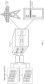
- FIG. 1 is a schematic diagram of an application scenario of a power conversion device according to this application.
- the power conversion device provided in this application may be an inverter shown in FIG. 1
- a terminal board and an electric energy conversion circuit provided in this application may be respectively a terminal board A and a DC/DC circuit shown in FIG. 1 .
- a protection switch provided in this application may be a contactor shown in FIG. 1 .
- the inverter includes the terminal board A, where input terminals a 1 , a 2 , a 3 , and a 4 of the inverter and a temperature sampling circuit as are disposed on the terminal board A.
- the input terminal a 1 and the input terminal a 2 of the inverter are respectively connected to two ends of a photovoltaic panel PV1 by using a contactor, the input terminal a 3 and the input terminal a 4 are respectively connected to two ends of a photovoltaic panel PV2 by using the contactor, and an output end is connected to an alternating current power grid or a household device.
- the inverter further includes the DC/DC circuit and an inverter circuit. An input end of the DC/DC circuit is connected to the four input terminals of the inverter, and an output end of the DC/DC circuit is connected to the output end of the inverter through the inverter circuit.
- the DC/DC circuit in the inverter After the inverter starts to run, the DC/DC circuit in the inverter performs direct current conversion on direct currents input by the photovoltaic panel PV1 and the photovoltaic panel PV2, and outputs, to the inverter circuit, direct currents obtained after the direct currents input by the input end are converted.
- the inverter circuit converts, into alternating currents, the direct currents obtained after the direct currents input by the input end are converted, and outputs the alternating currents from the output end, to supply power to various types of power-consuming equipment such as the alternating current power grid or an alternating current load (such as the household device).
- the inverter collects, by using the temperature sampling circuit a 5 , a temperature parameter of at least one input terminal of the four input terminals of the inverter, and when the temperature parameter of the at least one input terminal is greater than a temperature parameter threshold, which indicates that an input terminal with an excessively high temperature exists in the four input terminals of the inverter, the inverter controls the contactor to disconnect, and cuts off in time power supply loops where the four input terminals are located, that is, power supply loops of the photovoltaic panels PV1 and PV2. This implements overtemperature protection for the foregoing four input terminals, and protects the inverter.
- a sampling delay can be effectively avoided because the temperature sampling circuit as beside the input terminal can directly sample and conduct the temperature parameter of the input terminal in real time, and the inverter can be ensured to obtain the temperature of the input terminal of the inverter in time, so that overtemperature protection can be implemented on the input terminal of the inverter in time when the temperature of the input terminal of the inverter is excessively high, thereby ensuring reliable running of the input terminal.
- Examples of application scenarios of the power conversion device provided in this application are only illustrated above, but are not exhaustive. The application scenarios are not limited in this application.
- FIG. 2a is a schematic diagram of a structure of a power conversion device according to this application.
- the power conversion device 1 includes a terminal board 11, an electric energy conversion circuit 12, and a controller 13.
- a first terminal that is, an input terminal in 1
- a first temperature sampling circuit that is, a temperature sampling circuit 151
- the temperature sampling circuit 151 is configured to collect a temperature parameter of the input terminal in 1 .
- the input terminal in 1 of the power conversion device 1 is connected to a direct current power supply 101 by using a protection switch 141, and two output terminals out 11 and out 12 of the power conversion device 1 are connected to loads.
- An input end of the electric energy conversion circuit 12 is connected to the input terminal in 1 of the power conversion device 1, and two output ends are separately connected to the two output ends out 11 and out 12 of the power conversion device 1.
- the electric energy conversion circuit 12 includes a DC/DC circuit or an inverter circuit. It should be noted that, when the electric energy conversion circuit 12 is the DC/DC circuit, the power conversion device 1 is a DC/DC converter; when the electric energy conversion circuit 12 is the DC/DC circuit and the power conversion device 1 further includes an inverter circuit (located between the output end of the electric energy conversion circuit 12 and the output end of the power conversion device 1), the power conversion device 1 is an inverter; or when the electric energy conversion circuit 12 is the inverter circuit, the power conversion device 1 is an inverter.
- the direct current power supply 101 includes a photovoltaic panel, an energy storage battery, or a fuel cell, and the protection switch 14 includes a power transistor, a relay, or a contactor.
- the power transistor may be a metal-oxide-semiconductor field-effect transistor (metal-oxide-semiconductor field-effect transistor, MOSFET), an insulated gate bipolar transistor (Insulated Gate Bipolar Transistor, IGBT), a gallium nitride (Gallium Nitride, GaN) transistor, or the like.
- MOSFET metal-oxide-semiconductor field-effect transistor
- IGBT Insulated Gate Bipolar Transistor
- GaN gallium nitride
- the protection switch 141 may also be located inside the power conversion device 1. For details, refer to a power conversion device 1 shown in FIG. 2b . As shown in FIG. 2b , the protection switch 141 is disposed between the input terminal in 1 and the input end of the electric energy conversion circuit 12.
- the temperature sampling circuit 151 starts to collect a temperature parameter of the input terminal in 1 in real time.
- the controller 13 obtains the temperature parameter of the input terminal in 1 by using the temperature sampling circuit 151, and when the temperature parameter of the input terminal in 1 is greater than a temperature parameter threshold, which indicates that a temperature of the input terminal in 1 is excessively high, controls the protection switch 141 to be turned off, and disconnects in time a power supply loop in which the input terminal in 1 is located. This protects the input terminal in 1 , and further protects the power conversion device 1.
- a sampling delay can be effectively avoided because the temperature sampling circuit 151 beside the input terminal in 1 directly samples the temperature parameter of the input terminal in 1 , and the power conversion device 1 can be ensured to obtain the temperature of the input terminal in 1 in time, so that overtemperature protection can be implemented on the input terminal in 1 in time when the temperature of the input terminal in 1 is excessively high, thereby ensuring reliable running of the input terminal in 1 .
- a sampling manner in which the temperature sampling circuit 151 beside the input terminal in 1 directly collects the temperature parameter of the input terminal in 1 can also reduce an error of the collected temperature parameter, and improve control precision when the power conversion device 1 protects the input terminal of the power conversion device 1.
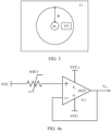
- a distance between the temperature sampling circuit 151 and the input terminal in 1 is less than a preset value R.
- the temperature sampling circuit 151 is located in a circular area whose radius is the preset value R shown in FIG. 3 .
- the preset value R only needs to ensure that the first temperature sampling circuit 151 can collect a correct temperature parameter of the input terminal in 1 .
- a specific value of the preset value R is not limited in this application.
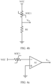
- FIG. 4a is a schematic diagram of a structure of a temperature sampling circuit according to this application.
- the temperature sampling circuit 151 includes a first thermistor NTC1 and a voltage follower U1.
- One end of the first thermistor NTC1 is connected to a first reference power supply VCC
- the other end of the first thermistor NTC1 is connected to a positive input end of the voltage follower U1
- a negative input end of the voltage follower U1 is connected to an output end of the voltage follower U1.
- the first reference power supply VCC is a 5 V direct current power supply.
- the first thermistor NTC1 in the temperature sampling circuit 151 converts a temperature of the input terminal in 1 into a voltage value V NTC1 , and inputs a voltage value VCC-V NTC1 into the voltage follower U1.
- the voltage follower U1 outputs the voltage value input by the positive input end of the voltage follower U1 to obtain a temperature parameter of the input terminal in 1 , that is, an output voltage V U1 of the voltage follower U1 is equal to VCC-V NTC1 .
- the controller 13 obtains the output voltage V U1 of the voltage follower U1 by using the temperature sampling circuit 151, and when the output voltage V U1 of the voltage follower U1 is greater than a temperature parameter threshold (that is, a first voltage threshold), which indicates that the temperature of the input terminal in 1 is excessively high, controls the protection switch 141 to be turned off, and disconnects in time a power supply loop in which the input terminal in 1 is located. This protects the input terminal in 1 , and further protects the power conversion device 1.
- a temperature parameter threshold that is, a first voltage threshold
- the controller 13 further collects a terminal current of the input terminal in 1 by using the current sampling circuit, and when the output voltage V U1 of the voltage follower U1 is greater than the first voltage threshold and the terminal current of the input terminal in 1 is greater than a current threshold, which indicates that the temperature of the input terminal in 1 is excessively high, controls the protection switch 141 to be turned off. It may be understood that, a terminal current determining condition manner is added to ensure accuracy of triggering the protection switch 141, avoid a wrong operation, and further improve control precision when the power conversion device 1 protects the input terminal of the power conversion device 1.
- the temperature sampling circuit 151 in FIG. 4a may further include a single-pole eight-throw switch.
- the single-pole eight-throw switch is configured to control whether the temperature sampling circuit 151 can obtain the temperature parameter of the input terminal corresponding to the temperature sampling circuit 151.
- the other end of the first thermistor NTC1 is connected to the positive input end of the voltage follower U1 by using the single-pole eight-throw switch. It may be understood that, a single-pole eight-throw switch manner is added to ensure that the temperature sampling circuit 151 works only when the power conversion device 1 needs to obtain the temperature parameter of the input terminal, and reduce power consumption of the power conversion device 1.
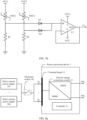
- FIG. 4b is a schematic diagram of another structure of a temperature sampling circuit according to this application.
- the temperature sampling circuit 151 includes a first thermistor NTC1 and a first voltage divider resistor R1.
- One end of the first thermistor NTC1 is connected to the first reference power supply VCC, and the other end of the first thermistor NTC1 is connected to the reference ground by using the first voltage divider resistor R1.
- the first reference power supply VCC is a 5 V direct current power supply.
- the controller 13 obtains the voltage V R1 of the first voltage divider resistor R1 by using the temperature sampling circuit 151, and when the voltage V R1 of the first voltage divider resistor R1 is greater than a temperature parameter threshold (that is, a second voltage threshold), which indicates that the temperature of the input terminal in 1 is excessively high, controls the protection switch 141 to be turned off, and disconnects in time a power supply loop in which the input terminal in 1 is located. This protects the input terminal in 1 , and further protects the power conversion device 1.
- a temperature parameter threshold that is, a second voltage threshold
- the controller 13 further collects a terminal current of the input terminal in 1 by using the current sampling circuit, and when the voltage V R1 of the first voltage divider resistor R1 is greater than the second voltage threshold and the terminal current of the input terminal in 1 is greater than a current threshold, which indicates that the temperature of the input terminal in 1 is excessively high, controls the protection switch 141 to be turned off. It may be understood that, a terminal current determining condition manner is added to ensure accuracy of triggering the protection switch 141, avoid a wrong operation, and further improve control precision when the power conversion device 1 protects the input terminal of the power conversion device 1.
- the temperature sampling circuit 151 in FIG. 4b may further include a single-pole eight-throw switch.
- the single-pole eight-throw switch is configured to control whether the temperature sampling circuit 151 can obtain the temperature parameter of the input terminal corresponding to the temperature sampling circuit 151.
- the single-pole eight-throw switch may be disposed between the first thermistor NTC1 and the first voltage divider resistor R1. It may be understood that, a single-pole eight-throw switch manner is added to ensure that the temperature sampling circuit 151 works only when the power conversion device 1 needs to obtain the temperature parameter of the input terminal, and reduce power consumption of the power conversion device 1.
- the first thermistor NTC1 in the temperature sampling circuit 151 converts a temperature of the input terminal in 1 into a voltage value V NTC1 , and inputs a voltage value VCC-V NTC1 into the inverting amplifier A1.
- the inverting amplifier A1 performs inverting amplification on the voltage value input by the inverting input end of the inverting amplifier A1 to obtain a temperature parameter of the input terminal in 1 , that is, an output voltage V A1 of the inverting amplifier A1 is equal to ⁇ (VCC-V NTC1 ), where ⁇ is an amplification coefficient of the inverting amplifier A1, and ⁇ 0.
- the controller 13 obtains the output voltage V A1 of the inverting amplifier A1 by using the temperature sampling circuit 151, and when the output voltage V A1 of the inverting amplifier A1 is greater than a temperature parameter threshold (that is, a third voltage threshold), which indicates that the temperature of the input terminal in 1 is excessively high, controls the protection switch 141 to be turned off, and disconnects in time a power supply loop in which the input terminal in 1 is located. This protects the input terminal in 1 , and further protects the power conversion device 1.
- a temperature parameter threshold that is, a third voltage threshold
- the controller 13 further collects a terminal current of the input terminal in 1 by using the current sampling circuit, and when the output voltage V A1 of the inverting amplifier A1 is greater than the third voltage threshold and the terminal current of the input terminal in 1 is greater than a current threshold, which indicates that the temperature of the input terminal in 1 is excessively high, controls the protection switch 141 to be turned off. It may be understood that, a terminal current determining condition manner is added to ensure accuracy of triggering the protection switch 141, avoid a wrong operation, and further improve control precision when the power conversion device 1 protects the input terminal of the power conversion device 1.
- the temperature sampling circuit 151 in FIG. 4c may further include a single-pole eight-throw switch.
- the single-pole eight-throw switch is configured to control whether the temperature sampling circuit 151 can obtain the temperature parameter of the input terminal corresponding to the temperature sampling circuit 151.
- the other end of the first thermistor NTC1 is connected to the non-inverting input end of the inverting amplifier A1 by using the single-pole eight-throw switch. It may be understood that, a single-pole eight-throw switch manner is added to ensure that the temperature sampling circuit 151 works only when the power conversion device 1 needs to obtain the temperature parameter of the input terminal, and reduce power consumption of the power conversion device 1.
- the first thermistor NTC1 in the temperature sampling circuit 151 is a unique thermal sensitive element (that is, an element that converts a temperature into an electrical signal). In other words, temperature sampling on the input terminal in 1 may be completed by using only the first thermistor NTC1. For diversity of the temperature sampling circuit 151, different elements may also be connected to the first thermistor NTC1. When elements connected to the first thermistor NTC1 are different, the temperature parameter of the input terminal in 1 may change with the element connected to the first thermistor NTC1. Therefore, the temperature sampling circuit 151 has various structures, and correspondingly, the input terminal in 1 has various overtemperature determining conditions, and has high flexibility.
- An element connected to the first thermistor NTC1 is not limited in this application.
- the temperature sampling circuits 151 in this application all directly conduct the temperature of the input terminal by using the thermistor. Because a temperature measurement range of the thermistor reaches -40°C to +150°C, the temperature sampling circuit 151 has a wide measurement range, and is highly applicable.
- a sampling delay can be effectively avoided because the temperature sampling circuit 151 beside the input terminal in 1 directly samples the temperature parameter of the input terminal in 1 , and the power conversion device 1 can be ensured to obtain the temperature of the input terminal in 1 in time, so that overtemperature protection can be implemented on the input terminal in 1 in time when the temperature of the input terminal in 1 is excessively high, thereby ensuring reliable running of the input terminal in 1 .
- a sampling manner in which the temperature sampling circuit 151 beside the input terminal in 1 directly collects the temperature parameter of the input terminal in 1 can also reduce an error of the collected temperature parameter, and improve control precision when the power conversion device 1 protects the input terminal of the power conversion device 1.
- the temperature sampling circuit 151 has a simple structure, is easy to control, is easy to operate, and can further improve stability of the power conversion device 1.
- the temperature sampling circuit 151 has various structures and high flexibility, and can also improve structure diversity of the power conversion device 1.
- FIG. 5a is a schematic diagram of still another structure of a power conversion device according to this application.
- a power conversion device 1 includes a terminal board 11, an electric energy conversion circuit 12, and a controller 13.
- n terminals that is, an input terminal in 1 , ..., an input terminal in n
- a first temperature sampling circuit that is, a temperature sampling circuit 151
- the temperature sampling circuit 151 is configured to collect a temperature parameter of at least one of the n input terminals.
- the input terminal in 1 of the power conversion device 1 is connected to a direct current power supply 101 by using a protection switch 141 corresponding to the power conversion device 1, ..., and the input terminal in n is connected to a direct current power supply 10n by using a protection switch 14n corresponding to the input terminal in n .
- Two output ends outi 1 and out 12 of the power conversion device 1 are connected to loads.
- An input end of the electric energy conversion circuit 12 is connected to the input terminal in 1 of the power conversion device 1, and two output ends are separately connected to the two output ends out 11 and out 12 of the power conversion device 1.
- the protection switch 141, ..., and the protection switch 14n may also be located inside the power conversion device 1.
- the input terminal in 1 is connected to the input end of the electric energy conversion circuit 12 by using the protection switch 141 corresponding to the input terminal in 1 , ..., and the input terminal in n is connected to the input end of the electric energy conversion circuit 12 by using the protection switch 14n corresponding to the input terminal in n .
- a physical diagram of the terminal board 11 is the terminal board 11 in FIG. 6
- a physical diagram of the input terminal is welded PV terminals a 1 or a 2 in FIG. 6 .
- the controller 13 obtains a temperature parameter, that is, a first temperature parameter, by using the temperature sampling circuit 151, where the first temperature parameter may be understood as a temperature parameter of each of the n input terminals, and namely, temperature parameters of the n terminals, and when the first temperature parameter is greater than a temperature parameter threshold, which indicates that there is a terminal with an excessively high temperature in the n input terminals, controls the protection switch 141, ..., and the protection switch 14n to be all turned off, and disconnects in time power supply loops in which the n input terminals are located.
- a temperature parameter that is, a first temperature parameter
- FIG. 7a is a schematic diagram of yet another structure of a temperature sampling circuit according to this application.
- the temperature sampling circuit 151 includes a first thermistor NTC1, a second thermistor NTC2, and a voltage follower U1.
- One end of the first thermistor NTC1 is connected to a first reference power supply VCC1
- one end of the second thermistor NTC2 is connected to a second reference power supply VCC2
- both the other end of the first thermistor NTC1 and the other end of the second thermistor NTC2 are connected to a positive input end of the voltage follower U1
- a negative input end of the voltage follower U1 is connected to an output end of the voltage follower U1.
- the first thermistor NTC1 is configured to detect a temperature of the input terminal in 1
- the second thermistor NTC2 is configured to detect a temperature of the input terminal in 2 .
- both the first reference power supply VCC1 and the second reference power supply VCC2 are 5 V direct current power supplies.
- the first temperature parameter is a temperature parameter of the input terminal in 1 , and is also a temperature parameter of the input terminal in 2 , that is, an output voltage V U1 of the voltage follower U1 is equal to VCC-V NTC1 , or V U1 is equal to VCC-V NTC2 .
- the controller 13 obtains the output voltage V U1 of the voltage follower U1 by using the temperature sampling circuit 151, and when the output voltage V U1 of the voltage follower U1 is greater than a temperature parameter threshold (that is, a first voltage threshold), which indicates that there is an input terminal with an excessively high temperature in the input terminal in 1 and the input terminal in 2 , controls both a protection switch 141 corresponding to the input terminal in 1 and a protection switch 142 corresponding to the input terminal in 2 to be turned off, and disconnects in time power supply loops where the input terminal in 1 and the input terminal in 2 are located. This protects the input terminal in 1 and the input terminal in 2 , and further protects the power conversion device 1.
- a temperature parameter threshold that is, a first voltage threshold
- One end of the first thermistor NTC1 is connected to a first reference power supply VCC1
- one end of the second thermistor NTC2 is connected to a second reference power supply VCC2
- the other end of the first thermistor NTC1 is connected to one end of the first voltage divider resistor R1 and an anode of the first diode D1
- the other end of the first voltage divider resistor R1 is connected to the reference ground
- a cathode of the first diode D1 is connected to a positive input end of the voltage follower U1.
- the other end of the second thermistor NTC2 is connected to one end of the second voltage divider resistor R2 and an anode of the second diode D2, the other end of the second voltage divider resistor R2 is connected to the reference ground, a cathode of the second diode D2 is connected to the positive input end of the voltage follower U1, and a negative input end of the voltage follower U1 is connected to an output end of the voltage follower U1.
- the first thermistor NTC1 is configured to detect a temperature of the input terminal in 1
- the second thermistor NTC2 is configured to detect a temperature of the input terminal in 2 .
- both the first reference power supply VCC1 and the second reference power supply VCC2 are 5 V direct current power supplies.
- the first thermistor NTC1 in the temperature sampling circuit 151 converts the temperature of the input terminal in 1 into a voltage value V NTC1 , and inputs a voltage value VCC-V NTC1 into the anode of the first diode D1; and the second thermistor NTC2 converts the temperature of the input terminal in 2 into a voltage value V NTC2 , and inputs a voltage value VCC-V NTC2 into the anode of the second diode D2.
- the positive input end of the voltage follower U1 receives the VCC-V NTC1 or the VCC-V NTC2 , and outputs the voltage value (that is, the VCC-V NTC1 or the VCC-V NTC2 ) input by the positive input end of the voltage follower U1, to obtain a first temperature parameter.
- the first temperature parameter is a temperature parameter of the input terminal in 1 , and is also a temperature parameter of the input terminal in 2 , that is, an output voltage V U1 of the voltage follower U1 is equal to VCC-V NTC1 , or V U1 is equal to VCC-V NTC2 .
- the controller 13 further collects terminal currents of the input terminal in 1 and the input terminal in 2 by using a current sampling circuit, to obtain two terminal currents, and when the output voltage V U1 of the voltage follower U1 is greater than the first voltage threshold and there is a terminal current greater than the current threshold in the two terminal currents, which indicates that there is the input terminal with the excessively high temperature in the input terminal in 1 and the input terminal in 2 , controls the protection switch 141 and the protection switch 142 to be turned off.
- a terminal current determining condition manner is added to ensure accuracy of triggering the protection switch 141 and the protection switch 142, avoid a wrong operation, and further improve control precision when the power conversion device 1 protects the input terminal of the power conversion device 1.
- a sampling delay can be effectively avoided because one temperature sampling circuit 151 beside the plurality of input terminals directly samples temperature parameters of the plurality of input terminals, and the power conversion device 1 can be ensured to obtain temperatures of the plurality of input terminals whose temperatures are to be measured in time, so that overtemperature protection can be implemented on the input terminals of the power conversion device 1 in time when of the input terminals whose temperatures are to be measured are excessively high, thereby ensuring reliable running of the input terminals of the power conversion device 1.
- a sampling manner in which the temperature sampling circuit 151 beside the plurality of input terminals directly collects temperature parameters of the plurality of input terminals can also reduce an error of the collected temperature parameters, and improve control precision when the power conversion device 1 protects the input terminal of the power conversion device 1.
- the temperature sampling circuit 151 has a simple structure, is easy to control, is easy to operate, and can further improve stability of the power conversion device 1.
- the temperature sampling circuit 151 has various structures and high flexibility, and can also improve structure diversity of the power conversion device 1.
- the plurality of input terminals may share one voltage follower U1 in the temperature sampling circuit 151 shown in FIG. 7a and FIG. 7b . This can reduce a volume and costs of the temperature sampling circuit 151, and reduce a volume and costs of the power conversion device 1.
- n input terminals when n input terminals are disposed on the terminal board 11, m temperature sampling circuits (that is, a temperature sampling circuit 151, a temperature sampling circuit 152, ..., and a temperature sampling circuit 15m) corresponding to the n input terminals are also disposed on the terminal board 11, where 2 ⁇ m ⁇ n.
- the n input terminals include m groups of input terminals, that is, a first group of input terminals, a second group of input terminals, ..., and a m th group of input terminals.
- a quantity of terminals included in each of the m groups of input terminals is greater than or equal to 1, and the quantity of terminals included in each group of input terminals may be the same or may be different.
- Each temperature sampling circuit is configured to collect a temperature parameter of a group of input terminals corresponding to each temperature sampling circuit.
- the temperature parameter that is of the group of input terminals corresponding to the temperature sampling circuit and that is collected by the temperature sampling circuit is a value, and the value may be understood as a temperature parameter of each input terminal in the group of input terminals corresponding to the temperature sampling circuit.
- a distance between each temperature sampling circuit and a group of input terminals corresponding to each temperature sampling circuit is less than a preset value R.
- the m temperature sampling circuits collect temperature parameters of respective corresponding group of terminals, to obtain m temperature parameters.
- the controller 13 obtains the m temperature parameters by using the m temperature sampling circuits, and determines, based on the m temperature parameters, that a target group input terminal whose temperature parameter is greater than a temperature parameter threshold exists in the m groups of input terminals, which indicates that the input terminal with excessively high temperature exists in the target group input terminal, the controller 13 controls protection switches corresponding to the target group input terminals to be all turned off.
- the controller 13 controls both a protection switch corresponding to the first group of input terminals and a protection switch corresponding to the second group of input terminals to be turned off.
- the four terminals include a first group of input terminals, a second group of input terminals, a third group of input terminals, and a fourth group of input terminals, and a quantity of terminals included in each of the foregoing four groups of input terminals is 1.
- the controller 13 obtains four temperature parameters by using the foregoing four temperature sampling circuits, and when an input terminal whose temperature parameter is greater than a temperature parameter threshold exists in the four input terminals, the controller 13 controls a protection switch corresponding to the input terminal whose temperature parameter is greater than the temperature parameter threshold to be turned off.
- the power conversion device 1 when finding that a group of input terminals with an excessively high temperature exists in the n input terminals of the power conversion device 1, the power conversion device 1 directly turns ff all protection switches corresponding to the group of input terminals with the excessively high temperature. This can improve security of the power conversion device 1.
- a manner of disconnecting only the input terminal with the excessively high temperature can ensure that other input terminals in the power conversion device 1 except the input terminal with excessively high temperature can still work normally. This can ensure that the power conversion device 1 can still normally supply power to the load, and improve stability of the power conversion device 1.
- the temperature sampling circuit corresponding to each terminal may be any one of the temperature sampling circuits 151 shown in FIG. 4a to FIG. 4c .
- the temperature parameter herein may be any one of the output voltage of the voltage follower U1, a voltage of the first voltage divider resistor R1, and an output voltage of an inverting amplifier A1.
- the temperature sampling circuit corresponding to the plurality of terminals may be any one of the temperature sampling circuits 151 shown in FIG. 7a and FIG. 7b .
- the temperature parameter herein may be the output voltage of the voltage follower U1.
- a sampling delay can be effectively avoided because the temperature sampling circuit 151 beside the input terminal whose temperature is to be measured directly samples the temperature parameter of the input terminal whose temperature is to be measured, and the power conversion device 1 can be ensured to obtain the temperature of the input terminal whose temperature is to be measured in time, so that overtemperature protection can be implemented on the input terminal in time when the temperature of the input terminal whose temperature is to be measured is excessively high, thereby ensuring reliable running of the input terminal of the power conversion device 1.
- FIG. 8a is a schematic diagram of still yet another structure of a power conversion device according to this application.
- a power conversion device 1 includes a terminal board 11, an electric energy conversion circuit 12, and a controller 13.
- n terminals that is, an input terminal in 1 , ..., an input terminal in n
- the temperature sampling circuit 151 is configured to collect a temperature parameter of at least one of the n input terminals.
- the n input terminals (that is, the input terminals in 1 , ..., and the input terminals in n ) of the power conversion device 1 are all connected to n direct current power supplies (that is, a direct current power supply 101, ..., and a direct current power supply 10n) by using a protection switch 141.
- n direct current power supplies that is, a direct current power supply 101, ..., and a direct current power supply 10n
- Two output ends outi 1 and out 12 of the power conversion device 1 are connected to loads.
- An input end of the electric energy conversion circuit 12 is connected to the n input terminals of the power conversion device 1, and two output ends are separately connected to the two output ends out 11 and out 12 of the power conversion device 1.
- the protection switch 141 may also be located inside the power conversion device 1.
- the input terminals in 1 , ..., and the input terminal in n are all connected to the input end of the electric energy conversion circuit 12 by using the protection switch 141.
- the controller 13 obtains a temperature parameter, that is, a first temperature parameter, by using the temperature sampling circuit 151, where the first temperature parameter may be understood as a temperature parameter of each of the n input terminals, and when the first temperature parameter is greater than a temperature parameter threshold, which indicates that there is a terminal with an excessively high temperature in the n input terminals, controls the protection switch 141 to be turned off, and disconnects in time power supply loops in which the n input terminals are located.
- a temperature parameter that is, a first temperature parameter
- the controller 13 further collects a terminal current of each of the n input terminals by using the current sampling circuit, to obtain n terminal currents, and when the first temperature parameter is greater than the temperature parameter threshold, and a first input terminal whose terminal current is greater than the current threshold exists in the n input terminals, which indicates that there is the terminal with the excessively high temperature in the n input terminals and the input terminal with the excessively high temperature is the first input terminal, controls a protection switch 141 to be turned off. It may be understood that, a terminal current determining condition manner is added to ensure accuracy of triggering the protection switch 141, avoid a wrong operation, and further improve control precision when the power conversion device 1 protects the input terminal of the power conversion device 1.
- the temperature sampling circuit 151 corresponds to the plurality of input terminals, for a specific structure of the temperature sampling circuit 151, refer to the temperature sampling circuit 151 shown in FIG. 7a and FIG. 7b . Details are not described herein again.
- n input terminals when n input terminals are disposed on the terminal board 11, m temperature sampling circuits (that is, a temperature sampling circuit 151, a temperature sampling circuit 152, ..., and a temperature sampling circuit 15m) corresponding to the n input terminals are also disposed on the terminal board 11, where 2 ⁇ m ⁇ n.
- the n input terminals include m groups of input terminals, that is, a first group of input terminals, a second group of input terminals, ..., and a m th group of input terminals.
- a quantity of terminals included in each of the m groups of input terminals is greater than or equal to 1, and the quantity of terminals included in each group of input terminals may be the same or may be different.
- Each temperature sampling circuit is configured to collect a temperature parameter of a group of input terminals corresponding to each temperature sampling circuit.
- the temperature parameter that is of the group of input terminals corresponding to the temperature sampling circuit and that is collected by the temperature sampling circuit is a value, and the value may be understood as a temperature parameter of each input terminal in the group of input terminals corresponding to the temperature sampling circuit.
- a distance between each temperature sampling circuit and a group of input terminals corresponding to each temperature sampling circuit is less than a preset value R.
- the m temperature sampling circuits collect temperature parameters of respective corresponding group of input terminals, to obtain m temperature parameters.
- the controller 13 obtains the m temperature parameters by using the m temperature sampling circuits, and determines, based on the m temperature parameters, that a target group input terminal whose temperature parameter is greater than a temperature parameter threshold exists in the m groups of input terminals, which indicates that the input terminal with excessively high temperature exists in the target group input terminal, the controller 13 controls the protection switch 141 to be turned off. It may be understood that, when the power conversion device 1 finds that the terminal with the excessively high temperature exists in the input terminals of the power conversion device 1, the power conversion device 1 directly disconnects the power supply loops where the plurality of input terminals are located. This can improve security of the power conversion device 1.
- the controller 13 further obtains a terminal current of each of the n input terminals by using the current sampling circuit, to obtain the n terminal currents, and when a target group input terminal whose temperature parameter is greater than the temperature parameter threshold exists in the m groups of input terminals, and an input terminal whose terminal current is greater than a current threshold exists in the target group input terminal, which indicates that a temperature of the target group input terminal is excessively high, controls the protection switch 141 to be turned off. It may be understood that, a terminal current determining condition manner is added to ensure accuracy of triggering the protection switch 141, avoid a wrong operation, and further improve control precision when the power conversion device 1 protects the input terminal of the power conversion device 1.
- the temperature sampling circuit corresponding to each terminal may be any one of the temperature sampling circuits 151 shown in FIG. 4a to FIG. 4c .
- the temperature parameter herein may be any one of the output voltage of the voltage follower U1, a voltage of the first voltage divider resistor R1, and an output voltage of an inverting amplifier A1.
- the temperature sampling circuit corresponding to the plurality of terminals may be any one of the temperature sampling circuits 151 shown in FIG. 7a and FIG. 7b .
- the temperature parameter herein may be the output voltage of the voltage follower U1.
- a sampling delay can be effectively avoided because the temperature sampling circuit 151 beside input terminals whose temperatures are to be measured directly samples all temperature parameters of the input terminals whose temperatures are to be measured, and the power conversion device 1 can be ensured to obtain the temperature of the input terminal whose temperature is to be measured in time, so that overtemperature protection can be implemented on the input terminal in time when the temperature of the input terminal whose temperature is to be measured is excessively high, thereby ensuring reliable running of the input terminal of the power conversion device 1.
- a sampling manner in which the temperature sampling circuit 151 beside the input terminal whose temperature is to be measured directly collects the temperature parameter of the input terminal whose temperature is to be measured can also reduce an error of the collected temperature parameter, and improve control precision when the power conversion device protects the input terminal of the power conversion device 1.
- the temperature sampling circuit 151 has a simple structure, is easy to control, is easy to operate, and can further improve stability of the power conversion device 1.
- the temperature sampling circuit 151 has various structures and high flexibility, and can also improve structure diversity of the power conversion device 1.
- power supply loops of a plurality of input terminals share a same protection switch. This can effectively reduce costs of the power conversion device 1 or a power supply system in which the power conversion device 1 is located.
- FIG. 9 is a schematic flowchart of a protection method for a power conversion device according to this application.
- the protection method for the power conversion device provided in embodiments of this application is applicable to the power conversion device 1 shown in FIG. 2a to FIG. 8b .
- the protection method for the power conversion device may include the following steps: S101: Obtain a temperature parameter of a first terminal by using a first temperature sampling circuit.
- the first temperature sampling circuit starts to collect the temperature parameter of the first terminal.
- the power conversion device obtains the temperature parameter of the first terminal by using the first temperature sampling circuit.
- n terminals including the first terminal
- one first temperature sampling circuit corresponding to the n terminals are disposed on a terminal board of the power conversion device
- the first temperature sampling circuit starts to collect a first temperature parameter, that is, a temperature parameter of each of the n input terminals.
- the power conversion device obtains the first temperature parameter by using the first temperature sampling circuit.
- n is an integer greater than 1.
- n terminals including the first terminal
- m temperature sampling circuits including the first temperature sampling circuit
- the power conversion device works, the m temperature sampling circuits collect temperature parameters of respective corresponding groups of terminals, to obtain m temperature parameters.
- the power conversion device obtains the m temperature parameters by using the m temperature sampling circuits.
- n is an integer greater than 1, and 2 ⁇ m ⁇ n.
- a quantity of terminals included in each of m groups of input terminals is greater than or equal to 1, and the quantity of terminals included in each group of input terminals may be the same or may be different.
- the power conversion device when the temperature parameter of the first terminal is greater than the temperature parameter threshold, the power conversion device controls a protection switch connected to the first terminal to be turned off.
- the power conversion device controls a protection switch connected to the first terminal to be turned off.
- the power conversion device when the first temperature parameter is greater than the temperature parameter threshold, controls a protection switch corresponding to a plurality of terminals to be turned off, or controls a plurality of protection switches that one-to-one correspond to a plurality of terminals to be all turned off.
- the power conversion device controls a protection switch corresponding to the first terminal to be turned off.
- the power conversion device controls protection switches corresponding to the first group of terminals to be turned off.
- the power conversion device controls a protection switch corresponding to the first terminal to be turned off.
- a sampling delay can be effectively avoided because a temperature sampling circuit beside input terminals whose temperatures are to be measured directly samples all temperature parameters of the input terminals whose temperatures are to be measured, and the power conversion device can be ensured to obtain the temperature of the input terminal whose temperature is to be measured in time, so that overtemperature protection can be implemented on the input terminal in time when the temperature of the input terminal whose temperature is to be measured is excessively high, thereby ensuring reliable running of the input terminal of the power conversion device.
- a sampling manner in which the temperature sampling circuit beside the input terminal whose temperature is to be measured directly collects the temperature parameter of the input terminal whose temperature is to be measured can also reduce an error of the collected temperature parameter, improve control precision when the power conversion device protects the input terminal of the power conversion device, and is highly applicable.
Landscapes
- Engineering & Computer Science (AREA)
- Power Engineering (AREA)
- Protection Of Static Devices (AREA)
- Dc-Dc Converters (AREA)
Abstract
Description
- This application claims priority to
Chinese Patent Application No. 202210976648.7, filed with the China National Intellectual Property Administration on August 15, 2022 - This application relates to the field of power supply technologies, and in particular, to a power conversion device and a protection method for the power conversion device.
- A photovoltaic inverter usually uses a photovoltaic terminal as an input end of the photovoltaic inverter. The photovoltaic terminal transmits a current of a photovoltaic battery to the inside of the inverter through a reliable electrical connection, and implements current inversion, so that electric energy can be used by a terminal user or be used in a power grid. As an important component of the photovoltaic inverter, the photovoltaic terminal may be damaged when a temperature of the photovoltaic terminal is excessively high, and then the inverter is damaged. Therefore, it is particularly important to ensure reliable running of the photovoltaic terminal.
- This application provides a power conversion device and a protection method for the power conversion device, so that a temperature of a terminal whose temperature is to be measured can be obtained in time, and overtemperature protection can be implemented on the terminal in time when the temperature of the terminal whose temperature is to be measured is excessively high, thereby ensuring reliable running of the terminal of the power conversion device.
- According to a first aspect, this application provides a power conversion device. The power conversion device includes a terminal board, an electric energy conversion circuit, and a controller, a first terminal and a first temperature sampling circuit are disposed on the terminal board. The first terminal is connected to a direct current power supply or the electric energy conversion circuit by using a protection switch. The first temperature sampling circuit is configured to collect a temperature parameter of the first terminal. The controller obtains the temperature parameter of the first terminal, and when the temperature parameter of the first terminal is greater than a temperature parameter threshold, which indicates that a temperature of the first terminal is excessively high, controls the protection switch to be turned off, and disconnects in time a power supply loop in which the first terminal is located. This protects the first terminal, and further protects the power conversion device. A sampling delay can be effectively avoided because the first temperature sampling circuit beside the first terminal directly samples the temperature parameter of the first terminal, and the power conversion device can be ensured to obtain the temperature of the terminal whose temperature is to be measured in time, so that overtemperature protection can be implemented on the terminal in time when the temperature of the terminal whose temperature is to be measured is excessively high, thereby ensuring reliable running of the terminal. In addition, a sampling manner in which the first temperature sampling circuit beside the first terminal directly obtains the temperature parameter of the first terminal can also reduce an error of the collected temperature parameter, and improve control precision when the power conversion device protects the input terminal of the power conversion device.
- With reference to the first aspect, in a first possible implementation, the controller further obtains a terminal current of the first terminal, and controls, when the temperature parameter of the first terminal is greater than the temperature parameter threshold, and the terminal current of the first terminal is greater than a current threshold, the protection switch to be turned off. Further, a terminal current determining condition manner is added to ensure accuracy of triggering the protection switch, avoid a wrong operation, and further improve control precision when the power conversion device protects the input terminal of the power conversion device.
- With reference to the first aspect or the first possible implementation of the first aspect, in a second possible implementation, the first temperature sampling circuit includes a first thermistor, and the first thermistor is configured to detect the temperature parameter of the first terminal.
- With reference to the second possible implementation of the first aspect, in a third possible implementation, the first temperature sampling circuit further includes a voltage follower. One end of the first thermistor is connected to a first reference power supply, the other end of the first thermistor is connected to a first input end of the voltage follower, and a second input end of the voltage follower is connected to an output end of the voltage follower. The temperature parameter is an output voltage of the voltage follower. In this implementation, the first temperature sampling circuit is simple, easy to control, and highly operable. In addition, because the first temperature sampling circuit is simple, stability of the power conversion device can also be improved.
- With reference to the second possible implementation of the first aspect, in a fourth possible implementation, the first temperature sampling circuit further includes a first voltage divider resistor. One end of the first thermistor is connected to the first reference power supply, and the other end of the first thermistor is connected to the reference ground by using the first voltage divider resistor. The temperature parameter is a voltage of the first voltage divider resistor. In this implementation, the first temperature sampling circuit is simple, easy to control, and highly operable. In addition, because the first temperature sampling circuit is simple, stability of the power conversion device can also be improved.
- With reference to the second possible implementation of the first aspect, in a fifth possible implementation, the first temperature sampling circuit further includes an inverting amplifier. One end of the first thermistor is connected to the first reference power supply, the other end of the first thermistor is connected to an inverting input end of the inverting amplifier, and a non-inverting input end of the inverting amplifier is connected to the reference ground. The temperature parameter is an output voltage of the inverting amplifier. The first temperature sampling circuit has various structures, and correspondingly, the terminal has various overtemperature determining conditions, and has high flexibility.
- With reference to any one of the first aspect to the fifth possible implementation of the first aspect, in a sixth possible implementation, a distance between the first temperature sampling circuit and the first terminal is less than a preset value.
- With reference to the first aspect, in a seventh possible implementation, a plurality of terminals are disposed on the terminal board, the plurality of terminals include the first terminal, the plurality of terminals are connected to the direct current power supply or the electric energy conversion circuit by using a plurality of protection switches corresponding to the plurality of terminals, and the plurality of terminals one-to-one correspond to the plurality of protection switches. Distances between the first temperature sampling circuit and the plurality of terminals are all less than a preset value, and the first temperature sampling circuit is configured to collect a first temperature parameter. The controller obtains the first temperature parameter, and when the first temperature parameter is greater than the temperature parameter threshold, which indicates that there is a terminal with an excessively high temperature in the plurality of terminals, controls the plurality of protection switches to be all turned off, and disconnects in time power supply loops in which the plurality of input terminals are located. This protects the plurality of input terminals, and further protects the power conversion device. It may be understood that, when finding that there is the input terminal with the excessively high temperature in the plurality of input terminals, the power conversion device directly turns off all the plurality of protection switches corresponding to the plurality of input terminals. This can improve security of the power conversion device. In addition, the plurality of terminals share a same first temperature sampling circuit. This can effectively reduce costs and a volume of the first temperature sampling circuit disposed on the terminal board, and reduce costs and a volume of the power conversion device.
- With reference to the first aspect, in an eighth possible implementation, a plurality of terminals are disposed on the terminal board, the plurality of terminals include the first terminal, and the plurality of terminals are all connected to the direct current power supply or the electric energy conversion circuit by using the protection switch. Distances between the first temperature sampling circuit and the plurality of terminals are all less than a preset value, and the first temperature sampling circuit is configured to collect a first temperature parameter. The controller obtains the first temperature parameter, and controls, when the first temperature parameter is greater than the temperature parameter threshold, the protection switch to be turned off. It may be understood that the plurality of terminals share a same temperature sampling circuit and a same protection switch. This can effectively reduce costs and a volume of the power conversion device.
- With reference to first aspect, in a ninth possible implementation, a plurality of terminals and a plurality of temperature sampling circuits are disposed on the terminal board, the plurality of terminals include a first group of terminals and a second group of terminals, the first group of terminals includes the first terminal, and the plurality of temperature sampling circuits include the first temperature sampling circuit and a second temperature sampling circuit. The plurality of terminals are connected to the direct current power supply or the electric energy conversion circuit by using a plurality of protection switches corresponding to the plurality of terminals, and the plurality of terminals one-to-one correspond to the plurality of protection switches. The first temperature sampling circuit is configured to collect temperature parameters of the first group of terminals, and the second temperature sampling circuit is configured to collect temperature parameters of the second group of terminals. The controller obtains the temperature parameters of the first group of terminals and the temperature parameters of the second group of terminals, and controls, when a first group of terminals whose temperature parameters are greater than the temperature parameter threshold exists in the first group of terminals and the second group of terminals, which indicates that a terminal with an excessively high temperature exists in the first group of terminals, protection switches corresponding to the first group of terminals to be turned off. It may be understood that, when finding that a group of input terminals with the excessively high temperature exists in the plurality of input terminals of the power conversion device, the power conversion device directly turns off all protection switches corresponding to the group of input terminals with the excessively high temperature. This can improve security of the power conversion device.
- With reference to first aspect, in a tenth possible implementation, a plurality of terminals and a plurality of temperature sampling circuits are disposed on the terminal board, the plurality of terminals include a first group of terminals and a second group of terminals, the first group of terminals includes the first terminal, and the plurality of temperature sampling circuits include the first temperature sampling circuit and a second temperature sampling circuit. The plurality of terminals are connected to the direct current power supply or the electric energy conversion circuit by using the protection switch. The first temperature sampling circuit is configured to collect temperature parameters of the first group of terminals, and the second temperature sampling circuit is configured to collect temperature parameters of the second group of terminals. The controller obtains the temperature parameters of the first group of terminals and the temperature parameters of the second group of terminals, and controls, when a first group of terminals whose temperature parameters are greater than the temperature parameter threshold exists in the first group of terminals and the second group of terminals, the protection switch to be turned off. It may be understood that the plurality of terminals share a same protection switch. This can effectively reduce costs and a volume of the power conversion device or a power supply system in which the power conversion device is located.
- With reference to any one of the seventh possible implementation to the tenth possible implementation of the first aspect, in an eleventh possible implementation, the plurality of terminals include the first terminal and a second terminal, and the first temperature sampling circuit includes the voltage follower, a first thermistor, and a second thermistor. One end of the first thermistor is connected to the first reference power supply, one end of the second thermistor is connected to a second reference power supply, both the other end of the first thermistor and the other end of the second thermistor are connected to the first input end of the voltage follower, and the second input end of the voltage follower is connected to the output end of the voltage follower. The first thermistor is configured to detect the temperature parameter of the first terminal, and the second thermistor is configured to detect a temperature parameter of the second terminal. The temperature parameter is an output voltage of the voltage follower. The first terminal and the second terminal can share one voltage follower in the first temperature sampling circuit. This can reduce a volume and costs of the first temperature sampling circuit, and can reduce a volume and costs of the power conversion device.
- With reference to the eleventh possible implementation of the first aspect, in a twelfth possible implementation, the first temperature sampling circuit further includes a first diode, a first voltage divider resistor, a second diode, and a second voltage divider resistor. The other end of the first thermistor is separately connected to the first input end of the voltage follower and the reference ground by using the first diode and the first voltage divider resistor, and the other end of the second thermistor is separately connected to the first input end of the voltage follower and the reference ground by using the second diode and the second voltage divider resistor. The first temperature sampling circuit has various structures, so that the power conversion device has various structures and high flexibility.
- With reference to any one of the first aspect to the twelfth possible implementation of the first aspect, in a thirteenth possible implementation, the protection switch includes a power transistor, a relay, or a contactor.
- With reference to any one of the first aspect to the thirteenth possible implementation of the first aspect, in a fourteenth possible implementation, the power conversion device includes an inverter or a DC/DC converter.
- With reference to any one of the first aspect to the fourteenth possible implementation of the first aspect, in a fifteenth possible implementation, the direct current power supply includes a photovoltaic panel, an energy storage battery, or a fuel cell. It may be understood that the power conversion device provided in this application is applicable to a photovoltaic power supply scenario, an energy storage power supply scenario, and a fuel cell power supply scenario, and is highly applicable.
- According to a second aspect, this application provides a protection method for a power conversion device. The power conversion device includes a terminal board and an electric energy conversion circuit, a first terminal and a first temperature sampling circuit are disposed on the terminal board, and the first terminal is connected to a direct current power supply or the electric energy conversion circuit by using a protection switch. The method includes: The power conversion device obtains a temperature parameter of the first terminal by using a first temperature sampling circuit, and control, when the temperature parameter of the first terminal is greater than a temperature parameter threshold, a protection switch to be turned off.
- With reference to the second aspect, in a first possible implementation, the power conversion device further obtains a terminal current of the first terminal, and controls, when the temperature parameter of the first terminal is greater than the temperature parameter threshold, and the terminal current of the first terminal is greater than a current threshold, the protection switch to be turned off.
- With reference to the second aspect or the first possible implementation of the second aspect, in a second possible implementation, the first temperature sampling circuit includes a first thermistor, and the first thermistor is configured to detect the temperature parameter of the first terminal.
- With reference to the second possible implementation of the second aspect, in a third possible implementation, the first temperature sampling circuit further includes a voltage follower. One end of the first thermistor is connected to a first reference power supply, the other end of the first thermistor is connected to a first input end of the voltage follower, and a second input end of the voltage follower is connected to an output end of the voltage follower. The temperature parameter is an output voltage of the voltage follower.
- With reference to the second possible implementation of the second aspect, in a fourth possible implementation, the first temperature sampling circuit further includes a first voltage divider resistor. One end of the first thermistor is connected to the first reference power supply, and the other end of the first thermistor is connected to the reference ground by using the first voltage divider resistor. The temperature parameter is a voltage of the first voltage divider resistor.
- With reference to the second possible implementation of the second aspect, in a fifth possible implementation, the first temperature sampling circuit further includes an inverting amplifier. One end of the first thermistor is connected to the first reference power supply, the other end of the first thermistor is connected to an inverting input end of the inverting amplifier, and a non-inverting input end of the inverting amplifier is connected to the reference ground. The temperature parameter is an output voltage of the inverting amplifier.
- With reference to any one of the second aspect to the fifth possible implementation of the second aspect, in a sixth possible implementation, a distance between the first temperature sampling circuit and the first terminal is less than a preset value.
- With reference to the second aspect, in a seventh possible implementation, a plurality of terminals are disposed on the terminal board, the plurality of terminals include the first terminal, the plurality of terminals are connected to the direct current power supply or the electric energy conversion circuit by using a plurality of protection switches corresponding to the plurality of terminals, and the plurality of terminals one-to-one correspond to the plurality of protection switches. Distances between the first temperature sampling circuit and the plurality of terminals are all less than a preset value, and the first temperature sampling circuit is configured to collect a first temperature parameter. The power conversion device obtains the first temperature parameter, and controls, when the first temperature parameter is greater than the temperature parameter threshold, the plurality of protection switches to be all turned off.
- With reference to the second aspect, in an eighth possible implementation, a plurality of terminals are disposed on the terminal board, the plurality of terminals include the first terminal, and the plurality of terminals are all connected to the direct current power supply or the electric energy conversion circuit by using the protection switch. Distances between the first temperature sampling circuit and the plurality of terminals are all less than a preset value, and the first temperature sampling circuit is configured for a first temperature parameter. The power conversion device obtains the first temperature parameter, and controls, when the first temperature parameter is greater than the temperature parameter threshold, the protection switch to be turned off.
- With reference to the second aspect, in a ninth possible implementation, a plurality of terminals and a plurality of temperature sampling circuits are disposed on the terminal board, the plurality of terminals include a first group of terminals and a second group of terminals, the first group of terminals includes the first terminal, and the plurality of temperature sampling circuits include the first temperature sampling circuit and a second temperature sampling circuit. The plurality of terminals are connected to the direct current power supply or the electric energy conversion circuit by using a plurality of protection switches corresponding to the plurality of terminals, and the plurality of terminals one-to-one correspond to the plurality of protection switches. The first temperature sampling circuit is configured to collect temperature parameters of the first group of terminals, and the second temperature sampling circuit is configured to collect temperature parameters of the second group of terminals. The power conversion device obtains the temperature parameters of the first group of terminals and the temperature parameters of the second group of terminals, and controls, when a first group of terminals whose temperature parameters are greater than the temperature parameter threshold exists in the first group of terminals and the second group of terminals, protection switches corresponding to the first group of terminals to be turned off.
- With reference to the second aspect, in a tenth possible implementation, a plurality of terminals and a plurality of temperature sampling circuits are disposed on the terminal board, the plurality of terminals include a first group of terminals and a second group of terminals, the first group of terminals includes the first terminal, and the plurality of temperature sampling circuits include the first temperature sampling circuit and a second temperature sampling circuit. The plurality of terminals are connected to the direct current power supply or the electric energy conversion circuit by using the protection switch. The first temperature sampling circuit is configured to collect temperature parameters of the first group of terminals, and the second temperature sampling circuit is configured to collect temperature parameters of the second group of terminals. The power conversion device obtains the temperature parameters of the first group of terminals and the temperature parameters of the second group of terminals, and controls, when a first group of terminals whose temperature parameters are greater than the temperature parameter threshold exists in the first group of terminals and the second group of terminals, the protection switch to be turned off.
- With reference to any one of the seventh possible implementation to the tenth possible implementation of the second aspect, in an eleventh possible implementation, the plurality of terminals include the first terminal and a second terminal, and the first temperature sampling circuit includes the voltage follower, a first thermistor, and a second thermistor. One end of the first thermistor is connected to the first reference power supply, one end of the second thermistor is connected to a second reference power supply, both the other end of the first thermistor and the other end of the second thermistor are connected to the first input end of the voltage follower, and the second input end of the voltage follower is connected to the output end of the voltage follower. The first thermistor is configured to detect the temperature parameter of the first terminal, and the second thermistor is configured to detect a temperature parameter of the second terminal. The temperature parameter is an output voltage of the voltage follower.
- With reference to the eleventh possible implementation of the second aspect, in a twelfth possible implementation, the first temperature sampling circuit further includes a first diode, a first voltage divider resistor, a second diode, and a second voltage divider resistor. The other end of the first thermistor is separately connected to the first input end of the voltage follower and the reference ground by using the first diode and the first voltage divider resistor, and the other end of the second thermistor is separately connected to the first input end of the voltage follower and the reference ground by using the second diode and the second voltage divider resistor.
- It should be understood that implementations and beneficial effects of the foregoing aspects of this application may be referred to each other.
-
-
FIG. 1 is a schematic diagram of an application scenario of a power conversion device according to this application; -
FIG. 2a is a schematic diagram of a structure of a power conversion device according to this application; -
FIG. 2b is a schematic diagram of another structure of a power conversion device according to this application; -
FIG. 3 is a schematic diagram of location distribution of a temperature sampling circuit and a terminal whose temperature is to be measured according to this application; -
FIG. 4a is a schematic diagram of a structure of a temperature sampling circuit according to this application; -
FIG. 4b is a schematic diagram of another structure of a temperature sampling circuit according to this application; -
FIG. 4c is a schematic diagram of still another structure of a temperature sampling circuit according to this application; -
FIG. 5a is a schematic diagram of still another structure of a power conversion device according to this application; -
FIG. 5b is a schematic diagram of yet another structure of a power conversion device according to this application; -
FIG. 6 is a schematic physical diagram of a terminal board according to this application; -
FIG. 7a is a schematic diagram of yet another structure of a temperature sampling circuit according to this application; -
FIG. 7b is a schematic diagram of still yet another structure of a temperature sampling circuit according to this application; -
FIG. 8a is a schematic diagram of still yet another structure of a power conversion device according to this application; -
FIG. 8b is a schematic diagram of a further structure of a power conversion device according to this application; and -
FIG. 9 is a schematic flowchart of a protection method for a power conversion device according to this application. - A power conversion device provided in this application may be an inverter, a DC/DC converter, or another power-consuming equipment that includes an input end. The power conversion device provided in this application is applicable to different application scenarios, for example, a photovoltaic power supply scenario, an energy storage power supply scenario, and an uninterruptible power supply (Uninterruptible Power Supply, UPS) power supply scenario. The following uses the photovoltaic power supply scenario as an example.
-
FIG. 1 is a schematic diagram of an application scenario of a power conversion device according to this application. In a photovoltaic power supply scenario, the power conversion device provided in this application may be an inverter shown inFIG. 1 , and a terminal board and an electric energy conversion circuit provided in this application may be respectively a terminal board A and a DC/DC circuit shown inFIG. 1 . A protection switch provided in this application may be a contactor shown inFIG. 1 . The inverter includes the terminal board A, where input terminals a1, a2, a3, and a4 of the inverter and a temperature sampling circuit as are disposed on the terminal board A. The input terminal a1 and the input terminal a2 of the inverter are respectively connected to two ends of a photovoltaic panel PV1 by using a contactor, the input terminal a3 and the input terminal a4 are respectively connected to two ends of a photovoltaic panel PV2 by using the contactor, and an output end is connected to an alternating current power grid or a household device. The inverter further includes the DC/DC circuit and an inverter circuit. An input end of the DC/DC circuit is connected to the four input terminals of the inverter, and an output end of the DC/DC circuit is connected to the output end of the inverter through the inverter circuit. After the inverter starts to run, the DC/DC circuit in the inverter performs direct current conversion on direct currents input by the photovoltaic panel PV1 and the photovoltaic panel PV2, and outputs, to the inverter circuit, direct currents obtained after the direct currents input by the input end are converted. The inverter circuit converts, into alternating currents, the direct currents obtained after the direct currents input by the input end are converted, and outputs the alternating currents from the output end, to supply power to various types of power-consuming equipment such as the alternating current power grid or an alternating current load (such as the household device). Similarly, after the inverter starts to work, the inverter collects, by using the temperature sampling circuit a5, a temperature parameter of at least one input terminal of the four input terminals of the inverter, and when the temperature parameter of the at least one input terminal is greater than a temperature parameter threshold, which indicates that an input terminal with an excessively high temperature exists in the four input terminals of the inverter, the inverter controls the contactor to disconnect, and cuts off in time power supply loops where the four input terminals are located, that is, power supply loops of the photovoltaic panels PV1 and PV2. This implements overtemperature protection for the foregoing four input terminals, and protects the inverter. A sampling delay can be effectively avoided because the temperature sampling circuit as beside the input terminal can directly sample and conduct the temperature parameter of the input terminal in real time, and the inverter can be ensured to obtain the temperature of the input terminal of the inverter in time, so that overtemperature protection can be implemented on the input terminal of the inverter in time when the temperature of the input terminal of the inverter is excessively high, thereby ensuring reliable running of the input terminal. Examples of application scenarios of the power conversion device provided in this application are only illustrated above, but are not exhaustive. The application scenarios are not limited in this application. - The following describes an example of a working principle of the power conversion device provided in this application with reference to
FIG. 2a to FIG. 8b . -
FIG. 2a is a schematic diagram of a structure of a power conversion device according to this application. As shown inFIG. 2a , thepower conversion device 1 includes aterminal board 11, an electricenergy conversion circuit 12, and acontroller 13. A first terminal (that is, an input terminal in1) and a first temperature sampling circuit (that is, a temperature sampling circuit 151) are disposed on theterminal board 11, and thetemperature sampling circuit 151 is configured to collect a temperature parameter of the input terminal in1. The input terminal in1 of thepower conversion device 1 is connected to a directcurrent power supply 101 by using aprotection switch 141, and two output terminals out11 and out12 of thepower conversion device 1 are connected to loads. An input end of the electricenergy conversion circuit 12 is connected to the input terminal in1 of thepower conversion device 1, and two output ends are separately connected to the two output ends out11 and out12 of thepower conversion device 1. - The electric
energy conversion circuit 12 includes a DC/DC circuit or an inverter circuit. It should be noted that, when the electricenergy conversion circuit 12 is the DC/DC circuit, thepower conversion device 1 is a DC/DC converter; when the electricenergy conversion circuit 12 is the DC/DC circuit and thepower conversion device 1 further includes an inverter circuit (located between the output end of the electricenergy conversion circuit 12 and the output end of the power conversion device 1), thepower conversion device 1 is an inverter; or when the electricenergy conversion circuit 12 is the inverter circuit, thepower conversion device 1 is an inverter. The directcurrent power supply 101 includes a photovoltaic panel, an energy storage battery, or a fuel cell, and theprotection switch 14 includes a power transistor, a relay, or a contactor. For example, the power transistor may be a metal-oxide-semiconductor field-effect transistor (metal-oxide-semiconductor field-effect transistor, MOSFET), an insulated gate bipolar transistor (Insulated Gate Bipolar Transistor, IGBT), a gallium nitride (Gallium Nitride, GaN) transistor, or the like. Optionally, in addition to being located outside thepower conversion device 1, theprotection switch 141 may also be located inside thepower conversion device 1. For details, refer to apower conversion device 1 shown inFIG. 2b . As shown inFIG. 2b , theprotection switch 141 is disposed between the input terminal in1 and the input end of the electricenergy conversion circuit 12. - In an optional implementation, after the
power conversion device 1 starts to run, thetemperature sampling circuit 151 starts to collect a temperature parameter of the input terminal in1 in real time. Thecontroller 13 obtains the temperature parameter of the input terminal in1 by using thetemperature sampling circuit 151, and when the temperature parameter of the input terminal in1 is greater than a temperature parameter threshold, which indicates that a temperature of the input terminal in1 is excessively high, controls theprotection switch 141 to be turned off, and disconnects in time a power supply loop in which the input terminal in1 is located. This protects the input terminal in1, and further protects thepower conversion device 1. - In this embodiment of this application, a sampling delay can be effectively avoided because the
temperature sampling circuit 151 beside the input terminal in1 directly samples the temperature parameter of the input terminal in1, and thepower conversion device 1 can be ensured to obtain the temperature of the input terminal in1 in time, so that overtemperature protection can be implemented on the input terminal in1 in time when the temperature of the input terminal in1 is excessively high, thereby ensuring reliable running of the input terminal in1. In addition, a sampling manner in which thetemperature sampling circuit 151 beside the input terminal in1 directly collects the temperature parameter of the input terminal in1 can also reduce an error of the collected temperature parameter, and improve control precision when thepower conversion device 1 protects the input terminal of thepower conversion device 1. - Refer to
FIG. 2a . A distance between thetemperature sampling circuit 151 and the input terminal in1 is less than a preset value R. Specifically, thetemperature sampling circuit 151 is located in a circular area whose radius is the preset value R shown inFIG. 3 . The preset value R only needs to ensure that the firsttemperature sampling circuit 151 can collect a correct temperature parameter of the input terminal in1. A specific value of the preset value R is not limited in this application. - In an optional embodiment,
FIG. 4a is a schematic diagram of a structure of a temperature sampling circuit according to this application. As shown inFIG. 4a , thetemperature sampling circuit 151 includes a first thermistor NTC1 and a voltage follower U1. One end of the first thermistor NTC1 is connected to a first reference power supply VCC, the other end of the first thermistor NTC1 is connected to a positive input end of the voltage follower U1, and a negative input end of the voltage follower U1 is connected to an output end of the voltage follower U1. For example, the first reference power supply VCC is a 5 V direct current power supply. - Specifically, after the
power conversion device 1 starts to work, the first thermistor NTC1 in thetemperature sampling circuit 151 converts a temperature of the input terminal in1 into a voltage value VNTC1, and inputs a voltage value VCC-VNTC1 into the voltage follower U1. The voltage follower U1 outputs the voltage value input by the positive input end of the voltage follower U1 to obtain a temperature parameter of the input terminal in1, that is, an output voltage VU1 of the voltage follower U1 is equal to VCC-VNTC1. Thecontroller 13 obtains the output voltage VU1 of the voltage follower U1 by using thetemperature sampling circuit 151, and when the output voltage VU1 of the voltage follower U1 is greater than a temperature parameter threshold (that is, a first voltage threshold), which indicates that the temperature of the input terminal in1 is excessively high, controls theprotection switch 141 to be turned off, and disconnects in time a power supply loop in which the input terminal in1 is located. This protects the input terminal in1, and further protects thepower conversion device 1. - Optionally, the
controller 13 further collects a terminal current of the input terminal in1 by using the current sampling circuit, and when the output voltage VU1 of the voltage follower U1 is greater than the first voltage threshold and the terminal current of the input terminal in1 is greater than a current threshold, which indicates that the temperature of the input terminal in1 is excessively high, controls theprotection switch 141 to be turned off. It may be understood that, a terminal current determining condition manner is added to ensure accuracy of triggering theprotection switch 141, avoid a wrong operation, and further improve control precision when thepower conversion device 1 protects the input terminal of thepower conversion device 1. - Optionally, the
temperature sampling circuit 151 inFIG. 4a may further include a single-pole eight-throw switch. The single-pole eight-throw switch is configured to control whether thetemperature sampling circuit 151 can obtain the temperature parameter of the input terminal corresponding to thetemperature sampling circuit 151. The other end of the first thermistor NTC1 is connected to the positive input end of the voltage follower U1 by using the single-pole eight-throw switch. It may be understood that, a single-pole eight-throw switch manner is added to ensure that thetemperature sampling circuit 151 works only when thepower conversion device 1 needs to obtain the temperature parameter of the input terminal, and reduce power consumption of thepower conversion device 1. - In another optional embodiment,
FIG. 4b is a schematic diagram of another structure of a temperature sampling circuit according to this application. As shown inFIG. 4b , thetemperature sampling circuit 151 includes a first thermistor NTC1 and a first voltage divider resistor R1. One end of the first thermistor NTC1 is connected to the first reference power supply VCC, and the other end of the first thermistor NTC1 is connected to the reference ground by using the first voltage divider resistor R1. For example, the first reference power supply VCC is a 5 V direct current power supply. - Specifically, after the
power conversion device 1 starts to work, a resistance value of the first thermistor NTC1 in thetemperature sampling circuit 151 varies with a temperature of the input terminal in1. Specifically, a resistance value of the first thermistor NTC1 decreases as the temperature of the input terminal in1 increases. A temperature parameter of the input terminal in1, that is, a voltage VR1 of the first voltage divider resistor R1, changes accordingly. Thecontroller 13 obtains the voltage VR1 of the first voltage divider resistor R1 by using thetemperature sampling circuit 151, and when the voltage VR1 of the first voltage divider resistor R1 is greater than a temperature parameter threshold (that is, a second voltage threshold), which indicates that the temperature of the input terminal in1 is excessively high, controls theprotection switch 141 to be turned off, and disconnects in time a power supply loop in which the input terminal in1 is located. This protects the input terminal in1, and further protects thepower conversion device 1. - Optionally, the
controller 13 further collects a terminal current of the input terminal in1 by using the current sampling circuit, and when the voltage VR1 of the first voltage divider resistor R1 is greater than the second voltage threshold and the terminal current of the input terminal in1 is greater than a current threshold, which indicates that the temperature of the input terminal in1 is excessively high, controls theprotection switch 141 to be turned off. It may be understood that, a terminal current determining condition manner is added to ensure accuracy of triggering theprotection switch 141, avoid a wrong operation, and further improve control precision when thepower conversion device 1 protects the input terminal of thepower conversion device 1. - Optionally, the
temperature sampling circuit 151 inFIG. 4b may further include a single-pole eight-throw switch. The single-pole eight-throw switch is configured to control whether thetemperature sampling circuit 151 can obtain the temperature parameter of the input terminal corresponding to thetemperature sampling circuit 151. The single-pole eight-throw switch may be disposed between the first thermistor NTC1 and the first voltage divider resistor R1. It may be understood that, a single-pole eight-throw switch manner is added to ensure that thetemperature sampling circuit 151 works only when thepower conversion device 1 needs to obtain the temperature parameter of the input terminal, and reduce power consumption of thepower conversion device 1. - In still another optional embodiment,
FIG. 4c is a schematic diagram of still another structure of a temperature sampling circuit according to this application. As shown inFIG. 4c , thetemperature sampling circuit 151 includes a first thermistor NTC1 and an inverting amplifier A1. One end of the first thermistor NTC1 is connected to a first reference power supply VCC, the other end of the first thermistor NTC1 is connected to an inverting input end of the inverting amplifier A1, and a non-inverting input end of the inverting amplifier A1 is connected to a reference ground. For example, the first reference power supply VCC is a 5 V direct current power supply. - Specifically, after the
power conversion device 1 starts to work, the first thermistor NTC1 in thetemperature sampling circuit 151 converts a temperature of the input terminal in1 into a voltage value VNTC1, and inputs a voltage value VCC-VNTC1 into the inverting amplifier A1. The inverting amplifier A1 performs inverting amplification on the voltage value input by the inverting input end of the inverting amplifier A1 to obtain a temperature parameter of the input terminal in1, that is, an output voltage VA1 of the inverting amplifier A1 is equal to µ(VCC-VNTC1), where µ is an amplification coefficient of the inverting amplifier A1, and µ<0. Thecontroller 13 obtains the output voltage VA1 of the inverting amplifier A1 by using thetemperature sampling circuit 151, and when the output voltage VA1 of the inverting amplifier A1 is greater than a temperature parameter threshold (that is, a third voltage threshold), which indicates that the temperature of the input terminal in1 is excessively high, controls theprotection switch 141 to be turned off, and disconnects in time a power supply loop in which the input terminal in1 is located. This protects the input terminal in1, and further protects thepower conversion device 1. - Optionally, the
controller 13 further collects a terminal current of the input terminal in1 by using the current sampling circuit, and when the output voltage VA1 of the inverting amplifier A1 is greater than the third voltage threshold and the terminal current of the input terminal in1 is greater than a current threshold, which indicates that the temperature of the input terminal in1 is excessively high, controls theprotection switch 141 to be turned off. It may be understood that, a terminal current determining condition manner is added to ensure accuracy of triggering theprotection switch 141, avoid a wrong operation, and further improve control precision when thepower conversion device 1 protects the input terminal of thepower conversion device 1. - Optionally, the
temperature sampling circuit 151 inFIG. 4c may further include a single-pole eight-throw switch. The single-pole eight-throw switch is configured to control whether thetemperature sampling circuit 151 can obtain the temperature parameter of the input terminal corresponding to thetemperature sampling circuit 151. The other end of the first thermistor NTC1 is connected to the non-inverting input end of the inverting amplifier A1 by using the single-pole eight-throw switch. It may be understood that, a single-pole eight-throw switch manner is added to ensure that thetemperature sampling circuit 151 works only when thepower conversion device 1 needs to obtain the temperature parameter of the input terminal, and reduce power consumption of thepower conversion device 1. - It should be noted that the first thermistor NTC1 in the
temperature sampling circuit 151 is a unique thermal sensitive element (that is, an element that converts a temperature into an electrical signal). In other words, temperature sampling on the input terminal in1 may be completed by using only the first thermistor NTC1. For diversity of thetemperature sampling circuit 151, different elements may also be connected to the first thermistor NTC1. When elements connected to the first thermistor NTC1 are different, the temperature parameter of the input terminal in1 may change with the element connected to the first thermistor NTC1. Therefore, thetemperature sampling circuit 151 has various structures, and correspondingly, the input terminal in1 has various overtemperature determining conditions, and has high flexibility. An element connected to the first thermistor NTC1 is not limited in this application. In addition, thetemperature sampling circuits 151 in this application all directly conduct the temperature of the input terminal by using the thermistor. Because a temperature measurement range of the thermistor reaches -40°C to +150°C, thetemperature sampling circuit 151 has a wide measurement range, and is highly applicable. - It may be understood that, a sampling delay can be effectively avoided because the
temperature sampling circuit 151 beside the input terminal in1 directly samples the temperature parameter of the input terminal in1, and thepower conversion device 1 can be ensured to obtain the temperature of the input terminal in1 in time, so that overtemperature protection can be implemented on the input terminal in1 in time when the temperature of the input terminal in1 is excessively high, thereby ensuring reliable running of the input terminal in1. In addition, a sampling manner in which thetemperature sampling circuit 151 beside the input terminal in1 directly collects the temperature parameter of the input terminal in1 can also reduce an error of the collected temperature parameter, and improve control precision when thepower conversion device 1 protects the input terminal of thepower conversion device 1. In addition, thetemperature sampling circuit 151 has a simple structure, is easy to control, is easy to operate, and can further improve stability of thepower conversion device 1. In addition, thetemperature sampling circuit 151 has various structures and high flexibility, and can also improve structure diversity of thepower conversion device 1. -
FIG. 5a is a schematic diagram of still another structure of a power conversion device according to this application. As shown inFIG. 5a , apower conversion device 1 includes aterminal board 11, an electricenergy conversion circuit 12, and acontroller 13. n terminals (that is, an input terminal in1, ..., an input terminal inn) and a first temperature sampling circuit (that is, a temperature sampling circuit 151) are disposed on theterminal board 11, where n is an integer greater than 1. Thetemperature sampling circuit 151 is configured to collect a temperature parameter of at least one of the n input terminals. The input terminal in1 of thepower conversion device 1 is connected to a directcurrent power supply 101 by using aprotection switch 141 corresponding to thepower conversion device 1, ..., and the input terminal inn is connected to a directcurrent power supply 10n by using aprotection switch 14n corresponding to the input terminal inn. Two output ends outi1 and out12 of thepower conversion device 1 are connected to loads. An input end of the electricenergy conversion circuit 12 is connected to the input terminal in1 of thepower conversion device 1, and two output ends are separately connected to the two output ends out11 and out12 of thepower conversion device 1. Optionally, in addition to being located outside thepower conversion device 1, theprotection switch 141, ..., and theprotection switch 14n may also be located inside thepower conversion device 1. For details, refer to apower conversion device 1 shown inFIG. 5b . As shown inFIG. 5b , the input terminal in1 is connected to the input end of the electricenergy conversion circuit 12 by using theprotection switch 141 corresponding to the input terminal in1, ..., and the input terminal inn is connected to the input end of the electricenergy conversion circuit 12 by using theprotection switch 14n corresponding to the input terminal inn. A physical diagram of theterminal board 11 is theterminal board 11 inFIG. 6 , and a physical diagram of the input terminal is welded PV terminals a1 or a2 inFIG. 6 . - In an optional implementation, when the
temperature sampling circuit 151 corresponds to the n input terminals, distances between thetemperature sampling circuit 151 and each of the n input terminals are all less than a preset value R. After thepower conversion device 1 starts to run, thecontroller 13 obtains a temperature parameter, that is, a first temperature parameter, by using thetemperature sampling circuit 151, where the first temperature parameter may be understood as a temperature parameter of each of the n input terminals, and namely, temperature parameters of the n terminals, and when the first temperature parameter is greater than a temperature parameter threshold, which indicates that there is a terminal with an excessively high temperature in the n input terminals, controls theprotection switch 141, ..., and theprotection switch 14n to be all turned off, and disconnects in time power supply loops in which the n input terminals are located. This protects the n input terminals, and further protects thepower conversion device 1. It may be understood that, when finding that there is the input terminal with the excessively high temperature in a plurality of input terminals, thepower conversion device 1 directly turns off all the plurality of protection switches corresponding to the plurality of input terminals. This can improve security of thepower conversion device 1. - Optionally, the
controller 13 further collects a terminal current of each of the n input terminals by using the current sampling circuit, to obtain n terminal currents, and when the first temperature parameter is greater than the temperature parameter threshold, and a first input terminal whose terminal current is greater than the current threshold exists in the n input terminals, which indicates that there is the terminal with the excessively high temperature in the n input terminals and the input terminal with the excessively high temperature is the first input terminal, controls a protection switch corresponding to the first input terminal to be turned off. It may be understood that, a terminal current determining condition manner is added to accurately determine a specific input terminal with an excessively high temperature. In addition, a manner of disconnecting only the input terminal with the excessively high temperature can ensure that thepower conversion device 1 can still normally supply power to the load when there are some input terminals with excessively high temperatures, and improve stability of thepower conversion device 1. - The following uses n=2 as an example, that is, an input terminal in1 and an input terminal in2 are disposed on the
terminal board 11, to illustrate thetemperature sampling circuit 151. - In an optional embodiment,
FIG. 7a is a schematic diagram of yet another structure of a temperature sampling circuit according to this application. As shown inFIG. 7a , thetemperature sampling circuit 151 includes a first thermistor NTC1, a second thermistor NTC2, and a voltage follower U1. One end of the first thermistor NTC1 is connected to a first reference power supply VCC1, one end of the second thermistor NTC2 is connected to a second reference power supply VCC2, both the other end of the first thermistor NTC1 and the other end of the second thermistor NTC2 are connected to a positive input end of the voltage follower U1, and a negative input end of the voltage follower U1 is connected to an output end of the voltage follower U1. The first thermistor NTC1 is configured to detect a temperature of the input terminal in1, and the second thermistor NTC2 is configured to detect a temperature of the input terminal in2. For example, both the first reference power supply VCC1 and the second reference power supply VCC2 are 5 V direct current power supplies. - Specifically, after the
power conversion device 1 starts to work, the first thermistor NTC1 in thetemperature sampling circuit 151 converts the temperature of the input terminal in1 into a voltage value VNTC1, and inputs a voltage value VCC-VNTC1 into the voltage follower U1; and the second thermistor NTC2 converts the temperature of the input terminal in2 into a voltage value VNTC2, and inputs a voltage value VCC-VNTC2 into the voltage follower U1. The voltage follower U1 obtains a first temperature parameter by outputting the voltage value (that is, VCC-VNTC1 or VCC-VNTC2) input by the positive input end of the voltage follower U1. Specifically, the first temperature parameter is a temperature parameter of the input terminal in1, and is also a temperature parameter of the input terminal in2, that is, an output voltage VU1 of the voltage follower U1 is equal to VCC-VNTC1, or VU1 is equal to VCC-VNTC2. Thecontroller 13 obtains the output voltage VU1 of the voltage follower U1 by using thetemperature sampling circuit 151, and when the output voltage VU1 of the voltage follower U1 is greater than a temperature parameter threshold (that is, a first voltage threshold), which indicates that there is an input terminal with an excessively high temperature in the input terminal in1 and the input terminal in2, controls both aprotection switch 141 corresponding to the input terminal in1 and a protection switch 142 corresponding to the input terminal in2 to be turned off, and disconnects in time power supply loops where the input terminal in1 and the input terminal in2 are located. This protects the input terminal in1 and the input terminal in2, and further protects thepower conversion device 1. - Optionally, the
controller 13 further collects terminal currents of the input terminal in1 and the input terminal in2 by using a current sampling circuit, to obtain two terminal currents, and when the output voltage VU1 of the voltage follower U1 is greater than the first voltage threshold and there is a terminal current greater than the current threshold in the two terminal currents, which indicates that there is the input terminal with the excessively high temperature in the input terminal in1 and the input terminal in2, controls theprotection switch 141 and the protection switch 142 to be turned off. It may be understood that, a terminal current determining condition manner is added to ensure accuracy of triggering theprotection switch 141 and the protection switch 142, avoid a wrong operation, and further improve control precision when thepower conversion device 1 protects the input terminal of thepower conversion device 1. - In another optional embodiment,
FIG. 7b is a schematic diagram of still yet another structure of a temperature sampling circuit according to this application. As shown inFIG. 7b , thetemperature sampling circuit 151 includes a first thermistor NTC1, a second thermistor NTC2, a first voltage divider resistor R1, a second voltage divider resistor R2, a first diode D1, a second diode D2, and a voltage follower U1. - One end of the first thermistor NTC1 is connected to a first reference power supply VCC1, one end of the second thermistor NTC2 is connected to a second reference power supply VCC2, the other end of the first thermistor NTC1 is connected to one end of the first voltage divider resistor R1 and an anode of the first diode D1, the other end of the first voltage divider resistor R1 is connected to the reference ground, and a cathode of the first diode D1 is connected to a positive input end of the voltage follower U1. The other end of the second thermistor NTC2 is connected to one end of the second voltage divider resistor R2 and an anode of the second diode D2, the other end of the second voltage divider resistor R2 is connected to the reference ground, a cathode of the second diode D2 is connected to the positive input end of the voltage follower U1, and a negative input end of the voltage follower U1 is connected to an output end of the voltage follower U1. The first thermistor NTC1 is configured to detect a temperature of the input terminal in1, and the second thermistor NTC2 is configured to detect a temperature of the input terminal in2. For example, both the first reference power supply VCC1 and the second reference power supply VCC2 are 5 V direct current power supplies.
- Specifically, after the
power conversion device 1 starts to work, the first thermistor NTC1 in thetemperature sampling circuit 151 converts the temperature of the input terminal in1 into a voltage value VNTC1, and inputs a voltage value VCC-VNTC1 into the anode of the first diode D1; and the second thermistor NTC2 converts the temperature of the input terminal in2 into a voltage value VNTC2, and inputs a voltage value VCC-VNTC2 into the anode of the second diode D2. When an anode voltage of the first diode D1 reaches a conduction voltage of the first diode D1 or an anode voltage of the second diode D2 reaches a conduction voltage of the first diode D1, the positive input end of the voltage follower U1 receives the VCC-VNTC1 or the VCC-VNTC2, and outputs the voltage value (that is, the VCC-VNTC1 or the VCC-VNTC2) input by the positive input end of the voltage follower U1, to obtain a first temperature parameter. Specifically, the first temperature parameter is a temperature parameter of the input terminal in1, and is also a temperature parameter of the input terminal in2, that is, an output voltage VU1 of the voltage follower U1 is equal to VCC-VNTC1, or VU1 is equal to VCC-VNTC2. Thecontroller 13 obtains the output voltage VU1 of the voltage follower U1 by using thetemperature sampling circuit 151, and when the output voltage VU1 of the voltage follower U1 is greater than a temperature parameter threshold (that is, a first voltage threshold), which indicates that there is an input terminal with an excessively high temperature in the input terminal in1 and the input terminal in2, controls both aprotection switch 141 corresponding to the input terminal in1 and a protection switch 142 corresponding to the input terminal in2 to be turned off, and disconnects in time power supply loops where the input terminal in1 and the input terminal in2 are located. This protects the input terminal in1 and the input terminal in2, and further protects thepower conversion device 1. - Optionally, the
controller 13 further collects terminal currents of the input terminal in1 and the input terminal in2 by using a current sampling circuit, to obtain two terminal currents, and when the output voltage VU1 of the voltage follower U1 is greater than the first voltage threshold and there is a terminal current greater than the current threshold in the two terminal currents, which indicates that there is the input terminal with the excessively high temperature in the input terminal in1 and the input terminal in2, controls theprotection switch 141 and the protection switch 142 to be turned off. It may be understood that, a terminal current determining condition manner is added to ensure accuracy of triggering theprotection switch 141 and the protection switch 142, avoid a wrong operation, and further improve control precision when thepower conversion device 1 protects the input terminal of thepower conversion device 1. - It may be understood that, a sampling delay can be effectively avoided because one
temperature sampling circuit 151 beside the plurality of input terminals directly samples temperature parameters of the plurality of input terminals, and thepower conversion device 1 can be ensured to obtain temperatures of the plurality of input terminals whose temperatures are to be measured in time, so that overtemperature protection can be implemented on the input terminals of thepower conversion device 1 in time when of the input terminals whose temperatures are to be measured are excessively high, thereby ensuring reliable running of the input terminals of thepower conversion device 1. In addition, a sampling manner in which thetemperature sampling circuit 151 beside the plurality of input terminals directly collects temperature parameters of the plurality of input terminals can also reduce an error of the collected temperature parameters, and improve control precision when thepower conversion device 1 protects the input terminal of thepower conversion device 1. In addition, thetemperature sampling circuit 151 has a simple structure, is easy to control, is easy to operate, and can further improve stability of thepower conversion device 1. In addition, thetemperature sampling circuit 151 has various structures and high flexibility, and can also improve structure diversity of thepower conversion device 1. In addition, the plurality of input terminals may share one voltage follower U1 in thetemperature sampling circuit 151 shown inFIG. 7a andFIG. 7b . This can reduce a volume and costs of thetemperature sampling circuit 151, and reduce a volume and costs of thepower conversion device 1. - In an optional implementation, when n input terminals are disposed on the
terminal board 11, m temperature sampling circuits (that is, atemperature sampling circuit 151, a temperature sampling circuit 152, ..., and a temperature sampling circuit 15m) corresponding to the n input terminals are also disposed on theterminal board 11, where 2≤m≤n. The n input terminals include m groups of input terminals, that is, a first group of input terminals, a second group of input terminals, ..., and a mth group of input terminals. A quantity of terminals included in each of the m groups of input terminals is greater than or equal to 1, and the quantity of terminals included in each group of input terminals may be the same or may be different. Each temperature sampling circuit is configured to collect a temperature parameter of a group of input terminals corresponding to each temperature sampling circuit. When a group of input terminals corresponding to one temperature sampling circuit includes a plurality of terminals, the temperature parameter that is of the group of input terminals corresponding to the temperature sampling circuit and that is collected by the temperature sampling circuit is a value, and the value may be understood as a temperature parameter of each input terminal in the group of input terminals corresponding to the temperature sampling circuit. A distance between each temperature sampling circuit and a group of input terminals corresponding to each temperature sampling circuit is less than a preset value R. - After the
power conversion device 1 works, the m temperature sampling circuits collect temperature parameters of respective corresponding group of terminals, to obtain m temperature parameters. When thecontroller 13 obtains the m temperature parameters by using the m temperature sampling circuits, and determines, based on the m temperature parameters, that a target group input terminal whose temperature parameter is greater than a temperature parameter threshold exists in the m groups of input terminals, which indicates that the input terminal with excessively high temperature exists in the target group input terminal, thecontroller 13 controls protection switches corresponding to the target group input terminals to be all turned off. - For example, when both a temperature parameter of the first group of input terminals and a temperature parameter of the second group of input terminals in the m groups of input terminals are greater than the temperature parameter threshold, the
controller 13 controls both a protection switch corresponding to the first group of input terminals and a protection switch corresponding to the second group of input terminals to be turned off. - For example, assuming that m=n=4, in this case, four input terminals and four temperature sampling circuits that one-to-one correspond to the four input terminals are disposed on the
terminal board 11, the four terminals include a first group of input terminals, a second group of input terminals, a third group of input terminals, and a fourth group of input terminals, and a quantity of terminals included in each of the foregoing four groups of input terminals is 1. Thecontroller 13 obtains four temperature parameters by using the foregoing four temperature sampling circuits, and when an input terminal whose temperature parameter is greater than a temperature parameter threshold exists in the four input terminals, thecontroller 13 controls a protection switch corresponding to the input terminal whose temperature parameter is greater than the temperature parameter threshold to be turned off. - It may be understood that, when finding that a group of input terminals with an excessively high temperature exists in the n input terminals of the
power conversion device 1, thepower conversion device 1 directly turns ff all protection switches corresponding to the group of input terminals with the excessively high temperature. This can improve security of thepower conversion device 1. - Optionally, the
controller 13 further obtains a terminal current of each of the n input terminals by using the current sampling circuit, to obtain the n terminal currents, and when a target group input terminal whose temperature parameter is greater than the temperature parameter threshold exists in the m groups of input terminals, and a first input terminal whose terminal current is greater than a current threshold exists in the target group of input terminals, which indicates that a terminal whose temperature is excessively high in the first group of input terminals is the first input terminal, and thecontroller 13 controls a protection switch corresponding to the first input terminal to be turned off. It may be understood that, a terminal current determining condition manner is added to accurately determine a specific input terminal with an excessively high temperature. In addition, a manner of disconnecting only the input terminal with the excessively high temperature can ensure that other input terminals in thepower conversion device 1 except the input terminal with excessively high temperature can still work normally. This can ensure that thepower conversion device 1 can still normally supply power to the load, and improve stability of thepower conversion device 1. - It should be noted that, when each terminal corresponds to one temperature sampling circuit and temperature sampling circuits corresponding to the terminals are different, the temperature sampling circuit corresponding to each terminal may be any one of the
temperature sampling circuits 151 shown inFIG. 4a to FIG. 4c . Correspondingly, the temperature parameter herein may be any one of the output voltage of the voltage follower U1, a voltage of the first voltage divider resistor R1, and an output voltage of an inverting amplifier A1. When a plurality of terminals correspond to one temperature sampling circuit, the temperature sampling circuit corresponding to the plurality of terminals may be any one of thetemperature sampling circuits 151 shown inFIG. 7a andFIG. 7b . Correspondingly, the temperature parameter herein may be the output voltage of the voltage follower U1. - In this embodiment of this application, a sampling delay can be effectively avoided because the
temperature sampling circuit 151 beside the input terminal whose temperature is to be measured directly samples the temperature parameter of the input terminal whose temperature is to be measured, and thepower conversion device 1 can be ensured to obtain the temperature of the input terminal whose temperature is to be measured in time, so that overtemperature protection can be implemented on the input terminal in time when the temperature of the input terminal whose temperature is to be measured is excessively high, thereby ensuring reliable running of the input terminal of thepower conversion device 1. In addition, a sampling manner in which thetemperature sampling circuit 151 beside the input terminal whose temperature is to be measured directly collects the temperature parameter of the input terminal whose temperature is to be measured can also reduce an error of the collected temperature parameter, and improve control precision when the power conversion device protects the input terminal of thepower conversion device 1. In addition, thetemperature sampling circuit 151 has a simple structure, is easy to control, is easy to operate, and can further improve stability of thepower conversion device 1. In addition, thetemperature sampling circuit 151 has various structures and high flexibility, and can also improve structure diversity of thepower conversion device 1. -
FIG. 8a is a schematic diagram of still yet another structure of a power conversion device according to this application. As shown inFIG. 8a , apower conversion device 1 includes aterminal board 11, an electricenergy conversion circuit 12, and acontroller 13. n terminals (that is, an input terminal in1, ..., an input terminal inn) and atemperature sampling circuit 151 are disposed on theterminal board 11, where n is an integer greater than 1. Thetemperature sampling circuit 151 is configured to collect a temperature parameter of at least one of the n input terminals. The n input terminals (that is, the input terminals in1, ..., and the input terminals inn) of thepower conversion device 1 are all connected to n direct current power supplies (that is, a directcurrent power supply 101, ..., and a directcurrent power supply 10n) by using aprotection switch 141. Two output ends outi1 and out12 of thepower conversion device 1 are connected to loads. An input end of the electricenergy conversion circuit 12 is connected to the n input terminals of thepower conversion device 1, and two output ends are separately connected to the two output ends out11 and out12 of thepower conversion device 1. Optionally, in addition to being located outside thepower conversion device 1, theprotection switch 141 may also be located inside thepower conversion device 1. For details, refer to apower conversion device 1 shown inFIG. 8b . As shown inFIG. 8b , the input terminals in1, ..., and the input terminal inn are all connected to the input end of the electricenergy conversion circuit 12 by using theprotection switch 141. - In an optional implementation, when the
temperature sampling circuit 151 corresponds to the n input terminals, distances between thetemperature sampling circuit 151 and each of the n input terminals are all less than a preset value R. After thepower conversion device 1 starts to run, thecontroller 13 obtains a temperature parameter, that is, a first temperature parameter, by using thetemperature sampling circuit 151, where the first temperature parameter may be understood as a temperature parameter of each of the n input terminals, and when the first temperature parameter is greater than a temperature parameter threshold, which indicates that there is a terminal with an excessively high temperature in the n input terminals, controls theprotection switch 141 to be turned off, and disconnects in time power supply loops in which the n input terminals are located. This protects the n input terminals, and further protects thepower conversion device 1. It may be understood that, when finding that there is the input terminal with the excessively high temperature in a plurality of input terminals, thepower conversion device 1 directly disconnects the power supply loops in which the plurality of input terminals are located. This can improve security of thepower conversion device 1. - Optionally, the
controller 13 further collects a terminal current of each of the n input terminals by using the current sampling circuit, to obtain n terminal currents, and when the first temperature parameter is greater than the temperature parameter threshold, and a first input terminal whose terminal current is greater than the current threshold exists in the n input terminals, which indicates that there is the terminal with the excessively high temperature in the n input terminals and the input terminal with the excessively high temperature is the first input terminal, controls aprotection switch 141 to be turned off. It may be understood that, a terminal current determining condition manner is added to ensure accuracy of triggering theprotection switch 141, avoid a wrong operation, and further improve control precision when thepower conversion device 1 protects the input terminal of thepower conversion device 1. - Herein, when the
temperature sampling circuit 151 corresponds to the plurality of input terminals, for a specific structure of thetemperature sampling circuit 151, refer to thetemperature sampling circuit 151 shown inFIG. 7a andFIG. 7b . Details are not described herein again. - In an optional implementation, when n input terminals are disposed on the
terminal board 11, m temperature sampling circuits (that is, atemperature sampling circuit 151, a temperature sampling circuit 152, ..., and a temperature sampling circuit 15m) corresponding to the n input terminals are also disposed on theterminal board 11, where 2≤m≤n. The n input terminals include m groups of input terminals, that is, a first group of input terminals, a second group of input terminals, ..., and a mth group of input terminals. A quantity of terminals included in each of the m groups of input terminals is greater than or equal to 1, and the quantity of terminals included in each group of input terminals may be the same or may be different. Each temperature sampling circuit is configured to collect a temperature parameter of a group of input terminals corresponding to each temperature sampling circuit. When a group of input terminals corresponding to one temperature sampling circuit includes a plurality of terminals, the temperature parameter that is of the group of input terminals corresponding to the temperature sampling circuit and that is collected by the temperature sampling circuit is a value, and the value may be understood as a temperature parameter of each input terminal in the group of input terminals corresponding to the temperature sampling circuit. A distance between each temperature sampling circuit and a group of input terminals corresponding to each temperature sampling circuit is less than a preset value R. - After the
power conversion device 1 works, the m temperature sampling circuits collect temperature parameters of respective corresponding group of input terminals, to obtain m temperature parameters. When thecontroller 13 obtains the m temperature parameters by using the m temperature sampling circuits, and determines, based on the m temperature parameters, that a target group input terminal whose temperature parameter is greater than a temperature parameter threshold exists in the m groups of input terminals, which indicates that the input terminal with excessively high temperature exists in the target group input terminal, thecontroller 13 controls theprotection switch 141 to be turned off. It may be understood that, when thepower conversion device 1 finds that the terminal with the excessively high temperature exists in the input terminals of thepower conversion device 1, thepower conversion device 1 directly disconnects the power supply loops where the plurality of input terminals are located. This can improve security of thepower conversion device 1. - Optionally, the
controller 13 further obtains a terminal current of each of the n input terminals by using the current sampling circuit, to obtain the n terminal currents, and when a target group input terminal whose temperature parameter is greater than the temperature parameter threshold exists in the m groups of input terminals, and an input terminal whose terminal current is greater than a current threshold exists in the target group input terminal, which indicates that a temperature of the target group input terminal is excessively high, controls theprotection switch 141 to be turned off. It may be understood that, a terminal current determining condition manner is added to ensure accuracy of triggering theprotection switch 141, avoid a wrong operation, and further improve control precision when thepower conversion device 1 protects the input terminal of thepower conversion device 1. - It should be noted that, when each terminal corresponds to one temperature sampling circuit and temperature sampling circuits corresponding to the terminals are different, the temperature sampling circuit corresponding to each terminal may be any one of the
temperature sampling circuits 151 shown inFIG. 4a to FIG. 4c . Correspondingly, the temperature parameter herein may be any one of the output voltage of the voltage follower U1, a voltage of the first voltage divider resistor R1, and an output voltage of an inverting amplifier A1. When a plurality of terminals correspond to one temperature sampling circuit, the temperature sampling circuit corresponding to the plurality of terminals may be any one of thetemperature sampling circuits 151 shown inFIG. 7a andFIG. 7b . Correspondingly, the temperature parameter herein may be the output voltage of the voltage follower U1. - In this embodiment of this application, a sampling delay can be effectively avoided because the
temperature sampling circuit 151 beside input terminals whose temperatures are to be measured directly samples all temperature parameters of the input terminals whose temperatures are to be measured, and thepower conversion device 1 can be ensured to obtain the temperature of the input terminal whose temperature is to be measured in time, so that overtemperature protection can be implemented on the input terminal in time when the temperature of the input terminal whose temperature is to be measured is excessively high, thereby ensuring reliable running of the input terminal of thepower conversion device 1. In addition, a sampling manner in which thetemperature sampling circuit 151 beside the input terminal whose temperature is to be measured directly collects the temperature parameter of the input terminal whose temperature is to be measured can also reduce an error of the collected temperature parameter, and improve control precision when the power conversion device protects the input terminal of thepower conversion device 1. In addition, thetemperature sampling circuit 151 has a simple structure, is easy to control, is easy to operate, and can further improve stability of thepower conversion device 1. In addition, thetemperature sampling circuit 151 has various structures and high flexibility, and can also improve structure diversity of thepower conversion device 1. In addition, power supply loops of a plurality of input terminals share a same protection switch. This can effectively reduce costs of thepower conversion device 1 or a power supply system in which thepower conversion device 1 is located. - It should be noted that, in this application, a location relationship between the temperature sampling circuit and a terminal whose temperature is to be measured may be, in addition to a distribution manner in which a distance between the temperature sampling circuit and the terminal whose temperature is to be measured is less than a preset distance R, a manner of only requiring to ensure that a distance between a thermal sensitive element (for example, a thermistor NTC) in the temperature sampling circuit and the terminal whose temperature is to be measured is less than the preset distance R. In this manner, a manner of releasing elements in the temperature sampling circuit other than the thermal sensitive element on the
terminal board 11 is more flexible. -
FIG. 9 is a schematic flowchart of a protection method for a power conversion device according to this application. The protection method for the power conversion device provided in embodiments of this application is applicable to thepower conversion device 1 shown inFIG. 2a to FIG. 8b . The protection method for the power conversion device may include the following steps:
S101: Obtain a temperature parameter of a first terminal by using a first temperature sampling circuit. - In an optional implementation, after the power conversion device works, the first temperature sampling circuit starts to collect the temperature parameter of the first terminal. The power conversion device obtains the temperature parameter of the first terminal by using the first temperature sampling circuit.
- In another optional implementation, when n terminals (including the first terminal) and one first temperature sampling circuit corresponding to the n terminals are disposed on a terminal board of the power conversion device, after the power conversion device works, the first temperature sampling circuit starts to collect a first temperature parameter, that is, a temperature parameter of each of the n input terminals. The power conversion device obtains the first temperature parameter by using the first temperature sampling circuit. n is an integer greater than 1.
- In still another optional implementation, when n terminals (including the first terminal) and m temperature sampling circuits (including the first temperature sampling circuit) corresponding to the n terminals are disposed on a terminal board of the power conversion device, after the power conversion device works, the m temperature sampling circuits collect temperature parameters of respective corresponding groups of terminals, to obtain m temperature parameters. The power conversion device obtains the m temperature parameters by using the m temperature sampling circuits. n is an integer greater than 1, and 2≤m≤n. A quantity of terminals included in each of m groups of input terminals is greater than or equal to 1, and the quantity of terminals included in each group of input terminals may be the same or may be different.
- S102: When the temperature parameter of the first terminal is greater than a temperature parameter threshold, control a protection switch to be turned off.
- In an optional implementation, when the temperature parameter of the first terminal is greater than the temperature parameter threshold, the power conversion device controls a protection switch connected to the first terminal to be turned off.
- In another optional implementation, when the temperature parameter of the first terminal is greater than the temperature parameter threshold and a terminal current of the first terminal is greater than a current threshold, the power conversion device controls a protection switch connected to the first terminal to be turned off.
- In still another optional implementation, when the first temperature parameter is greater than the temperature parameter threshold, the power conversion device controls a protection switch corresponding to a plurality of terminals to be turned off, or controls a plurality of protection switches that one-to-one correspond to a plurality of terminals to be all turned off.
- In yet another optional implementation, when the first temperature parameter is greater than the temperature parameter threshold and the first terminal whose terminal current is greater than a current threshold exists in the n terminals, the power conversion device controls a protection switch corresponding to the first terminal to be turned off.
- In still yet another optional implementation, when a first group of terminals whose temperature parameters are greater than the temperature parameter threshold exists in the m groups of terminals, the power conversion device controls protection switches corresponding to the first group of terminals to be turned off.
- In a further optional implementation, when a first group of terminals whose temperature parameters are greater than the temperature parameter threshold exists in the m groups of terminals and the first terminal whose terminal current is greater than a current threshold exists in the first group of terminals, the power conversion device controls a protection switch corresponding to the first terminal to be turned off.
- In specific implementation, for more operations performed by the power conversion device in the protection method for the power conversion device provided in this application, refer to the implementations performed by the
power conversion device 1 shown inFIG. 2a to FIG. 8b . Details are not described herein again. - In this embodiment of this application, a sampling delay can be effectively avoided because a temperature sampling circuit beside input terminals whose temperatures are to be measured directly samples all temperature parameters of the input terminals whose temperatures are to be measured, and the power conversion device can be ensured to obtain the temperature of the input terminal whose temperature is to be measured in time, so that overtemperature protection can be implemented on the input terminal in time when the temperature of the input terminal whose temperature is to be measured is excessively high, thereby ensuring reliable running of the input terminal of the power conversion device. In addition, a sampling manner in which the temperature sampling circuit beside the input terminal whose temperature is to be measured directly collects the temperature parameter of the input terminal whose temperature is to be measured can also reduce an error of the collected temperature parameter, improve control precision when the power conversion device protects the input terminal of the power conversion device, and is highly applicable.
- The foregoing descriptions are only specific implementations of this application, but are not intended to limit the protection scope of this application. Any variation or replacement readily figured out by a person skilled in the art within the technical scope disclosed in this application shall fall within the protection scope of this application. Therefore, the protection scope of this application shall be subject to the protection scope of the claims.
Claims (15)
- A power conversion device, wherein the power conversion device comprises a terminal board, an electric energy conversion circuit, and a controller, and a first terminal and a first temperature sampling circuit are disposed on the terminal board;the first terminal is connected to a direct current power supply or the electric energy conversion circuit by using a protection switch;the first temperature sampling circuit is configured to collect a temperature parameter of the first terminal; andthe controller is configured to: obtain the temperature parameter of the first terminal; and control, when the temperature parameter of the first terminal is greater than a temperature parameter threshold, the protection switch to be turned off.
- The power conversion device according to claim 1, wherein the controller is further configured to obtain a terminal current of the first terminal; and
the controller is configured to control, when the temperature parameter of the first terminal is greater than the temperature parameter threshold and the terminal current of the first terminal is greater than a current threshold, the protection switch to be turned off. - The power conversion device according to claim 1 or 2, wherein the first temperature sampling circuit comprises a first thermistor, and the first thermistor is configured to detect the temperature parameter of the first terminal.
- The power conversion device according to claim 3, wherein the first temperature sampling circuit further comprises a voltage follower, wherein one end of the first thermistor is connected to a first reference power supply, the other end of the first thermistor is connected to a first input end of the voltage follower, and a second input end of the voltage follower is connected to an output end of the voltage follower; and the temperature parameter is an output voltage of the voltage follower.
- The power conversion device according to any one of claims 1 to 4, wherein a distance between the first temperature sampling circuit and the first terminal is less than a preset value.
- The power conversion device according to claim 1, wherein a plurality of terminals are disposed on the terminal board, the plurality of terminals comprise the first terminal, the plurality of terminals are connected to the direct current power supply or the electric energy conversion circuit by using a plurality of protection switches corresponding to the plurality of terminals, and the plurality of terminals one-to-one correspond to the plurality of protection switches; and distances between the first temperature sampling circuit and the plurality of terminals are all less than a preset value, and the first temperature sampling circuit is configured to collect a first temperature parameter; and
the controller is configured to: obtain the first temperature parameter; and control, when the first temperature parameter is greater than the temperature parameter threshold, the plurality of protection switches to be all turned off. - The power conversion device according to claim 1, wherein a plurality of terminals are disposed on the terminal board, the plurality of terminals comprise the first terminal, and the plurality of terminals are all connected to the direct current power supply or the electric energy conversion circuit by using the protection switch; and distances between the first temperature sampling circuit and the plurality of terminals are all less than a preset value, and the first temperature sampling circuit is configured to collect a first temperature parameter; and
the controller is configured to: obtain the first temperature parameter; and control, when the first temperature parameter is greater than the temperature parameter threshold, the protection switch to be turned off. - The power conversion device according to claim 1, wherein a plurality of terminals and a plurality of temperature sampling circuits are disposed on the terminal board, the plurality of terminals comprise a first group of terminals and a second group of terminals, the first group of terminals comprise the first terminal, and the plurality of temperature sampling circuits comprise the first temperature sampling circuit and a second temperature sampling circuit; the plurality of terminals are connected to the direct current power supply or the electric energy conversion circuit by using a plurality of protection switches corresponding to the plurality of terminals, and the plurality of terminals one-to-one correspond to the plurality of protection switches; and the first temperature sampling circuit is configured to collect temperature parameters of the first group of terminals, and the second temperature sampling circuit is configured to collect temperature parameters of the second group of terminals; and
the controller is configured to: obtain the temperature parameters of the first group of terminals and the temperature parameters of the second group of terminals; and control, when a first group of terminals whose temperature parameters are greater than the temperature parameter threshold exists in the first group of terminals and the second group of terminals, protection switches corresponding to the first group of terminals to be turned off. - The power conversion device according to claim 1, wherein a plurality of terminals and a plurality of temperature sampling circuits are disposed on the terminal board, the plurality of terminals comprise a first group of terminals and a second group of terminals, the first group of terminals comprise the first terminal, and the plurality of temperature sampling circuits comprise the first temperature sampling circuit and a second temperature sampling circuit; the plurality of terminals are connected to the direct current power supply or the electric energy conversion circuit by using the protection switch; and the first temperature sampling circuit is configured to collect temperature parameters of the first group of terminals, and the second temperature sampling circuit is configured to collect temperature parameters of the second group of terminals; and
the controller is configured to: obtain the temperature parameters of the first group of terminals and the temperature parameters of the second group of terminals; and control, when a first group of terminals whose temperature parameters are greater than the temperature parameter threshold exists in the first group of terminals and the second group of terminals, the protection switch to be turned off. - The power conversion device according to any one of claims 6 to 9, wherein the plurality of terminals comprise the first terminal and a second terminal, the first temperature sampling circuit comprises a voltage follower, a first thermistor, and a second thermistor, one end of the first thermistor is connected to a first reference power supply, one end of the second thermistor is connected to a second reference power supply, both the other end of the first thermistor and the other end of the second thermistor are connected to a first input end of the voltage follower, and a second input end of the voltage follower is connected to an output end of the voltage follower; the first thermistor is configured to detect the temperature parameter of the first terminal, and the second thermistor is configured to detect a temperature parameter of the second terminal; and the temperature parameter is an output voltage of the voltage follower.
- A protection method for a power conversion device, wherein the power conversion device comprises a terminal board and an electric energy conversion circuit, a first terminal and a first temperature sampling circuit are disposed on the terminal board, and the first terminal is connected to a direct current power supply or the electric energy conversion circuit by using a protection switch; and the method comprises:obtaining a temperature parameter of the first terminal by using the first temperature sampling circuit; andcontrolling, when the temperature parameter of the first terminal is greater than a temperature parameter threshold, the protection switch to be turned off.
- The method according to claim 11, wherein a plurality of terminals are disposed on the terminal board, the plurality of terminals comprise the first terminal, the plurality of terminals are connected to the direct current power supply or the electric energy conversion circuit by using a plurality of protection switches corresponding to the plurality of terminals, and the plurality of terminals one-to-one correspond to the plurality of protection switches; and
the obtaining a temperature parameter of the first terminal by using the first temperature sampling circuit comprises:obtaining a first temperature parameter by using the first temperature sampling circuit, wherein distances between the first temperature sampling circuit and the plurality of terminals are all less than a preset value; andthe controlling, when the temperature parameter of the first terminal is greater than a temperature parameter threshold, the protection switch to be turned off comprises:
controlling, when the first temperature parameter is greater than the temperature parameter threshold, the plurality of protection switches to be turned off. - The method according to claim 11, wherein a plurality of terminals are disposed on the terminal board, the plurality of terminals comprise the first terminal, and the plurality of terminals are all connected to the direct current power supply or the electric energy conversion circuit by using the protection switch; and
the obtaining a temperature parameter of the first terminal by using the first temperature sampling circuit comprises:obtaining a first temperature parameter by using the first temperature sampling circuit, wherein distances between the first temperature sampling circuit and the plurality of terminals are all less than a preset value; andthe controlling, when the temperature parameter of the first terminal is greater than a temperature parameter threshold, the protection switch to be turned off comprises:
controlling, when the first temperature parameter is greater than the temperature parameter threshold, the protection switch to be turned off. - The method according to claim 11, wherein a plurality of terminals and a plurality of temperature sampling circuits are disposed on the terminal board, the plurality of terminals comprise a first group of terminals and a second group of terminals, the first group of terminals comprise the first terminal, and the plurality of temperature sampling circuits comprise the first temperature sampling circuit and a second temperature sampling circuit; and the plurality of terminals are connected to the direct current power supply or the electric energy conversion circuit by using a plurality of protection switches corresponding to the plurality of terminals, and the plurality of terminals one-to-one correspond to the plurality of protection switches; and
the obtaining a temperature parameter of the first terminal by using the first temperature sampling circuit comprises:obtaining temperature parameters of the first group of terminals by using the first temperature sampling circuit, and obtaining temperature parameters of the second group of terminals by using the second temperature sampling circuit; andthe controlling, when the temperature parameter of the first terminal is greater than a temperature parameter threshold, the protection switch to be turned off comprises:
controlling, when a first group of terminals whose temperature parameters are greater than the temperature parameter threshold exists in the first group of terminals and the second group of terminals, protection switches corresponding to the first group of terminals to be turned off. - The method according to claim 11, wherein a plurality of terminals and a plurality of temperature sampling circuits are disposed on the terminal board, the plurality of terminals comprise a first group of terminals and a second group of terminals, the first group of terminals comprise the first terminal, and the plurality of temperature sampling circuits comprise the first temperature sampling circuit and a second temperature sampling circuit; and the plurality of terminals are connected to the direct current power supply or the electric energy conversion circuit by using the protection switches; and
the obtaining a temperature parameter of the first terminal by using the first temperature sampling circuit comprises:obtaining temperature parameters of the first group of terminals by using the first temperature sampling circuit, and obtaining temperature parameters of the second group of terminals by using the second temperature sampling circuit; andthe controlling, when the temperature parameter of the first terminal is greater than a temperature parameter threshold, the protection switch to be turned off comprises:
controlling, when a first group of terminals whose temperature parameters are greater than the temperature parameter threshold exists in the first group of terminals and the second group of terminals, the protection switch to be turned off.
Applications Claiming Priority (2)
| Application Number | Priority Date | Filing Date | Title |
|---|---|---|---|
| CN202210976648.7A CN115411703A (en) | 2022-08-15 | 2022-08-15 | Power conversion apparatus and protection method thereof |
| PCT/CN2023/111471 WO2024037370A1 (en) | 2022-08-15 | 2023-08-07 | Power conversion device and protection method therefor |
Publications (2)
| Publication Number | Publication Date |
|---|---|
| EP4513696A1 true EP4513696A1 (en) | 2025-02-26 |
| EP4513696A4 EP4513696A4 (en) | 2025-07-23 |
Family
ID=84159078
Family Applications (1)
| Application Number | Title | Priority Date | Filing Date |
|---|---|---|---|
| EP23854273.2A Pending EP4513696A4 (en) | 2022-08-15 | 2023-08-07 | POWER CONVERSION DEVICE AND PROTECTION METHOD THEREFOR |
Country Status (4)
| Country | Link |
|---|---|
| US (1) | US20250183790A1 (en) |
| EP (1) | EP4513696A4 (en) |
| CN (1) | CN115411703A (en) |
| WO (1) | WO2024037370A1 (en) |
Families Citing this family (5)
| Publication number | Priority date | Publication date | Assignee | Title |
|---|---|---|---|---|
| CN115411703A (en) * | 2022-08-15 | 2022-11-29 | 华为数字能源技术有限公司 | Power conversion apparatus and protection method thereof |
| CN116111821A (en) * | 2023-02-09 | 2023-05-12 | 华为数字能源技术有限公司 | A power tube temperature detection circuit, inverter and inverter derating method |
| CN116722726A (en) * | 2023-05-17 | 2023-09-08 | 华为数字能源技术有限公司 | A power converter and power converter abnormal terminal judgment method |
| EP4489277A4 (en) * | 2023-05-17 | 2025-09-03 | Huawei Digital Power Tech Co Ltd | CURRENT TRANSFORMER AND METHOD FOR DETERMINING AN ABNORMAL CONNECTION OF A CURRENT TRANSFORMER |
| CN116879647A (en) * | 2023-06-07 | 2023-10-13 | 华为数字能源技术有限公司 | Power converter and method for detecting terminal state |
Family Cites Families (10)
| Publication number | Priority date | Publication date | Assignee | Title |
|---|---|---|---|---|
| JP4523122B2 (en) * | 2000-07-05 | 2010-08-11 | 株式会社三社電機製作所 | Power supply |
| ES2536325T3 (en) * | 2012-05-04 | 2015-05-22 | Gefran S.P.A. | Circuit breaker to protect an electrical system |
| JP5732438B2 (en) * | 2012-06-29 | 2015-06-10 | 日立アプライアンス株式会社 | Power conditioner device and solar power generation system using the same |
| JP6441005B2 (en) * | 2014-09-10 | 2018-12-19 | 三菱電機株式会社 | Terminal block |
| KR101507341B1 (en) * | 2015-01-12 | 2015-04-02 | 중양산업건설주식회사 | Power converting apparatus for photocoltaic power generator |
| CN206865129U (en) * | 2017-05-15 | 2018-01-09 | 无锡华润安盛科技有限公司 | The temperature protective device and electric power system of a kind of binding post |
| WO2019206059A1 (en) * | 2018-04-24 | 2019-10-31 | 黎耀呀 | Power protection circuit breaker |
| CN110601135B (en) * | 2019-08-09 | 2022-07-22 | 恒大恒驰新能源汽车研究院(上海)有限公司 | Over-temperature protection device, over-temperature protection method, computer device, and storage medium |
| CN113936932B (en) * | 2021-11-01 | 2024-04-12 | 阳光电源股份有限公司 | Inverter |
| CN115411703A (en) * | 2022-08-15 | 2022-11-29 | 华为数字能源技术有限公司 | Power conversion apparatus and protection method thereof |
-
2022
- 2022-08-15 CN CN202210976648.7A patent/CN115411703A/en active Pending
-
2023
- 2023-08-07 EP EP23854273.2A patent/EP4513696A4/en active Pending
- 2023-08-07 WO PCT/CN2023/111471 patent/WO2024037370A1/en not_active Ceased
-
2025
- 2025-02-07 US US19/047,644 patent/US20250183790A1/en active Pending
Also Published As
| Publication number | Publication date |
|---|---|
| EP4513696A4 (en) | 2025-07-23 |
| WO2024037370A1 (en) | 2024-02-22 |
| CN115411703A (en) | 2022-11-29 |
| US20250183790A1 (en) | 2025-06-05 |
Similar Documents
| Publication | Publication Date | Title |
|---|---|---|
| EP4513696A1 (en) | Power conversion device and protection method therefor | |
| US11320481B2 (en) | High voltage interlock circuit and detection method | |
| US10890493B2 (en) | Systems and methods for measuring transistor junction temperature while operating | |
| US11462933B2 (en) | Power storage module and power supply system | |
| CN108598524B (en) | Fuel cell cooling system and temperature control method thereof | |
| US12088119B2 (en) | Foreign object detection apparatus and method for wireless power transfer system | |
| US12003095B2 (en) | Abnormality detecting system for a solar power grid | |
| KR20140140355A (en) | Battery management system and driving method thereof | |
| CN107834978B (en) | Photovoltaic array earth insulation resistance detection circuit, device and non-isolated photovoltaic inverter | |
| CN203719790U (en) | NTC identification circuit with high return difference | |
| CN112959964A (en) | Power supply system of motor control module and vehicle | |
| CN113890400B (en) | Inverter, control method thereof and power generation system | |
| CN223597766U (en) | A current sampling system and energy storage device | |
| US20220255354A1 (en) | Q-Factor Determination Apparatus and Method for Wireless Power Transfer System | |
| KR102812402B1 (en) | Battery charging device for energy harvesting | |
| EP4376241A1 (en) | Ground fault protection in a high resistance grounding system | |
| CN110646744A (en) | Detection circuit and power supply device | |
| CN110061555A (en) | Intelligence calibration output charger | |
| KR101711343B1 (en) | Output current sensing method for single-phase grid-connected photovolataic inverters | |
| CN220172838U (en) | Overcurrent protection circuit | |
| EP4580024A1 (en) | Power conversion device and charging pile | |
| CN221783912U (en) | A multi-channel energy output switching device and energy output system thereof | |
| CN120034000B (en) | Off-grid switching device and photovoltaic power generation system | |
| US20250210758A1 (en) | Energy storage system and heating control method for battery pack | |
| CN216699606U (en) | Direct current uninterrupted power supply system |
Legal Events
| Date | Code | Title | Description |
|---|---|---|---|
| STAA | Information on the status of an ep patent application or granted ep patent |
Free format text: STATUS: THE INTERNATIONAL PUBLICATION HAS BEEN MADE |
|
| PUAI | Public reference made under article 153(3) epc to a published international application that has entered the european phase |
Free format text: ORIGINAL CODE: 0009012 |
|
| STAA | Information on the status of an ep patent application or granted ep patent |
Free format text: STATUS: REQUEST FOR EXAMINATION WAS MADE |
|
| 17P | Request for examination filed |
Effective date: 20241120 |
|
| AK | Designated contracting states |
Kind code of ref document: A1 Designated state(s): AL AT BE BG CH CY CZ DE DK EE ES FI FR GB GR HR HU IE IS IT LI LT LU LV MC ME MK MT NL NO PL PT RO RS SE SI SK SM TR |
|
| A4 | Supplementary search report drawn up and despatched |
Effective date: 20250620 |
|
| RIC1 | Information provided on ipc code assigned before grant |
Ipc: H02H 7/122 20060101AFI20250613BHEP Ipc: H02H 5/04 20060101ALI20250613BHEP Ipc: H02M 7/42 20060101ALI20250613BHEP Ipc: H02M 1/32 20070101ALI20250613BHEP Ipc: H02M 3/10 20060101ALI20250613BHEP Ipc: H02M 7/44 20060101ALI20250613BHEP |
|
| DAV | Request for validation of the european patent (deleted) | ||
| DAX | Request for extension of the european patent (deleted) |