EP4513685A1 - Pass-through connector with locking element - Google Patents
Pass-through connector with locking element Download PDFInfo
- Publication number
- EP4513685A1 EP4513685A1 EP23192761.7A EP23192761A EP4513685A1 EP 4513685 A1 EP4513685 A1 EP 4513685A1 EP 23192761 A EP23192761 A EP 23192761A EP 4513685 A1 EP4513685 A1 EP 4513685A1
- Authority
- EP
- European Patent Office
- Prior art keywords
- connector
- head
- locking element
- hooking
- hooking member
- Prior art date
- Legal status (The legal status is an assumption and is not a legal conclusion. Google has not performed a legal analysis and makes no representation as to the accuracy of the status listed.)
- Pending
Links
Images




Classifications
-
- H—ELECTRICITY
- H01—ELECTRIC ELEMENTS
- H01R—ELECTRICALLY-CONDUCTIVE CONNECTIONS; STRUCTURAL ASSOCIATIONS OF A PLURALITY OF MUTUALLY-INSULATED ELECTRICAL CONNECTING ELEMENTS; COUPLING DEVICES; CURRENT COLLECTORS
- H01R13/00—Details of coupling devices of the kinds covered by groups H01R12/70 or H01R24/00 - H01R33/00
- H01R13/73—Means for mounting coupling parts to apparatus or structures, e.g. to a wall
- H01R13/74—Means for mounting coupling parts in openings of a panel
- H01R13/748—Means for mounting coupling parts in openings of a panel using one or more screws
-
- H—ELECTRICITY
- H01—ELECTRIC ELEMENTS
- H01R—ELECTRICALLY-CONDUCTIVE CONNECTIONS; STRUCTURAL ASSOCIATIONS OF A PLURALITY OF MUTUALLY-INSULATED ELECTRICAL CONNECTING ELEMENTS; COUPLING DEVICES; CURRENT COLLECTORS
- H01R13/00—Details of coupling devices of the kinds covered by groups H01R12/70 or H01R24/00 - H01R33/00
- H01R13/62—Means for facilitating engagement or disengagement of coupling parts or for holding them in engagement
- H01R13/639—Additional means for holding or locking coupling parts together, after engagement, e.g. separate keylock, retainer strap
-
- H—ELECTRICITY
- H01—ELECTRIC ELEMENTS
- H01R—ELECTRICALLY-CONDUCTIVE CONNECTIONS; STRUCTURAL ASSOCIATIONS OF A PLURALITY OF MUTUALLY-INSULATED ELECTRICAL CONNECTING ELEMENTS; COUPLING DEVICES; CURRENT COLLECTORS
- H01R13/00—Details of coupling devices of the kinds covered by groups H01R12/70 or H01R24/00 - H01R33/00
- H01R13/46—Bases; Cases
- H01R13/502—Bases; Cases composed of different pieces
-
- H—ELECTRICITY
- H01—ELECTRIC ELEMENTS
- H01R—ELECTRICALLY-CONDUCTIVE CONNECTIONS; STRUCTURAL ASSOCIATIONS OF A PLURALITY OF MUTUALLY-INSULATED ELECTRICAL CONNECTING ELEMENTS; COUPLING DEVICES; CURRENT COLLECTORS
- H01R13/00—Details of coupling devices of the kinds covered by groups H01R12/70 or H01R24/00 - H01R33/00
- H01R13/46—Bases; Cases
- H01R13/502—Bases; Cases composed of different pieces
- H01R13/506—Bases; Cases composed of different pieces assembled by snap action of the parts
-
- H—ELECTRICITY
- H01—ELECTRIC ELEMENTS
- H01R—ELECTRICALLY-CONDUCTIVE CONNECTIONS; STRUCTURAL ASSOCIATIONS OF A PLURALITY OF MUTUALLY-INSULATED ELECTRICAL CONNECTING ELEMENTS; COUPLING DEVICES; CURRENT COLLECTORS
- H01R13/00—Details of coupling devices of the kinds covered by groups H01R12/70 or H01R24/00 - H01R33/00
- H01R13/62—Means for facilitating engagement or disengagement of coupling parts or for holding them in engagement
- H01R13/627—Snap or like fastening
- H01R13/6271—Latching means integral with the housing
- H01R13/6273—Latching means integral with the housing comprising two latching arms
-
- H—ELECTRICITY
- H01—ELECTRIC ELEMENTS
- H01R—ELECTRICALLY-CONDUCTIVE CONNECTIONS; STRUCTURAL ASSOCIATIONS OF A PLURALITY OF MUTUALLY-INSULATED ELECTRICAL CONNECTING ELEMENTS; COUPLING DEVICES; CURRENT COLLECTORS
- H01R13/00—Details of coupling devices of the kinds covered by groups H01R12/70 or H01R24/00 - H01R33/00
- H01R13/73—Means for mounting coupling parts to apparatus or structures, e.g. to a wall
-
- H—ELECTRICITY
- H01—ELECTRIC ELEMENTS
- H01R—ELECTRICALLY-CONDUCTIVE CONNECTIONS; STRUCTURAL ASSOCIATIONS OF A PLURALITY OF MUTUALLY-INSULATED ELECTRICAL CONNECTING ELEMENTS; COUPLING DEVICES; CURRENT COLLECTORS
- H01R43/00—Apparatus or processes specially adapted for manufacturing, assembling, maintaining, or repairing of line connectors or current collectors or for joining electric conductors
- H01R43/20—Apparatus or processes specially adapted for manufacturing, assembling, maintaining, or repairing of line connectors or current collectors or for joining electric conductors for assembling or disassembling contact members with insulating base, case or sleeve
-
- H—ELECTRICITY
- H01—ELECTRIC ELEMENTS
- H01R—ELECTRICALLY-CONDUCTIVE CONNECTIONS; STRUCTURAL ASSOCIATIONS OF A PLURALITY OF MUTUALLY-INSULATED ELECTRICAL CONNECTING ELEMENTS; COUPLING DEVICES; CURRENT COLLECTORS
- H01R2103/00—Two poles
-
- H—ELECTRICITY
- H01—ELECTRIC ELEMENTS
- H01R—ELECTRICALLY-CONDUCTIVE CONNECTIONS; STRUCTURAL ASSOCIATIONS OF A PLURALITY OF MUTUALLY-INSULATED ELECTRICAL CONNECTING ELEMENTS; COUPLING DEVICES; CURRENT COLLECTORS
- H01R2201/00—Connectors or connections adapted for particular applications
- H01R2201/26—Connectors or connections adapted for particular applications for vehicles
Definitions
- the present disclosure relates to the field of connectors, and in particular to the field of automotive connectors.
- Connectors are used to assemble several previously made elements in order to make a connection between them that allows electrical energy and/or signals to be transmitted between these elements.
- These elements can each be a cable or a motor or another type of device such as a computer or a sensor or a lighting device.
- such connectors may have electrical contacts in greater or lesser number and in greater or lesser size.
- a counter-connector When the connector mounted on one cable is mated with another connector, which can be called a counter-connector, usually of a different and for example complementary type, its electrical contacts are themselves mated with corresponding counter contacts on the other side of the connection that are mounted in the counter connector.
- Pass-through connectors are used for connecting a cable with a non-flexible device, such as with a motor for powering it or with a whole electrical powered vehicle for charging its battery.
- Such a pass through connector commonly comprises an inner part and an outer part, on both sides of a wall and which are assembled together through an opening of said wall.
- Inner and outer are here conventionally used for meaning inner and outer sides of an enclosure, but the present disclosure is also applicable to the opposite configuration.
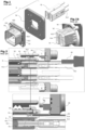
- Fig.1 to Fig.2 show an example of a prior art pass-through connector 9, comprising an inner head 91 to be assembled through a customer interface, called shield, 94 with an outer head assembly 92, 93.
- the shield 94 is to be fixed to a non represented wall with fixation means that may be known ones, or to be integral with said wall.
- the inner head received several electrical terminals 911 that are fixed to the end of cables 912. Such cables are for example connected with the terminals of a non represented power battery.
- Fig.1 the whole assembly shown in Fig.1 is only one connector, a connector fixed to a wall, and which is then ready to be mated with a counter connector (which counter connector is not represented in Fig. 1 ).
- the outer part comprises an outer head 93 with a fixation and shielding sleeve 92, and is arranged to be assembled with the inner head 91.
- Outer head 93 forms a socket which it is assembled with the shield 94 and bears cooperation means for ergonomically receiving a counter connector 8.
- cooperation means typically include poka-yoke guides 931 and retention protrusions 932 for the counter connector.
- fixation sleeve 92 also includes retention lances 923 that come into abutment with the outer head 93, hence preventing back movement of the inner head 91 out of outer head 93.
- disassembling the connector 9 may only be done by bending the retention lances 914 away from the inner head 91, which operation requests use of a long and thin tool 90 such as a screw driver, to be inserted between inner head 91 and shield 94. This is true for each of the retention lances, typically four of them which must moreover be actuated concurrently.
- One aim of the invention is to overcome some or all of the disadvantages of the prior art.
- it is intended to make assembling and disassembling of the pass-through connector easier, quicker and more reliable, especially for non specialist operators.
- a connector according to claim 1 a connector and counter-connector assembly according to claim 11.
- the disclosure also relates to a method for assembling and disassembling such a connector across a wall according to claims 12 and 13.
- Such pass-through connector which is adapted to be mated with a counter-connector, comprises a first head first head called inner head and a second head called outer head, adapted for being assembled with each other from either sides of a wall and across a possibly closed orifice of a shield and/or a wall, so as to bear said terminals and to be mated with said counter-connector.
- said pass-through connector comprises an outer hooking member on the outer head, and an inner hooking member on the inner head, arranged for engaging together for retaining said inner and outer heads together, once in their assembled positions. It comprises a locking element, mounted on the inner head, mobile between at least an unlocked position allowing assembling both heads together and a locked position preventing hooking members from disengage from each other, preferably by manual-only operation. Locking element further comprises one or several assistance members, that cooperates with at least one of said hooking members for disengaging said hooking members from one another, when said locking element is moved from its locked position to its unlocked position.
- the use of the CPA guarantees the functionality of the lock and acts as a secondary lock. It is ergonomic and the disassembly is done by deactivating the CPA.
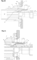
- Fig.3 to Fig.15 show an example of embodiment of a pass-through connector 7 according to the present disclosure.
- similar or identical elements have the same references.
- the pass-through connector 7 comprises an outer head 3 receiving and assembled with an inner head 1 across a shield 4 that may be fixed to or integral with a wall.
- inner head 1 At its mating extremity, inner head 1 has a double longitudinal cavity 10 in which are mounted two electrical terminals, possibly of a known type and not visible here. These terminals are fixed on two to-be-connected cables 192. Mating extremity of inner head 1 is to be inserted through the shield 4 and then into a longitudinal cavity 30 of the outer head 3.
- the connector 7 forms a wall socket that can receive a counter connector 8 with its own cables 812, said counter connector 8 being guided within the outer head cavity 30 with its counter terminals 811 mated with the terminals of the inner head 1.
- counter-connector 8 preferably comprises a locking mechanism and a "connection position assurance” system (CPA), between said counter connector 8 and the connector 7, that are not illustrated here, independently and in supplement of the present disclosure.
- CPA connection position assurance
- counter connector 8 could possibly be the same as in the prior art, with the same locking mechanism and CPA, as the shape of the inner head 1 and outer head 3 of the present connector 7 are not directly constrained by the functional features of the present disclosure, and could easily be adapted for compatibility with the shape of such counter connector.
- inner head 1 comprises itself a locking area 12, in which is mounted a locking element 2 that is slidably movable between an unlocked position (see Fig.6 , Fig.9 and Fig. 10 ) and a locked position (see Fig.12 and Fig.13 ).
- locking element 2 is a one-piece separated element, which is inserted into a longitudinal cavity included in the top part of the inner head 1.
- Locking element 2 comprises a transversal rear plate 23, from which longitudinally extends an assurance member, here embodied as a flexible central assurance arm 24, and two lateral locking arms 21, 22.
- the two lateral locking arms 21, 22 each have two guiding protrusions 218, 219 which are guided by longitudinally grooves of the locking area 12 of inner head 1.
- One 219 of the protrusions of the locking arms 21, 22 further have a hook shape that enables retaining the locking element 2 into the grooves 123 of locking area 12 by abutments 122.
- Fig.4 an orientation referential, used in the present disclosure, illustrating directions X for all "forward” directions and Z for all “upward” directions.
- Assurance arm 24 is elastically deformable in the vertical direction, and has on its free extremity a bottom oriented nose 241 with an external flat transverse forward oriented surface 2411 and a bottom-rear oriented slope 2412. Assurance arm 24 also has within its length a transverse protrusion 240 on both sides with a top oriented surface 2401, two lateral bottom-rear oriented slopes 2402, and two forward oriented surfaces 2403.
- Lateral locking arms 21, 22 are elastically deformable in the horizontal direction toward the interior, i.e. toward the central assurance arm 24. Each has on it free extremity an assistance cam 211, 221, laterally protruding toward interior, with a top-rear oriented slope 2111 and preferably a top-forward oriented slope 2112. Each locking arm 21, 22 also has on its internal part a lateral interior oriented closing protrusion 212, with a forward-bottom oriented slope.
- Locking area 12 comprises a flexible hooking loop 14 with a hooking bridge 140 between two parallel branches that horizontally extend from the top surface of the inner head 1, through an elastically deformable joint 149 that enables the hooking bridge 140, at the free extremity of said hooking loop 14, to be uplifted.
- hooking loop 14 Between its two branches, said free extremity of hooking loop 14 has a top-front oriented slope 141 and a rear oriented vertical abutment surface 142.
- aid assistance protrusion 111 has a forward-bottom oriented slope 1111, a rear-bottom oriented slope 1112 and a top-rear oriented slope 1113.
- Fig.6 shows, still with top wall 121 removed, the locking element 2 once inserted in the grooves of inner head 1 and in unlocked position.
- the nose 240 of its assurance arm 24 is inserted between the two branches of hooking loop 14 of inner head and may slide between them. Both extremities of its transverse protrusion 240 overlap the branches of the hooking loop 14 of inner head.
- Each assistance cam 211, 221 of lateral of locking arms 21, 22 of locking element 2 is under its respective lateral assistance protrusion 111 of the hooking loop 14 of inner head, and can longitudinally slide under it.
- outer head 3 has, in its longitudinal through cavity 30, a longitudinally oriented arm with a fixed hook 34 that extends toward the inner head 1. It has a vertical and transverse retention surface 342, arranged for retaining the rear oriented vertical abutment surface 142 of the bridge 140 of the hooking loop 14, when the inner head 1 is fully inserted into the outer head 3, as visible in Fig.9 .
- Fixed hook 34 of outer head also ends in a top-rear oriented slope 341.
- Fig.9 to Fig.13 schematically show the process of assembling the connector 7.
- All views of a "central cut” show a longitudinal vertical cut along a median plane AA, going through the fixed hook 34 and hooking bridge 140, as indicated in Fig.4 and Fig.8 .
- All views of an "offset cut” show un longitudinal vertical cut along a thereto parallel plane BB, offsetted from central plane AA and going through the assistance protrusions 111 of inner head and assistance cams 211 and closing cam 212 of locking element 2.
- inner head 1 is already provided with the locking element 2 in its unlocked position, and is presented at the entrance of the opening 40 of shield 4 and at entrance of cavity 30 of the inner head 3.
- inner head 1 has been inserted A1 and is assembled with outer head 3. Its hooking bridge 140 has been uplifted by the slope 341 of the fixed hook 34, and then elastically came down against the retention surface 342 of said fixed hook 34. Locking element 2 is still in unlocked position, and protrudes out of the top wall 121 by a distance P1.
- locking element 2 is fully pushed and its rear plate 23 comes in abutment against the edge of the top wall 121 of the locking area 12 of inner head 1. Its nose 241 has come back down under elasticity of the assurance arm 24, and/or possibly being pushed back by an optional downward slope (not represented here) extending from under the top wall 121. Protrusion distance P3 of the rear plate 23 has been reduced to its minimum, preferably zero. Such distance P3 is then a clearly visible indicator that the locking element 2 has been fully inserted and is now in its locked position.
- the inferior surface of the closing protrusions 212 of the locking arms 21 come in contact with the top of the top-rear oriented slope 1113 of the assistance protrusion 111 of the hooking loop of the inner head. While this functionality could be seen as optional, this contact makes sure that the hooking loop 14 is actually come back down, so as to be fully retained by the fixed hook of the outer head 3. It also forcibly maintains the hooking loop in its down position behind the fixed hook 34, thus effectively locking the inner head 1 assembled with the outer head 3.
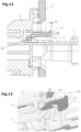
- Fig.14a to Fig.15b schematically show the process of disassembling the connector 7, such as for service on the finished system or vehicle. Disassembling is here illustrated starting from the situation of Fig.12 and Fig.13 , where the outer head and inner head are assembled around and through the shield 4 and/or the wall, and are locked together by the fully pushed locking element 2.
- a servicing operator starts pulling on the locking element 2 by its rear plate 23.
- a first part D1 of the backward movement of locking element drives upward the nose 241 of its assurance arm 24, by a contact cooperation of said nose 241 and its rear-bottom oriented slope 2412 with the top-front oriented slope 2412 of the hooking loop 14, as seen in Fig.14a .
- uplifting move U21 of assistance protrusion causes an uplifting of the free extremity of hooking loop 14 and hence an uplifting U20 of its bridge 140, so as to get it out and over the retention surface 342 of the fixed hook 34 of the outer head 3.
- unlocking inner head 1 and separating it from outer head 3 maybe done simply, in one continuous movement, manually and without any tool for this whole disassembling operation.
- Fig.17 illustrates a situation where the inner head 1 has been assembled with the outer head 3, but where the hooking bridge 140 of the inner head 1 has not come down in full and correct contact with the retention surface 342 of the outer head 3.
- the subsisting uplifted position of the hooking bridge 140 creates with its rear surface 142 an abutment for the front surface 2411 of the assurance arm 24 of the locking element 2, thus actually preventing it from being fully inserted under the top wall of the inner head.
- the rear oriented surface 143 of the branches 14 of the hooking loop creates an abutment for the front surface 2403 of the transverse protrusion 240 of the assurance arm 24 of the locking element 2.
- Disclosure thus provides better ease and reliability of installation and better serviceability as well, from the rear side, even when this area happens to provides only difficult access.
- cams 211 and protrusions 212 of locking element 2 are here exemplified in two instances distributed on two arms, it should be noted that other embodiments are also considered with more of them as well as with only one of each, as long as the same contact cooperation is arranged for each of here described functional surfaces and members. In the same spirit, similar variations of instances number are also considered for the assurance arm 24 and its nose 241 and slopes 2411, 2412. Similarly, hooking loop 14 is also considered with only one arm or more than two arms, and more than one "bridge" 140 and retention surface 342.
Landscapes
- Engineering & Computer Science (AREA)
- Manufacturing & Machinery (AREA)
- Details Of Connecting Devices For Male And Female Coupling (AREA)
Abstract
Disclosure relates to a pass-through connector (7), adapted to be mated with a counter-connector (8), comprising an inner head (1) and an outer head (3) to be assembled with each other, across an orifice (40) of a shield and/or wall, to bear terminals and be mated with said counter-connector.
Said connector comprises hooking members (34, 14) on both outer(3) and inner(1) heads, arranged for engaging together for retaining said heads together once in assembled position. It comprises a locking element (2), mounted on the inner head (1), mobile between an unlocked position (Fig.10) allowing assembling both heads together and a locked position (Fig.12) preventing hooking members disengaging from each other, preferably by manual-only operation. Locking element(2) comprises one or several assistance members (21,211), that cooperates with hooking members (14,111) for disengaging them from one another when said locking element is moved (D2) from its locked position to its unlocked position.
Description
- The present disclosure relates to the field of connectors, and in particular to the field of automotive connectors.
- Connectors are used to assemble several previously made elements in order to make a connection between them that allows electrical energy and/or signals to be transmitted between these elements. These elements can each be a cable or a motor or another type of device such as a computer or a sensor or a lighting device. According to the need, such connectors may have electrical contacts in greater or lesser number and in greater or lesser size.
- When the connector mounted on one cable is mated with another connector, which can be called a counter-connector, usually of a different and for example complementary type, its electrical contacts are themselves mated with corresponding counter contacts on the other side of the connection that are mounted in the counter connector.
- "Pass-through" connectors are used for connecting a cable with a non-flexible device, such as with a motor for powering it or with a whole electrical powered vehicle for charging its battery.
- Such a pass through connector commonly comprises an inner part and an outer part, on both sides of a wall and which are assembled together through an opening of said wall. Inner and outer are here conventionally used for meaning inner and outer sides of an enclosure, but the present disclosure is also applicable to the opposite configuration.
-
Fig.1 to Fig.2 show an example of a prior art pass-through connector 9, comprising aninner head 91 to be assembled through a customer interface, called shield, 94 with anouter head assembly shield 94 is to be fixed to a non represented wall with fixation means that may be known ones, or to be integral with said wall. - The inner head received several
electrical terminals 911 that are fixed to the end ofcables 912. Such cables are for example connected with the terminals of a non represented power battery. - It is to be noted that the whole assembly shown in
Fig.1 is only one connector, a connector fixed to a wall, and which is then ready to be mated with a counter connector (which counter connector is not represented inFig. 1 ). - The outer part comprises an
outer head 93 with a fixation andshielding sleeve 92, and is arranged to be assembled with theinner head 91.Outer head 93 forms a socket which it is assembled with theshield 94 and bears cooperation means for ergonomically receiving acounter connector 8. Such cooperation means typically include poka-yoke guides 931 andretention protrusions 932 for the counter connector. - In such prior art,
inner head 91 is retained inside the byretention lances 914, integral withfixation sleeve 92, that clips itself in a small cavity on the external surface of theinner head 91. As illustrated inFig.1b ,fixation sleeve 92 also includesretention lances 923 that come into abutment with theouter head 93, hence preventing back movement of theinner head 91 out ofouter head 93. - Thus, as illustrated in
Fig.2 , disassembling the connector 9 may only be done by bending theretention lances 914 away from theinner head 91, which operation requests use of a long andthin tool 90 such as a screw driver, to be inserted betweeninner head 91 andshield 94. This is true for each of the retention lances, typically four of them which must moreover be actuated concurrently. - Hence, in the prior art, pass-through outer header and inner header are difficult to disassemble from each other once they have been assembled together. Serviceability is made difficult for the final assembly, and thus for the whole system or vehicle it is used into. Also, such fixation by
lances 914 click-snapping is not very reliable for ensuring that retention is actually obtained, and is difficult to access for completion if retention is not completely produced by the sole insertion of the inner head. - One aim of the invention is to overcome some or all of the disadvantages of the prior art. In particular, it is intended to make assembling and disassembling of the pass-through connector easier, quicker and more reliable, especially for non specialist operators.
- These objectives are achieved partially or wholly, according to the disclosure, by a device and method having the features set forth in the claims. The below disclosure provides a solution for at least partially mitigate these drawbacks. he claims form an integral part of the technical description provided herein in connection with the disclosure.
- In this context it is disclosed a connector according to
claim 1, a connector and counter-connector assembly according to claim 11. The disclosure also relates to a method for assembling and disassembling such a connector across a wall according toclaims 12 and 13. - Such pass-through connector, which is adapted to be mated with a counter-connector, comprises a first head first head called inner head and a second head called outer head, adapted for being assembled with each other from either sides of a wall and across a possibly closed orifice of a shield and/or a wall, so as to bear said terminals and to be mated with said counter-connector.
- According to the disclosure, said pass-through connector comprises an outer hooking member on the outer head, and an inner hooking member on the inner head, arranged for engaging together for retaining said inner and outer heads together, once in their assembled positions. It comprises a locking element, mounted on the inner head, mobile between at least an unlocked position allowing assembling both heads together and a locked position preventing hooking members from disengage from each other, preferably by manual-only operation. Locking element further comprises one or several assistance members, that cooperates with at least one of said hooking members for disengaging said hooking members from one another, when said locking element is moved from its locked position to its unlocked position.
- Thanks to these provisions, disassembling and serviceability are made possible and easier, and more ergonomically, even if the rear side provides little or difficult access. Installation is also made easier and more reliable with little or no loss of compactness. Implementation in various systems or vehicles is made easier and more flexible, and with less design constraints.
- Its advantages are ease of installation and better serviceability from the rear side as well the area with difficult access. The use of the CPA guarantees the functionality of the lock and acts as a secondary lock. It is ergonomic and the disassembly is done by deactivating the CPA.
- Other advantages and features will become apparent on examination of the detailed description of three examples that are in no way limitative, and the attached drawings, in which:
-
Fig.1 is a schematic diagram showing in exploded view the components of a pass-through connector according to a prior art example; -
Fig.1b is a schematic diagram showing a detail of the prior art connector ofFig.1 , once assembled, with the outer head removed for more clarity; -
Fig.2 is a schematic diagram in longitudinal cut view showing the whole and a detail of the pass-through connector ofFig.1 when assembled on the shield and mated with a schematically represented counter connector; -
Fig.3 is a schematic on scale diagram showing the components of a pass-through connector according to an exemplary embodiment of the present disclosure, in exploded view and in perspective of the assembled connector illustrated with a schematized counter-connector; -
Fig.4 is a perspective view of the locking element of the embodiment ofFig.3 ; -
Fig.5 is a detailed perspective top view of an horizontal cut of the locking part of the inner head of the embodiment ofFig.3 ; -
Fig.6 is the same view asFig.5 with the locking element assembled with the inner head and in unlocked position; -
Fig.7 is a detailed top view of the assembly ofFig.6 , still with the top wall removed; -
Fig.8 is a perspective view of the outer head of the embodiment ofFig.3 ; -
Fig.9 is a front view of a longitudinal central cut of the connector ofFig.3 , before being assembled together; -
Fig. 10 is a front view of a longitudinal central cut of the connector ofFig.3 , once assembled on the fixation wall and before locking; -
Fig.11 is a detailed front view of a longitudinal central cut of the connector ofFig.3 , during the process of moving in the locking element; -
Fig.12 is a detailed front view of a longitudinal cut of the connector ofFig.3 , in locked position, showing a central cut; -
Fig.13 is a detailed front view of a longitudinal cut of the connector ofFig.3 , in locked position, showing an offset cut; -
Fig.14a and Fig.14b are detailed front views of a longitudinal cut of the connector ofFig.3 , in the process of extracting the locking element from its locked position, in the step of unlocking the locking element from the inner head, with a central cut and with an offset cut; -
Fig.15a and Fig.15b are detailed front views of a longitudinal cut of the connector ofFig.3 , in the process of extracting the locking element from its locked position, in the further step of the locking element assisting the unlocking of the inner head from the outer head, with a central cut and with an offset cut; -
Fig.16 is a front view of a longitudinal central cut of the connector ofFig.3 , once it has been unlocked and in the process of separating inner head from outer head; -
Fig.17 is a detailed front view of a longitudinal central cut of the connector ofFig.3 , in a situation where the locking element is preventing from being locked by the inner head being not completely inserted in the outer head. -
Fig.3 to Fig.15 show an example of embodiment of a pass-throughconnector 7 according to the present disclosure. In the various figures, similar or identical elements have the same references. - As illustrated in
Fig.3 , the pass-throughconnector 7 comprises anouter head 3 receiving and assembled with aninner head 1 across ashield 4 that may be fixed to or integral with a wall. At its mating extremity,inner head 1 has a doublelongitudinal cavity 10 in which are mounted two electrical terminals, possibly of a known type and not visible here. These terminals are fixed on two to-be-connected cables 192. Mating extremity ofinner head 1 is to be inserted through theshield 4 and then into alongitudinal cavity 30 of theouter head 3. Once assembled, with theouter head 3 fixed to the shield such as byscrews 38, theconnector 7 forms a wall socket that can receive acounter connector 8 with itsown cables 812, saidcounter connector 8 being guided within theouter head cavity 30 with itscounter terminals 811 mated with the terminals of theinner head 1. - In such mated assembly, counter-connector 8 preferably comprises a locking mechanism and a "connection position assurance" system (CPA), between said
counter connector 8 and theconnector 7, that are not illustrated here, independently and in supplement of the present disclosure. - It should be noted that
such counter connector 8 could possibly be the same as in the prior art, with the same locking mechanism and CPA, as the shape of theinner head 1 andouter head 3 of thepresent connector 7 are not directly constrained by the functional features of the present disclosure, and could easily be adapted for compatibility with the shape of such counter connector. - According to the present disclosure,
inner head 1 comprises itself a lockingarea 12, in which is mounted alocking element 2 that is slidably movable between an unlocked position (seeFig.6 ,Fig.9 andFig. 10 ) and a locked position (seeFig.12 and Fig.13 ). - As illustrated in
Fig.4 , lockingelement 2 is a one-piece separated element, which is inserted into a longitudinal cavity included in the top part of theinner head 1. Lockingelement 2 comprises a transversalrear plate 23, from which longitudinally extends an assurance member, here embodied as a flexiblecentral assurance arm 24, and twolateral locking arms lateral locking arms protrusions area 12 ofinner head 1. One 219 of the protrusions of the lockingarms locking element 2 into thegrooves 123 of lockingarea 12 byabutments 122. - In
Fig.4 is noted an orientation referential, used in the present disclosure, illustrating directions X for all "forward" directions and Z for all "upward" directions. -
Assurance arm 24 is elastically deformable in the vertical direction, and has on its free extremity a bottom orientednose 241 with an external flat transverse forward orientedsurface 2411 and a bottom-rear orientedslope 2412.Assurance arm 24 also has within its length atransverse protrusion 240 on both sides with a top orientedsurface 2401, two lateral bottom-rear orientedslopes 2402, and two forward oriented surfaces 2403. - Lateral locking
arms central assurance arm 24. Each has on it free extremity anassistance cam slope 2111 and preferably a top-forward orientedslope 2112. Each lockingarm protrusion 212, with a forward-bottom oriented slope. -
Fig.5 and Fig.6 show the interior of the lockingarea 12 of theinner head 1, with a horizontal cut so as to virtually remove itstop wall 121. Lockingarea 12 comprises a flexible hookingloop 14 with a hookingbridge 140 between two parallel branches that horizontally extend from the top surface of theinner head 1, through an elastically deformable joint 149 that enables the hookingbridge 140, at the free extremity of said hookingloop 14, to be uplifted. - Between its two branches, said free extremity of hooking
loop 14 has a top-front orientedslope 141 and a rear orientedvertical abutment surface 142. Each branch of the hookingloop 14, on its lateral external face, has alateral assistance protrusion 111. As visible onFig.13 ,aid assistance protrusion 111 has a forward-bottom orientedslope 1111, a rear-bottom orientedslope 1112 and a top-rear orientedslope 1113. -
Fig.6 shows, still withtop wall 121 removed, the lockingelement 2 once inserted in the grooves ofinner head 1 and in unlocked position. - The
nose 240 of itsassurance arm 24 is inserted between the two branches of hookingloop 14 of inner head and may slide between them. Both extremities of itstransverse protrusion 240 overlap the branches of the hookingloop 14 of inner head. Eachassistance cam arms element 2 is under its respectivelateral assistance protrusion 111 of the hookingloop 14 of inner head, and can longitudinally slide under it. - As illustrated in
Fig.8 and Fig.9 ,outer head 3 has, in its longitudinal throughcavity 30, a longitudinally oriented arm with a fixedhook 34 that extends toward theinner head 1. It has a vertical andtransverse retention surface 342, arranged for retaining the rear orientedvertical abutment surface 142 of thebridge 140 of the hookingloop 14, when theinner head 1 is fully inserted into theouter head 3, as visible inFig.9 . Fixedhook 34 of outer head also ends in a top-rear orientedslope 341. -
Fig.9 to Fig.13 schematically show the process of assembling theconnector 7. - All views of a "central cut" show a longitudinal vertical cut along a median plane AA, going through the fixed
hook 34 and hookingbridge 140, as indicated inFig.4 andFig.8 . All views of an "offset cut" show un longitudinal vertical cut along a thereto parallel plane BB, offsetted from central plane AA and going through theassistance protrusions 111 of inner head andassistance cams 211 andclosing cam 212 of lockingelement 2. - In
Fig.9 ,inner head 1 is already provided with the lockingelement 2 in its unlocked position, and is presented at the entrance of theopening 40 ofshield 4 and at entrance ofcavity 30 of theinner head 3. - In
Fig.10 ,inner head 1 has been inserted A1 and is assembled withouter head 3. Its hookingbridge 140 has been uplifted by theslope 341 of the fixedhook 34, and then elastically came down against theretention surface 342 of said fixedhook 34. Lockingelement 2 is still in unlocked position, and protrudes out of thetop wall 121 by a distance P1. - In
Fig.11 , lockingelement 2 is pushed A2 towardouter head 3 and undertop wall 121, protrusion distance of therear plate 23 is reduced to P2. By this movement A2, thenose 241 of theassurance arm 24 of lockingelement 2 is being uplifted by the raisingslope 341 of the fixedhook 34 ofouter head 3. Its previous position is here illustrated in dashed line. - In
Fig.12 , lockingelement 2 is fully pushed and itsrear plate 23 comes in abutment against the edge of thetop wall 121 of the lockingarea 12 ofinner head 1. Itsnose 241 has come back down under elasticity of theassurance arm 24, and/or possibly being pushed back by an optional downward slope (not represented here) extending from under thetop wall 121. Protrusion distance P3 of therear plate 23 has been reduced to its minimum, preferably zero. Such distance P3 is then a clearly visible indicator that the lockingelement 2 has been fully inserted and is now in its locked position. - As can be seen in
Fig.13 with an offset cut, the inferior surface of the closingprotrusions 212 of the lockingarms 21 come in contact with the top of the top-rear orientedslope 1113 of theassistance protrusion 111 of the hooking loop of the inner head. While this functionality could be seen as optional, this contact makes sure that the hookingloop 14 is actually come back down, so as to be fully retained by the fixed hook of theouter head 3. It also forcibly maintains the hooking loop in its down position behind the fixedhook 34, thus effectively locking theinner head 1 assembled with theouter head 3. -
Fig.14a to Fig.15b schematically show the process of disassembling theconnector 7, such as for service on the finished system or vehicle. Disassembling is here illustrated starting from the situation ofFig.12 and Fig.13 , where the outer head and inner head are assembled around and through theshield 4 and/or the wall, and are locked together by the fully pushed lockingelement 2. - In
Fig.14a and Fig.14b , a servicing operator starts pulling on thelocking element 2 by itsrear plate 23. In a unlocking step, a first part D1 of the backward movement of locking element drives upward thenose 241 of itsassurance arm 24, by a contact cooperation of saidnose 241 and its rear-bottom orientedslope 2412 with the top-front orientedslope 2412 of the hookingloop 14, as seen inFig.14a . - In
Fig.15a and Fig.15b , pulling goes on in second movement part D2. As seen inFig.6b , the closingprotrusion 212 of each lockingarm locking element 2 has recoiled sufficiently to uncover bothassistance protrusions 111 of the arms of the hookingloop 14, thus enabling said hooking loop to be uplifted. Then, simultaneously or offsetted, the recoil of theassistance cam 211 of each lockingarm element 2 comes in contact cooperation by its summit and its top-rear orientedslope 2111 with the bottom and the forward-bottom orientedsurface 1111 of theassistance protrusion 111 of the lockingarm 21 of the hookingloop 14, thus uplifting U21 saidassistance protrusion 111. As seen inFig.15a , uplifting move U21 of assistance protrusion causes an uplifting of the free extremity of hookingloop 14 and hence an uplifting U20 of itsbridge 140, so as to get it out and over theretention surface 342 of the fixedhook 34 of theouter head 3. - As illustrated in
Fig.16 , it is then possible to extract theinner head 1 out of theouter head 3 by simply pulling D3 on it, as illustrated by the gap E3 growing between bothparts connector 7. It may be done by directly pulling oninner head 1, or simply by going on pulling on therear plate 23 of thelocking element 2, as itslateral locking protrusions 219 will transmit the traction effort to the inner head through the latter'sabutment 122 within grooves of the itslocking area 12. - Thus, unlocking
inner head 1 and separating it fromouter head 3 maybe done simply, in one continuous movement, manually and without any tool for this whole disassembling operation. -
Fig.17 illustrates a situation where theinner head 1 has been assembled with theouter head 3, but where the hookingbridge 140 of theinner head 1 has not come down in full and correct contact with theretention surface 342 of theouter head 3. As it can be seen in the mixed-dashed line oval, the subsisting uplifted position of the hookingbridge 140 creates with itsrear surface 142 an abutment for thefront surface 2411 of theassurance arm 24 of thelocking element 2, thus actually preventing it from being fully inserted under the top wall of the inner head. Also or alternatively, the rear orientedsurface 143 of thebranches 14 of the hooking loop creates an abutment for thefront surface 2403 of thetransverse protrusion 240 of theassurance arm 24 of thelocking element 2. - The remaining protrusion distance P2' thus clearly shows to the operator that the
connector 7 is not fully assembled and cannot be locked. Oppositely, a fully inserted locking element (with distance P3) makes it visibly certain that the connector is fully assembled and locked. - Disclosure thus provides better ease and reliability of installation and better serviceability as well, from the rear side, even when this area happens to provides only difficult access.
- While
various cams 211 andprotrusions 212 of lockingelement 2 are here exemplified in two instances distributed on two arms, it should be noted that other embodiments are also considered with more of them as well as with only one of each, as long as the same contact cooperation is arranged for each of here described functional surfaces and members. In the same spirit, similar variations of instances number are also considered for theassurance arm 24 and itsnose 241 andslopes loop 14 is also considered with only one arm or more than two arms, and more than one "bridge" 140 andretention surface 342. - Also, it should be noted that the terms of "inner" and "outer" are not meant here as limitative, and could be swapped depending on the context of implementation of the connector.
- Of course, the disclosure is not limited to the examples just described, and many adjustments can be made to these examples without departing from the scope of the disclosure.
Claims (13)
- Pass-through connector (7), arranged to be fixed on both faces of a wall and adapted for mating with a counter-connector (8), said connector comprising:- one or several electrical terminals adapted for being removably connected with one or several counter-terminals (811) of said counter-connector (8),- a first head called inner head (1) and a second head called outer head (3), adapted for being assembled with each other from either sides of said wall and across a closed orifice of a shield (4) and/or a wall, so as to bear said terminals and to be mated with said counter-connector (8),said pass-through connector (7) being characterized:- in that it comprises an outer hooking member (34) fixed to or extending from the outer head (3), and an inner hooking member (14) fixed to or extending from the inner head (1),- in that said hooking members (34, 14) are arranged to engage with each other so as to retains said heads (1, 3) together, once in their assembled positions,- in that it comprises a locking element (2) which is mounted on the inner head (1) so as to be mobile, preferably by manual-only operation, between at least∘ an unlocked position, where it allows assembling both heads (1, 3) together and hooking both hooking members (34, 14) together, and∘ a locked position, where it prevents said hooking members (34, 14) from disengage from each other,- in that said locking element (2) comprises one or several assistance members (21, 22), that cooperates by contact with at least one (14) of said hooking members (14, 34) for disengaging said hooking members from one another, when said locking element (2) is moved (A2, A3) from its locked position to its unlocked position.
- Connector according to the preceding claim, characterized in that the hooking members (14, 34) are arranged for self-engaging with each other by the sole movement of assembling together the inner head (1) and the outer head (3),
in that the locking element (2) is slidably mounted within a cavity formed in the inner head (1) or between both heads (1, 3), where it is arranged for being moved:- from its locked position to its unlocked position through a pulling movement, toward a second abutment position, and- from its unlocked position to its locked position through a pushing movement (A2, A3) that engage it into said cavity, until a first abutment position, preferably where a clearly and unambiguously visible mark shows that said locking element (2) is actually in its locked position. - Connector according to any one of the preceding claims, characterized in that the inner hooking member (14) may be moved toward a direction (U20) called "upward" so as to be disengaged from the outer hooking member (34),
and in that the assistance member (21, 22) bears at least one assistance cam (211) arranged for cooperating (2111) with a surface (1111) of the inner hooking member (14) along a movement of the locking element (2) from its locked position toward its unlocked position, so as to uplift said inner hooking member (14) towards said upward direction (U20) and thus disengage it out of the outer hooking member (34, 342). - Connector according to any one of the preceding claims, characterized in that the inner hooking member (14) may be moved toward a direction called "upward" (U20, U21) so as to be disengaged from the outer hooking member (34),
and in that the assistance member (21, 22) bears at least one closing surface (212) arranged for cooperating with a surface (1113) of the inner hooking member (14) when the locking element (2) is in its locked position, so as to prevent said inner hooking member (14, 140) from being uplifted (U20) and thus preventing it to be disengaged from the outer hooking member (34, 342),
and preferably for cooperating with said surface (1113) of the inner hooking member (14) for driving it downwards into its engaged position when the locking element (2) is moved from its unlocked position toward its locked position. - Connector according to the preceding claim, characterized in that the assistance member (21, 22) has at least a closing protrusion (212) that bears the closing surface, and that is inserted between an assistance protrusion (111) of the inner hooking member (14) when the locking element (2) is moved from its unlocked position toward its locked position, while the assistance member (21, 22) is itself prevented from uplifting by a fixed part (121) of the inner head (1).
- Connector according to any one of the preceding claims, characterized in that it comprises an assurance member (24) provided with a nose (241) which, when the locking element (2) is moved from its unlocked position toward its locked position, is inserted between the inner hooking member (14) and a fixed part (121) of the inner head (1),
and in that said nose (241) has an forward abutment surface (2411) that comes in abutment with a rear abutment surface (142) of the inner hooking member (14) when the latter has not fully engaged (342) with the outer hooking member (34). - Connector according to the preceding claim, characterized in that the inner hooking member (14) has to be moved toward an "upward" direction (U20) so that an inner hooking part (140) of it may travel over an outer hooking part (341) of the outer hooking member (34), in particular raised by a fixed slope, when the locking element (2) is moved toward its locked position,and where said inner hooking part (140) has to be moved downward in order to come in abutment engagement with a retention surface (342) of the outer hooking member (34),and in that an assurance member (24) has an abutment surface (2411) that comes in abutment with a rear abutment surface (142) of the inner hooking member (14) when the latter has not fully moved over said outer hooking part (341), including its final downward movement of engaging with said retention surface (342).
- Connector according to the preceding claim, characterized in that the assurance member comprises an assurance arm (24) which is moved toward an "upward" direction by the same fixed slope (341) as the hooking member (14), when the locking element (2) is moved toward its locked position,
and preferably is moved toward an "upward" direction by a front slope (141) of the inner hooking part (140) of the inner hooking member (14) when the locking element (2) is extracted from its locked position toward its unlocked position. - Connector according to any one of claims 6 to 8, characterized in that the assurance member (24) and the assistance member (21, 22) are made as parallel separate arms extending toward the outer head (3) from a same handling plate (23) of the locking element (2), which is a stand-alone part slidably inserted within an pass-through and all-around closed (121) cavity of the inner head (1).
- Connector according to any one of the preceding claims, characterized in that the outer head (3) is adapted to be fixed to a shield (4) and/or wall, and the inner head (1) bears all the electrical terminals, and the inner head (1) is assembled to the outer head (3) by being inserted and fixed into a pass-through cavity (30) of the outer head (3), and is preferably fixed only to said outer head (3).
- Connecting assembly comprising a pass-through connector (7) to any one of the preceding claims fixed to a shield (4) and/or a wall and a counter-connector (8) mated with said pass-through connector (7).
- Method for fixing a pass-through connector on a wall, comprising the following steps:- providing a pass-through connector according to any one of claims 1 to 10, with its locking element (2) in its unlocked position,- connecting the terminals of said pass-through connector with a cable (192),- assembling (A1) together the inner head (1) and the outer head (3) of said pass-through connector (7) on both sides of said wall and across an orifice of said wall,- locking said assembly (1, 3) by moving (A2, A3) the locking element (2) of said pass-through connector from its unlocked position to its locked position.
- Method for disassembling a pass-through connector (7) according to any one of claims 1 to 10 from a shield (4) and/or wall it is fixed to, comprising the following steps:- starting moving (D1) its locking element (2) from its unlocking position towards its locking position, thus unlocking (212, 111) the inner hooking member (14),- going on moving (D2) said locking element (2) until its locking position, thus extracting (U21, U20) the inner hooking member (14) from its engaged position (142, 342) with the outer hooking member (34),- extracting (D3) the inner head (1) from the outer head (3), and then from the shield (4) and/or wall.
Priority Applications (3)
| Application Number | Priority Date | Filing Date | Title |
|---|---|---|---|
| EP23192761.7A EP4513685A1 (en) | 2023-08-22 | 2023-08-22 | Pass-through connector with locking element |
| CN202411151930.7A CN119518357A (en) | 2023-08-22 | 2024-08-21 | Feed-through connector with locking element |
| US18/811,684 US20250070513A1 (en) | 2023-08-22 | 2024-08-21 | Pass-through connector with locking element |
Applications Claiming Priority (1)
| Application Number | Priority Date | Filing Date | Title |
|---|---|---|---|
| EP23192761.7A EP4513685A1 (en) | 2023-08-22 | 2023-08-22 | Pass-through connector with locking element |
Publications (1)
| Publication Number | Publication Date |
|---|---|
| EP4513685A1 true EP4513685A1 (en) | 2025-02-26 |
Family
ID=87762665
Family Applications (1)
| Application Number | Title | Priority Date | Filing Date |
|---|---|---|---|
| EP23192761.7A Pending EP4513685A1 (en) | 2023-08-22 | 2023-08-22 | Pass-through connector with locking element |
Country Status (3)
| Country | Link |
|---|---|
| US (1) | US20250070513A1 (en) |
| EP (1) | EP4513685A1 (en) |
| CN (1) | CN119518357A (en) |
Citations (2)
| Publication number | Priority date | Publication date | Assignee | Title |
|---|---|---|---|---|
| US6045388A (en) * | 1998-09-02 | 2000-04-04 | Molex Incorporated | Electrical connector position assurance system |
| JP2021190160A (en) * | 2020-05-25 | 2021-12-13 | 矢崎総業株式会社 | connector |
-
2023
- 2023-08-22 EP EP23192761.7A patent/EP4513685A1/en active Pending
-
2024
- 2024-08-21 CN CN202411151930.7A patent/CN119518357A/en active Pending
- 2024-08-21 US US18/811,684 patent/US20250070513A1/en active Pending
Patent Citations (2)
| Publication number | Priority date | Publication date | Assignee | Title |
|---|---|---|---|---|
| US6045388A (en) * | 1998-09-02 | 2000-04-04 | Molex Incorporated | Electrical connector position assurance system |
| JP2021190160A (en) * | 2020-05-25 | 2021-12-13 | 矢崎総業株式会社 | connector |
Also Published As
| Publication number | Publication date |
|---|---|
| US20250070513A1 (en) | 2025-02-27 |
| CN119518357A (en) | 2025-02-25 |
Similar Documents
| Publication | Publication Date | Title |
|---|---|---|
| US5487678A (en) | Connector housing having a lock mechanism | |
| EP1333533B1 (en) | A connector | |
| EP2311151B1 (en) | Checkable plug-in connection and method for checking the connection state of a plug-in connection | |
| JP2624049B2 (en) | connector | |
| EP1672747B1 (en) | A connector | |
| US5169327A (en) | Connector including cam member operable for performing a fitting operation | |
| CN102171894B (en) | Electrical connector with terminal protection and centering device | |
| JPH10189145A (en) | Half mating prevention connector | |
| US6685500B2 (en) | Connector and a method of assembling a connector | |
| JPH09330757A (en) | connector | |
| US20060166544A1 (en) | Connector assembly | |
| US5378173A (en) | Connector assembly | |
| US20030114044A1 (en) | Connector and method of mounting a connector housing on a panel | |
| US7001215B2 (en) | Connector with inner and outer housings | |
| EP1710869B1 (en) | A connector device | |
| US20250070513A1 (en) | Pass-through connector with locking element | |
| US6769929B2 (en) | Connector and a connector assembly | |
| US7458841B2 (en) | Wire cover and a locking construction therefor | |
| EP3716413A1 (en) | Connector | |
| EP2317609A1 (en) | Connector, series of connectors and method of assembling it | |
| JP2004103557A (en) | Lever type mating connector | |
| JP3470866B2 (en) | Connector coupling device | |
| JP2024080954A (en) | Connector and terminal removal method therefor | |
| EP1801926B1 (en) | A connetor and connector assembly | |
| WO2010015892A1 (en) | Electrical connector with terminal position assurance and terminal protection device |
Legal Events
| Date | Code | Title | Description |
|---|---|---|---|
| PUAI | Public reference made under article 153(3) epc to a published international application that has entered the european phase |
Free format text: ORIGINAL CODE: 0009012 |
|
| STAA | Information on the status of an ep patent application or granted ep patent |
Free format text: STATUS: THE APPLICATION HAS BEEN PUBLISHED |
|
| AK | Designated contracting states |
Kind code of ref document: A1 Designated state(s): AL AT BE BG CH CY CZ DE DK EE ES FI FR GB GR HR HU IE IS IT LI LT LU LV MC ME MK MT NL NO PL PT RO RS SE SI SK SM TR |
|
| STAA | Information on the status of an ep patent application or granted ep patent |
Free format text: STATUS: REQUEST FOR EXAMINATION WAS MADE |
|
| 17P | Request for examination filed |
Effective date: 20250724 |