EP4513684A1 - Electrical connection terminal and electrical connection assembly - Google Patents
Electrical connection terminal and electrical connection assembly Download PDFInfo
- Publication number
- EP4513684A1 EP4513684A1 EP24194327.3A EP24194327A EP4513684A1 EP 4513684 A1 EP4513684 A1 EP 4513684A1 EP 24194327 A EP24194327 A EP 24194327A EP 4513684 A1 EP4513684 A1 EP 4513684A1
- Authority
- EP
- European Patent Office
- Prior art keywords
- electrical connection
- connection piece
- base
- flexible electrical
- flexible
- Prior art date
- Legal status (The legal status is an assumption and is not a legal conclusion. Google has not performed a legal analysis and makes no representation as to the accuracy of the status listed.)
- Pending
Links
Images



Classifications
-
- H—ELECTRICITY
- H01—ELECTRIC ELEMENTS
- H01R—ELECTRICALLY-CONDUCTIVE CONNECTIONS; STRUCTURAL ASSOCIATIONS OF A PLURALITY OF MUTUALLY-INSULATED ELECTRICAL CONNECTING ELEMENTS; COUPLING DEVICES; CURRENT COLLECTORS
- H01R12/00—Structural associations of a plurality of mutually-insulated electrical connecting elements, specially adapted for printed circuits, e.g. printed circuit boards [PCB], flat or ribbon cables, or like generally planar structures, e.g. terminal strips, terminal blocks; Coupling devices specially adapted for printed circuits, flat or ribbon cables, or like generally planar structures; Terminals specially adapted for contact with, or insertion into, printed circuits, flat or ribbon cables, or like generally planar structures
- H01R12/70—Coupling devices
- H01R12/7005—Guiding, mounting, polarizing or locking means; Extractors
- H01R12/7011—Locking or fixing a connector to a PCB
- H01R12/7035—Locking or fixing a connector to a PCB involving non-elastic deformation, e.g. plastic deformation, melting
-
- H—ELECTRICITY
- H01—ELECTRIC ELEMENTS
- H01R—ELECTRICALLY-CONDUCTIVE CONNECTIONS; STRUCTURAL ASSOCIATIONS OF A PLURALITY OF MUTUALLY-INSULATED ELECTRICAL CONNECTING ELEMENTS; COUPLING DEVICES; CURRENT COLLECTORS
- H01R4/00—Electrically-conductive connections between two or more conductive members in direct contact, i.e. touching one another; Means for effecting or maintaining such contact; Electrically-conductive connections having two or more spaced connecting locations for conductors and using contact members penetrating insulation
- H01R4/10—Electrically-conductive connections between two or more conductive members in direct contact, i.e. touching one another; Means for effecting or maintaining such contact; Electrically-conductive connections having two or more spaced connecting locations for conductors and using contact members penetrating insulation effected solely by twisting, wrapping, bending, crimping, or other permanent deformation
- H01R4/18—Electrically-conductive connections between two or more conductive members in direct contact, i.e. touching one another; Means for effecting or maintaining such contact; Electrically-conductive connections having two or more spaced connecting locations for conductors and using contact members penetrating insulation effected solely by twisting, wrapping, bending, crimping, or other permanent deformation by crimping
- H01R4/183—Electrically-conductive connections between two or more conductive members in direct contact, i.e. touching one another; Means for effecting or maintaining such contact; Electrically-conductive connections having two or more spaced connecting locations for conductors and using contact members penetrating insulation effected solely by twisting, wrapping, bending, crimping, or other permanent deformation by crimping for cylindrical elongated bodies, e.g. cables having circular cross-section
-
- H—ELECTRICITY
- H01—ELECTRIC ELEMENTS
- H01R—ELECTRICALLY-CONDUCTIVE CONNECTIONS; STRUCTURAL ASSOCIATIONS OF A PLURALITY OF MUTUALLY-INSULATED ELECTRICAL CONNECTING ELEMENTS; COUPLING DEVICES; CURRENT COLLECTORS
- H01R12/00—Structural associations of a plurality of mutually-insulated electrical connecting elements, specially adapted for printed circuits, e.g. printed circuit boards [PCB], flat or ribbon cables, or like generally planar structures, e.g. terminal strips, terminal blocks; Coupling devices specially adapted for printed circuits, flat or ribbon cables, or like generally planar structures; Terminals specially adapted for contact with, or insertion into, printed circuits, flat or ribbon cables, or like generally planar structures
- H01R12/50—Fixed connections
- H01R12/59—Fixed connections for flexible printed circuits, flat or ribbon cables or like structures
- H01R12/65—Fixed connections for flexible printed circuits, flat or ribbon cables or like structures characterised by the terminal
- H01R12/69—Fixed connections for flexible printed circuits, flat or ribbon cables or like structures characterised by the terminal deformable terminals, e.g. crimping terminals
-
- H—ELECTRICITY
- H01—ELECTRIC ELEMENTS
- H01R—ELECTRICALLY-CONDUCTIVE CONNECTIONS; STRUCTURAL ASSOCIATIONS OF A PLURALITY OF MUTUALLY-INSULATED ELECTRICAL CONNECTING ELEMENTS; COUPLING DEVICES; CURRENT COLLECTORS
- H01R11/00—Individual connecting elements providing two or more spaced connecting locations for conductive members which are, or may be, thereby interconnected, e.g. end pieces for wires or cables supported by the wire or cable and having means for facilitating electrical connection to some other wire, terminal, or conductive member, blocks of binding posts
- H01R11/11—End pieces or tapping pieces for wires, supported by the wire and for facilitating electrical connection to some other wire, terminal or conductive member
- H01R11/12—End pieces terminating in an eye, hook, or fork
-
- H—ELECTRICITY
- H01—ELECTRIC ELEMENTS
- H01R—ELECTRICALLY-CONDUCTIVE CONNECTIONS; STRUCTURAL ASSOCIATIONS OF A PLURALITY OF MUTUALLY-INSULATED ELECTRICAL CONNECTING ELEMENTS; COUPLING DEVICES; CURRENT COLLECTORS
- H01R12/00—Structural associations of a plurality of mutually-insulated electrical connecting elements, specially adapted for printed circuits, e.g. printed circuit boards [PCB], flat or ribbon cables, or like generally planar structures, e.g. terminal strips, terminal blocks; Coupling devices specially adapted for printed circuits, flat or ribbon cables, or like generally planar structures; Terminals specially adapted for contact with, or insertion into, printed circuits, flat or ribbon cables, or like generally planar structures
- H01R12/70—Coupling devices
- H01R12/77—Coupling devices for flexible printed circuits, flat or ribbon cables or like structures
- H01R12/81—Coupling devices for flexible printed circuits, flat or ribbon cables or like structures connecting to another cable except for flat or ribbon cable
-
- H—ELECTRICITY
- H01—ELECTRIC ELEMENTS
- H01R—ELECTRICALLY-CONDUCTIVE CONNECTIONS; STRUCTURAL ASSOCIATIONS OF A PLURALITY OF MUTUALLY-INSULATED ELECTRICAL CONNECTING ELEMENTS; COUPLING DEVICES; CURRENT COLLECTORS
- H01R13/00—Details of coupling devices of the kinds covered by groups H01R12/70 or H01R24/00 - H01R33/00
- H01R13/02—Contact members
-
- H—ELECTRICITY
- H01—ELECTRIC ELEMENTS
- H01R—ELECTRICALLY-CONDUCTIVE CONNECTIONS; STRUCTURAL ASSOCIATIONS OF A PLURALITY OF MUTUALLY-INSULATED ELECTRICAL CONNECTING ELEMENTS; COUPLING DEVICES; CURRENT COLLECTORS
- H01R4/00—Electrically-conductive connections between two or more conductive members in direct contact, i.e. touching one another; Means for effecting or maintaining such contact; Electrically-conductive connections having two or more spaced connecting locations for conductors and using contact members penetrating insulation
- H01R4/10—Electrically-conductive connections between two or more conductive members in direct contact, i.e. touching one another; Means for effecting or maintaining such contact; Electrically-conductive connections having two or more spaced connecting locations for conductors and using contact members penetrating insulation effected solely by twisting, wrapping, bending, crimping, or other permanent deformation
- H01R4/18—Electrically-conductive connections between two or more conductive members in direct contact, i.e. touching one another; Means for effecting or maintaining such contact; Electrically-conductive connections having two or more spaced connecting locations for conductors and using contact members penetrating insulation effected solely by twisting, wrapping, bending, crimping, or other permanent deformation by crimping
-
- H—ELECTRICITY
- H01—ELECTRIC ELEMENTS
- H01R—ELECTRICALLY-CONDUCTIVE CONNECTIONS; STRUCTURAL ASSOCIATIONS OF A PLURALITY OF MUTUALLY-INSULATED ELECTRICAL CONNECTING ELEMENTS; COUPLING DEVICES; CURRENT COLLECTORS
- H01R4/00—Electrically-conductive connections between two or more conductive members in direct contact, i.e. touching one another; Means for effecting or maintaining such contact; Electrically-conductive connections having two or more spaced connecting locations for conductors and using contact members penetrating insulation
- H01R4/10—Electrically-conductive connections between two or more conductive members in direct contact, i.e. touching one another; Means for effecting or maintaining such contact; Electrically-conductive connections having two or more spaced connecting locations for conductors and using contact members penetrating insulation effected solely by twisting, wrapping, bending, crimping, or other permanent deformation
- H01R4/18—Electrically-conductive connections between two or more conductive members in direct contact, i.e. touching one another; Means for effecting or maintaining such contact; Electrically-conductive connections having two or more spaced connecting locations for conductors and using contact members penetrating insulation effected solely by twisting, wrapping, bending, crimping, or other permanent deformation by crimping
- H01R4/182—Electrically-conductive connections between two or more conductive members in direct contact, i.e. touching one another; Means for effecting or maintaining such contact; Electrically-conductive connections having two or more spaced connecting locations for conductors and using contact members penetrating insulation effected solely by twisting, wrapping, bending, crimping, or other permanent deformation by crimping for flat conductive elements, e.g. flat cables
-
- H—ELECTRICITY
- H01—ELECTRIC ELEMENTS
- H01R—ELECTRICALLY-CONDUCTIVE CONNECTIONS; STRUCTURAL ASSOCIATIONS OF A PLURALITY OF MUTUALLY-INSULATED ELECTRICAL CONNECTING ELEMENTS; COUPLING DEVICES; CURRENT COLLECTORS
- H01R4/00—Electrically-conductive connections between two or more conductive members in direct contact, i.e. touching one another; Means for effecting or maintaining such contact; Electrically-conductive connections having two or more spaced connecting locations for conductors and using contact members penetrating insulation
- H01R4/24—Connections using contact members penetrating or cutting insulation or cable strands
- H01R4/2404—Connections using contact members penetrating or cutting insulation or cable strands the contact members having teeth, prongs, pins or needles penetrating the insulation
- H01R4/2407—Connections using contact members penetrating or cutting insulation or cable strands the contact members having teeth, prongs, pins or needles penetrating the insulation having saw-tooth projections
-
- H—ELECTRICITY
- H01—ELECTRIC ELEMENTS
- H01R—ELECTRICALLY-CONDUCTIVE CONNECTIONS; STRUCTURAL ASSOCIATIONS OF A PLURALITY OF MUTUALLY-INSULATED ELECTRICAL CONNECTING ELEMENTS; COUPLING DEVICES; CURRENT COLLECTORS
- H01R43/00—Apparatus or processes specially adapted for manufacturing, assembling, maintaining, or repairing of line connectors or current collectors or for joining electric conductors
- H01R43/04—Apparatus or processes specially adapted for manufacturing, assembling, maintaining, or repairing of line connectors or current collectors or for joining electric conductors for forming connections by deformation, e.g. crimping tool
- H01R43/048—Crimping apparatus or processes
Definitions
- the present invention relates to an electrical connection terminal and an electrical connection assembly comprising the electrical connection terminal.
- an electrical connection terminal that is electrically connected to a Flexible Printed Circuit (FPC) or a Flexible Flat Cable (FFC) typically includes a main body and a crimping part. Multiple electrical contact teeth are formed on both sides of the crimping part of the electrical connection terminal, which pierce through the insulation layer of the Flexible Printed Circuit or Flexible Flat Cable and is crimped onto the conductor of the Flexible Printed Circuit or Flexible Flat Cable to electrically connect with the conductor of the Flexible Printed Circuit or Flexible Flat Cable.
- FPC Flexible Printed Circuit
- FFC Flexible Flat Cable
- the rear end of the crimping part of the electrical connection terminal is connected to the main body, and the front end of the crimping part of the electrical connection terminal is not fixed to the Flexible Printed Circuit or Flexible Flat Cable.
- the present invention has been made to overcome or alleviate at least one aspect of the above mentioned disadvantages.
- an electrical connection terminal comprises of: a crimping part and a main body.
- the crimping part includes: a base having a front end and a rear end opposite to each other in its longitudinal direction and two opposite sides in its transverse direction; multiple conductive teeth respectively connected to both sides of the base and located between the front and rear ends of the base; and multiple fixing teeth respectively connected to both sides of the front end of the base.
- the main body is connected to the rear end of the base.
- the conductive tooth is suitable for piercing an insulator of a flexible electrical connection piece and being crimped onto a conductor of the flexible electrical connection piece to be electrically connected to the flexible electrical connection piece;
- the fixing teeth are suitable for piercing the insulator of the flexible electrical connection piece and being crimped onto the insulator of the flexible electrical connection piece to fix the front end of the base to the flexible electrical connection piece.
- the multiple fixing teeth include: a first fixing tooth connected to one side of the front end of the base; and a second fixing tooth connected to the other side of the front end of the base.
- the first fixing tooth and the adjacent second fixing tooth are staggered in the longitudinal direction.
- the multiple conductive teeth include: a first conductive tooth connected to one side of the base; and a second conductive tooth connected to the other side of the base.
- the first conductive tooth and the adjacent second conductive tooth are staggered in the longitudinal direction.
- the multiple conductive teeth include multiple first conductive teeth, which are spaced in the longitudinal direction; and/or the multiple conductive teeth include multiple second conductive teeth, which are spaced in the longitudinal direction.
- the base has a U-shaped cross-section and includes: a bottom plate extending along the longitudinal direction and the transverse direction; and two sidewalls connected to the transverse sides of the bottom plate, respectively.
- the sidewalls extend along the longitudinal direction and a thickness direction of the bottom plate.
- the first fixing tooth and the first conductive tooth are connected to the upper side of one of the two sidewalls; the second fixing tooth and the second conductive tooth are connected to the upper side of the other of the two sidewalls.
- a rib is formed on the bottom plate, and the rib extends a predetermined length along the longitudinal direction; the rib and the conductive teeth are used to respectively rest against the opposite sides of the conductor of the flexible electrical connection piece, to ensure reliable electrical contact between the conductive teeth and the conductor.
- the main body of the electrical connection terminal is suitable for mating with a mating terminal, for being welded or crimped to a conductive terminal, or for being welded or crimped to a wire.
- the electrical connection terminal is an integral stamped piece.
- an electrical connection assembly comprising of a flexible electrical connection piece comprising an insulator and a conductor provided within the insulator; and the above electrical connection terminal, the crimping part of which is crimped onto the flexible electrical connection piece.
- the conductive teeth of the crimping part pierce the insulator of the flexible electrical connection piece and are crimped onto the conductor of the flexible electrical connection piece to be electrically connected to the flexible electrical connection piece.
- the fixing teeth of the crimping part pierce the insulator of the flexible electrical connection piece and are crimped onto the insulator of the flexible electrical connection piece to fix the front end of the electrical connection terminal to the flexible electrical connection piece.
- the insulator of the flexible electrical connection piece is flat and has two surfaces opposite to each other in its thickness direction; the base and the fixing teeth of the crimping part are respectively pressed against the opposite surfaces of the insulator of the flexible electrical connection piece.
- the flexible electrical connection piece is a Flexible Printed Circuit or a Flexible Flat Cable.
- the front end of the crimping part of the electrical connection terminal is fixed to the flexible electrical connection piece, so that the front end of the crimping part of the electrical connection terminal can be moved synchronously with the flexible electrical connection piece and cannot be moved up and down relative to the flexible electrical connection piece, thereby avoiding the flexible electrical connection piece being cut off by the sharp edge of the front end of the crimping part.
- an electrical connection terminal comprises of a crimping part and a main body.
- the crimping part includes: a base having a front end and a rear end opposite to each other in its longitudinal direction and two opposite sides in its transverse direction; multiple conductive teeth respectively connected to both sides of the base and located between the front and rear ends of the base; and multiple fixing teeth respectively connected to both sides of the front end of the base.
- the main body is connected to the rear end of the base.
- the conductive tooth is suitable for piercing an insulator of a flexible electrical connection piece and being crimped onto a conductor of the flexible electrical connection piece to be electrically connected to the flexible electrical connection piece;
- the fixing teeth are suitable for piercing the insulator of the flexible electrical connection piece and being crimped onto the insulator of the flexible electrical connection piece to fix the front end of the base to the flexible electrical connection piece.
- an electrical connection assembly comprises of a flexible electrical connection piece comprising an insulator and a conductor provided within the insulator; and the above electrical connection terminal, the crimping part of which is crimped onto the flexible electrical connection piece.
- the conductive teeth of the crimping part pierce the insulator of the flexible electrical connection piece and are crimped onto the conductor of the flexible electrical connection piece to be electrically connected to the flexible electrical connection piece.
- the fixing teeth of the crimping part pierce the insulator of the flexible electrical connection piece and are crimped onto the insulator of the flexible electrical connection piece to fix the front end of the electrical connection terminal to the flexible electrical connection piece.
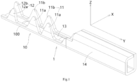
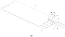
- Figure 1 shows an illustrative perspective view of an electrical connection terminal 1 according to an exemplary embodiment of the present invention, wherein the electrical connection terminal 1 has not yet been crimped onto the flexible electrical connection piece 2;
- Figure 2 shows a side view of the electrical connection terminal 1 according to an exemplary embodiment of the present invention, wherein the electrical connection terminal 1 has not yet been crimped onto the flexible electrical connection piece 2;
- Figure 3 shows an illustrative perspective view of an electrical connection assembly according to an exemplary embodiment of the present invention;
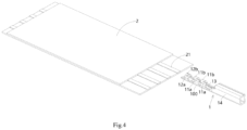
- Figure 4 shows an illustrative exploded view of an electrical connection assembly according to an exemplary embodiment of the present invention;
- Figure 5 shows an illustrative perspective view of an electrical connection terminal according to an exemplary embodiment of the present invention when viewed from the rear, wherein the electrical connection terminal 1 is in a crimped state;
- Figure 6 shows an illustrative perspective view of the electrical connection terminal 1 according to an exemplary embodiment of the present invention when viewed from the front side, wherein the electrical connection terminal 1 is in
- an electrical connection terminal 1 is disclosed.
- the electrical connection terminal 1 includes a crimping part 10 and a main body 14.
- the crimping part 10 includes a base 100, multiple conductive teeth 11, and multiple fixing teeth 12.
- the base 100 has a front end and rear end opposite to each other in its longitudinal direction Y, as well as two opposite sides in its transverse direction X.
- Multiple conductive teeth 11 are connected to both sides of the base 100 and are located between the front and rear ends of the base 100.
- Multiple fixing teeth 12 are connected to both sides of the front end of the base 100.
- the rear end of the base 100 is connected to the main body 14.
- the conductive teeth 11 of the crimping part 10 are suitable for piercing an insulator 20 of a flexible electrical connection piece 2 and being crimped onto a conductor 21 of the flexible electrical connection piece 2 to be electrically connected to the flexible electrical connection piece 2.
- the fixing teeth 12 of the crimping part 10 are suitable for piercing the insulator 20 of the flexible electrical connection piece 2 and being crimped onto the insulator 20 of the flexible electrical connection piece 2 to fix the front end of the base 100 to the flexible electrical connection piece 2.
- the front end of the crimping part 10 of the electrical connection terminal 1 is fixed to the flexible electrical connection piece 2, so that the front end of the crimping part 10 of the electrical connection terminal 1 can be moved synchronously with the flexible electrical connection piece 2 and will not be moved up and down relative to the flexible electrical connection piece 2, thereby avoiding the sharp edge of the front end of the crimping part 10 from cutting the flexible electrical connection piece 2.
- Figure 7 shows an illustrative plan view of the electrical connection terminal 1 according to an exemplary embodiment of the present invention when viewed from the top, wherein the electrical connection terminal 1 is in a crimped state;
- Figure 8 shows a cross-sectional view of an electrical connection assembly at one position according to an exemplary embodiment of the present invention;
- Figure 9 shows a cross-sectional view of the electrical connection assembly at another position according to an exemplary embodiment of the present invention.
- multiple fixing teeth 12 include: a first fixing tooth 12a and a second fixing tooth 12b.
- the first fixing tooth 12a is connected to one side of the front end of the base 100 (left side in the figure).
- the second fixing tooth 12b is connected to the other side of the front end of the base 100 (the right side in the figure).
- the first fixing tooth 12a and its adjacent second fixing tooth 12b are staggered in the longitudinal direction Y of the base 100. That is, the first fixing tooth 12a is not aligned with the adjacent second fixing tooth 12b in the transverse direction X of the base 100.
- multiple conductive teeth 11 include: a first conductive tooth 11a and a second conductive tooth 11b.
- the first conductive tooth 11a is connected to one side of the base 100.
- the second conductive tooth 11b is connected to the other side of the base 100.
- the first conductive tooth 11a and its adjacent second conductive tooth 11b are staggered in the longitudinal direction Y of the base 100. That is, the first conductive tooth 11a is not aligned with the adjacent second conductive tooth 11b in the transverse direction X of the base 100.
- multiple conductive teeth 11 include multiple first conductive teeth 11a.
- Multiple first conductive teeth 11a are connected to one side of the base 100 and spaced in the longitudinal direction Y of the base 100.
- multiple conductive teeth 11 include multiple second conductive teeth 11b.
- Multiple second conductive teeth 11b are connected to the other side of the base 100 and spaced in the longitudinal direction Y of the base 100.
- the cross-section of the base 100 of the crimping part 10 is U-shaped.
- the base 100 of the crimping part 10 includes a bottom plate 103 and two sidewalls 101 and 102.
- the bottom plate 103 of the base 100 extends along the longitudinal direction Y and the transverse direction X.
- the two sidewalls 101 and 102 of the base 100 are respectively connected to the transverse sides of the bottom plate 103.
- the sidewalls 101 and 102 extend along the longitudinal direction Y and a thickness direction Z of the bottom plate 103.
- the first fixing tooth 12a and the first conductive tooth 11a are connected to the upper side of one of the sidewalls 101 and 102.
- the second fixing tooth 12b and the second conductive tooth 11b are connected to the upper side of the other of the two sidewalls 101 and 102.
- a rib 13 is formed on the inner side of the bottom plate 103 of the base 100, which extends a predetermined length along the longitudinal direction Y
- the rib 13 and the conductive teeth 11 of the crimping part 10 are used to respectively rest against the opposite sides of conductor 21 of the flexible electrical connection piece 2, to ensure reliable electrical contact between the conductive teeth 11 and the conductor 21.
- the rib 13 is used to rest against the bottom side of the conductor 21 of the flexible electrical connection piece 2
- the ends of the conductive teeth 11 are used to rest against the top side of the conductor 21 of the flexible electrical connection piece 2, so that the conductor 21 of the flexible electrical connection piece 2 is clamped between the rib 13 and the ends of the conductive teeth 11 of the crimping part 10.
- the main body 14 of the electrical connection terminal 1 is suitable for mating with a mating terminal (not shown).
- the present invention is not limited to the illustrated embodiments, for example, the main body 14 of the electrical connection terminal 1 can also be formed to be suitable for being welded or crimped onto a conductive terminal or suitable for being welded or crimped onto a wire.
- the electrical connection terminal is an integral stamped piece. In this way, manufacturing costs can be reduced.
- an electrical connection assembly is also disclosed.
- the electrical connection assembly mainly includes: a flexible electrical connection piece 2 and the aforementioned electrical connection terminal 1.
- the flexible electrical connection piece 2 includes an insulator 20 and a conductor 21 provided in the insulator 20.
- the crimping part 10 of the electrical connection terminal 1 is crimped onto the flexible electrical connection piece 2.
- the conductive teeth 11 of the crimping part 10 of the electrical connection terminal 1 puncture the insulator 20 of the flexible electrical connection piece 2 and are crimped onto the conductor 21 to be electrically connected to the flexible electrical connection piece 2.
- the fixing teeth 12 of the crimping part 10 of the electrical connection terminal 1 pierce the insulator 20 of the flexible electrical connection piece 2 and are crimped onto the insulator 20 of the flexible electrical connection piece 2 to fix the front end of the electrical connection terminal 1 to the flexible electrical connection piece 2.
- the insulator 20 of the flexible electrical connection piece 2 is flat and has two surfaces opposite to each other in its thickness direction Z.
- the base 100 of the crimping part 10 and the fixing teeth 12 are respectively pressed against the opposite surfaces of the insulator 20 of the flexible electrical connection piece 2, so that the front end of the crimping part 10 is fixed to the insulator 20 of the flexible electrical connection piece 2.
- the base 100 is pressed against the bottom surface of the insulator 20 of the flexible electrical connection piece 2, the ends of the fixing teeth 12 are pressed against the top surface of the insulator 20 of the flexible electrical connection piece 2, so that the insulator 20 of the flexible electrical connection piece 2 is clamped between the base 100 and the ends of the fixing teeth 12 of the crimping part 10.
- the flexible electrical connection piece 2 can be a Flexible Printed Circuit (FPC) or a Flexible Flat Cable (FFC).
- FPC Flexible Printed Circuit
- FFC Flexible Flat Cable
Landscapes
- Engineering & Computer Science (AREA)
- Manufacturing & Machinery (AREA)
- Coupling Device And Connection With Printed Circuit (AREA)
- Multi-Conductor Connections (AREA)
- Connections By Means Of Piercing Elements, Nuts, Or Screws (AREA)
- Connections Effected By Soldering, Adhesion, Or Permanent Deformation (AREA)
Abstract
The present invention discloses an electrical connection terminal and an electrical connection assembly. The electrical connection terminal comprises of: a crimping part (10) and a main body (14). The crimping part (10) includes: a base (100) having a front end and a rear end opposite to each other in its longitudinal direction (Y) and two opposite sides in its transverse direction (X); multiple conductive teeth (11) respectively connected to both sides of the base (100) and located between the front and rear ends of the base (100); and multiple fixing teeth (12) respectively connected to both sides of the front end of the base (100). The main body (14) is connected to the rear end of the base (100). The conductive tooth (11) is suitable for piercing an insulator (20) of a flexible electrical connection piece (2) and being crimped onto a conductor (21) of the flexible electrical connection piece (2) to be electrically connected to the flexible electrical connection piece (2). The fixing teeth (12) are suitable for piercing the insulator (20) of the flexible electrical connection piece (2) and being crimped onto the insulator (20) of the flexible electrical connection piece (2) to fix the front end of the base (100) to the flexible electrical connection piece (2). In the present invention, the front end of the crimping part of the electrical connection terminal is fixed to the flexible electrical connection piece, so that the front end of the crimping part of the electrical connection terminal can be moved synchronously with the flexible electrical connection piece and cannot be moved up and down relative to the flexible electrical connection piece, thereby avoiding the flexible electrical connection piece being cut off by the sharp edge of the front end of the crimping part.
Description
- This application claims the benefit of Chinese Patent Application No.
CN202311033869.1 filed on August 16, 2023 - The present invention relates to an electrical connection terminal and an electrical connection assembly comprising the electrical connection terminal.
- In the prior art, an electrical connection terminal that is electrically connected to a Flexible Printed Circuit (FPC) or a Flexible Flat Cable (FFC) typically includes a main body and a crimping part. Multiple electrical contact teeth are formed on both sides of the crimping part of the electrical connection terminal, which pierce through the insulation layer of the Flexible Printed Circuit or Flexible Flat Cable and is crimped onto the conductor of the Flexible Printed Circuit or Flexible Flat Cable to electrically connect with the conductor of the Flexible Printed Circuit or Flexible Flat Cable.
- In the prior art, the rear end of the crimping part of the electrical connection terminal is connected to the main body, and the front end of the crimping part of the electrical connection terminal is not fixed to the Flexible Printed Circuit or Flexible Flat Cable. This causes the front end of the crimping part of the electrical connection terminal can be moved up and down relative to the Flexible Printed Circuit or Flexible Flat Cable, which makes the Flexible Printed Circuit or Flexible Flat Cable easily cut off by the sharp edge of the front end of the crimping part. Once the Flexible Printed Circuit or Flexible Flat Cable is cut off, it will cause the entire electrical connection assembly to be scrapped and need to be replaced.
- The present invention has been made to overcome or alleviate at least one aspect of the above mentioned disadvantages.
- According to an aspect of the present invention, there is provided an electrical connection terminal. The electrical connection terminal comprises of: a crimping part and a main body. The crimping part includes: a base having a front end and a rear end opposite to each other in its longitudinal direction and two opposite sides in its transverse direction; multiple conductive teeth respectively connected to both sides of the base and located between the front and rear ends of the base; and multiple fixing teeth respectively connected to both sides of the front end of the base. The main body is connected to the rear end of the base. The conductive tooth is suitable for piercing an insulator of a flexible electrical connection piece and being crimped onto a conductor of the flexible electrical connection piece to be electrically connected to the flexible electrical connection piece; the fixing teeth are suitable for piercing the insulator of the flexible electrical connection piece and being crimped onto the insulator of the flexible electrical connection piece to fix the front end of the base to the flexible electrical connection piece.
- According to an exemplary embodiment of the present invention, the multiple fixing teeth include: a first fixing tooth connected to one side of the front end of the base; and a second fixing tooth connected to the other side of the front end of the base. The first fixing tooth and the adjacent second fixing tooth are staggered in the longitudinal direction.
- According to another exemplary embodiment of the present invention, the multiple conductive teeth include: a first conductive tooth connected to one side of the base; and a second conductive tooth connected to the other side of the base. The first conductive tooth and the adjacent second conductive tooth are staggered in the longitudinal direction.
- According to another exemplary embodiment of the present invention, the multiple conductive teeth include multiple first conductive teeth, which are spaced in the longitudinal direction; and/or the multiple conductive teeth include multiple second conductive teeth, which are spaced in the longitudinal direction.
- According to another exemplary embodiment of the present invention, the base has a U-shaped cross-section and includes: a bottom plate extending along the longitudinal direction and the transverse direction; and two sidewalls connected to the transverse sides of the bottom plate, respectively. The sidewalls extend along the longitudinal direction and a thickness direction of the bottom plate.
- According to another exemplary embodiment of the present invention, the first fixing tooth and the first conductive tooth are connected to the upper side of one of the two sidewalls; the second fixing tooth and the second conductive tooth are connected to the upper side of the other of the two sidewalls.
- According to another exemplary embodiment of the present invention, a rib is formed on the bottom plate, and the rib extends a predetermined length along the longitudinal direction; the rib and the conductive teeth are used to respectively rest against the opposite sides of the conductor of the flexible electrical connection piece, to ensure reliable electrical contact between the conductive teeth and the conductor.
- According to another exemplary embodiment of the present invention, the main body of the electrical connection terminal is suitable for mating with a mating terminal, for being welded or crimped to a conductive terminal, or for being welded or crimped to a wire.
- According to another exemplary embodiment of the present invention, the electrical connection terminal is an integral stamped piece.
- According to another aspect of the present invention, there is provided an electrical connection assembly. The electrical connection assembly comprises of a flexible electrical connection piece comprising an insulator and a conductor provided within the insulator; and the above electrical connection terminal, the crimping part of which is crimped onto the flexible electrical connection piece. The conductive teeth of the crimping part pierce the insulator of the flexible electrical connection piece and are crimped onto the conductor of the flexible electrical connection piece to be electrically connected to the flexible electrical connection piece. The fixing teeth of the crimping part pierce the insulator of the flexible electrical connection piece and are crimped onto the insulator of the flexible electrical connection piece to fix the front end of the electrical connection terminal to the flexible electrical connection piece.
- According to an exemplary embodiment of the present invention, the insulator of the flexible electrical connection piece is flat and has two surfaces opposite to each other in its thickness direction; the base and the fixing teeth of the crimping part are respectively pressed against the opposite surfaces of the insulator of the flexible electrical connection piece.
- According to another exemplary embodiment of the present invention, the flexible electrical connection piece is a Flexible Printed Circuit or a Flexible Flat Cable.
- In the aforementioned exemplary embodiments of the present invention, the front end of the crimping part of the electrical connection terminal is fixed to the flexible electrical connection piece, so that the front end of the crimping part of the electrical connection terminal can be moved synchronously with the flexible electrical connection piece and cannot be moved up and down relative to the flexible electrical connection piece, thereby avoiding the flexible electrical connection piece being cut off by the sharp edge of the front end of the crimping part.
- The above and other features of the present invention will become more apparent by describing in detail exemplary embodiments thereof with reference to the accompanying drawings, in which:
-
Figure 1 shows an illustrative perspective view of an electrical connection terminal according to an exemplary embodiment of the present invention, wherein the electrical connection terminal has not yet been crimped onto the flexible electrical connection piece; -
Figure 2 shows a side view of an electrical connection terminal according to an exemplary embodiment of the present invention, wherein the electrical connection terminal has not yet been crimped onto the flexible electrical connection piece; -
Figure 3 shows an illustrative perspective view of an electrical connection assembly according to an exemplary embodiment of the present invention; -
Figure 4 shows an illustrative exploded view of an electrical connection assembly according to an exemplary embodiment of the present invention; -
Figure 5 shows an illustrative perspective view of an electrical connection terminal according to an exemplary embodiment of the present invention when viewed from the rear, wherein the electrical connection terminal is in a crimped state; -
Figure 6 shows an illustrative perspective view of an electrical connection terminal according to an exemplary embodiment of the present invention when viewed from the front side, wherein the electrical connection terminal is in a crimped state; -
Figure 7 shows an illustrative plan view of an electrical connection terminal according to an exemplary embodiment of the present invention when viewed from the top, wherein the electrical connection terminal is in a crimped state; -
Figure 8 shows a cross-sectional view of an electrical connection assembly at one position according to an exemplary embodiment of the present invention; and -
Figure 9 shows a cross-sectional view of the electrical connection assembly at another position according to an exemplary embodiment of the present invention. - Exemplary embodiments of the present disclosure will be described hereinafter in detail with reference to the attached drawings, wherein the like reference numerals refer to the like elements. The present disclosure may, however, be embodied in many different forms and should not be construed as being limited to the embodiment set forth herein; rather, these embodiments are provided so that the present disclosure will be thorough and complete, and will fully convey the concept of the disclosure to those skilled in the art.
- In the following detailed description, for purposes of explanation, numerous specific details are set forth in order to provide a thorough understanding of the disclosed embodiments. It will be apparent, however, that one or more embodiments may be practiced without these specific details. In other instances, well-known structures and devices are schematically shown in order to simplify the drawing.
- According to a general concept of the present invention, there is provided an electrical connection terminal. The electrical connection terminal comprises of a crimping part and a main body. The crimping part includes: a base having a front end and a rear end opposite to each other in its longitudinal direction and two opposite sides in its transverse direction; multiple conductive teeth respectively connected to both sides of the base and located between the front and rear ends of the base; and multiple fixing teeth respectively connected to both sides of the front end of the base. The main body is connected to the rear end of the base. The conductive tooth is suitable for piercing an insulator of a flexible electrical connection piece and being crimped onto a conductor of the flexible electrical connection piece to be electrically connected to the flexible electrical connection piece; the fixing teeth are suitable for piercing the insulator of the flexible electrical connection piece and being crimped onto the insulator of the flexible electrical connection piece to fix the front end of the base to the flexible electrical connection piece.
- According to another general concept of the present invention, there is provided an electrical connection assembly. The electrical connection assembly comprises of a flexible electrical connection piece comprising an insulator and a conductor provided within the insulator; and the above electrical connection terminal, the crimping part of which is crimped onto the flexible electrical connection piece. The conductive teeth of the crimping part pierce the insulator of the flexible electrical connection piece and are crimped onto the conductor of the flexible electrical connection piece to be electrically connected to the flexible electrical connection piece. The fixing teeth of the crimping part pierce the insulator of the flexible electrical connection piece and are crimped onto the insulator of the flexible electrical connection piece to fix the front end of the electrical connection terminal to the flexible electrical connection piece.
-
Figure 1 shows an illustrative perspective view of anelectrical connection terminal 1 according to an exemplary embodiment of the present invention, wherein theelectrical connection terminal 1 has not yet been crimped onto the flexibleelectrical connection piece 2;Figure 2 shows a side view of theelectrical connection terminal 1 according to an exemplary embodiment of the present invention, wherein theelectrical connection terminal 1 has not yet been crimped onto the flexibleelectrical connection piece 2;Figure 3 shows an illustrative perspective view of an electrical connection assembly according to an exemplary embodiment of the present invention;Figure 4 shows an illustrative exploded view of an electrical connection assembly according to an exemplary embodiment of the present invention;Figure 5 shows an illustrative perspective view of an electrical connection terminal according to an exemplary embodiment of the present invention when viewed from the rear, wherein theelectrical connection terminal 1 is in a crimped state;Figure 6 shows an illustrative perspective view of theelectrical connection terminal 1 according to an exemplary embodiment of the present invention when viewed from the front side, wherein theelectrical connection terminal 1 is in a crimped state. - As shown in
Figures 1 to 6 , in an exemplary embodiment of the present invention, anelectrical connection terminal 1 is disclosed. Theelectrical connection terminal 1 includes a crimpingpart 10 and amain body 14. The crimpingpart 10 includes abase 100, multipleconductive teeth 11, and multiple fixingteeth 12. Thebase 100 has a front end and rear end opposite to each other in its longitudinal direction Y, as well as two opposite sides in its transverse direction X. Multipleconductive teeth 11 are connected to both sides of thebase 100 and are located between the front and rear ends of thebase 100. Multiple fixingteeth 12 are connected to both sides of the front end of thebase 100. The rear end of thebase 100 is connected to themain body 14. - As shown in
Figures 1 to 6 , in the illustrated embodiments, theconductive teeth 11 of the crimpingpart 10 are suitable for piercing aninsulator 20 of a flexibleelectrical connection piece 2 and being crimped onto aconductor 21 of the flexibleelectrical connection piece 2 to be electrically connected to the flexibleelectrical connection piece 2. The fixingteeth 12 of the crimpingpart 10 are suitable for piercing theinsulator 20 of the flexibleelectrical connection piece 2 and being crimped onto theinsulator 20 of the flexibleelectrical connection piece 2 to fix the front end of the base 100 to the flexibleelectrical connection piece 2. - As shown in
Figures 1 to 6 , in the illustrated embodiments, the front end of the crimpingpart 10 of theelectrical connection terminal 1 is fixed to the flexibleelectrical connection piece 2, so that the front end of the crimpingpart 10 of theelectrical connection terminal 1 can be moved synchronously with the flexibleelectrical connection piece 2 and will not be moved up and down relative to the flexibleelectrical connection piece 2, thereby avoiding the sharp edge of the front end of the crimpingpart 10 from cutting the flexibleelectrical connection piece 2. -
Figure 7 shows an illustrative plan view of theelectrical connection terminal 1 according to an exemplary embodiment of the present invention when viewed from the top, wherein theelectrical connection terminal 1 is in a crimped state;Figure 8 shows a cross-sectional view of an electrical connection assembly at one position according to an exemplary embodiment of the present invention;Figure 9 shows a cross-sectional view of the electrical connection assembly at another position according to an exemplary embodiment of the present invention. - As shown in
Figures 1 to 9 , in the illustrated embodiments, multiple fixingteeth 12 include: afirst fixing tooth 12a and asecond fixing tooth 12b. Thefirst fixing tooth 12a is connected to one side of the front end of the base 100 (left side in the figure). Thesecond fixing tooth 12b is connected to the other side of the front end of the base 100 (the right side in the figure). Thefirst fixing tooth 12a and its adjacentsecond fixing tooth 12b are staggered in the longitudinal direction Y of thebase 100. That is, thefirst fixing tooth 12a is not aligned with the adjacentsecond fixing tooth 12b in the transverse direction X of thebase 100. - As shown in
Figures 1 to 9 , in the illustrated embodiments, multipleconductive teeth 11 include: a firstconductive tooth 11a and a secondconductive tooth 11b. The firstconductive tooth 11a is connected to one side of thebase 100. The secondconductive tooth 11b is connected to the other side of thebase 100. The firstconductive tooth 11a and its adjacent secondconductive tooth 11b are staggered in the longitudinal direction Y of thebase 100. That is, the firstconductive tooth 11a is not aligned with the adjacent secondconductive tooth 11b in the transverse direction X of thebase 100. - As shown in
Figures 1 to 9 , in the illustrated embodiments, multipleconductive teeth 11 include multiple firstconductive teeth 11a. Multiple firstconductive teeth 11a are connected to one side of thebase 100 and spaced in the longitudinal direction Y of thebase 100. - As shown in
Figures 1 to 9 , in the illustrated embodiments, multipleconductive teeth 11 include multiple secondconductive teeth 11b. Multiple secondconductive teeth 11b are connected to the other side of thebase 100 and spaced in the longitudinal direction Y of thebase 100. - As shown in
Figures 1 to 9 , in the illustrated embodiment, the cross-section of thebase 100 of the crimpingpart 10 is U-shaped. Thebase 100 of the crimpingpart 10 includes abottom plate 103 and twosidewalls bottom plate 103 of thebase 100 extends along the longitudinal direction Y and the transverse direction X. The twosidewalls bottom plate 103. Thesidewalls bottom plate 103. - As shown in
Figures 1 to 9 , in the illustrated embodiments, thefirst fixing tooth 12a and the firstconductive tooth 11a are connected to the upper side of one of thesidewalls second fixing tooth 12b and the secondconductive tooth 11b are connected to the upper side of the other of the twosidewalls - As shown in
Figures 1 to 9 , in the illustrated embodiments, arib 13 is formed on the inner side of thebottom plate 103 of thebase 100, which extends a predetermined length along the longitudinal direction Y Therib 13 and theconductive teeth 11 of the crimpingpart 10 are used to respectively rest against the opposite sides ofconductor 21 of the flexibleelectrical connection piece 2, to ensure reliable electrical contact between theconductive teeth 11 and theconductor 21. That is, therib 13 is used to rest against the bottom side of theconductor 21 of the flexibleelectrical connection piece 2, the ends of theconductive teeth 11 are used to rest against the top side of theconductor 21 of the flexibleelectrical connection piece 2, so that theconductor 21 of the flexibleelectrical connection piece 2 is clamped between therib 13 and the ends of theconductive teeth 11 of the crimpingpart 10. - As shown in
Figures 1 to 9 , in the illustrated embodiments, themain body 14 of theelectrical connection terminal 1 is suitable for mating with a mating terminal (not shown). However, the present invention is not limited to the illustrated embodiments, for example, themain body 14 of theelectrical connection terminal 1 can also be formed to be suitable for being welded or crimped onto a conductive terminal or suitable for being welded or crimped onto a wire. - As shown in
Figures 1 to 9 , in the illustrated embodiments, the electrical connection terminal is an integral stamped piece. In this way, manufacturing costs can be reduced. - As shown in
Figures 1 to 9 , in another exemplary embodiment of the present invention, an electrical connection assembly is also disclosed. The electrical connection assembly mainly includes: a flexibleelectrical connection piece 2 and the aforementionedelectrical connection terminal 1. The flexibleelectrical connection piece 2 includes aninsulator 20 and aconductor 21 provided in theinsulator 20. The crimpingpart 10 of theelectrical connection terminal 1 is crimped onto the flexibleelectrical connection piece 2. - As shown in
Figures 1 to 9 , in the illustrated embodiments, theconductive teeth 11 of the crimpingpart 10 of theelectrical connection terminal 1 puncture theinsulator 20 of the flexibleelectrical connection piece 2 and are crimped onto theconductor 21 to be electrically connected to the flexibleelectrical connection piece 2. The fixingteeth 12 of the crimpingpart 10 of theelectrical connection terminal 1 pierce theinsulator 20 of the flexibleelectrical connection piece 2 and are crimped onto theinsulator 20 of the flexibleelectrical connection piece 2 to fix the front end of theelectrical connection terminal 1 to the flexibleelectrical connection piece 2. - As shown in
Figures 1 to 9 , in the illustrated embodiments, theinsulator 20 of the flexibleelectrical connection piece 2 is flat and has two surfaces opposite to each other in its thickness direction Z. Thebase 100 of the crimpingpart 10 and the fixingteeth 12 are respectively pressed against the opposite surfaces of theinsulator 20 of the flexibleelectrical connection piece 2, so that the front end of the crimpingpart 10 is fixed to theinsulator 20 of the flexibleelectrical connection piece 2. That is, thebase 100 is pressed against the bottom surface of theinsulator 20 of the flexibleelectrical connection piece 2, the ends of the fixingteeth 12 are pressed against the top surface of theinsulator 20 of the flexibleelectrical connection piece 2, so that theinsulator 20 of the flexibleelectrical connection piece 2 is clamped between the base 100 and the ends of the fixingteeth 12 of the crimpingpart 10. - As shown in
Figures 1 to 9 , in the illustrated embodiments, the flexibleelectrical connection piece 2 can be a Flexible Printed Circuit (FPC) or a Flexible Flat Cable (FFC). - It should be appreciated for those skilled in this art that the above embodiments are intended to be illustrated, and not restrictive. For example, many modifications may be made to the above embodiments by those skilled in this art, and various features described in different embodiments may be freely combined with each other without conflicting in configuration or principle.
- Although several exemplary embodiments have been shown and described, it would be appreciated by those skilled in the art that various changes or modifications may be made in these embodiments without departing from the principles and spirit of the disclosure, the scope of which is defined in the claims and their equivalents.
- As used herein, an element recited in the singular and proceeded with the word "a" or "an" should be understood as not excluding plural of said elements or steps, unless such exclusion is explicitly stated. Furthermore, references to "one embodiment" of the present invention are not intended to be interpreted as excluding the existence of additional embodiments that also incorporate the recited features. Moreover, unless explicitly stated to the contrary, embodiments "comprising" or "having" an element or a plurality of elements having a particular property may include additional such elements not having that property.
Claims (12)
- An electrical connection terminal, comprising:a crimping part (10) includes:a base (100) having a front end and a rear end opposite to each other in its longitudinal direction (Y) and two opposite sides in its transverse direction (X);multiple conductive teeth (11) respectively connected to both sides of the base (100) and located between the front and rear ends of the base (100); andmultiple fixing teeth (12) respectively connected to both sides of the front end of the base (100); anda main body (14) which is connected to the rear end of the base (100),wherein the conductive tooth (11) is suitable for piercing an insulator (20) of a flexible electrical connection piece (2) and being crimped onto a conductor (21) of the flexible electrical connection piece (2) to be electrically connected to the flexible electrical connection piece (2),wherein the fixing teeth (12) are suitable for piercing the insulator (20) of the flexible electrical connection piece (2) and being crimped onto the insulator (20) of the flexible electrical connection piece (2) to fix the front end of the base (100) to the flexible electrical connection piece (2).
- The electrical connection terminal according to claim 1,wherein the multiple fixing teeth (12) include:a first fixing tooth (12a) connected to one side of the front end of the base (100); anda second fixing tooth (12b) connected to the other side of the front end of the base (100),wherein the first fixing tooth (12a) and the adjacent second fixing tooth (12b) are staggered in the longitudinal direction (Y).
- The electrical connection terminal according to claim 2,wherein the multiple conductive teeth (11) include:a first conductive tooth (11a) connected to one side of the base (100); anda second conductive tooth (11b) connected to the other side of the base (100),wherein the first conductive tooth (11a) and the adjacent second conductive tooth (11b) are staggered in the longitudinal direction (Y).
- The electrical connection terminal according to claim 3,wherein the multiple conductive teeth (11) include multiple first conductive teeth (11a), which are spaced in the longitudinal direction (Y); and/orwherein the multiple conductive teeth (11) include multiple second conductive teeth (11b), which are spaced in the longitudinal direction (Y).
- The electrical connection terminal according to claim 3,wherein the base (100) has a U-shaped cross-section and includes:a bottom plate (103) extending along the longitudinal direction (Y) and the transverse direction (X); andtwo sidewalls (101, 102) connected to the transverse sides of the bottom plate (103), respectively,wherein the sidewalls (101, 102) extend along the longitudinal direction (Y) and a thickness direction (Z) of the bottom plate (103).
- The electrical connection terminal according to claim 5,wherein the first fixing tooth (12a) and the first conductive tooth (11a) are connected to the upper side of one of the two sidewalls (101, 102);wherein the second fixing tooth (12b) and the second conductive tooth (11b) are connected to the upper side of the other of the two sidewalls (101, 102).
- The electrical connection terminal according to claim 5,wherein a rib (13) is formed on the bottom plate (103), and the rib (13) extends a predetermined length along the longitudinal direction (Y);wherein the rib (13) and the conductive teeth (11) are used to respectively rest against the opposite sides of the conductor (21) of the flexible electrical connection piece (2), to ensure reliable electrical contact between the conductive teeth (11) and the conductor (21).
- The electrical connection terminal according to claim 1,
wherein the main body (14) of the electrical connection terminal (1) is suitable for mating with a mating terminal, for being welded or crimped to a conductive terminal, or for being welded or crimped to a wire. - The electrical connection terminal according to claim 1,
wherein the electrical connection terminal is an integral stamped piece. - An electrical connection assembly, comprising:a flexible electrical connection piece (2) comprising an insulator (20) and a conductor (21) provided within the insulator (20); andthe electrical connection terminal (1) as claimed in any one of claims 1-9, the crimping part (10) of which is crimped onto the flexible electrical connection piece (2),wherein the conductive teeth (11) of the crimping part (10) pierce the insulator (20) of the flexible electrical connection piece (2) and are crimped onto the conductor (21) of the flexible electrical connection piece (2) to be electrically connected to the flexible electrical connection piece (2),wherein the fixing teeth (12) of the crimping part (10) pierce the insulator (20) of the flexible electrical connection piece (2) and are crimped onto the insulator (20) of the flexible electrical connection piece (2) to fix the front end of the electrical connection terminal (1) to the flexible electrical connection piece (2).
- The electrical connection assembly according to claim 10,wherein the insulator (20) of the flexible electrical connection piece (2) is flat and has two surfaces opposite to each other in its thickness direction (Z);wherein the base (100) and the fixing teeth (12) of the crimping part (10) are respectively pressed against the opposite surfaces of the insulator (20) of the flexible electrical connection piece (2).
- The electrical connection assembly according to claim 10,
wherein the flexible electrical connection piece (2) is a Flexible Printed Circuit or a Flexible Flat Cable.
Applications Claiming Priority (1)
| Application Number | Priority Date | Filing Date | Title |
|---|---|---|---|
| CN202311033869.1A CN119495961A (en) | 2023-08-16 | 2023-08-16 | Electrical connection terminal and electrical connection assembly |
Publications (1)
| Publication Number | Publication Date |
|---|---|
| EP4513684A1 true EP4513684A1 (en) | 2025-02-26 |
Family
ID=92409196
Family Applications (1)
| Application Number | Title | Priority Date | Filing Date |
|---|---|---|---|
| EP24194327.3A Pending EP4513684A1 (en) | 2023-08-16 | 2024-08-13 | Electrical connection terminal and electrical connection assembly |
Country Status (5)
| Country | Link |
|---|---|
| US (1) | US20250062555A1 (en) |
| EP (1) | EP4513684A1 (en) |
| JP (1) | JP2025028007A (en) |
| KR (1) | KR20250026127A (en) |
| CN (1) | CN119495961A (en) |
Citations (3)
| Publication number | Priority date | Publication date | Assignee | Title |
|---|---|---|---|---|
| US4082402A (en) * | 1974-01-09 | 1978-04-04 | Amp Incorporated | Flat flexible cable terminal and electrical connection |
| WO2015030241A1 (en) * | 2013-09-02 | 2015-03-05 | 矢崎総業株式会社 | Terminal-equipped flat cable, and flat cable |
| US20210313719A1 (en) * | 2020-04-06 | 2021-10-07 | Nippon Mektron, Ltd. | Flexible printed wiring board with crimp terminal |
-
2023
- 2023-08-16 CN CN202311033869.1A patent/CN119495961A/en active Pending
-
2024
- 2024-08-13 US US18/801,969 patent/US20250062555A1/en active Pending
- 2024-08-13 JP JP2024134742A patent/JP2025028007A/en active Pending
- 2024-08-13 EP EP24194327.3A patent/EP4513684A1/en active Pending
- 2024-08-13 KR KR1020240108138A patent/KR20250026127A/en active Pending
Patent Citations (3)
| Publication number | Priority date | Publication date | Assignee | Title |
|---|---|---|---|---|
| US4082402A (en) * | 1974-01-09 | 1978-04-04 | Amp Incorporated | Flat flexible cable terminal and electrical connection |
| WO2015030241A1 (en) * | 2013-09-02 | 2015-03-05 | 矢崎総業株式会社 | Terminal-equipped flat cable, and flat cable |
| US20210313719A1 (en) * | 2020-04-06 | 2021-10-07 | Nippon Mektron, Ltd. | Flexible printed wiring board with crimp terminal |
Also Published As
| Publication number | Publication date |
|---|---|
| KR20250026127A (en) | 2025-02-25 |
| US20250062555A1 (en) | 2025-02-20 |
| CN119495961A (en) | 2025-02-21 |
| JP2025028007A (en) | 2025-02-28 |
Similar Documents
| Publication | Publication Date | Title |
|---|---|---|
| US7189105B2 (en) | Connector suitable for connection of a thin sheet member | |
| US9431720B2 (en) | Connecting structure and connecting method of flat circuit body and terminal | |
| US20100022122A1 (en) | Connector | |
| US9325089B2 (en) | Connecting structure and connecting method of flat circuit body and terminal | |
| EP1326306B1 (en) | Connecting member for flat circuit member and method of connecting the connecting member and the flat circuit member | |
| US20140318849A1 (en) | Flat circuit body with terminal and manufacturing method thereof | |
| US6565376B2 (en) | Flat cable terminal | |
| JP4084292B2 (en) | Pressure welding structure of coaxial cable | |
| EP4513684A1 (en) | Electrical connection terminal and electrical connection assembly | |
| JP4509866B2 (en) | Terminal fitting | |
| US7001203B2 (en) | Piercing terminal for coaxial cable | |
| CN220544273U (en) | Electric connection terminal and electric connection assembly | |
| EP1662615A2 (en) | Electric connector | |
| JP2005141984A (en) | Piercing contact, flat cable with piercing contact, flat cable with connector, and method of manufacturing the same | |
| US20240266767A1 (en) | Flat Flexible Cable Connector | |
| JP4247180B2 (en) | Electrical connector | |
| EP1691452A2 (en) | Connecting member for flat circuit member and method of connecting the connecting member and the flat circuit member | |
| US6086409A (en) | Connector for flat-conductor flat cables or flexible circuits | |
| JP4842634B2 (en) | Flat circuit body | |
| JP2003115339A (en) | Piercing terminal | |
| JP2006172979A (en) | Electric connector |
Legal Events
| Date | Code | Title | Description |
|---|---|---|---|
| PUAI | Public reference made under article 153(3) epc to a published international application that has entered the european phase |
Free format text: ORIGINAL CODE: 0009012 |
|
| STAA | Information on the status of an ep patent application or granted ep patent |
Free format text: STATUS: THE APPLICATION HAS BEEN PUBLISHED |
|
| AK | Designated contracting states |
Kind code of ref document: A1 Designated state(s): AL AT BE BG CH CY CZ DE DK EE ES FI FR GB GR HR HU IE IS IT LI LT LU LV MC ME MK MT NL NO PL PT RO RS SE SI SK SM TR |
|
| STAA | Information on the status of an ep patent application or granted ep patent |
Free format text: STATUS: REQUEST FOR EXAMINATION WAS MADE |
|
| 17P | Request for examination filed |
Effective date: 20250812 |