EP4513674A1 - System with dual-function antenna structure and associated methods - Google Patents
System with dual-function antenna structure and associated methods Download PDFInfo
- Publication number
- EP4513674A1 EP4513674A1 EP24179777.8A EP24179777A EP4513674A1 EP 4513674 A1 EP4513674 A1 EP 4513674A1 EP 24179777 A EP24179777 A EP 24179777A EP 4513674 A1 EP4513674 A1 EP 4513674A1
- Authority
- EP
- European Patent Office
- Prior art keywords
- dual
- antenna
- antenna structure
- antenna elements
- function
- Prior art date
- Legal status (The legal status is an assumption and is not a legal conclusion. Google has not performed a legal analysis and makes no representation as to the accuracy of the status listed.)
- Pending
Links
Images



Classifications
-
- H—ELECTRICITY
- H01—ELECTRIC ELEMENTS
- H01Q—ANTENNAS, i.e. RADIO AERIALS
- H01Q1/00—Details of, or arrangements associated with, antennas
- H01Q1/27—Adaptation for use in or on movable bodies
- H01Q1/28—Adaptation for use in or on aircraft, missiles, satellites, or balloons
-
- H—ELECTRICITY
- H01—ELECTRIC ELEMENTS
- H01Q—ANTENNAS, i.e. RADIO AERIALS
- H01Q1/00—Details of, or arrangements associated with, antennas
- H01Q1/27—Adaptation for use in or on movable bodies
- H01Q1/28—Adaptation for use in or on aircraft, missiles, satellites, or balloons
- H01Q1/281—Nose antennas
-
- G—PHYSICS
- G01—MEASURING; TESTING
- G01S—RADIO DIRECTION-FINDING; RADIO NAVIGATION; DETERMINING DISTANCE OR VELOCITY BY USE OF RADIO WAVES; LOCATING OR PRESENCE-DETECTING BY USE OF THE REFLECTION OR RERADIATION OF RADIO WAVES; ANALOGOUS ARRANGEMENTS USING OTHER WAVES
- G01S7/00—Details of systems according to groups G01S13/00, G01S15/00, G01S17/00
- G01S7/02—Details of systems according to groups G01S13/00, G01S15/00, G01S17/00 of systems according to group G01S13/00
- G01S7/021—Auxiliary means for detecting or identifying radar signals or the like, e.g. radar jamming signals
-
- G—PHYSICS
- G01—MEASURING; TESTING
- G01S—RADIO DIRECTION-FINDING; RADIO NAVIGATION; DETERMINING DISTANCE OR VELOCITY BY USE OF RADIO WAVES; LOCATING OR PRESENCE-DETECTING BY USE OF THE REFLECTION OR RERADIATION OF RADIO WAVES; ANALOGOUS ARRANGEMENTS USING OTHER WAVES
- G01S7/00—Details of systems according to groups G01S13/00, G01S15/00, G01S17/00
- G01S7/02—Details of systems according to groups G01S13/00, G01S15/00, G01S17/00 of systems according to group G01S13/00
- G01S7/38—Jamming means, e.g. producing false echoes
-
- H—ELECTRICITY
- H01—ELECTRIC ELEMENTS
- H01Q—ANTENNAS, i.e. RADIO AERIALS
- H01Q1/00—Details of, or arrangements associated with, antennas
- H01Q1/12—Supports; Mounting means
- H01Q1/22—Supports; Mounting means by structural association with other equipment or articles
- H01Q1/24—Supports; Mounting means by structural association with other equipment or articles with receiving set
-
- H—ELECTRICITY
- H01—ELECTRIC ELEMENTS
- H01Q—ANTENNAS, i.e. RADIO AERIALS
- H01Q1/00—Details of, or arrangements associated with, antennas
- H01Q1/27—Adaptation for use in or on movable bodies
- H01Q1/32—Adaptation for use in or on road or rail vehicles
- H01Q1/3208—Adaptation for use in or on road or rail vehicles characterised by the application wherein the antenna is used
-
- H—ELECTRICITY
- H01—ELECTRIC ELEMENTS
- H01Q—ANTENNAS, i.e. RADIO AERIALS
- H01Q1/00—Details of, or arrangements associated with, antennas
- H01Q1/27—Adaptation for use in or on movable bodies
- H01Q1/34—Adaptation for use in or on ships, submarines, buoys or torpedoes
-
- H—ELECTRICITY
- H01—ELECTRIC ELEMENTS
- H01Q—ANTENNAS, i.e. RADIO AERIALS
- H01Q1/00—Details of, or arrangements associated with, antennas
- H01Q1/36—Structural form of radiating elements, e.g. cone, spiral, umbrella; Particular materials used therewith
- H01Q1/38—Structural form of radiating elements, e.g. cone, spiral, umbrella; Particular materials used therewith formed by a conductive layer on an insulating support
-
- H—ELECTRICITY
- H01—ELECTRIC ELEMENTS
- H01Q—ANTENNAS, i.e. RADIO AERIALS
- H01Q17/00—Devices for absorbing waves radiated from an antenna; Combinations of such devices with active antenna elements or systems
- H01Q17/007—Devices for absorbing waves radiated from an antenna; Combinations of such devices with active antenna elements or systems with means for controlling the absorption
-
- H—ELECTRICITY
- H01—ELECTRIC ELEMENTS
- H01Q—ANTENNAS, i.e. RADIO AERIALS
- H01Q21/00—Antenna arrays or systems
- H01Q21/06—Arrays of individually energised antenna units similarly polarised and spaced apart
-
- H—ELECTRICITY
- H01—ELECTRIC ELEMENTS
- H01Q—ANTENNAS, i.e. RADIO AERIALS
- H01Q3/00—Arrangements for changing or varying the orientation or the shape of the directional pattern of the waves radiated from an antenna or antenna system
- H01Q3/24—Arrangements for changing or varying the orientation or the shape of the directional pattern of the waves radiated from an antenna or antenna system varying the orientation by switching energy from one active radiating element to another, e.g. for beam switching
- H01Q3/247—Arrangements for changing or varying the orientation or the shape of the directional pattern of the waves radiated from an antenna or antenna system varying the orientation by switching energy from one active radiating element to another, e.g. for beam switching by switching different parts of a primary active element
-
- H—ELECTRICITY
- H01—ELECTRIC ELEMENTS
- H01Q—ANTENNAS, i.e. RADIO AERIALS
- H01Q3/00—Arrangements for changing or varying the orientation or the shape of the directional pattern of the waves radiated from an antenna or antenna system
- H01Q3/26—Arrangements for changing or varying the orientation or the shape of the directional pattern of the waves radiated from an antenna or antenna system varying the relative phase or relative amplitude of energisation between two or more active radiating elements; varying the distribution of energy across a radiating aperture
- H01Q3/30—Arrangements for changing or varying the orientation or the shape of the directional pattern of the waves radiated from an antenna or antenna system varying the relative phase or relative amplitude of energisation between two or more active radiating elements; varying the distribution of energy across a radiating aperture varying the relative phase between the radiating elements of an array
-
- H—ELECTRICITY
- H01—ELECTRIC ELEMENTS
- H01Q—ANTENNAS, i.e. RADIO AERIALS
- H01Q3/00—Arrangements for changing or varying the orientation or the shape of the directional pattern of the waves radiated from an antenna or antenna system
- H01Q3/26—Arrangements for changing or varying the orientation or the shape of the directional pattern of the waves radiated from an antenna or antenna system varying the relative phase or relative amplitude of energisation between two or more active radiating elements; varying the distribution of energy across a radiating aperture
- H01Q3/30—Arrangements for changing or varying the orientation or the shape of the directional pattern of the waves radiated from an antenna or antenna system varying the relative phase or relative amplitude of energisation between two or more active radiating elements; varying the distribution of energy across a radiating aperture varying the relative phase between the radiating elements of an array
- H01Q3/34—Arrangements for changing or varying the orientation or the shape of the directional pattern of the waves radiated from an antenna or antenna system varying the relative phase or relative amplitude of energisation between two or more active radiating elements; varying the distribution of energy across a radiating aperture varying the relative phase between the radiating elements of an array by electrical means
- H01Q3/36—Arrangements for changing or varying the orientation or the shape of the directional pattern of the waves radiated from an antenna or antenna system varying the relative phase or relative amplitude of energisation between two or more active radiating elements; varying the distribution of energy across a radiating aperture varying the relative phase between the radiating elements of an array by electrical means with variable phase-shifters
-
- H—ELECTRICITY
- H01—ELECTRIC ELEMENTS
- H01Q—ANTENNAS, i.e. RADIO AERIALS
- H01Q19/00—Combinations of primary active antenna elements and units with secondary devices, e.g. with quasi-optical devices, for giving the antenna a desired directional characteristic
- H01Q19/10—Combinations of primary active antenna elements and units with secondary devices, e.g. with quasi-optical devices, for giving the antenna a desired directional characteristic using reflecting surfaces
- H01Q19/12—Combinations of primary active antenna elements and units with secondary devices, e.g. with quasi-optical devices, for giving the antenna a desired directional characteristic using reflecting surfaces wherein the surfaces are concave
-
- H—ELECTRICITY
- H01—ELECTRIC ELEMENTS
- H01Q—ANTENNAS, i.e. RADIO AERIALS
- H01Q19/00—Combinations of primary active antenna elements and units with secondary devices, e.g. with quasi-optical devices, for giving the antenna a desired directional characteristic
- H01Q19/10—Combinations of primary active antenna elements and units with secondary devices, e.g. with quasi-optical devices, for giving the antenna a desired directional characteristic using reflecting surfaces
- H01Q19/18—Combinations of primary active antenna elements and units with secondary devices, e.g. with quasi-optical devices, for giving the antenna a desired directional characteristic using reflecting surfaces having two or more spaced reflecting surfaces
- H01Q19/19—Combinations of primary active antenna elements and units with secondary devices, e.g. with quasi-optical devices, for giving the antenna a desired directional characteristic using reflecting surfaces having two or more spaced reflecting surfaces comprising one main concave reflecting surface associated with an auxiliary reflecting surface
-
- H—ELECTRICITY
- H01—ELECTRIC ELEMENTS
- H01Q—ANTENNAS, i.e. RADIO AERIALS
- H01Q3/00—Arrangements for changing or varying the orientation or the shape of the directional pattern of the waves radiated from an antenna or antenna system
- H01Q3/26—Arrangements for changing or varying the orientation or the shape of the directional pattern of the waves radiated from an antenna or antenna system varying the relative phase or relative amplitude of energisation between two or more active radiating elements; varying the distribution of energy across a radiating aperture
- H01Q3/2658—Phased-array fed focussing structure
-
- H—ELECTRICITY
- H01—ELECTRIC ELEMENTS
- H01Q—ANTENNAS, i.e. RADIO AERIALS
- H01Q3/00—Arrangements for changing or varying the orientation or the shape of the directional pattern of the waves radiated from an antenna or antenna system
- H01Q3/44—Arrangements for changing or varying the orientation or the shape of the directional pattern of the waves radiated from an antenna or antenna system varying the electric or magnetic characteristics of reflecting, refracting, or diffracting devices associated with the radiating element
- H01Q3/46—Active lenses or reflecting arrays
-
- H—ELECTRICITY
- H01—ELECTRIC ELEMENTS
- H01Q—ANTENNAS, i.e. RADIO AERIALS
- H01Q5/00—Arrangements for simultaneous operation of antennas on two or more different wavebands, e.g. dual-band or multi-band arrangements
- H01Q5/40—Imbricated or interleaved structures; Combined or electromagnetically coupled arrangements, e.g. comprising two or more non-connected fed radiating elements
- H01Q5/45—Imbricated or interleaved structures; Combined or electromagnetically coupled arrangements, e.g. comprising two or more non-connected fed radiating elements using two or more feeds in association with a common reflecting, diffracting or refracting device
Definitions
- the present disclosure relates to systems, and, more particularly, to a steerable phased array antenna and associated methods.
- Radar cross-section is a measure of how detectable an object is by radar.
- Certain vehicles, such as aircraft may be designed to have low detectability. These aircraft may have, for example, a combination of absorbent paint and angled surfaces to reflect a radar signal somewhere other than towards the source.
- Aircraft antennas can have many different shapes and sizes. Traditionally, antennas may be formed more for their function, and their shape and placement are usually determined by their directional qualities and the frequencies they use to operate. When an antenna is placed in the nose of an aircraft, for example, radar signals may be undesirably reflected by the antenna back towards the source.
- the aircraft antennas may operate as maximum power transfer devices where the source resistance is equal to the load resistance. Some receive antennas may reradiate 50 percent of the incident power and convey 50 percent of incident back into the receiving system less dissipative losses.
- a system to be carried by a vehicle may comprise a dual-function antenna structure that includes a substrate and an array of antenna elements carried thereby, a beam forming network coupled to the dual-function antenna structure, and a radar detector to be carried by the vehicle and configured to detect radar signals directed to the vehicle.
- the controller may be configured to control the dual-function antenna structure to switch between a steerable phased array communication mode and a low radar cross section (RCS) mode responsive to the radar detector.
- RCS radar cross section
- the dual-function antenna structure may comprise a plurality of controllable switches associated with the array of antenna elements and coupled to the controller.
- the beam forming network may comprise a plurality of controllable phase shifters coupled to the controller.
- the controller may be configured to operate the plurality of controllable phase shifters in the steerable phased array communication mode and in the low RCS communication mode.
- the system may comprise communication circuitry coupled to the dual-function antenna structure.
- the array of antenna elements may comprise an array of dipole antenna elements.
- Each dipole antenna element may comprise a medial feed portion and a pair of legs extending outwardly therefrom, with adjacent legs of adjacent dipole antenna elements including respective spaced apart end portions having shapes and relative positioning to provide capacitive coupling between the adjacent dipole antenna elements.
- the dual-function antenna structure may comprise a plurality of controllable switches associated with the array of antenna elements and coupled to the controller.
- the plurality of controllable switches may comprise a first set of controllable switches configured to couple together the medial feed portions of the dipole antenna elements, and a second set of controllable switches configured to couple together the adjacent end portions of the dipole antenna elements.
- Each leg may comprise an elongated body portion and an enlarged width end portions connected thereto.
- the spaced apart end portions in adjacent legs may comprise interdigitated portions.
- the array of antenna elements may comprise a first set of dipole antenna elements to provide singular polarization. In other embodiments, the array of antenna elements may comprise first and second sets of orthogonal antenna elements to provide dual polarization.
- Another aspect is directed to a system to be carried by a vehicle and comprising a dual-function antenna structure that includes a substrate and an array of antenna elements carried thereby, and a beam forming network coupled to the dual-function antenna structure.
- a controller may be configured to control the dual-function antenna structure to switch between a steerable phased array communication mode and a low radar cross section (RCS) mode responsive to a radar detector carried by the vehicle detecting radar signals directed to the vehicle.
- RCS radar cross section
- a method for operating a system to be carried by a vehicle with the system comprising a dual-function antenna structure that includes a substrate and an array of antenna elements carried thereby, and a beam forming network coupled to the dual-function antenna structure.
- the method may comprise controlling the dual-function antenna structure to switch between a steerable phased array communication mode and a low radar cross section (RCS) mode responsive to a radar detector carried by the vehicle detecting radar signals being directed to the vehicle.
- RCS radar cross section
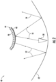
- an antenna 40 includes an antenna main reflector 42 having a shape defining a focal area, and a dual-function antenna structure 44 at the focal area defining a first antenna feed at a first frequency and an antenna subreflector at a second frequency.
- a second antenna feed 50 is operable at the second frequency and cooperates with the antenna subreflector and the antenna main reflector 42.
- the dual-function antenna structure 44 includes a substrate 46 and an array of antenna elements 48 carried thereby.
- the array of antenna elements 48 are advantageously configured so that the dual-function antenna structure 44 provides both an antenna feed at the first frequency and an antenna subreflector at the second frequency without requiring a standalone frequency selective surface (FSS) subreflector as discussed in the background.
- FSS frequency selective surface
- the antenna 40 may be terrestrial, airborne or space-based (e.g., a satellite). When carried by an aircraft, the antenna 40 may be used in the nose of the aircraft, for example.
- the antenna main reflector 42 supports a relatively wide bandwidth, such as 0.5 - 50 GHz, for example. However, a single feed cannot typically cover this entire bandwidth. Instead, two or more antenna feeds are typically used. In the example antenna 40, one antenna feed 50 supports a lower frequency band and the other antenna feed supports a higher frequency band. In other embodiments, an additional antenna feed may be used to support a third frequency band.
- the antenna 40 is thus configured as a dual band reflector antenna supporting two different frequency bands.
- the frequency bands include the low frequency band and the high frequency band.
- the first antenna feed may be configured to support the high frequency band, and the second antenna feed 50 may be configured to support the low frequency band.
- the high frequency band may cover 5 - 50 GHz
- the low frequency band may cover 0.5 - 5 GHz.
- First frequency radio signals 52 generated by the first antenna feed are reflected by the antenna main reflector 42.
- Second frequency radio signals 54 generated by the second antenna feed 50 are reflected by the antenna subreflector which are then reflected by the antenna main reflector 42.
- the second antenna feed 50 functions as a Cassegrain feed.
- the array of antenna elements 48 carried by the substrate 46 operates as a phased array.
- the first antenna feed may be scannable with a beam-forming network coupled to the array of antenna elements 48.
- the antenna elements 48 may be loop antennas, horn antennas, patch antennas, helical antennas, or dipole antennas, for example.
- the second antenna feed 50 may be configured as an array of antenna elements (i.e., a phased array) or as a single antenna element.
- An array element(s) for the second antenna feed 50 may also be a loop antenna, a horn antenna, a patch antenna, a helical antenna or a dipole antenna, for example.
- the dual-function antenna structure 44 advantageously provides a dual-function based on the planar metallization of the array of antenna elements 48 on the curved substrate 46, and based on the capacitive coupling between adjacent antenna elements 48. This allows the array of antenna elements 48 to function as an antenna feed at the first frequency and to function as a subreflector at the second frequency.
- the array of antenna elements 48 may be configured to passively define the antenna subreflector at the second frequency. As noted above, this is inherently based on the planar metallization of the array of antenna elements 48 and the capacitive coupling between adjacent antenna elements 48. This allows the first antenna feed and the second antenna feed 50 to simultaneously operate.
- the array of antenna elements 48 may be configured to actively define the antenna subreflector at the second frequency. As will be described in greater detail below, this is accomplished using a plurality of controllable switches associated with the array of antenna elements 48. Controlling the switches to turn on causes a short between antenna feeds of the antenna elements 48 and between adjacent antenna elements. Consequently, the first antenna feed do not operate when the switches are activated.
- a plot 60 of reflectivity versus frequency for the dual-function antenna structure 44 will be discussed in reference to FIG. 3 .
- the plot 60 corresponds to the array of antenna elements 48 being configured as dipole antenna elements defined in a printed conductive layer.
- the dual-function antenna structure 44 may be referred to as a current sheet array where the electric current is confined to a surface rather than being spread through a volume of space.
- the low frequency band (i.e., first frequency) may cover 0.5 - 5 GHz and the high frequency (i.e., second frequency) band may cover 5 - 50 GHz.
- the dual-function antenna structure 44 operates as the first antenna feed in the high frequency band and the antenna subreflector in the low frequency band.
- the plot 60 of reflectivity versus frequency includes different load conditions of the array of antenna elements 48.
- the different load conditions are provided for vertical polarization and for horizontal polarization.
- the different load conditions include the feeds of the array elements being shorted together, the feeds of the array elements having a normal 50 ohm load, and the feeds of the array elements being open.
- Solid line 62 is for the feeds being shorted together for vertical polarization
- dashed line 64 is for the feeds being shorted together for horizontal polarization
- Solid line 66 is for the feeds being connected to a 50 ohm load for vertical polarization
- dashed line 68 is for the feeds being connected to a 50 ohm load for horizontal polarization.
- the 50 ohm load represents normal operation of the dual-function antenna structure 44.
- Solid line 70 is for the feeds being open for vertical polarization
- dashed line 72 is for the feeds being open for horizontal polarization.
- transition band between 4 - 5 GHz for the dual-function antenna structure 44 operating as the antenna subreflector in the low frequency band and operating as the first antenna feed in the high frequency band.
- the transition band between 4 - 5 GHz may be referred to as a stop band and is not used by the antenna 40.
- controllable switches may be used to short the feeds of the dipole antenna elements and to short the capacitive coupling between adjacent dipole antenna elements. This is a method to actively configure the dual-function antenna structure 44 as the antenna subreflector.
- the use of switches correspond to solid line 62 and dashed line 64 where the feeds are actively shorted together along with the capacitive coupling between adjacent dipole antenna elements. This means the first antenna feed does not operate when the antenna subreflector is operating based on the switches being closed.
- partial schematic diagrams 77, 79 of the array of antenna elements 48 will be discussed.
- the array of antenna elements 48 are shown as dipole antenna elements defined in a printed conductive layer, with the printed conductive layer positioned on a flexible substrate 46.
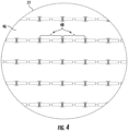
- Partial schematic diagram 77 includes a first set of dipole antenna elements 48 configured to provide singular polarization
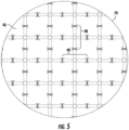
- partial schematic diagram 79 includes first and second sets of dipole antenna elements 48 configured to provide dual polarization.
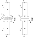
- Example embodiments of the dipole antenna elements 48 are shown in FIGS. 6A and 6B .
- Each dipole antenna element 48 has a medial feed portion 82 and a pair of legs 84 extending outwardly therefrom, with adjacent legs 84 of adjacent dipole antenna elements 48 including respective spaced apart end portions 86 having shapes and relative positioning to provide capacitive coupling between the adjacent dipole antenna elements 48.
- each leg 84 comprises an elongated body portion 89, an enlarged width end portion 91 connected to an end of the elongated body portion, and a plurality of fingers 53, e.g. four, extending outwardly from the enlarged width end portion 91.
- the capacitive coupling provided by interdigitated portions 87 brings broad bandwidth to the antenna by avoiding the resonances associated with individual isolated dipole antennas. Indeed the interdigited portion 87 capacitive coupling causes the array of antenna elements 48 to emulate a continuous sheet of current. Capacitive coupling is measured in ohms of reactance -jx and the required capacitive coupling reactance value in some instances at the lowest frequency of operation may be 100 to 400 ohms in value.
- adjacent legs 84' of adjacent dipole antenna elements may have respective spaced apart end portions 86' to provide increased capacitive coupling between the adjacent dipole antenna elements.
- the spaced apart end portions 86' in adjacent legs 84' comprise enlarged width end portions 91' connected to an end of the elongated body portion 89' to provide the increased capacitive coupling between the adjacent dipole antenna elements.
- enlarged width end portions 91' connected to an end of the elongated body portion 89' to provide the increased capacitive coupling between the adjacent dipole antenna elements.
- other arrangements which increase the capacitive coupling between the adjacent dipole antenna elements may also be possible.
- the array of dipole antenna elements 48 are sized and relatively positioned so that the first antenna feed may be operable over a frequency range of 5 - 50 GHz.
- a size of each dipole antenna element 48 is less than 1/3 of the wavelength of the highest operating frequency.
- the layer 122 may be 2 wavelengths or more in extent.
- controllable switches 90, 92 as now shown in FIG. 7 may be used to operate the dual-function antenna structure 44 as an antenna subreflector at the second frequency.
- Switches 90 are connected across the feeds 82' on adjacent legs 84' of adjacent dipole antenna elements 48.
- Switches 92 are connected across the respective spaced apart end portions 86' between adjacent dipole antenna elements 48.
- the switches may be micro-electromechanical systems (MEMS), for example.
- MEMS micro-electromechanical systems
- a MEMS device may be an electrostatically actuated, micromachined cantilever beam switching element.
- an electrostatic force is generated and it pulls in the movable electrode (actuator).
- actuator Unlike conventional relays an electromagnet is not required.
- the driving voltage becomes OFF, the electrostatic force will disappear, and then the actuator will go back to the original position because of a self-restoring force.
- the MEMS switches may be controlled by high resistance carbon fiber wiring that does not interact with the antenna or associated radio frequency structures.
- Other types of switches may be used in addition to MEMS devices.
- a controller 96 is configured to operate the switches 90, 92. In one embodiment, all of the switches 90, 92 may be operated at the same time. In another embodiment, a selected portion of the switches 90, 92 may be operated. Control wire 101 is connected to switches 90, and control wire 103 is connected to switches 92. To simplify the drawing, the control wires 101, 103 are only shown being connected to one switch each even though each of the switches 90, 92 would have a connection to one of the respective control wires 101, 103. The selected portion of switches may be a portion of only switches 90, or a portion of only switches 92, or a selected combination portion of both switches 90, 92.
- the control wires 101, 103 may be a resistive carbon wire.
- a carbon wire may be less susceptible to RF interference.
- the MEMS devices draw very little electrical current.
- the dual-function antenna structure 44 is based on a current sheet construction since electric current is confined to a surface rather than being spread through a volume of space.
- Upper layer 120 is a dielectric layer used for adjusting impedances between the radio waves and the feeds 82 of the dipole antenna elements 48.
- the feeds 82 of the dipole antenna elements 48 may require lower driving resistances of 50 or 188 ohms yet the impedance of the radio waves is normally 377 ohms. Closely coupled dipole arrays without ground plane reflectors may result in feed gap driving resistances of 377 ohms.
- the upper layer 120 is configured as a sheet of Teflon or light plastic, and may also be referred to as a dielectric matching transformer or a wave matching transformer. Layer 120 is above layer 122 which is the dipole antenna elements 48 carried by the substrate 46.
- artificial dielectrics or metamaterial dielectrics may be used to constitute the upper layer 120, such artificial dielectrics can constitute metal squares on a printed wiring board (PWB).
- Layer 124 is a low dielectric layer with a plurality of openings 130 that are sized to receive the feed organizers 132 shown in layer 126.
- the feed organizers 132 provide signals to and receive signals from the feeds 82 of the dipole antenna elements 48.
- a feed organizer 132 carries four coaxial cables since a pair of dipole antenna elements 48 are orthogonally positioned with respect to one another.
- the dashed corner area corresponds to positioning of one of the feed organizers 132.
- FIG. 9 An enlarged view of a feed organizer 132 without the coaxial cables is provided in FIG. 9
- FIG. 10 An enlarged view of the feed organizer 132 with the coaxial cables 140 is provided in FIG. 10 .
- the feed organizers 132 are positioned between layer 128, which is a ground plane, and layer 122 having the dipole antenna elements 48.
- the feed organizers 132 also help keep unwanted electrical currents such as common mode currents from flowing back down over the outside of the coaxial cables 140.
- Coaxial cables 140 may exhibit the behavior where current can flow back down over the outside of the shield of a coaxial cable 140. By running the coaxial cables 140 through feed organizers 132, this may keep the coaxial cables 140 from having unwanted radiating properties.
- the coaxial cables 140 convey electric currents between the radio frequency electronics and the antenna, but they do not themselves radiate.
- the feed organizers 132 also help keep unwanted electrical currents from flowing back down over the outside of the coaxial cables 140.
- Coaxial cables 140 may exhibit the behavior where current can flow back down over the outside of the shield of a coaxial cable 140. By running the coaxial cables 140 through feed organizers 132, this may keep the coaxial cables 140 from having unwanted radiating properties.
- the coaxial cables 140 deliver electric control signals, but they do not themselves radiate.
- the current sheet arrangement may also be referred to as a differential feed current sheet.
- Each of the coaxial cables 140 in the feed organizers 132 are successive in phase: 0°, 90°, 180° and 270°. This may also be referred to as phase quadrature.
- the coaxial cables 140 may all have the same power so they are equal in amplitude. Pairs of the coaxial cables 140 may act as two electrical current sources in series with each other usefully halving the driving resistances of the feeds 132.
- Another aspect is directed to a method for making a dual-function antenna structure 44 to be positioned at a focal area of a main reflector 42.
- the main reflector 42 has a second antenna feed 50 associated therewith and is operable at a second frequency.
- the method includes forming an array of antenna elements 48 on a substrate 46 to define a first antenna feed at a first frequency and an antenna subreflector at the second frequency.
- FIG. 11 another aspect of the present description is directed to a system 220 to be carried by a vehicle 200, such as an aircraft.
- vehicle 200 such as an aircraft.
- the vehicle 200 may be land-based, water-based or space-based.
- the system 200 includes a dual-function antenna structure 244, a beam forming network 251, a radar detector 261, a controller 271, and communication circuitry 280. Certain reference numbers as used above will also be used below but will be preceded by a 2 to refer to like elements.
- the dual-function antenna structure 244 is operable between a steerable phased array communication mode and a low radar cross section (RCS) mode.
- RCS radar cross section
- communication signals may be transmitted and/or received by the dual-function antenna structure 244.
- a radar cross section of the dual-function antenna structure 244 is reduced in order to be less detectable by radar. Communication signals are not transmitted or received by the dual-function antenna structure 244 in the low RCS mode.
- the beam forming network 251 is coupled to the dual-function antenna structure 244 and to the communication circuitry 280.
- the radar detector 261 is configured to detect radar signals being directed to the vehicle 200.
- the controller 271 is configured to control the dual-function antenna structure 244 to switch between the steerable phased array communication mode and the low RCS mode responsive to the radar detector 261 detecting radar signals.
- the radar detector 261 may be external the vehicle 200 but is in communications with the controller 271.
- the dual-function antenna structure 244 includes a substrate 246 and an array of antenna elements 248 carried thereby.
- the antenna elements 248 may be dipole antenna elements defined in a printed conductive layer, with the printed conductive layer positioned on a flexible substrate 246.
- the antenna elements 48 may be sized to operate within the UHF frequency range (0.3 - 3 GHz), for example.
- the dipole antenna elements 248 may include a first set of dipole antenna elements configured to provide singular polarization (as shown in FIG. 4 ), or to include first and second sets of dipole antenna elements configured to provide dual polarization (as shown in FIG. 5 ).
- the dual-function antenna structure 244 has different radar cross section (RCS) antenna patterns 230, 232 depending on how the feeds of the dipole antenna elements 248 are being loaded.
- the beam forming network 251 includes controllable phase shifters 252 for steering an antenna beam by adjusting the phase of the dipole antenna elements 248.
- the beam forming network 251 also includes an impedance matching network 254 for matching input impedances of the dipole antenna elements 248 with the output impedances of RF circuitry (e.g., power amplifiers) used to drive the dipole antenna elements 248.
- RF circuitry e.g., power amplifiers
- the RCS antenna patterns 230, 232 are generated in response radar signals 217 being received by the dual-function antenna structure 244 from a radar 215. Reflection of incident radar signals 217 received by the dual-function antenna structure 244 varies between the different RCS antenna patterns 230, 232.
- Antenna pattern 230 will be referred to as an antenna mode RCS scattering pattern, and antenna pattern 232 will be referred to as a structural mode RCS scattering pattern.
- the antenna mode RCS scattering pattern 230 corresponds to when the dual-function antenna structure 244 is in the steerable phased array communication mode. In this mode, the feeds of the dipole antenna elements 248 are connected to a 50 ohm load.
- the antenna mode RCS scattering pattern 230 has a broad pattern, which typically results in a broad glint (i.e., strong response) being displayed on a radar display. This makes it easier for the radar 215 to receive signals reflected by the dual-function antenna structure 244.
- the structural antenna mode RCS pattern 232 corresponds to when the dual-function antenna structure 244 is in the low RCS mode. In the low RCS mode, the feeds of the dipole antenna elements 248 are shorted together.
- the structural antenna mode RCS pattern 232 has a narrow beam, which typically results in a small blip being displayed on a radar display. This makes it harder for the radar 215 to receive signals reflected by the dual-function antenna structure 244.
- one approach for switching the dual-function antenna structure 244 to the low RCS mode is based on controllable switches 290, 292, as shown in FIG. 13 .
- Controlling the switches 290, 292 to turn on causes a short between feeds 282 of the antenna elements 248 and between ends of adjacent antenna elements 286.
- the dual-function antenna structure 244 functions as a metal plate when the switches 290, 292 are closed.
- the narrow structural mode RCS scattering pattern 232 is present instead of the broad antenna mode RCS scattering pattern 230.
- Switches 290 are connected across the feeds 282 on adjacent legs 284 of adjacent dipole antenna elements 248.
- Switches 292 are connected across the respective spaced apart end portions 286 between adjacent dipole antenna elements 248.
- the switches 290, 292 may be micro-electromechanical systems (MEMS) devices, for example.
- MEMS micro-electromechanical systems
- the controller 271 is configured to operate the switches 290, 292 in response to the radar detector 261 detecting radar signals being directed towards the vehicle 200.
- Control wire 275 is used to close the switches 290, 292 at the same time.
- another approach for switching the dual-function antenna structure 244' to the low RCS mode is based on control of the phase shifters 252' in the beam forming network 251'.
- the impedance matching network 254' is used to control the phase shifters 252' so that a phase of the structural mode RCS scattering pattern 232 is 180 degrees out of phase with the antenna mode RCS scattering pattern 230.
- RCS mode parameters 272' of the impedance matching network 254' are determined ahead of time based on computation analysis.
- the RCS mode parameters 272' may be stored in the controller 271', as shown, or in the beam forming network 251'.
- ⁇ total ⁇ SC + ⁇ RL
- the total reflectivity value ⁇ total takes into account all contributing factors in the radar return.
- ⁇ SC represents the radar cross section of the dual-function antenna structure 244' when there is a short between feeds 282' of the antenna elements 248' and between adjacent antenna elements 286'. This corresponds to the antenna mode RCS scattering pattern 230.
- the amplitude and phase of the scattered return is measured in the frequency domain using a network analyzer. Phase ⁇ is on the x-axis and amplitude ⁇ is on the y-axis.
- the value ⁇ RL represents the radar cross section of the dual-function antenna structure 244' when the feeds 282' of the antenna elements 248' have a maximum power transfer loading impedance. This corresponds to the structural mode RCS scattering pattern 232. The amplitude and phase of the scattered return is also measured in the frequency domain using a network analyzer.
- the beam forming network 251' includes an impedance matching network 254', which may also be referred to as an impedance transformer.
- the impedance matching network 254' is used to create a matched impedance between the power amplifiers in the communication circuitry 280' and the dipole antenna elements 248'.
- the impedance matching network 254' is well suited to operate a large number of regularly spaced dipole antenna elements 248'.
- the maximum power transfer loading impedance is typically 50 ohms by convention. If the system 220' deviates from convention then the: 1) antenna radiation resistance is equal to the resistive component of the circuit loading impedance, and the 2) reactive component of the antenna impedance is the complex conjugate of the circuit loading impedance (e.g., if the dipole antenna elements 248' are capacitive then the load impedance needs to be proportionally inductive).
- variable ⁇ equals an amplitude response of the impedance matching network 254' associated with a dipole antenna element 248'.
- the variable ⁇ equals a phase response of the impedance matching network 254' associated with the same dipole antenna element 248'.
- the impedance matching network 254' may be controlled so that a phase of ⁇ SC (structural mode RCS scattering pattern 232 ) is out of phase with ⁇ RL (antenna mode RCS scattering pattern 230 ).
- the determined amplitude ⁇ and phase ⁇ values define the RCS mode parameters 272'. Consequently, when the dual-function antenna structure 244' is switched to the low RCS mode, the computed amplitude ⁇ and phase values ⁇ for the impedance matching network 252' are used.
- the radar 215 does may not see a radar return or backscatter from the dual-function antenna structure 244'.
- the radar 215 may see a reduced radar return or backscatter from the dual-function antenna structure 244'. Also, the reduced radar pattern resulting from the structural and antenna mode cancellation will vary in magnitude as a function of look angle, frequency and polarization.
- the dual-function antenna structure 244' When the dual-function antenna structure 244' is in the nose of an aircraft, for example, the dual-function antenna structure 244' may be curved.
- a curved surface antenna will have a low structural radar cross section over a large range of look angles while a flat surface antenna will have a high structure radar cross section over a narrow range of look angles.
- Another aspect is directed to a method for operating a system 220 to be carried by a vehicle 200, with the system 220 comprising a dual-function antenna structure 244 that includes a substrate 246 and an array of antenna elements 248 carried thereby, and a beam forming network 251 coupled to the dual-function antenna structure 244.
- the method may comprise controlling the dual-function antenna structure 244 to switch between a steerable phased array communication mode and a low radar cross section (RCS) mode responsive to a radar detector 261 detecting radar signals being directed to the vehicle 200.
- RCS radar cross section
Landscapes
- Engineering & Computer Science (AREA)
- Remote Sensing (AREA)
- Physics & Mathematics (AREA)
- General Physics & Mathematics (AREA)
- Radar, Positioning & Navigation (AREA)
- Computer Networks & Wireless Communication (AREA)
- Astronomy & Astrophysics (AREA)
- Aviation & Aerospace Engineering (AREA)
- Variable-Direction Aerials And Aerial Arrays (AREA)
Abstract
A system to be carried by a vehicle may include a dual-function antenna structure that includes a substrate and an array of antenna elements carried thereby. A beam forming network may be coupled to the dual-function antenna structure. A radar detector to be carried by the vehicle may be configured to detect radar signals directed to the vehicle. A controller may be configured to control the dual-function antenna structure to switch between a steerable phased array communication mode and a low radar cross section (RCS) mode responsive to the radar detector.
Description
- The present disclosure relates to systems, and, more particularly, to a steerable phased array antenna and associated methods.
- Radar cross-section (RCS) is a measure of how detectable an object is by radar. Certain vehicles, such as aircraft, may be designed to have low detectability. These aircraft may have, for example, a combination of absorbent paint and angled surfaces to reflect a radar signal somewhere other than towards the source.
- Aircraft antennas can have many different shapes and sizes. Traditionally, antennas may be formed more for their function, and their shape and placement are usually determined by their directional qualities and the frequencies they use to operate. When an antenna is placed in the nose of an aircraft, for example, radar signals may be undesirably reflected by the antenna back towards the source.
- The aircraft antennas may operate as maximum power transfer devices where the source resistance is equal to the load resistance. Some receive antennas may reradiate 50 percent of the incident power and convey 50 percent of incident back into the receiving system less dissipative losses.
- A system to be carried by a vehicle may comprise a dual-function antenna structure that includes a substrate and an array of antenna elements carried thereby, a beam forming network coupled to the dual-function antenna structure, and a radar detector to be carried by the vehicle and configured to detect radar signals directed to the vehicle. The controller may be configured to control the dual-function antenna structure to switch between a steerable phased array communication mode and a low radar cross section (RCS) mode responsive to the radar detector.
- The dual-function antenna structure may comprise a plurality of controllable switches associated with the array of antenna elements and coupled to the controller.
- The beam forming network may comprise a plurality of controllable phase shifters coupled to the controller. The controller may be configured to operate the plurality of controllable phase shifters in the steerable phased array communication mode and in the low RCS communication mode.
- The system may comprise communication circuitry coupled to the dual-function antenna structure. The array of antenna elements may comprise an array of dipole antenna elements. Each dipole antenna element may comprise a medial feed portion and a pair of legs extending outwardly therefrom, with adjacent legs of adjacent dipole antenna elements including respective spaced apart end portions having shapes and relative positioning to provide capacitive coupling between the adjacent dipole antenna elements.
- The dual-function antenna structure may comprise a plurality of controllable switches associated with the array of antenna elements and coupled to the controller. The plurality of controllable switches may comprise a first set of controllable switches configured to couple together the medial feed portions of the dipole antenna elements, and a second set of controllable switches configured to couple together the adjacent end portions of the dipole antenna elements.
- Each leg may comprise an elongated body portion and an enlarged width end portions connected thereto. The spaced apart end portions in adjacent legs may comprise interdigitated portions.
- The array of antenna elements may comprise a first set of dipole antenna elements to provide singular polarization. In other embodiments, the array of antenna elements may comprise first and second sets of orthogonal antenna elements to provide dual polarization.
- Another aspect is directed to a system to be carried by a vehicle and comprising a dual-function antenna structure that includes a substrate and an array of antenna elements carried thereby, and a beam forming network coupled to the dual-function antenna structure. A controller may be configured to control the dual-function antenna structure to switch between a steerable phased array communication mode and a low radar cross section (RCS) mode responsive to a radar detector carried by the vehicle detecting radar signals directed to the vehicle.
- A method for operating a system to be carried by a vehicle, with the system comprising a dual-function antenna structure that includes a substrate and an array of antenna elements carried thereby, and a beam forming network coupled to the dual-function antenna structure. The method may comprise controlling the dual-function antenna structure to switch between a steerable phased array communication mode and a low radar cross section (RCS) mode responsive to a radar detector carried by the vehicle detecting radar signals being directed to the vehicle.
-
-
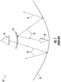
FIG. 1 is a schematic diagram of an antenna with a frequency selective surface (FSS) subreflector as in the prior art. -
FIG. 2 is a schematic diagram of an antenna with a dual-function antenna structure of the invention. -
FIG. 3 is a plot of reflectivity versus frequency for the dual-function antenna structure as illustrated inFIG. 2 . -
FIG. 4 is a partial schematic diagram of the array of antenna elements illustrated inFIG. 2 shown as dipole antenna elements and configured to provide singular polarization. -
FIG. 5 is a partial schematic diagram of the array of antenna elements illustrated inFIG. 2 shown as dipole antenna elements and configured to provide dual polarization. -
FIGS. 6A and 6B are example embodiments of the dipole antenna elements illustrated inFIGS. 4 and5 , respectively. -
FIG. 7 is a partial schematic diagram of the dipole antenna elements illustrated inFIG. 5 with controllable switches associated therewith. -
FIG. 8 is an exploded schematic view of the dual-function antenna structure illustrated inFIG. 2 . -
FIG. 9 is an enlarged view of one of the feed organizers illustrated inFIG. 8 . -
FIG. 10 is an enlarged view of one of the feed organizers illustrated inFIG. 8 with coaxial cables positioned therein. -
FIG. 11 is a schematic diagram of a system carried by a vehicle that includes another embodiment of the dual-function antenna structure of the invention. -
FIG. 12 is a plot of different radar return antenna patterns for the dual-function antenna structure illustrated inFIG. 11 . -
FIG. 13 is a detailed schematic diagram of the system illustrated inFIG. 11 for one embodiment of placing the dual-function antenna structure in a low RCS mode. -
FIG. 14 is a detailed schematic diagram of the system illustrated inFIG. 11 for another embodiment of placing the dual-function antenna structure in a low RCS mode. - The present description is made with reference to the accompanying drawings, in which exemplary embodiments are shown. However, many different embodiments may be used, and thus the description should not be construed as limited to the particular embodiments set forth herein. Rather, these embodiments are provided so that this disclosure will be thorough and complete. Like numbers refer to like elements throughout, and prime notations may be used to indicate similar elements in different embodiments.
- Referring initially to
FIG. 2 , anantenna 40 includes an antennamain reflector 42 having a shape defining a focal area, and a dual-function antenna structure 44 at the focal area defining a first antenna feed at a first frequency and an antenna subreflector at a second frequency. Asecond antenna feed 50 is operable at the second frequency and cooperates with the antenna subreflector and the antennamain reflector 42. - The dual-
function antenna structure 44 includes asubstrate 46 and an array ofantenna elements 48 carried thereby. The array ofantenna elements 48 are advantageously configured so that the dual-function antenna structure 44 provides both an antenna feed at the first frequency and an antenna subreflector at the second frequency without requiring a standalone frequency selective surface (FSS) subreflector as discussed in the background. - The
antenna 40 may be terrestrial, airborne or space-based (e.g., a satellite). When carried by an aircraft, theantenna 40 may be used in the nose of the aircraft, for example. The antennamain reflector 42 supports a relatively wide bandwidth, such as 0.5 - 50 GHz, for example. However, a single feed cannot typically cover this entire bandwidth. Instead, two or more antenna feeds are typically used. In theexample antenna 40, oneantenna feed 50 supports a lower frequency band and the other antenna feed supports a higher frequency band. In other embodiments, an additional antenna feed may be used to support a third frequency band. - The
antenna 40 is thus configured as a dual band reflector antenna supporting two different frequency bands. The frequency bands include the low frequency band and the high frequency band. The first antenna feed may be configured to support the high frequency band, and thesecond antenna feed 50 may be configured to support the low frequency band. For illustration purposes, the high frequency band may cover 5 - 50 GHz, and the low frequency band may cover 0.5 - 5 GHz. - First frequency radio signals 52 generated by the first antenna feed are reflected by the antenna
main reflector 42. Second frequency radio signals 54 generated by thesecond antenna feed 50 are reflected by the antenna subreflector which are then reflected by the antennamain reflector 42. The second antenna feed 50 functions as a Cassegrain feed. - The array of
antenna elements 48 carried by thesubstrate 46 operates as a phased array. In some embodiments, the first antenna feed may be scannable with a beam-forming network coupled to the array ofantenna elements 48. - The
antenna elements 48 may be loop antennas, horn antennas, patch antennas, helical antennas, or dipole antennas, for example. Thesecond antenna feed 50 may be configured as an array of antenna elements (i.e., a phased array) or as a single antenna element. An array element(s) for thesecond antenna feed 50 may also be a loop antenna, a horn antenna, a patch antenna, a helical antenna or a dipole antenna, for example. - As will be described in greater detail below, the dual-
function antenna structure 44 advantageously provides a dual-function based on the planar metallization of the array ofantenna elements 48 on thecurved substrate 46, and based on the capacitive coupling betweenadjacent antenna elements 48. This allows the array ofantenna elements 48 to function as an antenna feed at the first frequency and to function as a subreflector at the second frequency. - In one embodiment, the array of
antenna elements 48 may be configured to passively define the antenna subreflector at the second frequency. As noted above, this is inherently based on the planar metallization of the array ofantenna elements 48 and the capacitive coupling betweenadjacent antenna elements 48. This allows the first antenna feed and thesecond antenna feed 50 to simultaneously operate. - In another embodiment, the array of
antenna elements 48 may be configured to actively define the antenna subreflector at the second frequency. As will be described in greater detail below, this is accomplished using a plurality of controllable switches associated with the array ofantenna elements 48. Controlling the switches to turn on causes a short between antenna feeds of theantenna elements 48 and between adjacent antenna elements. Consequently, the first antenna feed do not operate when the switches are activated. - A
plot 60 of reflectivity versus frequency for the dual-function antenna structure 44 will be discussed in reference toFIG. 3 . Theplot 60 corresponds to the array ofantenna elements 48 being configured as dipole antenna elements defined in a printed conductive layer. As will be discussed in greater detail below, the dual-function antenna structure 44 may be referred to as a current sheet array where the electric current is confined to a surface rather than being spread through a volume of space. - As noted above, the low frequency band (i.e., first frequency) may cover 0.5 - 5 GHz and the high frequency (i.e., second frequency) band may cover 5 - 50 GHz. The dual-
function antenna structure 44 operates as the first antenna feed in the high frequency band and the antenna subreflector in the low frequency band. - The
plot 60 of reflectivity versus frequency includes different load conditions of the array ofantenna elements 48. The different load conditions are provided for vertical polarization and for horizontal polarization. The different load conditions include the feeds of the array elements being shorted together, the feeds of the array elements having a normal 50 ohm load, and the feeds of the array elements being open. -
Solid line 62 is for the feeds being shorted together for vertical polarization, and dashedline 64 is for the feeds being shorted together for horizontal polarization.Solid line 66 is for the feeds being connected to a 50 ohm load for vertical polarization, and dashedline 68 is for the feeds being connected to a 50 ohm load for horizontal polarization. The 50 ohm load represents normal operation of the dual-function antenna structure 44.Solid line 70 is for the feeds being open for vertical polarization, and dashedline 72 is for the feeds being open for horizontal polarization. - There is a transition band between 4 - 5 GHz for the dual-
function antenna structure 44 operating as the antenna subreflector in the low frequency band and operating as the first antenna feed in the high frequency band. The transition band between 4 - 5 GHz may be referred to as a stop band and is not used by theantenna 40. -
Solid line 66 and dashedline 68 represent normal operation of the dual-function antenna structure 44. In passive operation, the transition between the antenna subreflector and the first antenna feed is passively achieved. This is based on the planar metallization of the array ofantenna elements 48 and the capacitive coupling betweenadjacent antenna elements 48 on the printed conductive layer. Passive operation of the dual-function antenna structure 44 allows the first antenna feed and thesecond antenna feed 50 to simultaneously operate. - To minimize or reduce the transition band, controllable switches may be used to short the feeds of the dipole antenna elements and to short the capacitive coupling between adjacent dipole antenna elements. This is a method to actively configure the dual-
function antenna structure 44 as the antenna subreflector. The use of switches correspond tosolid line 62 and dashedline 64 where the feeds are actively shorted together along with the capacitive coupling between adjacent dipole antenna elements. This means the first antenna feed does not operate when the antenna subreflector is operating based on the switches being closed. - Referring now to
FIGS. 4 and5 , partial schematic diagrams 77, 79 of the array ofantenna elements 48 will be discussed. The array ofantenna elements 48 are shown as dipole antenna elements defined in a printed conductive layer, with the printed conductive layer positioned on aflexible substrate 46. Partial schematic diagram 77 includes a first set ofdipole antenna elements 48 configured to provide singular polarization, whereas partial schematic diagram 79 includes first and second sets ofdipole antenna elements 48 configured to provide dual polarization. - Example embodiments of the
dipole antenna elements 48 are shown inFIGS. 6A and 6B . Eachdipole antenna element 48 has amedial feed portion 82 and a pair oflegs 84 extending outwardly therefrom, withadjacent legs 84 of adjacentdipole antenna elements 48 including respective spaced apart endportions 86 having shapes and relative positioning to provide capacitive coupling between the adjacentdipole antenna elements 48. - As shown in
FIG. 6A , the spaced apart endportions 86 inadjacent legs 84 have overlapping orinterdigitated portions 87. Eachleg 84 comprises anelongated body portion 89, an enlargedwidth end portion 91 connected to an end of the elongated body portion, and a plurality offingers 53, e.g. four, extending outwardly from the enlargedwidth end portion 91. - The capacitive coupling provided by
interdigitated portions 87 brings broad bandwidth to the antenna by avoiding the resonances associated with individual isolated dipole antennas. Indeed theinterdigited portion 87 capacitive coupling causes the array ofantenna elements 48 to emulate a continuous sheet of current. Capacitive coupling is measured in ohms of reactance -jx and the required capacitive coupling reactance value in some instances at the lowest frequency of operation may be 100 to 400 ohms in value. - Alternatively, as shown in
FIG. 6B ,adjacent legs 84' of adjacent dipole antenna elements may have respective spaced apart endportions 86' to provide increased capacitive coupling between the adjacent dipole antenna elements. In this embodiment, the spaced apart endportions 86' inadjacent legs 84' comprise enlarged width end portions 91' connected to an end of the elongated body portion 89' to provide the increased capacitive coupling between the adjacent dipole antenna elements. Of course other arrangements which increase the capacitive coupling between the adjacent dipole antenna elements may also be possible. - The array of
dipole antenna elements 48 are sized and relatively positioned so that the first antenna feed may be operable over a frequency range of 5 - 50 GHz. Preferably, a size of eachdipole antenna element 48 is less than 1/3 of the wavelength of the highest operating frequency. At the lowest operating frequency thelayer 122 may be 2 wavelengths or more in extent. - As discussed above,
controllable switches FIG. 7 may be used to operate the dual-function antenna structure 44 as an antenna subreflector at the second frequency.Switches 90 are connected across thefeeds 82' onadjacent legs 84' of adjacentdipole antenna elements 48.Switches 92 are connected across the respective spaced apart endportions 86' between adjacentdipole antenna elements 48. - The switches may be micro-electromechanical systems (MEMS), for example. A MEMS device may be an electrostatically actuated, micromachined cantilever beam switching element. When applying a voltage between a fixed electrode and a movable electrode, an electrostatic force is generated and it pulls in the movable electrode (actuator). Unlike conventional relays an electromagnet is not required. When the driving voltage becomes OFF, the electrostatic force will disappear, and then the actuator will go back to the original position because of a self-restoring force. As little electric current flow is required by the MEMS switches they may be controlled by high resistance carbon fiber wiring that does not interact with the antenna or associated radio frequency structures. Other types of switches may be used in addition to MEMS devices.
- A
controller 96 is configured to operate theswitches switches switches Control wire 101 is connected toswitches 90, andcontrol wire 103 is connected to switches 92. To simplify the drawing, thecontrol wires switches respective control wires switches - The
control wires - Referring now to
FIG. 8 , an exploded view of the dual-function antenna structure 44 will be discussed. The dual-function antenna structure 44 is based on a current sheet construction since electric current is confined to a surface rather than being spread through a volume of space. -
Upper layer 120 is a dielectric layer used for adjusting impedances between the radio waves and thefeeds 82 of thedipole antenna elements 48. Thefeeds 82 of thedipole antenna elements 48 may require lower driving resistances of 50 or 188 ohms yet the impedance of the radio waves is normally 377 ohms. Closely coupled dipole arrays without ground plane reflectors may result in feed gap driving resistances of 377 ohms. Theupper layer 120 is configured as a sheet of Teflon or light plastic, and may also be referred to as a dielectric matching transformer or a wave matching transformer.Layer 120 is abovelayer 122 which is thedipole antenna elements 48 carried by thesubstrate 46. In some instances artificial dielectrics or metamaterial dielectrics may be used to constitute theupper layer 120, such artificial dielectrics can constitute metal squares on a printed wiring board (PWB). -
Layer 124 is a low dielectric layer with a plurality ofopenings 130 that are sized to receive thefeed organizers 132 shown inlayer 126. Thefeed organizers 132 provide signals to and receive signals from thefeeds 82 of thedipole antenna elements 48. For dual polarization, afeed organizer 132 carries four coaxial cables since a pair ofdipole antenna elements 48 are orthogonally positioned with respect to one another. The dashed corner area corresponds to positioning of one of thefeed organizers 132. - An enlarged view of a
feed organizer 132 without the coaxial cables is provided inFIG. 9 , and an enlarged view of thefeed organizer 132 with thecoaxial cables 140 is provided inFIG. 10 . Thefeed organizers 132 are positioned betweenlayer 128, which is a ground plane, andlayer 122 having thedipole antenna elements 48. - The
feed organizers 132 also help keep unwanted electrical currents such as common mode currents from flowing back down over the outside of thecoaxial cables 140.Coaxial cables 140 may exhibit the behavior where current can flow back down over the outside of the shield of acoaxial cable 140. By running thecoaxial cables 140 throughfeed organizers 132, this may keep thecoaxial cables 140 from having unwanted radiating properties. Thecoaxial cables 140 convey electric currents between the radio frequency electronics and the antenna, but they do not themselves radiate. - The
feed organizers 132 also help keep unwanted electrical currents from flowing back down over the outside of thecoaxial cables 140.Coaxial cables 140 may exhibit the behavior where current can flow back down over the outside of the shield of acoaxial cable 140. By running thecoaxial cables 140 throughfeed organizers 132, this may keep thecoaxial cables 140 from having unwanted radiating properties. Thecoaxial cables 140 deliver electric control signals, but they do not themselves radiate. - The current sheet arrangement may also be referred to as a differential feed current sheet. Each of the
coaxial cables 140 in thefeed organizers 132 are successive in phase: 0°, 90°, 180° and 270°. This may also be referred to as phase quadrature. Thecoaxial cables 140 may all have the same power so they are equal in amplitude. Pairs of thecoaxial cables 140 may act as two electrical current sources in series with each other usefully halving the driving resistances of thefeeds 132. - Another aspect is directed to a method for making a dual-
function antenna structure 44 to be positioned at a focal area of amain reflector 42. Themain reflector 42 has asecond antenna feed 50 associated therewith and is operable at a second frequency. The method includes forming an array ofantenna elements 48 on asubstrate 46 to define a first antenna feed at a first frequency and an antenna subreflector at the second frequency. - Referring now to
FIG. 11 , another aspect of the present description is directed to asystem 220 to be carried by avehicle 200, such as an aircraft. In addition to thevehicle 200 being an airborne vehicle, thevehicle 200 may be land-based, water-based or space-based. - The
system 200 includes a dual-function antenna structure 244, abeam forming network 251, aradar detector 261, acontroller 271, andcommunication circuitry 280. Certain reference numbers as used above will also be used below but will be preceded by a 2 to refer to like elements. - The dual-
function antenna structure 244 is operable between a steerable phased array communication mode and a low radar cross section (RCS) mode. In the steerable phased array communication mode, communication signals may be transmitted and/or received by the dual-function antenna structure 244. In the low RCS mode, a radar cross section of the dual-function antenna structure 244 is reduced in order to be less detectable by radar. Communication signals are not transmitted or received by the dual-function antenna structure 244 in the low RCS mode. - The
beam forming network 251 is coupled to the dual-function antenna structure 244 and to thecommunication circuitry 280. Theradar detector 261 is configured to detect radar signals being directed to thevehicle 200. Thecontroller 271 is configured to control the dual-function antenna structure 244 to switch between the steerable phased array communication mode and the low RCS mode responsive to theradar detector 261 detecting radar signals. In other embodiments, theradar detector 261 may be external thevehicle 200 but is in communications with thecontroller 271. - The dual-
function antenna structure 244 includes asubstrate 246 and an array ofantenna elements 248 carried thereby. Theantenna elements 248 may be dipole antenna elements defined in a printed conductive layer, with the printed conductive layer positioned on aflexible substrate 246. Theantenna elements 48 may be sized to operate within the UHF frequency range (0.3 - 3 GHz), for example. Thedipole antenna elements 248 may include a first set of dipole antenna elements configured to provide singular polarization (as shown inFIG. 4 ), or to include first and second sets of dipole antenna elements configured to provide dual polarization (as shown inFIG. 5 ). - Referring now to
FIGS. 12-14 , the dual-function antenna structure 244 has different radar cross section (RCS)antenna patterns dipole antenna elements 248 are being loaded. Thebeam forming network 251 includescontrollable phase shifters 252 for steering an antenna beam by adjusting the phase of thedipole antenna elements 248. Thebeam forming network 251 also includes animpedance matching network 254 for matching input impedances of thedipole antenna elements 248 with the output impedances of RF circuitry (e.g., power amplifiers) used to drive thedipole antenna elements 248. - The
RCS antenna patterns function antenna structure 244 from aradar 215. Reflection of incident radar signals 217 received by the dual-function antenna structure 244 varies between the differentRCS antenna patterns Antenna pattern 230 will be referred to as an antenna mode RCS scattering pattern, andantenna pattern 232 will be referred to as a structural mode RCS scattering pattern. - The antenna mode
RCS scattering pattern 230 corresponds to when the dual-function antenna structure 244 is in the steerable phased array communication mode. In this mode, the feeds of thedipole antenna elements 248 are connected to a 50 ohm load. The antenna modeRCS scattering pattern 230 has a broad pattern, which typically results in a broad glint (i.e., strong response) being displayed on a radar display. This makes it easier for theradar 215 to receive signals reflected by the dual-function antenna structure 244. - The structural antenna
mode RCS pattern 232 corresponds to when the dual-function antenna structure 244 is in the low RCS mode. In the low RCS mode, the feeds of thedipole antenna elements 248 are shorted together. The structural antennamode RCS pattern 232 has a narrow beam, which typically results in a small blip being displayed on a radar display. This makes it harder for theradar 215 to receive signals reflected by the dual-function antenna structure 244. - In
system 220, one approach for switching the dual-function antenna structure 244 to the low RCS mode is based oncontrollable switches FIG. 13 . Controlling theswitches feeds 282 of theantenna elements 248 and between ends ofadjacent antenna elements 286. The dual-function antenna structure 244 functions as a metal plate when theswitches RCS scattering pattern 232 is present instead of the broad antenna modeRCS scattering pattern 230. -
Switches 290 are connected across thefeeds 282 onadjacent legs 284 of adjacentdipole antenna elements 248.Switches 292 are connected across the respective spaced apart endportions 286 between adjacentdipole antenna elements 248. As noted above, theswitches - The
controller 271 is configured to operate theswitches radar detector 261 detecting radar signals being directed towards thevehicle 200.Control wire 275 is used to close theswitches - In system 220', another approach for switching the dual-function antenna structure 244' to the low RCS mode is based on control of the phase shifters 252' in the beam forming network 251'. The impedance matching network 254' is used to control the phase shifters 252' so that a phase of the structural mode
RCS scattering pattern 232 is 180 degrees out of phase with the antenna modeRCS scattering pattern 230.RCS mode parameters 272' of the impedance matching network 254' are determined ahead of time based on computation analysis. TheRCS mode parameters 272' may be stored in the controller 271', as shown, or in the beam forming network 251'. - The computation analysis includes determining the total radar return σtotal of the dual-function antenna structure 244', which is based on the following equation:

- The value of σSC represents the radar cross section of the dual-function antenna structure 244' when there is a short between feeds 282' of the antenna elements 248' and between adjacent antenna elements 286'. This corresponds to the antenna mode
RCS scattering pattern 230. The amplitude and phase of the scattered return is measured in the frequency domain using a network analyzer. Phase β is on the x-axis and amplitude α is on the y-axis. - The value σRL represents the radar cross section of the dual-function antenna structure 244' when the feeds 282' of the antenna elements 248' have a maximum power transfer loading impedance. This corresponds to the structural mode
RCS scattering pattern 232. The amplitude and phase of the scattered return is also measured in the frequency domain using a network analyzer. - The beam forming network 251' includes an impedance matching network 254', which may also be referred to as an impedance transformer. The impedance matching network 254' is used to create a matched impedance between the power amplifiers in the communication circuitry 280' and the dipole antenna elements 248'. The impedance matching network 254' is well suited to operate a large number of regularly spaced dipole antenna elements 248'.
- The maximum power transfer loading impedance is typically 50 ohms by convention. If the system 220' deviates from convention then the: 1) antenna radiation resistance is equal to the resistive component of the circuit loading impedance, and the 2) reactive component of the antenna impedance is the complex conjugate of the circuit loading impedance (e.g., if the dipole antenna elements 248' are capacitive then the load impedance needs to be proportionally inductive).
- The total radar return σtotal of the dual-
function antenna structure 244 may now be written to include the reflection coefficient gamma Γ of the impedance matching network 254' :
- The impedance matching network 254' is based on the following equation, where f is a function to be determined by measurement.

- The variable α equals an amplitude response of the impedance matching network 254' associated with a dipole antenna element 248'. The variable β equals a phase response of the impedance matching network 254' associated with the same dipole antenna element 248'.
- The impedance matching network 254' may be controlled so that a phase of σSC (structural mode RCS scattering pattern 232) is out of phase with σRL (antenna mode RCS scattering pattern 230).
RCS mode parameters 272' of the impedance matching network 254' needed for the beam forming network 251' to operate in the low RCS mode may be determined based on the phases of σSC and σRL adding to 0:
- The above equation may be arranged as follows:

- The amplitude α and phase β of the phase shifters 252' may now be determined as follows:

- The determined amplitude α and phase β values define the
RCS mode parameters 272'. Consequently, when the dual-function antenna structure 244' is switched to the low RCS mode, the computed amplitude α and phase values β for the impedance matching network 252' are used. - Once the impedance matching network 254' is determined so that the phase of the structural mode
RCS scattering pattern 232 is 180 degrees out of phase with the antenna modeRCS scattering pattern 230, then theradar 215 does may not see a radar return or backscatter from the dual-function antenna structure 244'. - However, when the phase of the structural mode
RCS scattering pattern 232 and the phase of the antenna modeRCS scattering pattern 230 are not completely cancelled, then theradar 215 may see a reduced radar return or backscatter from the dual-function antenna structure 244'. Also, the reduced radar pattern resulting from the structural and antenna mode cancellation will vary in magnitude as a function of look angle, frequency and polarization. - When the dual-function antenna structure 244' is in the nose of an aircraft, for example, the dual-function antenna structure 244' may be curved. A curved surface antenna will have a low structural radar cross section over a large range of look angles while a flat surface antenna will have a high structure radar cross section over a narrow range of look angles.
- Another aspect is directed to a method for operating a
system 220 to be carried by avehicle 200, with thesystem 220 comprising a dual-function antenna structure 244 that includes asubstrate 246 and an array ofantenna elements 248 carried thereby, and abeam forming network 251 coupled to the dual-function antenna structure 244. The method may comprise controlling the dual-function antenna structure 244 to switch between a steerable phased array communication mode and a low radar cross section (RCS) mode responsive to aradar detector 261 detecting radar signals being directed to thevehicle 200. - Many modifications and other embodiments will come to the mind of one skilled in the art having the benefit of the teachings presented in the foregoing descriptions and the associated drawings. Therefore, it is understood that the foregoing is not to be limited to the example embodiments, and that modifications and other embodiments are intended to be included within the scope of the appended claims.
Claims (10)
- A system to be carried by a vehicle and comprising:a dual-function antenna structure to be carried by the vehicle and comprising a substrate and an array of antenna elements carried thereby;a beam forming network coupled to the dual-function antenna structure;a radar detector to be carried by the vehicle and configured to detect radar signals directed to the vehicle; anda controller configured to control the dual-function antenna structure to switch between a steerable phased array communication mode and a low radar cross section (RCS) mode responsive to the radar detector.
- The system of claim 1 wherein the dual-function antenna structure comprises a plurality of controllable switches associated with the array of antenna elements and coupled to the controller.
- The system of claim 1 wherein the beam forming network comprises a plurality of controllable phase shifters coupled to the controller.
- The system of claim 3 wherein the controller is configured to operate the plurality of controllable phase shifters in the steerable phased array communication mode.
- The system of claim 3 wherein the controller is configured to operate the plurality of controllable phase shifters in the low RCS communication mode.
- The system of claim 1 comprising communication circuitry coupled to the dual-function antenna structure.
- The system of claim 1 wherein the array of antenna elements comprises an array of dipole antenna elements.
- A method for operating a system carried by a vehicle, the system comprising a dual-function antenna structure comprising a substrate and an array of antenna elements carried thereby, and a beam forming network coupled to the dual-function antenna structure, the method comprising:
operating a controller coupled to the dual-function antenna structure to switch between a steerable phased array communication mode and a low radar cross section (RCS) mode responsive to a radar detector detecting radar signals being directed to the vehicle. - The method of claim 8 wherein the dual-function antenna structure comprises a plurality of controllable switches associated with the array of antenna elements and coupled to the controller.
- The method of claim 8 wherein the beam forming network comprises a plurality of controllable phase shifters coupled to the controller.
Applications Claiming Priority (1)
| Application Number | Priority Date | Filing Date | Title |
|---|---|---|---|
| US18/236,060 US20250329920A1 (en) | 2023-08-21 | 2023-08-21 | System with dual-function antenna structure and associated methods |
Publications (1)
| Publication Number | Publication Date |
|---|---|
| EP4513674A1 true EP4513674A1 (en) | 2025-02-26 |
Family
ID=91376878
Family Applications (1)
| Application Number | Title | Priority Date | Filing Date |
|---|---|---|---|
| EP24179777.8A Pending EP4513674A1 (en) | 2023-08-21 | 2024-06-04 | System with dual-function antenna structure and associated methods |
Country Status (2)
| Country | Link |
|---|---|
| US (1) | US20250329920A1 (en) |
| EP (1) | EP4513674A1 (en) |
Families Citing this family (1)
| Publication number | Priority date | Publication date | Assignee | Title |
|---|---|---|---|---|
| US20250076460A1 (en) * | 2023-09-06 | 2025-03-06 | Intelligent Fusion Technology, Inc. | Systems and methods for linear frequency-modulated continuous-wave (lfmcw) radar |
Citations (2)
| Publication number | Priority date | Publication date | Assignee | Title |
|---|---|---|---|---|
| JP2001345624A (en) * | 2000-06-05 | 2001-12-14 | Mitsubishi Electric Corp | Array antenna device |
| US20050030244A1 (en) * | 2003-08-04 | 2005-02-10 | Harris Corporation | Phased array antenna absorber and associated methods |
Family Cites Families (2)
| Publication number | Priority date | Publication date | Assignee | Title |
|---|---|---|---|---|
| US6999044B2 (en) * | 2004-04-21 | 2006-02-14 | Harris Corporation | Reflector antenna system including a phased array antenna operable in multiple modes and related methods |
| KR102635791B1 (en) * | 2016-12-21 | 2024-02-08 | 인텔 코포레이션 | Wireless communication technologies, devices and methods |
-
2023
- 2023-08-21 US US18/236,060 patent/US20250329920A1/en active Pending
-
2024
- 2024-06-04 EP EP24179777.8A patent/EP4513674A1/en active Pending
Patent Citations (2)
| Publication number | Priority date | Publication date | Assignee | Title |
|---|---|---|---|---|
| JP2001345624A (en) * | 2000-06-05 | 2001-12-14 | Mitsubishi Electric Corp | Array antenna device |
| US20050030244A1 (en) * | 2003-08-04 | 2005-02-10 | Harris Corporation | Phased array antenna absorber and associated methods |
Also Published As
| Publication number | Publication date |
|---|---|
| US20250329920A1 (en) | 2025-10-23 |
Similar Documents
| Publication | Publication Date | Title |
|---|---|---|
| EP3520173B1 (en) | Liquid-crystal reconfigurable metasurface reflector antenna | |
| US6518931B1 (en) | Vivaldi cloverleaf antenna | |
| EP1909358A1 (en) | Planar antenna with switched beam diversity for interference reduction in a mobile environment | |
| US6496155B1 (en) | End-fire antenna or array on surface with tunable impedance | |
| EP1279202B1 (en) | Planar ultra wide band antenna with integrated electronics | |
| US6339406B1 (en) | Circular polarized planar printed antenna concept with shaped radiation pattern | |
| EP3928380A1 (en) | Switchable patch antenna | |
| JP2006518968A (en) | Broadband two-dimensional electronic scanning array with compact CTS feed and MEMS phase shifter | |
| Abdullah et al. | An improved S-band CubeSat communication subsystem design and implementation | |
| EP3271966A1 (en) | Passive series-fed electronically steered dielectric travelling wave array | |
| Jiang et al. | A compact triple-band antenna with a notched ultra-wideband and its MIMO array | |
| US5214436A (en) | Aircraft antenna with coning and banking correction | |
| US8952857B2 (en) | Antennas with broadband operating bandwidths | |
| US20250329920A1 (en) | System with dual-function antenna structure and associated methods | |
| US12555920B2 (en) | Antenna with dual-function antenna structure and associated methods | |
| JP2997321B2 (en) | Aircraft antenna with corning and banking correction functions | |
| WO2004038452A1 (en) | Adaptive antenna | |
| US12542457B2 (en) | Wireless power supply device | |
| Zhao et al. | Electronically reconfigurable reflectarray antennas for mobile troposcatter communications | |
| Wahiba et al. | The Comparative Study Between I and L Dipole Antenna Topologies for Space Application | |
| Gallagher et al. | Scattering from an infinite array of periodic broken wires buried in a dielectric sheet | |
| Lovestead et al. | Combined UHF/X-band proximity link antenna for future Mars telecommunications orbiters | |
| Nayeri et al. | Mutual coupling in an array of Vivaldi antennas with wide instantaneous bandwidth | |
| Kanthi et al. | Unit Cell Design in Reconfigurable Intelligent Surface Array in Beam-Steering Applications | |
| Abdulmajid et al. | 2018 Index IEEE Antennas and Wireless Propagation Letters Vol. 17 |
Legal Events
| Date | Code | Title | Description |
|---|---|---|---|
| PUAI | Public reference made under article 153(3) epc to a published international application that has entered the european phase |
Free format text: ORIGINAL CODE: 0009012 |
|
| STAA | Information on the status of an ep patent application or granted ep patent |
Free format text: STATUS: REQUEST FOR EXAMINATION WAS MADE |
|
| 17P | Request for examination filed |
Effective date: 20240604 |
|
| AK | Designated contracting states |
Kind code of ref document: A1 Designated state(s): AL AT BE BG CH CY CZ DE DK EE ES FI FR GB GR HR HU IE IS IT LI LT LU LV MC ME MK MT NL NO PL PT RO RS SE SI SK SM TR |