EP4513666A1 - Battery electrolyte injection structure, battery, and battery pack - Google Patents
Battery electrolyte injection structure, battery, and battery pack Download PDFInfo
- Publication number
- EP4513666A1 EP4513666A1 EP24804401.8A EP24804401A EP4513666A1 EP 4513666 A1 EP4513666 A1 EP 4513666A1 EP 24804401 A EP24804401 A EP 24804401A EP 4513666 A1 EP4513666 A1 EP 4513666A1
- Authority
- EP
- European Patent Office
- Prior art keywords
- liquid injection
- battery
- injection hole
- sinking platform
- sealing
- Prior art date
- Legal status (The legal status is an assumption and is not a legal conclusion. Google has not performed a legal analysis and makes no representation as to the accuracy of the status listed.)
- Pending
Links
Images
Classifications
-
- H—ELECTRICITY
- H01—ELECTRIC ELEMENTS
- H01M—PROCESSES OR MEANS, e.g. BATTERIES, FOR THE DIRECT CONVERSION OF CHEMICAL ENERGY INTO ELECTRICAL ENERGY
- H01M50/00—Constructional details or processes of manufacture of the non-active parts of electrochemical cells other than fuel cells, e.g. hybrid cells
- H01M50/60—Arrangements or processes for filling or topping-up with liquids; Arrangements or processes for draining liquids from casings
- H01M50/609—Arrangements or processes for filling with liquid, e.g. electrolytes
- H01M50/627—Filling ports
- H01M50/636—Closing or sealing filling ports, e.g. using lids
- H01M50/645—Plugs
-
- H—ELECTRICITY
- H01—ELECTRIC ELEMENTS
- H01M—PROCESSES OR MEANS, e.g. BATTERIES, FOR THE DIRECT CONVERSION OF CHEMICAL ENERGY INTO ELECTRICAL ENERGY
- H01M50/00—Constructional details or processes of manufacture of the non-active parts of electrochemical cells other than fuel cells, e.g. hybrid cells
- H01M50/10—Primary casings; Jackets or wrappings
- H01M50/147—Lids or covers
- H01M50/148—Lids or covers characterised by their shape
- H01M50/15—Lids or covers characterised by their shape for prismatic or rectangular cells
-
- H—ELECTRICITY
- H01—ELECTRIC ELEMENTS
- H01M—PROCESSES OR MEANS, e.g. BATTERIES, FOR THE DIRECT CONVERSION OF CHEMICAL ENERGY INTO ELECTRICAL ENERGY
- H01M50/00—Constructional details or processes of manufacture of the non-active parts of electrochemical cells other than fuel cells, e.g. hybrid cells
- H01M50/60—Arrangements or processes for filling or topping-up with liquids; Arrangements or processes for draining liquids from casings
- H01M50/609—Arrangements or processes for filling with liquid, e.g. electrolytes
- H01M50/627—Filling ports
-
- Y—GENERAL TAGGING OF NEW TECHNOLOGICAL DEVELOPMENTS; GENERAL TAGGING OF CROSS-SECTIONAL TECHNOLOGIES SPANNING OVER SEVERAL SECTIONS OF THE IPC; TECHNICAL SUBJECTS COVERED BY FORMER USPC CROSS-REFERENCE ART COLLECTIONS [XRACs] AND DIGESTS
- Y02—TECHNOLOGIES OR APPLICATIONS FOR MITIGATION OR ADAPTATION AGAINST CLIMATE CHANGE
- Y02E—REDUCTION OF GREENHOUSE GAS [GHG] EMISSIONS, RELATED TO ENERGY GENERATION, TRANSMISSION OR DISTRIBUTION
- Y02E60/00—Enabling technologies; Technologies with a potential or indirect contribution to GHG emissions mitigation
- Y02E60/10—Energy storage using batteries
Definitions
- the present application relates to the technical field of battery packs, and more particularly, to a battery liquid injection structure, a battery, and a battery pack.
- a top of the square battery is provided with a liquid injection device, and a top cover of the square battery is provided with a liquid injection hole.
- the liquid injection hole is vertically arranged in an upper surface of the square battery, that is, the liquid injection hole is vertically arranged.
- a wall thickness of the top cover is relatively thin, a length of the liquid injection hole is relatively short, and a contact area between the sealing nail and an inner wall of the liquid injection hole is relatively small, that is, the effective sealing area is relatively small. So, the sealing effect is relatively poor, and thus there is a risk of liquid leakage.
- the present application provides a battery liquid injection structure, a battery, and a battery pack, which improves the sealing performance of the battery, solve the risk of the liquid leakage at the sealing position of the battery, prevent the sealing nail from inserting invertedly into the core, and improve the yield of the product.
- a battery injection structure includes:
- the present application provides a battery including a body and a battery liquid injection structure located at a top end of the body, in which the battery liquid injection structure includes:
- the present application provides a battery pack including the battery described above.
- the present application provides a battery liquid injection structure, a battery, and a battery pack. Since a liquid injection hole of a liquid injection portion is obliquely disposed, a length of the liquid injection hole is increased. When the sealing member is sealingly inserted into the liquid injection hole, the contact area between the sealing member and the liquid injection hole is increased.
- This battery liquid injection structure increases the effective sealing area between the liquid injection portion and the sealing member with respect to the liquid injection portion vertically arranged in the related art, thereby improving the sealing performance and solving the risk of liquid leakage at the sealing position. Further, while ensuring the length of the sealing member, after the sealing member is inserted, the sealing member is farther away from the core, thereby preventing the sealing member from invertedly inserting into the core, and increasing the yield of the product. Finally, the liquid injection hole is obliquely arranged so as to provide a buffer for the liquid at the time of liquid injection, thereby improving the processing quality of the battery.
- the wall thickness of the top cover is relatively thin, the length of the liquid injection hole is relatively short, and the contact area between the sealing nail and the inner wall of the liquid injection hole is relatively small, that is, the effective sealing area is relatively small. So, the sealing effect is relatively poor, and there is a risk of liquid leakage.
- the sealing nail is longer, the sealing nail is easy to insertedly insert into the core below the liquid injection hole, thereby resulting in poor product.
- the liquid injection hole is vertically provided, and the liquid injection hole is not favorable for buffering the liquid because the pressure applied by the liquid injection device is higher.
- This battery liquid injection structure increases the effective sealing area between the liquid injection portion 11 and the sealing member 2 with respect to the liquid injection portion 11 vertically provided in the related art, thereby improving the sealing performance and solving the risk of liquid leakage at the sealing position. Further, while the length of the sealing member 2 is ensured, after the sealing member 2 is inserted, the sealing member 2 is further away from the core, thereby preventing the sealing member 2 from invertedly inserting into the core, and thus increasing the yield of the product. Finally, the liquid injection hole 111 is provided obliquely so as to provide a buffer for the liquid at the time of liquid injection, thereby improving the processing quality of the battery.
- the sealing member 2 includes a sealing nail provided with a sealing portion 21.
- the sealing portion 21 is sealingly inserted into the liquid injection hole 111.
- the contact area between the sealing portion 21 and the liquid injection hole 111 is increased.
- This battery liquid injection structure increases the effective sealing area between the liquid injection portion 11 and the sealing nail with respect to the liquid injection portion 11 vertically provided in the related art, thereby improving the sealing performance and solving the risk of liquid leakage at the sealing position.
- the sealing portion 21 is further away from the core after the sealing nail is inserted, thereby preventing the sealing nail from invertedly inserting into the core, and improving the yield of the product.
- the liquid injection hole 111 is provided obliquely so as to provide a buffer for the liquid at the time of liquid injection, thereby improving the processing quality of the battery.
- an inclination angle of the axis of the liquid injection portion 11 with respect to the upper surface of the top cover piece 1 is denoted by A, and satisfies 75° ⁇ A ⁇ 15°.
- a value of the inclination angle A is 15°, 25°, 35°, 45°, 55°, 65° and 75°.
- the value of the inclination angle of the axis of the liquid injection portion 11 is 45°, with respect to the upper surface of the top cover piece 1.
- a shape of a cross-section of the liquid injection hole 111 is circular, elliptical or polygonal, and a shape of the sealing portion 21 matches the shape of the liquid injection hole 111.
- the shape of the cross section of the liquid injection hole 111 is elliptical.
- a first sinking platform 112 is provided at an end of the liquid injection hole 111, and an inner diameter of the first sinking platform 112 is larger than an inner diameter of the liquid injection hole 111.
- the first sinking platform 112 surrounds the liquid injection hole 111.
- the sealing nail is provided with a connecting portion 22 embedded in the first sinking platform 112, so that the sealing nail is positioned and mounted on the liquid injection portion 11.
- the first sinking platform 112 is capable of limiting the connecting portion 22, and the first sinking platform 112 is capable of restricting the connecting portion 22 of the sealing nail from moving toward the inside of the top cover piece 1, thereby preventing the sealing nail from falling into a housing of the body of the battery.
- a liquid injection port of the liquid injection device abuts against the first sinking platform 112, so that the liquid is conveyed into the liquid injection hole 111, thereby providing the pre-positioning of the liquid injection device.
- the battery liquid injection structure further includes a fixing piece 3 mounted in the liquid injection portion 11.
- the fixing piece 3 is press-fitted to the sealing nail. In this way, the sealing nail is connected to the liquid injection portion 11, thereby preventing the sealing nail from falling off.
- the liquid injection section 11 is further provided with a second sinking platform 113 located on a side of the first sinking platform 112 away from the liquid injection hole 111.
- An inner diameter of the second sinking platform 113 is larger than the inner diameter of the first sinking platform 112.
- the fixing piece 3 is embedded in the second sinking platform 113.
- the fixing piece 3 is an aluminum piece, and the fixing piece 3 is welded to the inner wall of the second sinking platform 113.
- the fixing piece 3 has an area larger than an area of the connecting portion 22 of the sealing nail.
- the inner diameter of the second sinking platform 113 is larger than the inner diameter of the first sinking platform 112, so that the sealing nail is kept at a certain interval from the side wall of the second sinking platform 113, thereby preventing the influence on the sealing nail during the welding.
- the liquid injection port of the liquid injection device abuts against the first sinking platform 112 to prevent the liquid from falling onto the second sinking platform 113, thereby ensuring that the welding quality of the fixing piece 3 and the second sinking platform 113 meets the requirements.
- the top cover piece 1 of this embodiment is also made of aluminum, so that the top cover piece 1 and the fixing piece 3 are welded with each other.
- a height of the first sinking platform 112 is 0.5 millimeter (mm), and a height of the second sinking platform 113 is 0.5 mm.
- an inner side of the top cover piece 1 is provided with a boss 12 through which the liquid injection hole 111 penetrates.
- the boss 12 increases the structural strength of the liquid injection hole 111 and the length of the liquid injection hole 111, thereby improving the sealing performance.
Landscapes
- Chemical & Material Sciences (AREA)
- Chemical Kinetics & Catalysis (AREA)
- Electrochemistry (AREA)
- General Chemical & Material Sciences (AREA)
- Filling, Topping-Up Batteries (AREA)
Abstract
Description
- This application claims priority to and the benefit of
Chinese Patent Application No. 202321468477.3, filed on June 9, 2023 - The present application relates to the technical field of battery packs, and more particularly, to a battery liquid injection structure, a battery, and a battery pack.
- A top of the square battery is provided with a liquid injection device, and a top cover of the square battery is provided with a liquid injection hole. The liquid injection hole is vertically arranged in an upper surface of the square battery, that is, the liquid injection hole is vertically arranged. When the liquid injection is not required, a sealing nail is installed in the liquid injection hole, so that the sealing of the liquid injection hole is realized.
- Because a wall thickness of the top cover is relatively thin, a length of the liquid injection hole is relatively short, and a contact area between the sealing nail and an inner wall of the liquid injection hole is relatively small, that is, the effective sealing area is relatively small. So, the sealing effect is relatively poor, and thus there is a risk of liquid leakage.
- Based on the above, the present application provides a battery liquid injection structure, a battery, and a battery pack, which improves the sealing performance of the battery, solve the risk of the liquid leakage at the sealing position of the battery, prevent the sealing nail from inserting invertedly into the core, and improve the yield of the product.
- In a first aspect, the present application provides a battery injection structure includes:
- a top cover piece provided with a liquid injection portion, in which the liquid injection portion is provided with a liquid injection hole arranged obliquely; and
- a sealing member sealingly inserted in the liquid injection hole.
- In a second aspect, the present application provides a battery including a body and a battery liquid injection structure located at a top end of the body, in which the battery liquid injection structure includes:
- a top cover piece provided with a liquid injection portion, in which the liquid injection portion is provided with a liquid injection hole arranged obliquely; and
- a sealing member sealingly inserted in the liquid injection hole.
- In a third aspect, the present application the present application provides a battery pack including the battery described above.
- The present application provides a battery liquid injection structure, a battery, and a battery pack. Since a liquid injection hole of a liquid injection portion is obliquely disposed, a length of the liquid injection hole is increased. When the sealing member is sealingly inserted into the liquid injection hole, the contact area between the sealing member and the liquid injection hole is increased. This battery liquid injection structure increases the effective sealing area between the liquid injection portion and the sealing member with respect to the liquid injection portion vertically arranged in the related art, thereby improving the sealing performance and solving the risk of liquid leakage at the sealing position. Further, while ensuring the length of the sealing member, after the sealing member is inserted, the sealing member is farther away from the core, thereby preventing the sealing member from invertedly inserting into the core, and increasing the yield of the product. Finally, the liquid injection hole is obliquely arranged so as to provide a buffer for the liquid at the time of liquid injection, thereby improving the processing quality of the battery.
-
-
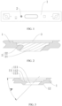
FIG. 1 is a bottom view of a battery liquid injection structure according to embodiments of the present application; -
FIG. 2 is a cross-sectional view of a partial structure of a battery liquid injection structure according to embodiments of the present application; -
FIG. 3 is a cross-sectional view of a partial structural of a top cover piece according to embodiments of the present application; and -
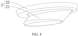
FIG. 4 is a schematic structural diagram of a sealing nail according to embodiments of the present application. - In the figure:
- 1. top cover piece; 11. liquid injection portion; 111. liquid injection hole; 112, first sinking platform; 113. second sinking platform;
- 12. boss;
- 2. sealing member; 21. sealing portion; 22. connecting portion; and
- 3. fixing piece.
- In the related art, because the wall thickness of the top cover is relatively thin, the length of the liquid injection hole is relatively short, and the contact area between the sealing nail and the inner wall of the liquid injection hole is relatively small, that is, the effective sealing area is relatively small. So, the sealing effect is relatively poor, and there is a risk of liquid leakage. Secondly, because the sealing nail is longer, the sealing nail is easy to insertedly insert into the core below the liquid injection hole, thereby resulting in poor product. Further, the liquid injection hole is vertically provided, and the liquid injection hole is not favorable for buffering the liquid because the pressure applied by the liquid injection device is higher.
- As shown in
FIGS. 1 to 2 , the present embodiments provide a battery pack including a battery. The battery includes a body and a battery liquid injection structure. The battery liquid injection structure is located at a top end of the body. The battery liquid injection structure includes atop cover piece 1 and asealing member 2. - Specifically, the
top cover piece 1 is provided with aliquid injection portion 11. The core of the battery is located below theliquid injection portion 11. Theliquid injection portion 11 is provided with aliquid injection hole 111. Theliquid injection hole 111 is obliquely arranged. The sealingmember 2 is sealingly inserted into theliquid injection hole 111. Since theliquid injection hole 111 of theliquid injection section 11 is obliquely arranged, the length of theliquid injection hole 111 is increased. When the sealingmember 2 is sealingly inserted into theliquid injection hole 111, the contact area between the sealingmember 2 and theliquid injection hole 111 is increased. This battery liquid injection structure increases the effective sealing area between theliquid injection portion 11 and the sealingmember 2 with respect to theliquid injection portion 11 vertically provided in the related art, thereby improving the sealing performance and solving the risk of liquid leakage at the sealing position. Further, while the length of the sealingmember 2 is ensured, after the sealingmember 2 is inserted, the sealingmember 2 is further away from the core, thereby preventing the sealingmember 2 from invertedly inserting into the core, and thus increasing the yield of the product. Finally, theliquid injection hole 111 is provided obliquely so as to provide a buffer for the liquid at the time of liquid injection, thereby improving the processing quality of the battery. - Preferably, an axis of the
liquid injection hole 111 is disposed obliquely with respect to an upper surface of thetop cover piece 1. Since the axis of theliquid injection hole 111 of theliquid injection portion 11 is disposed obliquely with respect to the upper surface of thetop cover piece 1, the length of theliquid injection hole 111 is increased. When the sealingmember 2 is sealingly inserted into theliquid injection hole 111, the contact area between the sealingmember 2 and theliquid injection hole 111 is increased, and the sealing performance at theliquid injection hole 111 is improved. - Preferably, the sealing
member 2 includes a sealing nail provided with a sealingportion 21. The sealingportion 21 is sealingly inserted into theliquid injection hole 111. When the sealingportion 21 of the sealing nail is sealingly inserted into theliquid injection hole 111, the contact area between the sealingportion 21 and theliquid injection hole 111 is increased. This battery liquid injection structure increases the effective sealing area between theliquid injection portion 11 and the sealing nail with respect to theliquid injection portion 11 vertically provided in the related art, thereby improving the sealing performance and solving the risk of liquid leakage at the sealing position. Further, when the length of the sealing nail is ensured, the sealingportion 21 is further away from the core after the sealing nail is inserted, thereby preventing the sealing nail from invertedly inserting into the core, and improving the yield of the product. Finally, theliquid injection hole 111 is provided obliquely so as to provide a buffer for the liquid at the time of liquid injection, thereby improving the processing quality of the battery. - Preferably, as shown in
FIG. 3 , an inclination angle of the axis of theliquid injection portion 11 with respect to the upper surface of thetop cover piece 1 is denoted by A, and satisfies 75°≥A≥15°. Specifically, a value of the inclination angle Ais 15°, 25°, 35°, 45°, 55°, 65° and 75°. In this embodiment, the value of the inclination angle of the axis of theliquid injection portion 11 is 45°, with respect to the upper surface of thetop cover piece 1. Further preferably, a shape of a cross-section of theliquid injection hole 111 is circular, elliptical or polygonal, and a shape of the sealingportion 21 matches the shape of theliquid injection hole 111. In this embodiment, the shape of the cross section of theliquid injection hole 111 is elliptical. - Preferably, as shown in
FIGS. 2 to 4 , afirst sinking platform 112 is provided at an end of theliquid injection hole 111, and an inner diameter of thefirst sinking platform 112 is larger than an inner diameter of theliquid injection hole 111. Thefirst sinking platform 112 surrounds theliquid injection hole 111. The sealing nail is provided with a connectingportion 22 embedded in thefirst sinking platform 112, so that the sealing nail is positioned and mounted on theliquid injection portion 11. Further, thefirst sinking platform 112 is capable of limiting the connectingportion 22, and thefirst sinking platform 112 is capable of restricting the connectingportion 22 of the sealing nail from moving toward the inside of thetop cover piece 1, thereby preventing the sealing nail from falling into a housing of the body of the battery. Further, at the time of liquid injection, a liquid injection port of the liquid injection device abuts against thefirst sinking platform 112, so that the liquid is conveyed into theliquid injection hole 111, thereby providing the pre-positioning of the liquid injection device. - The battery liquid injection structure further includes a fixing piece 3 mounted in the
liquid injection portion 11. The fixing piece 3 is press-fitted to the sealing nail. In this way, the sealing nail is connected to theliquid injection portion 11, thereby preventing the sealing nail from falling off. - Preferably, the
liquid injection section 11 is further provided with asecond sinking platform 113 located on a side of thefirst sinking platform 112 away from theliquid injection hole 111. An inner diameter of thesecond sinking platform 113 is larger than the inner diameter of thefirst sinking platform 112. The fixing piece 3 is embedded in thesecond sinking platform 113. In this embodiment, the fixing piece 3 is an aluminum piece, and the fixing piece 3 is welded to the inner wall of thesecond sinking platform 113. The fixing piece 3 has an area larger than an area of the connectingportion 22 of the sealing nail. When the fixing piece 3 is welded to thesecond sinking platform 113, the inner diameter of thesecond sinking platform 113 is larger than the inner diameter of thefirst sinking platform 112, so that the sealing nail is kept at a certain interval from the side wall of thesecond sinking platform 113, thereby preventing the influence on the sealing nail during the welding. In addition, at the time of liquid injection, the liquid injection port of the liquid injection device abuts against thefirst sinking platform 112 to prevent the liquid from falling onto thesecond sinking platform 113, thereby ensuring that the welding quality of the fixing piece 3 and thesecond sinking platform 113 meets the requirements. Thetop cover piece 1 of this embodiment is also made of aluminum, so that thetop cover piece 1 and the fixing piece 3 are welded with each other. - In this embodiment, a height of the
first sinking platform 112 is 0.5 millimeter (mm), and a height of thesecond sinking platform 113 is 0.5 mm. - Preferably, an inner side of the
top cover piece 1 is provided with aboss 12 through which theliquid injection hole 111 penetrates. Theboss 12 increases the structural strength of theliquid injection hole 111 and the length of theliquid injection hole 111, thereby improving the sealing performance.
Claims (21)
- A battery liquid injection structure comprising:a top cover piece (1) provided with a liquid injection portion (11), wherein the liquid injection portion (11) is provided with a liquid injection hole (111) arranged obliquely; anda sealing member (2) sealingly inserted in the liquid injection hole (111).
- The battery liquid injection structure according to claim 1, wherein an axis of the liquid injection hole (111) is inclined with respect to an upper surface of the top cover piece (1).
- The battery liquid injection structure according to claim 1, wherein the sealing member (2) comprises a sealing nail having a sealing portion (21), and the sealing portion (21) is sealingly inserted into the liquid injection hole (111).
- The battery liquid injection structure according to claim 1, wherein an inclination angle of an axis of the liquid injection portion (11) with respect to an upper surface of the top cover piece (1) is denoted by A, and satisfies 75°≥A≥15°.
- The battery liquid injection structure according to claim 1, wherein an end of the liquid injection hole (111) is provided with a first sinking platform (112), the first sinking platform (112) surrounds the liquid injection hole (111), and the sealing nail comprises a connecting portion (22) embedded in the first sinking platform (112).
- The battery liquid injection structure according to claim 5, further comprising a fixing piece (3) mounted in the liquid injection portion (11), and the fixing piece (3) is press-fitted to the sealing nail.
- The battery liquid injection structure according to claim 6, wherein the liquid injection portion (11) is further provided with a second sinking platform (113), the second sinking platform (113) is located on a side of the first sinking platform (112) away from the liquid injection hole (111), an inner diameter of the second sinking platform (113) is greater than an inner diameter of the first sinking platform (112), and the fixing piece (3) is embedded in the second sinking platform (113).
- The battery liquid injection structure according to claim 7, wherein the fixing piece (3) is an aluminum piece, and the fixing piece (3) is welded to an inner wall of the second sinking platform (113).
- The battery liquid injection structure according to any one of claims 1 to 8, wherein a shape of a cross section of the liquid injection hole (111) is circular, elliptical or polygonal, and a shape of the sealing portion (21) matches the shape of the liquid injection hole (111).
- The battery liquid injection structure according to any one of claims 1 to 8, wherein an inner side of the top cover piece (1) is provided with a boss (12), and the liquid injection hole (111) extends through the boss (12).
- A battery comprising a body and a battery liquid injection structure located at a top end of the body, wherein the battery liquid injection structure comprises:a top cover piece (1) provided with a liquid injection portion (11), wherein the liquid injection portion (11) is provided with a liquid injection hole (111) arranged obliquely; anda sealing member (2) sealingly inserted in the liquid injection hole (111).
- The battery liquid injection structure according to claim 11, wherein an axis of the liquid injection hole (111) is inclined with respect to an upper surface of the top cover piece (1).
- The battery liquid injection structure according to claim 11, wherein the sealing member (2) comprises a sealing nail having a sealing portion (21), and the sealing portion (21) is sealingly inserted into the liquid injection hole (111).
- The battery liquid injection structure according to claim 11, wherein an inclination angle of an axis of the liquid injection portion (11) with respect to an upper surface of the top cover piece (1) is denoted by A, and satisfies 75°≥A≥15°.
- The battery liquid injection structure according to claim 11, wherein an end of the liquid injection hole (111) is provided with a first sinking platform (112), the first sinking platform (112) surrounds the liquid injection hole (111), and the sealing nail comprises a connecting portion (22) embedded in the first sinking platform (112).
- The battery liquid injection structure according to claim 15, further comprising a fixing piece (3) mounted in the liquid injection portion (11), and the fixing piece (3) is press-fitted to the sealing nail.
- The battery liquid injection structure according to claim 16, wherein the liquid injection portion (11) is further provided with a second sinking platform (113), the second sinking platform (113) is located on a side of the first sinking platform (112) away from the liquid injection hole (111), an inner diameter of the second sinking platform (113) is greater than an inner diameter of the first sinking platform (112), and the fixing piece (3) is embedded in the second sinking platform (113).
- The battery liquid injection structure according to claim 17, wherein the fixing piece (3) is an aluminum piece, and the fixing piece (3) is welded to an inner wall of the second sinking platform (113).
- The battery liquid injection structure according to any one of claims 11 to 18, wherein a shape of a cross section of the liquid injection hole (111) is circular, elliptical or polygonal, and a shape of the sealing portion (21) matches the shape of the liquid injection hole (111).
- The battery liquid injection structure according to any one of claims 11 to 18, wherein an inner side of the top cover piece (1) is provided with a boss (12), and the liquid injection hole (111) extends through the boss (12).
- A battery pack comprising the battery according to any one of claims 11 to 20.
Applications Claiming Priority (2)
| Application Number | Priority Date | Filing Date | Title |
|---|---|---|---|
| CN202321468477.3U CN220138668U (en) | 2023-06-09 | 2023-06-09 | Battery liquid injection structure, battery and battery pack |
| PCT/CN2024/098079 WO2024251259A1 (en) | 2023-06-09 | 2024-06-07 | Battery electrolyte injection structure, battery, and battery pack |
Publications (2)
| Publication Number | Publication Date |
|---|---|
| EP4513666A1 true EP4513666A1 (en) | 2025-02-26 |
| EP4513666A4 EP4513666A4 (en) | 2025-08-06 |
Family
ID=88951398
Family Applications (1)
| Application Number | Title | Priority Date | Filing Date |
|---|---|---|---|
| EP24804401.8A Pending EP4513666A4 (en) | 2023-06-09 | 2024-06-07 | BATTERY ELECTROLYTE INJECTION STRUCTURE, BATTERY AND BATTERY PACK |
Country Status (4)
| Country | Link |
|---|---|
| US (1) | US20250096446A1 (en) |
| EP (1) | EP4513666A4 (en) |
| CN (1) | CN220138668U (en) |
| WO (1) | WO2024251259A1 (en) |
Families Citing this family (1)
| Publication number | Priority date | Publication date | Assignee | Title |
|---|---|---|---|---|
| CN220138668U (en) * | 2023-06-09 | 2023-12-05 | 湖北亿纬动力有限公司 | Battery liquid injection structure, battery and battery pack |
Family Cites Families (6)
| Publication number | Priority date | Publication date | Assignee | Title |
|---|---|---|---|---|
| JPH06267530A (en) * | 1993-03-16 | 1994-09-22 | Yuasa Corp | Sealed lead acid battery |
| CN202905851U (en) * | 2012-09-17 | 2013-04-24 | 天津力神电池股份有限公司 | Sealing structure of injection hole of battery |
| CN213150888U (en) * | 2020-09-21 | 2021-05-07 | 江苏塔菲尔新能源科技股份有限公司 | Battery top cap and battery |
| CN217589370U (en) * | 2021-12-07 | 2022-10-14 | 湖北亿纬动力有限公司 | Battery injection device |
| CN218385681U (en) * | 2022-10-19 | 2023-01-24 | 江苏中兴派能电池有限公司 | Oblique angle breaking vacuum liquid feeding mechanism |
| CN220138668U (en) * | 2023-06-09 | 2023-12-05 | 湖北亿纬动力有限公司 | Battery liquid injection structure, battery and battery pack |
-
2023
- 2023-06-09 CN CN202321468477.3U patent/CN220138668U/en active Active
-
2024
- 2024-06-07 WO PCT/CN2024/098079 patent/WO2024251259A1/en not_active Ceased
- 2024-06-07 EP EP24804401.8A patent/EP4513666A4/en active Pending
- 2024-11-28 US US18/963,753 patent/US20250096446A1/en active Pending
Also Published As
| Publication number | Publication date |
|---|---|
| CN220138668U (en) | 2023-12-05 |
| US20250096446A1 (en) | 2025-03-20 |
| WO2024251259A1 (en) | 2024-12-12 |
| EP4513666A4 (en) | 2025-08-06 |
Similar Documents
| Publication | Publication Date | Title |
|---|---|---|
| KR101406895B1 (en) | Sealed battery | |
| EP4513666A1 (en) | Battery electrolyte injection structure, battery, and battery pack | |
| EP2341268B1 (en) | Gasket | |
| EP4210157A1 (en) | Cylindrical secondary battery | |
| CN101626088A (en) | Sealed cell | |
| CN220627990U (en) | Battery cell | |
| CN118099682B (en) | Sealing nail, battery cover plate and battery | |
| CN1960027B (en) | Sealed prismatic Li-ion battery | |
| KR100922442B1 (en) | Square battery excellent in sealing property of electrolyte inlet | |
| CN220368121U (en) | Cover plate assembly and single battery | |
| US20250167412A1 (en) | Electrolyte injection o-ring and cylindrical battery manufacturing method using the same | |
| JP4958162B2 (en) | Alkaline battery | |
| JP2005235411A (en) | Oval battery | |
| JP2009176600A (en) | Battery stopper for storage battery | |
| CN107403886A (en) | Battery top cover | |
| JP2015069716A (en) | Safety valve of sealed battery | |
| CN215644862U (en) | Explosion-proof piece and battery | |
| CN221126215U (en) | Sealing member for liquid injection hole, battery top cover and battery | |
| JP2000268810A (en) | Sealed battery | |
| CN120854790A (en) | Cover plate assembly and battery | |
| US20250112308A1 (en) | Cover assembly, battery and battery pack | |
| CN221126216U (en) | Sealing device, battery top cap and battery | |
| CN214877325U (en) | Discharging assembly of tank container | |
| US20250233239A1 (en) | Electrochemical device and electronic device | |
| CN112490547A (en) | Battery top cover, battery top cover forming method, power battery and electric automobile |
Legal Events
| Date | Code | Title | Description |
|---|---|---|---|
| STAA | Information on the status of an ep patent application or granted ep patent |
Free format text: STATUS: UNKNOWN |
|
| STAA | Information on the status of an ep patent application or granted ep patent |
Free format text: STATUS: THE INTERNATIONAL PUBLICATION HAS BEEN MADE |
|
| PUAI | Public reference made under article 153(3) epc to a published international application that has entered the european phase |
Free format text: ORIGINAL CODE: 0009012 |
|
| STAA | Information on the status of an ep patent application or granted ep patent |
Free format text: STATUS: REQUEST FOR EXAMINATION WAS MADE |
|
| 17P | Request for examination filed |
Effective date: 20241118 |
|
| AK | Designated contracting states |
Kind code of ref document: A1 Designated state(s): AL AT BE BG CH CY CZ DE DK EE ES FI FR GB GR HR HU IE IS IT LI LT LU LV MC ME MK MT NL NO PL PT RO RS SE SI SK SM TR |
|
| A4 | Supplementary search report drawn up and despatched |
Effective date: 20250707 |
|
| RIC1 | Information provided on ipc code assigned before grant |
Ipc: H01M 50/645 20210101AFI20250701BHEP |