EP4513649A1 - Battery and electronic device - Google Patents
Battery and electronic device Download PDFInfo
- Publication number
- EP4513649A1 EP4513649A1 EP23900104.3A EP23900104A EP4513649A1 EP 4513649 A1 EP4513649 A1 EP 4513649A1 EP 23900104 A EP23900104 A EP 23900104A EP 4513649 A1 EP4513649 A1 EP 4513649A1
- Authority
- EP
- European Patent Office
- Prior art keywords
- battery
- adhesive segment
- insulating sheet
- outer peripheral
- battery body
- Prior art date
- Legal status (The legal status is an assumption and is not a legal conclusion. Google has not performed a legal analysis and makes no representation as to the accuracy of the status listed.)
- Pending
Links
Images



Classifications
-
- H—ELECTRICITY
- H01—ELECTRIC ELEMENTS
- H01M—PROCESSES OR MEANS, e.g. BATTERIES, FOR THE DIRECT CONVERSION OF CHEMICAL ENERGY INTO ELECTRICAL ENERGY
- H01M50/00—Constructional details or processes of manufacture of the non-active parts of electrochemical cells other than fuel cells, e.g. hybrid cells
- H01M50/10—Primary casings; Jackets or wrappings
- H01M50/183—Sealing members
- H01M50/184—Sealing members characterised by their shape or structure
-
- H—ELECTRICITY
- H01—ELECTRIC ELEMENTS
- H01M—PROCESSES OR MEANS, e.g. BATTERIES, FOR THE DIRECT CONVERSION OF CHEMICAL ENERGY INTO ELECTRICAL ENERGY
- H01M10/00—Secondary cells; Manufacture thereof
- H01M10/05—Accumulators with non-aqueous electrolyte
- H01M10/052—Li-accumulators
-
- H—ELECTRICITY
- H01—ELECTRIC ELEMENTS
- H01M—PROCESSES OR MEANS, e.g. BATTERIES, FOR THE DIRECT CONVERSION OF CHEMICAL ENERGY INTO ELECTRICAL ENERGY
- H01M50/00—Constructional details or processes of manufacture of the non-active parts of electrochemical cells other than fuel cells, e.g. hybrid cells
- H01M50/10—Primary casings; Jackets or wrappings
- H01M50/102—Primary casings; Jackets or wrappings characterised by their shape or physical structure
- H01M50/109—Primary casings; Jackets or wrappings characterised by their shape or physical structure of button or coin shape
-
- H—ELECTRICITY
- H01—ELECTRIC ELEMENTS
- H01M—PROCESSES OR MEANS, e.g. BATTERIES, FOR THE DIRECT CONVERSION OF CHEMICAL ENERGY INTO ELECTRICAL ENERGY
- H01M50/00—Constructional details or processes of manufacture of the non-active parts of electrochemical cells other than fuel cells, e.g. hybrid cells
- H01M50/10—Primary casings; Jackets or wrappings
- H01M50/147—Lids or covers
- H01M50/148—Lids or covers characterised by their shape
- H01M50/153—Lids or covers characterised by their shape for button or coin cells
-
- H—ELECTRICITY
- H01—ELECTRIC ELEMENTS
- H01M—PROCESSES OR MEANS, e.g. BATTERIES, FOR THE DIRECT CONVERSION OF CHEMICAL ENERGY INTO ELECTRICAL ENERGY
- H01M50/00—Constructional details or processes of manufacture of the non-active parts of electrochemical cells other than fuel cells, e.g. hybrid cells
- H01M50/10—Primary casings; Jackets or wrappings
- H01M50/147—Lids or covers
- H01M50/166—Lids or covers characterised by the methods of assembling casings with lids
- H01M50/171—Lids or covers characterised by the methods of assembling casings with lids using adhesives or sealing agents
-
- H—ELECTRICITY
- H01—ELECTRIC ELEMENTS
- H01M—PROCESSES OR MEANS, e.g. BATTERIES, FOR THE DIRECT CONVERSION OF CHEMICAL ENERGY INTO ELECTRICAL ENERGY
- H01M50/00—Constructional details or processes of manufacture of the non-active parts of electrochemical cells other than fuel cells, e.g. hybrid cells
- H01M50/60—Arrangements or processes for filling or topping-up with liquids; Arrangements or processes for draining liquids from casings
- H01M50/609—Arrangements or processes for filling with liquid, e.g. electrolytes
- H01M50/627—Filling ports
-
- Y—GENERAL TAGGING OF NEW TECHNOLOGICAL DEVELOPMENTS; GENERAL TAGGING OF CROSS-SECTIONAL TECHNOLOGIES SPANNING OVER SEVERAL SECTIONS OF THE IPC; TECHNICAL SUBJECTS COVERED BY FORMER USPC CROSS-REFERENCE ART COLLECTIONS [XRACs] AND DIGESTS
- Y02—TECHNOLOGIES OR APPLICATIONS FOR MITIGATION OR ADAPTATION AGAINST CLIMATE CHANGE
- Y02E—REDUCTION OF GREENHOUSE GAS [GHG] EMISSIONS, RELATED TO ENERGY GENERATION, TRANSMISSION OR DISTRIBUTION
- Y02E60/00—Enabling technologies; Technologies with a potential or indirect contribution to GHG emissions mitigation
- Y02E60/10—Energy storage using batteries
Definitions
- Embodiments of the present application relate to the technical field of structure of batteries, and in particular to a battery and an electronic device.
- a button battery is a small-sized battery, an outer peripheral surface of which is covered with a layer of circumferential glue, to give good protection for the button battery.
- the button battery is accommodated in a battery compartment.
- the button battery is fixed in the battery compartment by means of gluing.
- the entire outer peripheral surface of the button battery is covered with the circumferential glue, all the glue after gluing will stick to the circumferential glue, resulting in the body of the button battery not being fixed by glue, and the button battery being prone to shaking when in use and thus having low safety.
- Embodiments of the present application provide a battery and an electronic device to solve the problems of poor fixing effect and low safety of the button battery.
- an embodiment of the present application provides a battery, including a battery body and a protective glue layer.
- the protective glue layer includes a first adhesive segment and a second adhesive segment that are circumferentially coated on an outer peripheral wall of the battery body, and the first adhesive segment and the second adhesive segment have a connecting notch formed therebetween in a circumferential direction of the outer peripheral wall. Both a length of the first adhesive segment and a length of the second adhesive segment are less than a thickness of the battery body in a first direction, to form an exposed area, and part of the outer peripheral wall of the battery body is exposed outside the protective glue layer through the connecting notch and the exposed area.
- the protective glue layer further includes a third adhesive segment, the third adhesive segment is disposed between the first adhesive segment and the second adhesive segment, and the third adhesive segment is connected to both the first adhesive segment and the second adhesive segment.
- a width of the third adhesive segment is smaller than a width of the battery body, and the width of the third adhesive segment is greater than a width of the first adhesive segment and a width of the second adhesive segment.
- the battery body includes a shell, a battery cell, a first shell cover, a second shell cover and a first insulating sheet.
- the shell includes an installation cavity with an opening, and the battery cell is disposed in the installation cavity through the opening.
- the first shell cover, the first insulating sheet and the second shell cover are stacked along the first direction, the first insulating sheet is disposed between the first shell cover and the second shell cover, and the second shell cover is disposed in the installation cavity through the opening.
- the first shell cover has a first through hole
- the first insulating sheet has a second through hole
- a central axis of the first through hole coincides with a central axis of the second through hole
- the second shell cover has a connecting terminal extending toward the first shell cover
- the connecting terminal matches both the first through hole and the second through hole
- the connecting terminal is exposed on a surface of the first shell cover through the first through hole and the second through hole.
- the battery cell includes a first tab and a second tab, the first tab is electrically connected to an inner wall surface of the shell, and the second tab is electrically connected to the second shell cover.
- the first shell cover includes a front connecting surface and a reverse connecting surface opposite to each other along the first direction, the reverse connecting surface is connected to the first insulating sheet, and an edge of the reverse connecting surface is provided with an annular connecting groove, and the annular connecting groove matches the opening.
- the battery body further includes a first adapting member, a second adapting member and a second insulating sheet.
- the front connecting surface is provided with an adhesive sinking platform matching the second insulating sheet.
- a first connecting section of the first adapting member is electrically connected to the front connecting surface of the first shell cover, and a first adaptor of the first adapting member is correspondingly placed on the second insulating sheet.
- a second connecting section of the second adapting member is electrically connected to the connecting terminal, and a second adaptor of the second adapting member is correspondingly placed on the second insulating sheet.
- the first adapting member further includes a positioning member
- the first connecting section includes a first end and a second end
- the first adaptor is connected to the first end
- the positioning member is connected to the second end
- the positioning member extends out of the battery body in a second direction
- the positioning member is disposed on a center line between the first adaptor and the second adaptor.
- the second direction is perpendicular to the first direction.
- the positioning member is parallel to the first connecting section.
- the positioning member is perpendicular to the first connecting section, the positioning member extends along the first direction, and a gap is present between the positioning member and the outer peripheral wall of the battery body.
- the positioning member includes a bent end, and the bent end is perpendicular to the outer peripheral wall of the battery body and extends away from the outer peripheral wall of the battery body.
- a center line of the third adhesive segment is aligned with a center line of the first adapting member and a center line of the second adapting member.
- the connecting notch is symmetrically provided with the first adapting member and the second adapting member along a center line of the battery body.
- an embodiment of the present application also provides an electronic device, which includes the battery described above and a battery compartment.
- the battery is disposed inside the battery compartment, part of the outer peripheral wall of the battery body is exposed outside the protective glue layer through the exposed area, and an adhesive glue layer is disposed between the part of the outer peripheral wall and an inner wall of the battery compartment.
- Another part of the outer peripheral wall of the battery body is exposed outside the protective glue layer through the connecting notch, and the electronic device further includes wirings located in the connecting notch.
- the protective glue layer which does not completely cover the battery body is disposed on the outer peripheral wall of the battery body, so that the part of the outer peripheral wall of the battery body is exposed to the outside, thereby ensuring the installation and fixation of the battery after installed in the battery compartment, avoiding the problem of battery shaking caused by the glue only fixing the protective glue layer but not fixing the battery body, and meanwhile effectively solving the problem of interference between another connecting wire of the device or a connecting wire of the battery and the protective glue layer.
- a button battery is a small-sized battery.
- An outer peripheral surface of the button battery is covered with a layer of circumferential glue, to give good protection for the button battery.
- a battery compartment is a cavity for accommodating the button battery.
- gluing is required to achieve the installation and fixation of the button battery after the button battery is installed in the battery compartment.
- the entire outer peripheral surface of the button battery is covered with the circumferential glue, all the glue after gluing will stick to the circumferential glue, resulting in the body of the button battery not being fixed by the glue and the button battery being prone to shaking when in use, therefore the normal use of the button battery is affected and the safety of the button battery is low.
- the entire outer peripheral surface of the button battery is covered with the circumferential glue, other connecting wires of a device or connecting wires of the button battery are prone to interfering with the circumferential glue, affecting the installation of the button battery into the compartment.
- an embodiment of the present application provides a battery, where an outer peripheral wall of the battery body is provided with a protective glue layer.
- the protective glue layer does not completely cover the battery body, so that part of the outer peripheral wall of the battery body is exposed outside. After gluing, the glue can stick to the part of the outer peripheral wall of the battery body, ensuring the installation and fixation of the battery after installed into the battery compartment, and avoiding the problem of battery shaking caused by the glue only fixing the protective glue layer but not fixing the battery body.
- the embodiments of the present application are applicable to button batteries, and are also applicable to other types of batteries.
- the battery provided in the embodiments of the present application will be described in detail below using the button battery as an example.
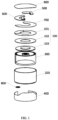
- FIG. 1 is a schematic diagram showing an exploded structure of the battery according to an embodiment of the present application.
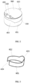
- FIG. 2 is a structural schematic diagram showing an assembled battery according to an embodiment of the present application.
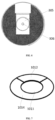
- FIG. 3 is a structural schematic diagram showing a protective glue layer of the battery according to an embodiment of the present application.
- the battery of the embodiment of the present application includes a battery body which includes a shell cover 100, a shell 200 and a battery cell 300.
- the shell 200 includes an installation cavity with an opening, the battery cell 300 is disposed in the installation cavity through the opening, the shell cover 100 matches the opening, and the shell cover 100 is used to seal the installation cavity so that the battery cell 300 is encapsulated in the shell 200.
- the battery further includes a protective glue layer 400 which is coated on the outer peripheral wall of the battery body.
- the protective glue layer 400 includes a first adhesive segment 401 and a second adhesive segment 402 that are circumferentially coated on the outer peripheral wall of the battery body.
- One end of the first adhesive segment 401 is connected to one end of the second adhesive segment 402, and the other end of the first adhesive segment 401 and the other end of the second adhesive segment 402 are spaced apart in a circumferential direction of the outer peripheral wall, to form a connecting notch 404, and the part of the outer peripheral wall of the battery body is exposed outside the protective glue layer 400 through the connecting notch 404.
- both a width of the first adhesive segment 401 and a width of the second adhesive segment 402 are smaller than a width of the battery body (that is, a height in the vertical direction shown in FIG. 2 ) to form an exposed area, and part of the outer peripheral wall of the battery body is exposed outside the protective glue layer 400 through the exposed area.
- the outside of the battery body is coated with the protective glue layer 400;
- the protective glue layer 400 includes the first adhesive segment 401 and the second adhesive segment 402 that are circumferentially coated on the outer peripheral wall of the battery body, and the first adhesive segment 401 and the second adhesive segment 402 have the connecting notch 404 formed therebetween in the circumferential direction of the outer peripheral wall; in the first direction (the vertical direction shown in FIG. 1 and FIG.
- both the length of the first adhesive segment 401 and the length of the second adhesive segment 402 are less than the thickness of the battery body, to form the exposed area; the part of the outer peripheral wall of the battery body is exposed outside the protective glue layer 400 through the connecting notch 404 and the exposed area; after gluing, the glue can be adhered to the part of the outer peripheral wall of the battery body through the exposed area, ensuring the installation and fixation of the battery after installed in the battery compartment, avoiding the problem of the battery shaking caused by the glue only fixing the protective glue layer but not fixing the battery body; meanwhile, the other connecting wires of the device or the connecting wires of the button battery will be routed and connected through the connecting notch 404, effectively solving the problem of the interference between the other connecting wires of the device or the connecting wires of the battery and the protective glue layer 400.
- the one end of the first adhesive segment 401 and the one end of the second adhesive segment 402 can be directly connected; or, the protective glue layer 400 can further include a third adhesive segment 403 that is also circumferentially coated on the outer peripheral wall of the battery body, and the third adhesive segment 403 is disposed between the first adhesive segment 401 and the second adhesive segment 402, and two ends of the third adhesive segment 403 are respectively connected to the first adhesive segment 401 and the second adhesive segment 402.
- a width of the third adhesive segment 403 is smaller than the width of the battery body, also forming the exposed area.
- the width of the third adhesive segment 403 is larger than the width of the first adhesive segment 401 and the width of the second adhesive segment 402; that is, an area by which the outer peripheral wall of the battery body is coated with the third adhesive segment 403 is larger than an area by which the outer peripheral wall of the battery body is coated with the first adhesive segment 401, and is also larger than an area by which the outer peripheral wall of the battery body is coated with the second adhesive segment 402.
- the protective glue layer 400 is ensured to still have a good protective effect, the glue is adhered to the part of the outer peripheral wall of the battery body through the exposed area after gluing.
- first adhesive segment 401 and the second adhesive segment 402 are 2.5-3 mm beneath the outer peripheral wall of the battery body, and the third adhesive segment 403 is 1-2 mm beneath the outer peripheral wall of the battery body, to expose the battery body for easy glue adhesion.
- the other end of the first adhesive segment 401 and the other end of the second adhesive segment 402 are spaced apart by 6-8 mm in the circumferential direction of the outer peripheral wall, to form a 6-8 mm connecting notch 404 for leading the connection wire out of the connecting notch 404, while also increasing the adhesion area between the glue and the battery body.
- FIGs. 4-6 are all structural schematic diagrams showing the battery cell of the battery according to embodiments of the present application.
- the shell cover 100 may include a first shell cover 101 (which may be a negative electrode shell cover), a second shell cover 103 (which may be a positive electrode shell cover) and a first insulating sheet 102.
- the first shell cover 101, the first insulating sheet 102 and the second shell cover 103 are stacked along the first direction (the vertical direction shown in FIG. 1 ), and the first shell cover 101, the first insulating sheet 102 and the second shell cover 103 are adhered together by means of hot pressing.
- the first insulating sheet 102 is disposed between the first shell cover 101 and the second shell cover 103 to avoid mutual interference between the first shell cover 101 and the second shell cover 103.
- the battery cell 300 has a front end surface and a back end surface in the first direction (the vertical direction shown in FIG. 1 and FIG. 2 ).
- the front end surface is adhered with a third insulating sheet 301
- the back end surface is adhered with a fourth insulating sheet 302
- both the third insulating sheet 301 and the fourth insulating sheet 302 have an avoidance hole.
- the battery cell 300 further includes a first tab 305 (which can be a negative tab) and a second tab 303 (which can be a positive tab); the first tab 305 extends outwards through the avoidance hole of the fourth insulating sheet 302 from the back end surface and is bent toward the fourth insulating sheet 302; the second tab 303 extends outwards through the avoidance hole of the third insulating sheet 301 from the front end surface and is bent toward the third insulating sheet 301.
- the third insulating sheet 301 and the fourth insulating sheet 302 are used to prevent the battery cell 300 from interfering with other components.
- the first shell cover 101 includes a front connecting surface 1012 and a reverse connecting surface 1013 opposite to each other along the first direction (the vertical direction shown in FIG. 1 ), and the reverse connecting surface 1013 is connected to the first insulating sheet 102; and an edge of the reverse connecting surface 1013 is provided with an annular connecting groove 1015, the annular connecting groove 1015 matches the opening, and the annular connecting groove 1015 is welded to an end face where the opening is located, so that the first shell cover 101 is electrically connected to the shell 200.
- the first shell cover 101 has a first through hole 1011
- the first insulating sheet 102 has a second through hole
- the central axis of the first through hole 1011 coincides with the central axis of the second through hole.
- the second shell cover 103 has a connecting terminal 1031 (that is, a positive terminal) extending toward the first shell cover 101, the connecting terminal 1031 matches both the first through hole 1011 and the second through hole, the connecting terminal 1031 is connected to both the first through hole 1011 and the second through hole, and finally is exposed on the surface of the first shell cover 101 through the first through hole 1011 and the second through hole.
- the first tab 305 (that is, the negative tab) of the battery cell 300 is welded to an inner wall surface of the shell 200, and the inner wall surface of the shell 200 can be the inner wall surface of the bottom of the shell 200, so that the first tab 305 is also electrically connected to the first shell cover 101.
- the second tab 303 (that is, the positive tab) is welded to the second shell cover 103, so that the second tab 303 is electrically connected to the connecting terminal 1031 (that is, the positive terminal).
- a diameter of a first weld mark 306 on the first tab 305 is smaller than a width of the first tab 305; similarly, a width of a second weld mark 304 on the second tab 303 is smaller than a width of the second tab 303.
- the second adapting member 500 includes a second connecting section 501 and a second adaptor 502 connected to each other.
- the second connecting section 501 is welded to the connecting terminal 1031 (that is, the positive terminal) exposed on the surface of the first shell cover 101 through the first through hole 1011 and the second through hole, so that the second adaptor 502 is electrically connected to the second tab 303 (that is, the positive tab).
- the second adaptor 502 is correspondingly placed on the second insulating sheet 700, and the second insulating sheet 700 is used to prevent the second adaptor 502 from interfering with other components.
- FIG. 12 is a second structural schematic diagram of the battery according to an embodiment of the present application.
- the first adapting member 600 may further include a positioning member 603.
- the first connecting section 601 includes a first end and a second end, the first end is connected to the first adaptor 602, and the second end is connected to the positioning member 603.
- the positioning member 603 extends out of the battery body in a second direction (a horizontal direction shown in FIG. 2 , where the second direction is perpendicular to the first direction), and the positioning member is disposed on a center line between the first adaptor 602 and the second adaptor 502.
- the positioning member 603 can play a positioning role during the installation of the battery into the battery compartment, ensuring that the first adaptor 602 and the second adaptor 502 are spaced apart within a reasonable distance. Meanwhile, it is ensured that the battery does not rotate after the installation of the battery into the battery compartment, to avoid deformation of the positive connecting terminal and the negative connecting terminal.
- the third adhesive segment 403 is disposed between the first adhesive segment 401 and the second adhesive segment 402, and the first adaptor 602 and the second adaptor 502 are close to the third adhesive segment 403; and both the center of the third adhesive segment 403 and the center of the connecting notch 404 are located on the center line between the first adaptor 602 and the second adaptor 502; and the connecting notch 404 is symmetrically disposed with the first adaptor 602 and the second adaptor 502 along a center line of the battery body to ensure that the connecting notch 404 is located directly opposite the first adaptor 602 and the second adaptor 502; and other connecting wires of the device or the connecting wires of the button battery will be routed and connected through the connecting notch 404, to avoid interference with the first adaptor 602 and the second adaptor 502.
- the positioning member 603 is parallel to the first connecting section 601, and the positioning member 603 is parallel to a plane where the second direction is located.
- the positioning member 603 may also be perpendicular to the first connecting section 601, where, after the positioning member 603 extends out of the battery body in the second direction (the horizontal direction shown in FIG. 2 ), it will extend along the first direction, that is, the positioning member 603 will be bent toward the outer peripheral wall of the battery body. Meanwhile, there is a gap between the positioning member 603 and the outer peripheral wall of the battery body to prevent the negatively charged positioning member 603 from affecting the battery body.
- the gap may range from 0.2mm to 0.3 mm.
- the positioning member 603 may be located directly above the protective glue layer 400, or may be located in the exposed area covered with the protective glue layer 400.
- a height of the positioning member 603 in the vertical direction is smaller than the height of the battery body, to avoid interference with other devices after the battery is installed into the battery compartment.
- the positioning member 603 may further include a bent end 604, the bend end 604 is perpendicular to the outer peripheral wall of the battery body and extends away from the outer peripheral wall of the battery body; that is, after bent toward the outer peripheral wall of the battery body, the positioning member 603 will be continually bent along the second direction (the horizontal direction shown in FIG. 10 ) away from the outer peripheral wall of the battery body, to form the bent end 604, which is convenient for technicians to operate.
- the bend end 604 is perpendicular to the outer peripheral wall of the battery body and extends away from the outer peripheral wall of the battery body; that is, after bent toward the outer peripheral wall of the battery body, the positioning member 603 will be continually bent along the second direction (the horizontal direction shown in FIG. 10 ) away from the outer peripheral wall of the battery body, to form the bent end 604, which is convenient for technicians to operate.
- the shell 200 has an installation cavity 202, and a bottom surface 201 of the shell 200 is provided with a liquid-injection hole 203, and through which an electrolyte is injected into the installation cavity 202.
- An edge of the liquid-injection hole 203 is provided with a sealing face 204.
- the battery body further includes a sealing nail 800, the sealing nail 800 has an abutment portion 801 and a sealing protrusion 802, and the sealing protrusion 802 matches the liquid-injection hole 203; and the abutment portion 801 abuts against the sealing face 204 to achieve sealing of the installation cavity 202, while the sealing protrusion 802 is connected to the liquid-injection hole 203.
- abutment portion 801 and the sealing face 204 are welded together.
- the battery body further includes a top insulating sheet 900 disposed above the first adapting member 600 and the second adapting member 500, and the first adaptor 602 and the second adaptor 502 are exposed on the top of the battery body through an indentation of the top insulating sheet 900.
- the electronic device further includes wirings located in the connecting notch 404; and another part of the outer peripheral wall of the battery body is exposed outside the protective glue layer 400 through the connecting notch 404, and the another part of the outer peripheral wall is used for routing, so that the wirings (the other connecting wires or the connecting wires of the button battery) can be routed and connected through the connecting notch 404, effectively solving the problem of interference between the other connecting wires of the device or the connecting wires of the battery and the protective glue layer 400.
- the outside of the battery body is coated with the protective glue layer 400 of the battery
- the protective glue layer 400 includes the first adhesive segment 401 and the second adhesive segment 402 that are circumferentially coated on the outer peripheral wall of the battery body, and the first adhesive segment 401 and the second adhesive segment 402 have the connecting notch 404 formed therebetween in the circumferential direction of the outer peripheral wall; in the first direction (the vertical direction shown in FIG. 1 and FIG.
- both the length of the first adhesive segment 401 and the length of the second adhesive segment 402 are less than the thickness of the battery body to form the exposed area, and the part of the outer peripheral wall of the battery body is exposed outside the protective glue layer 400 through the connecting notch 404 and the exposed area; after gluing, the glue can be adhered to the part of the outer peripheral wall of the battery body through the exposed area, ensuring the installation and fixation of the battery after installed in the battery compartment, avoiding the problem of battery shaking caused by the glue only fixing the protective glue layer but not fixing the battery body; meanwhile, the other connecting wires of the device or the connecting wires of the button battery will be routed and connected through the connecting notch 404, effectively solving the problem of the interference between the other connecting wires of the device or the connecting wires of the battery and the protective glue layer 400.
Landscapes
- Chemical & Material Sciences (AREA)
- Chemical Kinetics & Catalysis (AREA)
- Electrochemistry (AREA)
- General Chemical & Material Sciences (AREA)
- Engineering & Computer Science (AREA)
- Manufacturing & Machinery (AREA)
- Sealing Battery Cases Or Jackets (AREA)
- Connection Of Batteries Or Terminals (AREA)
Abstract
Description
- This disclosure claims priority to the
Chinese patent disclosure No. 202223306513.4, entitled "Battery and Electronic Device", and filed with the China National Intellectual Property Administration on December 9, 2022 - Embodiments of the present application relate to the technical field of structure of batteries, and in particular to a battery and an electronic device.
- Batteries (such as lithium-ion batteries) have been widely used as power supply devices. A button battery is a small-sized battery, an outer peripheral surface of which is covered with a layer of circumferential glue, to give good protection for the button battery. The button battery is accommodated in a battery compartment.
- In the related art, the button battery is fixed in the battery compartment by means of gluing. However, since the entire outer peripheral surface of the button battery is covered with the circumferential glue, all the glue after gluing will stick to the circumferential glue, resulting in the body of the button battery not being fixed by glue, and the button battery being prone to shaking when in use and thus having low safety.
- Embodiments of the present application provide a battery and an electronic device to solve the problems of poor fixing effect and low safety of the button battery.
- On the one hand, an embodiment of the present application provides a battery, including a battery body and a protective glue layer. The protective glue layer includes a first adhesive segment and a second adhesive segment that are circumferentially coated on an outer peripheral wall of the battery body, and the first adhesive segment and the second adhesive segment have a connecting notch formed therebetween in a circumferential direction of the outer peripheral wall. Both a length of the first adhesive segment and a length of the second adhesive segment are less than a thickness of the battery body in a first direction, to form an exposed area, and part of the outer peripheral wall of the battery body is exposed outside the protective glue layer through the connecting notch and the exposed area.
- In some embodiments that may include the above embodiment, the protective glue layer further includes a third adhesive segment, the third adhesive segment is disposed between the first adhesive segment and the second adhesive segment, and the third adhesive segment is connected to both the first adhesive segment and the second adhesive segment. In the first direction, a width of the third adhesive segment is smaller than a width of the battery body, and the width of the third adhesive segment is greater than a width of the first adhesive segment and a width of the second adhesive segment.
- In some embodiments that may include the above embodiment, the battery body includes a shell, a battery cell, a first shell cover, a second shell cover and a first insulating sheet. The shell includes an installation cavity with an opening, and the battery cell is disposed in the installation cavity through the opening. The first shell cover, the first insulating sheet and the second shell cover are stacked along the first direction, the first insulating sheet is disposed between the first shell cover and the second shell cover, and the second shell cover is disposed in the installation cavity through the opening. The first shell cover has a first through hole, the first insulating sheet has a second through hole, a central axis of the first through hole coincides with a central axis of the second through hole, the second shell cover has a connecting terminal extending toward the first shell cover, the connecting terminal matches both the first through hole and the second through hole, and the connecting terminal is exposed on a surface of the first shell cover through the first through hole and the second through hole. The battery cell includes a first tab and a second tab, the first tab is electrically connected to an inner wall surface of the shell, and the second tab is electrically connected to the second shell cover.
- In some embodiments that may include the above embodiment, the first shell cover includes a front connecting surface and a reverse connecting surface opposite to each other along the first direction, the reverse connecting surface is connected to the first insulating sheet, and an edge of the reverse connecting surface is provided with an annular connecting groove, and the annular connecting groove matches the opening.
- In some embodiments that may include the above embodiment, the battery body further includes a first adapting member, a second adapting member and a second insulating sheet. The front connecting surface is provided with an adhesive sinking platform matching the second insulating sheet. A first connecting section of the first adapting member is electrically connected to the front connecting surface of the first shell cover, and a first adaptor of the first adapting member is correspondingly placed on the second insulating sheet. A second connecting section of the second adapting member is electrically connected to the connecting terminal, and a second adaptor of the second adapting member is correspondingly placed on the second insulating sheet.
- In some embodiments that may include the above embodiment, the first adapting member further includes a positioning member, the first connecting section includes a first end and a second end, the first adaptor is connected to the first end, the positioning member is connected to the second end, the positioning member extends out of the battery body in a second direction, and the positioning member is disposed on a center line between the first adaptor and the second adaptor. The second direction is perpendicular to the first direction.
- In some embodiments which may include the above embodiment, the positioning member is parallel to the first connecting section.
- In some embodiments that may include the above embodiment, the positioning member is perpendicular to the first connecting section, the positioning member extends along the first direction, and a gap is present between the positioning member and the outer peripheral wall of the battery body.
- In some embodiments that may include the above embodiment, the positioning member includes a bent end, and the bent end is perpendicular to the outer peripheral wall of the battery body and extends away from the outer peripheral wall of the battery body.
- In some embodiments that may include the above embodiment, a center line of the third adhesive segment is aligned with a center line of the first adapting member and a center line of the second adapting member.
- In some embodiments that may include the above embodiment, the connecting notch is symmetrically provided with the first adapting member and the second adapting member along a center line of the battery body.
- On the other hand, an embodiment of the present application also provides an electronic device, which includes the battery described above and a battery compartment. The battery is disposed inside the battery compartment, part of the outer peripheral wall of the battery body is exposed outside the protective glue layer through the exposed area, and an adhesive glue layer is disposed between the part of the outer peripheral wall and an inner wall of the battery compartment. Another part of the outer peripheral wall of the battery body is exposed outside the protective glue layer through the connecting notch, and the electronic device further includes wirings located in the connecting notch.
- In the battery and the electronic device provided in the embodiments of the present application, the protective glue layer which does not completely cover the battery body is disposed on the outer peripheral wall of the battery body, so that the part of the outer peripheral wall of the battery body is exposed to the outside, thereby ensuring the installation and fixation of the battery after installed in the battery compartment, avoiding the problem of battery shaking caused by the glue only fixing the protective glue layer but not fixing the battery body, and meanwhile effectively solving the problem of interference between another connecting wire of the device or a connecting wire of the battery and the protective glue layer.
- The accompanying drawings, which are incorporated in this specification and constitute a part of this specification, illustrate the embodiments complying with the present application and serve to explain the principles of the present application together with this specification.
-
FIG. 1 is a schematic diagram showing an exploded structure of a battery according to an embodiment of the present application. -
FIG. 2 is a first structural schematic diagram showing the battery according to an embodiment of the present application. -
FIG. 3 is a structural schematic diagram showing a circumferential glue of the battery according to an embodiment of the present application. -
FIG. 4 is a first structural schematic diagram showing a battery cell of the battery according to an embodiment of the present application. -
FIG. 5 is a second structural schematic diagram showing the battery cell of the battery according to an embodiment of the present application. -
FIG. 6 is a third structural schematic diagram showing the battery cell of the battery according to an embodiment of the present application. -
FIG. 7 is a first structural schematic diagram showing a first shell cover of the battery according to an embodiment of the present application. -
FIG. 8 is a second structural schematic diagram showing the first shell cover of the battery according to an embodiment of the present application. -
FIG. 9 is a structural schematic diagram showing a second shell cover of the battery according to an embodiment of the present application. -
FIG. 10 is a structural schematic diagram showing a first adapting member of the battery according to an embodiment of the present application. -
FIG. 11 is a structural schematic diagram showing a second adapting member of the battery according to an embodiment of the present application. -
FIG. 12 is a second structural schematic diagram showing the battery according to an embodiment of the present application. -
FIG. 13 is a cross-sectional view along A-A direction inFIG. 12 . -
FIG. 14 is an enlarged view of portion B inFIG. 13 . -
FIG. 15 is a structural schematic diagram showing a shell of the battery according to an embodiment of the present application. -
FIG. 16 is a cross-sectional view taken along C-C direction inFIG. 15 . -
FIG. 17 is an enlarged view of part D inFIG. 16 . -
FIG. 18 is a structural schematic diagram showing a sealing nail of the battery according to an embodiment of the present application. -
- 100: Shell cover;
- 101: First shell cover; 102: First insulating sheet; 103: Second shell cover;
- 1011: First through hole; 1012: Front connecting surface; 1013: Reverse connecting surface; 1014: Adhesive sinking platform; 1015: Annular connecting groove; 1031: Connecting terminal;
- 200: Shell;
- 201: Bottom surface; 202: Installation cavity; 203: Liquid-injection hole; 204: Sealing face;
- 300: Battery cell;
- 301: Third insulating sheet; 302: Fourth insulating sheet; 303: Second tab; 304: Second weld mark; 305: First tab; 306: First weld mark;
- 400: Protective glue layer;
- 401: First adhesive segment; 402: Second adhesive segment; 403: Third adhesive segment; 404: Connecting notch;
- 500: Second adapting member;
- 501: Second connecting section; 502: Second adaptor;
- 600: First adapting member;
- 601: First connecting section; 602: First adaptor; 603: Positioning member; 604: Bent end;
- 700: Second insulating sheet;
- 800: Sealing nail;
- 801: Abutment portion; 802: Sealing protrusion;
- 900: Top insulating sheet.
- The specific embodiments of the present application have been illustrated according to above-described accompanying drawings, which will be described in more detail hereinafter. These accompanying drawings and textual description are not intended to limit the scope of the present application in any way, but rather to illustrate the concept of the present application to those skilled in the art with reference to the specific embodiment.
- A button battery is a small-sized battery. An outer peripheral surface of the button battery is covered with a layer of circumferential glue, to give good protection for the button battery. A battery compartment is a cavity for accommodating the button battery. In the related art, gluing is required to achieve the installation and fixation of the button battery after the button battery is installed in the battery compartment. However, since the entire outer peripheral surface of the button battery is covered with the circumferential glue, all the glue after gluing will stick to the circumferential glue, resulting in the body of the button battery not being fixed by the glue and the button battery being prone to shaking when in use, therefore the normal use of the button battery is affected and the safety of the button battery is low. Meanwhile, since the entire outer peripheral surface of the button battery is covered with the circumferential glue, other connecting wires of a device or connecting wires of the button battery are prone to interfering with the circumferential glue, affecting the installation of the button battery into the compartment.
- In light of the above technical problems, an embodiment of the present application provides a battery, where an outer peripheral wall of the battery body is provided with a protective glue layer. The protective glue layer does not completely cover the battery body, so that part of the outer peripheral wall of the battery body is exposed outside. After gluing, the glue can stick to the part of the outer peripheral wall of the battery body, ensuring the installation and fixation of the battery after installed into the battery compartment, and avoiding the problem of battery shaking caused by the glue only fixing the protective glue layer but not fixing the battery body. Meanwhile, other connecting wires of the device or the connecting wires of the button battery will be routed and connected through the part of the outer peripheral wall exposed to the outside, effectively solving the problem of the interference between the other connecting wires of the device or the connecting wires of the battery and the protective glue layer.
- The embodiments of the present application are applicable to button batteries, and are also applicable to other types of batteries. The battery provided in the embodiments of the present application will be described in detail below using the button battery as an example.
- In order to make the purpose, technical solutions and advantages of embodiments of the present application clearer, the technical solutions in the embodiments of the present application will be clearly and comprehensively described below in combination with the accompanying drawings in the embodiments of the present application. Obviously, the described embodiments are only part of the embodiments, not all of the embodiments, of the present application. Based on the embodiments in the present application, all other embodiments obtained by those skilled in this field without any creative effort shall fall within the protection scope of the present application.
- Please referring to
FIGs. 1-3 ,FIG. 1 is a schematic diagram showing an exploded structure of the battery according to an embodiment of the present application.FIG. 2 is a structural schematic diagram showing an assembled battery according to an embodiment of the present application.FIG. 3 is a structural schematic diagram showing a protective glue layer of the battery according to an embodiment of the present application. The battery of the embodiment of the present application includes a battery body which includes ashell cover 100, ashell 200 and abattery cell 300. Theshell 200 includes an installation cavity with an opening, thebattery cell 300 is disposed in the installation cavity through the opening, theshell cover 100 matches the opening, and theshell cover 100 is used to seal the installation cavity so that thebattery cell 300 is encapsulated in theshell 200. - The battery further includes a
protective glue layer 400 which is coated on the outer peripheral wall of the battery body. Theprotective glue layer 400 includes a firstadhesive segment 401 and a secondadhesive segment 402 that are circumferentially coated on the outer peripheral wall of the battery body. One end of the firstadhesive segment 401 is connected to one end of the secondadhesive segment 402, and the other end of the firstadhesive segment 401 and the other end of the secondadhesive segment 402 are spaced apart in a circumferential direction of the outer peripheral wall, to form a connectingnotch 404, and the part of the outer peripheral wall of the battery body is exposed outside theprotective glue layer 400 through the connectingnotch 404. - Meanwhile, in a first direction (a vertical direction shown in
FIG. 1 andFIG. 2 ), both a width of the firstadhesive segment 401 and a width of the secondadhesive segment 402 are smaller than a width of the battery body (that is, a height in the vertical direction shown inFIG. 2 ) to form an exposed area, and part of the outer peripheral wall of the battery body is exposed outside theprotective glue layer 400 through the exposed area. - In the battery of the embodiment of the present application, the outside of the battery body is coated with the protective glue layer 400; the protective glue layer 400 includes the first adhesive segment 401 and the second adhesive segment 402 that are circumferentially coated on the outer peripheral wall of the battery body, and the first adhesive segment 401 and the second adhesive segment 402 have the connecting notch 404 formed therebetween in the circumferential direction of the outer peripheral wall; in the first direction (the vertical direction shown in
FIG. 1 andFIG. 2 ), both the length of the first adhesive segment 401 and the length of the second adhesive segment 402 are less than the thickness of the battery body, to form the exposed area; the part of the outer peripheral wall of the battery body is exposed outside the protective glue layer 400 through the connecting notch 404 and the exposed area; after gluing, the glue can be adhered to the part of the outer peripheral wall of the battery body through the exposed area, ensuring the installation and fixation of the battery after installed in the battery compartment, avoiding the problem of the battery shaking caused by the glue only fixing the protective glue layer but not fixing the battery body; meanwhile, the other connecting wires of the device or the connecting wires of the button battery will be routed and connected through the connecting notch 404, effectively solving the problem of the interference between the other connecting wires of the device or the connecting wires of the battery and the protective glue layer 400. - In the embodiment of the present application, the one end of the first
adhesive segment 401 and the one end of the secondadhesive segment 402 can be directly connected; or, theprotective glue layer 400 can further include a thirdadhesive segment 403 that is also circumferentially coated on the outer peripheral wall of the battery body, and the thirdadhesive segment 403 is disposed between the firstadhesive segment 401 and the secondadhesive segment 402, and two ends of the thirdadhesive segment 403 are respectively connected to the firstadhesive segment 401 and the secondadhesive segment 402. - In the first direction (the vertical direction shown in
FIG. 1 andFIG. 2 ), a width of the thirdadhesive segment 403 is smaller than the width of the battery body, also forming the exposed area. The width of the thirdadhesive segment 403 is larger than the width of the firstadhesive segment 401 and the width of the secondadhesive segment 402; that is, an area by which the outer peripheral wall of the battery body is coated with the thirdadhesive segment 403 is larger than an area by which the outer peripheral wall of the battery body is coated with the firstadhesive segment 401, and is also larger than an area by which the outer peripheral wall of the battery body is coated with the secondadhesive segment 402. While theprotective glue layer 400 is ensured to still have a good protective effect, the glue is adhered to the part of the outer peripheral wall of the battery body through the exposed area after gluing. - Optionally, the first
adhesive segment 401 and the secondadhesive segment 402 are 2.5-3 mm beneath the outer peripheral wall of the battery body, and the thirdadhesive segment 403 is 1-2 mm beneath the outer peripheral wall of the battery body, to expose the battery body for easy glue adhesion. - Optionally, the other end of the first
adhesive segment 401 and the other end of the secondadhesive segment 402 are spaced apart by 6-8 mm in the circumferential direction of the outer peripheral wall, to form a 6-8mm connecting notch 404 for leading the connection wire out of the connectingnotch 404, while also increasing the adhesion area between the glue and the battery body. - Referring to
FIG. 1 andFIGs. 4-6, FIGs. 4-6 are all structural schematic diagrams showing the battery cell of the battery according to embodiments of the present application. In the embodiments of the present application, theshell cover 100 may include a first shell cover 101 (which may be a negative electrode shell cover), a second shell cover 103 (which may be a positive electrode shell cover) and a first insulatingsheet 102. Thefirst shell cover 101, the first insulatingsheet 102 and thesecond shell cover 103 are stacked along the first direction (the vertical direction shown inFIG. 1 ), and thefirst shell cover 101, the first insulatingsheet 102 and thesecond shell cover 103 are adhered together by means of hot pressing. The first insulatingsheet 102 is disposed between thefirst shell cover 101 and thesecond shell cover 103 to avoid mutual interference between thefirst shell cover 101 and thesecond shell cover 103. - The
battery cell 300 has a front end surface and a back end surface in the first direction (the vertical direction shown inFIG. 1 andFIG. 2 ). The front end surface is adhered with a thirdinsulating sheet 301, and the back end surface is adhered with a fourth insulatingsheet 302, and both the third insulatingsheet 301 and the fourth insulatingsheet 302 have an avoidance hole. Thebattery cell 300 further includes a first tab 305 (which can be a negative tab) and a second tab 303 (which can be a positive tab); thefirst tab 305 extends outwards through the avoidance hole of the fourth insulatingsheet 302 from the back end surface and is bent toward the fourth insulatingsheet 302; thesecond tab 303 extends outwards through the avoidance hole of the third insulatingsheet 301 from the front end surface and is bent toward the third insulatingsheet 301. The thirdinsulating sheet 301 and the fourth insulatingsheet 302 are used to prevent thebattery cell 300 from interfering with other components. - Referring to
FIG. 1 andFIGs. 7-9 ,FIG. 7 andFIG. 8 are structural schematic diagrams of the first shell cover of the battery according to embodiments of the present application, andFIG. 9 is a structural schematic diagram of the second shell cover of the battery according to an embodiment of the present application. After thefirst shell cover 101, the first insulatingsheet 102 and thesecond shell cover 103 are adhered together by means of hot pressing, thesecond shell cover 103 is disposed in the installation cavity; since thefirst shell cover 101 matches the opening, thefirst shell cover 101 is electrically connected to theshell 200 when thesecond shell cover 103 is disposed in the installation cavity through the opening. Thefirst shell cover 101 includes a front connectingsurface 1012 and areverse connecting surface 1013 opposite to each other along the first direction (the vertical direction shown inFIG. 1 ), and thereverse connecting surface 1013 is connected to the first insulatingsheet 102; and an edge of thereverse connecting surface 1013 is provided with an annular connectinggroove 1015, the annular connectinggroove 1015 matches the opening, and the annular connectinggroove 1015 is welded to an end face where the opening is located, so that thefirst shell cover 101 is electrically connected to theshell 200. - In the above embodiment of the present application, the
first shell cover 101 has a first throughhole 1011, the first insulatingsheet 102 has a second through hole, and the central axis of the first throughhole 1011 coincides with the central axis of the second through hole. Thesecond shell cover 103 has a connecting terminal 1031 (that is, a positive terminal) extending toward thefirst shell cover 101, the connecting terminal 1031 matches both the first throughhole 1011 and the second through hole, the connecting terminal 1031 is connected to both the first throughhole 1011 and the second through hole, and finally is exposed on the surface of thefirst shell cover 101 through the first throughhole 1011 and the second through hole. - After the
battery cell 300 is placed in the installation cavity of theshell 200, the first tab 305 (that is, the negative tab) of thebattery cell 300 is welded to an inner wall surface of theshell 200, and the inner wall surface of theshell 200 can be the inner wall surface of the bottom of theshell 200, so that thefirst tab 305 is also electrically connected to thefirst shell cover 101. The second tab 303 (that is, the positive tab) is welded to thesecond shell cover 103, so that thesecond tab 303 is electrically connected to the connecting terminal 1031 (that is, the positive terminal). - It should be noted that, with reference to
FIG. 5 andFIG. 6 continually, a diameter of afirst weld mark 306 on thefirst tab 305 is smaller than a width of thefirst tab 305; similarly, a width of asecond weld mark 304 on thesecond tab 303 is smaller than a width of thesecond tab 303. - Referring to
FIG. 1 andFIG. 7 continually, the battery body may further include a second insulatingsheet 700, thefront connecting surface 1012 is provided with anadhesive sinking platform 1014 matching the second insulatingsheet 700, and the second insulatingsheet 700 is connected to theadhesive sinking platform 1014. Referring toFIG. 10 and FIG. 11, FIG. 10 is a structural schematic diagram showing a first adapting member of the battery according to an embodiment of the present application, andFIG. 11 is a structural schematic diagram showing a second adapting member of the battery according to an embodiment of the present application. In the above embodiment of the present application, the battery body may further include afirst adapting member 600 and asecond adapting member 500. Thefirst adapting member 600 includes a first connectingsection 601 and afirst adaptor 602 connected to each other, the first connectingsection 601 is welded to thefront connecting surface 1012 of thefirst shell cover 101, so that thefirst adaptor 602 is electrically connected to the first tab 305 (that is, the negative tab). Meanwhile, thefirst adaptor 602 is correspondingly placed on the second insulatingsheet 700, and the second insulatingsheet 700 is used to prevent thefirst adaptor 602 from interfering with other components. - The
second adapting member 500 includes a second connectingsection 501 and asecond adaptor 502 connected to each other. The second connectingsection 501 is welded to the connecting terminal 1031 (that is, the positive terminal) exposed on the surface of thefirst shell cover 101 through the first throughhole 1011 and the second through hole, so that thesecond adaptor 502 is electrically connected to the second tab 303 (that is, the positive tab). Meanwhile, thesecond adaptor 502 is correspondingly placed on the second insulatingsheet 700, and the second insulatingsheet 700 is used to prevent thesecond adaptor 502 from interfering with other components. - Referring to
FIG. 2 ,FIG. 10 andFIG. 12 continually,FIG. 12 is a second structural schematic diagram of the battery according to an embodiment of the present application. In the above embodiment of the present application, the first adaptingmember 600 may further include apositioning member 603. The first connectingsection 601 includes a first end and a second end, the first end is connected to thefirst adaptor 602, and the second end is connected to thepositioning member 603. The positioningmember 603 extends out of the battery body in a second direction (a horizontal direction shown inFIG. 2 , where the second direction is perpendicular to the first direction), and the positioning member is disposed on a center line between thefirst adaptor 602 and thesecond adaptor 502. The positioningmember 603 can play a positioning role during the installation of the battery into the battery compartment, ensuring that thefirst adaptor 602 and thesecond adaptor 502 are spaced apart within a reasonable distance. Meanwhile, it is ensured that the battery does not rotate after the installation of the battery into the battery compartment, to avoid deformation of the positive connecting terminal and the negative connecting terminal. - In the above embodiment of the present application, the third
adhesive segment 403 is disposed between the firstadhesive segment 401 and the secondadhesive segment 402, and thefirst adaptor 602 and thesecond adaptor 502 are close to the thirdadhesive segment 403; and both the center of the thirdadhesive segment 403 and the center of the connectingnotch 404 are located on the center line between thefirst adaptor 602 and thesecond adaptor 502; and the connectingnotch 404 is symmetrically disposed with thefirst adaptor 602 and thesecond adaptor 502 along a center line of the battery body to ensure that the connectingnotch 404 is located directly opposite thefirst adaptor 602 and thesecond adaptor 502; and other connecting wires of the device or the connecting wires of the button battery will be routed and connected through the connectingnotch 404, to avoid interference with thefirst adaptor 602 and thesecond adaptor 502. - Referring to
FIG. 2 continually, in the above embodiment of the present application, the positioningmember 603 is parallel to the first connectingsection 601, and thepositioning member 603 is parallel to a plane where the second direction is located. - In the above embodiment of the present application, the positioning
member 603 may also be perpendicular to the first connectingsection 601, where, after thepositioning member 603 extends out of the battery body in the second direction (the horizontal direction shown inFIG. 2 ), it will extend along the first direction, that is, the positioningmember 603 will be bent toward the outer peripheral wall of the battery body. Meanwhile, there is a gap between the positioningmember 603 and the outer peripheral wall of the battery body to prevent the negatively chargedpositioning member 603 from affecting the battery body. - Optionally, the gap may range from 0.2mm to 0.3 mm.
- It should be noted that after the
positioning member 603 is bent toward the outer peripheral wall of the battery body, the positioningmember 603 may be located directly above theprotective glue layer 400, or may be located in the exposed area covered with theprotective glue layer 400. - It should further be noted that after the
positioning member 603 is bent toward the outer peripheral wall of the battery body, a height of thepositioning member 603 in the vertical direction is smaller than the height of the battery body, to avoid interference with other devices after the battery is installed into the battery compartment. - In the above embodiment of the present application, the positioning
member 603 may further include abent end 604, thebend end 604 is perpendicular to the outer peripheral wall of the battery body and extends away from the outer peripheral wall of the battery body; that is, after bent toward the outer peripheral wall of the battery body, the positioningmember 603 will be continually bent along the second direction (the horizontal direction shown inFIG. 10 ) away from the outer peripheral wall of the battery body, to form thebent end 604, which is convenient for technicians to operate. - Referring to
FIGs. 13-18 , theshell 200 has aninstallation cavity 202, and abottom surface 201 of theshell 200 is provided with a liquid-injection hole 203, and through which an electrolyte is injected into theinstallation cavity 202. An edge of the liquid-injection hole 203 is provided with a sealingface 204. The battery body further includes a sealingnail 800, the sealingnail 800 has anabutment portion 801 and a sealingprotrusion 802, and the sealingprotrusion 802 matches the liquid-injection hole 203; and theabutment portion 801 abuts against the sealingface 204 to achieve sealing of theinstallation cavity 202, while the sealingprotrusion 802 is connected to the liquid-injection hole 203. - It should be noted that the
abutment portion 801 and the sealingface 204 are welded together. - Referring to
FIG. 1 andFIG. 2 continually, in the embodiment of the present application, the battery body further includes a top insulatingsheet 900 disposed above the first adaptingmember 600 and thesecond adapting member 500, and thefirst adaptor 602 and thesecond adaptor 502 are exposed on the top of the battery body through an indentation of the top insulatingsheet 900. - The electronic device further provided in this embodiment includes the battery described above and the battery compartment, where the battery is disposed in the battery compartment; and the part of the outer peripheral wall of the battery body is exposed outside the
protective glue layer 400 through the exposed area; after gluing, the glue can be adhered to the part of the outer peripheral wall of the battery body through the exposed area, so that the adhesive glue layer is provided between the part of the outer peripheral wall and the inner wall of the battery compartment, thereby ensuring that the battery is installed and fixed after being installed in the battery compartment, and avoiding the problem of battery shaking caused by the glue only fixing theprotective glue layer 400 but not fixing the battery body. - Meanwhile, the electronic device further includes wirings located in the connecting
notch 404; and another part of the outer peripheral wall of the battery body is exposed outside theprotective glue layer 400 through the connectingnotch 404, and the another part of the outer peripheral wall is used for routing, so that the wirings (the other connecting wires or the connecting wires of the button battery) can be routed and connected through the connectingnotch 404, effectively solving the problem of interference between the other connecting wires of the device or the connecting wires of the battery and theprotective glue layer 400. - In the battery and the electronic device provided in the embodiments, the outside of the battery body is coated with the protective glue layer 400 of the battery, and the protective glue layer 400 includes the first adhesive segment 401 and the second adhesive segment 402 that are circumferentially coated on the outer peripheral wall of the battery body, and the first adhesive segment 401 and the second adhesive segment 402 have the connecting notch 404 formed therebetween in the circumferential direction of the outer peripheral wall; in the first direction (the vertical direction shown in
FIG. 1 andFIG. 2 ), both the length of the first adhesive segment 401 and the length of the second adhesive segment 402 are less than the thickness of the battery body to form the exposed area, and the part of the outer peripheral wall of the battery body is exposed outside the protective glue layer 400 through the connecting notch 404 and the exposed area; after gluing, the glue can be adhered to the part of the outer peripheral wall of the battery body through the exposed area, ensuring the installation and fixation of the battery after installed in the battery compartment, avoiding the problem of battery shaking caused by the glue only fixing the protective glue layer but not fixing the battery body; meanwhile, the other connecting wires of the device or the connecting wires of the button battery will be routed and connected through the connecting notch 404, effectively solving the problem of the interference between the other connecting wires of the device or the connecting wires of the battery and the protective glue layer 400. - Finally, it should be noted that the above embodiments are only used to illustrate, rather than to limit, the technical solutions of the present application. Although the present application has been described in detail with reference to the aforementioned embodiments, those ordinarily skilled in the art should understand that: the technical solutions recited in the aforementioned embodiments can still be amended, or some or all of the technical features therein can be replaced equivalently. However, such amendments or replacements do not make the essence of the corresponding technical solutions deviate from the scope of the technical solutions in the embodiments of the present application.
Claims (20)
- A battery, comprising: a battery body and a protective glue layer; wherein the protective glue layer comprises a first adhesive segment and a second adhesive segment that are circumferentially coated on an outer peripheral wall of the battery body, and the first adhesive segment and the second adhesive segment have a connecting notch formed therebetween in a circumferential direction of the outer peripheral wall;
both a length of the first adhesive segment and a length of the second adhesive segment are less than a thickness of the battery body in a first direction, to form an exposed area; and part of the outer peripheral wall of the battery body is exposed outside the protective glue layer through the connecting notch and the exposed area. - The battery according to claim 1, wherein the protective glue layer further comprises a third adhesive segment, the third adhesive segment is disposed between the first adhesive segment and the second adhesive segment, and the third adhesive segment is connected to both the first adhesive segment and the second adhesive segment;
in the first direction, a width of the third adhesive segment is smaller than a width of the battery body, and the width of the third adhesive segment is greater than a width of the first adhesive segment and a width of the second adhesive segment. - The battery according to claim 2, wherein the battery body comprises a shell, a battery cell, a first shell cover, a second shell cover and a first insulating sheet; the shell comprises an installation cavity with an opening, and the battery cell is disposed in the installation cavity through the opening;the first shell cover, the first insulating sheet and the second shell cover are stacked along the first direction, the first insulating sheet is disposed between the first shell cover and the second shell cover, and the second shell cover is disposed in the installation cavity through the opening;the first shell cover has a first through hole, the first insulating sheet has a second through hole, a central axis of the first through hole coincides with a central axis of the second through hole, the second shell cover has a connecting terminal extending toward the first shell cover, the connecting terminal matches both the first through hole and the second through hole, and the connecting terminal is exposed on a surface of the first shell cover through the first through hole and the second through hole;the battery cell comprises a first tab and a second tab, the first tab is electrically connected to an inner wall surface of the shell, and the second tab is electrically connected to the second shell cover.
- The battery according to claim 3, wherein the first shell cover comprises a front connecting surface and a reverse connecting surface opposite to each other along the first direction, the reverse connecting surface is connected to the first insulating sheet, and an edge of the reverse connecting surface is provided with an annular connecting groove, and the annular connecting groove matches the opening.
- The battery according to claim 4, wherein the battery body further comprises a first adapting member, a second adapting member and a second insulating sheet;the front connecting surface is provided with an adhesive sinking platform matching the second insulating sheet;a first connecting section of the first adapting member is electrically connected to the front connecting surface of the first shell cover, and a first adaptor of the first adapting member is correspondingly placed on the second insulating sheet;a second connecting section of the second adapting member is electrically connected to the connecting terminal, and a second adaptor of the second adapting member is correspondingly placed on the second insulating sheet.
- The battery according to claim 5, wherein the first adapting member further comprises a positioning member, the first connecting section comprises a first end and a second end, the first adaptor is connected to the first end, the positioning member is connected to the second end, the positioning member extends out of the battery body in a second direction, and the positioning member is disposed on a center line between the first adaptor and the second adaptor;
wherein the second direction is perpendicular to the first direction. - The battery according to claim 6, wherein the positioning member is parallel to the first connecting section.
- The battery according to claim 6, wherein the positioning member is perpendicular to the first connecting section, the positioning member extends along the first direction, and a gap is present between the positioning member and the outer peripheral wall of the battery body.
- The battery according to claim 8, wherein the positioning member comprises a bent end, and the bent end is perpendicular to the outer peripheral wall of the battery body and extends away from the outer peripheral wall of the battery body.
- The battery according to claim 5, wherein a center line of the third adhesive segment is aligned with a center line of a gap between the first adapting member and the second adapting member.
- The battery according to claim 5, wherein the connecting notch is symmetrically provided with the first adapting member and the second adapting member along a center line of the battery body.
- The battery according to claim 2, wherein in the first direction, the width of the first adhesive segment and the width of the second adhesive segment are smaller than a width of the outer peripheral wall of the battery body by 2.5 to 3 mm, and the width of the third adhesive segment is smaller than the width of the outer peripheral wall of the battery body by 1 to 2 mm.
- The battery according to claim 2, wherein one end of the first adhesive segment and one end of the second adhesive segment are connected to the third adhesive segment, and the other end of the first adhesive segment and the other end of the second adhesive segment are spaced apart to form, in the circumferential direction of the outer peripheral wall of the battery body, the connecting notch of 6 to 8 mm.
- The battery according to claim 3, wherein the first tab is welded to the inner wall surface of the shell, and a projection area of a first weld mark on the first tab in the first direction is smaller than a projection area of the first tab in the first direction;
the second tab is welded to the second shell cover, and a projection area of a second weld mark on the second tab in the first direction is smaller than a projection area of the second tab in the first direction. - The battery according to claim 3, wherein the shell is provided with a liquid-injection hole, and an edge of the liquid-injection hole is provided with a sealing face;
the battery body further comprises a sealing nail, the sealing nail has an abutment portion and a sealing protrusion, and the sealing protrusion matches the liquid-injection hole; and the abutment portion abuts against the sealing face while the sealing protrusion is connected to the liquid-injection hole. - The battery according to claim 15, wherein the abutment portion is welded to the sealing face.
- The battery according to claim 5, wherein the battery cell has a front end surface and a back end surface in the first direction, the front end surface is adhered with a third insulating sheet, and the back end surface is adhered with a fourth insulating sheet;
both the third insulating sheet and the fourth insulating sheet have an avoidance hole, and the first tab extends outwards through the avoidance hole of the fourth insulating sheet from the back end surface and is bent toward the fourth insulating sheet; the second tab extends outwards through the avoidance hole of the third insulating sheet from the front end surface and is bent toward the third insulating sheet. - The battery according to claim 5, wherein the battery body further comprises a top insulating sheet disposed above the first adapting member and the second adapting member, and the first adaptor and the second adaptor are exposed on a top of the battery body through an indentation of the top insulating sheet.
- The battery according to claim 8, wherein the gap between the positioning member and the outer peripheral wall of the battery body ranges from 0.2mm to 0.3 mm.
- An electronic device, comprising the battery according to any one of claims 1 to 19 and a battery compartment; the battery is disposed inside the battery compartment, part of an outer peripheral wall of a battery body is exposed outside a protective glue layer through an exposed area, and an adhesive glue layer is disposed between the part of the outer peripheral wall and an inner wall of the battery compartment;
another part of the outer peripheral wall of the battery body is exposed outside the protective glue layer through a connecting notch, and the electronic device further comprises wirings located in the connecting notch.
Applications Claiming Priority (2)
| Application Number | Priority Date | Filing Date | Title |
|---|---|---|---|
| CN202223306513.4U CN218827670U (en) | 2022-12-09 | 2022-12-09 | Battery and electronic equipment |
| PCT/CN2023/137829 WO2024120536A1 (en) | 2022-12-09 | 2023-12-11 | Battery and electronic device |
Publications (2)
| Publication Number | Publication Date |
|---|---|
| EP4513649A1 true EP4513649A1 (en) | 2025-02-26 |
| EP4513649A4 EP4513649A4 (en) | 2025-09-17 |
Family
ID=87249549
Family Applications (1)
| Application Number | Title | Priority Date | Filing Date |
|---|---|---|---|
| EP23900104.3A Pending EP4513649A4 (en) | 2022-12-09 | 2023-12-11 | BATTERY AND ELECTRONIC DEVICE |
Country Status (4)
| Country | Link |
|---|---|
| US (1) | US20250046924A1 (en) |
| EP (1) | EP4513649A4 (en) |
| CN (1) | CN218827670U (en) |
| WO (1) | WO2024120536A1 (en) |
Families Citing this family (2)
| Publication number | Priority date | Publication date | Assignee | Title |
|---|---|---|---|---|
| CN218827670U (en) * | 2022-12-09 | 2023-04-07 | 珠海冠宇电池股份有限公司 | Battery and electronic equipment |
| CN117977096A (en) * | 2024-02-02 | 2024-05-03 | 东莞新能德科技有限公司 | Battery components and electrical equipment |
Family Cites Families (11)
| Publication number | Priority date | Publication date | Assignee | Title |
|---|---|---|---|---|
| CN209496973U (en) * | 2019-01-31 | 2019-10-15 | 新余赣锋电子有限公司 | A kind of battery containing soft pack cell |
| CN212062599U (en) * | 2020-03-24 | 2020-12-01 | 新余赣锋电子有限公司 | Button cell |
| CN213401327U (en) * | 2020-09-24 | 2021-06-08 | 曙鹏科技(深圳)有限公司 | Soft package button cell |
| CN214099726U (en) * | 2020-09-28 | 2021-08-31 | 曙鹏科技(深圳)有限公司 | Button cell |
| CN112366396B (en) * | 2020-10-13 | 2024-09-03 | 新余赣锋电子有限公司 | Button cell |
| CN112563556A (en) * | 2020-12-24 | 2021-03-26 | 惠州市超聚电池有限公司 | Button cell packaging structure and button cell |
| CN215070167U (en) * | 2021-02-07 | 2021-12-07 | 惠州市德能电池有限公司 | Novel button cell |
| CN217507591U (en) * | 2022-04-07 | 2022-09-27 | 珠海冠宇电池股份有限公司 | Battery with a battery cell |
| CN217334339U (en) * | 2022-05-17 | 2022-08-30 | 珠海冠宇电池股份有限公司 | Battery with a battery cell |
| CN115101866B (en) * | 2022-06-28 | 2025-08-01 | 珠海钜能新能源有限公司 | Micro battery |
| CN218827670U (en) * | 2022-12-09 | 2023-04-07 | 珠海冠宇电池股份有限公司 | Battery and electronic equipment |
-
2022
- 2022-12-09 CN CN202223306513.4U patent/CN218827670U/en active Active
-
2023
- 2023-12-11 WO PCT/CN2023/137829 patent/WO2024120536A1/en not_active Ceased
- 2023-12-11 EP EP23900104.3A patent/EP4513649A4/en active Pending
-
2024
- 2024-10-24 US US18/925,533 patent/US20250046924A1/en active Pending
Also Published As
| Publication number | Publication date |
|---|---|
| CN218827670U (en) | 2023-04-07 |
| WO2024120536A1 (en) | 2024-06-13 |
| US20250046924A1 (en) | 2025-02-06 |
| EP4513649A4 (en) | 2025-09-17 |
Similar Documents
| Publication | Publication Date | Title |
|---|---|---|
| US20250046924A1 (en) | Battery and electronic device | |
| WO2023185283A1 (en) | Battery | |
| CN108428852B (en) | Secondary battery and automobile | |
| WO2021023060A1 (en) | Secondary battery and battery pack | |
| EP3852165A1 (en) | Current collecting member, secondary battery, and manufacturing method for secondary battery | |
| CN113097657A (en) | Battery with a battery cell | |
| CN220306469U (en) | Case components, battery cells, batteries and electrical devices | |
| CN209087917U (en) | Secondary battery | |
| CN218919098U (en) | Lower plastic part, top cover assembly, energy storage device and electric equipment | |
| KR20120091836A (en) | Battery pack | |
| EP4415131A1 (en) | Energy-storage apparatus and electricity-consumption device | |
| WO2022110893A1 (en) | Cylindrical lithium battery | |
| CN208014792U (en) | Connecting elements and rechargeable battery | |
| WO2023236533A1 (en) | Single battery and battery pack | |
| EP4586357A1 (en) | Casing assembly, battery cell, battery, and electrical apparatus | |
| CN116130745A (en) | Battery cell | |
| CN217691388U (en) | Cover plate, battery and battery pack | |
| US12374743B2 (en) | Packaging structure and battery core using the same | |
| CN218448350U (en) | Current collectors, batteries, battery packs and consumers | |
| WO2026066428A1 (en) | Battery and battery pack | |
| CN207690911U (en) | Secondary cell and automobile | |
| EP4333137A1 (en) | Battery | |
| CN218919223U (en) | Battery and electronic device | |
| EP4683048A1 (en) | Battery case, battery, and electronic device | |
| CN218769984U (en) | Battery and electronic device |
Legal Events
| Date | Code | Title | Description |
|---|---|---|---|
| STAA | Information on the status of an ep patent application or granted ep patent |
Free format text: STATUS: THE INTERNATIONAL PUBLICATION HAS BEEN MADE |
|
| PUAI | Public reference made under article 153(3) epc to a published international application that has entered the european phase |
Free format text: ORIGINAL CODE: 0009012 |
|
| STAA | Information on the status of an ep patent application or granted ep patent |
Free format text: STATUS: REQUEST FOR EXAMINATION WAS MADE |
|
| 17P | Request for examination filed |
Effective date: 20241122 |
|
| AK | Designated contracting states |
Kind code of ref document: A1 Designated state(s): AL AT BE BG CH CY CZ DE DK EE ES FI FR GB GR HR HU IE IS IT LI LT LU LV MC ME MK MT NL NO PL PT RO RS SE SI SK SM TR |
|
| A4 | Supplementary search report drawn up and despatched |
Effective date: 20250820 |
|
| RIC1 | Information provided on ipc code assigned before grant |
Ipc: H01M 50/291 20210101AFI20250813BHEP Ipc: H01M 10/052 20100101ALI20250813BHEP Ipc: H01M 50/109 20210101ALI20250813BHEP Ipc: H01M 50/171 20210101ALI20250813BHEP |
|
| DAV | Request for validation of the european patent (deleted) | ||
| DAX | Request for extension of the european patent (deleted) |