EP4513645A2 - Battery module and battery pack including the same - Google Patents
Battery module and battery pack including the same Download PDFInfo
- Publication number
- EP4513645A2 EP4513645A2 EP25150309.0A EP25150309A EP4513645A2 EP 4513645 A2 EP4513645 A2 EP 4513645A2 EP 25150309 A EP25150309 A EP 25150309A EP 4513645 A2 EP4513645 A2 EP 4513645A2
- Authority
- EP
- European Patent Office
- Prior art keywords
- battery
- battery module
- module
- barrier layer
- venting part
- Prior art date
- Legal status (The legal status is an assumption and is not a legal conclusion. Google has not performed a legal analysis and makes no representation as to the accuracy of the status listed.)
- Pending
Links
Images




Classifications
-
- H—ELECTRICITY
- H01—ELECTRIC ELEMENTS
- H01M—PROCESSES OR MEANS, e.g. BATTERIES, FOR THE DIRECT CONVERSION OF CHEMICAL ENERGY INTO ELECTRICAL ENERGY
- H01M50/00—Constructional details or processes of manufacture of the non-active parts of electrochemical cells other than fuel cells, e.g. hybrid cells
- H01M50/30—Arrangements for facilitating escape of gases
- H01M50/35—Gas exhaust passages comprising elongated, tortuous or labyrinth-shaped exhaust passages
- H01M50/358—External gas exhaust passages located on the battery cover or case
-
- A—HUMAN NECESSITIES
- A62—LIFE-SAVING; FIRE-FIGHTING
- A62C—FIRE-FIGHTING
- A62C3/00—Fire prevention, containment or extinguishing specially adapted for particular objects or places
- A62C3/16—Fire prevention, containment or extinguishing specially adapted for particular objects or places in electrical installations, e.g. cableways
-
- H—ELECTRICITY
- H01—ELECTRIC ELEMENTS
- H01M—PROCESSES OR MEANS, e.g. BATTERIES, FOR THE DIRECT CONVERSION OF CHEMICAL ENERGY INTO ELECTRICAL ENERGY
- H01M50/00—Constructional details or processes of manufacture of the non-active parts of electrochemical cells other than fuel cells, e.g. hybrid cells
- H01M50/20—Mountings; Secondary casings or frames; Racks, modules or packs; Suspension devices; Shock absorbers; Transport or carrying devices; Holders
- H01M50/204—Racks, modules or packs for multiple batteries or multiple cells
-
- H—ELECTRICITY
- H01—ELECTRIC ELEMENTS
- H01M—PROCESSES OR MEANS, e.g. BATTERIES, FOR THE DIRECT CONVERSION OF CHEMICAL ENERGY INTO ELECTRICAL ENERGY
- H01M50/00—Constructional details or processes of manufacture of the non-active parts of electrochemical cells other than fuel cells, e.g. hybrid cells
- H01M50/20—Mountings; Secondary casings or frames; Racks, modules or packs; Suspension devices; Shock absorbers; Transport or carrying devices; Holders
- H01M50/204—Racks, modules or packs for multiple batteries or multiple cells
- H01M50/207—Racks, modules or packs for multiple batteries or multiple cells characterised by their shape
- H01M50/211—Racks, modules or packs for multiple batteries or multiple cells characterised by their shape adapted for pouch cells
-
- H—ELECTRICITY
- H01—ELECTRIC ELEMENTS
- H01M—PROCESSES OR MEANS, e.g. BATTERIES, FOR THE DIRECT CONVERSION OF CHEMICAL ENERGY INTO ELECTRICAL ENERGY
- H01M50/00—Constructional details or processes of manufacture of the non-active parts of electrochemical cells other than fuel cells, e.g. hybrid cells
- H01M50/20—Mountings; Secondary casings or frames; Racks, modules or packs; Suspension devices; Shock absorbers; Transport or carrying devices; Holders
- H01M50/233—Mountings; Secondary casings or frames; Racks, modules or packs; Suspension devices; Shock absorbers; Transport or carrying devices; Holders characterised by physical properties of casings or racks, e.g. dimensions
- H01M50/24—Mountings; Secondary casings or frames; Racks, modules or packs; Suspension devices; Shock absorbers; Transport or carrying devices; Holders characterised by physical properties of casings or racks, e.g. dimensions adapted for protecting batteries from their environment, e.g. from corrosion
-
- H—ELECTRICITY
- H01—ELECTRIC ELEMENTS
- H01M—PROCESSES OR MEANS, e.g. BATTERIES, FOR THE DIRECT CONVERSION OF CHEMICAL ENERGY INTO ELECTRICAL ENERGY
- H01M50/00—Constructional details or processes of manufacture of the non-active parts of electrochemical cells other than fuel cells, e.g. hybrid cells
- H01M50/20—Mountings; Secondary casings or frames; Racks, modules or packs; Suspension devices; Shock absorbers; Transport or carrying devices; Holders
- H01M50/271—Lids or covers for the racks or secondary casings
- H01M50/273—Lids or covers for the racks or secondary casings characterised by the material
- H01M50/276—Inorganic material
-
- H—ELECTRICITY
- H01—ELECTRIC ELEMENTS
- H01M—PROCESSES OR MEANS, e.g. BATTERIES, FOR THE DIRECT CONVERSION OF CHEMICAL ENERGY INTO ELECTRICAL ENERGY
- H01M50/00—Constructional details or processes of manufacture of the non-active parts of electrochemical cells other than fuel cells, e.g. hybrid cells
- H01M50/20—Mountings; Secondary casings or frames; Racks, modules or packs; Suspension devices; Shock absorbers; Transport or carrying devices; Holders
- H01M50/271—Lids or covers for the racks or secondary casings
- H01M50/273—Lids or covers for the racks or secondary casings characterised by the material
- H01M50/282—Lids or covers for the racks or secondary casings characterised by the material having a layered structure
-
- H—ELECTRICITY
- H01—ELECTRIC ELEMENTS
- H01M—PROCESSES OR MEANS, e.g. BATTERIES, FOR THE DIRECT CONVERSION OF CHEMICAL ENERGY INTO ELECTRICAL ENERGY
- H01M50/00—Constructional details or processes of manufacture of the non-active parts of electrochemical cells other than fuel cells, e.g. hybrid cells
- H01M50/20—Mountings; Secondary casings or frames; Racks, modules or packs; Suspension devices; Shock absorbers; Transport or carrying devices; Holders
- H01M50/289—Mountings; Secondary casings or frames; Racks, modules or packs; Suspension devices; Shock absorbers; Transport or carrying devices; Holders characterised by spacing elements or positioning means within frames, racks or packs
- H01M50/291—Mountings; Secondary casings or frames; Racks, modules or packs; Suspension devices; Shock absorbers; Transport or carrying devices; Holders characterised by spacing elements or positioning means within frames, racks or packs characterised by their shape
-
- H—ELECTRICITY
- H01—ELECTRIC ELEMENTS
- H01M—PROCESSES OR MEANS, e.g. BATTERIES, FOR THE DIRECT CONVERSION OF CHEMICAL ENERGY INTO ELECTRICAL ENERGY
- H01M50/00—Constructional details or processes of manufacture of the non-active parts of electrochemical cells other than fuel cells, e.g. hybrid cells
- H01M50/20—Mountings; Secondary casings or frames; Racks, modules or packs; Suspension devices; Shock absorbers; Transport or carrying devices; Holders
- H01M50/289—Mountings; Secondary casings or frames; Racks, modules or packs; Suspension devices; Shock absorbers; Transport or carrying devices; Holders characterised by spacing elements or positioning means within frames, racks or packs
- H01M50/293—Mountings; Secondary casings or frames; Racks, modules or packs; Suspension devices; Shock absorbers; Transport or carrying devices; Holders characterised by spacing elements or positioning means within frames, racks or packs characterised by the material
-
- H—ELECTRICITY
- H01—ELECTRIC ELEMENTS
- H01M—PROCESSES OR MEANS, e.g. BATTERIES, FOR THE DIRECT CONVERSION OF CHEMICAL ENERGY INTO ELECTRICAL ENERGY
- H01M50/00—Constructional details or processes of manufacture of the non-active parts of electrochemical cells other than fuel cells, e.g. hybrid cells
- H01M50/30—Arrangements for facilitating escape of gases
- H01M50/342—Non-re-sealable arrangements
- H01M50/3425—Non-re-sealable arrangements in the form of rupturable membranes or weakened parts, e.g. pierced with the aid of a sharp member
-
- H—ELECTRICITY
- H01—ELECTRIC ELEMENTS
- H01M—PROCESSES OR MEANS, e.g. BATTERIES, FOR THE DIRECT CONVERSION OF CHEMICAL ENERGY INTO ELECTRICAL ENERGY
- H01M50/00—Constructional details or processes of manufacture of the non-active parts of electrochemical cells other than fuel cells, e.g. hybrid cells
- H01M50/30—Arrangements for facilitating escape of gases
- H01M50/383—Flame arresting or ignition-preventing means
-
- H—ELECTRICITY
- H01—ELECTRIC ELEMENTS
- H01M—PROCESSES OR MEANS, e.g. BATTERIES, FOR THE DIRECT CONVERSION OF CHEMICAL ENERGY INTO ELECTRICAL ENERGY
- H01M50/00—Constructional details or processes of manufacture of the non-active parts of electrochemical cells other than fuel cells, e.g. hybrid cells
- H01M50/30—Arrangements for facilitating escape of gases
- H01M50/394—Gas-pervious parts or elements
-
- Y—GENERAL TAGGING OF NEW TECHNOLOGICAL DEVELOPMENTS; GENERAL TAGGING OF CROSS-SECTIONAL TECHNOLOGIES SPANNING OVER SEVERAL SECTIONS OF THE IPC; TECHNICAL SUBJECTS COVERED BY FORMER USPC CROSS-REFERENCE ART COLLECTIONS [XRACs] AND DIGESTS
- Y02—TECHNOLOGIES OR APPLICATIONS FOR MITIGATION OR ADAPTATION AGAINST CLIMATE CHANGE
- Y02E—REDUCTION OF GREENHOUSE GAS [GHG] EMISSIONS, RELATED TO ENERGY GENERATION, TRANSMISSION OR DISTRIBUTION
- Y02E60/00—Enabling technologies; Technologies with a potential or indirect contribution to GHG emissions mitigation
- Y02E60/10—Energy storage using batteries
Definitions
- the present invention relates to a battery module and a battery pack including the same, and more specifically to a battery module with enhanced safety and a battery pack including the same.
- the rechargeable batteries are attracting a lot of attention as an energy source for power devices, such as electric bicycles, electric vehicles, and hybrid electric vehicles, as well as mobile devices, such as mobile phones, digital cameras, and notebook computers.
- the battery pack consists mainly of a battery module composed of at least one battery cell, and is composed by adding other constituent elements by using at least one battery module. Since the battery cells constituting the battery module are composed of a chargeable and dischargeable rechargeable battery, such a high power/large capacity rechargeable battery generates a large amount of heat during charge and discharge processes.
- FIG. 1 is an exploded perspective view of a conventional battery module.
- FIG. 2 is a view showing a spread of a thermal runaway phenomenon during internal ignition of a conventional battery module.
- a conventional battery module 10 includes a battery cell stack 12 in which a plurality of battery cells 11 is stacked, a frame 20 receiving the battery cell stack 12, and end plates 40 formed on the front and rear surfaces of the battery cell stack 12.
- the battery cell stack 12 may be positioned in a closed and sealed structure by combining the frame 20 and the end plate 40.
- the frame 20 may have an empty interior space like the incision surface A-A of FIG. 1 , and the battery cells 11 may be stacked in one direction and positioned in the empty interior space of the frame 20 as shown in FIG. 2 .
- a plurality of battery modules 10 in the battery pack are disposed so that at least two end plates 40 face each other, when heat, gas, or flame generated in the battery module 10 is discharged to the outside of the battery module 10, It may affect the performance and stability of a plurality of battery cells 11 in the other adjacent battery modules 10.
- the problem to be solved by the present invention is to provide a battery module that prevents the transfer of the thermal runaway phenomenon between the battery cells when the ignition occurs in the battery module and a battery pack including the same.
- a battery module may include: a battery cell stack in which a plurality of battery cells are stacked in one direction; and a module frame accommodating the battery cell stack and having an inner surface and an outer surface, wherein at least one venting part penetrating the inner surface and the outer surface is formed on one surface of the module frame, and a cover layer including a barrier layer and a refractory layer is positioned between one surface of the module frame where the venting part is formed and the battery cell stack.
- the venting part may be formed on the upper surface of the module frame.
- the barrier layer may be positioned below the refractory layer.
- the refractory layer may include at least one sub-venting part.
- the barrier layer may cover a hole of the sub-venting part.
- the barrier layer may include a protrusion part partially protruded from one surface of the barrier layer, and the protrusion part may be inserted into the sub-venting part.
- At least parts of the venting part and the sub-venting part may overlap in the length direction of the battery module.
- At least parts of the venting part and the sub-venting part may overlap in the width direction of the battery module.
- the hole of the sub-venting part or the venting part may form an acute angle with one surface of the module frame.
- the refractory layer may include a first refractory layer and a second refractory layer, and the first refractory layer may be positioned closer to the barrier layer than the second refractory layer.
- the first refractory layer may include at least one first sub-venting part, and the second refractory layer may include at least one second sub-venting part.
- At least parts of the first sub-venting part and the second sub-venting part may overlap in the length direction of the battery module.
- At least parts of the first sub-venting part and the second sub-venting part may overlap in the width direction of the battery module.
- the barrier layer may include a material with a melting point of about 300 °C or less.
- the barrier layer may include at least one extinguishing agent selected from a group consisting of inorganic carbonates, inorganic phosphates, and inorganic sulfates.
- the refractory layer may include aluminum, SUS (Stainless Use Steel), or a clad metal.
- a battery pack according to another embodiment of the present invention includes the above-described battery module.
- a continuous thermal runaway phenomenon inside the battery module may be prevented by rapidly discharging a gas or the like to the outside of the battery module through a hole in the module frame when an ignition phenomenon occurs in the battery module.
- an upper surface/a lower surface of a specific member may be determined differently depending on which direction is referenced, throughout the specification, 'the upper surface' or 'the lower surface' means two surfaces facing each other on a z-axis of the member.
- the phrase “on a plane” means when an object portion is viewed from above, and the phrase “on a cross-section” means when a cross-section taken by vertically cutting an object portion is viewed from the side.
- FIG. 3 is a perspective view showing a battery module according to an example.
- FIG. 4 is an exploded perspective view of a battery module according to an example.
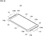
- FIG. 5 is a perspective view of a battery cell included in a battery module of an example.
- a battery module 100 may include a battery cell stack 120 in which a plurality of battery cells 110 are stacked along one direction, a module frame 200 accommodating the battery cell stack 120, a bus bar frame 300 positioned on the front surface and/or the rear surface of the battery cell stack 120, an end plate 400 covering the front surface and/or the rear surface of the battery cell stack 120, and bus bars 510 and 520 mounted on the bus bar frame 300.
- the battery cell 110 may be provided as a pouch-type in which the number of stacks per unit area may be maximized.
- the battery cell 110 provided as a pouch-type may be manufactured by accommodating an electrode assembly including a positive electrode, a negative electrode, and a separator in a cell case 114 of a laminate sheet, and then heat-sealing a sealing part of the cell case 114.
- the battery cell 110 does not necessarily have to be provided as the pouch-type, and may be provided in a prismatic, a cylindrical, or other various forms under a level at which a storage capacity required by a device to be mounted in the future is achieved.
- the battery cell 110 may include two electrode leads 111 and 112.
- the electrode leads 111 and 112 may have a structure protruded from one end of the cell body 113, respectively. Specifically, one end of each electrode lead 111 and 112 is electrically connected to the positive electrode or the negative electrode of the electrode assembly by being positioned inside the cell case 114, and the other end of each electrode lead 111 and 112 is positioned and derived outside the cell case 114 to be electrically connected to a separate member, for example, the bus bars 510 and 520.
- FIG. 4 shows that the positive electrode lead and the negative electrode lead of the battery cell 110 are protruded in opposite directions, but this is not necessarily the case, and it is possible that the electrode leads of the battery cell 110 may be protruded in the same direction.
- the electrode assembly in the cell case 114 may be sealed by sealing parts 114sa, 114sb, and 114sc.
- the sealing parts 114sa, 114sb, and 114sc of the cell case 114 may be positioned on both ends 114a and 114b, and one side 114c connecting them.
- the cell case 114 is generally composed of a laminate structure of a resin layer/a metal thin film layer/a resin layer.
- the cell case surface is made of an O (oriented)-nylon layer
- the battery cell stack 120 may be formed by attaching an adhesive member such as a viscous adhesive such as a double-sided adhesive tape to the surface of the cell case 114 or a chemical adhesive that is bonded by a chemical reaction during the adhesion.
- connection part 115 may refer to an area extending along the length direction from one end of the cell case 114 in which the above-described sealing parts 114sa, 114sb, and 114scare not positioned.
- a protrusion part 110p of the battery cell 110 called a bat-ear may be formed at the end of the connection part 115.
- a terrace portion 116 may refer to an area between the electrode leads 111 and 112, which are partially protruded to the outside of the cell case 114 and the cell body 113 positioned inside the cell case 114 based on the edge of the cell case 114.
- the battery cell stack 120 may be a plurality of battery cells 110 that are electrically connected and stacked in one direction.
- the direction in which a plurality of battery cells 110 are stacked (hereinafter, referred to as 'a stacking direction') may be a y-axis direction (or -y-axis direction), and 'an axis direction' may be construed as including all +/-directions below.
- the electrode leads of the battery cell 110 may be positioned on one surface, or one surface and the other surface facing the one surface of the battery cell stack 120.
- the surface on which the electrode leads 111 and 112 are positioned in the battery cell stack 120 may be referred to as the front surface or the rear surface of the battery cell stack 120
- the direction from the front surface to the rear surface of the battery cell stack 120, or the opposite direction may be defined as the length direction of the battery cell stack 120, and may be the x-axis direction.
- the length direction of the battery cell stack 120 may be substantially the same as the length direction of the battery cell 110.
- the surface on which the outermost battery cell 110 is positioned in the battery cell stack 120 may be referred to as a side surface of the battery cell stack 120, and the side surface of the battery cell stack 120 may be described as two surfaces facing each other on the y-axis.
- the module frame 200 may protect the battery cell stack 120 and the electrical equipment connected thereto from external physical impact.
- the module frame 200 may accommodate the battery cell stack 120 and the electronic devices connected thereto in the inner space of the module frame 200.
- the module frame 200 includes the inner surface and the outer surface, and the inner space of the module frame 200 may be defined by the inner surface.
- the structure of the module frame 200 may vary.
- the structure of the module frame 200 may be a structure of a mono frame.
- the mono frame may be in the form of a metal plate in which the upper surface, the lower surface, and both side surfaces are integrated.
- the mono frames may be manufactured by extrusion molding.
- the structure of the module frame 200 may be a structure in which a U-shaped frame and an upper plate (an upper surface) are combined.
- the structure of the module frame 200 may be formed by combining the upper plate with the upper side of the U-shaped frame, which is a metal plate having the lower surface and both side surfaces that are combined or integrated, and each frame or plate may be manufactured by press molding.
- the structure of the module frame 200 may be provided in the form of an L-shaped frame in addition to the mono frame or the U-shaped frame, or may be provided in various structures not described in the above-described example.
- the structure of the module frame 200 may be provided in an opened form along the length direction of the battery cell stack 120.
- the front and rear surfaces of the battery cell stack 120 may not be covered by the module frame 200.
- the front and rear surfaces of the battery cell stack 120 may be covered by the bus bar frame 300 or the end plate 400 to be described later, and through this, the front and rear surfaces of the battery cell stack 120 may be protected from external physical impact.
- the top/bottom surfaces, the front/rear surfaces, and both side surfaces of the module frame 200 may be described based on the contents of the battery cell stack 120 described above. Specifically, the top/bottom surfaces of the module frame 200 may be explained as two surfaces facing each other on the z-axis, the front/rear surfaces of the module frame 200 may be explained as two surfaces facing each other on the x-axis, and both side surfaces of the module frame 200 may be explained as two surfaces facing each other on the y-axis.
- the direction from the front to the rear or from the rear to the front may be the length direction of the module frame 200.
- a compressive pad may be positioned between the battery cell stack 120 and the inner surface of the module frame 200.
- the compressive pad may be positioned between the side of the battery cell stack 120 and the side of the module frame 200, and may face at least one of two battery cells 110 at both ends of the battery cell stack 120 with the surface.
- a thermal conductive resin may be injected between the battery cell stack 120 and the inner surface of the module frame 200, and a thermally conductive resin layer (not shown) may be formed between the battery cell stack 120 and the inner surface of the module frame 200 by the injected thermal conductive resin.
- the thermal conductive resin layer may be formed between the lower surface of the battery cell stack 120 and the lower surface of the module frame 200 (or the bottom surface, which may be referred to as a bottom part).
- the bus bar frame 300 may be positioned on one surface of the battery cell stack 120 to cover one surface of the battery cell stack 120 and to simultaneously guide the connection between the battery cell stack 120 and an external device.
- the bus bar frame 300 may be positioned on the front surface or the rear surface of the battery cell stack 120.
- the bus bar frame 300 may be equipped with at least one of the bus bars 510 and 520 and the module connector.
- One surface of the bus bar frame 300 may be connected to the front surface or the rear surface of the battery cell stack 120, and the other surface of the bus bar frame 300 may be connected to the bus bars 510 and 520.
- the bus bar frame 300 may include an electrically insulating material.
- the bus bar frame 300 may limit the contact of the bus bars 510 and 520 with parts of the battery cells 110 other than the parts joined to the electrode leads 111 and 112, and may prevent an electric short from occurring.
- the end plate 400 may close and seal the opened surface of the module frame 200 to protect the battery cell stack 120 and the electrical equipment connected thereto from an external physical impact.
- the end plate 400 may be made of a material having a predetermined strength.
- the end plate 400 may include a metal such as aluminum.
- the end plate 400 may be combined (bonded, sealed, or closed and sealed) with the module frame 200 while covering the bus bar frame 300 or the bus bars 510 and 520 positioned on one surface of the battery cell stack 120. Each edge of the end plate 400 may be joined with the corresponding edge of the module frame 200 by a method such as welding. Also, an insulating cover 700 for electrical insulation may be positioned between the end plate 400 and the bus bar frame 300. The insulating cover 700 may be positioned on the inner surface of the end plate 400 and may be closely attached to the inner surface of the end plate 400, but this is not necessarily the case.
- Two end plates 400 may be provided and may include a first end plate positioned on the front surface of the battery cell stack 120 and a second end plate positioned on the rear surface of the battery cell stack 120.
- the bus bars 510 and 520 may be mounted on one surface of the bus bar frame 300, and may be for electrically connecting the battery cell stack 120 or the battery cells 110, and an external device circuit. By positioning the bus bars 510 and 520 between the battery cell stack 120 or the bus bar frame 300 and the end plate 400, they may be protected from the external impact, and durability degradation due to external moisture may be minimized.
- the bus bars 510 and 520 may be electrically connected to the battery cell stack 120 through the electrode leads 111 and 112 of the battery cell 110.
- the electrode leads 111 and 112 of the battery cell 110 may be bent after passing through a slit formed in the bus bar frame 300 to be connected to the bus bars 510 and 520.
- the battery cells 110 constituting the battery cell stack 120 may be coupled in series or in parallel by the bus bars 510 and 520.
- the bus bars 510 and 520 may include a terminal bus bar 520 for forming an electrical connection between the battery modules 100. At least a part of the terminal bus bar 520 may be exposed to the outside of the end plate 400 in order to be connected to the external battery module 100, and the end plate 400 may be provided with a terminal bus bar opening 400H for this purpose.
- the terminal bus bar may be connected to another battery module 100 or a BDU (Battery Disconnect Unit) through the protrusion part exposed through the terminal bus bar opening 400H, and may form a high voltage (HV) connection with them.
- BDU Battery Disconnect Unit
- the battery module 100 may include a sensing member for detecting and controlling phenomena such as an overvoltage, an overcurrent, and overheating of the battery cell 110.
- the sensing member is for an LV (Low voltage) connection, where the LV connection may mean a sensing connection for sensing and controlling the voltage of the battery cell.
- a voltage information and a temperature information of the battery cell 110 may be transmitted to an external BMS (Battery Management System) through the sensing member.
- BMS Battery Management System
- the sensing member may include a temperature sensor that detects the temperature inside the battery module, a sensing terminal that senses the voltage value of the bus bars 510 and 520, a module connector that transmits the collected data to an external control device and receives a signal from an external control device, and/or a connection member for connecting them.
- connection member may be disposed in a form extending along the length direction on the upper surface of the battery cell stack 120, and may be a flexible printed circuit board (FPCB) or a flexible flat cable (FFC).
- FPCB flexible printed circuit board
- FFC flexible flat cable
- the module connector may be mounted on the above-described bus bar frame 300, and at least a part of the module connector may be exposed to the outside through the module connector opening formed on the end plate 400.
- an ignition phenomenon may occur inside the battery module 100 in which the battery cells 110 are stacked at a high density. If an ignition occurs in one battery module 100, heat, gas, or flame of the battery module 100 may be transferred to the adjacent battery module 100, so the continuous ignition may occur between the battery modules 100, and accordingly, there was a problem that the durability and stability of the battery module 100 or the battery pack including the same deteriorated.
- a cover layer 800 and a venting part 900 that may improve the durability and stability of the battery module 100 by solving the above ignition phenomenon are described.
- the module frame 200 may include a venting part 900 penetrating the inner surface and the outer surface of the module frame 200.
- the venting part 900 may have a hole shape that communicates with the inlet 900a formed on the inner surface of the module frame 200 and the outlet 900b formed on the outer surface of the module frame 200.
- the venting part 900 may be for communicating with the inside of the battery module 100 closed and sealed by the module frame 200 and the end plate 400, etc. and the outside of the battery module 100.
- the venting part 900 may be for discharging heat, gas, or flames generated when the battery module 100 internally ignites to the outside of the battery module 100.
- the venting part 900 may prevent the continuous thermal runaway phenomenon by alleviating the internal ignition of the module frame 200 and minimizing the rise in pressure or temperature. Specifically, when the ignition occurs inside the module frame 200, heat, gas, sparks, flames, etc. due to the ignition of the battery cell 110 are discharged to the outside of the battery module 100 through the venting part 900, so that the internal fire is quickly suppressed and the ignition phenomenon may be more relaxed. In addition, as heat, gas, etc. are discharged through the venting part 900, excessive increasing in pressure or temperature inside the battery module 100 may be prevented, and the speed at which the thermal runaway is transferred in the internal space may also be delayed.
- the venting part 900 may be formed on at least one surface of the module frame 200.
- the venting part 900 may be formed on a surface extending from the module frame 200 along the stacking direction or the length direction of the battery cell stack 120.
- venting parts 900 may be disposed by forming a row arranged along one direction and a column arranged along a direction perpendicular to the one direction. At this time, the venting part 900 may be formed entirely on one surface of the module frame 200 as in the drawings described above, but this is not always the case, and may be formed on a part of one surface of the module frame 200.
- the shape of the inlet 220a and the outlet 220b of the venting part 900 may be a rounded shape with a curvature as in the drawings described above, but this is not necessarily the case, and the inlet 220a and the outlet 220b of the venting part 900 may be provided as circular, elliptical, or polygonal with vertices.
- the size of the outlet 220b may be larger than the size of the inlet 220a.
- the direction from the inlet 220a to the outlet 220b of the venting part 900 may be a discharge direction in which gas inside the battery module 100 is discharged to the outside.
- the direction from the inlet 220a to the outlet 220b of the venting part 900 is shown to be perpendicular to one surface of the module frame 200 where the venting part 900 is formed, but this is not necessarily the case, and a hole structure may be formed by changing the positions of the inlet 220a and outlet 220b of the venting part 900 so that the discharge direction forms an acute angle with one surface of the module frame 200.
- the hole of the venting part 900 has an inclined structure, the exposure of the inside of the battery module 100 is minimized, and foreign substances floating in the air may be prevented from entering the battery module 100 by gravity.
- the discharge direction forms the angle (the acute angle) by changing the positions of the inlet 220a and the outlet 220b of the venting part 900
- the direction of heat, gas, or flame discharged from the venting part 900 may be switched (adjusted). Due to this, the length of the discharge path may increase, and the gas discharged through the outlet 220b of the venting part 900 may have a lower temperature.
- the discharge direction of the venting part 900 is formed in a direction in which the adjacent battery modules 100 are not positioned, heat propagation between the adjacent battery modules 100 may be minimized.
- the discharge directions of a plurality of venting parts 900 may be the same as or different from each other.
- gas discharged from the venting part 900 may be diffused into a wider space outside the battery module 100 in various directions. Accordingly, gas may be discharged from the battery module 100 quickly, and an effect such as preventing heat generation of the battery module 100 may be achieved.
- the venting part 900 for communicating with the inside and the outside is provided in the module frame 200 as in the present embodiment
- dust and impurities from the outside of the module frame 200 may enter the inside of the module frame 200 through the hole structure of the venting part 900, or external oxygen is supplied along the venting part 900 during the internal ignition, thereby a thermal runaway phenomenon may be promoted.
- the gas, spark, etc. discharged through the venting part 900 of the module frame 200 may be in a very high temperature and pressure state, the discharged gas, spark, etc. are transferred to the adjacent battery module 100 and there is a problem that the thermally runaway phenomenon in the adjacent battery module 100 is caused.
- a cover layer 800 may be provided to close the hole before the thermal runaway phenomenon occurs, and to open the hole when the thermal runaway phenomenon occurs, thereby slightly lowering the temperature and pressure of the emitted gas.
- the battery module 100 may include a cover layer 800 covering the opening of the hole structure of the venting part 900.
- the cover layer 800 may be positioned under the module frame 200 where the venting part 900 is formed or one surface of the end plate 400.
- the cover layer 800 may include a plurality of layers.
- the cover layer 800 may include a barrier layer 810 that may be partially fractured by heat or pressure and refractory layers 820 and 830 made of a refractory material capable of withstanding a predetermined temperature or pressure.
- the barrier layer 810 may be positioned closer to the battery cell stack 120 than the refractory layers 820 and 830, and when considering the positions, the barrier layer 810 may be referred to as a first layer and the refractory layers 820 and 830 may be referred to as a second layer.
- the refractory layer may include two or more layers as shown in FIG.
- the layer positioned relatively close to the barrier layer 810 may be referred to as a first refractory layer 820 and the layer positioned farther from the barrier layer 810 may be referred to as a second refractory layer 830.
- the barrier layer 810 may be referred to as a first layer
- the first refractory layer 820 may be referred to as a second layer
- the second refractory layer 830 may be referred to as a third layer.
- a plurality of venting parts may be formed in the refractory layers 820 and 830.
- the venting parts formed in the refractory layers 820 and 830 may be referred to as sub-venting parts 822 and 832.
- Each sub-venting part 822 and 832 may have an inlet and an outlet, and the inlet may be positioned relatively below the outlet.
- the sub-venting parts 822 and 832 formed in the refractory layers 820 and 830 may guide the discharge path of the gas so that the gas, sparks, etc. generated in the battery cell 110 are discharged to the venting part 900 without moving to other spaces in the battery module 100.
- the refractory layers 820 and 830 may be made of a material that may withstand a high temperature and high pressure environment for a certain period of time.
- the refractory layers 820 and 830 may be made of aluminum, stainless use steel (SUS), or a clad metal.
- the refractory layers 820 and 830 may be injection moldings that may withstand a high temperature and high pressure environment for a certain period of time.
- the barrier layer 810 is positioned between the refractory layers 820 and 830, and the battery cell stack 120, and prevents foreign materials from being injected into the battery module 100 before the thermal runaway occurs in the battery module 100, and is removed by heat or pressure after the runaway phenomenon occurs, thereby the venting part 900 and the sub-venting part 822 and 832 may be opened.
- the upper surface of the barrier layer 810 may be partially protruded, and the protruded portion is inserted into the first sub-venting part 822 formed in the first refractory layer 820, thereby minimizing the inflow of foreign material into the battery module 100.
- the barrier layer 810 may include a material that is melted by the internal temperature of the battery module 100.
- the barrier layer 810 may include a material melted by heat emitted from the battery cell 110, high temperature gas, or sparks.
- the barrier layer 810 may be made of a material having a melting point of less than or equal to a predetermined range.
- the barrier layer 810 may be provided with a material having a melting point of 300 °C or less.
- the barrier layer 810 may include a thermoplastic polymer resin having a melting point of about 200 °C or less. More specifically, the barrier layer 810 may be made of materials having a melting point of about 100 °C or more and 200 °C or less, such as polyethylene or polypropylene.
- the barrier layer 810 may include a material for alleviating the ignition phenomenon when the battery module 100 internally ignites.
- the barrier layer 810 may include a fire extinguishing agent. If the barrier layer 810 includes an extinguishing agent, the battery module 100 may have a self-extinguishing function.
- the extinguishing agent may be a powder-type extinguishing agent material. The extinguishing agent may generate carbon dioxide and water vapor through a thermal decomposition reaction when the battery module 100 is ignited, and the generated carbon dioxide and water vapor may suppress the flame by preventing external oxygen from flowing into the battery module 100.
- the extinguishing agent may absorb the heat generated in the battery module by performing the pyrolysis reaction, which is an endothermic reaction, and may also block the external oxygen supply by generating carbon dioxide and water vapor. Accordingly, the flame and heat propagation speed inside the battery module 100 may be effectively delayed, and the safety of the battery module may be improved.
- the barrier layer 810 may include at least one extinguishing agent selected from a group consisting of inorganic carbonates, inorganic phosphates, and inorganic sulfates. More specific examples of the extinguishing agent materials may include sodium hydrogen carbonate (NaHCOs), potassium hydrogen carbonate (KHCOs), ammonium phosphate (NH 4 H 2 PO 3 ), and a mixture of "potassium hydrogen carbonate (KHCOs) and urea (NH 22 CO)".
- the cover layer 800 includes potassium hydrogen carbonate (KHCOs), potassium carbonate (K 2 CO 3 ), water vapor (H 2 O), and carbon dioxide (CO 2 ) may be generated through the pyrolysis reaction of potassium hydrogen carbonate.
- the extinguishing agent material of the present embodiment is not limited thereto, and if it is a material that performs a fire extinguishing function, it will be available without limitation.
- the barrier layer 810 may be manufactured and provided with materials having the above-described properties, but may also be provided as a material including a plurality of properties or a composite of materials including each property.
- FIG. 6 is a cross-sectional view taken along a cutting line B-B of FIG. 3 .
- FIG. 7 is a cross-sectional view taken along a cutting line C-C of FIG. 3 .
- FIG. 8 is a view showing an internal ignition of a battery module according to FIG. 3 .
- FIG. 6 shows the cross-section on the length direction of the battery module 100
- FIG. 7 shows the cross-section on the width direction of the battery module 100.
- At least a part of the venting part 900 formed in the module frame 200 and the sub-venting part 822 and 832 formed in the refractory layers 820 and 830 may be overlapped on the length direction (the x-axis) of the battery module 100. At least a part of the venting part 900 and the sub-venting parts 822 and 832 may be overlapped in the width direction (the y-axis) of the battery module 100.
- At least part of the venting part 900 formed in the module frame 200 and the second sub-venting part 832 formed in the second refractory layer 830, or the first sub-venting part 822 formed in the second sub-venting part 832 and the first refractory layer 820, may overlap in the length direction (the x-axis) of the battery module 100. At least a portion of the venting part 900 and the second sub-venting part 832, or the second sub-venting part 832 and the first sub-venting part 822, may be overlapped in the width direction (the y-axis).
- the path of gas discharged to the outside of the battery module 100 through the hole may be switched.
- the path through which gas is discharged may form an angle with the z-axis.
- the path through which gas is discharged may be formed in a zigzag shape. Since the holes formed in the module frame 200 and the refractory layers 820 and 830 do not completely correspond to each other, the discharge path may be longer than in the case where the holes correspond to each other.
- the gas discharge path may be longer than the shortest distance between the upper surface of the battery cell stack 120 and the module frame 200. As the discharge path of the gas becomes somewhat longer, the temperature and pressure of the gas discharged to the outside of the battery module 100 may be further lowered, and energy may be low enough to not affect the adjacent battery module 100.
- venting parts 900 and the sub-venting parts 822 and 832 formed in the module frame 200 and the refractory layers 820 and 830 may have a structure of an inclined hole. If the holes of each venting part 900 and sub-venting parts 822 and 832 are formed to form the acute angle with one surface of the module frame 200, the above-described switching of the discharge path may be implemented more effectively.
- the barrier layer 810 around the ignition phenomenon is physically torn or chemically melted and penetrated by heat or pressure (penetrating), and thus the venting part 900 and/or the sub-venting part 822, and 832 may be opened. Heat, gas, or sparks inside the battery module 100 may be discharged through the opened venting part 900 and sub-venting parts 822 and 832, and the ignition phenomenon of the battery module 100 may be alleviated.
- the process in which the barrier layer 810 is penetrated, that is, opened, may accompany an endothermic reaction, and the temperature inside the battery module 100 may be somewhat lowered by the barrier layer 810 absorbing the internal heat. Heat, gas, etc. emitted to the outside of the venting part 900 through the endothermic reaction of the barrier layer 810 may lose the energy enough to not affect the adjacent battery module 100, and the spark loses energy and is transformed into particles, thereby the thermal runaway of the adjacent battery module 100 may not be promoted.
- the barrier layer 810 is opened through the chemical reaction for the effect of the barrier layer 810, even when the barrier layer 810 is physically opened by pressure, etc., since the kinetic energy of gas or spark is reduced in the process of removing the barrier layer 810, heat, gas, etc. emitted to the outside of the battery module 100 may lose the energy enough to not affect the adjacent battery module 100, and the spark may lose energy and become particles, which may not promote the thermal runaway phenomenon of the adjacent battery module 100.
- the barrier layer 810 may be opened only when heat or pressure over a predetermined range is applied, only the barrier layer 810 positioned around the ignition phenomenon may be opened individually.
- the barrier layer 810 may prevent the promotion of the thermal runaway phenomenon due to additional oxygen inflow as only a portion of a plurality of venting parts 900 and sub-venting parts 822 and 832 is opened.
- the first portion 810a of the barrier layer 810 corresponding to the first battery cell 110a is opened, so that gas, flame, etc. generated in the first battery cell 110a may be discharged.
- the second part 810b of the barrier layer 810 positioned above the second battery cell 110b in which the ignition phenomenon has not occurred in the battery module 100 may not be opened, and the first sub-venting part 822 corresponding to the second part 810b may be in the closed state.
- the additional inflow of external oxygen into the battery module 100 may be blocked as the closed state of the barrier layer 810 of the other part where the ignition phenomenon does not occur is maintained, so the amplification of the flame generated inside the battery module 100 by inflowed oxygen may be suppressed.
- the barrier layer 810 may include a protrusion part 812 partially protruded from one surface of the barrier layer 810.
- the protrusion part 812 may be formed on the upper surface of the barrier layer 810.
- the size of the protrusion part 812 may be similar to or smaller than the size of the first sub-venting part 822, through which the protrusion part 812 may be inserted into the first sub-venting part 822 formed in the first refractory layer 820.
- the outer shape of the protrusion part 812 may correspond to the inner shape of the first sub-venting part 822, whereby the hole of the first sub-venting part 822 may be closed by the protrusion part 812.
- the region where the protrusion part 812 is formed in the barrier layer 810 may have a rather thick thickness.
- the protrusion part 812 is formed on the barrier layer 810, the space occupied by the barrier layer 810 inside the battery module 100 is the same, but since the rather thick barrier layer 810 has to be opened for the battery module 100 to emit gas to the outside, the fire suppression effect by the barrier layer 810 may be greater.
- this is not necessarily the case, and it is possible that the protrusion part 812 is not formed on the barrier layer 810 and that the barrier layer 810 has a flat shape.
- the battery pack may have a structure in which one or more battery modules according to the present embodiment are added, and may have a structure in a battery management system (BMS) and a cooling device that manage the temperature or voltage of the battery are added and packed.
- BMS battery management system
- the above-described battery module and the battery pack including the same can be applied to various devices.
- a device may be applied to transportation means such as an electric bicycle, an electric vehicle, a hybrid vehicle, etc., but the present invention is not limited thereto, and is applicable to various devices that can use a battery module, which is also within the scope of the present invention.
- the present invention may be further embodied by the following examples.
- a battery module may comprise a battery cell stack, a module frame and a cover layer.
- a battery cell stack a plurality of battery cells may be stacked in one direction.
- the module frame may accommodate the battery cell stack and may have an inner surface and an outer surface. At least one venting part may penetrate the inner surface and the outer surface and may be formed on one surface of the module frame.
- the cover layer may include a barrier layer and a refractory layer and may be positioned between the one surface of the module frame where the venting part is formed and the battery cell stack.
- Example 2 The battery module of Example 1, wherein the venting part may be formed on the upper surface of the module frame.
- Example 3 The battery module of Example 1, the barrier layer may be positioned below the refractory layer.
- Example 4 The battery module of Example 1, the refractory layer may include at least one sub-venting part.
- Example 5 The battery module of Example 4, wherein the barrier layer may cover a hole of the sub-venting part.
- Example 6 The battery module of Example 4, wherein the barrier layer may include a protrusion part partially protruded from one surface of the barrier layer. The protrusion part may be inserted into the sub-venting part.
- Example 7 The battery module of Example 4, wherein the at least parts of the venting part and the sub-venting part may overlap in the length direction of the battery module.
- Example 8 The battery module of Example 4, wherein at least parts of the venting part and the sub-venting part may overlap in the width direction of the battery module.
- Example 9 The battery module of Example 4, wherein the hole of the sub-venting part or the venting part may form an acute angle with one surface of the module frame.
- Example 10 The battery module of Example 1, wherein the refractory layer may include a first refractory layer and a second refractory layer.
- the first refractory layer may be positioned closer to the barrier layer than the second refractory layer.
- Example 11 The battery module of Example 10, wherein the first refractory layer may include at least one first sub-venting part.
- the second refractory layer may include at least one second sub-venting part.
- Example 12 The battery module of Example 11, wherein at least parts of the first sub-venting part and the second sub-venting part may overlap in a length direction of the battery module.
- Example 13 The battery module of Example 11, wherein at least parts of the first sub-venting part and the second sub-venting part may overlap in a width direction of the battery module.
- Example 14 The battery module of Example 1, wherein the barrier layer may include a material with a melting point of about 300 °C or less.
- Example 15 The battery module of Example 1, wherein the barrier layer may include at least one extinguishing agent selected from a group consisting of inorganic carbonates, inorganic phosphates, and inorganic sulfates.
- Example 16 The battery module of Example 1, wherein the refractory layer may include aluminum, SUS (Stainless Use Steel), or a clad metal.
- the refractory layer may include aluminum, SUS (Stainless Use Steel), or a clad metal.
- Example 17 A battery pack which includes at least one battery module as disclosed herein.
Landscapes
- Chemical & Material Sciences (AREA)
- Chemical Kinetics & Catalysis (AREA)
- Electrochemistry (AREA)
- General Chemical & Material Sciences (AREA)
- Inorganic Chemistry (AREA)
- Public Health (AREA)
- Health & Medical Sciences (AREA)
- Business, Economics & Management (AREA)
- Emergency Management (AREA)
- Battery Mounting, Suspending (AREA)
- Gas Exhaust Devices For Batteries (AREA)
- Engineering & Computer Science (AREA)
- Manufacturing & Machinery (AREA)
Abstract
Description
- This application claims priority to and the benefit of
Korean Patent Application No. 10-2021-0089269 filed in the Korean Intellectual Property Office on July 07, 2021 - The present invention relates to a battery module and a battery pack including the same, and more specifically to a battery module with enhanced safety and a battery pack including the same.
- As development of technologies and demands for mobile devices are increased, there is a rapidly increasing demand for rechargeable batteries as energy sources. Accordingly, many studies have been conducted on secondary batteries that can meet various needs.
- The rechargeable batteries are attracting a lot of attention as an energy source for power devices, such as electric bicycles, electric vehicles, and hybrid electric vehicles, as well as mobile devices, such as mobile phones, digital cameras, and notebook computers.
- Recently, as the need for a large capacity rechargeable battery structure, including the use of rechargeable batteries as an energy storage source, increases, the demand for a battery pack with a multi-module structure in which a plurality of rechargeable batteries are assembled in series/coupled in parallel battery modules is increasing. The battery pack consists mainly of a battery module composed of at least one battery cell, and is composed by adding other constituent elements by using at least one battery module. Since the battery cells constituting the battery module are composed of a chargeable and dischargeable rechargeable battery, such a high power/large capacity rechargeable battery generates a large amount of heat during charge and discharge processes.
-
FIG. 1 is an exploded perspective view of a conventional battery module.FIG. 2 is a view showing a spread of a thermal runaway phenomenon during internal ignition of a conventional battery module. - Referring to
FIG. 1 andFIG. 2 , aconventional battery module 10 includes abattery cell stack 12 in which a plurality ofbattery cells 11 is stacked, aframe 20 receiving thebattery cell stack 12, andend plates 40 formed on the front and rear surfaces of thebattery cell stack 12. - The
battery cell stack 12 may be positioned in a closed and sealed structure by combining theframe 20 and theend plate 40. At this time, theframe 20 may have an empty interior space like the incision surface A-A ofFIG. 1 , and thebattery cells 11 may be stacked in one direction and positioned in the empty interior space of theframe 20 as shown inFIG. 2 . - On the other hand, since a plurality of
battery cells 11 are located densely in one space without being isolated from each other in theframe 20, even if the thermal runaway phenomenon occurs only in one of a plurality ofbattery cells 11 present in theframe 20 due to an overcharge, etc., the thermal runaway phenomenon may be rapidly transferred to the otheradjacent battery cells 11. - Moreover, since a plurality of
battery modules 10 in the battery pack are disposed so that at least twoend plates 40 face each other, when heat, gas, or flame generated in thebattery module 10 is discharged to the outside of thebattery module 10, It may affect the performance and stability of a plurality ofbattery cells 11 in the otheradjacent battery modules 10. - Therefore, it is necessary to develop the
battery module 10 with improved durability and safety by effectively delaying the heat propagation speed during the internal ignition of thebattery module 10 and allowing the generated heat, gas, or flame to be rapidly discharged to the outside of thebattery module 10. - The problem to be solved by the present invention is to provide a battery module that prevents the transfer of the thermal runaway phenomenon between the battery cells when the ignition occurs in the battery module and a battery pack including the same.
- However, the problems to be solved by the embodiments of the present invention are not limited to the above-described problems and may be variously expanded in the range of the technical ideas included in the present invention.
- The present invention is defined by the subject matter of the appended independent claim. Particular embodiments are given by the features of the appended dependent claims. A battery module may include: a battery cell stack in which a plurality of battery cells are stacked in one direction; and a module frame accommodating the battery cell stack and having an inner surface and an outer surface, wherein at least one venting part penetrating the inner surface and the outer surface is formed on one surface of the module frame, and a cover layer including a barrier layer and a refractory layer is positioned between one surface of the module frame where the venting part is formed and the battery cell stack.
- The venting part may be formed on the upper surface of the module frame.
- The barrier layer may be positioned below the refractory layer.
- The refractory layer may include at least one sub-venting part.
- The barrier layer may cover a hole of the sub-venting part.
- The barrier layer may include a protrusion part partially protruded from one surface of the barrier layer, and the protrusion part may be inserted into the sub-venting part.
- At least parts of the venting part and the sub-venting part may overlap in the length direction of the battery module.
- At least parts of the venting part and the sub-venting part may overlap in the width direction of the battery module.
- The hole of the sub-venting part or the venting part may form an acute angle with one surface of the module frame.
- The refractory layer may include a first refractory layer and a second refractory layer, and the first refractory layer may be positioned closer to the barrier layer than the second refractory layer.
- The first refractory layer may include at least one first sub-venting part, and the second refractory layer may include at least one second sub-venting part.
- At least parts of the first sub-venting part and the second sub-venting part may overlap in the length direction of the battery module.
- At least parts of the first sub-venting part and the second sub-venting part may overlap in the width direction of the battery module.
- The barrier layer may include a material with a melting point of about 300 °C or less.
- The barrier layer may include at least one extinguishing agent selected from a group consisting of inorganic carbonates, inorganic phosphates, and inorganic sulfates.
- The refractory layer may include aluminum, SUS (Stainless Use Steel), or a clad metal.
- A battery pack according to another embodiment of the present invention includes the above-described battery module.
- According to embodiments, a continuous thermal runaway phenomenon inside the battery module may be prevented by rapidly discharging a gas or the like to the outside of the battery module through a hole in the module frame when an ignition phenomenon occurs in the battery module.
- The effects of the present invention are not limited to the foregoing effects, and other non-mentioned effects will be clearly understood by those skilled in the art from the description below.
-
-
FIG. 1 is an exploded perspective view of a conventional battery module. -
FIG. 2 is a view showing a transfer of a thermal runaway phenomenon during internal ignition of a conventional battery module. -
FIG. 3 is a perspective view showing a battery module according to an embodiment of the present invention. -
FIG. 4 is an exploded perspective view of a battery module according toFIG. 3 . -
FIG. 5 is a perspective view of a battery cell included in a battery module ofFIG. 3 . -
FIG. 6 is a cross-sectional view taken along a cutting line B-B ofFIG. 3 . -
FIG. 7 is a cross-sectional view taken along a cutting line C-C ofFIG. 3 . -
FIG. 8 is a view showing an internal ignition of a battery module according toFIG. 3 . - The present invention will be described more fully hereinafter with reference to the accompanying drawings, in which embodiments of the invention are shown. As those skilled in the art would realize, the described embodiments may be modified in various different ways, all without departing from the spirit or scope of the present invention.
- In order to clarify the present invention, parts that are not connected to the description will be omitted, and the same elements or equivalents are referred to by the same reference numerals throughout the specification.
- In addition, since the size and thickness of each component shown in the drawing are arbitrarily enlarged or reduced for convenience of explanation, it is self-evident that the content of the present invention is not limited to as shown. In the drawing below, the thickness of each layer is enlarged to clearly express various layers and areas. Also, in the following drawings, for convenience of explanation, the thicknesses of some layers and areas are exaggerated.
- It will be understood that when an element such as a layer, film, region, or substrate is referred to as being "on" another element, it can be directly on the other element or intervening elements may also be present. By contrast, it will be understood that when an element is referred to as being "directly on" another element, no intervening elements are present. Further, in the specification, the word "on" or "above" means positioned on or below the object portion, and does not necessarily mean positioned on the upper side of the object portion based on a gravitational direction. On the other hand, when explaining that something is "on" or "above" another part, explaining being "under" or "below" another part may also be understood with reference to the above description.
- In addition, since an upper surface/a lower surface of a specific member may be determined differently depending on which direction is referenced, throughout the specification, 'the upper surface' or 'the lower surface' means two surfaces facing each other on a z-axis of the member.
- In addition, unless explicitly described to the contrary, the word "comprise", and variations such as "comprises" or "comprising", will be understood to imply the inclusion of stated elements but not the exclusion of any other elements.
- Further, in the specification, the phrase "on a plane" means when an object portion is viewed from above, and the phrase "on a cross-section" means when a cross-section taken by vertically cutting an object portion is viewed from the side.
- Hereinafter, a battery module according to an embodiment of the present invention is described.
-
FIG. 3 is a perspective view showing a battery module according to an example.FIG. 4 is an exploded perspective view of a battery module according to an example.FIG. 5 is a perspective view of a battery cell included in a battery module of an example. - Referring to
FIG. 3 andFIG. 4 , abattery module 100 according to an example may include abattery cell stack 120 in which a plurality ofbattery cells 110 are stacked along one direction, amodule frame 200 accommodating thebattery cell stack 120, abus bar frame 300 positioned on the front surface and/or the rear surface of thebattery cell stack 120, anend plate 400 covering the front surface and/or the rear surface of thebattery cell stack 120, andbus bars bus bar frame 300. - Referring to
FIG. 5 , thebattery cell 110 may be provided as a pouch-type in which the number of stacks per unit area may be maximized. Thebattery cell 110 provided as a pouch-type may be manufactured by accommodating an electrode assembly including a positive electrode, a negative electrode, and a separator in acell case 114 of a laminate sheet, and then heat-sealing a sealing part of thecell case 114. However, thebattery cell 110 does not necessarily have to be provided as the pouch-type, and may be provided in a prismatic, a cylindrical, or other various forms under a level at which a storage capacity required by a device to be mounted in the future is achieved. - The
battery cell 110 may include two electrode leads 111 and 112. The electrode leads 111 and 112 may have a structure protruded from one end of thecell body 113, respectively. Specifically, one end of eachelectrode lead cell case 114, and the other end of eachelectrode lead cell case 114 to be electrically connected to a separate member, for example, the bus bars 510 and 520. On the other hand,FIG. 4 shows that the positive electrode lead and the negative electrode lead of thebattery cell 110 are protruded in opposite directions, but this is not necessarily the case, and it is possible that the electrode leads of thebattery cell 110 may be protruded in the same direction. - The electrode assembly in the
cell case 114 may be sealed by sealing parts 114sa, 114sb, and 114sc. The sealing parts 114sa, 114sb, and 114sc of thecell case 114 may be positioned on bothends side 114c connecting them. - The
cell case 114 is generally composed of a laminate structure of a resin layer/a metal thin film layer/a resin layer. For example, when the cell case surface is made of an O (oriented)-nylon layer, when a plurality ofbattery cells 110 are stacked to form a medium orlarge battery module 100, there is a tendency to slide easily due to an external impact. Therefore, in order to prevent this and maintain the stable stacked structure of thebattery cells 110, thebattery cell stack 120 may be formed by attaching an adhesive member such as a viscous adhesive such as a double-sided adhesive tape to the surface of thecell case 114 or a chemical adhesive that is bonded by a chemical reaction during the adhesion. - The
connection part 115 may refer to an area extending along the length direction from one end of thecell case 114 in which the above-described sealing parts 114sa, 114sb, and 114scare not positioned. Aprotrusion part 110p of thebattery cell 110 called a bat-ear may be formed at the end of theconnection part 115. In addition, aterrace portion 116 may refer to an area between the electrode leads 111 and 112, which are partially protruded to the outside of thecell case 114 and thecell body 113 positioned inside thecell case 114 based on the edge of thecell case 114. - The
battery cell stack 120 may be a plurality ofbattery cells 110 that are electrically connected and stacked in one direction. The direction in which a plurality ofbattery cells 110 are stacked (hereinafter, referred to as 'a stacking direction') may be a y-axis direction (or -y-axis direction), and 'an axis direction' may be construed as including all +/-directions below. - Meanwhile, as the
battery cell 110 is disposed along one direction, the electrode leads of thebattery cell 110 may be positioned on one surface, or one surface and the other surface facing the one surface of thebattery cell stack 120. As such, the surface on which the electrode leads 111 and 112 are positioned in thebattery cell stack 120 may be referred to as the front surface or the rear surface of thebattery cell stack 120, the direction from the front surface to the rear surface of thebattery cell stack 120, or the opposite direction may be defined as the length direction of thebattery cell stack 120, and may be the x-axis direction. The length direction of thebattery cell stack 120 may be substantially the same as the length direction of thebattery cell 110. - In addition, the surface on which the
outermost battery cell 110 is positioned in thebattery cell stack 120 may be referred to as a side surface of thebattery cell stack 120, and the side surface of thebattery cell stack 120 may be described as two surfaces facing each other on the y-axis. - The
module frame 200 may protect thebattery cell stack 120 and the electrical equipment connected thereto from external physical impact. Themodule frame 200 may accommodate thebattery cell stack 120 and the electronic devices connected thereto in the inner space of themodule frame 200. Here, themodule frame 200 includes the inner surface and the outer surface, and the inner space of themodule frame 200 may be defined by the inner surface. - The structure of the
module frame 200 may vary. For example, the structure of themodule frame 200 may be a structure of a mono frame. Here, the mono frame may be in the form of a metal plate in which the upper surface, the lower surface, and both side surfaces are integrated. The mono frames may be manufactured by extrusion molding. As another example, the structure of themodule frame 200 may be a structure in which a U-shaped frame and an upper plate (an upper surface) are combined. In the case of the structure in which the U-shaped frame and the upper plate are combined, the structure of themodule frame 200 may be formed by combining the upper plate with the upper side of the U-shaped frame, which is a metal plate having the lower surface and both side surfaces that are combined or integrated, and each frame or plate may be manufactured by press molding. In addition, the structure of themodule frame 200 may be provided in the form of an L-shaped frame in addition to the mono frame or the U-shaped frame, or may be provided in various structures not described in the above-described example. - The structure of the
module frame 200 may be provided in an opened form along the length direction of thebattery cell stack 120. The front and rear surfaces of thebattery cell stack 120 may not be covered by themodule frame 200. The front and rear surfaces of thebattery cell stack 120 may be covered by thebus bar frame 300 or theend plate 400 to be described later, and through this, the front and rear surfaces of thebattery cell stack 120 may be protected from external physical impact. - The top/bottom surfaces, the front/rear surfaces, and both side surfaces of the
module frame 200 may be described based on the contents of thebattery cell stack 120 described above. Specifically, the top/bottom surfaces of themodule frame 200 may be explained as two surfaces facing each other on the z-axis, the front/rear surfaces of themodule frame 200 may be explained as two surfaces facing each other on the x-axis, and both side surfaces of themodule frame 200 may be explained as two surfaces facing each other on the y-axis. Here, the direction from the front to the rear or from the rear to the front may be the length direction of themodule frame 200. - Meanwhile, although not shown, a compressive pad may be positioned between the
battery cell stack 120 and the inner surface of themodule frame 200. At this time, the compressive pad may be positioned between the side of thebattery cell stack 120 and the side of themodule frame 200, and may face at least one of twobattery cells 110 at both ends of thebattery cell stack 120 with the surface. - In addition, a thermal conductive resin may be injected between the
battery cell stack 120 and the inner surface of themodule frame 200, and a thermally conductive resin layer (not shown) may be formed between thebattery cell stack 120 and the inner surface of themodule frame 200 by the injected thermal conductive resin. At this time, the thermal conductive resin layer may be formed between the lower surface of thebattery cell stack 120 and the lower surface of the module frame 200 (or the bottom surface, which may be referred to as a bottom part). - The
bus bar frame 300 may be positioned on one surface of thebattery cell stack 120 to cover one surface of thebattery cell stack 120 and to simultaneously guide the connection between thebattery cell stack 120 and an external device. Thebus bar frame 300 may be positioned on the front surface or the rear surface of thebattery cell stack 120. Thebus bar frame 300 may be equipped with at least one of the bus bars 510 and 520 and the module connector. One surface of thebus bar frame 300 may be connected to the front surface or the rear surface of thebattery cell stack 120, and the other surface of thebus bar frame 300 may be connected to the bus bars 510 and 520. There may be two bus bar frames 300, and they may be positioned on the front and rear surfaces of thebattery cell stack 120, respectively. - The
bus bar frame 300 may include an electrically insulating material. Thebus bar frame 300 may limit the contact of the bus bars 510 and 520 with parts of thebattery cells 110 other than the parts joined to the electrode leads 111 and 112, and may prevent an electric short from occurring. - The
end plate 400 may close and seal the opened surface of themodule frame 200 to protect thebattery cell stack 120 and the electrical equipment connected thereto from an external physical impact. To this end, theend plate 400 may be made of a material having a predetermined strength. For example, theend plate 400 may include a metal such as aluminum. - The
end plate 400 may be combined (bonded, sealed, or closed and sealed) with themodule frame 200 while covering thebus bar frame 300 or the bus bars 510 and 520 positioned on one surface of thebattery cell stack 120. Each edge of theend plate 400 may be joined with the corresponding edge of themodule frame 200 by a method such as welding. Also, an insulatingcover 700 for electrical insulation may be positioned between theend plate 400 and thebus bar frame 300. The insulatingcover 700 may be positioned on the inner surface of theend plate 400 and may be closely attached to the inner surface of theend plate 400, but this is not necessarily the case. - Two
end plates 400 may be provided and may include a first end plate positioned on the front surface of thebattery cell stack 120 and a second end plate positioned on the rear surface of thebattery cell stack 120. - The bus bars 510 and 520 may be mounted on one surface of the
bus bar frame 300, and may be for electrically connecting thebattery cell stack 120 or thebattery cells 110, and an external device circuit. By positioning the bus bars 510 and 520 between thebattery cell stack 120 or thebus bar frame 300 and theend plate 400, they may be protected from the external impact, and durability degradation due to external moisture may be minimized. - The bus bars 510 and 520 may be electrically connected to the
battery cell stack 120 through the electrode leads 111 and 112 of thebattery cell 110. Specifically, the electrode leads 111 and 112 of thebattery cell 110 may be bent after passing through a slit formed in thebus bar frame 300 to be connected to the bus bars 510 and 520. Thebattery cells 110 constituting thebattery cell stack 120 may be coupled in series or in parallel by the bus bars 510 and 520. - Meanwhile, the bus bars 510 and 520 may include a
terminal bus bar 520 for forming an electrical connection between thebattery modules 100. At least a part of theterminal bus bar 520 may be exposed to the outside of theend plate 400 in order to be connected to theexternal battery module 100, and theend plate 400 may be provided with a terminalbus bar opening 400H for this purpose. The terminal bus bar may be connected to anotherbattery module 100 or a BDU (Battery Disconnect Unit) through the protrusion part exposed through the terminalbus bar opening 400H, and may form a high voltage (HV) connection with them. - Although not shown, the
battery module 100 may include a sensing member for detecting and controlling phenomena such as an overvoltage, an overcurrent, and overheating of thebattery cell 110. The sensing member is for an LV (Low voltage) connection, where the LV connection may mean a sensing connection for sensing and controlling the voltage of the battery cell. A voltage information and a temperature information of thebattery cell 110 may be transmitted to an external BMS (Battery Management System) through the sensing member. - The sensing member may include a temperature sensor that detects the temperature inside the battery module, a sensing terminal that senses the voltage value of the bus bars 510 and 520, a module connector that transmits the collected data to an external control device and receives a signal from an external control device, and/or a connection member for connecting them.
- Here, the connection member may be disposed in a form extending along the length direction on the upper surface of the
battery cell stack 120, and may be a flexible printed circuit board (FPCB) or a flexible flat cable (FFC). - Also, here, the module connector may be mounted on the above-described
bus bar frame 300, and at least a part of the module connector may be exposed to the outside through the module connector opening formed on theend plate 400. - Meanwhile, as described above, an ignition phenomenon may occur inside the
battery module 100 in which thebattery cells 110 are stacked at a high density. If an ignition occurs in onebattery module 100, heat, gas, or flame of thebattery module 100 may be transferred to theadjacent battery module 100, so the continuous ignition may occur between thebattery modules 100, and accordingly, there was a problem that the durability and stability of thebattery module 100 or the battery pack including the same deteriorated. - Therefore, hereinafter, a
cover layer 800 and a ventingpart 900 that may improve the durability and stability of thebattery module 100 by solving the above ignition phenomenon are described. - Again referring to
FIG. 3 andFIG. 4 , themodule frame 200 according to an embodiment of the present invention may include a ventingpart 900 penetrating the inner surface and the outer surface of themodule frame 200. The ventingpart 900 may have a hole shape that communicates with theinlet 900a formed on the inner surface of themodule frame 200 and theoutlet 900b formed on the outer surface of themodule frame 200. The ventingpart 900 may be for communicating with the inside of thebattery module 100 closed and sealed by themodule frame 200 and theend plate 400, etc. and the outside of thebattery module 100. - The venting
part 900 may be for discharging heat, gas, or flames generated when thebattery module 100 internally ignites to the outside of thebattery module 100. The ventingpart 900 may prevent the continuous thermal runaway phenomenon by alleviating the internal ignition of themodule frame 200 and minimizing the rise in pressure or temperature. Specifically, when the ignition occurs inside themodule frame 200, heat, gas, sparks, flames, etc. due to the ignition of thebattery cell 110 are discharged to the outside of thebattery module 100 through the ventingpart 900, so that the internal fire is quickly suppressed and the ignition phenomenon may be more relaxed. In addition, as heat, gas, etc. are discharged through the ventingpart 900, excessive increasing in pressure or temperature inside thebattery module 100 may be prevented, and the speed at which the thermal runaway is transferred in the internal space may also be delayed. - The venting
part 900 may be formed on at least one surface of themodule frame 200. The ventingpart 900 may be formed on a surface extending from themodule frame 200 along the stacking direction or the length direction of thebattery cell stack 120. - The greater the number of venting
parts 900 formed in themodule frame 200, the faster the ignition phenomenon of themodule frame 200 may be alleviated. When there are a plurality of ventingparts 900, the ventingparts 900 may be disposed by forming a row arranged along one direction and a column arranged along a direction perpendicular to the one direction. At this time, the ventingpart 900 may be formed entirely on one surface of themodule frame 200 as in the drawings described above, but this is not always the case, and may be formed on a part of one surface of themodule frame 200. - The shape of the inlet 220a and the outlet 220b of the venting
part 900 may be a rounded shape with a curvature as in the drawings described above, but this is not necessarily the case, and the inlet 220a and the outlet 220b of the ventingpart 900 may be provided as circular, elliptical, or polygonal with vertices. In addition, since it is preferable that heat, gas, or flame discharged through the ventingpart 900 diffuses more rapidly to the outside of thebattery module 100, the size of the outlet 220b may be larger than the size of the inlet 220a. - Meanwhile, the direction from the inlet 220a to the outlet 220b of the venting
part 900 may be a discharge direction in which gas inside thebattery module 100 is discharged to the outside. In the above drawing, the direction from the inlet 220a to the outlet 220b of the ventingpart 900 is shown to be perpendicular to one surface of themodule frame 200 where the ventingpart 900 is formed, but this is not necessarily the case, and a hole structure may be formed by changing the positions of the inlet 220a and outlet 220b of the ventingpart 900 so that the discharge direction forms an acute angle with one surface of themodule frame 200. As such, since the hole of the ventingpart 900 has an inclined structure, the exposure of the inside of thebattery module 100 is minimized, and foreign substances floating in the air may be prevented from entering thebattery module 100 by gravity. - When the discharge direction forms the angle (the acute angle) by changing the positions of the inlet 220a and the outlet 220b of the venting
part 900, the direction of heat, gas, or flame discharged from the ventingpart 900 may be switched (adjusted). Due to this, the length of the discharge path may increase, and the gas discharged through the outlet 220b of the ventingpart 900 may have a lower temperature. In addition, when the discharge direction of the ventingpart 900 is formed in a direction in which theadjacent battery modules 100 are not positioned, heat propagation between theadjacent battery modules 100 may be minimized. - When there are a plurality of venting
parts 900, the discharge directions of a plurality of ventingparts 900 may be the same as or different from each other. When the discharge directions of a plurality of ventingparts 900 are formed to be different from each other, gas discharged from the ventingpart 900 may be diffused into a wider space outside thebattery module 100 in various directions. Accordingly, gas may be discharged from thebattery module 100 quickly, and an effect such as preventing heat generation of thebattery module 100 may be achieved. - On the other hand, when the venting
part 900 for communicating with the inside and the outside is provided in themodule frame 200 as in the present embodiment, dust and impurities from the outside of themodule frame 200 may enter the inside of themodule frame 200 through the hole structure of the ventingpart 900, or external oxygen is supplied along the ventingpart 900 during the internal ignition, thereby a thermal runaway phenomenon may be promoted. Also, since the gas, spark, etc. discharged through the ventingpart 900 of themodule frame 200 may be in a very high temperature and pressure state, the discharged gas, spark, etc. are transferred to theadjacent battery module 100 and there is a problem that the thermally runaway phenomenon in theadjacent battery module 100 is caused. - Therefore, in the venting
part 900, acover layer 800 may be provided to close the hole before the thermal runaway phenomenon occurs, and to open the hole when the thermal runaway phenomenon occurs, thereby slightly lowering the temperature and pressure of the emitted gas. - Again referring to
FIG. 4 , thebattery module 100 according to an embodiment of the present invention may include acover layer 800 covering the opening of the hole structure of the ventingpart 900. - The
cover layer 800 may be positioned under themodule frame 200 where the ventingpart 900 is formed or one surface of theend plate 400. - The
cover layer 800 may include a plurality of layers. Thecover layer 800 may include abarrier layer 810 that may be partially fractured by heat or pressure andrefractory layers barrier layer 810 may be positioned closer to thebattery cell stack 120 than therefractory layers barrier layer 810 may be referred to as a first layer and therefractory layers FIG. 4 , and for convenience of explanation, the layer positioned relatively close to thebarrier layer 810 may be referred to as a firstrefractory layer 820 and the layer positioned farther from thebarrier layer 810 may be referred to as a secondrefractory layer 830. Alternatively, due to its position, thebarrier layer 810 may be referred to as a first layer, the firstrefractory layer 820 may be referred to as a second layer, and the secondrefractory layer 830 may be referred to as a third layer. - Meanwhile, a plurality of venting parts may be formed in the
refractory layers part 900 formed in themodule frame 200, the venting parts formed in therefractory layers sub-venting parts sub-venting part sub-venting parts refractory layers battery cell 110 are discharged to the ventingpart 900 without moving to other spaces in thebattery module 100. - The
refractory layers refractory layers refractory layers - The
barrier layer 810 is positioned between therefractory layers battery cell stack 120, and prevents foreign materials from being injected into thebattery module 100 before the thermal runaway occurs in thebattery module 100, and is removed by heat or pressure after the runaway phenomenon occurs, thereby the ventingpart 900 and thesub-venting part FIG. 4 , the upper surface of thebarrier layer 810 may be partially protruded, and the protruded portion is inserted into the firstsub-venting part 822 formed in the firstrefractory layer 820, thereby minimizing the inflow of foreign material into thebattery module 100. - The
barrier layer 810 may include a material that is melted by the internal temperature of thebattery module 100. Thebarrier layer 810 may include a material melted by heat emitted from thebattery cell 110, high temperature gas, or sparks. Thebarrier layer 810 may be made of a material having a melting point of less than or equal to a predetermined range. Thebarrier layer 810 may be provided with a material having a melting point of 300 °C or less. As a specific example, thebarrier layer 810 may include a thermoplastic polymer resin having a melting point of about 200 °C or less. More specifically, thebarrier layer 810 may be made of materials having a melting point of about 100 °C or more and 200 °C or less, such as polyethylene or polypropylene. - The
barrier layer 810 may include a material for alleviating the ignition phenomenon when thebattery module 100 internally ignites. For example, thebarrier layer 810 may include a fire extinguishing agent. If thebarrier layer 810 includes an extinguishing agent, thebattery module 100 may have a self-extinguishing function. Here, the extinguishing agent may be a powder-type extinguishing agent material. The extinguishing agent may generate carbon dioxide and water vapor through a thermal decomposition reaction when thebattery module 100 is ignited, and the generated carbon dioxide and water vapor may suppress the flame by preventing external oxygen from flowing into thebattery module 100. The extinguishing agent may absorb the heat generated in the battery module by performing the pyrolysis reaction, which is an endothermic reaction, and may also block the external oxygen supply by generating carbon dioxide and water vapor. Accordingly, the flame and heat propagation speed inside thebattery module 100 may be effectively delayed, and the safety of the battery module may be improved. - The
barrier layer 810 may include at least one extinguishing agent selected from a group consisting of inorganic carbonates, inorganic phosphates, and inorganic sulfates. More specific examples of the extinguishing agent materials may include sodium hydrogen carbonate (NaHCOs), potassium hydrogen carbonate (KHCOs), ammonium phosphate (NH4H2PO3), and a mixture of "potassium hydrogen carbonate (KHCOs) and urea (NH22CO)". When thecover layer 800 includes potassium hydrogen carbonate (KHCOs), potassium carbonate (K2CO3), water vapor (H2O), and carbon dioxide (CO2) may be generated through the pyrolysis reaction of potassium hydrogen carbonate. The generated water vapor cancels the flame inside thebattery module 100, and the generated carbon dioxide may block the flame from coming into contact with oxygen, etc. However, the extinguishing agent material of the present embodiment is not limited thereto, and if it is a material that performs a fire extinguishing function, it will be available without limitation. - As described above, the
barrier layer 810 may be manufactured and provided with materials having the above-described properties, but may also be provided as a material including a plurality of properties or a composite of materials including each property. - Hereinafter, the effect generated by providing the cover layer to the battery module of the present embodiment is described in more detail.
-
FIG. 6 is a cross-sectional view taken along a cutting line B-B ofFIG. 3 .FIG. 7 is a cross-sectional view taken along a cutting line C-C ofFIG. 3 .FIG. 8 is a view showing an internal ignition of a battery module according toFIG. 3 . Here,FIG. 6 shows the cross-section on the length direction of thebattery module 100, andFIG. 7 shows the cross-section on the width direction of thebattery module 100. - Referring to
FIG. 6 andFIG. 7 , at least a part of the ventingpart 900 formed in themodule frame 200 and thesub-venting part refractory layers battery module 100. At least a part of the ventingpart 900 and thesub-venting parts battery module 100. - At least part of the venting
part 900 formed in themodule frame 200 and the secondsub-venting part 832 formed in the secondrefractory layer 830, or the firstsub-venting part 822 formed in the secondsub-venting part 832 and the firstrefractory layer 820, may overlap in the length direction (the x-axis) of thebattery module 100. At least a portion of the ventingpart 900 and the secondsub-venting part 832, or the secondsub-venting part 832 and the firstsub-venting part 822, may be overlapped in the width direction (the y-axis). - When the holes formed in the
module frame 200 and therefractory layers battery module 100 through the hole may be switched. Specifically, since the holes formed in themodule frame 200 and therefractory layers FIG. 6 andFIG. 7 , the path through which gas is discharged may form an angle with the z-axis. The path through which gas is discharged may be formed in a zigzag shape. Since the holes formed in themodule frame 200 and therefractory layers battery cell stack 120 and themodule frame 200. As the discharge path of the gas becomes somewhat longer, the temperature and pressure of the gas discharged to the outside of thebattery module 100 may be further lowered, and energy may be low enough to not affect theadjacent battery module 100. - Although not specifically illustrated, the venting
parts 900 and thesub-venting parts module frame 200 and therefractory layers part 900 andsub-venting parts module frame 200, the above-described switching of the discharge path may be implemented more effectively. - Referring to
FIG. 8 , when flame, gas, or spark occurs inside thebattery module 100, specifically, in somebattery cells 110, thebarrier layer 810 around the ignition phenomenon is physically torn or chemically melted and penetrated by heat or pressure (penetrating), and thus the ventingpart 900 and/or thesub-venting part battery module 100 may be discharged through the opened ventingpart 900 andsub-venting parts battery module 100 may be alleviated. Here, the process in which thebarrier layer 810 is penetrated, that is, opened, may accompany an endothermic reaction, and the temperature inside thebattery module 100 may be somewhat lowered by thebarrier layer 810 absorbing the internal heat. Heat, gas, etc. emitted to the outside of the ventingpart 900 through the endothermic reaction of thebarrier layer 810 may lose the energy enough to not affect theadjacent battery module 100, and the spark loses energy and is transformed into particles, thereby the thermal runaway of theadjacent battery module 100 may not be promoted. - On the other hand, in the above, it has been mainly described that the
barrier layer 810 is opened through the chemical reaction for the effect of thebarrier layer 810, even when thebarrier layer 810 is physically opened by pressure, etc., since the kinetic energy of gas or spark is reduced in the process of removing thebarrier layer 810, heat, gas, etc. emitted to the outside of thebattery module 100 may lose the energy enough to not affect theadjacent battery module 100, and the spark may lose energy and become particles, which may not promote the thermal runaway phenomenon of theadjacent battery module 100. - On the other hand, since the
barrier layer 810 may be opened only when heat or pressure over a predetermined range is applied, only thebarrier layer 810 positioned around the ignition phenomenon may be opened individually. Thebarrier layer 810 may prevent the promotion of the thermal runaway phenomenon due to additional oxygen inflow as only a portion of a plurality of ventingparts 900 andsub-venting parts - Specifically, when the ignition occurs in the
first battery cell 110a, thefirst portion 810a of thebarrier layer 810 corresponding to thefirst battery cell 110a is opened, so that gas, flame, etc. generated in thefirst battery cell 110a may be discharged. At this time, thesecond part 810b of thebarrier layer 810 positioned above the second battery cell 110b in which the ignition phenomenon has not occurred in thebattery module 100 may not be opened, and the firstsub-venting part 822 corresponding to thesecond part 810b may be in the closed state. As such, the additional inflow of external oxygen into thebattery module 100 may be blocked as the closed state of thebarrier layer 810 of the other part where the ignition phenomenon does not occur is maintained, so the amplification of the flame generated inside thebattery module 100 by inflowed oxygen may be suppressed. - Meanwhile, the
barrier layer 810 may include aprotrusion part 812 partially protruded from one surface of thebarrier layer 810. Theprotrusion part 812 may be formed on the upper surface of thebarrier layer 810. At this time, the size of theprotrusion part 812 may be similar to or smaller than the size of the firstsub-venting part 822, through which theprotrusion part 812 may be inserted into the firstsub-venting part 822 formed in the firstrefractory layer 820. The outer shape of theprotrusion part 812 may correspond to the inner shape of the firstsub-venting part 822, whereby the hole of the firstsub-venting part 822 may be closed by theprotrusion part 812. When theprotrusion part 812 of thebarrier layer 810 is provided to fill the hole of the firstsub-venting part 822 of the firstrefractory layer 820, the region where theprotrusion part 812 is formed in thebarrier layer 810 may have a rather thick thickness. When theprotrusion part 812 is formed on thebarrier layer 810, the space occupied by thebarrier layer 810 inside thebattery module 100 is the same, but since the ratherthick barrier layer 810 has to be opened for thebattery module 100 to emit gas to the outside, the fire suppression effect by thebarrier layer 810 may be greater. However, this is not necessarily the case, and it is possible that theprotrusion part 812 is not formed on thebarrier layer 810 and that thebarrier layer 810 has a flat shape. - Meanwhile, the above-described
battery module 100 may be included in the battery pack. The battery pack may have a structure in which one or more battery modules according to the present embodiment are added, and may have a structure in a battery management system (BMS) and a cooling device that manage the temperature or voltage of the battery are added and packed. - The above-described battery module and the battery pack including the same can be applied to various devices. Such a device may be applied to transportation means such as an electric bicycle, an electric vehicle, a hybrid vehicle, etc., but the present invention is not limited thereto, and is applicable to various devices that can use a battery module, which is also within the scope of the present invention.
- While this invention has been described in connection with what is presently considered to be practical embodiments, it is to be understood that the invention is not limited to the disclosed embodiments. On the contrary, it is intended to cover various modifications and equivalent arrangements included within the spirit and scope of the appended claims.
- The present invention may be further embodied by the following examples.
- Example 1. A battery module may comprise a battery cell stack, a module frame and a cover layer. In the battery cell stack, a plurality of battery cells may be stacked in one direction. The module frame may accommodate the battery cell stack and may have an inner surface and an outer surface. At least one venting part may penetrate the inner surface and the outer surface and may be formed on one surface of the module frame. The cover layer may include a barrier layer and a refractory layer and may be positioned between the one surface of the module frame where the venting part is formed and the battery cell stack.
- Example 2. The battery module of Example 1, wherein the venting part may be formed on the upper surface of the module frame.
- Example 3. The battery module of Example 1, the barrier layer may be positioned below the refractory layer.
- Example 4. The battery module of Example 1, the refractory layer may include at least one sub-venting part.
- Example 5. The battery module of Example 4, wherein the barrier layer may cover a hole of the sub-venting part.
- Example 6. The battery module of Example 4, wherein the barrier layer may include a protrusion part partially protruded from one surface of the barrier layer. The protrusion part may be inserted into the sub-venting part.
- Example 7. The battery module of Example 4, wherein the at least parts of the venting part and the sub-venting part may overlap in the length direction of the battery module.
- Example 8. The battery module of Example 4, wherein at least parts of the venting part and the sub-venting part may overlap in the width direction of the battery module.
- Example 9. The battery module of Example 4, wherein the hole of the sub-venting part or the venting part may form an acute angle with one surface of the module frame.
- Example 10. The battery module of Example 1, wherein the refractory layer may include a first refractory layer and a second refractory layer. The first refractory layer may be positioned closer to the barrier layer than the second refractory layer.
- Example 11. The battery module of Example 10, wherein the first refractory layer may include at least one first sub-venting part. The second refractory layer may include at least one second sub-venting part.
- Example 12. The battery module of Example 11, wherein at least parts of the first sub-venting part and the second sub-venting part may overlap in a length direction of the battery module.
- Example 13. The battery module of Example 11, wherein at least parts of the first sub-venting part and the second sub-venting part may overlap in a width direction of the battery module.
- Example 14. The battery module of Example 1, wherein the barrier layer may include a material with a melting point of about 300 °C or less.
- Example 15. The battery module of Example 1, wherein the barrier layer may include at least one extinguishing agent selected from a group consisting of inorganic carbonates, inorganic phosphates, and inorganic sulfates.
- Example 16. The battery module of Example 1, wherein the refractory layer may include aluminum, SUS (Stainless Use Steel), or a clad metal.
- Example 17. A battery pack which includes at least one battery module as disclosed herein.
-
- 100: battery module
- 110: battery cell
- 111,112: electrode lead
- 120: battery cell stack
- 200: module frame
- 800: cover layer
- 810: barrier layer
- 820,830: refractory layer
- 900: venting part
Claims (13)
- A battery module comprising:a module frame accommodating a battery cell stack ; anda barrier layer and one or more refractory layers positioned between the module frame and the battery cell stack,wherein the one or more refractory layers include at least one sub-venting part,wherein the barrier layer includes a protrusion part partially protruded from one surface of the barrier layer, and the protrusion part is inserted into the at least one sub-venting part.
- The battery module of claim 1,
wherein the barrier layer covers a hole of the at least one sub-venting part. - The battery module of claim 1 or 2, further comprising:at least one venting part penetrating an inner surface and an outer surface of the module frame,wherein at least parts of the venting part and the at least one sub-venting part overlap in a length direction and/or in a width direction of the battery module.
- The battery module of any of the preceding claims,
wherein the refractory layer includes a first refractory layer and a second refractory layer, wherein the first refractory layer is positioned closer to the barrier layer than the second refractory layer. - The battery module of claim 4,
wherein the first refractory layer includes at least one first sub-venting part, and the second refractory layer includes at least one second sub-venting part. - The battery module of claim 5,
wherein at least parts of the first sub-venting part and the second sub-venting part overlap in a length direction and/or a width direction of the battery module. - The battery module of any of the preceding claims,wherein the one or more refractory layers are made of aluminum, Stainless Use Steel, or a clad metal; and/orwherein the barrier layer includes a material having a melting point of 300 °C or less.
- The battery module of any of the preceding claims,
wherein the barrier layer includes at least one extinguishing agent selected from a group consisting of inorganic carbonates, inorganic phosphates, and inorganic sulfates. - The battery module of any of the preceding claims,
wherein the barrier layer is positioned between the one or more refractory layers and the battery cell stack. - The battery module of claim 3,
wherein the at least one venting part being formed on one surface of the module frame. - The battery module of claim 10, further comprising:
a cover layer including the barrier layer and the one or more refractory layers, the cover layer being positioned between the one surface of the module frame where the at least one venting part is formed the battery cell stack. - The battery module of any of the preceding claims,
wherein a plurality of battery cells are stacked in one direction in the battery cell stack. - A battery pack including at least one battery module of any of the preceding claims.
Applications Claiming Priority (3)
| Application Number | Priority Date | Filing Date | Title |
|---|---|---|---|
| KR1020210089269A KR102844252B1 (en) | 2021-07-07 | 2021-07-07 | Battery module and battery pack including the same |
| EP22837961.6A EP4350870A4 (en) | 2021-07-07 | 2022-07-06 | BATTERY MODULE AND BATTERY PACK |
| PCT/KR2022/009729 WO2023282609A1 (en) | 2021-07-07 | 2022-07-06 | Battery module and battery pack comprising same |
Related Parent Applications (1)
| Application Number | Title | Priority Date | Filing Date |
|---|---|---|---|
| EP22837961.6A Division EP4350870A4 (en) | 2021-07-07 | 2022-07-06 | BATTERY MODULE AND BATTERY PACK |
Publications (2)
| Publication Number | Publication Date |
|---|---|
| EP4513645A2 true EP4513645A2 (en) | 2025-02-26 |
| EP4513645A3 EP4513645A3 (en) | 2025-04-16 |
Family
ID=84800759
Family Applications (2)
| Application Number | Title | Priority Date | Filing Date |
|---|---|---|---|
| EP25150309.0A Pending EP4513645A3 (en) | 2021-07-07 | 2022-07-06 | Battery module and battery pack including the same |
| EP22837961.6A Pending EP4350870A4 (en) | 2021-07-07 | 2022-07-06 | BATTERY MODULE AND BATTERY PACK |
Family Applications After (1)
| Application Number | Title | Priority Date | Filing Date |
|---|---|---|---|
| EP22837961.6A Pending EP4350870A4 (en) | 2021-07-07 | 2022-07-06 | BATTERY MODULE AND BATTERY PACK |
Country Status (7)
| Country | Link |
|---|---|
| US (3) | US20240283085A1 (en) |
| EP (2) | EP4513645A3 (en) |
| JP (2) | JP7659086B2 (en) |
| KR (2) | KR102844252B1 (en) |
| CN (1) | CN117642917A (en) |
| CA (1) | CA3222354A1 (en) |
| WO (1) | WO2023282609A1 (en) |
Families Citing this family (23)
| Publication number | Priority date | Publication date | Assignee | Title |
|---|---|---|---|---|
| WO2023249299A1 (en) * | 2022-06-21 | 2023-12-28 | 주식회사 엘지에너지솔루션 | Battery module frame |
| KR20240137978A (en) * | 2023-03-09 | 2024-09-20 | 주식회사 엘지에너지솔루션 | Battery module with reinforced safety |
| KR20240139923A (en) * | 2023-03-15 | 2024-09-24 | 주식회사 엘지에너지솔루션 | Battery module with reinforced safety |
| KR102795117B1 (en) * | 2023-03-31 | 2025-04-10 | 삼성에스디아이 주식회사 | Battery module |
| KR102570792B1 (en) * | 2023-07-13 | 2023-08-28 | 신성에스티 주식회사 | End Plate for Battery Module |
| CN120530519A (en) * | 2023-04-18 | 2025-08-22 | 株式会社Lg新能源 | battery pack |
| DE102023112984B3 (en) | 2023-05-17 | 2024-10-31 | Dr. Ing. H.C. F. Porsche Aktiengesellschaft | automotive traction battery module |
| DE102023112977B3 (en) | 2023-05-17 | 2024-07-04 | Dr. Ing. H.C. F. Porsche Aktiengesellschaft | Battery module for a high-voltage battery for an electrically or partially electrically powered motor vehicle |
| DE102023112986B3 (en) | 2023-05-17 | 2024-06-20 | Dr. Ing. H.C. F. Porsche Aktiengesellschaft | Automotive traction battery module |
| WO2024253014A1 (en) * | 2023-06-07 | 2024-12-12 | 株式会社Aescジャパン | Battery module |
| KR20250011461A (en) * | 2023-07-14 | 2025-01-21 | 주식회사 엘지에너지솔루션 | Battery module, Battery pack and vehicle including the same |
| KR20250025995A (en) * | 2023-08-16 | 2025-02-25 | 주식회사 엘지에너지솔루션 | Battery pack |
| KR20250026660A (en) * | 2023-08-17 | 2025-02-25 | 주식회사 엘지에너지솔루션 | Battery module and battery pack with reinforced safety |
| WO2025048450A1 (en) * | 2023-09-01 | 2025-03-06 | 주식회사 엘지에너지솔루션 | Battery module and battery pack including same |
| KR20250042536A (en) * | 2023-09-20 | 2025-03-27 | 주식회사 엘지에너지솔루션 | Battery module |
| WO2025159454A1 (en) * | 2024-01-23 | 2025-07-31 | 주식회사 엘지에너지솔루션 | Battery cell assembly and battery pack |
| KR20250125735A (en) * | 2024-02-15 | 2025-08-22 | 주식회사 엘지에너지솔루션 | Battery module, Battery pack and vehicle including the same |
| KR20250146423A (en) * | 2024-04-01 | 2025-10-13 | 주식회사 엘지에너지솔루션 | Battery module and battery pack including the same and vehicle including the same |
| KR20250175643A (en) * | 2024-06-10 | 2025-12-17 | 주식회사 엘지에너지솔루션 | Battery module venting cover, battery pack and vehicle comprising the same |
| KR20260011897A (en) * | 2024-07-17 | 2026-01-26 | 주식회사 엘지에너지솔루션 | Battery pack and vehicle including the same |
| KR20260020745A (en) * | 2024-08-05 | 2026-02-12 | 주식회사 엘지에너지솔루션 | Battery pack |
| KR20260022816A (en) * | 2024-08-08 | 2026-02-20 | 삼성에스디아이 주식회사 | Battery module |
| WO2026059124A1 (en) * | 2024-09-11 | 2026-03-19 | 주식회사 엘지에너지솔루션 | Battery pack and vehicle including same |
Citations (1)
| Publication number | Priority date | Publication date | Assignee | Title |
|---|---|---|---|---|
| KR20210089269A (en) | 2013-05-10 | 2021-07-15 | 매튜 인터내셔널 코포레이션 | Cantilevered micro-valve and inkjet printer using said valve |
Family Cites Families (38)
| Publication number | Priority date | Publication date | Assignee | Title |
|---|---|---|---|---|
| JP5338331B2 (en) * | 2008-02-04 | 2013-11-13 | パナソニック株式会社 | Battery pack and electronic device equipped with the same |
| JP2009266402A (en) * | 2008-04-22 | 2009-11-12 | Panasonic Corp | Battery pack |
| US8658296B2 (en) * | 2010-02-25 | 2014-02-25 | Samsung Sdi Co., Ltd. | Rechargeable battery |
| KR101191657B1 (en) * | 2010-07-19 | 2012-10-17 | 에스비리모티브 주식회사 | Battery module |
| KR101191660B1 (en) * | 2010-11-08 | 2012-10-17 | 에스비리모티브 주식회사 | Battery module |
| KR101297097B1 (en) * | 2011-07-18 | 2013-08-14 | 비나텍주식회사 | Terminal plate with vent portion and electrochemical energy storage device having the same |
| KR101678532B1 (en) | 2013-02-21 | 2016-11-22 | 삼성에스디아이 주식회사 | Battery module |
| JP2015195191A (en) | 2014-03-26 | 2015-11-05 | 東レ株式会社 | Laminate battery and sheath material for laminate battery |
| JP2016035817A (en) * | 2014-08-01 | 2016-03-17 | 三菱重工業株式会社 | Module cover upper structure, battery module and method of preventing thermal runaway of battery module |
| JP6390062B2 (en) | 2014-12-08 | 2018-09-19 | 三菱重工業株式会社 | Battery module |
| KR102379562B1 (en) * | 2015-02-25 | 2022-03-28 | 삼성에스디아이 주식회사 | Battery pack |
| JP6574987B2 (en) * | 2015-02-25 | 2019-09-18 | パナソニックIpマネジメント株式会社 | Battery module |
| US9825345B2 (en) | 2015-02-27 | 2017-11-21 | Gogoro Inc. | Portable electrical energy storage device with in-situ formable fluid channels |
| JP6897730B2 (en) | 2015-10-05 | 2021-07-07 | 日産自動車株式会社 | Battery pack pressure release valve |
| US20170237054A1 (en) | 2016-02-16 | 2017-08-17 | Thomas Michael Mast | System and method for a reinforced container associated with battery handling |
| KR102606637B1 (en) * | 2016-04-22 | 2023-11-27 | 삼성에스디아이 주식회사 | Secondary battery |
| KR102091770B1 (en) | 2016-05-31 | 2020-03-23 | 주식회사 엘지화학 | Battery module, battery pack comprising the battery module and vehicle comprising the battery pack |
| US20180138478A1 (en) * | 2016-11-14 | 2018-05-17 | Anhui Xinen Technology Co., Ltd. | Alleviating explosion propagation in a battery module |
| US11148819B2 (en) * | 2019-01-23 | 2021-10-19 | H55 Sa | Battery module for electrically-driven aircraft |
| KR102256104B1 (en) | 2017-04-07 | 2021-06-03 | 주식회사 엘지에너지솔루션 | Battery module, battery pack comprising the battery module and vehicle comprising the battery pack |
| JP7010671B2 (en) | 2017-11-15 | 2022-01-26 | スカッドエレクトロニクスジャパン株式会社 | Lithium ion battery module |
| KR102152886B1 (en) * | 2017-12-11 | 2020-09-07 | 삼성에스디아이 주식회사 | Battery pack |
| TW201945200A (en) * | 2018-02-20 | 2019-12-01 | 日商積水化學工業股份有限公司 | Fireproof laminate and battery |
| JP7317046B2 (en) | 2018-11-28 | 2023-07-28 | 三洋電機株式会社 | battery module |
| CN113302774B (en) | 2019-01-25 | 2024-03-29 | 松下新能源株式会社 | Battery pack |
| WO2020153018A1 (en) | 2019-01-25 | 2020-07-30 | 三洋電機株式会社 | Battery pack |
| US11984613B2 (en) | 2019-01-25 | 2024-05-14 | Panasonic Energy Co., Ltd. | Battery pack |
| GB2584604B (en) | 2019-04-11 | 2021-07-14 | Techtest Ltd | A vented battery pack |
| EP3963658A1 (en) | 2019-05-02 | 2022-03-09 | Oerlikon Friction Systems (Germany) GmbH | Heat shield |
| KR102748983B1 (en) | 2019-07-03 | 2024-12-30 | 주식회사 엘지에너지솔루션 | Battery Module Including Flame Retardant Plate, Battery Rack and Power Storage Device Including the Same |
| KR102475180B1 (en) * | 2019-07-19 | 2022-12-07 | 주식회사 엘지에너지솔루션 | Battery module and battery pack including the same |
| US12288895B2 (en) | 2019-09-05 | 2025-04-29 | Samsung Sdi Co., Ltd. | Energy storage module |
| CN110459715A (en) | 2019-09-05 | 2019-11-15 | 台州市黄岩双盛塑模有限公司 | Composite battery case |
| US11569546B2 (en) * | 2019-09-05 | 2023-01-31 | Samsung Sdi Co., Ltd. | Energy storage module |
| KR102574517B1 (en) * | 2019-11-29 | 2023-09-04 | 삼성에스디아이 주식회사 | Battery pack |
| KR102433361B1 (en) * | 2019-12-17 | 2022-08-16 | 주식회사 엘지에너지솔루션 | Battery module and battery pack including the same |
| CN111554837B (en) | 2020-06-02 | 2022-06-07 | 合肥国轩高科动力能源有限公司 | Laminate polymer battery module |
| WO2022260286A1 (en) * | 2021-06-07 | 2022-12-15 | 주식회사 엘지에너지솔루션 | Battery module and battery pack including same |
-
2021
- 2021-07-07 KR KR1020210089269A patent/KR102844252B1/en active Active
-
2022
- 2022-07-06 US US18/574,178 patent/US20240283085A1/en active Pending
- 2022-07-06 CA CA3222354A patent/CA3222354A1/en active Pending
- 2022-07-06 EP EP25150309.0A patent/EP4513645A3/en active Pending
- 2022-07-06 JP JP2023573446A patent/JP7659086B2/en active Active
- 2022-07-06 EP EP22837961.6A patent/EP4350870A4/en active Pending
- 2022-07-06 WO PCT/KR2022/009729 patent/WO2023282609A1/en not_active Ceased
- 2022-07-06 CN CN202280047578.5A patent/CN117642917A/en active Pending
-
2024
- 2024-10-08 US US18/909,797 patent/US12431584B2/en active Active
-
2025
- 2025-03-27 JP JP2025054070A patent/JP2025092597A/en active Pending
- 2025-07-30 KR KR1020250104370A patent/KR20250121968A/en active Pending
- 2025-08-25 US US19/309,313 patent/US20250379330A1/en active Pending
Patent Citations (1)
| Publication number | Priority date | Publication date | Assignee | Title |
|---|---|---|---|---|
| KR20210089269A (en) | 2013-05-10 | 2021-07-15 | 매튜 인터내셔널 코포레이션 | Cantilevered micro-valve and inkjet printer using said valve |
Also Published As
| Publication number | Publication date |
|---|---|
| KR20230008524A (en) | 2023-01-16 |
| WO2023282609A1 (en) | 2023-01-12 |
| US20240283085A1 (en) | 2024-08-22 |
| US12431584B2 (en) | 2025-09-30 |
| CA3222354A1 (en) | 2023-01-12 |
| JP7659086B2 (en) | 2025-04-08 |
| CN117642917A (en) | 2024-03-01 |
| EP4350870A4 (en) | 2025-01-08 |
| EP4350870A1 (en) | 2024-04-10 |
| KR20250121968A (en) | 2025-08-12 |
| JP2025092597A (en) | 2025-06-19 |
| EP4513645A3 (en) | 2025-04-16 |
| US20250030121A1 (en) | 2025-01-23 |
| KR102844252B1 (en) | 2025-08-07 |
| JP2024520101A (en) | 2024-05-21 |
| US20250379330A1 (en) | 2025-12-11 |
Similar Documents
| Publication | Publication Date | Title |
|---|---|---|
| EP4513645A2 (en) | Battery module and battery pack including the same | |
| EP4216355A1 (en) | Battery module and battery pack comprising same | |
| EP4187700B1 (en) | Battery module and battery pack including the same | |
| US20240322356A1 (en) | Battery module and battery pack including the same | |
| KR20220131834A (en) | Battery module and battery pack including same | |
| EP4203162A1 (en) | Battery module and battery pack including same | |
| US12249733B2 (en) | Battery module and battery pack including the same | |
| KR102611921B1 (en) | Battery module and battery pack including the same | |
| KR20220165187A (en) | Battery module and battery pack including the same | |
| JP2024501535A (en) | Battery module and battery pack containing it | |
| KR20220125097A (en) | Battery module and battery pack including same | |
| JP2025188083A (en) | Battery module and battery pack including the same | |
| EP4184690B1 (en) | Battery module and battery pack including the same | |
| JP2023540109A (en) | Battery module and battery pack containing it | |
| KR20220079434A (en) | Battery module and battery pack including the same | |
| CN220796920U (en) | Battery module and battery pack | |
| EP4712246A1 (en) | Battery pack and device including same | |
| CN120322890A (en) | Battery pack with fire delay structure |
Legal Events
| Date | Code | Title | Description |
|---|---|---|---|
| PUAI | Public reference made under article 153(3) epc to a published international application that has entered the european phase |
Free format text: ORIGINAL CODE: 0009012 |
|
| STAA | Information on the status of an ep patent application or granted ep patent |
Free format text: STATUS: THE APPLICATION HAS BEEN PUBLISHED |
|
| AC | Divisional application: reference to earlier application |
Ref document number: 4350870 Country of ref document: EP Kind code of ref document: P |
|
| AK | Designated contracting states |
Kind code of ref document: A2 Designated state(s): AL AT BE BG CH CY CZ DE DK EE ES FI FR GB GR HR HU IE IS IT LI LT LU LV MC MK MT NL NO PL PT RO RS SE SI SK SM TR |
|
| REG | Reference to a national code |
Ref country code: DE Ref legal event code: R079 Free format text: PREVIOUS MAIN CLASS: H01M0050224000 Ipc: H01M0050358000 |
|
| PUAL | Search report despatched |
Free format text: ORIGINAL CODE: 0009013 |
|
| AK | Designated contracting states |
Kind code of ref document: A3 Designated state(s): AL AT BE BG CH CY CZ DE DK EE ES FI FR GB GR HR HU IE IS IT LI LT LU LV MC MK MT NL NO PL PT RO RS SE SI SK SM TR |
|
| RIC1 | Information provided on ipc code assigned before grant |
Ipc: H01M 50/224 20210101ALI20250310BHEP Ipc: H01M 50/209 20210101ALI20250310BHEP Ipc: H01M 50/20 20210101ALI20250310BHEP Ipc: H01M 50/35 20210101ALI20250310BHEP Ipc: H01M 50/383 20210101ALI20250310BHEP Ipc: A62C 3/16 20060101ALI20250310BHEP Ipc: H01M 50/211 20210101ALI20250310BHEP Ipc: H01M 50/24 20210101ALI20250310BHEP Ipc: H01M 50/358 20210101AFI20250310BHEP |
|
| STAA | Information on the status of an ep patent application or granted ep patent |
Free format text: STATUS: REQUEST FOR EXAMINATION WAS MADE |
|
| 17P | Request for examination filed |
Effective date: 20251014 |
|
| STAA | Information on the status of an ep patent application or granted ep patent |
Free format text: STATUS: EXAMINATION IS IN PROGRESS |
|
| 17Q | First examination report despatched |
Effective date: 20251210 |