EP4513642A1 - Battery module case and battery module comprising same - Google Patents
Battery module case and battery module comprising same Download PDFInfo
- Publication number
- EP4513642A1 EP4513642A1 EP23812121.4A EP23812121A EP4513642A1 EP 4513642 A1 EP4513642 A1 EP 4513642A1 EP 23812121 A EP23812121 A EP 23812121A EP 4513642 A1 EP4513642 A1 EP 4513642A1
- Authority
- EP
- European Patent Office
- Prior art keywords
- battery module
- module case
- main body
- stepped portion
- stepped
- Prior art date
- Legal status (The legal status is an assumption and is not a legal conclusion. Google has not performed a legal analysis and makes no representation as to the accuracy of the status listed.)
- Pending
Links
Images


Classifications
-
- H—ELECTRICITY
- H01—ELECTRIC ELEMENTS
- H01M—PROCESSES OR MEANS, e.g. BATTERIES, FOR THE DIRECT CONVERSION OF CHEMICAL ENERGY INTO ELECTRICAL ENERGY
- H01M50/00—Constructional details or processes of manufacture of the non-active parts of electrochemical cells other than fuel cells, e.g. hybrid cells
- H01M50/20—Mountings; Secondary casings or frames; Racks, modules or packs; Suspension devices; Shock absorbers; Transport or carrying devices; Holders
- H01M50/204—Racks, modules or packs for multiple batteries or multiple cells
- H01M50/207—Racks, modules or packs for multiple batteries or multiple cells characterised by their shape
- H01M50/209—Racks, modules or packs for multiple batteries or multiple cells characterised by their shape adapted for prismatic or rectangular cells
-
- H—ELECTRICITY
- H01—ELECTRIC ELEMENTS
- H01M—PROCESSES OR MEANS, e.g. BATTERIES, FOR THE DIRECT CONVERSION OF CHEMICAL ENERGY INTO ELECTRICAL ENERGY
- H01M50/00—Constructional details or processes of manufacture of the non-active parts of electrochemical cells other than fuel cells, e.g. hybrid cells
- H01M50/20—Mountings; Secondary casings or frames; Racks, modules or packs; Suspension devices; Shock absorbers; Transport or carrying devices; Holders
- H01M50/233—Mountings; Secondary casings or frames; Racks, modules or packs; Suspension devices; Shock absorbers; Transport or carrying devices; Holders characterised by physical properties of casings or racks, e.g. dimensions
- H01M50/242—Mountings; Secondary casings or frames; Racks, modules or packs; Suspension devices; Shock absorbers; Transport or carrying devices; Holders characterised by physical properties of casings or racks, e.g. dimensions adapted for protecting batteries against vibrations, collision impact or swelling
-
- H—ELECTRICITY
- H01—ELECTRIC ELEMENTS
- H01M—PROCESSES OR MEANS, e.g. BATTERIES, FOR THE DIRECT CONVERSION OF CHEMICAL ENERGY INTO ELECTRICAL ENERGY
- H01M50/00—Constructional details or processes of manufacture of the non-active parts of electrochemical cells other than fuel cells, e.g. hybrid cells
- H01M50/20—Mountings; Secondary casings or frames; Racks, modules or packs; Suspension devices; Shock absorbers; Transport or carrying devices; Holders
- H01M50/204—Racks, modules or packs for multiple batteries or multiple cells
-
- H—ELECTRICITY
- H01—ELECTRIC ELEMENTS
- H01M—PROCESSES OR MEANS, e.g. BATTERIES, FOR THE DIRECT CONVERSION OF CHEMICAL ENERGY INTO ELECTRICAL ENERGY
- H01M50/00—Constructional details or processes of manufacture of the non-active parts of electrochemical cells other than fuel cells, e.g. hybrid cells
- H01M50/20—Mountings; Secondary casings or frames; Racks, modules or packs; Suspension devices; Shock absorbers; Transport or carrying devices; Holders
- H01M50/244—Secondary casings; Racks; Suspension devices; Carrying devices; Holders characterised by their mounting method
-
- H—ELECTRICITY
- H01—ELECTRIC ELEMENTS
- H01M—PROCESSES OR MEANS, e.g. BATTERIES, FOR THE DIRECT CONVERSION OF CHEMICAL ENERGY INTO ELECTRICAL ENERGY
- H01M50/00—Constructional details or processes of manufacture of the non-active parts of electrochemical cells other than fuel cells, e.g. hybrid cells
- H01M50/20—Mountings; Secondary casings or frames; Racks, modules or packs; Suspension devices; Shock absorbers; Transport or carrying devices; Holders
- H01M50/262—Mountings; Secondary casings or frames; Racks, modules or packs; Suspension devices; Shock absorbers; Transport or carrying devices; Holders with fastening means, e.g. locks
-
- H—ELECTRICITY
- H01—ELECTRIC ELEMENTS
- H01M—PROCESSES OR MEANS, e.g. BATTERIES, FOR THE DIRECT CONVERSION OF CHEMICAL ENERGY INTO ELECTRICAL ENERGY
- H01M50/00—Constructional details or processes of manufacture of the non-active parts of electrochemical cells other than fuel cells, e.g. hybrid cells
- H01M50/20—Mountings; Secondary casings or frames; Racks, modules or packs; Suspension devices; Shock absorbers; Transport or carrying devices; Holders
- H01M50/269—Mechanical means for varying the arrangement of batteries or cells for different uses, e.g. for changing the number of batteries or for switching between series and parallel wiring
-
- H—ELECTRICITY
- H01—ELECTRIC ELEMENTS
- H01M—PROCESSES OR MEANS, e.g. BATTERIES, FOR THE DIRECT CONVERSION OF CHEMICAL ENERGY INTO ELECTRICAL ENERGY
- H01M50/00—Constructional details or processes of manufacture of the non-active parts of electrochemical cells other than fuel cells, e.g. hybrid cells
- H01M50/20—Mountings; Secondary casings or frames; Racks, modules or packs; Suspension devices; Shock absorbers; Transport or carrying devices; Holders
- H01M50/271—Lids or covers for the racks or secondary casings
-
- H—ELECTRICITY
- H01—ELECTRIC ELEMENTS
- H01M—PROCESSES OR MEANS, e.g. BATTERIES, FOR THE DIRECT CONVERSION OF CHEMICAL ENERGY INTO ELECTRICAL ENERGY
- H01M2220/00—Batteries for particular applications
- H01M2220/20—Batteries in motive systems, e.g. vehicle, ship, plane
-
- Y—GENERAL TAGGING OF NEW TECHNOLOGICAL DEVELOPMENTS; GENERAL TAGGING OF CROSS-SECTIONAL TECHNOLOGIES SPANNING OVER SEVERAL SECTIONS OF THE IPC; TECHNICAL SUBJECTS COVERED BY FORMER USPC CROSS-REFERENCE ART COLLECTIONS [XRACs] AND DIGESTS
- Y02—TECHNOLOGIES OR APPLICATIONS FOR MITIGATION OR ADAPTATION AGAINST CLIMATE CHANGE
- Y02E—REDUCTION OF GREENHOUSE GAS [GHG] EMISSIONS, RELATED TO ENERGY GENERATION, TRANSMISSION OR DISTRIBUTION
- Y02E60/00—Enabling technologies; Technologies with a potential or indirect contribution to GHG emissions mitigation
- Y02E60/10—Energy storage using batteries
Definitions
- the present invention relates to a battery module case and a battery module including the same.
- a positive electrode current collector and a negative electrode current collector are coated with electrode active material slurry to make a positive electrode and a negative electrode, and then the positive electrode and the negative electrode are stacked at both sides of a separator to provide an electrode assembly having a predetermined shape. Thereafter, a battery case accommodates the electrode assembly and is sealed after injection of an electrolyte.
- the battery module case having a structure that is capable of easily performing welding on the battery module case and increasing bonding force of the welding.
- An object of the present invention for solving the above problems is to provide a battery module case that improves a welding defect.
- a battery module case may include: a main body including a bottom plate, and a pair of side plates connected to both lateral portions of the bottom plate, respectively; an end plate that covers each of a front surface and a rear surface of the main body, which are disposed at front and rear sides, respectively, in a longitudinal direction of the bottom plate, to be connected to the main body; and a cover plate that covers one surface of the main body, which is parallel to the longitudinal direction of the bottom plate, to be connected to the main body, wherein one side of the bottom plate, which is connected to the end plate, is provided to be stepped.
- the bottom plate may include a body portion, and a stepped portion provided to be stepped on each of both ends of the body portion.
- the end plate may be coupled and connected to the stepped portion.
- the end plate may include a coupling portion that is recessed to correspond to a shape of the stepped portion.
- the stepped portion may be provided to be stepped toward a center of the body portion on each of both sides of the body portion, based on when the side plate is viewed, and each of the front surface and the rear surface may be provided through the stepped portion and the side plate.
- the stepped portion may have a thickness that is greater than a thickness of the body portion.
- the thickness of the stepped portion may be 1.2 mm or greater.
- FIG. 1 is a perspective view of a battery module case 10 according to an embodiment of the present invention.
- the battery module case 10 may be more stably welded through a structure in which a portion of the battery module case 10 is stepped. Specifically, a thickness of each of portions to be welded may be adjusted so that bonding force between components of the battery module case 10 further increases.
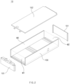
- FIG. 2 is an exploded view of the battery module case 10 according to an embodiment of the present invention.
- the battery module case 10 may include a main body 100, an end plate 101, and a cover plate 102.
- the main body 100 may be a frame that serves as reference for manufacture of the battery module case 10.
- the main body 100 is a frame having a shape having one side opened, and may be a frame that defines the accommodating space and is assembled with the end plate 101 and the cover plate 102, which will be described later.
- the main body 100 may have a longitudinal direction, and include a rectangular parallelepiped structure in which the front surface M1 and the rear surface M2 are opened in the longitudinal direction.
- the main body 100 may include a structure in which one surface M3 parallel to the longitudinal direction is opened. According to such a structure, the main body 100 may have a shape in which three surfaces of a rectangular parallelepiped shape are opened.
- FIG. 3 is a perspective view of the main body 100 according to an embodiment of the present invention.
- the main body 100 may include a bottom plate 1000 and a side plate 1001.
- the bottom plate 1000 may constitute a bottom surface of the main body 100.
- the side plate 1001 may be connected to each of both lateral portions of the bottom plate 1000.
- a pair of side plates 1001 may be connected to both the lateral portions of the bottom plate 1000, respectively, in a longitudinal direction of the bottom plate 1000.
- the side plate 1001 may be perpendicularly connected to the bottom plate 1000.
- the front surface M1 and the rear surface M2, each of which is defined by one side of the bottom plate 1000 and one side of each of the pair of side plates 1001, may be provided.
- the bottom plate 1000 may have a portion stepped.
- the bottom plate 1000 may include a body portion 1000a and a stepped portion 1000b.
- the body portion 1000a may be disposed at a central portion of the bottom plate 1000, and have a plate shape having a uniform thickness.
- the stepped portion 1000b is a portion connected to each of both ends of the body portion 1000a, and may have a stepped shape.
- the stepped portions 1000b may be connected not to both ends of the body portion 1000a, which are connected to the side plates 1001, but to both ends of the body portion 1000a, which are connected to the end plates 101, respectively.
- the stepped portions 1000b may be connected to both ends of the body portion 1000a, which constitute the front surface M1 and the rear surface M2 described above, respectively. That is, each of the front surface M1 and the rear surface M2 may be provided through the stepped portion 1000b and the side plate 1001.
- the stepped portion 1000b may be provided to be stepped toward a center of the body portion 1000a on each of both sides of the body portion 1000a, based on when the side plate 1001 is viewed.
- the stepped portion 1000b may have a thickness that is greater than a thickness of the body portion 1000a. That is, the bottom plate 1000 may have a structure in which the stepped portion 1000b on each of both the sides of the body portion 1000a protrudes upward in a state in which the body portion 1000a is disposed at a center, based on when the side plate 1001 is viewed.
- the end plate 101 may be connected to the main body 100 to cover the front surface M1 and the rear surface M2 of the main body 100.
- the end plate 101 may be provided in a pair, and the pair of end plates 101 may be disposed at front and rear sides, respectively, of the main body 100 to be connected to the main body 100.
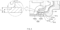
- FIG. 4 is a cross-sectional view of the battery module case, taken along line AA' in FIG. 1 .
- the end plate 101 may be coupled and connected to the stepped portion 1000b.
- the end plate 101 may include a coupling portion 1010 that is recessed to correspond to the shape of the stepped portion 1000b.
- the coupling portion 1010 may have a first surface 1010a, a second surface 1010b, and a third surface 1010c, based on when the side plate 1001 is viewed.
- a drain hole is defined in a central portion of the stepped portion 1000b, and a portion to be welded is provided at each of both sides of the drain hole in the stepped portion 1000b.
- a welding portion at one side has a length of 85 mm. In the experiments, when the welding portion at the one side is welded, a length of a welding defect occurring according to a thickness L 1 of the stepped portion 1000b is measured.
- the thickness L 1 of the stepped portion 1000b when the thickness L 1 of the stepped portion 1000b is 1.1 mm or greater, it may be confirmed that the welding defect length noticeably decreases. Accordingly, the thickness L 1 of the stepped portion 1000b may be 1.1 mm or greater. Preferably, the thickness L 1 of the stepped portion 1000b may be 1.2 mm or greater. When the thickness L 1 of the stepped portion 1000b is 1.2 mm or greater, it may be confirmed that the welding defect length remarkably decreases.
- the thickness L 1 of the stepped portion 1000b may be 1.5 mm or less.
- a sum of the thickness of the stepped portion 1000b and the thickness of the end plate 101 may be 3 mm, based on a cross section viewed in FIG. 4 . In other words, as the thickness of the stepped portion 1000b increases, the thickness of the end plate 101 may decrease.
- the thickness L1 of the stepped portion 1000b When the thickness L1 of the stepped portion 1000b is greater than 1.5 mm, the thickness of the end plate 101 may decrease to cause a problem that weld bondability is rather reduced due to fusing and welding by introduction from the stepped portion 1000b into the end plate 101. That is, in order to secure a weld depth, the thickness L 1 of the stepped portion 1000b may not be greater than the thickness of the end plate 101.
- the thickness L 1 of the stepped portion 1000b of the bottom plate 1000 is designed to be 1.2 mm to 1.5 mm, the weldability between the bottom plate 1000 and the end plate 101 may be greatly improved.
- the cover plate 102 may be connected to the main body 100 to cover the one surface M3 of the main body 100, which is parallel to the longitudinal direction of the bottom plate 1000.
- the one surface M3 may mean a top surface M3.
- the cover plate 102 may be connected to the main body 100 to cover the opened top surface M3 of the main body 100.
- the battery module according to an embodiment of the present invention may include a cell assembly structure accommodated inside the battery module case 10 to store electric energy and output the stored electric energy to the outside through a connecting terminal.
- an electrode cell which is injected with an electrolyte and activated in a state of including an electrode assembly therein, may be provided in a plurality to manufacture the cell assembly. That is, the cell assembly may be an assembly of a plurality of batteries.
- the battery module case 10 may accommodate such a cell assembly therein and be welded to block interaction between the cell assembly and an external space, so that the cell assembly is protected from an external factor such as an impact and heat.
- the battery module case 10 may include a main body 100, an end plate 101, and a cover plate 102.
- the main body 100 may include a bottom plate 1000 and a side plate 1001
- the bottom plate 1000 may include a body portion 1000a and a stepped portion 1000b.
- a thickness of the stepped portion 1000b may be adjusted to decrease a welding defect length between the main body 100 and the end plate 101 so that bonding force between the main body 100 and the end plate 101 increases. Consequently, the likelihood of breakage of the battery module may decrease, and the yield of the battery module may increase in the process for manufacturing the battery module.
Landscapes
- Chemical & Material Sciences (AREA)
- Chemical Kinetics & Catalysis (AREA)
- Electrochemistry (AREA)
- General Chemical & Material Sciences (AREA)
- Battery Mounting, Suspending (AREA)
- Sealing Battery Cases Or Jackets (AREA)
Abstract
Description
- The present application claims the benefit of the priority of
Korean Patent Application Nos. 10-2022-0065689, filed on May 27, 2022 10-2023-0062507, filed on May 15, 2023 - The present invention relates to a battery module case and a battery module including the same.
- In general, types of secondary batteries include nickel-cadmium batteries, nickel-hydrogen batteries, lithium-ion batteries, lithium-ion polymer batteries, and the like. These secondary batteries are applied to and used in not only small-sized products such as digital camera, P-DVD, MP3P, mobile phone, PDA, portable game device, power tool and E-bike, but also large-sized products such as electric vehicle and hybrid vehicle, which require high output, energy storage systems for storing surplus generated electricity or new renewable energy, and energy storage systems for backup.
- In order to manufacture these secondary batteries, a positive electrode current collector and a negative electrode current collector are coated with electrode active material slurry to make a positive electrode and a negative electrode, and then the positive electrode and the negative electrode are stacked at both sides of a separator to provide an electrode assembly having a predetermined shape. Thereafter, a battery case accommodates the electrode assembly and is sealed after injection of an electrolyte.
- As above, the battery case accommodates the electrode assembly and is injected with the electrolyte to manufacture a battery cell. A plurality of battery cells are accommodated in a frame-shaped case to be protected from an external impact, heat, vibration, and the like, in a state of being coupled to each other. Accordingly, a battery module may be manufactured, and then a control component such as a battery management system (BMS) may be provided in the battery module to complete a battery pack.
- During the processes of accommodating the battery cells in a battery module case and welding the battery module case, there is a problem that a welding defect occurs to reduce the yield of the battery module. Thus, there is a need for the battery module case having a structure that is capable of easily performing welding on the battery module case and increasing bonding force of the welding.
- An object of the present invention for solving the above problems is to provide a battery module case that improves a welding defect.
- A battery module case according to an embodiment of the present invention may include: a main body including a bottom plate, and a pair of side plates connected to both lateral portions of the bottom plate, respectively; an end plate that covers each of a front surface and a rear surface of the main body, which are disposed at front and rear sides, respectively, in a longitudinal direction of the bottom plate, to be connected to the main body; and a cover plate that covers one surface of the main body, which is parallel to the longitudinal direction of the bottom plate, to be connected to the main body, wherein one side of the bottom plate, which is connected to the end plate, is provided to be stepped.
- The bottom plate may include a body portion, and a stepped portion provided to be stepped on each of both ends of the body portion.
- The end plate may be coupled and connected to the stepped portion.
- The end plate may include a coupling portion that is recessed to correspond to a shape of the stepped portion.
- The coupling portion may have a first surface, which is connected to a bottom surface of the end plate and perpendicular to the bottom surface, and a second surface, which is connected to the first surface and perpendicular to the first surface, based on when the side plate is viewed, wherein the stepped portion is coupled to each of the first surface and the second surface so that the end plate and the main body are coupled to each other.
- The stepped portion may be provided to be stepped toward a center of the body portion on each of both sides of the body portion, based on when the side plate is viewed, and each of the front surface and the rear surface may be provided through the stepped portion and the side plate.
- The stepped portion may have a thickness that is greater than a thickness of the body portion.
- The thickness of the stepped portion may be 1.2 mm or greater.
- According to the preferred embodiments of the present invention, the welding defect may be improved to increase the bonding force between the components of the case and increase the yield of the battery module.
- In addition, the effects may be included which could be easily predicted by those skilled in the art from the configurations according to the preferred embodiments of the present invention.
- The following drawings attached in this specification illustrate a preferred embodiment of the present invention and function to make further understood the technical spirit of the present invention along with the detailed description of the invention. The present invention should not be construed as being limited to only the drawings.
-
FIG. 1 is a perspective view of a battery module case according to an embodiment of the present invention. -
FIG. 2 is an exploded view of a battery module case according to an embodiment of the present invention. -
FIG. 3 is a perspective view of a main body according to an embodiment of the present invention. -
FIG. 4 is a cross-sectional view of the battery module case, taken along line AA' inFIG. 1 . - Hereinafter, preferred embodiments of the present invention will be described in detail with reference to the accompanying drawings to enable those skilled in the art to which the present invention pertains to easily carry out the present invention. The present invention may, however, be embodied in different forms and should not be construed as limited by the embodiments set forth herein.
- The parts unrelated to the description, or the detailed descriptions of related well-known art that may unnecessarily obscure subject matters of the present invention, will be ruled out in order to clearly describe the present invention. Like reference numerals refer to like elements throughout the whole specification.
- Moreover, terms or words used in this specification and claims should not be restrictively interpreted as ordinary meanings or dictionary-based meanings, but should be interpreted as meanings and concepts conforming to the scope of the present invention on the basis of the principle that an inventor can properly define the concept of a term to describe and explain his or her invention in the best ways.
-
FIG. 1 is a perspective view of abattery module case 10 according to an embodiment of the present invention. - Referring to
FIG. 1 , thebattery module case 10 may have an accommodating space defined therein to accommodate a cell assembly to be described later. Thebattery module case 10 may accommodate the cell assembly to protect the cell assembly from an external environment such as an external impact and heat. In addition, thebattery module case 10 may be manufactured by accommodating the cell assembly therein in a state, in which one surface thereof is opened, and assembling and welding an opened portion. For example, in a rectangular parallelepiped frame having a front surface M1 and a rear surface M2 that are opened, the front surface M1 and the rear surface M2 may be covered and welded to manufacture thebattery module case 10. During the welding of thebattery module case 10, thebattery module case 10 may be more stably welded through a structure in which a portion of thebattery module case 10 is stepped. Specifically, a thickness of each of portions to be welded may be adjusted so that bonding force between components of thebattery module case 10 further increases. -
FIG. 2 is an exploded view of thebattery module case 10 according to an embodiment of the present invention. - Referring to
FIG. 2 , thebattery module case 10 may include amain body 100, anend plate 101, and acover plate 102. - The
main body 100 may be a frame that serves as reference for manufacture of thebattery module case 10. In other words, themain body 100 is a frame having a shape having one side opened, and may be a frame that defines the accommodating space and is assembled with theend plate 101 and thecover plate 102, which will be described later. Specifically, themain body 100 may have a longitudinal direction, and include a rectangular parallelepiped structure in which the front surface M1 and the rear surface M2 are opened in the longitudinal direction. In addition, themain body 100 may include a structure in which one surface M3 parallel to the longitudinal direction is opened. According to such a structure, themain body 100 may have a shape in which three surfaces of a rectangular parallelepiped shape are opened. -
FIG. 3 is a perspective view of themain body 100 according to an embodiment of the present invention. - Referring to
FIG. 3 , themain body 100 may include abottom plate 1000 and aside plate 1001. For example, thebottom plate 1000 may constitute a bottom surface of themain body 100. In a state in which thebottom plate 1000 constitutes the bottom surface of themain body 100, theside plate 1001 may be connected to each of both lateral portions of thebottom plate 1000. In other words, a pair ofside plates 1001 may be connected to both the lateral portions of thebottom plate 1000, respectively, in a longitudinal direction of thebottom plate 1000. In this case, theside plate 1001 may be perpendicularly connected to thebottom plate 1000. As a result, the front surface M1 and the rear surface M2, each of which is defined by one side of thebottom plate 1000 and one side of each of the pair ofside plates 1001, may be provided. - The
bottom plate 1000 may have a portion stepped. For example, thebottom plate 1000 may include abody portion 1000a and astepped portion 1000b. Thebody portion 1000a may be disposed at a central portion of thebottom plate 1000, and have a plate shape having a uniform thickness. Thestepped portion 1000b is a portion connected to each of both ends of thebody portion 1000a, and may have a stepped shape. Specifically, the steppedportions 1000b may be connected not to both ends of thebody portion 1000a, which are connected to theside plates 1001, but to both ends of thebody portion 1000a, which are connected to theend plates 101, respectively. In other words, the steppedportions 1000b may be connected to both ends of thebody portion 1000a, which constitute the front surface M1 and the rear surface M2 described above, respectively. That is, each of the front surface M1 and the rear surface M2 may be provided through the steppedportion 1000b and theside plate 1001. - More specifically, the stepped
portion 1000b may be provided to be stepped toward a center of thebody portion 1000a on each of both sides of thebody portion 1000a, based on when theside plate 1001 is viewed. In addition, the steppedportion 1000b may have a thickness that is greater than a thickness of thebody portion 1000a. That is, thebottom plate 1000 may have a structure in which the steppedportion 1000b on each of both the sides of thebody portion 1000a protrudes upward in a state in which thebody portion 1000a is disposed at a center, based on when theside plate 1001 is viewed. - The
end plate 101 may be connected to themain body 100 to cover the front surface M1 and the rear surface M2 of themain body 100. In other words, theend plate 101 may be provided in a pair, and the pair ofend plates 101 may be disposed at front and rear sides, respectively, of themain body 100 to be connected to themain body 100. -
FIG. 4 is a cross-sectional view of the battery module case, taken along line AA' inFIG. 1 . - Referring to
FIG. 4 , theend plate 101 may be coupled and connected to the steppedportion 1000b. Specifically, theend plate 101 may include acoupling portion 1010 that is recessed to correspond to the shape of the steppedportion 1000b. For example, thecoupling portion 1010 may have afirst surface 1010a, asecond surface 1010b, and athird surface 1010c, based on when theside plate 1001 is viewed. - The
first surface 1010a may be connected to abottom surface 101a of theend plate 101 and perpendicular to thebottom surface 101a. In addition, thesecond surface 1010b may be connected to thefirst surface 1010a and perpendicular to thefirst surface 1010a. Lastly, thethird surface 1010c may be connected to thesecond surface 1010b and perpendicular to thesecond surface 1010b. In this case, in a state in which an extension line of thebottom surface 101a of theend plate 101 matches an extension line of a bottom surface of the steppedportion 1000b, the steppedportion 1000b may be inserted toward thefirst surface 1010a to be coupled and welded to each of thefirst surface 1010a and thesecond surface 1010b so that theend plate 101 and themain body 100 are coupled to each other. - Hereinafter, the contents and results of experiments for measuring weldability between the
main body 100 and theend plate 101 will be described. Specifically, during the welding of the steppedportion 1000b to theend plate 101, a length of an occurring welding defect is measured. - More specifically, a drain hole is defined in a central portion of the stepped
portion 1000b, and a portion to be welded is provided at each of both sides of the drain hole in the steppedportion 1000b. In this case, a welding portion at one side has a length of 85 mm. In the experiments, when the welding portion at the one side is welded, a length of a welding defect occurring according to a thickness L1 of the steppedportion 1000b is measured. - The results of measuring the length of the welding defect occurring according to the thickness L1 of the stepped
portion 1000b are shown in Table 1 below.[Table 1] L1 Welding defect length 1.2 mm 0.78 mm 1.1 mm 3.45 mm 0.9 mm 15.98 mm - Referring to Table 1, when the thickness L1 of the stepped
portion 1000b is 1.1 mm or greater, it may be confirmed that the welding defect length noticeably decreases. Accordingly, the thickness L1 of the steppedportion 1000b may be 1.1 mm or greater. Preferably, the thickness L1 of the steppedportion 1000b may be 1.2 mm or greater. When the thickness L1 of the steppedportion 1000b is 1.2 mm or greater, it may be confirmed that the welding defect length remarkably decreases. - In addition, considering a thickness of a bonded portion of the
end plate 101, the thickness L1 of the steppedportion 1000b may be 1.5 mm or less. A sum of the thickness of the steppedportion 1000b and the thickness of theend plate 101 may be 3 mm, based on a cross section viewed inFIG. 4 . In other words, as the thickness of the steppedportion 1000b increases, the thickness of theend plate 101 may decrease. - When the thickness L1 of the stepped
portion 1000b is greater than 1.5 mm, the thickness of theend plate 101 may decrease to cause a problem that weld bondability is rather reduced due to fusing and welding by introduction from the steppedportion 1000b into theend plate 101. That is, in order to secure a weld depth, the thickness L1 of the steppedportion 1000b may not be greater than the thickness of theend plate 101. - As a result, when the thickness L1 of the stepped
portion 1000b of thebottom plate 1000 according to an embodiment of the present invention is designed to be 1.2 mm to 1.5 mm, the weldability between thebottom plate 1000 and theend plate 101 may be greatly improved. - As above, as the thickness of the stepped
portion 1000b is adjusted with respect to thebody portion 1000a, themain body 100 and theend plate 101 may be welded to each other by higher binding force, and due the higher binding force, thebattery module case 10 may be prevented from being broken so that the yield of the battery module greatly increases. - The
cover plate 102 may be connected to themain body 100 to cover the one surface M3 of themain body 100, which is parallel to the longitudinal direction of thebottom plate 1000. For example, the one surface M3 may mean a top surface M3. In this case, thecover plate 102 may be connected to themain body 100 to cover the opened top surface M3 of themain body 100. - Hereinafter, a battery module manufactured using the
battery module case 10 described above will be described. In the battery module according to an embodiment of the present invention, contents duplicated with the contents about thebattery module case 10 described above will be omitted. - The battery module according to an embodiment of the present invention may include a cell assembly structure accommodated inside the
battery module case 10 to store electric energy and output the stored electric energy to the outside through a connecting terminal. - For example, an electrode cell, which is injected with an electrolyte and activated in a state of including an electrode assembly therein, may be provided in a plurality to manufacture the cell assembly. That is, the cell assembly may be an assembly of a plurality of batteries.
- The
battery module case 10 may accommodate such a cell assembly therein and be welded to block interaction between the cell assembly and an external space, so that the cell assembly is protected from an external factor such as an impact and heat. - Specifically, the
battery module case 10 may include amain body 100, anend plate 101, and acover plate 102. In addition, themain body 100 may include abottom plate 1000 and aside plate 1001, and thebottom plate 1000 may include abody portion 1000a and a steppedportion 1000b. - As above, a thickness of the stepped
portion 1000b may be adjusted to decrease a welding defect length between themain body 100 and theend plate 101 so that bonding force between themain body 100 and theend plate 101 increases. Consequently, the likelihood of breakage of the battery module may decrease, and the yield of the battery module may increase in the process for manufacturing the battery module. - The description of the present invention is intended to be illustrative, and various changes and modifications can be made by those of ordinary skill in the art to which the present invention pertains, without departing from the spirit and scope of the present invention as defined by the appended claims.
- Therefore, the embodiments set forth herein are to describe the technical spirit of the present invention and not to limit. The scope of the technical spirit of the present invention is not limited by the embodiments.
- Moreover, the protective scope of the present invention should be determined by reasonable interpretation of the appended claims and all technical concepts coming within the equivalency range of the present application should be interpreted to be in the scope of the right of the present application.
- [Description of the Symbols]
- 10: Battery module case
- 100: Main body
- 101: End plate
- 102: Cover plate
- 1000: Bottom plate
- 1001: Side plate
- 1000a: Body portion
- 1000b: Stepped portion
- 1010: Coupling portion
- 1010a: First surface
- 1010b: Second surface
- 1010c: Third surface
- 101a: Bottom surface of end plate
- M1: Front surface
- M2: Rear surface
- M3: One surface
- L1: Thickness of stepped portion
- L2: Thickness of body portion
Claims (9)
- A battery module case comprising:a main body comprising a bottom plate, and a pair of side plates connected to both lateral portions of the bottom plate, respectively;an end plate configured to cover each of a front surface and a rear surface of the main body, which are disposed at front and rear sides, respectively, in a longitudinal direction of the bottom plate, to be connected to the main body; anda cover plate configured to cover one surface of the main body, which is parallel to the longitudinal direction of the bottom plate, to be connected to the main body,wherein one side of the bottom plate, which is connected to the end plate, is provided to be stepped.
- The battery module case of claim 1, wherein the bottom plate comprises:a body portion; anda stepped portion provided to be stepped on each of both ends of the body portion.
- The battery module case of claim 2, wherein the end plate is coupled and connected to the stepped portion.
- The battery module case of claim 3, wherein the end plate comprises a coupling portion that is recessed to correspond to a shape of the stepped portion.
- The battery module case of claim 4, wherein the coupling portion has a first surface, which is connected to a bottom surface of the end plate and perpendicular to the bottom surface, and a second surface, which is connected to the first surface and perpendicular to the first surface, based on when the side plate is viewed,
wherein the stepped portion is coupled to each of the first surface and the second surface so that the end plate and the main body are coupled to each other. - The battery module case of claim 2, wherein the stepped portion is provided to be stepped toward a center of the body portion on each of both sides of the body portion, based on when the side plate is viewed, and
each of the front surface and the rear surface is provided through the stepped portion and the side plate. - The battery module case of claim 6, wherein the stepped portion has a thickness that is greater than a thickness of the body portion.
- The battery module case of claim 7, wherein the thickness of the stepped portion is 1.2 mm or greater.
- A battery module comprising:the battery module case of claim 1; anda cell assembly accommodated inside the battery module case.
Applications Claiming Priority (3)
| Application Number | Priority Date | Filing Date | Title |
|---|---|---|---|
| KR20220065689 | 2022-05-27 | ||
| KR1020230062507A KR20230165702A (en) | 2022-05-27 | 2023-05-15 | Battery module case and battery module comprising the same |
| PCT/KR2023/007010 WO2023229347A1 (en) | 2022-05-27 | 2023-05-23 | Battery module case and battery module comprising same |
Publications (2)
| Publication Number | Publication Date |
|---|---|
| EP4513642A1 true EP4513642A1 (en) | 2025-02-26 |
| EP4513642A4 EP4513642A4 (en) | 2025-12-17 |
Family
ID=88919697
Family Applications (1)
| Application Number | Title | Priority Date | Filing Date |
|---|---|---|---|
| EP23812121.4A Pending EP4513642A4 (en) | 2022-05-27 | 2023-05-23 | BATTERY MODULE HOUSING AND BATTERY MODULE INCLUDING IT |
Country Status (5)
| Country | Link |
|---|---|
| US (1) | US20250343309A1 (en) |
| EP (1) | EP4513642A4 (en) |
| JP (1) | JP2025517507A (en) |
| CN (1) | CN119213612A (en) |
| WO (1) | WO2023229347A1 (en) |
Family Cites Families (12)
| Publication number | Priority date | Publication date | Assignee | Title |
|---|---|---|---|---|
| JP2013084444A (en) * | 2011-10-08 | 2013-05-09 | Sanyo Electric Co Ltd | Electric power supply apparatus and vehicle including the same |
| US20140295235A1 (en) * | 2013-03-29 | 2014-10-02 | Samsung Sdi Co., Ltd. | Battery module |
| KR20160137715A (en) | 2015-05-20 | 2016-12-01 | 엘지디스플레이 주식회사 | Organic light emitting display device and fabricating method thereof |
| WO2018106026A1 (en) * | 2016-12-06 | 2018-06-14 | 에스케이이노베이션 주식회사 | Secondary battery module |
| CN207818701U (en) * | 2018-01-31 | 2018-09-04 | 宁德时代新能源科技股份有限公司 | battery module |
| CN113508490B (en) * | 2019-02-27 | 2023-06-23 | 本田技研工业株式会社 | Fixing structure of end plate and battery device |
| KR102473335B1 (en) * | 2019-06-12 | 2022-12-01 | 주식회사 엘지에너지솔루션 | Battery module and battery pack including the same |
| KR102472690B1 (en) * | 2019-07-19 | 2022-11-29 | 주식회사 엘지에너지솔루션 | Battery module and battery pack including the same |
| KR102473336B1 (en) * | 2019-10-07 | 2022-12-01 | 주식회사 엘지에너지솔루션 | Battery module and battery pack including the same |
| KR102398574B1 (en) * | 2019-10-10 | 2022-05-13 | 주식회사 엘지에너지솔루션 | Battery module and battery pack including the same |
| KR102767701B1 (en) * | 2020-03-06 | 2025-02-12 | 주식회사 엘지에너지솔루션 | Battery module and manufacturing method thereof |
| CN114496886A (en) | 2020-11-13 | 2022-05-13 | 新光电气工业株式会社 | Substrate fixing device, electrostatic chuck and manufacturing method of electrostatic chuck |
-
2023
- 2023-05-23 CN CN202380041186.2A patent/CN119213612A/en active Pending
- 2023-05-23 US US18/867,723 patent/US20250343309A1/en active Pending
- 2023-05-23 JP JP2024569474A patent/JP2025517507A/en active Pending
- 2023-05-23 WO PCT/KR2023/007010 patent/WO2023229347A1/en not_active Ceased
- 2023-05-23 EP EP23812121.4A patent/EP4513642A4/en active Pending
Also Published As
| Publication number | Publication date |
|---|---|
| US20250343309A1 (en) | 2025-11-06 |
| JP2025517507A (en) | 2025-06-05 |
| CN119213612A (en) | 2024-12-27 |
| EP4513642A4 (en) | 2025-12-17 |
| WO2023229347A1 (en) | 2023-11-30 |
Similar Documents
| Publication | Publication Date | Title |
|---|---|---|
| JP7047220B2 (en) | Battery module including rechargeable battery and bus bar | |
| EP3644401B1 (en) | Battery module, and battery pack and vehicle comprising same | |
| US20240170790A1 (en) | Battery module and battery pack including the same | |
| EP3926734B1 (en) | Battery module and battery pack including the esame | |
| US11456502B2 (en) | Battery module, battery pack comprising same battery module, and vehicle comprising same battery pack | |
| KR102690217B1 (en) | Angular battery | |
| KR102890100B1 (en) | Batteries, devices, methods and facilities for manufacturing batteries | |
| JP2022523953A (en) | Battery module and battery pack containing it | |
| US12368202B2 (en) | Battery module, battery pack comprising battery module and vehicle | |
| KR20160119509A (en) | Battery Cell containing Protection Circuit Member and Method of Manufacturing the Same | |
| US20230031678A1 (en) | Battery Module, and Battery Pack and Vehicle Comprising Battery Module | |
| KR102834168B1 (en) | Battery Cell Assembly With Increased Shock Resistance, And Manufacturing Method Thereof | |
| US20250343309A1 (en) | Battery Module Case And Battery Module Including The Same | |
| US12456775B2 (en) | Battery pack and vehicle including the same | |
| EP4379923B1 (en) | Battery module, battery pack, vehicle, and method for manufacturing battery module | |
| KR101658587B1 (en) | Lithium Secondary Battery and Battery Pack Comprising The Same | |
| US20250030099A1 (en) | Logical Cell, Secondary Battery Module and Secondary Pack Including the Same | |
| JP2025537977A (en) | Battery pack and manufacturing method thereof | |
| US12476331B2 (en) | Battery module and battery pack including the same | |
| KR20230165702A (en) | Battery module case and battery module comprising the same | |
| KR102925167B1 (en) | Battery module and battery pack including the same and vehicle including the same | |
| KR20160054268A (en) | Secondary battery cell and battery module including the same | |
| US20260005353A1 (en) | Battery module and method for manufacturing the battery module | |
| KR20200092672A (en) | Secondary battery and a secondary battery module including the same | |
| EP4708508A1 (en) | Battery pack and vehicle including same |
Legal Events
| Date | Code | Title | Description |
|---|---|---|---|
| STAA | Information on the status of an ep patent application or granted ep patent |
Free format text: STATUS: THE INTERNATIONAL PUBLICATION HAS BEEN MADE |
|
| PUAI | Public reference made under article 153(3) epc to a published international application that has entered the european phase |
Free format text: ORIGINAL CODE: 0009012 |
|
| STAA | Information on the status of an ep patent application or granted ep patent |
Free format text: STATUS: REQUEST FOR EXAMINATION WAS MADE |
|
| 17P | Request for examination filed |
Effective date: 20241120 |
|
| AK | Designated contracting states |
Kind code of ref document: A1 Designated state(s): AL AT BE BG CH CY CZ DE DK EE ES FI FR GB GR HR HU IE IS IT LI LT LU LV MC ME MK MT NL NO PL PT RO RS SE SI SK SM TR |
|
| DAV | Request for validation of the european patent (deleted) | ||
| DAX | Request for extension of the european patent (deleted) | ||
| REG | Reference to a national code |
Ref country code: DE Ref legal event code: R079 Free format text: PREVIOUS MAIN CLASS: H01M0050200000 Ipc: H01M0050209000 |
|
| A4 | Supplementary search report drawn up and despatched |
Effective date: 20251119 |
|
| RIC1 | Information provided on ipc code assigned before grant |
Ipc: H01M 50/209 20210101AFI20251113BHEP Ipc: H01M 50/271 20210101ALI20251113BHEP Ipc: H01M 50/244 20210101ALI20251113BHEP Ipc: H01M 50/262 20210101ALI20251113BHEP Ipc: H01M 50/269 20210101ALI20251113BHEP |
|
| STAA | Information on the status of an ep patent application or granted ep patent |
Free format text: STATUS: EXAMINATION IS IN PROGRESS |