EP4513641A1 - Top cover assembly and battery - Google Patents
Top cover assembly and battery Download PDFInfo
- Publication number
- EP4513641A1 EP4513641A1 EP23866831.3A EP23866831A EP4513641A1 EP 4513641 A1 EP4513641 A1 EP 4513641A1 EP 23866831 A EP23866831 A EP 23866831A EP 4513641 A1 EP4513641 A1 EP 4513641A1
- Authority
- EP
- European Patent Office
- Prior art keywords
- top cover
- cover sheet
- boss
- cover assembly
- hole
- Prior art date
- Legal status (The legal status is an assumption and is not a legal conclusion. Google has not performed a legal analysis and makes no representation as to the accuracy of the status listed.)
- Pending
Links
Images


Classifications
-
- H—ELECTRICITY
- H01—ELECTRIC ELEMENTS
- H01M—PROCESSES OR MEANS, e.g. BATTERIES, FOR THE DIRECT CONVERSION OF CHEMICAL ENERGY INTO ELECTRICAL ENERGY
- H01M50/00—Constructional details or processes of manufacture of the non-active parts of electrochemical cells other than fuel cells, e.g. hybrid cells
- H01M50/10—Primary casings; Jackets or wrappings
- H01M50/147—Lids or covers
- H01M50/148—Lids or covers characterised by their shape
- H01M50/15—Lids or covers characterised by their shape for prismatic or rectangular cells
-
- H—ELECTRICITY
- H01—ELECTRIC ELEMENTS
- H01M—PROCESSES OR MEANS, e.g. BATTERIES, FOR THE DIRECT CONVERSION OF CHEMICAL ENERGY INTO ELECTRICAL ENERGY
- H01M50/00—Constructional details or processes of manufacture of the non-active parts of electrochemical cells other than fuel cells, e.g. hybrid cells
- H01M50/10—Primary casings; Jackets or wrappings
- H01M50/147—Lids or covers
- H01M50/166—Lids or covers characterised by the methods of assembling casings with lids
- H01M50/169—Lids or covers characterised by the methods of assembling casings with lids by welding, brazing or soldering
-
- H—ELECTRICITY
- H01—ELECTRIC ELEMENTS
- H01M—PROCESSES OR MEANS, e.g. BATTERIES, FOR THE DIRECT CONVERSION OF CHEMICAL ENERGY INTO ELECTRICAL ENERGY
- H01M50/00—Constructional details or processes of manufacture of the non-active parts of electrochemical cells other than fuel cells, e.g. hybrid cells
- H01M50/10—Primary casings; Jackets or wrappings
- H01M50/172—Arrangements of electric connectors penetrating the casing
- H01M50/174—Arrangements of electric connectors penetrating the casing adapted for the shape of the cells
- H01M50/176—Arrangements of electric connectors penetrating the casing adapted for the shape of the cells for prismatic or rectangular cells
-
- H—ELECTRICITY
- H01—ELECTRIC ELEMENTS
- H01M—PROCESSES OR MEANS, e.g. BATTERIES, FOR THE DIRECT CONVERSION OF CHEMICAL ENERGY INTO ELECTRICAL ENERGY
- H01M50/00—Constructional details or processes of manufacture of the non-active parts of electrochemical cells other than fuel cells, e.g. hybrid cells
- H01M50/10—Primary casings; Jackets or wrappings
- H01M50/183—Sealing members
- H01M50/184—Sealing members characterised by their shape or structure
-
- H—ELECTRICITY
- H01—ELECTRIC ELEMENTS
- H01M—PROCESSES OR MEANS, e.g. BATTERIES, FOR THE DIRECT CONVERSION OF CHEMICAL ENERGY INTO ELECTRICAL ENERGY
- H01M50/00—Constructional details or processes of manufacture of the non-active parts of electrochemical cells other than fuel cells, e.g. hybrid cells
- H01M50/10—Primary casings; Jackets or wrappings
- H01M50/183—Sealing members
- H01M50/186—Sealing members characterised by the disposition of the sealing members
- H01M50/188—Sealing members characterised by the disposition of the sealing members the sealing members being arranged between the lid and terminal
-
- H—ELECTRICITY
- H01—ELECTRIC ELEMENTS
- H01M—PROCESSES OR MEANS, e.g. BATTERIES, FOR THE DIRECT CONVERSION OF CHEMICAL ENERGY INTO ELECTRICAL ENERGY
- H01M50/00—Constructional details or processes of manufacture of the non-active parts of electrochemical cells other than fuel cells, e.g. hybrid cells
- H01M50/50—Current conducting connections for cells or batteries
- H01M50/543—Terminals
- H01M50/564—Terminals characterised by their manufacturing process
- H01M50/566—Terminals characterised by their manufacturing process by welding, soldering or brazing
-
- H—ELECTRICITY
- H01—ELECTRIC ELEMENTS
- H01M—PROCESSES OR MEANS, e.g. BATTERIES, FOR THE DIRECT CONVERSION OF CHEMICAL ENERGY INTO ELECTRICAL ENERGY
- H01M50/00—Constructional details or processes of manufacture of the non-active parts of electrochemical cells other than fuel cells, e.g. hybrid cells
- H01M50/50—Current conducting connections for cells or batteries
- H01M50/572—Means for preventing undesired use or discharge
- H01M50/584—Means for preventing undesired use or discharge for preventing incorrect connections inside or outside the batteries
- H01M50/59—Means for preventing undesired use or discharge for preventing incorrect connections inside or outside the batteries characterised by the protection means
- H01M50/593—Spacers; Insulating plates
-
- Y—GENERAL TAGGING OF NEW TECHNOLOGICAL DEVELOPMENTS; GENERAL TAGGING OF CROSS-SECTIONAL TECHNOLOGIES SPANNING OVER SEVERAL SECTIONS OF THE IPC; TECHNICAL SUBJECTS COVERED BY FORMER USPC CROSS-REFERENCE ART COLLECTIONS [XRACs] AND DIGESTS
- Y02—TECHNOLOGIES OR APPLICATIONS FOR MITIGATION OR ADAPTATION AGAINST CLIMATE CHANGE
- Y02E—REDUCTION OF GREENHOUSE GAS [GHG] EMISSIONS, RELATED TO ENERGY GENERATION, TRANSMISSION OR DISTRIBUTION
- Y02E60/00—Enabling technologies; Technologies with a potential or indirect contribution to GHG emissions mitigation
- Y02E60/10—Energy storage using batteries
Definitions
- the present application relates to the technical field of batteries, for example, to a top cover assembly and a battery.
- the top covers of the power batteries are mainly used in new energy vehicles.
- the top cover of the battery is mainly manufactured by an injection molding process and a riveting process.
- the injection molding process is limited by the site of the injection molding equipment and by the material molding process, resulting in a lower production efficiency of the top cover and the inability to meet the growing battery cell market. Riveting process procedures are relatively numerous, complicated in structure, and cumbersome in production steps, which also results in a lower production efficiency of the top cover and cannot meet the growing battery cell market.
- the present application provides a top cover assembly and a battery, which may reduce production costs, improve assembly efficiency and use safety.
- an embodiment of the present application provides a top cover assembly including:
- a width of an opening of the welding recess is greater than a width of a bottom of the welding recess.
- the top cover assembly further includes: a sealing ring including a first sealing portion sleeved between an outer periphery of the boss and a wall of the mounting hole, and a second sealing portion disposed at a lower end of the first sealing portion and extended outwardly along a radial direction of the first sealing portion, in which the second sealing portion is sealingly abutted between a lower end face of the top cover sheet and an upper end face of the body.
- the top cover assembly further includes: a lower insulating plate provided at a lower end of the top cover sheet, in which the lower insulating plate includes a through hole, the boss passes through the through hole, the body is abutted against a lower end surface of the lower insulating plate, and the second sealing portion is provided between a wall of the through hole and the boss.
- the lower end of the top cover sheet includes a first mounting slot
- a side of the lower insulating plate which is adjacent to the top cover sheet includes a protrusion, and the protrusion is snapped in the first mounting slot.
- a side of the lower insulating plate which is away from the top cover sheet includes a second mounting slot, the second mounting slot is provided in correspondence with the protrusion, and the body is snapped in the second mounting slot.
- the top cover assembly further includes: an upper insulating plate, in which the upper end of the top cover sheet includes a third mounting slot, the upper insulating plate is snapped in the third mounting slot, a fixing recess is formed in the upper insulating plate, a limiting hole is formed at a bottom of the fixing recess, the connecting block is snapped in the fixing recess, and the boss penetrates through the limiting hole and is connected with the connecting hole in an insertion manner.
- the bottom of the fixing recess includes a positioning post
- a lower end of the connecting block includes a positioning recess
- the positioning post is snapped in the positioning recess.
- the a lower end of the pole is provided with a weight-reducing recess.
- embodiments of the present application provide a battery including the top cover assembly mentioned above.
- Embodiments of the present application provide a top cover assembly including a top cover sheet, a pole and a connecting block.
- the boss of each pole passes through the respective mounting hole.
- each connecting block is sleeved at the upper end of the respective boss and welded at the respective welding recess formed by the first notch and the second notch, so that the connecting block and the pole are fixed.
- the assembling operation of the top cover assembly is simple and quick, the connecting block and the pole are easily fixed, and the number of parts used is small, thereby improving the assembling efficiency and reducing the production cost.
- each connecting block of the top cover assembly has the function of fixing and preventing rotation of the respective pole, thereby improving the structural strength and the use safety of the top cover assembly.
Landscapes
- Chemical & Material Sciences (AREA)
- Chemical Kinetics & Catalysis (AREA)
- Electrochemistry (AREA)
- General Chemical & Material Sciences (AREA)
- Engineering & Computer Science (AREA)
- Manufacturing & Machinery (AREA)
- Connection Of Batteries Or Terminals (AREA)
Abstract
Description
- This application claims priority to
Chinese Patent Application No. 202211145248.8, filed September 20, 2022 - The present application relates to the technical field of batteries, for example, to a top cover assembly and a battery.
- The top covers of the power batteries are mainly used in new energy vehicles. In related art, the top cover of the battery is mainly manufactured by an injection molding process and a riveting process. The injection molding process is limited by the site of the injection molding equipment and by the material molding process, resulting in a lower production efficiency of the top cover and the inability to meet the growing battery cell market. Riveting process procedures are relatively numerous, complicated in structure, and cumbersome in production steps, which also results in a lower production efficiency of the top cover and cannot meet the growing battery cell market.
- The present application provides a top cover assembly and a battery, which may reduce production costs, improve assembly efficiency and use safety.
- In a first aspect, an embodiment of the present application provides a top cover assembly including:
- a top cover sheet including a mounting hole;
- a pole including a body and a boss provided on the body, in which the body is insulatively connected to a lower end of the top cover sheet, the boss is passed through the mounting hole and insulatively connected to the top cover sheet, and an outer peripheral edge of an upper end of the boss is provided with a first notch; and
- a connecting block insulatively connected to an upper end of the top cover sheet, in which the connecting block is provided with a connecting hole, the upper end of the boss is inserted into the connecting hole, an upper end of a wall of the connecting hole is provided with a second notch circumferentially, and the first notch and the second notch form a welding recess.
- In one embodiment, a width of an opening of the welding recess is greater than a width of a bottom of the welding recess.
- In one embodiment, the top cover assembly further includes:
a sealing ring including a first sealing portion sleeved between an outer periphery of the boss and a wall of the mounting hole, and a second sealing portion disposed at a lower end of the first sealing portion and extended outwardly along a radial direction of the first sealing portion, in which the second sealing portion is sealingly abutted between a lower end face of the top cover sheet and an upper end face of the body. - In one embodiment, the top cover assembly further includes:
a lower insulating plate provided at a lower end of the top cover sheet, in which the lower insulating plate includes a through hole, the boss passes through the through hole, the body is abutted against a lower end surface of the lower insulating plate, and the second sealing portion is provided between a wall of the through hole and the boss. - In one embodiment, the lower end of the top cover sheet includes a first mounting slot, and a side of the lower insulating plate which is adjacent to the top cover sheet includes a protrusion, and the protrusion is snapped in the first mounting slot.
- In one embodiment, a side of the lower insulating plate which is away from the top cover sheet includes a second mounting slot, the second mounting slot is provided in correspondence with the protrusion, and the body is snapped in the second mounting slot.
- In one embodiment, the top cover assembly further includes:
an upper insulating plate, in which the upper end of the top cover sheet includes a third mounting slot, the upper insulating plate is snapped in the third mounting slot, a fixing recess is formed in the upper insulating plate, a limiting hole is formed at a bottom of the fixing recess, the connecting block is snapped in the fixing recess, and the boss penetrates through the limiting hole and is connected with the connecting hole in an insertion manner. - In one embodiment, the bottom of the fixing recess includes a positioning post, a lower end of the connecting block includes a positioning recess, and the positioning post is snapped in the positioning recess.
- In one embodiment, the a lower end of the pole is provided with a weight-reducing recess.
- In a first aspect, embodiments of the present application provide a battery including the top cover assembly mentioned above.
- Beneficial effects of the present application are as follows.
- Embodiments of the present application provide a top cover assembly including a top cover sheet, a pole and a connecting block. When the top cover assembly is assembled, the boss of each pole passes through the respective mounting hole. Then, each connecting block is sleeved at the upper end of the respective boss and welded at the respective welding recess formed by the first notch and the second notch, so that the connecting block and the pole are fixed. The assembling operation of the top cover assembly is simple and quick, the connecting block and the pole are easily fixed, and the number of parts used is small, thereby improving the assembling efficiency and reducing the production cost. At the same time, each connecting block of the top cover assembly has the function of fixing and preventing rotation of the respective pole, thereby improving the structural strength and the use safety of the top cover assembly.
-
-
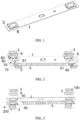
FIG. 1 is a schematic structural diagram of a top cover assembly according to embodiments of the present application; -
FIG. 2 is an exploded view of a top cover assembly at a first viewing angle according to embodiments of the present application; -
FIG. 3 is an exploded view of a top cover assembly at a second viewing angle according to embodiments of the present application; -
FIG. 4 is a cross-sectional view of a top cover assembly according to embodiments of the present application; -
FIG. 5 is an enlarged view at part A inFIG. 4 ; -
FIG. 6 is a schematic structural diagram of a pole according to embodiments of the present application; -
FIG. 7 is a schematic structural diagram of a connection block according to embodiments of the present application; and -
FIG. 8 is a schematic structural diagram of a sealing ring according to embodiments of the present application. - In the figure:
- 1. top cover sheet; 2. pole; 21. body; 22. boss; 3. connecting block; 4. sealing ring; 41. first sealing portion; 42. second sealing portion; 5. lower insulating plate; 51. protrusion; 6. upper insulating plate; 61. positioning post;
- 10. mounting hole; 20. welding recess; 201. first notch; 202. second notch; 30. connecting hole; 40. through hole; 50. first mounting slot; 60. second mounting slot; 70. third mounting slot; 80. fixing recess; 90. limiting hole; 100. positioning recess; and 200. weight-reducing recess.
- In the description of the present application, unless otherwise expressly specified and limited, the terms "conjoint", "connect", and "fix" are to be understood in a broad sense, for example, as a fixed connection, as a detachable connection, or as a one-piece connection; also as a mechanical connection or an electrical connection; or may be directly connected or indirectly connected by means of an intermediate medium; or may be internal communication of the two elements or interaction of the two elements. The specific meaning of the above terms in the present application may be understood by one of ordinary skill in the art as the case may be.
- For the purposes of this application, unless otherwise expressly specified and limited, that the first feature is "over" or "under" the second feature may include the first feature is in direct contact with the second feature, or may include the first feature is not in direct contact with the second feature, but by means of a separate feature therebetween. Furthermore, that the first feature is "on", "above" and "over" the second feature includes the first feature is directly above and diagonally above the second feature, or simply indicating that the first feature is horizontally higher than the second feature. That the first feature is "below", "under", and "beneath" the second feature includes the first feature is directly below and diagonally below the second feature, or simply indicating that the first feature is horizontally smaller than the second feature.
- In the description of this embodiment, the terms "upper", "lower", "right", and other orientation or positional relationships are based on the orientation or positional relationship shown in the accompanying drawings, and are only for convenience of description and simplified operation. It is not intended to indicate or imply that the device or the element referred to must have a specific orientation, be constructed and operated in a specific orientation, and therefore should not be construed as a limitation on the present application. In addition, the terms "first" and "second" are only used for descriptive purposes and have no special meaning.
- As shown in
FIGS. 1 to 8 , the present embodiment provides a top cover assembly including atop cover sheet 1, apole 2, and a connectingblock 3. Thepole 2 may be a positive pole or a negative pole. In the present embodiment, thepole 2 is used as the negative pole. In other embodiments, when thepole 2 is used as the positive pole, other structures are the same as when thepole 2 is used as the negative pole, and details are not described herein. - In one embodiment, as shown in
FIGS. 2 to 7 , thetop cover sheet 1 includes mountingholes 10. Thepole 2 includes abody 21 and aboss 22 provided on thebody 21. Thebody 21 is insulatively connected to a lower end of thetop cover sheet 1. Theboss 22 passes through the mountinghole 10 and is insulatively connected to thetop cover sheet 1. An outer peripheral edge of an upper end of theboss 22 is provided with afirst notch 201. The connectingblocks 3 are insulatively connected to an upper end of thetop cover sheet 1. The connectingblock 3 is provided with a connectinghole 30. An upper end of theboss 22 is inserted into the connectinghole 30. An end of a wall of the connectinghole 30 is provided with asecond notch 202 circumferentially. Thefirst notch 201 and thesecond notch 202 form awelding recess 20. When the top cover assembly is assembled, theboss 22 of eachpole 2 passes through the respective mountinghole 10. Then, each connectingblock 3 is sleeved at the upper end of therespective boss 22 and welded at therespective welding recess 20 formed by thefirst notch 201 and thesecond notch 202, so that the connectingblock 3 and thepole 2 are fixed. In the assembly process, eachpole 2 is insulatively connected to thetop cover sheet 1, and each connectingblock 3 is also insulatively connected to thetop cover sheet 1, thereby ensuring use safety of thetop cover sheet 1. The assembling operation of the top cover assembly is simple and quick, the connectingblock 3 and thepole 2 are easily fixed, and the number of parts used is small, thereby improving the assembling efficiency and reducing the production cost. At the same time, each connectingblock 3 of the top cover assembly has the function of fixing and preventing rotation of therespective pole 2, thereby improving the structural strength and the use safety of the top cover assembly. - In one embodiment, the
poles 2 are made of a composite sheet stamping process, which is low in manufacturing process requirements and is low in costs, and is not susceptible to the thermal stress and cracking, and thus has the higher structural strength and the higher safety. In other embodiments, a lower end of thepole 2 is provided with a weight-reducingrecess 200 to reduce the weight of thepole 2, thereby reducing the weight of the top cover assembly. - In one embodiment, the
boss 22 is an aluminum block, and the connectingblock 3 is also an aluminum block, so as to facilitate welding and fixing. The structure strength and the electrical performance are preferable after the welding and the fixing are performed. In other embodiments, the materials of theboss 22 and the connectingblock 3 may be provided according to actual requirements. - In the present embodiment, after the connecting
block 3 is sleeved on theboss 22, a jig is used to apply a pressing force to the top cover assembly, so that a plurality of parts are closely adhered to each other. And, the connectingblock 3 and thepole 2 are connected and fixed by a laser welding process, thereby completing the assembling operation of the top cover assembly. Furthermore, the melted metal after welding fills the welding recesses 20, and a surface of each connectingblock 3 is flush with a surface of therespective boss 22. - In one embodiment, a width of an opening of the
welding recess 20 is greater than a width of a bottom of thewelding recess 20, so that the molten metal after welding is facilitated to flow into thewelding recess 20, thereby avoiding the occurrence of the empty welding within thewelding recess 20. In one embodiment, the width of the opening of thewelding recess 20 is in the range of 0mm-2mm and a depth of thewelding recess 20 is in the range of 0mm-1mm. - In one embodiment, the
welding recess 20 has a V-shaped structure, a U-shaped structure, a "" shaped structure, or a " " shaped structure.
- In one embodiment, the
pole 2 is insulatively connected to thetop cover sheet 1 by a sealingring 4. In one embodiment, as shown inFIGS. 5 and8 , the sealingring 4 includes a first sealing portion 41 and a second sealing portion. The first sealing portion is disposed between an outer periphery of theboss 22 and the wall of the mountinghole 10. Thesecond sealing portion 42 is disposed at a lower end of the first sealing portion 41 and extending outwardly along a radial direction of the first sealing portion 41. Thesecond sealing portion 42 sealingly abuts between a lower end face of thetop cover sheet 1 and an upper end face of thebody 21. The sealingring 4 enables theboss 22 to be sealingly connected to the mountinghole 10, so that the gas is prevented from being exhausted from the mountinghole 10. The sealingring 4 functions as an insulation, thereby ensuring the safety of thetop cover sheet 1. The sealingring 4 composed of the first sealing portion 41 and thesecond sealing portion 42 may effectively prevent thebody 21 from being in contact with thetop cover sheet 1, and may prevent thesealing ring 4 from slipping from the mountinghole 10, so that the using reliability is higher. - In one embodiment, the sealing ring is made of an acid-alkali-resistant and high-temperature-resistant elastomeric material, which has a longer service life and a better leak tightness.
- In the present embodiment, as shown in
FIGS. 2 to 5 , a lower insulatingplate 5 is further provided between thebody 21 and thetop cover sheet 1. The lower insulatingplate 5 may separate thetop cover sheet 1 from thebody 21, so that the lower insulatingplate 5 plays an insulating role and also protects the inside structure of the battery, thereby preventing the inside structure of the battery from being in contact with thetop cover sheet 1, and thus effectively improving the use safety of the top cover assembly. Among them, the lower insulatingplate 5 is made of a plastic material, and is low in cost and good in insulating performance. In one embodiment, the lower insulatingplate 5 is provided at the lower end of thetop cover sheet 1. The lower insulatingplate 5 is provided with throughholes 40. Theboss 22 passes through the throughhole 40. Thebody 21 abuts against the lower end surface of the lower insulatingplate 5. Thesecond sealing portion 42 is positioned between the wall of the throughhole 40 and theboss 22. At the time of assembly, the lower insulatingplate 5 and thetop cover sheet 1 are stacked, and then thepoles 2, which are sleeved with the sealing rings 4, are inserted into the connectingblocks 3 after passing through the throughholes 40 and the mountingholes 10 in sequence. The assembly process is simple and rapid, and the production efficiency is improved. - In one embodiment, as shown in
FIG. 3 , the lower end of thetop cover sheet 1 is provided with first mountingslots 50. A side of the lower insulatingplate 5 which is adjacent to thetop cover sheet 1 is provided withprotrusions 51. Theprotrusion 51 is snapped in the first mountingslot 50. When the lower insulatingplate 5 and thetop cover sheet 1 are stacked, theprotrusions 51 may be aligned with the first mountingslots 50, thereby improving the production efficiency. Moreover, the first mountingslots 50 provide a limiting function for the lower insulatingplate 5 to avoid positional deviation between the lower insulatingplate 5 and thetop cover sheet 1, thereby improving the assembly efficiency of the top cover assembly. - In one embodiment, as shown in
FIGS. 2 and 3 , second mountingslots 60 are formed on a side of the lower insulatingplate 5 which is remote from thetop cover sheet 1. Thesecond mounting slot 60 is provided in correspondence with theprotrusion 51. Thebody 21 is snapped in the second mountingslot 60. Thesecond mounting slot 60 provides a limiting function for thepole 2, which facilitates alignment and assembly, and thus improves the structural stability of the top cover assembly. At the same time, the arrangement of the second mountingslot 60 serves to dodge the space at the lower end of thetop cover sheet 1, that is, a height of the inside of the battery may be enlarged, thereby increasing the energy density of the battery. - In one embodiment, as shown in
FIG. 2 , the connectingblock 3 is insulatively connected to thetop cover sheet 1 through the upper insulatingplate 6. The lower insulatingplate 5 is made of a plastic material, which is low in cost and good in insulation performance. In one embodiment, an upper end of thetop cover sheet 1 is provided with third mountingslots 70. The upper insulatingplate 6 is snapped in the third mountingslot 70. The upper insulatingplate 6 is provided with a fixingrecess 80. A bottom of the fixingrecess 80 is provided with a limitinghole 90. The connectingblock 3 is snapped in the fixingrecess 80. Theboss 22 passes through the limitinghole 90 and is inserted into the connectinghole 30. When the top cover assembly is assembled, it is only necessary to place the upper insulatingplates 6 in the third mountingslots 70 to limit the position of the upper insulatingplates 6, so as to prevent the position offset of the upper insulatingplates 6 from affecting subsequent fixing. The connectingblocks 3 are then placed in the fixing recesses 80, and the upper insulatingplates 6 serve as insulating members to prevent the connectingblocks 3 from being in contact with thetop cover sheet 1, and also serve as limiting fixing members for the connecting blocks 3. - In one embodiment, the third mounting
slot 70 is square and has a good limiting effect on the upper insulatingplate 6, so that rotation of the upper insulatingplate 6 is prevented and the processing is facilitated. The fixingrecess 80 is square in shape, so that the fixingrecess 80 is easy to be machined. At the same time, the fixingrecess 80 has a good limiting effect on the connectingblock 3, thereby avoiding the rotation of the connectingblock 3, improving the torsional strength of the connectingblock 3 and thepole 2, and thus improving the use safety of the top cover assembly. In other embodiments, the shapes of both the third mountingslot 70 and the fixingrecess 80 may be provided according to actual requirements. - In one embodiment, the connecting
hole 30 is adapted to the outer circumferential shape of theboss 22, and the connectinghole 30 is oval in shape, so that relative rotation of theboss 22 and the connectinghole 30 after insertion may be prevented, thereby improving the connection stability and the torsional strength of both thepole 2 and the connectingblock 3. In other embodiments, the connectinghole 30 may also be of other shapes, such as square, diamond, and the like, as desired. - In one embodiment, a bottom of the fixing
recess 80 is provided with positioning posts 61. The lower end of the connectingblock 3 is provided with a positioning recesses 100, and the positioning posts 61 is snapped in the positioning recesses 100. By snap-engaging the positioning posts 61 with the positioning recesses 100, the torsional strength of thepoles 2 and the connectingblocks 3 may be further improved, thereby improving the structural strength and the stability of the top cover assembly. Illustratively, the bottom of the fixingrecess 80 is provided with two positioningposts 61 located on the diagonal of the fixingrecess 80, so that the connectingblock 3 is positioned and placed in the fixingrecess 80, and thus the connectingblock 3 is evenly stressed. - The present embodiment also provides a battery including the above-described top cover assembly. By using the above-described top cover assembly, the battery has low production cost, high production efficiency, and high safety in use.
Claims (10)
- A top cover assembly comprising:a top cover sheet (1) comprising a mounting hole (10);a pole (2) comprising a body (21) and a boss (22) provided on the body (21), wherein the body (21) is insulatively connected to a lower end of the top cover sheet (1), the boss (22) is passed through the mounting hole (10) and insulatively connected to the top cover sheet (1), and an outer peripheral edge of an upper end of the boss (22) is provided with a first notch (201); anda connecting block (3) insulatively connected to an upper end of the top cover sheet (1), wherein the connecting block (3) is provided with a connecting hole (30), the upper end of the boss (22) is inserted into the connecting hole (30), an upper end of a wall of the connecting hole (30) is provided with a second notch (202) circumferentially, and the first notch (201) and the second notch (202) form a welding recess (20).
- The top cover assembly of claim 1, wherein a width of an opening of the welding recess (20) is greater than a width of a bottom of the welding recess (20).
- The top cover assembly of claim 1, further comprising:
a sealing ring (4) comprising a first sealing portion (41) sleeved between an outer periphery of the boss (22) and a wall of the mounting hole (10), and a second sealing portion (42) disposed at a lower end of the first sealing portion (41) and extended outwardly along a radial direction of the first sealing portion (41), wherein the second sealing portion (42) is sealingly abutted between a lower end face of the top cover sheet (1) and an upper end face of the body (21). - The top cover assembly of claim 3, further comprising:
a lower insulating plate (5) provided at a lower end of the top cover sheet (1), wherein the lower insulating plate (5) comprises a through hole (40), the boss (22) passes through the through hole (40), the body (21) is abutted against a lower end surface of the lower insulating plate (5), and the second sealing portion (42) is provided between a wall of the through hole (40) and the boss (22). - The top cover assembly of claim 4, wherein the lower end of the top cover sheet (1) comprises a first mounting slot (50), and a side of the lower insulating plate (5) which is adjacent to the top cover sheet (1) comprises a protrusion (51), and the protrusion (51) is snapped in the first mounting slot (50).
- The top cover assembly of claim 5, wherein a side of the lower insulating plate (5) which is away from the top cover sheet (1) comprises a second mounting slot (60), the second mounting slot (60) is provided in correspondence with the protrusion (51), and the body (21) is snapped in the second mounting slot (60).
- The top cover assembly of any one of claims 1-6, further comprising:
an upper insulating plate (6), wherein the upper end of the top cover sheet (1) comprises a third mounting slot (70), the upper insulating plate (6) is snapped in the third mounting slot (70), a fixing recess (80) is formed in the upper insulating plate (6), a limiting hole (90) is formed at a bottom of the fixing recess (80), the connecting block (3) is snapped in the fixing recess (80), and the boss (22) penetrates through the limiting hole (90) and is connected with the connecting hole (30) in an insertion manner. - The top cover assembly of claim 7, wherein the bottom of the fixing recess (80) comprises a positioning post (61), a lower end of the connecting block (3) comprises a positioning recess (100), and the positioning post (61) is snapped in the positioning recess (100).
- The top cover assembly of any one of claims 1 to 6, wherein a lower end of the pole (2) is provided with a weight-reducing recess (200).
- A battery comprising the top cover assembly of any one of claims 1 to 9.
Applications Claiming Priority (2)
| Application Number | Priority Date | Filing Date | Title |
|---|---|---|---|
| CN202211145248.8A CN115425344A (en) | 2022-09-20 | 2022-09-20 | Top cover assembly and battery |
| PCT/CN2023/080779 WO2024060528A1 (en) | 2022-09-20 | 2023-03-10 | Top cover assembly and battery |
Publications (2)
| Publication Number | Publication Date |
|---|---|
| EP4513641A1 true EP4513641A1 (en) | 2025-02-26 |
| EP4513641A4 EP4513641A4 (en) | 2025-07-23 |
Family
ID=84203505
Family Applications (1)
| Application Number | Title | Priority Date | Filing Date |
|---|---|---|---|
| EP23866831.3A Pending EP4513641A4 (en) | 2022-09-20 | 2023-03-10 | COVER ASSEMBLY AND BATTERY |
Country Status (6)
| Country | Link |
|---|---|
| US (1) | US20250167356A1 (en) |
| EP (1) | EP4513641A4 (en) |
| CN (1) | CN115425344A (en) |
| DE (1) | DE212023000134U1 (en) |
| MX (1) | MX2025003152A (en) |
| WO (1) | WO2024060528A1 (en) |
Families Citing this family (1)
| Publication number | Priority date | Publication date | Assignee | Title |
|---|---|---|---|---|
| CN115425344A (en) * | 2022-09-20 | 2022-12-02 | 湖北亿纬动力有限公司 | Top cover assembly and battery |
Family Cites Families (16)
| Publication number | Priority date | Publication date | Assignee | Title |
|---|---|---|---|---|
| CN106784445A (en) * | 2017-02-13 | 2017-05-31 | 宁德时代新能源科技股份有限公司 | Power battery top cover structure, power battery and battery module |
| JP6693899B2 (en) * | 2017-03-03 | 2020-05-13 | トヨタ自動車株式会社 | Sealed battery and electrode terminal |
| CN109994699B (en) * | 2018-01-03 | 2021-08-20 | 宁德时代新能源科技股份有限公司 | Secondary batteries and automobiles |
| CN208848940U (en) * | 2018-08-21 | 2019-05-10 | 深圳市瑞德丰精密制造有限公司 | A kind of battery cap |
| CN210296421U (en) * | 2019-03-13 | 2020-04-10 | 芜湖天弋能源科技有限公司 | Power battery top cap utmost point post |
| CN209641693U (en) * | 2019-03-27 | 2019-11-15 | 东莞天予天正新能源科技有限公司 | Power battery top cover and power battery |
| KR102847521B1 (en) * | 2019-04-18 | 2025-08-20 | 삼성에스디아이 주식회사 | Secondary battery |
| CN210200769U (en) * | 2019-08-29 | 2020-03-27 | 东莞塔菲尔新能源科技有限公司 | Power battery top cover structure and power battery |
| CN211455733U (en) * | 2019-12-24 | 2020-09-08 | 瑞浦能源有限公司 | Lithium ion battery top cover and lithium ion battery |
| CN110854308A (en) * | 2019-12-24 | 2020-02-28 | 瑞浦能源有限公司 | Lithium ion battery top cover and lithium ion battery |
| CN211907489U (en) * | 2020-03-30 | 2020-11-10 | 湖北亿纬动力有限公司 | Cover assembly, battery and battery module |
| CN212571138U (en) * | 2020-07-29 | 2021-02-19 | 欣旺达电动汽车电池有限公司 | Single battery and power battery |
| CN112993494A (en) * | 2021-04-16 | 2021-06-18 | 湖北亿纬动力有限公司 | Battery top cap and battery |
| CN114156579A (en) * | 2021-12-23 | 2022-03-08 | 湖北亿纬动力有限公司 | Battery top cap subassembly and battery |
| CN217405561U (en) * | 2022-01-18 | 2022-09-09 | 湖北亿纬动力有限公司 | Cover plate assembly and battery |
| CN115425344A (en) * | 2022-09-20 | 2022-12-02 | 湖北亿纬动力有限公司 | Top cover assembly and battery |
-
2022
- 2022-09-20 CN CN202211145248.8A patent/CN115425344A/en active Pending
-
2023
- 2023-03-10 EP EP23866831.3A patent/EP4513641A4/en active Pending
- 2023-03-10 DE DE212023000134.9U patent/DE212023000134U1/en active Active
- 2023-03-10 WO PCT/CN2023/080779 patent/WO2024060528A1/en not_active Ceased
-
2025
- 2025-01-16 US US19/023,877 patent/US20250167356A1/en active Pending
- 2025-03-18 MX MX2025003152A patent/MX2025003152A/en unknown
Also Published As
| Publication number | Publication date |
|---|---|
| WO2024060528A1 (en) | 2024-03-28 |
| EP4513641A4 (en) | 2025-07-23 |
| US20250167356A1 (en) | 2025-05-22 |
| DE212023000134U1 (en) | 2024-09-13 |
| WO2024060528A9 (en) | 2024-05-10 |
| CN115425344A (en) | 2022-12-02 |
| MX2025003152A (en) | 2025-06-02 |
Similar Documents
| Publication | Publication Date | Title |
|---|---|---|
| EP2204863B1 (en) | Battery module | |
| CN217788587U (en) | Cap assembly, battery module, battery pack and vehicle | |
| US20250167356A1 (en) | Top cover assembly and battery | |
| EP4462579A1 (en) | Explosion-proof valve, battery cover, and battery | |
| US20240128560A1 (en) | Power battery top cover structure | |
| US20240162536A1 (en) | Battery top cover assembly | |
| CN220569863U (en) | Secondary battery, battery pack, and electronic device | |
| CN121507254A (en) | Battery cover and battery | |
| CN117039286A (en) | Battery cover assembly and assembly method, battery cell and battery module | |
| CN120914418A (en) | Battery cell cover plate and battery cell | |
| CN220121968U (en) | Battery top cover and battery | |
| JP7527490B2 (en) | Batteries and battery modules | |
| CN219203400U (en) | A battery module and battery pack | |
| CN116706356A (en) | Battery anti-rotation top cover and power battery | |
| CN218300125U (en) | Battery with a battery cell | |
| CN221828095U (en) | A battery assembly structure | |
| CN222775416U (en) | Battery cover and battery | |
| CN223967350U (en) | Individual cells and battery packs | |
| CN220400743U (en) | Cover plates for cylindrical batteries and cylindrical batteries | |
| CN118738697B (en) | Cylindrical secondary battery | |
| CN210489654U (en) | Battery cover plate assembly and battery pole | |
| CN219843056U (en) | Battery cover plate and battery | |
| CN222654106U (en) | Square lithium ion battery support integrated cover plate and square lithium ion battery | |
| CN223898559U (en) | Pole assembly, battery top cover and battery | |
| CN222995566U (en) | Battery cell and battery pack |
Legal Events
| Date | Code | Title | Description |
|---|---|---|---|
| STAA | Information on the status of an ep patent application or granted ep patent |
Free format text: STATUS: THE INTERNATIONAL PUBLICATION HAS BEEN MADE |
|
| PUAI | Public reference made under article 153(3) epc to a published international application that has entered the european phase |
Free format text: ORIGINAL CODE: 0009012 |
|
| STAA | Information on the status of an ep patent application or granted ep patent |
Free format text: STATUS: REQUEST FOR EXAMINATION WAS MADE |
|
| 17P | Request for examination filed |
Effective date: 20241118 |
|
| AK | Designated contracting states |
Kind code of ref document: A1 Designated state(s): AL AT BE BG CH CY CZ DE DK EE ES FI FR GB GR HR HU IE IS IT LI LT LU LV MC ME MK MT NL NO PL PT RO RS SE SI SK SM TR |
|
| REG | Reference to a national code |
Ref country code: DE Ref legal event code: R079 Free format text: PREVIOUS MAIN CLASS: H01M0050176000 Ipc: H01M0050566000 |
|
| A4 | Supplementary search report drawn up and despatched |
Effective date: 20250625 |
|
| RIC1 | Information provided on ipc code assigned before grant |
Ipc: H01M 50/566 20210101AFI20250618BHEP Ipc: H01M 50/176 20210101ALI20250618BHEP Ipc: H01M 50/15 20210101ALI20250618BHEP Ipc: H01M 50/188 20210101ALI20250618BHEP Ipc: H01M 50/184 20210101ALI20250618BHEP |
|
| DAV | Request for validation of the european patent (deleted) | ||
| DAX | Request for extension of the european patent (deleted) |