EP4513639A1 - Power storage cell - Google Patents
Power storage cell Download PDFInfo
- Publication number
- EP4513639A1 EP4513639A1 EP24188560.7A EP24188560A EP4513639A1 EP 4513639 A1 EP4513639 A1 EP 4513639A1 EP 24188560 A EP24188560 A EP 24188560A EP 4513639 A1 EP4513639 A1 EP 4513639A1
- Authority
- EP
- European Patent Office
- Prior art keywords
- main body
- peripheral face
- cylindrical main
- positive electrode
- plate
- Prior art date
- Legal status (The legal status is an assumption and is not a legal conclusion. Google has not performed a legal analysis and makes no representation as to the accuracy of the status listed.)
- Pending
Links
- 210000000352 storage cell Anatomy 0.000 title claims abstract description 24
- 230000002093 peripheral effect Effects 0.000 claims abstract description 49
- 210000004027 cell Anatomy 0.000 claims abstract description 46
- 238000007789 sealing Methods 0.000 claims abstract description 44
- 239000011347 resin Substances 0.000 claims description 32
- 229920005989 resin Polymers 0.000 claims description 32
- 229910052751 metal Inorganic materials 0.000 claims description 20
- 239000002184 metal Substances 0.000 claims description 20
- 238000003466 welding Methods 0.000 description 23
- 239000012212 insulator Substances 0.000 description 8
- 229910052782 aluminium Inorganic materials 0.000 description 6
- XAGFODPZIPBFFR-UHFFFAOYSA-N aluminium Chemical compound [Al] XAGFODPZIPBFFR-UHFFFAOYSA-N 0.000 description 6
- 239000011888 foil Substances 0.000 description 6
- XEEYBQQBJWHFJM-UHFFFAOYSA-N Iron Chemical compound [Fe] XEEYBQQBJWHFJM-UHFFFAOYSA-N 0.000 description 4
- 230000004308 accommodation Effects 0.000 description 4
- 230000007423 decrease Effects 0.000 description 4
- 230000006866 deterioration Effects 0.000 description 4
- 239000008151 electrolyte solution Substances 0.000 description 3
- 238000000034 method Methods 0.000 description 3
- 239000007773 negative electrode material Substances 0.000 description 3
- 230000035699 permeability Effects 0.000 description 3
- -1 polypropylene Polymers 0.000 description 3
- 239000007774 positive electrode material Substances 0.000 description 3
- 239000004698 Polyethylene Substances 0.000 description 2
- 239000004743 Polypropylene Substances 0.000 description 2
- 239000000853 adhesive Substances 0.000 description 2
- 230000001070 adhesive effect Effects 0.000 description 2
- 239000003792 electrolyte Substances 0.000 description 2
- 239000000463 material Substances 0.000 description 2
- 239000004033 plastic Substances 0.000 description 2
- 229920003023 plastic Polymers 0.000 description 2
- 229920000573 polyethylene Polymers 0.000 description 2
- 229920000139 polyethylene terephthalate Polymers 0.000 description 2
- 239000005020 polyethylene terephthalate Substances 0.000 description 2
- 229920001155 polypropylene Polymers 0.000 description 2
- 229910000838 Al alloy Inorganic materials 0.000 description 1
- 239000004677 Nylon Substances 0.000 description 1
- 230000005540 biological transmission Effects 0.000 description 1
- 238000002347 injection Methods 0.000 description 1
- 239000007924 injection Substances 0.000 description 1
- 239000011810 insulating material Substances 0.000 description 1
- 150000002500 ions Chemical class 0.000 description 1
- 229910052742 iron Inorganic materials 0.000 description 1
- 238000005304 joining Methods 0.000 description 1
- 239000005001 laminate film Substances 0.000 description 1
- 239000007788 liquid Substances 0.000 description 1
- 238000004519 manufacturing process Methods 0.000 description 1
- 238000012986 modification Methods 0.000 description 1
- 230000004048 modification Effects 0.000 description 1
- 238000000465 moulding Methods 0.000 description 1
- 229920001778 nylon Polymers 0.000 description 1
- 239000010935 stainless steel Substances 0.000 description 1
- 229910001220 stainless steel Inorganic materials 0.000 description 1
- XLYOFNOQVPJJNP-UHFFFAOYSA-N water Substances O XLYOFNOQVPJJNP-UHFFFAOYSA-N 0.000 description 1
- 238000004804 winding Methods 0.000 description 1
Images


Classifications
-
- H—ELECTRICITY
- H01—ELECTRIC ELEMENTS
- H01M—PROCESSES OR MEANS, e.g. BATTERIES, FOR THE DIRECT CONVERSION OF CHEMICAL ENERGY INTO ELECTRICAL ENERGY
- H01M50/00—Constructional details or processes of manufacture of the non-active parts of electrochemical cells other than fuel cells, e.g. hybrid cells
- H01M50/10—Primary casings; Jackets or wrappings
- H01M50/102—Primary casings; Jackets or wrappings characterised by their shape or physical structure
- H01M50/107—Primary casings; Jackets or wrappings characterised by their shape or physical structure having curved cross-section, e.g. round or elliptic
-
- H—ELECTRICITY
- H01—ELECTRIC ELEMENTS
- H01M—PROCESSES OR MEANS, e.g. BATTERIES, FOR THE DIRECT CONVERSION OF CHEMICAL ENERGY INTO ELECTRICAL ENERGY
- H01M50/00—Constructional details or processes of manufacture of the non-active parts of electrochemical cells other than fuel cells, e.g. hybrid cells
- H01M50/10—Primary casings; Jackets or wrappings
- H01M50/147—Lids or covers
- H01M50/148—Lids or covers characterised by their shape
- H01M50/15—Lids or covers characterised by their shape for prismatic or rectangular cells
-
- H—ELECTRICITY
- H01—ELECTRIC ELEMENTS
- H01M—PROCESSES OR MEANS, e.g. BATTERIES, FOR THE DIRECT CONVERSION OF CHEMICAL ENERGY INTO ELECTRICAL ENERGY
- H01M50/00—Constructional details or processes of manufacture of the non-active parts of electrochemical cells other than fuel cells, e.g. hybrid cells
- H01M50/10—Primary casings; Jackets or wrappings
- H01M50/102—Primary casings; Jackets or wrappings characterised by their shape or physical structure
- H01M50/103—Primary casings; Jackets or wrappings characterised by their shape or physical structure prismatic or rectangular
-
- H—ELECTRICITY
- H01—ELECTRIC ELEMENTS
- H01M—PROCESSES OR MEANS, e.g. BATTERIES, FOR THE DIRECT CONVERSION OF CHEMICAL ENERGY INTO ELECTRICAL ENERGY
- H01M50/00—Constructional details or processes of manufacture of the non-active parts of electrochemical cells other than fuel cells, e.g. hybrid cells
- H01M50/10—Primary casings; Jackets or wrappings
- H01M50/116—Primary casings; Jackets or wrappings characterised by the material
- H01M50/117—Inorganic material
- H01M50/119—Metals
-
- H—ELECTRICITY
- H01—ELECTRIC ELEMENTS
- H01M—PROCESSES OR MEANS, e.g. BATTERIES, FOR THE DIRECT CONVERSION OF CHEMICAL ENERGY INTO ELECTRICAL ENERGY
- H01M50/00—Constructional details or processes of manufacture of the non-active parts of electrochemical cells other than fuel cells, e.g. hybrid cells
- H01M50/10—Primary casings; Jackets or wrappings
- H01M50/116—Primary casings; Jackets or wrappings characterised by the material
- H01M50/121—Organic material
-
- H—ELECTRICITY
- H01—ELECTRIC ELEMENTS
- H01M—PROCESSES OR MEANS, e.g. BATTERIES, FOR THE DIRECT CONVERSION OF CHEMICAL ENERGY INTO ELECTRICAL ENERGY
- H01M50/00—Constructional details or processes of manufacture of the non-active parts of electrochemical cells other than fuel cells, e.g. hybrid cells
- H01M50/10—Primary casings; Jackets or wrappings
- H01M50/116—Primary casings; Jackets or wrappings characterised by the material
- H01M50/124—Primary casings; Jackets or wrappings characterised by the material having a layered structure
-
- H—ELECTRICITY
- H01—ELECTRIC ELEMENTS
- H01M—PROCESSES OR MEANS, e.g. BATTERIES, FOR THE DIRECT CONVERSION OF CHEMICAL ENERGY INTO ELECTRICAL ENERGY
- H01M50/00—Constructional details or processes of manufacture of the non-active parts of electrochemical cells other than fuel cells, e.g. hybrid cells
- H01M50/10—Primary casings; Jackets or wrappings
- H01M50/116—Primary casings; Jackets or wrappings characterised by the material
- H01M50/124—Primary casings; Jackets or wrappings characterised by the material having a layered structure
- H01M50/1243—Primary casings; Jackets or wrappings characterised by the material having a layered structure characterised by the internal coating on the casing
-
- H—ELECTRICITY
- H01—ELECTRIC ELEMENTS
- H01M—PROCESSES OR MEANS, e.g. BATTERIES, FOR THE DIRECT CONVERSION OF CHEMICAL ENERGY INTO ELECTRICAL ENERGY
- H01M50/00—Constructional details or processes of manufacture of the non-active parts of electrochemical cells other than fuel cells, e.g. hybrid cells
- H01M50/10—Primary casings; Jackets or wrappings
- H01M50/116—Primary casings; Jackets or wrappings characterised by the material
- H01M50/124—Primary casings; Jackets or wrappings characterised by the material having a layered structure
- H01M50/126—Primary casings; Jackets or wrappings characterised by the material having a layered structure comprising three or more layers
- H01M50/129—Primary casings; Jackets or wrappings characterised by the material having a layered structure comprising three or more layers with two or more layers of only organic material
-
- H—ELECTRICITY
- H01—ELECTRIC ELEMENTS
- H01M—PROCESSES OR MEANS, e.g. BATTERIES, FOR THE DIRECT CONVERSION OF CHEMICAL ENERGY INTO ELECTRICAL ENERGY
- H01M50/00—Constructional details or processes of manufacture of the non-active parts of electrochemical cells other than fuel cells, e.g. hybrid cells
- H01M50/10—Primary casings; Jackets or wrappings
- H01M50/147—Lids or covers
- H01M50/148—Lids or covers characterised by their shape
- H01M50/152—Lids or covers characterised by their shape for cells having curved cross-section, e.g. round or elliptic
-
- H—ELECTRICITY
- H01—ELECTRIC ELEMENTS
- H01M—PROCESSES OR MEANS, e.g. BATTERIES, FOR THE DIRECT CONVERSION OF CHEMICAL ENERGY INTO ELECTRICAL ENERGY
- H01M50/00—Constructional details or processes of manufacture of the non-active parts of electrochemical cells other than fuel cells, e.g. hybrid cells
- H01M50/10—Primary casings; Jackets or wrappings
- H01M50/183—Sealing members
- H01M50/184—Sealing members characterised by their shape or structure
-
- H—ELECTRICITY
- H01—ELECTRIC ELEMENTS
- H01M—PROCESSES OR MEANS, e.g. BATTERIES, FOR THE DIRECT CONVERSION OF CHEMICAL ENERGY INTO ELECTRICAL ENERGY
- H01M50/00—Constructional details or processes of manufacture of the non-active parts of electrochemical cells other than fuel cells, e.g. hybrid cells
- H01M50/10—Primary casings; Jackets or wrappings
- H01M50/183—Sealing members
- H01M50/19—Sealing members characterised by the material
- H01M50/193—Organic material
-
- Y—GENERAL TAGGING OF NEW TECHNOLOGICAL DEVELOPMENTS; GENERAL TAGGING OF CROSS-SECTIONAL TECHNOLOGIES SPANNING OVER SEVERAL SECTIONS OF THE IPC; TECHNICAL SUBJECTS COVERED BY FORMER USPC CROSS-REFERENCE ART COLLECTIONS [XRACs] AND DIGESTS
- Y02—TECHNOLOGIES OR APPLICATIONS FOR MITIGATION OR ADAPTATION AGAINST CLIMATE CHANGE
- Y02E—REDUCTION OF GREENHOUSE GAS [GHG] EMISSIONS, RELATED TO ENERGY GENERATION, TRANSMISSION OR DISTRIBUTION
- Y02E60/00—Enabling technologies; Technologies with a potential or indirect contribution to GHG emissions mitigation
- Y02E60/10—Energy storage using batteries
Definitions
- the present disclosure relates to a power storage cell.
- JP 2019-106372 A discloses a battery including a battery case and an electrode assembly.
- the battery case includes an accommodating portion for accommodating the electrode assembly, and a lid portion.
- the lid portion covers at least a part of an open face of the accommodating portion. After disposing the electrode assembly and injecting an electrolytic solution, the open face of the accommodating portion is closed or sealed by the lid portion.
- An object of the present disclosure is to provide a power storage cell that is capable of increasing degree of dimensional freedom of the cell case in the one direction, and also of suppressing deterioration in the sealing property of the cell case.
- a power storage cell includes an electrode body and a cell case.
- the cell case accommodates the electrode body.
- the cell case includes a cylindrical main body portion, a first sealing body, and a second sealing body.
- a film is fashioned into a cylindrical shape, with a first opening portion and a second opening portion provided at respective ends.
- the first sealing body closes the first opening portion.
- the second sealing body closes the second opening portion.
- the first sealing body includes an outer peripheral face that is in contact with an inner peripheral face of the cylindrical main body portion.
- the outer peripheral face includes a main body surface portion and a protruding portion.
- the main body surface portion extends in parallel to a first direction in which the first opening portion and the second opening portion are arrayed.
- the protruding portion protrudes from the main body surface portion toward the cylindrical main body portion.
- the cylindrical main body portion of the cell case is formed from film. Accordingly, the degree of dimensional freedom of the cell case in the first direction can be increased. Further, even when the cylindrical main body portion is formed from film, space between the inner peripheral face of the cylindrical main body portion and the outer peripheral face of the first sealing body has a labyrinth structure, due to the main body surface portion and the protruding portion. Thus, even when the cylindrical main body portion of the cell case is formed from film, deterioration in the sealing property of the cell case can be suppressed.
- the degree of dimensional freedom of the cell case in the one direction can be increased, and also deterioration in the sealing property of the cell case can be suppressed.
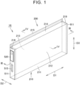
- FIG. 1 is a perspective view illustrating a power storage cell according to an embodiment.
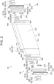
- FIG. 2 is an exploded perspective view of a power storage cell according to an embodiment.
- FIG. 3 is a cross-sectional view taken along III-III shown in FIG. 1 .
- the power storage cell 10 according to an embodiment includes an electrode body 100, a cell case 200, a positive electrode member 620 as a positive electrode terminal, and a negative electrode member 520 as a negative electrode terminal.
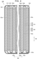
- FIG. 4 is a cross-sectional view taken along IV-IV shown in FIG. 1 .
- the cell case 200 of the power storage cell 10 is omitted, and only the electrode body 100 is illustrated. With reference to FIG. 4 , the details of the electrode body 100 will be described.
- the electrode body 100 includes a plurality of positive electrodes 110, a plurality of negative electrodes 120, and a separator 130.
- the plurality of positive electrodes 110 and the plurality of negative electrodes 120 are arranged alternately in the thickness direction (second direction D2) while being insulated by the separators 130.
- the negative electrodes 120 are formed in a rectangular shape having a length in the widthwise direction (first direction D1) and a width in the height direction (third direction D3).
- the second direction D2 is a direction perpendicular to the first direction D1.
- the third direction D3 is a direction perpendicular to both the first direction D1 and the second direction D2.
- Each negative electrode 120 includes a negative electrode current collector foil 122 and a negative electrode active material layer 124 provided on both surfaces of the negative electrode current collector foil 122.
- the negative electrode current collector foil 122 has a negative electrode tab 122n (see FIG. 3 ) in which the negative electrode active material layers 124 are not provided.
- the negative electrode tab 122n protrudes toward one side in the first direction D1.
- the positive electrodes 110 are formed in a rectangular shape having a length in the first direction D1 and a width in the third direction D3.
- the positive electrode 110 includes a positive electrode collector foil 112 and positive electrode active material layers 114 provided on both surfaces of the positive electrode collector foil 112 in the second direction D2.
- the positive electrode collector foil 112 has a positive electrode tab 112p (see FIG. 3 ) in which the positive electrode active material layers 114 are not provided.
- the positive electrode tab 112p protrudes toward the other side of the first direction D1.
- the separator 130 insulates the positive electrode 110 from the negative electrode 120.
- the separator 130 is made of an insulating material and has minute voids that allow transmission of ions.
- the separator 130 is formed in a zigzag shape.
- the separator 130 has a rectangular shape before being formed into a zigzag-fold shape.
- the separator 130 is disposed while being formed in a zigzag shape between the positive electrode 110 and the negative electrode 120.
- the separators 130 have a plurality of intervening portions 132a, a plurality of first folded portions 132b, a plurality of second folded portions 132c, and an outermost covering portion 132d.
- the intervening portions 132a are interposed between the positive electrode 110 and the negative electrode 120 adjacent to each other in the second direction D2. That is, the intervening portions 132a have a function of insulating the positive electrode 110 and the negative electrode 120 from each other.
- the intervening portions 132a are formed of rectangular regions.
- the first folded portions 132b connect one end portions of the intervening portions 132a adjacent to each other in the second direction D2 on the third direction D3 so that the positive electrode 110 is positioned therebetween.
- the first folded portion 132b is disposed on one side (upper side) of the third direction D3 of the positive electrode 110.
- the second folded portions 132c connect the other end portions of the intervening portions 132a adjacent to each other in the second direction D2 in the third direction D3 so that the negative electrode 120 is positioned therebetween.
- the second folded-back portion 132c is disposed on the other side (lower side) of the third direction D3 of the negative electrode 120.
- the outermost covering portion 132d collectively covers the first folded portion 132b and the second folded portion 132c. More specifically, the outermost covering portion 132d covers all of the positive electrodes 110, all of the negative electrodes 120, all of the intervening portions 132a, all of the first folded portions 132b, and all of the second folded portions 132c together while winding around a central axis parallel to the first direction D1.
- the terminal 132e of the outermost covering portion 132d is set so as not to overlap with the positive electrode active material layer 114 and the negative electrode active material layer 124 in the second direction D2. In the present embodiment, the terminal 132e of the outermost covering portion 132d is provided below the respective positive electrodes 110 and the respective negative electrodes 120.
- An insulating film (not shown) may be coated on a peripheral face and a bottom surface of the plurality of positive electrodes 110, the plurality of negative electrodes 120, and the separator 130.
- the cell case 200 houses the electrode body 100.
- the cell case 200 has a substantially rectangular parallelepiped shape.
- the cell case 200 is configured such that a dimension in the first direction D1 is longer than a dimension in the third direction D3 and a dimension in the second direction D2. Further, the cell case 200 is configured such that a dimension in the third direction D3 is longer than a dimension in the second direction D2.
- the cell case 200 contains an electrode body 100 and an electrolyte (not shown) therein.
- the cell case 200 includes a cylindrical main body portion 210, a first sealing body 510, and a second sealing body 610.
- the cylindrical main body portion 210 is formed with a first opening portion 218 and a second opening portion 219 at both ends thereof in the first direction D1, respectively.
- the first opening portion 218 is provided on one side of the first direction D1.
- the second opening portion 219 is provided on the other side of the first direction D1.
- the cylindrical main body portion 210 is formed by forming the film F into a cylindrical shape. A specific method of forming the cylindrical main body portion 210 will be described later.
- the cylindrical main body portion 210 includes a bottom surface portion 211, a first side surface portion 212, a second side surface portion 213, a top surface portion 214, and a belt-like portion 215.
- the bottom surface portion 211 is located on one side of the third direction D3.
- the bottom surface portion 211 has a rectangular outer shape when viewed from the third direction D3.
- the first side surface portion 212 stands up along the third direction D3 from one end of the bottom surface portion 211 in the second direction D2.
- the second side surface portion 213 stands up along the third direction D3 from the other end of the bottom surface portion 211 in the second direction D2.
- the first side surface portion 212 and the second side surface portion 213 have a rectangular outer shape when viewed from the second direction D2.
- the top surface portion 214 is located on the other side of the third direction D3.
- the top surface portion 214 has a rectangular outer shape when viewed from the third direction D3.
- the top surface portion 214 connects the upper end portions of the first side surface portion 212 and the second side surface portion 213. In the present embodiment, the top surface portion 214 extends from the first side surface portion 212.
- the top surface portion 214 is connected to the second side surface portion 213 via the belt-like portion 215.
- the belt-like portion 215 is formed by joining the first side end portion FE1 and the second side end portion FE2 located at both ends of the film F to each other.
- the strip 215 extends along the first direction D1.
- the belt-like portion 215 extends to the outside of the cell case 200.
- the belt-like portion 215 connects the top surface portion 214 and the second side surface portion 213.
- the position of the belt-shaped portion 215 is not particularly limited.
- the belt-like portion 215 may connect the top surface portion 214 and the first side surface portion 212, may connect the bottom surface portion 211 and the first side surface portion 212, or may connect the bottom surface portion 211 and the second side surface portion 213.
- the first opening portion 218 is formed by one end of the bottom surface portion 211, the first side surface portion 212, the second side surface portion 213, and the top surface portion 214.
- the second opening portion 219 is formed at the other end thereof.
- the first sealing body 510 closes the first opening portion 218.
- the first sealing body 510 has a (first) outer peripheral face 511S in contact with the inner peripheral face 210S of the cylindrical main body portion 210.
- the entire first sealing body 510 is positioned on the inner peripheral face 210S of the cylindrical main body portion 210.
- FIG. 5 is an enlarged partial cross-sectional view of the region V of FIG. 3 .
- the outer peripheral face 511S has a (first) main body surface portion 511Sa and a (first) protruding portion 511Sb.
- the main body surface portion 511Sa extends parallel to the first direction D1 in which the first opening portion 218 and the second opening portion 219 are arranged (see FIG. 5 ).
- the protruding portion 511Sb protrudes from the main body surface portion 511Sa toward the cylindrical main body portion 210.
- the protruding portion 511Sb extends annularly along the circumference of the inner peripheral face 210S of the cylindrical main body portion 210 (see FIG. 2 ).
- the first sealing body 510 includes a first plate-shaped portion 511 and a first extending portion 512. Specifically, the first plate-shaped portion 511 has the above-described outer peripheral face 511S.
- the first plate-shaped portion 511 has a flat plate shape.
- the first plate-shaped portion 511 extends parallel to an imaginary plane perpendicular to the first direction D1 in which the first opening portion 218 and the second opening portion 219 are arranged. That is, the first plate-shaped portion 511 is positioned on the inner peripheral face 210S of the cylindrical main body portion 210.
- the first plate-shaped portion 511 is made of a metal such as aluminum.
- the first plate-shaped portion 511 is provided with a negative electrode member 520.
- the first plate-shaped portion 511 is provided with a pressure release valve 515.
- the pressure release valve 515 is provided so as to break when the internal pressure of the cell case 200 becomes equal to or higher than a predetermined pressure. When the pressure release valve 515 breaks, the gas in the cell case 200 is discharged to the outside of the cell case 200. Therefore, the internal pressure in the cell case 200 decreases.
- the first extending portion 512 extends from the first plate-shaped portion 511 in the first direction D1.
- the first extending portion 512 is disposed on the inner peripheral face 210S of the cylindrical main body portion 210 (see FIG. 3 ).
- the first extending portion 512 extends along the inner peripheral face 210S of the cylindrical main body portion 210 and has a cylindrical outer shape (see FIG. 2 ). Specifically, the first extending portion 512 has a rectangular cylindrical outer shape.
- the first extending portion 512 is joined to the inner peripheral face 210S of the cylindrical main body portion 210.
- the first extending portion 512 has an inner layer portion 512a and an outer layer portion 512b.
- the inner layer portion 512a is integrally formed with the first plate-shaped portion 511. That is, the first plate-shaped portion 511 is made of a metal such as aluminum.
- the outer layer portion 512b is disposed between the inner layer portion 512a and the cylindrical main body portion 210.
- the outer layer portion 512b is made of plastic.
- the outer layer portion 512b is joined to the inner peripheral face 210S of the cylindrical main body portion 210 by thermal welding.
- the negative electrode member 520 is provided on the outer surface of the first plate-shaped portion 511.
- the negative electrode member 520 functions as a negative electrode terminal.
- the negative electrode member 520 includes a negative electrode terminal plate 521 and an insulating plate 522.
- the negative electrode terminal plate 521 is formed in a substantially rectangular parallelepiped shape.
- the negative electrode terminal plate 521 is held by an insulating plate 522.
- the insulating plate 522 is fixed to the outer surface of the first plate-shaped portion 511.
- the insulating plate 522 insulates the first plate-shaped portion 511 from the negative electrode terminal plate 521.
- Each of the negative electrode terminal plate 521 and the insulating plate 522 is provided with a through hole through which a negative electrode connecting pin 533 described later is inserted.
- the second sealing body 610 closes the second opening portion 219.
- the second sealing body 610 has a second outer peripheral face 611S in contact with the inner peripheral face 210S of the cylindrical main body portion 210.
- the entire second sealing body 610 is positioned on the inner peripheral face 210S of the cylindrical main body portion 210.
- the second outer peripheral face 611S has a second main body surface portion 611Sa and a second protruding portion 611Sb.
- the second main body surface portion 611Sa extends parallel to the first direction D1.
- the second protruding portion 611Sb protrudes from the second main body surface portion 611Sa toward the cylindrical main body portion 210.
- the second protruding portion 611Sb extends annularly along the circumference of the inner peripheral face 210S of the cylindrical main body portion 210.
- the second sealing body 610 includes a second plate-shaped portion 611 and a second extending portion 612. Specifically, the second plate-shaped portion 611 has the above-described second outer peripheral face 611S.
- the second plate-shaped portion 611 has a flat plate shape.
- the second plate-shaped portion 611 extends parallel to an imaginary plane perpendicular to the first direction D1. That is, the second plate-shaped portion 611 extends parallel to both the second direction D2 and the third direction D3.
- the second plate-shaped portion 611 is located on the inner peripheral face 210S of the cylindrical main body portion 210.
- the second plate-shaped portion 611 is made of a metal such as aluminum.
- the second plate-shaped portion 611 is provided with a positive electrode member 620.
- the second plate-shaped portion 611 is provided with a pressure release valve 615.
- the pressure release valve 615 is provided so as to break when the internal pressure of the cell case 200 becomes equal to or higher than a predetermined pressure. When the pressure release valve 615 is broken, the gas in the cell case 200 is discharged to the outside of the cell case 200, and thus the internal pressure in the cell case 200 is lowered.
- the second extending portion 612 extends from the second plate-shaped portion 611 in the first direction D1.
- the second extending portion 612 is disposed on the inner peripheral face 210S of the cylindrical main body portion 210 (see FIG. 3 ).
- the second extending portion 612 extends along the inner peripheral face 210S of the cylindrical main body portion 210 and has a cylindrical outer shape (see FIG. 2 ). Specifically, the second extending portion 612 has a rectangular cylindrical outer shape.
- the second extending portion 612 is joined to the inner peripheral face 210S of the cylindrical main body portion 210.
- the second extending portion 612 has an inner layer portion 612a and an outer layer portion 612b.
- the inner layer portion 612a is integrally formed with the second plate-shaped portion 611. That is, the second plate-shaped portion 611 is made of a metal such as aluminum.
- the outer layer portion 612b is disposed between the inner layer portion 612a and the cylindrical main body portion 210.
- the outer layer portion 612b is made of plastic.
- the outer layer portion 612b is joined to the inner peripheral face 210S of the cylindrical main body portion 210 by thermal welding.
- the positive electrode member 620 is provided on the outer surface of the second plate-shaped portion 611.
- the positive electrode member 620 functions as a positive electrode terminal.
- the positive electrode member 620 includes a positive electrode terminal plate 621 and a terminal block 622.
- the positive electrode terminal plate 621 is formed in a rectangular parallelepiped shape.
- the positive electrode terminal plate 621 is made of a metal such as aluminum.
- the terminal block 622 is formed in a rectangular parallelepiped shape.
- the terminal block 622 is made of a metal (iron or the like) different from the metal constituting the positive electrode terminal plate 621.
- the terminal block 622 is fixed to the outer surface of the second plate-shaped portion 611 by welding or the like.
- the positive electrode terminal plate 621 is fixed to the terminal block 622 by welding or the like.
- the second plate-shaped portion 611 is electrically connected to the positive electrode terminal plate 621 via the terminal block 622, and is charged to the same polarity as the positive electrode terminal plate 621.
- Each of the positive electrode terminal plate 621 and the terminal block 622 has a through hole through which a positive electrode connecting pin 633 described later is inserted.
- the positive electrode member 620, an insulating plate is disposed between the second plate-like portion 611, the positive electrode member 620 and the second sealing body 610 may be electrically insulated.
- an insulating plate may be disposed instead of the terminal block 622, or an insulating plate may be disposed between the terminal block 622 and the second plate-shaped portion 611.
- the power storage cell 10 further includes a negative electrode connecting member 530, a negative electrode side insulating member 550, and an insulator 560 on the negative electrode member 520 side.
- the negative electrode connecting member 530 connects the negative electrode current collector 120N and the negative electrode terminal plate 521.
- the negative electrode current collector 120N is a part of the electrode body 100 formed by bundling a plurality of negative electrode tab 122n to be described later.
- the negative electrode connecting member 530 includes a negative electrode side first current collector 531, a negative electrode side second current collector 532, and a negative electrode connecting pin 533.
- the negative electrode-side first current collector 531 is formed of a thin plate-shaped conductive member.
- the negative electrode-side first current collector 531 is connected to the negative electrode current collector 120N by laser welding, ultrasonic welding, or the like.
- the negative electrode-side second current collector 532 is formed of a thin plate-shaped conductive member.
- the negative-electrode-side second current collector 532 is connected to the negative-electrode-side first current collector 531 by laser welding, ultrasonic welding, or the like.
- the negative electrode-side second current collector 532 has a holding portion 532a that holds the negative electrode connecting pin 533.
- the holding portion 532a has a flat plate shape.
- the holding portion 532a is provided with a through hole, and the base end of the negative electrode connecting pin 533 is inserted.
- the negative electrode connecting pin 533 connects the negative electrode-side second current collector 532 and the negative electrode terminal plate 521.
- the negative electrode connecting pin 533 includes a cylindrical portion. The distal end side of the cylindrical portion passes through the first sealing body 510, the insulating plate 522, and the negative electrode terminal plate 521, and is caulked to the negative electrode terminal plate 521.
- the negative electrode-side insulating member 550 is disposed between the first extending portion 512 and the electrode body 100.
- the negative-electrode-side insulating member 550 is provided with a slit 552 through which the negative-electrode current collector 120N is inserted.
- the first extending portion 512 and the negative-electrode-side insulating member 550 are assembled to each other so that an accommodation space is formed between the first plate-shaped portion 511 and the negative-electrode-side insulating member 550.
- the insulator 560 has a shape that covers the cylindrical portion of the negative electrode connecting pin 533.
- the insulator 560 insulates the negative electrode connecting pin 533 from the cell case 200 (more specifically, the first plate-shaped portion 511).
- the negative electrode member 520, the first sealing body 510, the negative electrode connecting member 530, the negative electrode side insulating member 550, and the insulator 560 are incorporated into the first lid assembly 50.
- the first lid assembly 50 is fixed to the cylindrical main body portion 210 by attaching the first sealing body 510 to the first opening portion 218 while the negative electrode current collector 120N and the negative electrode connecting member 530 are fixed by welding or the like.
- the power storage cell 10 further includes a positive electrode connecting member 630, a positive electrode side insulating member 650, and an insulator 660 on the positive electrode member 620 side.
- the positive electrode connecting member 630 connects the positive electrode current collector 110P and the positive electrode terminal plate 621.
- the positive electrode current collector 110P is a part of the electrode body 100 formed by bundling a plurality of positive electrode tabs 112p described later.
- the positive electrode connecting member 630 includes a positive electrode-side first current collector 631, a positive electrode-side second current collector 632, and a positive electrode connecting pin 633.
- the positive electrode-side first current collector 631 is formed of a thin plate-shaped conductive member.
- the positive electrode-side first current collector 631 is connected to the positive electrode current collector 110P by laser welding, ultrasonic welding, or the like.
- the positive electrode-side second current collector 632 is formed of a thin plate-shaped conductive member.
- the positive electrode-side second current collector 632 is connected to the positive electrode-side first current collector 631 by laser welding, ultrasonic welding, or the like.
- the positive electrode-side second current collector 632 has a holding portion 632a that holds the positive electrode connecting pin 633.
- the holding portion 632a has a flat plate shape.
- the holding portion 632a is provided with a through hole, and the base end of the positive electrode connecting pin 633 is inserted.
- the positive electrode connecting pin 633 connects the positive electrode-side second current collector 632 and the positive electrode terminal plate 621.
- the positive electrode connecting pin 633 includes a cylindrical portion. The distal end side of the cylindrical portion penetrates the second sealing body 610, the terminal block 622, and the positive electrode terminal plate 621, and is crimped to the positive electrode terminal plate 621.
- the positive electrode-side insulating member 650 is disposed between the second extending portion 612 and the electrode body 100.
- the positive electrode-side insulating member 650 is provided with a slit 652 through which the positive electrode current collector 110P is inserted.
- the second extending portion 612 and the positive-electrode-side insulating member 650 are assembled to each other so that an accommodation space is formed between the second plate-shaped portion 611 and the positive-electrode-side insulating member 650.
- the positive-electrode current collector 110P, the positive-electrode-side first current collector 631, and the positive-electrode-side second current collector 632 inserted through the slit 552 are disposed in the accommodation space.
- the insulator 660 has a shape that covers the cylindrical portion of the positive electrode connecting pin 633.
- the insulator 660 insulates the positive electrode connecting pin 633 from the cell case 200 (more specifically, the second plate-shaped portion 611).
- the positive electrode member 620, the second sealing body 610, the positive electrode connecting member 630, the positive electrode-side insulating member 650, and the insulator 660 described above are incorporated into the second lid assembly 60.
- the second lid assembly 60 is fixed to the cylindrical main body portion 210 by attaching the second sealing body 610 to the second opening portion 219 while the positive electrode current collector 110P and the positive electrode connecting member 630 are fixed by welding or the like.
- FIG. 6 is a perspective view schematically showing a state in which the cell case is formed in the power storage cell according to the embodiment.
- the same reference numerals as those of the respective portions corresponding to the cylindrical main body portion 210 are given to the respective portions of the film F.
- the method of forming the cylindrical main body portion 210 includes three welding steps. As illustrated in FIGS. 1 to 3 and 6 , in the first welding step, a portion of the film F corresponding to the bottom surface portion 211, the first side surface portion 212, and the second side surface portion 213 is thermally welded to the first extending portion 512 and the second extending portion 612 while the film F is bent. See FIG. 6 , etc.
- the respective parts of the films F may be bonded to the (first) outer peripheral face 511S and the second outer peripheral face 611S by an adhesive or the like.
- a portion of the film F corresponding to the top surface portion 214 is thermally welded to the first extending portion 512 and the second extending portion 612.
- a part of the film F corresponding to the top surface portion 214 may be adhered to the (first) outer peripheral face 511S and the second outer peripheral face 611S by an adhesive or the like.
- the first side end portion FE1 and the second side end portion FE2 are thermally welded to each other.
- the cylindrical main body portion 210 is formed, and the cylindrical main body portion 210 is sealed by the first sealing body 510 and the second sealing body 610.
- the order of the second welding step and the third welding step is not particularly limited.
- the electrolytic solution is injected (see FIG. 6 ). Specifically, the electrolytic solution is injected into the space formed by the film F, the first sealing body 510, and the second sealing body 610 through the liquid injection pipe P. As described above, by forming the cylindrical main body portion 210 with the film F, even when the cylindrical main body portion 210 is relatively long in the first direction D1, the electrolyte can be easily injected throughout the entire first direction D1.
- the film F in the present embodiment is a so-called laminate film.
- the thickness of the film F is, for example, 70 ⁇ m or more and 220 ⁇ m or less.
- the film F includes a resin layer L1, a metal layer L2, and a second resin layer L3.
- the resin layer L1 constitutes an inner peripheral face 210S of the cylindrical main body portion 210.
- the resin layer L1 includes a (first) hole portion H1 and a second hole portion H2.
- the hole portion H1 is fitted to the protruding portion 511Sb.
- the second hole portion H2 is fitted to the second protruding portion 611Sb.
- the hole portion H1 and the second hole portion H2 penetrate through the resin layer L1.
- the hole portion H1 extends annularly along the protruding portion 511Sb.
- the second hole portion H2 extends annularly along the second protruding portion 611Sb.
- the hole portion H1 and the second hole portion H2 may not be provided.
- the film F (the cylindrical main body portion 210) may be bent along the protruding portion 511Sb.
- the film F (the cylindrical main body portion 210) may be bent along the second protruding portion 611Sb.
- outer layer portion 512b made of resin in the first extending portion 512 is thermally welded to the resin layer L1.
- outer layer portion 612b made of resin in the second extending portion 612 is thermally welded to the resin layer L1.
- the resin layer L1 examples include olefinic resins such as polypropylene (PP) and polyethylene (PE).
- the thickness of the resin layer L1 is, for example, 40 ⁇ m or more and 100 ⁇ m or less.
- the resin layer L1 may include a plurality of resin films made of the above-described materials.
- the metal layer L2 is laminated on the resin layer L1. Accordingly, the moisture permeability of the film F can be lowered.
- the metal layer L2 may be made of, for example, aluminum, aluminum alloy, or stainless steel.
- the thickness of the metal layers L2 is, for example, 30 ⁇ m or more and 60 ⁇ m or less.
- the second resin layer L3 is laminated on the metal layer L2 at a position opposite to the resin layer L1 when viewed from the metal layer L2.
- the second resin layer L3 may be made of, for example, polyethylene terephthalate (PET) or nylon.
- PET polyethylene terephthalate
- the thickness of the resin layer is, for example, 20 ⁇ m or more and 60 ⁇ m or less.
- the second resin layer L3 may include a plurality of resin films made of the above-described materials.
- the power storage cell 10 includes the electrode body 100 and the cell case 200.
- the cell case 200 houses the electrode body 100.
- the cell case 200 includes a cylindrical main body portion 210, a first sealing body 510, and a second sealing body 610.
- the cylindrical main body portion 210 is formed by forming the film F into a cylindrical shape, and the first opening portion 218 and the second opening portion 219 are formed at both ends thereof, respectively.
- the first sealing body 510 closes the first opening portion 218.
- the second sealing body 610 closes the second opening portion 219.
- the first sealing body 510 has an outer peripheral face 511S in contact with the inner peripheral face 210S of the cylindrical main body portion 210.
- the outer peripheral face 511S has a main body surface portion 511Sa and a protruding portion 511Sb.
- the main body surface portion 511Sa extends parallel to the first direction D1 in which the first opening portion 218 and the second opening portion 219 are arranged.
- the protruding portion 511Sb protrudes from the main body surface portion 511Sa toward the cylindrical main body portion 210.
- the cylindrical main body portion 210 of the cell case 200 is formed of the film F, it is possible to increase the dimensional flexibility of the cell case 200 in the first direction D1. Furthermore, even when the cylindrical main body portion 210 is formed from the film F, the space between the inner peripheral face 210S and the outer peripheral face 511S is labyrinth-structured by the main body surface portion 511Sa and the protruding portion 511Sb. Thus, even when the cylindrical main body portion 210 of the cell case 200 is formed from the film F, it is possible to suppress a decrease in the sealing property of the cell case 200.
- the film F includes a resin layer L1 constituting the inner peripheral face 210S of the cylindrical main body portion 210, and a metal layer L2 laminated on the resin layer L1.
- the resin layer L1 has a hole portion H1 that is fitted to the protruding portion 511Sb.
- the thickness of the part of the resin layer L1 between the metal layer L2 and the protruding portion 511Sb is relatively small. Accordingly, the moisture permeability between the metal layers L2 and the protruding portion 511Sb can be further reduced.
- the hole portion H1 penetrates the resin layer L1.
- the protruding portion 511Sb is in contact with the metal layer L2 via the hole portion H1.
- the moisture permeability between the metal layers L2 and the protruding portion 511Sb can be further reduced.
- the protruding portion 511Sb extends annularly along the circumferential direction of the inner peripheral face 210S of the cylindrical main body portion 210.
- the hole portion H1 extends annularly along the protruding portion 511Sb.
- the labyrinth structure is formed by the main body surface portion 511Sa and the protruding portion 511Sb in the entire circumferential direction of the inner peripheral face 210S. As a result, it is possible to further suppress a decrease in the sealing property of the cell case 200.
Landscapes
- Chemical & Material Sciences (AREA)
- Chemical Kinetics & Catalysis (AREA)
- Electrochemistry (AREA)
- General Chemical & Material Sciences (AREA)
- Inorganic Chemistry (AREA)
- Sealing Battery Cases Or Jackets (AREA)
Abstract
In the cell case of the power storage cell according to the present disclosure, the cylindrical main body portion is formed by forming a film into a cylindrical shape, and the first opening portion and the second opening portion are formed at both ends thereof, respectively. The first sealing body closes the first opening portion. The second sealing body closes the second opening portion. The first sealing body includes an outer peripheral face that is in contact with an inner peripheral face of the cylindrical main body portion. The outer peripheral face includes a main body surface portion and a protruding portion. The main body surface portion extends in parallel to a first direction in which the first opening portion and the second opening portion are arrayed. The protruding portion protrudes from the main body surface portion toward the cylindrical main body portion.
Description
- The present disclosure relates to a power storage cell.
-
Japanese Unexamined Patent Application Publication No. 2019-106372 JP 2019-106372 A - In a cell case for the battery such as disclosed in
JP 2019-106372 A - The present disclosure has been made in view of the above problem. An object of the present disclosure is to provide a power storage cell that is capable of increasing degree of dimensional freedom of the cell case in the one direction, and also of suppressing deterioration in the sealing property of the cell case.
- A power storage cell according to the present disclosure includes an electrode body and a cell case. The cell case accommodates the electrode body. The cell case includes a cylindrical main body portion, a first sealing body, and a second sealing body. For the cylindrical main body portion, a film is fashioned into a cylindrical shape, with a first opening portion and a second opening portion provided at respective ends. The first sealing body closes the first opening portion. The second sealing body closes the second opening portion. The first sealing body includes an outer peripheral face that is in contact with an inner peripheral face of the cylindrical main body portion. The outer peripheral face includes a main body surface portion and a protruding portion. The main body surface portion extends in parallel to a first direction in which the first opening portion and the second opening portion are arrayed. The protruding portion protrudes from the main body surface portion toward the cylindrical main body portion.
- According to the above configuration, the cylindrical main body portion of the cell case is formed from film. Accordingly, the degree of dimensional freedom of the cell case in the first direction can be increased. Further, even when the cylindrical main body portion is formed from film, space between the inner peripheral face of the cylindrical main body portion and the outer peripheral face of the first sealing body has a labyrinth structure, due to the main body surface portion and the protruding portion. Thus, even when the cylindrical main body portion of the cell case is formed from film, deterioration in the sealing property of the cell case can be suppressed.
- According to the present disclosure, the degree of dimensional freedom of the cell case in the one direction can be increased, and also deterioration in the sealing property of the cell case can be suppressed.
- Features, advantages, and technical and industrial significance of exemplary embodiments of the invention will be described below with reference to the accompanying drawings, in which like signs denote like elements, and wherein:
-
FIG. 1 is a perspective view illustrating a power storage cell according to an embodiment; -
FIG. 2 is an exploded perspective view of a power storage cell according to an embodiment; -
FIG. 3 is a cross-sectional view taken along III-III shown inFIG. 1 ; -
FIG. 4 is a cross-sectional view taken along IV-IV shown inFIG. 1 ; -
FIG. 5 is an enlarged partial cross-sectional view of area V ofFIG. 3 ; and -
FIG. 6 is a perspective view schematically showing a state in which the cell case is formed in the power storage cell according to the embodiment. - Embodiments of the present disclosure will be described with reference to the drawings. In the drawings referred to below, the same or corresponding members are denoted by the same reference numerals.
-
FIG. 1 is a perspective view illustrating a power storage cell according to an embodiment.FIG. 2 is an exploded perspective view of a power storage cell according to an embodiment.FIG. 3 is a cross-sectional view taken along III-III shown inFIG. 1 . As illustrated inFIGS. 1 to 3 , thepower storage cell 10 according to an embodiment includes anelectrode body 100, acell case 200, apositive electrode member 620 as a positive electrode terminal, and anegative electrode member 520 as a negative electrode terminal. -
FIG. 4 is a cross-sectional view taken along IV-IV shown inFIG. 1 . InFIG. 4 , for convenience, thecell case 200 of thepower storage cell 10 is omitted, and only theelectrode body 100 is illustrated. With reference toFIG. 4 , the details of theelectrode body 100 will be described. - As illustrated in
FIG. 4 , theelectrode body 100 includes a plurality ofpositive electrodes 110, a plurality ofnegative electrodes 120, and aseparator 130. The plurality ofpositive electrodes 110 and the plurality ofnegative electrodes 120 are arranged alternately in the thickness direction (second direction D2) while being insulated by theseparators 130. - The
negative electrodes 120 are formed in a rectangular shape having a length in the widthwise direction (first direction D1) and a width in the height direction (third direction D3). The second direction D2 is a direction perpendicular to the first direction D1. The third direction D3 is a direction perpendicular to both the first direction D1 and the second direction D2. Eachnegative electrode 120 includes a negative electrode current collector foil 122 and a negative electrodeactive material layer 124 provided on both surfaces of the negative electrode current collector foil 122. The negative electrode current collector foil 122 has anegative electrode tab 122n (seeFIG. 3 ) in which the negative electrodeactive material layers 124 are not provided. Thenegative electrode tab 122n protrudes toward one side in the first direction D1. - The
positive electrodes 110 are formed in a rectangular shape having a length in the first direction D1 and a width in the third direction D3. Thepositive electrode 110 includes a positiveelectrode collector foil 112 and positive electrodeactive material layers 114 provided on both surfaces of the positiveelectrode collector foil 112 in the second direction D2. The positiveelectrode collector foil 112 has apositive electrode tab 112p (seeFIG. 3 ) in which the positive electrodeactive material layers 114 are not provided. Thepositive electrode tab 112p protrudes toward the other side of the first direction D1. - The
separator 130 insulates thepositive electrode 110 from thenegative electrode 120. Theseparator 130 is made of an insulating material and has minute voids that allow transmission of ions. Theseparator 130 is formed in a zigzag shape. - The
separator 130 has a rectangular shape before being formed into a zigzag-fold shape. Theseparator 130 is disposed while being formed in a zigzag shape between thepositive electrode 110 and thenegative electrode 120. Theseparators 130 have a plurality of interveningportions 132a, a plurality of first foldedportions 132b, a plurality of second foldedportions 132c, and anoutermost covering portion 132d. - The intervening
portions 132a are interposed between thepositive electrode 110 and thenegative electrode 120 adjacent to each other in the second direction D2. That is, the interveningportions 132a have a function of insulating thepositive electrode 110 and thenegative electrode 120 from each other. The interveningportions 132a are formed of rectangular regions. - The first folded
portions 132b connect one end portions of the interveningportions 132a adjacent to each other in the second direction D2 on the third direction D3 so that thepositive electrode 110 is positioned therebetween. The first foldedportion 132b is disposed on one side (upper side) of the third direction D3 of thepositive electrode 110. - The second folded
portions 132c connect the other end portions of the interveningportions 132a adjacent to each other in the second direction D2 in the third direction D3 so that thenegative electrode 120 is positioned therebetween. The second folded-back portion 132c is disposed on the other side (lower side) of the third direction D3 of thenegative electrode 120. - The
outermost covering portion 132d collectively covers the first foldedportion 132b and the second foldedportion 132c. More specifically, theoutermost covering portion 132d covers all of thepositive electrodes 110, all of thenegative electrodes 120, all of the interveningportions 132a, all of the first foldedportions 132b, and all of the second foldedportions 132c together while winding around a central axis parallel to the first direction D1. The terminal 132e of theoutermost covering portion 132d is set so as not to overlap with the positive electrodeactive material layer 114 and the negative electrodeactive material layer 124 in the second direction D2. In the present embodiment, the terminal 132e of theoutermost covering portion 132d is provided below the respectivepositive electrodes 110 and the respectivenegative electrodes 120. An insulating film (not shown) may be coated on a peripheral face and a bottom surface of the plurality ofpositive electrodes 110, the plurality ofnegative electrodes 120, and theseparator 130. - The
cell case 200 houses theelectrode body 100. Thecell case 200 has a substantially rectangular parallelepiped shape. Thecell case 200 is configured such that a dimension in the first direction D1 is longer than a dimension in the third direction D3 and a dimension in the second direction D2. Further, thecell case 200 is configured such that a dimension in the third direction D3 is longer than a dimension in the second direction D2. - The
cell case 200 contains anelectrode body 100 and an electrolyte (not shown) therein. Thecell case 200 includes a cylindricalmain body portion 210, afirst sealing body 510, and asecond sealing body 610. - The cylindrical
main body portion 210 is formed with afirst opening portion 218 and asecond opening portion 219 at both ends thereof in the first direction D1, respectively. Thefirst opening portion 218 is provided on one side of the first direction D1. Thesecond opening portion 219 is provided on the other side of the first direction D1. The cylindricalmain body portion 210 is formed by forming the film F into a cylindrical shape. A specific method of forming the cylindricalmain body portion 210 will be described later. - The cylindrical
main body portion 210 includes abottom surface portion 211, a firstside surface portion 212, a secondside surface portion 213, atop surface portion 214, and a belt-like portion 215. - The
bottom surface portion 211 is located on one side of the third direction D3. Thebottom surface portion 211 has a rectangular outer shape when viewed from the third direction D3. - The first
side surface portion 212 stands up along the third direction D3 from one end of thebottom surface portion 211 in the second direction D2. The secondside surface portion 213 stands up along the third direction D3 from the other end of thebottom surface portion 211 in the second direction D2. The firstside surface portion 212 and the secondside surface portion 213 have a rectangular outer shape when viewed from the second direction D2. - The
top surface portion 214 is located on the other side of the third direction D3. Thetop surface portion 214 has a rectangular outer shape when viewed from the third direction D3. Thetop surface portion 214 connects the upper end portions of the firstside surface portion 212 and the secondside surface portion 213. In the present embodiment, thetop surface portion 214 extends from the firstside surface portion 212. Thetop surface portion 214 is connected to the secondside surface portion 213 via the belt-like portion 215. - The belt-
like portion 215 is formed by joining the first side end portion FE1 and the second side end portion FE2 located at both ends of the film F to each other. - The
strip 215 extends along the first direction D1. The belt-like portion 215 extends to the outside of thecell case 200. As described above, in the present embodiment, the belt-like portion 215 connects thetop surface portion 214 and the secondside surface portion 213. However, the position of the belt-shapedportion 215 is not particularly limited. The belt-like portion 215 may connect thetop surface portion 214 and the firstside surface portion 212, may connect thebottom surface portion 211 and the firstside surface portion 212, or may connect thebottom surface portion 211 and the secondside surface portion 213. - The
first opening portion 218 is formed by one end of thebottom surface portion 211, the firstside surface portion 212, the secondside surface portion 213, and thetop surface portion 214. Thesecond opening portion 219 is formed at the other end thereof. - The
first sealing body 510 closes thefirst opening portion 218. Thefirst sealing body 510 has a (first) outerperipheral face 511S in contact with the innerperipheral face 210S of the cylindricalmain body portion 210. In the present embodiment, the entirefirst sealing body 510 is positioned on the innerperipheral face 210S of the cylindricalmain body portion 210. -
FIG. 5 is an enlarged partial cross-sectional view of the region V ofFIG. 3 . As shown inFIGS. 2 ,3 , and5 , the outerperipheral face 511S has a (first) main body surface portion 511Sa and a (first) protruding portion 511Sb. - The main body surface portion 511Sa extends parallel to the first direction D1 in which the
first opening portion 218 and thesecond opening portion 219 are arranged (seeFIG. 5 ). The protruding portion 511Sb protrudes from the main body surface portion 511Sa toward the cylindricalmain body portion 210. The protruding portion 511Sb extends annularly along the circumference of the innerperipheral face 210S of the cylindrical main body portion 210 (seeFIG. 2 ). - The
first sealing body 510 includes a first plate-shapedportion 511 and a first extendingportion 512. Specifically, the first plate-shapedportion 511 has the above-described outerperipheral face 511S. - The first plate-shaped
portion 511 has a flat plate shape. The first plate-shapedportion 511 extends parallel to an imaginary plane perpendicular to the first direction D1 in which thefirst opening portion 218 and thesecond opening portion 219 are arranged. That is, the first plate-shapedportion 511 is positioned on the innerperipheral face 210S of the cylindricalmain body portion 210. The first plate-shapedportion 511 is made of a metal such as aluminum. The first plate-shapedportion 511 is provided with anegative electrode member 520. - The first plate-shaped
portion 511 is provided with apressure release valve 515. Thepressure release valve 515 is provided so as to break when the internal pressure of thecell case 200 becomes equal to or higher than a predetermined pressure. When thepressure release valve 515 breaks, the gas in thecell case 200 is discharged to the outside of thecell case 200. Therefore, the internal pressure in thecell case 200 decreases. - The first extending
portion 512 extends from the first plate-shapedportion 511 in the first direction D1. The first extendingportion 512 is disposed on the innerperipheral face 210S of the cylindrical main body portion 210 (seeFIG. 3 ). The first extendingportion 512 extends along the innerperipheral face 210S of the cylindricalmain body portion 210 and has a cylindrical outer shape (seeFIG. 2 ). Specifically, the first extendingportion 512 has a rectangular cylindrical outer shape. The first extendingportion 512 is joined to the innerperipheral face 210S of the cylindricalmain body portion 210. - The first extending
portion 512 has aninner layer portion 512a and anouter layer portion 512b. Theinner layer portion 512a is integrally formed with the first plate-shapedportion 511. That is, the first plate-shapedportion 511 is made of a metal such as aluminum. Theouter layer portion 512b is disposed between theinner layer portion 512a and the cylindricalmain body portion 210. Theouter layer portion 512b is made of plastic. Theouter layer portion 512b is joined to the innerperipheral face 210S of the cylindricalmain body portion 210 by thermal welding. - The
negative electrode member 520 is provided on the outer surface of the first plate-shapedportion 511. Thenegative electrode member 520 functions as a negative electrode terminal. Thenegative electrode member 520 includes a negativeelectrode terminal plate 521 and an insulatingplate 522. - The negative
electrode terminal plate 521 is formed in a substantially rectangular parallelepiped shape. The negativeelectrode terminal plate 521 is held by an insulatingplate 522. The insulatingplate 522 is fixed to the outer surface of the first plate-shapedportion 511. The insulatingplate 522 insulates the first plate-shapedportion 511 from the negativeelectrode terminal plate 521. Each of the negativeelectrode terminal plate 521 and the insulatingplate 522 is provided with a through hole through which a negativeelectrode connecting pin 533 described later is inserted. - The
second sealing body 610 closes thesecond opening portion 219. Thesecond sealing body 610 has a second outerperipheral face 611S in contact with the innerperipheral face 210S of the cylindricalmain body portion 210. In the present embodiment, the entiresecond sealing body 610 is positioned on the innerperipheral face 210S of the cylindricalmain body portion 210. - The second outer
peripheral face 611S has a second main body surface portion 611Sa and a second protruding portion 611Sb. - The second main body surface portion 611Sa extends parallel to the first direction D1. The second protruding portion 611Sb protrudes from the second main body surface portion 611Sa toward the cylindrical
main body portion 210. The second protruding portion 611Sb extends annularly along the circumference of the innerperipheral face 210S of the cylindricalmain body portion 210. - The
second sealing body 610 includes a second plate-shapedportion 611 and a second extendingportion 612. Specifically, the second plate-shapedportion 611 has the above-described second outerperipheral face 611S. - The second plate-shaped
portion 611 has a flat plate shape. The second plate-shapedportion 611 extends parallel to an imaginary plane perpendicular to the first direction D1. That is, the second plate-shapedportion 611 extends parallel to both the second direction D2 and the third direction D3. The second plate-shapedportion 611 is located on the innerperipheral face 210S of the cylindricalmain body portion 210. The second plate-shapedportion 611 is made of a metal such as aluminum. The second plate-shapedportion 611 is provided with apositive electrode member 620. - The second plate-shaped
portion 611 is provided with apressure release valve 615. Thepressure release valve 615 is provided so as to break when the internal pressure of thecell case 200 becomes equal to or higher than a predetermined pressure. When thepressure release valve 615 is broken, the gas in thecell case 200 is discharged to the outside of thecell case 200, and thus the internal pressure in thecell case 200 is lowered. - The second extending
portion 612 extends from the second plate-shapedportion 611 in the first direction D1. The second extendingportion 612 is disposed on the innerperipheral face 210S of the cylindrical main body portion 210 (seeFIG. 3 ). The second extendingportion 612 extends along the innerperipheral face 210S of the cylindricalmain body portion 210 and has a cylindrical outer shape (seeFIG. 2 ). Specifically, the second extendingportion 612 has a rectangular cylindrical outer shape. The second extendingportion 612 is joined to the innerperipheral face 210S of the cylindricalmain body portion 210. - The second extending
portion 612 has aninner layer portion 612a and anouter layer portion 612b. Theinner layer portion 612a is integrally formed with the second plate-shapedportion 611. That is, the second plate-shapedportion 611 is made of a metal such as aluminum. Theouter layer portion 612b is disposed between theinner layer portion 612a and the cylindricalmain body portion 210. Theouter layer portion 612b is made of plastic. Theouter layer portion 612b is joined to the innerperipheral face 210S of the cylindricalmain body portion 210 by thermal welding. - The
positive electrode member 620 is provided on the outer surface of the second plate-shapedportion 611. Thepositive electrode member 620 functions as a positive electrode terminal. Thepositive electrode member 620 includes a positiveelectrode terminal plate 621 and aterminal block 622. - The positive
electrode terminal plate 621 is formed in a rectangular parallelepiped shape. The positiveelectrode terminal plate 621 is made of a metal such as aluminum. - The
terminal block 622 is formed in a rectangular parallelepiped shape. Theterminal block 622 is made of a metal (iron or the like) different from the metal constituting the positiveelectrode terminal plate 621. Theterminal block 622 is fixed to the outer surface of the second plate-shapedportion 611 by welding or the like. The positiveelectrode terminal plate 621 is fixed to theterminal block 622 by welding or the like. The second plate-shapedportion 611 is electrically connected to the positiveelectrode terminal plate 621 via theterminal block 622, and is charged to the same polarity as the positiveelectrode terminal plate 621. Each of the positiveelectrode terminal plate 621 and theterminal block 622 has a through hole through which a positiveelectrode connecting pin 633 described later is inserted. - Incidentally, the
positive electrode member 620, an insulating plate is disposed between the second plate-like portion 611, thepositive electrode member 620 and thesecond sealing body 610 may be electrically insulated. In this case, an insulating plate may be disposed instead of theterminal block 622, or an insulating plate may be disposed between theterminal block 622 and the second plate-shapedportion 611. - The
power storage cell 10 further includes a negativeelectrode connecting member 530, a negative electrodeside insulating member 550, and aninsulator 560 on thenegative electrode member 520 side. - The negative
electrode connecting member 530 connects the negative electrodecurrent collector 120N and the negativeelectrode terminal plate 521. The negative electrodecurrent collector 120N is a part of theelectrode body 100 formed by bundling a plurality ofnegative electrode tab 122n to be described later. The negativeelectrode connecting member 530 includes a negative electrode side firstcurrent collector 531, a negative electrode side secondcurrent collector 532, and a negativeelectrode connecting pin 533. - The negative electrode-side first
current collector 531 is formed of a thin plate-shaped conductive member. The negative electrode-side firstcurrent collector 531 is connected to the negative electrodecurrent collector 120N by laser welding, ultrasonic welding, or the like. - The negative electrode-side second
current collector 532 is formed of a thin plate-shaped conductive member. The negative-electrode-side secondcurrent collector 532 is connected to the negative-electrode-side firstcurrent collector 531 by laser welding, ultrasonic welding, or the like. The negative electrode-side secondcurrent collector 532 has a holdingportion 532a that holds the negativeelectrode connecting pin 533. The holdingportion 532a has a flat plate shape. The holdingportion 532a is provided with a through hole, and the base end of the negativeelectrode connecting pin 533 is inserted. - The negative
electrode connecting pin 533 connects the negative electrode-side secondcurrent collector 532 and the negativeelectrode terminal plate 521. The negativeelectrode connecting pin 533 includes a cylindrical portion. The distal end side of the cylindrical portion passes through thefirst sealing body 510, the insulatingplate 522, and the negativeelectrode terminal plate 521, and is caulked to the negativeelectrode terminal plate 521. - The negative electrode-
side insulating member 550 is disposed between the first extendingportion 512 and theelectrode body 100. The negative-electrode-side insulating member 550 is provided with aslit 552 through which the negative-electrodecurrent collector 120N is inserted. - The first extending
portion 512 and the negative-electrode-side insulating member 550 are assembled to each other so that an accommodation space is formed between the first plate-shapedportion 511 and the negative-electrode-side insulating member 550. The negative-electrodecurrent collector 120N, the negative-electrode-side firstcurrent collector 531, and the negative-electrode-side secondcurrent collector 532, which are inserted through theslits 552, are disposed in the accommodation space. - The
insulator 560 has a shape that covers the cylindrical portion of the negativeelectrode connecting pin 533. Theinsulator 560 insulates the negativeelectrode connecting pin 533 from the cell case 200 (more specifically, the first plate-shaped portion 511). - The
negative electrode member 520, thefirst sealing body 510, the negativeelectrode connecting member 530, the negative electrodeside insulating member 550, and theinsulator 560 are incorporated into thefirst lid assembly 50. - The
first lid assembly 50 is fixed to the cylindricalmain body portion 210 by attaching thefirst sealing body 510 to thefirst opening portion 218 while the negative electrodecurrent collector 120N and the negativeelectrode connecting member 530 are fixed by welding or the like. - The
power storage cell 10 further includes a positiveelectrode connecting member 630, a positive electrodeside insulating member 650, and aninsulator 660 on thepositive electrode member 620 side. - The positive
electrode connecting member 630 connects the positive electrodecurrent collector 110P and the positiveelectrode terminal plate 621. The positive electrodecurrent collector 110P is a part of theelectrode body 100 formed by bundling a plurality ofpositive electrode tabs 112p described later. The positiveelectrode connecting member 630 includes a positive electrode-side firstcurrent collector 631, a positive electrode-side secondcurrent collector 632, and a positiveelectrode connecting pin 633. - The positive electrode-side first
current collector 631 is formed of a thin plate-shaped conductive member. The positive electrode-side firstcurrent collector 631 is connected to the positive electrodecurrent collector 110P by laser welding, ultrasonic welding, or the like. - The positive electrode-side second
current collector 632 is formed of a thin plate-shaped conductive member. The positive electrode-side secondcurrent collector 632 is connected to the positive electrode-side firstcurrent collector 631 by laser welding, ultrasonic welding, or the like. The positive electrode-side secondcurrent collector 632 has a holdingportion 632a that holds the positiveelectrode connecting pin 633. The holdingportion 632a has a flat plate shape. The holdingportion 632a is provided with a through hole, and the base end of the positiveelectrode connecting pin 633 is inserted. - The positive
electrode connecting pin 633 connects the positive electrode-side secondcurrent collector 632 and the positiveelectrode terminal plate 621. The positiveelectrode connecting pin 633 includes a cylindrical portion. The distal end side of the cylindrical portion penetrates thesecond sealing body 610, theterminal block 622, and the positiveelectrode terminal plate 621, and is crimped to the positiveelectrode terminal plate 621. - The positive electrode-
side insulating member 650 is disposed between the second extendingportion 612 and theelectrode body 100. The positive electrode-side insulating member 650 is provided with aslit 652 through which the positive electrodecurrent collector 110P is inserted. - The second extending
portion 612 and the positive-electrode-side insulating member 650 are assembled to each other so that an accommodation space is formed between the second plate-shapedportion 611 and the positive-electrode-side insulating member 650. The positive-electrodecurrent collector 110P, the positive-electrode-side firstcurrent collector 631, and the positive-electrode-side secondcurrent collector 632 inserted through theslit 552 are disposed in the accommodation space. - The
insulator 660 has a shape that covers the cylindrical portion of the positiveelectrode connecting pin 633. Theinsulator 660 insulates the positiveelectrode connecting pin 633 from the cell case 200 (more specifically, the second plate-shaped portion 611). - The
positive electrode member 620, thesecond sealing body 610, the positiveelectrode connecting member 630, the positive electrode-side insulating member 650, and theinsulator 660 described above are incorporated into thesecond lid assembly 60. - The
second lid assembly 60 is fixed to the cylindricalmain body portion 210 by attaching thesecond sealing body 610 to thesecond opening portion 219 while the positive electrodecurrent collector 110P and the positiveelectrode connecting member 630 are fixed by welding or the like. - Hereinafter, a method of molding the cylindrical
main body portion 210 using the film F will be described.FIG. 6 is a perspective view schematically showing a state in which the cell case is formed in the power storage cell according to the embodiment. InFIG. 6 , the same reference numerals as those of the respective portions corresponding to the cylindricalmain body portion 210 are given to the respective portions of the film F. - In the present embodiment, the method of forming the cylindrical
main body portion 210 includes three welding steps. As illustrated inFIGS. 1 to 3 and6 , in the first welding step, a portion of the film F corresponding to thebottom surface portion 211, the firstside surface portion 212, and the secondside surface portion 213 is thermally welded to the first extendingportion 512 and the second extendingportion 612 while the film F is bent. SeeFIG. 6 , etc. In addition, the respective parts of the films F may be bonded to the (first) outerperipheral face 511S and the second outerperipheral face 611S by an adhesive or the like. - Next, in the second welding step, a portion of the film F corresponding to the
top surface portion 214 is thermally welded to the first extendingportion 512 and the second extendingportion 612. In addition, a part of the film F corresponding to thetop surface portion 214 may be adhered to the (first) outerperipheral face 511S and the second outerperipheral face 611S by an adhesive or the like. - Finally, in the third welding step, the first side end portion FE1 and the second side end portion FE2 are thermally welded to each other. As a result, the cylindrical
main body portion 210 is formed, and the cylindricalmain body portion 210 is sealed by thefirst sealing body 510 and thesecond sealing body 610. The order of the second welding step and the third welding step is not particularly limited. - After the first welding step and before the second welding step and the third welding step, the electrolytic solution is injected (see
FIG. 6 ). Specifically, the electrolytic solution is injected into the space formed by the film F, thefirst sealing body 510, and thesecond sealing body 610 through the liquid injection pipe P. As described above, by forming the cylindricalmain body portion 210 with the film F, even when the cylindricalmain body portion 210 is relatively long in the first direction D1, the electrolyte can be easily injected throughout the entire first direction D1. - Next, a film constituting the cylindrical
main body portion 210 will be described. As shown inFIG. 5 , the film F in the present embodiment is a so-called laminate film. The thickness of the film F is, for example, 70 µm or more and 220 µm or less. The film F includes a resin layer L1, a metal layer L2, and a second resin layer L3. - The resin layer L1 constitutes an inner
peripheral face 210S of the cylindricalmain body portion 210. In the present embodiment, the resin layer L1 includes a (first) hole portion H1 and a second hole portion H2. The hole portion H1 is fitted to the protruding portion 511Sb. The second hole portion H2 is fitted to the second protruding portion 611Sb. The hole portion H1 and the second hole portion H2 penetrate through the resin layer L1. The hole portion H1 extends annularly along the protruding portion 511Sb. The second hole portion H2 extends annularly along the second protruding portion 611Sb. - Note that the hole portion H1 and the second hole portion H2 may not be provided. When the hole portion H1 is not provided in the resin layer L1, the film F (the cylindrical main body portion 210) may be bent along the protruding portion 511Sb. When the second hole portion H2 is not provided in the resin layer L1, the film F (the cylindrical main body portion 210) may be bent along the second protruding portion 611Sb.
- Further, the
outer layer portion 512b made of resin in the first extendingportion 512 is thermally welded to the resin layer L1. Similarly, theouter layer portion 612b made of resin in the second extendingportion 612 is thermally welded to the resin layer L1. - Examples of the resin layer L1 include olefinic resins such as polypropylene (PP) and polyethylene (PE). The thickness of the resin layer L1 is, for example, 40 µm or more and 100 µm or less. The resin layer L1 may include a plurality of resin films made of the above-described materials.
- The metal layer L2 is laminated on the resin layer L1. Accordingly, the moisture permeability of the film F can be lowered. The metal layer L2 may be made of, for example, aluminum, aluminum alloy, or stainless steel. The thickness of the metal layers L2 is, for example, 30 µm or more and 60 µm or less.
- The second resin layer L3 is laminated on the metal layer L2 at a position opposite to the resin layer L1 when viewed from the metal layer L2. The second resin layer L3 may be made of, for example, polyethylene terephthalate (PET) or nylon. The thickness of the resin layer is, for example, 20 µm or more and 60 µm or less. The second resin layer L3 may include a plurality of resin films made of the above-described materials.
- As described above, the
power storage cell 10 according to the embodiment of the present disclosure includes theelectrode body 100 and thecell case 200. Thecell case 200 houses theelectrode body 100. Thecell case 200 includes a cylindricalmain body portion 210, afirst sealing body 510, and asecond sealing body 610. The cylindricalmain body portion 210 is formed by forming the film F into a cylindrical shape, and thefirst opening portion 218 and thesecond opening portion 219 are formed at both ends thereof, respectively. Thefirst sealing body 510 closes thefirst opening portion 218. Thesecond sealing body 610 closes thesecond opening portion 219. Thefirst sealing body 510 has an outerperipheral face 511S in contact with the innerperipheral face 210S of the cylindricalmain body portion 210. The outerperipheral face 511S has a main body surface portion 511Sa and a protruding portion 511Sb. The main body surface portion 511Sa extends parallel to the first direction D1 in which thefirst opening portion 218 and thesecond opening portion 219 are arranged. The protruding portion 511Sb protrudes from the main body surface portion 511Sa toward the cylindricalmain body portion 210. - According to the above-described configuration, since the cylindrical
main body portion 210 of thecell case 200 is formed of the film F, it is possible to increase the dimensional flexibility of thecell case 200 in the first direction D1. Furthermore, even when the cylindricalmain body portion 210 is formed from the film F, the space between the innerperipheral face 210S and the outerperipheral face 511S is labyrinth-structured by the main body surface portion 511Sa and the protruding portion 511Sb. Thus, even when the cylindricalmain body portion 210 of thecell case 200 is formed from the film F, it is possible to suppress a decrease in the sealing property of thecell case 200. - In addition, in the present embodiment, the film F includes a resin layer L1 constituting the inner
peripheral face 210S of the cylindricalmain body portion 210, and a metal layer L2 laminated on the resin layer L1. The resin layer L1 has a hole portion H1 that is fitted to the protruding portion 511Sb. - According to the above configuration, the thickness of the part of the resin layer L1 between the metal layer L2 and the protruding portion 511Sb is relatively small. Accordingly, the moisture permeability between the metal layers L2 and the protruding portion 511Sb can be further reduced.
- In the present embodiment, the hole portion H1 penetrates the resin layer L1. The protruding portion 511Sb is in contact with the metal layer L2 via the hole portion H1.
- According to the above configuration, the moisture permeability between the metal layers L2 and the protruding portion 511Sb can be further reduced.
- In addition, in the present embodiment, the protruding portion 511Sb extends annularly along the circumferential direction of the inner
peripheral face 210S of the cylindricalmain body portion 210. The hole portion H1 extends annularly along the protruding portion 511Sb. - According to the above-described configuration, the labyrinth structure is formed by the main body surface portion 511Sa and the protruding portion 511Sb in the entire circumferential direction of the inner
peripheral face 210S. As a result, it is possible to further suppress a decrease in the sealing property of thecell case 200. - It should be understood that the embodiments disclosed herein are illustrative and non-restrictive in all respects. The scope of the invention is indicated by the appended claims rather than by the foregoing description of the embodiments. Furthermore, the scope of the present invention includes all modifications within the meaning and range equivalent to the scope of the claims.
Claims (4)
- A power storage cell, comprising:an electrode body; anda cell case for accommodating the electrode body, whereinthe cell case includesa cylindrical main body portion in which a film is fashioned into a cylindrical shape, with a first opening portion and a second opening portion provided at respective ends,a first sealing body for closing the first opening portion, anda second sealing body for closing the second opening portion,the first sealing body includes an outer peripheral face that adheres to an inner peripheral face of the cylindrical main body portion, andthe outer peripheral face includes a main body surface portion extending in parallel to a first direction in which the first opening portion and the second opening portion are arrayed, and a protruding portion protruding from the main body surface portion toward the cylindrical main body portion.
- The power storage cell according to claim 1, whereinthe film includes a resin layer making up the inner peripheral face of the cylindrical main body portion, and a metal layer laminated on the resin layer, anda hole portion, to which the protruding portion is fitted, is provided in the resin layer.
- The power storage cell according to claim 2, whereinthe hole portion passes through the resin layer, andthe protruding portion is in contact with the metal layer via the hole portion.
- The power storage cell according to claim 2 or claim 3, whereinthe protruding portion extends in an annular shape along a circumferential direction of the inner peripheral face of the cylindrical main body portion, andthe hole portion extends in an annular shape along the protruding portion.
Applications Claiming Priority (1)
| Application Number | Priority Date | Filing Date | Title |
|---|---|---|---|
| JP2023117271A JP7859402B2 (en) | 2023-07-19 | Energy storage cell |
Publications (1)
| Publication Number | Publication Date |
|---|---|
| EP4513639A1 true EP4513639A1 (en) | 2025-02-26 |
Family
ID=91950374
Family Applications (1)
| Application Number | Title | Priority Date | Filing Date |
|---|---|---|---|
| EP24188560.7A Pending EP4513639A1 (en) | 2023-07-19 | 2024-07-15 | Power storage cell |
Country Status (4)
| Country | Link |
|---|---|
| US (1) | US20250030095A1 (en) |
| EP (1) | EP4513639A1 (en) |
| KR (1) | KR102896653B1 (en) |
| CN (2) | CN223123996U (en) |
Citations (4)
| Publication number | Priority date | Publication date | Assignee | Title |
|---|---|---|---|---|
| US20120064391A1 (en) * | 2010-09-14 | 2012-03-15 | Denso Corporation | Sealed battery |
| JP2019106372A (en) | 2017-12-12 | 2019-06-27 | 三星電子株式会社Samsung Electronics Co.,Ltd. | Battery case, battery, and method for fabricating battery |
| US20230049457A1 (en) * | 2020-12-21 | 2023-02-16 | Contemporary Amperex Technology Co., Limited | Battery cell, battery, and electric apparatus |
| US20230178827A1 (en) * | 2021-12-06 | 2023-06-08 | Toyota Jidosha Kabushiki Kaisha | Secondary battery |
Family Cites Families (2)
| Publication number | Priority date | Publication date | Assignee | Title |
|---|---|---|---|---|
| CN217655971U (en) | 2022-06-28 | 2022-10-25 | 蜂巢能源科技股份有限公司 | Battery Covers, Batteries and Energy Storage Devices |
| CN218351675U (en) | 2022-07-13 | 2023-01-20 | 力神(青岛)新能源有限公司 | Novel battery structure |
-
2024
- 2024-06-13 US US18/742,509 patent/US20250030095A1/en active Pending
- 2024-07-15 EP EP24188560.7A patent/EP4513639A1/en active Pending
- 2024-07-16 KR KR1020240093460A patent/KR102896653B1/en active Active
- 2024-07-16 CN CN202421675339.7U patent/CN223123996U/en active Active
- 2024-07-16 CN CN202410952006.2A patent/CN119340561A/en active Pending
Patent Citations (4)
| Publication number | Priority date | Publication date | Assignee | Title |
|---|---|---|---|---|
| US20120064391A1 (en) * | 2010-09-14 | 2012-03-15 | Denso Corporation | Sealed battery |
| JP2019106372A (en) | 2017-12-12 | 2019-06-27 | 三星電子株式会社Samsung Electronics Co.,Ltd. | Battery case, battery, and method for fabricating battery |
| US20230049457A1 (en) * | 2020-12-21 | 2023-02-16 | Contemporary Amperex Technology Co., Limited | Battery cell, battery, and electric apparatus |
| US20230178827A1 (en) * | 2021-12-06 | 2023-06-08 | Toyota Jidosha Kabushiki Kaisha | Secondary battery |
Also Published As
| Publication number | Publication date |
|---|---|
| JP2025014586A (en) | 2025-01-30 |
| CN119340561A (en) | 2025-01-21 |
| US20250030095A1 (en) | 2025-01-23 |
| KR102896653B1 (en) | 2025-12-08 |
| KR20250015924A (en) | 2025-02-03 |
| CN223123996U (en) | 2025-07-18 |
Similar Documents
| Publication | Publication Date | Title |
|---|---|---|
| JP7694432B2 (en) | secondary battery | |
| JP4436587B2 (en) | Battery and battery pack | |
| CN102859747B (en) | Secondary battery | |
| US8703326B2 (en) | Rechargeable battery and method for manufacturing the same | |
| KR102896640B1 (en) | Secondary battery | |
| US10177363B2 (en) | Prismatic secondary battery | |
| JP2007134233A (en) | Battery terminal structure | |
| JP2026042085A (en) | Energy storage cell | |
| KR102896653B1 (en) | Power storage cell | |
| WO2024142444A1 (en) | Rectangular secondary battery | |
| JP7859402B2 (en) | Energy storage cell | |
| EP4654372A1 (en) | Battery cell, battery pack comprising same, vehicle, and manufacturing method therefor | |
| EP4742344A1 (en) | Electrode assembly | |
| EP4528907B1 (en) | Secondary battery | |
| EP4718620A1 (en) | Current collector and battery | |
| US20250087834A1 (en) | Electrode assembly and rechargeable battery including the same | |
| EP4712182A1 (en) | Current collector and battery | |
| US20250015397A1 (en) | Method of manufacturing battery case | |
| US20250007048A1 (en) | Secondary battery | |
| EP4742345A1 (en) | Wound electrode assembly | |
| US20230155187A1 (en) | Electrochemical element for a battery and corresponding battery | |
| JP2026084382A (en) | Winding electrode | |
| KR20260071116A (en) | Wound electrode assembly | |
| JP2025140066A (en) | Power storage device | |
| CN121216082A (en) | Electrode plates for batteries and their manufacturing method |
Legal Events
| Date | Code | Title | Description |
|---|---|---|---|
| PUAI | Public reference made under article 153(3) epc to a published international application that has entered the european phase |
Free format text: ORIGINAL CODE: 0009012 |
|
| STAA | Information on the status of an ep patent application or granted ep patent |
Free format text: STATUS: REQUEST FOR EXAMINATION WAS MADE |
|
| 17P | Request for examination filed |
Effective date: 20240728 |
|
| AK | Designated contracting states |
Kind code of ref document: A1 Designated state(s): AL AT BE BG CH CY CZ DE DK EE ES FI FR GB GR HR HU IE IS IT LI LT LU LV MC ME MK MT NL NO PL PT RO RS SE SI SK SM TR |