EP4513621A1 - Battery pack - Google Patents
Battery pack Download PDFInfo
- Publication number
- EP4513621A1 EP4513621A1 EP23217213.0A EP23217213A EP4513621A1 EP 4513621 A1 EP4513621 A1 EP 4513621A1 EP 23217213 A EP23217213 A EP 23217213A EP 4513621 A1 EP4513621 A1 EP 4513621A1
- Authority
- EP
- European Patent Office
- Prior art keywords
- battery pack
- heat exchange
- exchange plate
- holes
- portions
- Prior art date
- Legal status (The legal status is an assumption and is not a legal conclusion. Google has not performed a legal analysis and makes no representation as to the accuracy of the status listed.)
- Pending
Links
Images





Classifications
-
- H—ELECTRICITY
- H01—ELECTRIC ELEMENTS
- H01M—PROCESSES OR MEANS, e.g. BATTERIES, FOR THE DIRECT CONVERSION OF CHEMICAL ENERGY INTO ELECTRICAL ENERGY
- H01M50/00—Constructional details or processes of manufacture of the non-active parts of electrochemical cells other than fuel cells, e.g. hybrid cells
- H01M50/20—Mountings; Secondary casings or frames; Racks, modules or packs; Suspension devices; Shock absorbers; Transport or carrying devices; Holders
- H01M50/233—Mountings; Secondary casings or frames; Racks, modules or packs; Suspension devices; Shock absorbers; Transport or carrying devices; Holders characterised by physical properties of casings or racks, e.g. dimensions
- H01M50/242—Mountings; Secondary casings or frames; Racks, modules or packs; Suspension devices; Shock absorbers; Transport or carrying devices; Holders characterised by physical properties of casings or racks, e.g. dimensions adapted for protecting batteries against vibrations, collision impact or swelling
-
- H—ELECTRICITY
- H01—ELECTRIC ELEMENTS
- H01M—PROCESSES OR MEANS, e.g. BATTERIES, FOR THE DIRECT CONVERSION OF CHEMICAL ENERGY INTO ELECTRICAL ENERGY
- H01M50/00—Constructional details or processes of manufacture of the non-active parts of electrochemical cells other than fuel cells, e.g. hybrid cells
- H01M50/10—Primary casings; Jackets or wrappings
- H01M50/102—Primary casings; Jackets or wrappings characterised by their shape or physical structure
- H01M50/103—Primary casings; Jackets or wrappings characterised by their shape or physical structure prismatic or rectangular
-
- H—ELECTRICITY
- H01—ELECTRIC ELEMENTS
- H01M—PROCESSES OR MEANS, e.g. BATTERIES, FOR THE DIRECT CONVERSION OF CHEMICAL ENERGY INTO ELECTRICAL ENERGY
- H01M10/00—Secondary cells; Manufacture thereof
- H01M10/60—Heating or cooling; Temperature control
- H01M10/61—Types of temperature control
- H01M10/613—Cooling or keeping cold
-
- H—ELECTRICITY
- H01—ELECTRIC ELEMENTS
- H01M—PROCESSES OR MEANS, e.g. BATTERIES, FOR THE DIRECT CONVERSION OF CHEMICAL ENERGY INTO ELECTRICAL ENERGY
- H01M10/00—Secondary cells; Manufacture thereof
- H01M10/60—Heating or cooling; Temperature control
- H01M10/64—Heating or cooling; Temperature control characterised by the shape of the cells
- H01M10/647—Prismatic or flat cells, e.g. pouch cells
-
- H—ELECTRICITY
- H01—ELECTRIC ELEMENTS
- H01M—PROCESSES OR MEANS, e.g. BATTERIES, FOR THE DIRECT CONVERSION OF CHEMICAL ENERGY INTO ELECTRICAL ENERGY
- H01M10/00—Secondary cells; Manufacture thereof
- H01M10/60—Heating or cooling; Temperature control
- H01M10/65—Means for temperature control structurally associated with the cells
- H01M10/655—Solid structures for heat exchange or heat conduction
- H01M10/6556—Solid parts with flow channel passages or pipes for heat exchange
-
- H—ELECTRICITY
- H01—ELECTRIC ELEMENTS
- H01M—PROCESSES OR MEANS, e.g. BATTERIES, FOR THE DIRECT CONVERSION OF CHEMICAL ENERGY INTO ELECTRICAL ENERGY
- H01M10/00—Secondary cells; Manufacture thereof
- H01M10/60—Heating or cooling; Temperature control
- H01M10/65—Means for temperature control structurally associated with the cells
- H01M10/656—Means for temperature control structurally associated with the cells characterised by the type of heat-exchange fluid
-
- H—ELECTRICITY
- H01—ELECTRIC ELEMENTS
- H01M—PROCESSES OR MEANS, e.g. BATTERIES, FOR THE DIRECT CONVERSION OF CHEMICAL ENERGY INTO ELECTRICAL ENERGY
- H01M50/00—Constructional details or processes of manufacture of the non-active parts of electrochemical cells other than fuel cells, e.g. hybrid cells
- H01M50/20—Mountings; Secondary casings or frames; Racks, modules or packs; Suspension devices; Shock absorbers; Transport or carrying devices; Holders
- H01M50/204—Racks, modules or packs for multiple batteries or multiple cells
- H01M50/207—Racks, modules or packs for multiple batteries or multiple cells characterised by their shape
- H01M50/209—Racks, modules or packs for multiple batteries or multiple cells characterised by their shape adapted for prismatic or rectangular cells
-
- H—ELECTRICITY
- H01—ELECTRIC ELEMENTS
- H01M—PROCESSES OR MEANS, e.g. BATTERIES, FOR THE DIRECT CONVERSION OF CHEMICAL ENERGY INTO ELECTRICAL ENERGY
- H01M50/00—Constructional details or processes of manufacture of the non-active parts of electrochemical cells other than fuel cells, e.g. hybrid cells
- H01M50/20—Mountings; Secondary casings or frames; Racks, modules or packs; Suspension devices; Shock absorbers; Transport or carrying devices; Holders
- H01M50/271—Lids or covers for the racks or secondary casings
- H01M50/273—Lids or covers for the racks or secondary casings characterised by the material
- H01M50/276—Inorganic material
-
- H—ELECTRICITY
- H01—ELECTRIC ELEMENTS
- H01M—PROCESSES OR MEANS, e.g. BATTERIES, FOR THE DIRECT CONVERSION OF CHEMICAL ENERGY INTO ELECTRICAL ENERGY
- H01M50/00—Constructional details or processes of manufacture of the non-active parts of electrochemical cells other than fuel cells, e.g. hybrid cells
- H01M50/20—Mountings; Secondary casings or frames; Racks, modules or packs; Suspension devices; Shock absorbers; Transport or carrying devices; Holders
- H01M50/289—Mountings; Secondary casings or frames; Racks, modules or packs; Suspension devices; Shock absorbers; Transport or carrying devices; Holders characterised by spacing elements or positioning means within frames, racks or packs
-
- H—ELECTRICITY
- H01—ELECTRIC ELEMENTS
- H01M—PROCESSES OR MEANS, e.g. BATTERIES, FOR THE DIRECT CONVERSION OF CHEMICAL ENERGY INTO ELECTRICAL ENERGY
- H01M50/00—Constructional details or processes of manufacture of the non-active parts of electrochemical cells other than fuel cells, e.g. hybrid cells
- H01M50/30—Arrangements for facilitating escape of gases
- H01M50/342—Non-re-sealable arrangements
-
- H—ELECTRICITY
- H01—ELECTRIC ELEMENTS
- H01M—PROCESSES OR MEANS, e.g. BATTERIES, FOR THE DIRECT CONVERSION OF CHEMICAL ENERGY INTO ELECTRICAL ENERGY
- H01M50/00—Constructional details or processes of manufacture of the non-active parts of electrochemical cells other than fuel cells, e.g. hybrid cells
- H01M50/30—Arrangements for facilitating escape of gases
- H01M50/342—Non-re-sealable arrangements
- H01M50/3425—Non-re-sealable arrangements in the form of rupturable membranes or weakened parts, e.g. pierced with the aid of a sharp member
-
- H—ELECTRICITY
- H01—ELECTRIC ELEMENTS
- H01M—PROCESSES OR MEANS, e.g. BATTERIES, FOR THE DIRECT CONVERSION OF CHEMICAL ENERGY INTO ELECTRICAL ENERGY
- H01M50/00—Constructional details or processes of manufacture of the non-active parts of electrochemical cells other than fuel cells, e.g. hybrid cells
- H01M50/30—Arrangements for facilitating escape of gases
- H01M50/35—Gas exhaust passages comprising elongated, tortuous or labyrinth-shaped exhaust passages
- H01M50/358—External gas exhaust passages located on the battery cover or case
-
- H—ELECTRICITY
- H01—ELECTRIC ELEMENTS
- H01M—PROCESSES OR MEANS, e.g. BATTERIES, FOR THE DIRECT CONVERSION OF CHEMICAL ENERGY INTO ELECTRICAL ENERGY
- H01M10/00—Secondary cells; Manufacture thereof
- H01M10/60—Heating or cooling; Temperature control
- H01M10/65—Means for temperature control structurally associated with the cells
- H01M10/656—Means for temperature control structurally associated with the cells characterised by the type of heat-exchange fluid
- H01M10/6567—Liquids
-
- Y—GENERAL TAGGING OF NEW TECHNOLOGICAL DEVELOPMENTS; GENERAL TAGGING OF CROSS-SECTIONAL TECHNOLOGIES SPANNING OVER SEVERAL SECTIONS OF THE IPC; TECHNICAL SUBJECTS COVERED BY FORMER USPC CROSS-REFERENCE ART COLLECTIONS [XRACs] AND DIGESTS
- Y02—TECHNOLOGIES OR APPLICATIONS FOR MITIGATION OR ADAPTATION AGAINST CLIMATE CHANGE
- Y02E—REDUCTION OF GREENHOUSE GAS [GHG] EMISSIONS, RELATED TO ENERGY GENERATION, TRANSMISSION OR DISTRIBUTION
- Y02E60/00—Enabling technologies; Technologies with a potential or indirect contribution to GHG emissions mitigation
- Y02E60/10—Energy storage using batteries
Definitions
- the disclosure belongs to the technical field of energy storage equipment, and in particular, relates to a battery pack.
- the disclosure provides a battery pack aiming to the problem in the related art that after an explosion-proof valve of a cell is opened, high-temperature and high-pressure substances may easily corrode case.
- the disclosure provides a battery pack including a case and cell assemblies disposed in the case.
- the case includes a heat exchange plate and a bottom protection plate disposed below the heat exchange plate, and the cell assemblies are disposed on the heat exchange plate.
- Each of the cell assemblies includes a plurality of cells, an explosion-proof valve is provided on a side of each of the cells facing the heat exchange plate, and the heat exchange plate is provided with pressure relief through holes corresponding to the explosion-proof valves.
- Reinforcing members are disposed between the heat exchange plate and the bottom protection plate, and each of the reinforcing members includes a base portion and supporting portions connected to the base portion. The base portion is disposed on the bottom protection plate, and the supporting portions are supported between the bottom protection plate and the heat exchange plate. In a height direction of the battery pack, projection of the pressure relief through holes at least partially overlap projection of the base portions.
- the pressure relief through holes are arranged in sequence in a width direction of the battery pack, and each of the base portions is in a long strip shape and extends in the width direction of the battery pack.
- each of the supporting portions is in a long strip shape extending in the width direction of the battery pack.
- the supporting portions are provided on both sides of the base portion in a length direction of the battery pack, and each of the pressure relief through holes is disposed between the two supporting portions.
- lifting portions extending in the width direction of the battery pack are further provided on edges of the supporting portions close to the heat exchange plate, and the lifting portions are attached to the heat exchange plate.
- the two supporting portions are provided with the lifting portions, and the two lifting portions extend away from each other.
- an included angle between the base portion and each of the supporting portions is an obtuse angle.
- the two lifting portions extend toward each other, and the lifting portions are provided with receiving through holes corresponding to the pressure relief through holes.
- the number of the receiving through holes is less than the number of the pressure relief through holes and one of the receiving through holes is disposed corresponding to plural of the pressure relief through holes.
- the number of the receiving through holes corresponds to the number of the pressure relief through holes, and the receiving through holes and the pressure relief through holes are arranged in one-to-one.
- plural cell assemblies are provided, and the cell assemblies are disposed side by side in sequence in the length direction of the battery pack on the heat exchange plate.
- Plural reinforcing members are provided, and the reinforcing members are disposed side by side corresponding to the cell assemblies.
- separating beams extending in the width direction of the battery pack are provided on a side of the heat exchange plate away from the bottom protection plate, and each of the separating beams is located between the two adjacent cell assemblies.
- both ends of each of the separating beams are connected to an inner wall of the case, and a discharge through hole is provided on an outer wall of the case corresponding to an end portion of the separating beam.
- a discharge channel communicating with the discharge through hole is provided in the separating beam, and a communicating through hole communicating with the discharge channel is provided on the heat exchange plate corresponding to the separating beam.
- the heat exchange plate and the bottom protection plate communicate with the discharge through hole through the communicating through hole and the discharge channel.
- each of the separating beams includes a top portion extending in the width direction of the battery pack.
- the top portion is located above the heat exchange plate, and two side portions are provided on both sides of the top portion toward the heat exchange plate. The side portions are connected onto the heat exchange plate and are enclosed with the heat exchange plate and the top portion to form the discharge channel.
- the discharge through holes are provided with waterproof and breathable valves.
- the projection of the pressure relief through hole is within the projection of the base portion.
- a protection layer is provided on a side of the base portion facing the pressure relief through hole and/or a side of the supporting portion close to the base portion.
- the protection layer is made of mica plates.
- heat exchange flow channels for circulating a heat exchange medium are provided in the heat exchange plate.
- the cell assemblies are disposed on the heat exchange plate, and each of the cell assemblies includes plural cells.
- the explosion-proof valves of the cells are all disposed on the sides of the cells facing the heat exchange plate, and the heat exchange plate is provided with the pressure relief through holes corresponding to the explosion-proof valve. In this way, when the explosion-proof valves of the cells are opened, the high-temperature and high-pressure substances ejected by the explosion-proof valves may enter between the heat exchange plate and the bottom protection plate through the corresponding pressure relief through holes for pressure relief.
- the reinforcing members are disposed between the heat exchange plate and the bottom protection plate, and each of the reinforcing members includes the base portion and the supporting portions connected to the base portion.
- the base portions are disposed on the bottom protection plate, and the supporting portions are supported between the bottom protection plate and the heat exchange plate.
- the projections of the pressure relief through holes at least partially overlap the projections of the base portions. Therefore, the reinforcing members support and strengthen the bottom protection plate and the heat exchange plate. Further, after the high-temperature and high-pressure substances enter between the heat exchange plate and the bottom protection plate through the pressure relief through holes, in the height direction of the battery pack, the portions where the projections of the base portions of the reinforcing members overlap the projections of the pressure relief through holes may block the high-temperature and high-pressure substances. In this way, the direct corrosion and impact of the high-temperature and high-pressure substances on the bottom protection plate is reduced, and the risk of the bottom protection plate being penetrated is also lowered.
- this embodiment provides a battery pack 100 including a case 1 and cell assemblies 2 disposed in the case 1.
- the case 1 includes a heat exchange plate 5 and a bottom protection plate 7 disposed below the heat exchange plate 5, and the cell assemblies 2 are disposed on the heat exchange plate 5.
- the heat exchange plate 5 may exchange heat with the cell assemblies 2, so that the cell assemblies 2 are in a suitable temperature range. As such, the working efficiency of the cell assemblies 2 is improved, and the risk of thermal runaway of the cell assemblies 2 is lowered.
- the heat exchange plate 5 may be provided with refrigeration structures such as semiconductor refrigeration fins and heating structures such as heating fins, which may directly generate or absorb heat and exchange heat with the cell assemblies 2.
- heat exchange flow channels 53 for circulating a heat exchange medium is provided in the heat exchange plate 5. The heat exchange medium flows in the heat exchange flow channels 53 and exchanges heat with the cell assemblies 2 through the heat exchange plate 5.
- one cell assembly 2 includes a plurality of cells 20, and an explosion-proof valve 4 is provided on a side of each of the cells 20 facing the heat exchange plate 5.
- the cells 20 are cylindrical, and the cylindrical cells exhibit the advantages of mature winding technology, high production efficiency, and low costs.
- the cells 20 are square, and the square cells exhibit the advantages of simple structures, easy arrangement, and high energy density.
- the heat exchange plate 5 is provided with pressure relief through holes 51 corresponding to the explosion-proof valves 4.
- the pressure relief through holes 51 are arranged to avoid the heat exchange flow channels 53 in the heat exchange plate 5, for example, between adjacent heat exchange flow channels 53, to prevent the heat exchange medium in the heat exchange flow channels 53 from leaking.
- the battery pack 100 has a height direction, a width direction, and a length direction that are perpendicular to one another.
- the height direction of the battery pack 100 is the direction in which the explosion-proof valves 4 on the cells 20 are oriented, that is, the orientation direction of the pressure relief through holes 51.
- Dimensions of the battery pack 100 in the height direction, the width direction, and the length direction are not limited.
- reinforcing members 6 are disposed between the heat exchange plate 5 and the bottom protection plate 7, and each of the reinforcing members 6 includes a base portion 61 and supporting portions 62 connected to the base portion 61.
- the base portion 61 is disposed on the bottom protection plate 7, and the supporting portions 62 are supported between the bottom protection plate 7 and the heat exchange plate 5.
- projection of the pressure relief through holes 51 at least partially overlap projection of the base portions 61.
- the reinforcing members 6 support and strengthen the bottom protection plate 7 and the heat exchange plate 5. After the high-temperature and high-pressure substances enter between the heat exchange plate 5 and the bottom protection plate 7 through the pressure relief through holes 51, in the height direction of the battery pack 100, the portions where the projections of the base portions 61 of the reinforcing members 6 overlap the projections of the pressure relief through holes 51 may block the high-temperature and high-pressure substances. In this way, the corrosion and direct impact of the high-temperature and high-pressure substances on the bottom protection plate 7 is reduced, and the risk of the bottom protection plate 7 being penetrated is also lowered. In this embodiment, in the height direction of the battery pack 100, the projections of the pressure relief through holes 51 is entirely within the projection of the base portion 61.
- the high-temperature and high-pressure substances pass through the pressure relief through holes 51 in the height direction of the battery pack 100, the high-temperature and high-pressure substances are all ejected on the base portions 61.
- an effective protection area of the base portions 61 on the bottom protection plate 7 may be increased, and the protection effect generated by the base portions 61 on the bottom protection plate 7 may be improved.
- the heat exchange plate 5 and the reinforcing members 6 may be connected by laser penetration welding, riveting connection, gluing, etc.
- the reinforcing members 6 may also be connected to the bottom protection plate 7 through various methods such as laser penetration welding, bonding, riveting connection, bolt connection, etc.
- mounting bosses 71 protruding toward the heat exchange plate 5 is provided on the bottom protection plate 7 at positions corresponding to the reinforcing members 6.
- Each of the mounting bosses 71 is provided with a bolt hole, and the reinforcing members 6 are connected onto the mounting bosses 71 through bolts.
- the mounting bosses 71 may reduce a matching area between the bottom protection plate and the reinforcing members 6, so that the overall processing difficulty of the bottom protection plate 7 is lowered.
- the cells 20 of the cell assemblies 2 are stacked in sequence in the width direction of the battery pack 100.
- the pressure relief through holes 51 of the heat exchange plate 5 are also arranged in sequence in the width direction of the battery pack 100.
- Each of the base portions 61 is in a long strip shape and extends in the width direction of the battery pack 100, so that the base portions 61 may correspond to the pressure relief through holes 51 in the width direction of the battery pack 100.
- each of the supporting portions 62 is in a long strip shape extending in the width direction of the battery pack 100.
- the supporting portions 62 are disposed on both sides of the base portion 61 in the length direction of the battery pack 100, and each of the pressure relief through holes 51 is disposed between the two supporting portions 62. Since each of the pressure relief through holes 51 is disposed correspondingly between the two supporting portions 62, the high-temperature and high-pressure substances discharged from the pressure relief through holes 51 may enter between the two supporting portions 62.
- the two supporting portions 62 may block the high-temperature and high-pressure substances between the two supporting portions 62 and constrain a discharge trajectory of the high-temperature and high-pressure substances, so that damage to the battery pack structure outside the reinforcing members 6 by the high-temperature and high-pressure substances is decreased.
- the cell assemblies 2 and the heat exchange plate 5 are bonded through structural glue and thermally conductive glue. Gaps between the cell assemblies 2 and the heat exchange plate 5 filled with structural glue and thermal conductive glue is beneficial to blocking the high-temperature and high-pressure substances. In this way, the risk of the high-temperature and high-pressure substances overflowing to other locations in the case 1 and causing chain thermal runaway of the cells 20 is lowered.
- lifting portions 63 extending in the width direction of the battery pack 100 are further disposed on edges of the supporting portions 62 close to the heat exchange plate, and the lifting portions 63 are attached to the heat exchange plate 5.
- the lifting portion 63 may increase the contact areas between the supporting portions 62 and the heat exchange plate 5, so that the extrusion stress between the supporting portions 62 and the heat exchange plate 5 is reduced, and the strength of the heat exchange plate 5 is improved.
- each of the lifting portions 63 extend toward each other, that is, each of the lifting portions 63 is located between the two supporting portions 62 and is connected to the two supporting portions 62.
- the lifting portions 63 are provided with receiving through holes 60 corresponding to the pressure relief through holes 51.
- Each lifting portion 63 is located between the two supporting portions 62, so that the folding moment endured by the reinforcing member 6 may be reduced and the reinforcing member 6 may be prevented from being deformed.
- each of the reinforcing members 6 is a square tube extending in the width direction of the battery pack 100 in this embodiment.
- the bottom of the square tube is the base portion 61
- the outer walls on both sides of the bottom are the supporting portions 62
- the top of the square tube is the lifting portion 63.
- Each receiving through hole 60 may be sequentially opened on the top of the square tube in the length direction of the square tube through punching or other machine processing methods.
- the square tube may be purchased directly according to the specifications without mold re-opening and processing, so that the production costs of the reinforcing members 6 are reduced.
- the number of the receiving through holes 60 is less than the number of the pressure relief through holes 51, and one of the receiving through holes 60 is disposed corresponding to plural pressure relief through holes 51.
- the arrangement of one receiving through hole 60 corresponding to multiple pressure relief through holes 51 may allow the number of the receiving through holes 60 to be reduced and the processing costs to be lowered.
- the number of the receiving through holes 60 may also correspond to the number of the pressure relief through holes 51, and the receiving through holes 60 and the pressure relief through holes 51 are arranged in one-to-one.
- the one-to-one arrangement of the receiving through holes 60 and the pressure relief through holes 51 makes the contact area between the reinforcing members 6 and the heat exchange plate 5 larger. In this way, the lifting effect of lifting the heat exchange plate 5 is improved and stress concentration is reduced.
- the two lifting portions 63 extend away from each other, that is, each of the two supporting portions 62 is provided with the lifting portion 63.
- the lifting portion 63 is located on a side of the corresponding supporting portion 62 away from the other supporting portion 62.
- the lifting portion 63 is a flange formed by the edge of the supporting portion 62 close to the heat exchange plate 5 being folded and extending toward the outside of the supporting portion 62.
- the base portion 61, the supporting portions 62, and the lifting portions 63 of each reinforcing member 6 may all be formed from plate materials through a stamping process.
- the stamping processing is a simple process and has the advantages of low costs and high processing efficiency.
- an included angle between the base portion 61 and each of the supporting portions 62 is an obtuse angle, so that the space between the two supporting portions 62 is increased, and the high-temperature and high-pressure substances may be quickly discharged from the reinforcing members 6.
- plurality cell assemblies 2 are provided in the case 1, and the cell assemblies 2 are disposed side by side in sequence in the length direction of the battery pack 100 on the heat exchange plate 5.
- Plural reinforcing members 6 are provided, and the reinforcing members 6 are disposed side by side corresponding to the cell assemblies 2.
- Increasing the number of the cell assemblies 2 may increase the total energy storage capacity of the battery pack.
- Increasing the number of the reinforcing members 6 may improve the structural strength of the heat exchange plate 5 and the bottom protection plate 7.
- the reinforcing members 6 are arranged corresponding to the cell assemblies 2, so that the extrusion stress of the cell assemblies 2 on the heat exchange plate 5 is relieved, and the heat exchange plate 5 is better supported.
- separating beams 9 extending in the width direction of the battery pack 100 is provided on a side of the heat exchange plate 5 away from the bottom protection plate 7, and each of the separating beams 9 is located between the two adjacent cell assemblies 2.
- separating beams 9 are provided between adjacent battery cell assemblies 2 in the length direction of the battery pack 100.
- the separating beams 9 may support an outer wall of the case 1 in the width direction of the battery pack 100 and improve the structural strength of the case 1.
- each of the separating beams may separate the cell assemblies 2 on both sides of the separating beams 9.
- the separation beam 9 may block the high-temperature and high-pressure substances and reduce the impact of the thermally runaway cell assembly 2 on the adjacent cell assembly 2.
- both ends of each of the separating beams 9 are connected to an inner wall of the case 1, and a discharge through hole 12 is provided on an outer wall of the case 1 corresponding to an end portion of the separating beam 9.
- a discharge channel 8 communicating with the discharge through hole 12 is provided in the separating beam 9, and a communicating through hole 52 communicating with the discharge channel 8 is provided on the heat exchange plate 5 corresponding to the separating beam 9.
- the heat exchange plate 5 and the bottom protection plate 7 communicate with the discharge through hole 12 through the communicating through hole 52 and the discharge channel 8.
- the high-temperature and high-pressure substances discharged between the heat exchange plate 5 and the bottom protection plate 7 may enter the discharge channel 8 through the communicating through hole 52 and then are discharged out of the battery pack 100 through the discharge channel 8 and the discharge through hole 12.
- the discharge channel 8 is arranged in the separating beam 9, so no additional arrangement space is required, so that a volume of the battery pack 100 is reduced and the energy density of the battery pack 100 is increased.
- the size between the heat exchange plate 5 and the bottom protection plate 7 in the height direction of the battery pack 100 is usually relatively narrow.
- the size of the outer wall of the case 1 corresponding to the height direction of the battery pack 100 between the heat exchange plate 5 and the bottom protection plate 7 is correspondingly narrow, making it difficult to arrange the discharge through hole 12.
- the separating beam 9 is provided on the side of the heat exchange plate 5 away from the bottom protection plate 7, so that the outer wall of the case 1 has a sufficient arrangement space on the side of the heat exchange plate 5 away from the bottom protection plate 7 in the height direction of the battery pack 100.
- the discharge through hole 12 is arranged on the outer wall of the case 1 corresponding to the end portion of the separating beam 9 on the side of the heat exchange plate 5 away from the bottom protection plate 7. In this way, the arrangement space of the discharge through hole 12 may be increased, the size of the discharge through hole 12 in the height direction of the battery pack 100 is increased, and the discharge efficiency of the high-temperature and high-pressure substances is further improved.
- the outer wall of the case 1 is a side beam 10 with a tubular structure formed by rolling and processing of high-strength steel.
- the tubular structure exhibits the advantages of high strength and light weight, so that the overall structural strength of the case 1 may be improved.
- the end portion of the separating beam 9 communicates with the inside of the side beam 10.
- the discharge through hole 12 is opened on the side of the side beam 10 close to the outside of the case 1, and the discharge channel 8 in the separating beam 9 communicates with the discharge through hole 12 through the side beam 10.
- the separating beam 9 includes a top portion 91 extending in the width direction of the battery pack 100.
- the top portion is located above the heat exchange plate 5 and two side portions 92 are provided on both sides of the top portion toward the heat exchange plate 5.
- the side portions are connected to the heat exchange plate 5 and are enclosed with the heat exchange plate 5 and the top portion to form the discharge channel 8.
- the edge of each of the side portions 92 is also provided with a flange to be attached to the heat exchange plate 5, so as to facilitate the attachment of the separating beam 9 and the heat exchange plate 5.
- the top portion 91, the side portions 92, and the flanges of the separating beam 9 may be integrally stamped and formed from plates, which has a simple process and requires low costs.
- the side portions 92 of the separating beam 9 are connected onto the heat exchange plate 5.
- the side portions 92, the top portion 91, and the heat exchange plate 5 are closed to form the discharge channel 8, so that there is no need to provide additional structures to form the discharge channel 8, which can make the battery pack 100 lighter and reduce the material costs.
- the discharge through holes 12 are provided with waterproof and breathable valves 11.
- the waterproof and breathable valves 11 open when the high-temperature and high-pressure gas is discharged, so that the high-temperature and high-pressure substances in the case 1 may be discharged in time.
- the waterproof and breathable valves 11 are closed before the high-temperature and high-pressure gas is discharged, is breathable, and may prevent dust and other impurities outside the case 1 from entering the case 1 while balancing the pressure inside and outside the case 1, so that the service life of the battery pack 100 is thereby increased.
- a protection layer 64 is provided on a side of the base portion 61 of the reinforcing member 6 facing the pressure relief through hole 51. In some other embodiments, the protection layer 64 is also provided on sides of the supporting portions 62 of the reinforcing member 6 close to the base portion 61. Providing the protection layer 64 partially on the reinforcing member 6 may reduce the arrangement area of the protection layer 64 and reduce a weight and material costs of the battery pack 100.
- the protection layer 64 is provided on the side of the base portion 61 of the reinforcing member 6 facing the pressure relief through hole 51 and the sides of the supporting portions 62 close to the base portion 61. In this way, the protection range of the protection layer 64 is increased, and the protective effect on the reinforcing member 6 is improved.
- the protection layer 64 may reduce the impact, corrosion, or burning of the reinforcing members 6 caused by the high-temperature and high-pressure gas, so the risk of the bottom protection plate 7 being penetrated by the high-temperature and high-pressure gas is further reduced.
- the protection layer 64 may be a ceramic, silicate, phosphate, or other coating coated on the reinforcing members 6 and has high temperature resistance and certain structural strength, so that the protection layer 64 may reduce the impact and burning of the reinforcing member 6 by the high-temperature and high-pressure gas.
- the protection layer 64 is made of mica plates 65.
- the mica plates 65 may be fixed on the reinforcing members 6 through bonding, bolting, etc., and exhibit the advantages of light weight, good high temperature resistance and insulation performance, and high cost performance.
- the bottom protection plate 7 may be made of aluminum, a composite material, a steel plate, and other materials, and the reinforcing members 6 may be made of aluminum or stainless steel.
- Aluminum is light in weight, which is beneficial to reducing the weight of the battery pack and improving the energy density of the battery pack.
- Stainless steel has good corrosion resistance and high strength, which is beneficial to improving the structural strength between the heat exchange plate 5 and the bottom protection plate 7.
- the cell assemblies 2 are disposed on the heat exchange plate 5, and each of the cell assemblies 2 includes plural cells 20.
- the explosion-proof valves 4 of the cells 20 are all disposed on the sides of the cells 20 facing the heat exchange plate 5, and the heat exchange plate 5 is provided with the pressure relief through holes 51 corresponding to the explosion-proof valves 4.
- the explosion-proof valves 4 of the cells 20 are opened, the high-temperature and high-pressure substances ejected by the explosion-proof valves 4 may enter between the heat exchange plate 5 and the bottom protection plate 7 through the corresponding pressure relief through holes 51 for pressure relief.
- the reinforcing members 6 are disposed between the heat exchange plate 5 and the bottom protection plate 7, and each of the reinforcing members 6 includes the base portion 61 and the supporting portions 62 connected to the base portion 61.
- the base portions 61 are disposed on the bottom protection plate 7, and the supporting portions 62 are supported between the bottom protection plate 7 and the heat exchange plate 5.
- the projections of the pressure relief through holes 51 at least partially overlap the projections of the base portions 61. Therefore, the reinforcing members 6 support and strengthen the bottom protection plate 7 and the heat exchange plate 5.
- the portions where the projections of the base portions 61 of the reinforcing members 6 overlap the projections of the pressure relief through holes 51 may block the high-temperature and high-pressure substances. In this way, the direct impact and corrosion of the high-temperature and high-pressure substances on the bottom protection plate 7 is reduced, and the risk of the bottom protection plate 7 being penetrated is also lowered.
Landscapes
- Chemical & Material Sciences (AREA)
- Chemical Kinetics & Catalysis (AREA)
- Electrochemistry (AREA)
- General Chemical & Material Sciences (AREA)
- Engineering & Computer Science (AREA)
- Manufacturing & Machinery (AREA)
- Inorganic Chemistry (AREA)
- Battery Mounting, Suspending (AREA)
- Secondary Cells (AREA)
- Gas Exhaust Devices For Batteries (AREA)
Abstract
A battery pack (100) including a case (1) and cell assemblies (2) disposed in the case (1). The case (1) includes a heat exchange plate (5) and a bottom protection plate (7) disposed below the heat exchange plate (5). Each cell assembly (2) includes a plurality of cells (20), and an explosion-proof valve (4) is provided on a side of each cell (20) facing the heat exchange plate (5). The heat exchange plate (5) is provided with pressure relief through holes (51) corresponding to the explosion-proof valves (4). Reinforcing members (6) are provided between the heat exchange plate (5) and the bottom protection plate (7), and each reinforcing member includes a base portion (61) disposed on the bottom protection plate (7) and supporting portions connected to the base portion (61) and supported between the bottom protection plate (7) and the heat exchange plate (5).
Description
- The disclosure belongs to the technical field of energy storage equipment, and in particular, relates to a battery pack.
- Generally, the battery pack includes the case and the cell assemblies arranged in the case, and the explosion-proof valves are disposed on the cells of the cell assemblies. When one cell experiences thermal runaway, the internal pressure and temperature of the cell will exceed the safety threshold of the explosion-proof valve, causing the explosion-proof valve to open to relieve pressure in the cell. The high-temperature and high-pressure substances discharged from the explosion-proof valve need to be released in time and discharged out of the case in time to avoid triggering a chain thermal runaway of the surrounding cells and endangering the safety of the entire battery pack. Due to the requirements of lightweight and high energy density of battery packs, the structures inside the case, such as the bottom protection plate, are usually thin and light, and the strength, impact resistance, high temperature resistance and other properties of these structures are poor. When the high-temperature and high-pressure substances are discharged, once the high-temperature and high-pressure substances come into contact with the internal structures of the case, such as the bottom protection plate, these substances may easily corrode the case, damage the structure of the case, or even penetrate through the case, and safety hazards may thus occur.
- In view of the abovementioned shortcomings found in the related art, the disclosure provides a battery pack aiming to the problem in the related art that after an explosion-proof valve of a cell is opened, high-temperature and high-pressure substances may easily corrode case.
- To achieve the above and other related purposes, the disclosure provides a battery pack including a case and cell assemblies disposed in the case. The case includes a heat exchange plate and a bottom protection plate disposed below the heat exchange plate, and the cell assemblies are disposed on the heat exchange plate. Each of the cell assemblies includes a plurality of cells, an explosion-proof valve is provided on a side of each of the cells facing the heat exchange plate, and the heat exchange plate is provided with pressure relief through holes corresponding to the explosion-proof valves. Reinforcing members are disposed between the heat exchange plate and the bottom protection plate, and each of the reinforcing members includes a base portion and supporting portions connected to the base portion. The base portion is disposed on the bottom protection plate, and the supporting portions are supported between the bottom protection plate and the heat exchange plate. In a height direction of the battery pack, projection of the pressure relief through holes at least partially overlap projection of the base portions.
- Optionally, the pressure relief through holes are arranged in sequence in a width direction of the battery pack, and each of the base portions is in a long strip shape and extends in the width direction of the battery pack.
- Optionally, each of the supporting portions is in a long strip shape extending in the width direction of the battery pack. The supporting portions are provided on both sides of the base portion in a length direction of the battery pack, and each of the pressure relief through holes is disposed between the two supporting portions.
- Optionally, lifting portions extending in the width direction of the battery pack are further provided on edges of the supporting portions close to the heat exchange plate, and the lifting portions are attached to the heat exchange plate.
- Optionally, the two supporting portions are provided with the lifting portions, and the two lifting portions extend away from each other.
- Optionally, an included angle between the base portion and each of the supporting portions is an obtuse angle.
- Optionally, the two lifting portions extend toward each other, and the lifting portions are provided with receiving through holes corresponding to the pressure relief through holes.
- Optionally, the number of the receiving through holes is less than the number of the pressure relief through holes and one of the receiving through holes is disposed corresponding to plural of the pressure relief through holes. Alternatively, the number of the receiving through holes corresponds to the number of the pressure relief through holes, and the receiving through holes and the pressure relief through holes are arranged in one-to-one.
- Optionally, plural cell assemblies are provided, and the cell assemblies are disposed side by side in sequence in the length direction of the battery pack on the heat exchange plate. Plural reinforcing members are provided, and the reinforcing members are disposed side by side corresponding to the cell assemblies.
- Optionally, separating beams extending in the width direction of the battery pack are provided on a side of the heat exchange plate away from the bottom protection plate, and each of the separating beams is located between the two adjacent cell assemblies.
- Optionally, both ends of each of the separating beams are connected to an inner wall of the case, and a discharge through hole is provided on an outer wall of the case corresponding to an end portion of the separating beam. A discharge channel communicating with the discharge through hole is provided in the separating beam, and a communicating through hole communicating with the discharge channel is provided on the heat exchange plate corresponding to the separating beam. The heat exchange plate and the bottom protection plate communicate with the discharge through hole through the communicating through hole and the discharge channel.
- Optionally, each of the separating beams includes a top portion extending in the width direction of the battery pack. The top portion is located above the heat exchange plate, and two side portions are provided on both sides of the top portion toward the heat exchange plate. The side portions are connected onto the heat exchange plate and are enclosed with the heat exchange plate and the top portion to form the discharge channel.
- Optionally, the discharge through holes are provided with waterproof and breathable valves.
- Optionally, in the height direction of the battery pack, the projection of the pressure relief through hole is within the projection of the base portion.
- Optionally, a protection layer is provided on a side of the base portion facing the pressure relief through hole and/or a side of the supporting portion close to the base portion.
- Optionally, the protection layer is made of mica plates.
- Optionally, the reinforcing members are made of stainless steel.
- Optionally, heat exchange flow channels for circulating a heat exchange medium are provided in the heat exchange plate.
- To sum up, the battery pack provided by the disclosure provides the following beneficial effects. The cell assemblies are disposed on the heat exchange plate, and each of the cell assemblies includes plural cells. The explosion-proof valves of the cells are all disposed on the sides of the cells facing the heat exchange plate, and the heat exchange plate is provided with the pressure relief through holes corresponding to the explosion-proof valve. In this way, when the explosion-proof valves of the cells are opened, the high-temperature and high-pressure substances ejected by the explosion-proof valves may enter between the heat exchange plate and the bottom protection plate through the corresponding pressure relief through holes for pressure relief. The reinforcing members are disposed between the heat exchange plate and the bottom protection plate, and each of the reinforcing members includes the base portion and the supporting portions connected to the base portion. The base portions are disposed on the bottom protection plate, and the supporting portions are supported between the bottom protection plate and the heat exchange plate. In the height direction of the battery pack, the projections of the pressure relief through holes at least partially overlap the projections of the base portions. Therefore, the reinforcing members support and strengthen the bottom protection plate and the heat exchange plate. Further, after the high-temperature and high-pressure substances enter between the heat exchange plate and the bottom protection plate through the pressure relief through holes, in the height direction of the battery pack, the portions where the projections of the base portions of the reinforcing members overlap the projections of the pressure relief through holes may block the high-temperature and high-pressure substances. In this way, the direct corrosion and impact of the high-temperature and high-pressure substances on the bottom protection plate is reduced, and the risk of the bottom protection plate being penetrated is also lowered.
-
-
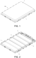
FIG. 1 is a schematic three-dimensional view of a structure of a battery pack according to an embodiment of the disclosure. -
FIG. 2 is a schematic three-dimensional view of structures of a case and cell assemblies according to an embodiment of the disclosure. -
FIG. 3 is a schematic top view of the structures ofFIG. 2 . -
FIG. 4 is a schematic three-dimensional view of the structure of the case according to an embodiment of the disclosure. -
FIG. 5 is a schematic three-dimensional view of the structure of one cell assembly according to an embodiment of the disclosure. -
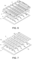
FIG. 6 is a schematic exploded view of the structure of the case according to an embodiment of the disclosure. -
FIG. 7 is a schematic three-dimensional view of structures of a heat exchange plat and a bottom protection plate according to an embodiment of the disclosure. -
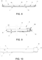
FIG. 8 is a schematic cross-sectional view of the structure taken along A-A inFIG. 3 . -
FIG. 9 is a schematic local enlargement view of the structure inFIG. 8 . -
FIG. 10 is a schematic cross-sectional view of a structure of a discharge through hole according to an embodiment of the disclosure. -
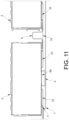
FIG. 11 is a schematic local enlargement view of the structure taken along B-B inFIG. 3 . -
FIG. 12 is a schematic cross-sectional view of a structure of a separating beam according to an embodiment of the disclosure. -
FIG. 13 is a schematic local enlargement view of the structure taken along C-C inFIG. 3 . -
FIG. 14 is a first schematic view of a structure of a reinforcing member according to an embodiment of the disclosure. -
FIG. 15 is a schematic local enlargement view of the structure inFIG. 14 . -
FIG. 16 is a second schematic view of the structure of the reinforcing member according to an embodiment of the disclosure. -
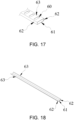
FIG. 17 is a schematic local enlargement view of the structure inFIG. 16 . -
FIG. 18 is a third schematic view of the structure of the reinforcing member according to an embodiment of the disclosure. -
FIG. 19 is a schematic local enlargement view of the structure inFIG. 18 . -
FIG. 20 is a schematic view of a structure of arrangement of mica plates according to an embodiment of the disclosure. - The implementation of the disclosure is illustrated below by specific embodiments. A person having ordinary skill in the art can easily understand other advantages and effects of the disclosure from the content disclosed in this specification.
- It should be noted that the structures, scales, sizes, etc. shown in the accompanying drawings in the specification are only to be used together with the content disclosed in the specification for a person having ordinary skill in the art to comprehend and read, are not intended to define the defining conditions of the implementation of the disclosure, and therefore have no technical significance. Any structural modification, proportional relationship change, or size adjustment, without affecting the effects and objectives that can be achieved by the disclosure, should still fall within the scope of the technical content disclosed in the disclosure. Further, terms such as "upper", "lower", "left", "right", "middle", and "one" quoted in this specification are only for the convenience of description and are not used to define the applicable scope of the disclosure. The change or adjustment of its relative relationship should also be regarded as the applicable scope of the disclosure without substantive change of the technical content.
- With reference to
FIG. 1 to FIG. 20 , this embodiment provides abattery pack 100 including acase 1 andcell assemblies 2 disposed in thecase 1. Thecase 1 includes aheat exchange plate 5 and abottom protection plate 7 disposed below theheat exchange plate 5, and thecell assemblies 2 are disposed on theheat exchange plate 5. - The
heat exchange plate 5 may exchange heat with thecell assemblies 2, so that thecell assemblies 2 are in a suitable temperature range. As such, the working efficiency of thecell assemblies 2 is improved, and the risk of thermal runaway of thecell assemblies 2 is lowered. In some embodiments, theheat exchange plate 5 may be provided with refrigeration structures such as semiconductor refrigeration fins and heating structures such as heating fins, which may directly generate or absorb heat and exchange heat with thecell assemblies 2. In this embodiment, heatexchange flow channels 53 for circulating a heat exchange medium is provided in theheat exchange plate 5. The heat exchange medium flows in the heatexchange flow channels 53 and exchanges heat with thecell assemblies 2 through theheat exchange plate 5. - As shown in
FIG. 5 , onecell assembly 2 includes a plurality ofcells 20, and an explosion-proof valve 4 is provided on a side of each of thecells 20 facing theheat exchange plate 5. In some embodiments, thecells 20 are cylindrical, and the cylindrical cells exhibit the advantages of mature winding technology, high production efficiency, and low costs. In this embodiment, thecells 20 are square, and the square cells exhibit the advantages of simple structures, easy arrangement, and high energy density. - As shown in
FIG. 7 andFIG. 13 , theheat exchange plate 5 is provided with pressure relief throughholes 51 corresponding to the explosion-proof valves 4. When the explosion-proof valves 4 of thecells 20 are opened, high-temperature and high-pressure substances ejected by the explosion-proof valves 4 may enter between theheat exchange plate 5 and thebottom protection plate 7 through the corresponding pressure relief throughholes 51 for pressure relief. In this embodiment, the pressure relief throughholes 51 are arranged to avoid the heatexchange flow channels 53 in theheat exchange plate 5, for example, between adjacent heatexchange flow channels 53, to prevent the heat exchange medium in the heatexchange flow channels 53 from leaking. - As shown in
FIG. 1 andFIG. 5 , in this embodiment, thebattery pack 100 has a height direction, a width direction, and a length direction that are perpendicular to one another. The height direction of thebattery pack 100 is the direction in which the explosion-proof valves 4 on thecells 20 are oriented, that is, the orientation direction of the pressure relief throughholes 51. Dimensions of thebattery pack 100 in the height direction, the width direction, and the length direction are not limited. - As shown in
FIG. 6, FIG. 7 , andFIG. 11 , reinforcingmembers 6 are disposed between theheat exchange plate 5 and thebottom protection plate 7, and each of the reinforcingmembers 6 includes abase portion 61 and supportingportions 62 connected to thebase portion 61. Thebase portion 61 is disposed on thebottom protection plate 7, and the supportingportions 62 are supported between thebottom protection plate 7 and theheat exchange plate 5. In the height direction of thebattery pack 100, projection of the pressure relief throughholes 51 at least partially overlap projection of thebase portions 61. - The reinforcing
members 6 support and strengthen thebottom protection plate 7 and theheat exchange plate 5. After the high-temperature and high-pressure substances enter between theheat exchange plate 5 and thebottom protection plate 7 through the pressure relief throughholes 51, in the height direction of thebattery pack 100, the portions where the projections of thebase portions 61 of the reinforcingmembers 6 overlap the projections of the pressure relief throughholes 51 may block the high-temperature and high-pressure substances. In this way, the corrosion and direct impact of the high-temperature and high-pressure substances on thebottom protection plate 7 is reduced, and the risk of thebottom protection plate 7 being penetrated is also lowered. In this embodiment, in the height direction of thebattery pack 100, the projections of the pressure relief throughholes 51 is entirely within the projection of thebase portion 61. When the high-temperature and high-pressure substances pass through the pressure relief throughholes 51 in the height direction of thebattery pack 100, the high-temperature and high-pressure substances are all ejected on thebase portions 61. When sizes of thebase portions 61 remain unchanged, an effective protection area of thebase portions 61 on thebottom protection plate 7 may be increased, and the protection effect generated by thebase portions 61 on thebottom protection plate 7 may be improved. - The
heat exchange plate 5 and the reinforcingmembers 6 may be connected by laser penetration welding, riveting connection, gluing, etc. The reinforcingmembers 6 may also be connected to thebottom protection plate 7 through various methods such as laser penetration welding, bonding, riveting connection, bolt connection, etc. In this embodiment, as shown inFIG. 6 , mountingbosses 71 protruding toward theheat exchange plate 5 is provided on thebottom protection plate 7 at positions corresponding to the reinforcingmembers 6. Each of the mountingbosses 71 is provided with a bolt hole, and the reinforcingmembers 6 are connected onto the mountingbosses 71 through bolts. The mountingbosses 71 may reduce a matching area between the bottom protection plate and the reinforcingmembers 6, so that the overall processing difficulty of thebottom protection plate 7 is lowered. - In this embodiment, the
cells 20 of thecell assemblies 2 are stacked in sequence in the width direction of thebattery pack 100. Correspondingly, as shown inFIG. 6 and FIG. 7 , the pressure relief throughholes 51 of theheat exchange plate 5 are also arranged in sequence in the width direction of thebattery pack 100. Each of thebase portions 61 is in a long strip shape and extends in the width direction of thebattery pack 100, so that thebase portions 61 may correspond to the pressure relief throughholes 51 in the width direction of thebattery pack 100. - As shown in
FIG. 14 to FIG. 18 , in this embodiment, each of the supportingportions 62 is in a long strip shape extending in the width direction of thebattery pack 100. The supportingportions 62 are disposed on both sides of thebase portion 61 in the length direction of thebattery pack 100, and each of the pressure relief throughholes 51 is disposed between the two supportingportions 62. Since each of the pressure relief throughholes 51 is disposed correspondingly between the two supportingportions 62, the high-temperature and high-pressure substances discharged from the pressure relief throughholes 51 may enter between the two supportingportions 62. The two supportingportions 62 may block the high-temperature and high-pressure substances between the two supportingportions 62 and constrain a discharge trajectory of the high-temperature and high-pressure substances, so that damage to the battery pack structure outside the reinforcingmembers 6 by the high-temperature and high-pressure substances is decreased. - Further, in this embodiment, the
cell assemblies 2 and theheat exchange plate 5 are bonded through structural glue and thermally conductive glue. Gaps between thecell assemblies 2 and theheat exchange plate 5 filled with structural glue and thermal conductive glue is beneficial to blocking the high-temperature and high-pressure substances. In this way, the risk of the high-temperature and high-pressure substances overflowing to other locations in thecase 1 and causing chain thermal runaway of thecells 20 is lowered. - In this embodiment, lifting
portions 63 extending in the width direction of thebattery pack 100 are further disposed on edges of the supportingportions 62 close to the heat exchange plate, and the liftingportions 63 are attached to theheat exchange plate 5. The liftingportion 63 may increase the contact areas between the supportingportions 62 and theheat exchange plate 5, so that the extrusion stress between the supportingportions 62 and theheat exchange plate 5 is reduced, and the strength of theheat exchange plate 5 is improved. - To be specific, as shown in
FIG. 14 to FIG. 17 , in some embodiments, two liftingportions 63 extend toward each other, that is, each of the liftingportions 63 is located between the two supportingportions 62 and is connected to the two supportingportions 62. The liftingportions 63 are provided with receiving throughholes 60 corresponding to the pressure relief throughholes 51. Each liftingportion 63 is located between the two supportingportions 62, so that the folding moment endured by the reinforcingmember 6 may be reduced and the reinforcingmember 6 may be prevented from being deformed. - To be specific, each of the reinforcing
members 6 is a square tube extending in the width direction of thebattery pack 100 in this embodiment. In the height direction of thebattery pack 100, the bottom of the square tube is thebase portion 61, the outer walls on both sides of the bottom are the supportingportions 62, and the top of the square tube is the liftingportion 63. Each receiving throughhole 60 may be sequentially opened on the top of the square tube in the length direction of the square tube through punching or other machine processing methods. The square tube may be purchased directly according to the specifications without mold re-opening and processing, so that the production costs of the reinforcingmembers 6 are reduced. - As shown in
FIG. 14 andFIG. 15 , in some embodiments, the number of the receiving throughholes 60 is less than the number of the pressure relief throughholes 51, and one of the receiving throughholes 60 is disposed corresponding to plural pressure relief throughholes 51. The arrangement of one receiving throughhole 60 corresponding to multiple pressure relief throughholes 51 may allow the number of the receiving throughholes 60 to be reduced and the processing costs to be lowered. - As shown in
FIG. 16 andFIG. 17 , in other embodiments, the number of the receiving throughholes 60 may also correspond to the number of the pressure relief throughholes 51, and the receiving throughholes 60 and the pressure relief throughholes 51 are arranged in one-to-one. Compared to the arrangement one receiving throughhole 60 corresponding to multiple pressure relief throughholes 51, the one-to-one arrangement of the receiving throughholes 60 and the pressure relief throughholes 51 makes the contact area between the reinforcingmembers 6 and theheat exchange plate 5 larger. In this way, the lifting effect of lifting theheat exchange plate 5 is improved and stress concentration is reduced. - As shown in
FIG. 18 to FIG. 20 , in some embodiments, the two liftingportions 63 extend away from each other, that is, each of the two supportingportions 62 is provided with the liftingportion 63. The liftingportion 63 is located on a side of the corresponding supportingportion 62 away from the other supportingportion 62. To be specific, the liftingportion 63 is a flange formed by the edge of the supportingportion 62 close to theheat exchange plate 5 being folded and extending toward the outside of the supportingportion 62. Thebase portion 61, the supportingportions 62, and the liftingportions 63 of each reinforcingmember 6 may all be formed from plate materials through a stamping process. The stamping processing is a simple process and has the advantages of low costs and high processing efficiency. In this embodiment, an included angle between thebase portion 61 and each of the supportingportions 62 is an obtuse angle, so that the space between the two supportingportions 62 is increased, and the high-temperature and high-pressure substances may be quickly discharged from the reinforcingmembers 6. - As shown in
FIG. 2 to FIG. 7 , in this embodiment,plurality cell assemblies 2 are provided in thecase 1, and thecell assemblies 2 are disposed side by side in sequence in the length direction of thebattery pack 100 on theheat exchange plate 5. Plural reinforcingmembers 6 are provided, and the reinforcingmembers 6 are disposed side by side corresponding to thecell assemblies 2. Increasing the number of thecell assemblies 2 may increase the total energy storage capacity of the battery pack. Increasing the number of the reinforcingmembers 6 may improve the structural strength of theheat exchange plate 5 and thebottom protection plate 7. Further, the reinforcingmembers 6 are arranged corresponding to thecell assemblies 2, so that the extrusion stress of thecell assemblies 2 on theheat exchange plate 5 is relieved, and theheat exchange plate 5 is better supported. - As shown in
FIG. 3 to FIG. 11 , in this embodiment, separatingbeams 9 extending in the width direction of thebattery pack 100 is provided on a side of theheat exchange plate 5 away from thebottom protection plate 7, and each of the separating beams 9 is located between the twoadjacent cell assemblies 2. In this embodiment, separatingbeams 9 are provided between adjacentbattery cell assemblies 2 in the length direction of thebattery pack 100. The separating beams 9 may support an outer wall of thecase 1 in the width direction of thebattery pack 100 and improve the structural strength of thecase 1. Further, each of the separating beams may separate thecell assemblies 2 on both sides of the separating beams 9. When thecells 20 in onecell assembly 2 on one side of theseparation beam 9 are thermally runaway, theseparation beam 9 may block the high-temperature and high-pressure substances and reduce the impact of the thermallyrunaway cell assembly 2 on theadjacent cell assembly 2. - As shown in
FIG. 8 to FIG. 10 , in this embodiment, both ends of each of the separatingbeams 9 are connected to an inner wall of thecase 1, and a discharge throughhole 12 is provided on an outer wall of thecase 1 corresponding to an end portion of theseparating beam 9. Adischarge channel 8 communicating with the discharge throughhole 12 is provided in theseparating beam 9, and a communicating throughhole 52 communicating with thedischarge channel 8 is provided on theheat exchange plate 5 corresponding to theseparating beam 9. Theheat exchange plate 5 and thebottom protection plate 7 communicate with the discharge throughhole 12 through the communicating throughhole 52 and thedischarge channel 8. - After the thermal runaway of the
cells 20, the high-temperature and high-pressure substances discharged between theheat exchange plate 5 and thebottom protection plate 7 may enter thedischarge channel 8 through the communicating throughhole 52 and then are discharged out of thebattery pack 100 through thedischarge channel 8 and the discharge throughhole 12. Thedischarge channel 8 is arranged in theseparating beam 9, so no additional arrangement space is required, so that a volume of thebattery pack 100 is reduced and the energy density of thebattery pack 100 is increased. - In order to reduce the volume of the
battery pack 100 and increase the energy density of thebattery pack 100, the size between theheat exchange plate 5 and thebottom protection plate 7 in the height direction of thebattery pack 100 is usually relatively narrow. The size of the outer wall of thecase 1 corresponding to the height direction of thebattery pack 100 between theheat exchange plate 5 and thebottom protection plate 7 is correspondingly narrow, making it difficult to arrange the discharge throughhole 12. In this embodiment, theseparating beam 9 is provided on the side of theheat exchange plate 5 away from thebottom protection plate 7, so that the outer wall of thecase 1 has a sufficient arrangement space on the side of theheat exchange plate 5 away from thebottom protection plate 7 in the height direction of thebattery pack 100. The discharge throughhole 12 is arranged on the outer wall of thecase 1 corresponding to the end portion of theseparating beam 9 on the side of theheat exchange plate 5 away from thebottom protection plate 7. In this way, the arrangement space of the discharge throughhole 12 may be increased, the size of the discharge throughhole 12 in the height direction of thebattery pack 100 is increased, and the discharge efficiency of the high-temperature and high-pressure substances is further improved. - As shown in
FIG. 6 andFIG. 8 to FIG. 10 , in this embodiment, the outer wall of thecase 1 is aside beam 10 with a tubular structure formed by rolling and processing of high-strength steel. The tubular structure exhibits the advantages of high strength and light weight, so that the overall structural strength of thecase 1 may be improved. The end portion of theseparating beam 9 communicates with the inside of theside beam 10. The discharge throughhole 12 is opened on the side of theside beam 10 close to the outside of thecase 1, and thedischarge channel 8 in theseparating beam 9 communicates with the discharge throughhole 12 through theside beam 10. - To be specific, as shown in
FIG. 6 ,FIG. 11 , andFIG. 12 , in this embodiment, theseparating beam 9 includes atop portion 91 extending in the width direction of thebattery pack 100. The top portion is located above theheat exchange plate 5 and twoside portions 92 are provided on both sides of the top portion toward theheat exchange plate 5. The side portions are connected to theheat exchange plate 5 and are enclosed with theheat exchange plate 5 and the top portion to form thedischarge channel 8. In this embodiment, the edge of each of theside portions 92 is also provided with a flange to be attached to theheat exchange plate 5, so as to facilitate the attachment of theseparating beam 9 and theheat exchange plate 5. Thetop portion 91, theside portions 92, and the flanges of theseparating beam 9 may be integrally stamped and formed from plates, which has a simple process and requires low costs. Theside portions 92 of theseparating beam 9 are connected onto theheat exchange plate 5. Theside portions 92, thetop portion 91, and theheat exchange plate 5 are closed to form thedischarge channel 8, so that there is no need to provide additional structures to form thedischarge channel 8, which can make thebattery pack 100 lighter and reduce the material costs. - As shown in
FIG. 1 to FIG. 10 , in this embodiment, the discharge throughholes 12 are provided with waterproof andbreathable valves 11. The waterproof andbreathable valves 11 open when the high-temperature and high-pressure gas is discharged, so that the high-temperature and high-pressure substances in thecase 1 may be discharged in time. The waterproof andbreathable valves 11 are closed before the high-temperature and high-pressure gas is discharged, is breathable, and may prevent dust and other impurities outside thecase 1 from entering thecase 1 while balancing the pressure inside and outside thecase 1, so that the service life of thebattery pack 100 is thereby increased. - In some embodiments, a
protection layer 64 is provided on a side of thebase portion 61 of the reinforcingmember 6 facing the pressure relief throughhole 51. In some other embodiments, theprotection layer 64 is also provided on sides of the supportingportions 62 of the reinforcingmember 6 close to thebase portion 61. Providing theprotection layer 64 partially on the reinforcingmember 6 may reduce the arrangement area of theprotection layer 64 and reduce a weight and material costs of thebattery pack 100. - As shown in
FIG. 18 to FIG. 20 , in this embodiment, theprotection layer 64 is provided on the side of thebase portion 61 of the reinforcingmember 6 facing the pressure relief throughhole 51 and the sides of the supportingportions 62 close to thebase portion 61. In this way, the protection range of theprotection layer 64 is increased, and the protective effect on the reinforcingmember 6 is improved. Theprotection layer 64 may reduce the impact, corrosion, or burning of the reinforcingmembers 6 caused by the high-temperature and high-pressure gas, so the risk of thebottom protection plate 7 being penetrated by the high-temperature and high-pressure gas is further reduced. - In some embodiments, the
protection layer 64 may be a ceramic, silicate, phosphate, or other coating coated on the reinforcingmembers 6 and has high temperature resistance and certain structural strength, so that theprotection layer 64 may reduce the impact and burning of the reinforcingmember 6 by the high-temperature and high-pressure gas. As shown inFIG. 20 , in this embodiment, theprotection layer 64 is made ofmica plates 65. Themica plates 65 may be fixed on the reinforcingmembers 6 through bonding, bolting, etc., and exhibit the advantages of light weight, good high temperature resistance and insulation performance, and high cost performance. - In this embodiment, the
bottom protection plate 7 may be made of aluminum, a composite material, a steel plate, and other materials, and the reinforcingmembers 6 may be made of aluminum or stainless steel. Aluminum is light in weight, which is beneficial to reducing the weight of the battery pack and improving the energy density of the battery pack. Stainless steel has good corrosion resistance and high strength, which is beneficial to improving the structural strength between theheat exchange plate 5 and thebottom protection plate 7. - In view of the foregoing, in the battery pack provided by the disclosure, the
cell assemblies 2 are disposed on theheat exchange plate 5, and each of thecell assemblies 2 includesplural cells 20. The explosion-proof valves 4 of thecells 20 are all disposed on the sides of thecells 20 facing theheat exchange plate 5, and theheat exchange plate 5 is provided with the pressure relief throughholes 51 corresponding to the explosion-proof valves 4. In this way, when the explosion-proof valves 4 of thecells 20 are opened, the high-temperature and high-pressure substances ejected by the explosion-proof valves 4 may enter between theheat exchange plate 5 and thebottom protection plate 7 through the corresponding pressure relief throughholes 51 for pressure relief. The reinforcingmembers 6 are disposed between theheat exchange plate 5 and thebottom protection plate 7, and each of the reinforcingmembers 6 includes thebase portion 61 and the supportingportions 62 connected to thebase portion 61. Thebase portions 61 are disposed on thebottom protection plate 7, and the supportingportions 62 are supported between thebottom protection plate 7 and theheat exchange plate 5. In the height direction of the battery pack, the projections of the pressure relief throughholes 51 at least partially overlap the projections of thebase portions 61. Therefore, the reinforcingmembers 6 support and strengthen thebottom protection plate 7 and theheat exchange plate 5. Further, after the high-temperature and high-pressure substances enter between theheat exchange plate 5 and thebottom protection plate 7 through the pressure relief throughholes 51, in the height direction of thebattery pack 100, the portions where the projections of thebase portions 61 of the reinforcingmembers 6 overlap the projections of the pressure relief throughholes 51 may block the high-temperature and high-pressure substances. In this way, the direct impact and corrosion of the high-temperature and high-pressure substances on thebottom protection plate 7 is reduced, and the risk of thebottom protection plate 7 being penetrated is also lowered.
Claims (15)
- A battery pack (100), characterized by comprising a case (1) and cell assemblies (2) disposed in the case (1), wherein the case (1) comprises a heat exchange plate (5) and a bottom protection plate (7) disposed below the heat exchange plate (5), and the cell assemblies (2) are disposed on the heat exchange plate (5),each of the cell assemblies (2) comprises a plurality of cells (20), an explosion-proof valve (4) is provided on a side of each of the cells (20) facing the heat exchange plate (5), and the heat exchange plate (5) is provided with pressure relief through holes (51) corresponding to the explosion-proof valves (4),reinforcing members (6) are disposed between the heat exchange plate (5) and the bottom protection plate (7), each of the reinforcing members (6) comprises a base portion (61) and supporting portions (62) connected to the base portion (61), the base portion (61) is disposed on the bottom protection plate (7), the supporting portions (62) are supported between the bottom protection plate (7) and the heat exchange plate (5), and in a height direction of the battery pack (100), projection of the pressure relief through holes (51) at least partially overlap projection of the base portions (61).
- The battery pack (100) according to claim 1, characterized in that the pressure relief through holes (51) are arranged in sequence in a width direction of the battery pack (100), and each of the base portions (61) is in a long strip shape and extends in the width direction of the battery pack (100).
- The battery pack (100) according to claim 2, characterized in that each of the supporting portions (62) is in a long strip shape extending in the width direction of the battery pack (100), the supporting portions (62) are provided on both sides of the base portion (61) in a length direction of the battery pack (100), and each of the pressure relief through holes (51) is disposed between the two supporting portions (62).
- The battery pack (100) according to claim 3, characterized in that lifting portions (63) extending in the width direction of the battery pack (100) are further provided on edges of the supporting portions (62) close to the heat exchange plate (5), and the lifting portions (63) are attached to the heat exchange plate (5).
- The battery pack (100) according to claim 4, characterized in that the two supporting portions (62) are provided with the lifting portions (63), and the two lifting portions (63) extend away from each other.
- The battery pack (100) according to claim 5, characterized in that an included angle between the base portion (61) and each of the supporting portions (62) is an obtuse angle.
- The battery pack (100) according to claim 4, characterized in that the two lifting portions (63) extend toward each other, and the lifting portions (63) are provided with receiving through holes (60) corresponding to the pressure relief through holes (51).
- The battery pack (100) according to claim 7, characterized in that a number of the receiving through holes (60) is less than a number of the pressure relief through holes and one of the receiving through holes (60) is disposed corresponding to plural of the pressure relief through holes (51), or the number of the receiving through holes (60) corresponds to the number of the pressure relief through holes (51), and the receiving through holes (60) and the pressure relief through holes (51) are arranged in one-to-one.
- The battery pack (100) according to any one of claims 1-8, characterized in that plural cell assemblies (2) are provided, the cell assemblies (2) are disposed side by side in sequence in a length direction of the battery pack (100) on the heat exchange plate (5), plural reinforcing members (6) are provided, and the reinforcing members (6) are disposed side by side corresponding to the cell assemblies (2).
- The battery pack (100) according to claim 9, characterized in that separating beams (9) extending in a width direction of the battery pack (100) are provided on a side of the heat exchange plate (5) away from the bottom protection plate (7), and each of the separating beams (9) is located between the two cell assemblies (2) adjacent to each other.
- The battery pack (100) according to claim 10, characterized in that both ends of each of the separating beams (9) are connected to an inner wall of the case (1), a discharge through hole (12) is provided on an outer wall of the case (1) corresponding to an end portion of the separating beam (9), a discharge channel (8) communicating with the discharge through hole (12) is provided in the separating beam (9), a communicating through hole (52) communicating with the discharge channel (8) is provided on the heat exchange plate (5) corresponding to the separating beam (9), and the heat exchange plate (5) and the bottom protection plate (7) communicate with the discharge through hole (12) through the communicating through hole (52) and the discharge channel (8).
- The battery pack (100) according to claim 11, characterized in that each of the separating beams (9) comprises a top portion (91) extending in the width direction of the battery pack (100), the top portion (91) is located above the heat exchange plate (5), two side portions (92) are provided on both sides of the top portion (91) toward the heat exchange plate (5), and the side portions (92) are connected onto the heat exchange plate (5) and are enclosed with the heat exchange plate (5) and the top portion (91) to form the discharge channel (8).
- The battery pack (100) according to claim 11, characterized in that the discharge through holes (12) are provided with waterproof and breathable valves (11).
- The battery pack (100) according to any one of claims 1-8, characterized in that in the height direction of the battery pack (100), the projection of the pressure relief through holes (51) are within the projection of the base portions (61).
- The battery pack (100) according to any one of claims 1-8, characterized in that a protection layer (64) is provided on at least one of a side of the base portion (61) facing the pressure relief through hole (51) and a side of the supporting portion (62) close to the base portion (61).
Applications Claiming Priority (1)
| Application Number | Priority Date | Filing Date | Title |
|---|---|---|---|
| CN202322293241.7U CN221239698U (en) | 2023-08-24 | 2023-08-24 | Battery pack |
Publications (2)
| Publication Number | Publication Date |
|---|---|
| EP4513621A1 true EP4513621A1 (en) | 2025-02-26 |
| EP4513621A8 EP4513621A8 (en) | 2025-04-16 |
Family
ID=89223937
Family Applications (1)
| Application Number | Title | Priority Date | Filing Date |
|---|---|---|---|
| EP23217213.0A Pending EP4513621A1 (en) | 2023-08-24 | 2023-12-15 | Battery pack |
Country Status (4)
| Country | Link |
|---|---|
| US (1) | US20250070352A1 (en) |
| EP (1) | EP4513621A1 (en) |
| JP (1) | JP7681674B2 (en) |
| CN (1) | CN221239698U (en) |
Families Citing this family (2)
| Publication number | Priority date | Publication date | Assignee | Title |
|---|---|---|---|---|
| KR102883559B1 (en) * | 2021-04-13 | 2025-11-10 | 주식회사 엘지에너지솔루션 | Battery pack |
| CN121216015B (en) * | 2025-11-21 | 2026-05-12 | 宁德时代新能源科技股份有限公司 | Battery device and electricity utilization device |
Citations (8)
| Publication number | Priority date | Publication date | Assignee | Title |
|---|---|---|---|---|
| US20190229384A1 (en) * | 2018-01-19 | 2019-07-25 | Hanon Systems | Battery cooling plate with integrated air vents |
| DE102019211528A1 (en) * | 2019-08-01 | 2021-02-04 | Audi Ag | Battery housing for at least one battery cell with a ceramic or glass-like or metallic protective coating, as well as a motor vehicle |
| CN112490579A (en) * | 2020-12-16 | 2021-03-12 | 广东和胜新能源汽车配件有限公司 | Battery box |
| US20220013853A1 (en) * | 2020-07-10 | 2022-01-13 | Contemporary Amperex Technology Co., Limited | Battery, power consumption device, method and device for preparing a battery |
| EP4064436A1 (en) * | 2020-09-30 | 2022-09-28 | Contemporary Amperex Technology Co., Limited | Battery, device, and production method and apparatus for battery |
| US20230012679A1 (en) * | 2019-12-03 | 2023-01-19 | Saic Motor Corporation Limited | Battery assembly, battery module and battery energy storage device |
| DE102021124832A1 (en) * | 2021-09-27 | 2023-04-13 | Audi Aktiengesellschaft | Battery arrangement of a drive battery for a motor vehicle and motor vehicle with a battery arrangement |
| WO2023083276A1 (en) * | 2021-11-12 | 2023-05-19 | 长城汽车股份有限公司 | Vehicle |
Family Cites Families (10)
| Publication number | Priority date | Publication date | Assignee | Title |
|---|---|---|---|---|
| WO2022006896A1 (en) | 2020-07-10 | 2022-01-13 | 宁德时代新能源科技股份有限公司 | Battery and related apparatus thereof, preparation method therefor, and preparation device therefor |
| EP3965197B1 (en) | 2020-07-10 | 2023-03-15 | Contemporary Amperex Technology Co., Limited | Battery, electric device, and battery preparation method and device |
| JP7549733B2 (en) | 2020-10-19 | 2024-09-11 | ジアンス・コンテンポラリー・アンプレックス・テクノロジー・リミテッド | Battery, power receiving device, and method and equipment for manufacturing the battery |
| JP7445001B2 (en) | 2021-03-26 | 2024-03-06 | 江▲蘇▼▲時▼代新能源科技有限公司 | Battery cells, batteries, power consumption devices, manufacturing methods and manufacturing equipment |
| PL4207459T3 (en) | 2021-09-29 | 2026-05-11 | Contemporary Amperex Technology (Hong Kong) Limited | Pressure relief mechanism, battery cell, battery, electrical device, and pressure relief mechanism manufacturing method |
| EP4235922A4 (en) | 2022-01-12 | 2024-04-17 | Contemporary Amperex Technology Co., Limited | BOX FOR BATTERY, BATTERY, POWER CONSUMPTION DEVICE AND METHOD AND DEVICE FOR PRODUCING A BOX |
| JP7525627B2 (en) | 2022-01-21 | 2024-07-30 | 寧徳時代新能源科技股▲分▼有限公司 | Energy Storage Systems |
| CN217788585U (en) | 2022-08-29 | 2022-11-11 | 宁德时代新能源科技股份有限公司 | End cover components, battery cells, batteries and electrical equipment |
| WO2024092442A1 (en) | 2022-10-31 | 2024-05-10 | 宁德时代新能源科技股份有限公司 | Battery and electric device |
| CN219476914U (en) | 2023-01-13 | 2023-08-04 | 宁德时代新能源科技股份有限公司 | Battery monomer, battery and electric equipment |
-
2023
- 2023-08-24 CN CN202322293241.7U patent/CN221239698U/en active Active
- 2023-12-13 JP JP2023209920A patent/JP7681674B2/en active Active
- 2023-12-13 US US18/539,184 patent/US20250070352A1/en active Pending
- 2023-12-15 EP EP23217213.0A patent/EP4513621A1/en active Pending
Patent Citations (8)
| Publication number | Priority date | Publication date | Assignee | Title |
|---|---|---|---|---|
| US20190229384A1 (en) * | 2018-01-19 | 2019-07-25 | Hanon Systems | Battery cooling plate with integrated air vents |
| DE102019211528A1 (en) * | 2019-08-01 | 2021-02-04 | Audi Ag | Battery housing for at least one battery cell with a ceramic or glass-like or metallic protective coating, as well as a motor vehicle |
| US20230012679A1 (en) * | 2019-12-03 | 2023-01-19 | Saic Motor Corporation Limited | Battery assembly, battery module and battery energy storage device |
| US20220013853A1 (en) * | 2020-07-10 | 2022-01-13 | Contemporary Amperex Technology Co., Limited | Battery, power consumption device, method and device for preparing a battery |
| EP4064436A1 (en) * | 2020-09-30 | 2022-09-28 | Contemporary Amperex Technology Co., Limited | Battery, device, and production method and apparatus for battery |
| CN112490579A (en) * | 2020-12-16 | 2021-03-12 | 广东和胜新能源汽车配件有限公司 | Battery box |
| DE102021124832A1 (en) * | 2021-09-27 | 2023-04-13 | Audi Aktiengesellschaft | Battery arrangement of a drive battery for a motor vehicle and motor vehicle with a battery arrangement |
| WO2023083276A1 (en) * | 2021-11-12 | 2023-05-19 | 长城汽车股份有限公司 | Vehicle |
Also Published As
| Publication number | Publication date |
|---|---|
| JP7681674B2 (en) | 2025-05-22 |
| EP4513621A8 (en) | 2025-04-16 |
| JP2025031456A (en) | 2025-03-07 |
| US20250070352A1 (en) | 2025-02-27 |
| CN221239698U (en) | 2024-06-28 |
Similar Documents
| Publication | Publication Date | Title |
|---|---|---|
| US20250070352A1 (en) | Battery pack | |
| US12537254B2 (en) | Battery pack, vehicle, and energy storage device | |
| KR102729242B1 (en) | Power battery packs, energy storage devices and electric vehicles | |
| CN109742281B (en) | a battery box | |
| EP3905374B1 (en) | Battery pack box and battery pack | |
| EP2608310B1 (en) | Battery module with compact structure and excellent heat radiation characteristics, and medium- or large-sized battery pack | |
| CN111446397A (en) | Battery pack box and battery pack | |
| CN212485434U (en) | A battery pack case and battery pack | |
| KR20210133535A (en) | Battery pack and device including the same | |
| CN220628072U (en) | Battery pack | |
| CN219457928U (en) | Battery pack and vehicle including the battery pack | |
| KR20230001963A (en) | Battery pack and device including the same | |
| KR20220040751A (en) | Cooling plate of battery pack | |
| CN111430611B (en) | Battery pack | |
| CN224191163U (en) | High-safety battery pack | |
| WO2025002385A1 (en) | Battery pack | |
| CN210403831U (en) | Battery pack and electric vehicle | |
| CN220544136U (en) | Battery pack trays, battery packs and vehicles | |
| CN220420672U (en) | Battery pack and vehicle with same | |
| CN219937215U (en) | Battery modules and battery packs | |
| CN209658277U (en) | battery module | |
| CN115241574A (en) | An active reinforced heat dissipation structure for small power battery pack and electric vehicle | |
| EP4372891A1 (en) | Battery device and preparation method therefor | |
| EP4715989A1 (en) | Protective plate, housing, and battery pack | |
| CN120810165A (en) | Explosion-proof valve, battery case and battery pack |
Legal Events
| Date | Code | Title | Description |
|---|---|---|---|
| PUAI | Public reference made under article 153(3) epc to a published international application that has entered the european phase |
Free format text: ORIGINAL CODE: 0009012 |
|
| STAA | Information on the status of an ep patent application or granted ep patent |
Free format text: STATUS: REQUEST FOR EXAMINATION WAS MADE |
|
| 17P | Request for examination filed |
Effective date: 20231215 |
|
| AK | Designated contracting states |
Kind code of ref document: A1 Designated state(s): AL AT BE BG CH CY CZ DE DK EE ES FI FR GB GR HR HU IE IS IT LI LT LU LV MC ME MK MT NL NO PL PT RO RS SE SI SK SM TR |