EP4513618A1 - Ccs assembly and battery module - Google Patents
Ccs assembly and battery module Download PDFInfo
- Publication number
- EP4513618A1 EP4513618A1 EP24150008.1A EP24150008A EP4513618A1 EP 4513618 A1 EP4513618 A1 EP 4513618A1 EP 24150008 A EP24150008 A EP 24150008A EP 4513618 A1 EP4513618 A1 EP 4513618A1
- Authority
- EP
- European Patent Office
- Prior art keywords
- groove
- ccs
- battery group
- plastic bracket
- protrusion
- Prior art date
- Legal status (The legal status is an assumption and is not a legal conclusion. Google has not performed a legal analysis and makes no representation as to the accuracy of the status listed.)
- Pending
Links
- 238000005538 encapsulation Methods 0.000 claims abstract description 41
- 239000012790 adhesive layer Substances 0.000 claims description 14
- 239000010410 layer Substances 0.000 claims description 11
- 239000000853 adhesive Substances 0.000 description 18
- 230000001070 adhesive effect Effects 0.000 description 18
- 230000009191 jumping Effects 0.000 description 2
- 230000032683 aging Effects 0.000 description 1
- 239000006260 foam Substances 0.000 description 1
- 239000011810 insulating material Substances 0.000 description 1
- 238000004519 manufacturing process Methods 0.000 description 1
- XLYOFNOQVPJJNP-UHFFFAOYSA-N water Substances O XLYOFNOQVPJJNP-UHFFFAOYSA-N 0.000 description 1
Images




Classifications
-
- H—ELECTRICITY
- H01—ELECTRIC ELEMENTS
- H01M—PROCESSES OR MEANS, e.g. BATTERIES, FOR THE DIRECT CONVERSION OF CHEMICAL ENERGY INTO ELECTRICAL ENERGY
- H01M10/00—Secondary cells; Manufacture thereof
- H01M10/42—Methods or arrangements for servicing or maintenance of secondary cells or secondary half-cells
- H01M10/48—Accumulators combined with arrangements for measuring, testing or indicating the condition of cells, e.g. the level or density of the electrolyte
- H01M10/482—Accumulators combined with arrangements for measuring, testing or indicating the condition of cells, e.g. the level or density of the electrolyte for several batteries or cells simultaneously or sequentially
-
- H—ELECTRICITY
- H01—ELECTRIC ELEMENTS
- H01M—PROCESSES OR MEANS, e.g. BATTERIES, FOR THE DIRECT CONVERSION OF CHEMICAL ENERGY INTO ELECTRICAL ENERGY
- H01M10/00—Secondary cells; Manufacture thereof
- H01M10/42—Methods or arrangements for servicing or maintenance of secondary cells or secondary half-cells
- H01M10/48—Accumulators combined with arrangements for measuring, testing or indicating the condition of cells, e.g. the level or density of the electrolyte
- H01M10/486—Accumulators combined with arrangements for measuring, testing or indicating the condition of cells, e.g. the level or density of the electrolyte for measuring temperature
-
- H—ELECTRICITY
- H01—ELECTRIC ELEMENTS
- H01M—PROCESSES OR MEANS, e.g. BATTERIES, FOR THE DIRECT CONVERSION OF CHEMICAL ENERGY INTO ELECTRICAL ENERGY
- H01M50/00—Constructional details or processes of manufacture of the non-active parts of electrochemical cells other than fuel cells, e.g. hybrid cells
- H01M50/20—Mountings; Secondary casings or frames; Racks, modules or packs; Suspension devices; Shock absorbers; Transport or carrying devices; Holders
- H01M50/204—Racks, modules or packs for multiple batteries or multiple cells
- H01M50/207—Racks, modules or packs for multiple batteries or multiple cells characterised by their shape
- H01M50/209—Racks, modules or packs for multiple batteries or multiple cells characterised by their shape adapted for prismatic or rectangular cells
-
- H—ELECTRICITY
- H01—ELECTRIC ELEMENTS
- H01M—PROCESSES OR MEANS, e.g. BATTERIES, FOR THE DIRECT CONVERSION OF CHEMICAL ENERGY INTO ELECTRICAL ENERGY
- H01M50/00—Constructional details or processes of manufacture of the non-active parts of electrochemical cells other than fuel cells, e.g. hybrid cells
- H01M50/20—Mountings; Secondary casings or frames; Racks, modules or packs; Suspension devices; Shock absorbers; Transport or carrying devices; Holders
- H01M50/204—Racks, modules or packs for multiple batteries or multiple cells
- H01M50/207—Racks, modules or packs for multiple batteries or multiple cells characterised by their shape
- H01M50/213—Racks, modules or packs for multiple batteries or multiple cells characterised by their shape adapted for cells having curved cross-section, e.g. round or elliptic
-
- H—ELECTRICITY
- H01—ELECTRIC ELEMENTS
- H01M—PROCESSES OR MEANS, e.g. BATTERIES, FOR THE DIRECT CONVERSION OF CHEMICAL ENERGY INTO ELECTRICAL ENERGY
- H01M50/00—Constructional details or processes of manufacture of the non-active parts of electrochemical cells other than fuel cells, e.g. hybrid cells
- H01M50/20—Mountings; Secondary casings or frames; Racks, modules or packs; Suspension devices; Shock absorbers; Transport or carrying devices; Holders
- H01M50/296—Mountings; Secondary casings or frames; Racks, modules or packs; Suspension devices; Shock absorbers; Transport or carrying devices; Holders characterised by terminals of battery packs
-
- H—ELECTRICITY
- H01—ELECTRIC ELEMENTS
- H01M—PROCESSES OR MEANS, e.g. BATTERIES, FOR THE DIRECT CONVERSION OF CHEMICAL ENERGY INTO ELECTRICAL ENERGY
- H01M2220/00—Batteries for particular applications
- H01M2220/20—Batteries in motive systems, e.g. vehicle, ship, plane
-
- Y—GENERAL TAGGING OF NEW TECHNOLOGICAL DEVELOPMENTS; GENERAL TAGGING OF CROSS-SECTIONAL TECHNOLOGIES SPANNING OVER SEVERAL SECTIONS OF THE IPC; TECHNICAL SUBJECTS COVERED BY FORMER USPC CROSS-REFERENCE ART COLLECTIONS [XRACs] AND DIGESTS
- Y02—TECHNOLOGIES OR APPLICATIONS FOR MITIGATION OR ADAPTATION AGAINST CLIMATE CHANGE
- Y02E—REDUCTION OF GREENHOUSE GAS [GHG] EMISSIONS, RELATED TO ENERGY GENERATION, TRANSMISSION OR DISTRIBUTION
- Y02E60/00—Enabling technologies; Technologies with a potential or indirect contribution to GHG emissions mitigation
- Y02E60/10—Energy storage using batteries
Definitions
- the present disclosure relates to the field of batteries, and in particular to a CCS assembly and a battery module.
- a battery In a power battery, a battery is electrically connected to a cells contact system (CCS) assembly to allow a battery management system (BMS) to transmit electrical signals.
- the CCS assembly is mounted on a top of a battery group.
- the CCS assembly generally includes a plastic bracket, a flexible circuit board (FPC), a temperature obtaining member, an electrical-signal obtaining member, and a connection bar.
- the temperature obtaining member is configured to collect a temperature of the battery group while in use, and the temperature is transmitted to the BMS through the FPC, such that a usage state of the battery is monitored.
- the temperature obtaining member in the art While the temperature obtaining member in the art is being mounted with the plastic bracket, the temperature obtaining member is directly fixed to the plastic bracket by back adhesive. Since the temperature obtaining member has a water-droplet shape, an outer surface of the temperature obtaining member is curved, a contact area between the temperature obtaining member and the plastic bracket is small. In this case, the temperature obtaining member may be easily detached from the plastic bracket.
- the present disclosure provides a cells contact system (CCS) assembly and a battery module.
- CCS cells contact system
- the present disclosure provides a cells contact system (CCS) assembly, arranged on a top of a battery group.
- the CCS assembly includes: a plastic bracket, defining a through groove; a temperature obtaining member, received in the through groove and comprising a temperature sensor and an encapsulation member sleeving an outside of the temperature sensor, wherein the temperature sensor is configured to obtain a temperature of the battery group, the encapsulation member has a connecting surface connected to the plastic bracket; a connection portion, configured to connect the connecting surface to the plastic bracket and abutting against the temperature obtaining member, wherein the plastic bracket and the connection portion cooperatively prevents the temperature obtaining member from detaching from the plastic bracket in an axial direction of the battery group.
- a pressing block is arranged on at least one side groove wall of the through groove, a protrusion is arranged on at least one side wall of the encapsulation member, the protrusion has the connecting surface, the protrusion is disposed below the pressing block along the axial direction of the battery group, the connection portion connects the protrusion to the pressing block.
- the at least one side groove wall of the through groove comprises two side groove walls, the pressing block is arranged on one of the two side groove walls, a guide is arranged on the other one of the two side groove walls;
- the at least one side wall of the encapsulation member comprises two side walls, the protrusion is arranged on one of the two side walls, a slide groove is defined in the other one of the two side walls; the guide is slidably connected with the slide groove.
- a side of the guide facing towards an inlet of the through groove has a notch, a length of the guide is less than a length of the slide groove.
- a length of the pressing block is less than a length of the protrusion along a direction of the temperature obtaining member being mounted.
- the pressing block is disposed at a middle of the through groove along the direction of the temperature obtaining member being mounted.
- a bottom wall of the protrusion and a bottom wall of the encapsulation member are co-planar.
- each of two opposite side walls of the encapsulation member is spaced apart from a corresponding groove wall of the through groove.
- connection portion comprises a compressible layer and two adhesive layers respectively disposed on two opposite sides of the compressible layer.
- One of the two adhesive layers is connected to the connecting surface, and the other one of the two adhesive layers is connected to the plastic bracket.
- the present disclosure provides a battery module, including: a battery group, and the cells contact system (CCS) assembly as described in the above.
- the CCS assembly is arranged on a top of the battery group.
- the present embodiment provides a cells contact system (CCS) assembly 100.
- the CCS assembly 100 is disposed on a top of a battery group and includes a plastic bracket 10, a temperature obtaining member 20, and a connection portion 30 (as shown in FIG. 4 ).
- the plastic bracket 10 is defines a through groove 11.
- the temperature obtaining member 20 is received in the through groove 11.
- the temperature obtaining member 20 includes a temperature sensor 22 and an encapsulation member 21 that sleeves an outside of the temperature sensor 22.
- the temperature sensor 22 is configured to collect a temperature of the battery group.
- the encapsulation member 21 has a connecting surface 213 connected to the plastic bracket 10.
- the connection portion 30 is configured to connect the connecting surface 213 with the plastic bracket 10, such that the plastic bracket 10 prevents the temperature obtaining member 20 from detaching from the plastic bracket 10 in an axial direction of the battery group.
- the plastic bracket 10 defines the through groove 11, the encapsulation member 21 sleeves the outside of the temperature sensor 22 to form the temperature obtaining member 20, and the encapsulation member 21 has the connecting surface 213 connected to the plastic bracket 10. While the temperature obtaining member 20 is being mounted with the plastic bracket 10, the connection portion 30 is disposed and connected between the connecting surface 213 and the plastic bracket 10, such that a contact area between the encapsulation member 21 and the plastic bracket 10 is larger, and that is, a larger connection area is achieved. In this way, connection between the temperature obtaining member 20 and the plastic bracket 10 is more stable. In addition, the plastic bracket 10 prevents the temperature obtaining member 20 from being detached along the axial direction of the battery group, such that the temperature sensor 22 is prevented from detaching from the plastic bracket 10, and therefore, the temperature detected by the temperature sensor 22 may not be jumping abnormally.
- connection portion 30 of the present embodiment is a structural adhesive.
- the structural adhesive is filled into the CCS assembly 100.
- the structural adhesive may flow to reach a space between the encapsulation member 21 and the plastic bracket.
- the structural adhesive solidifies, the structural adhesive is disposed and connects between the encapsulation member 21 and the plastic bracket 10.
- the structural adhesive may further penetrate to reach a space between the CCS assembly 100 and the top of the battery. In this way, the structural adhesive allows the CCS assembly 100 to be connected to the battery group to form a one-piece and integral structure. Therefore, a position of the temperature obtaining member 20 is fixed, and the temperature obtaining member 20 is avoided from sliding relative to the plastic bracket 10.
- the encapsulation member 21 encapsulates the outside of the temperature sensor 22, the temperature sensor 22 is isolated and protected from water.
- the encapsulation member 21 in the present embodiment has a certain thermal conductivity allowing heat generated within the battery group to be transferred to the temperature sensor 22, such that the temperature sensor 22 may monitor the temperature in real time.
- a pressing block 14 is arranged on at least one side groove wall of the through groove 11, and a protrusion 212 is arranged on at least one side wall of the encapsulation member 21.
- the protrusion 212 has the connecting surface 213.
- the protrusion 212 is located below the pressing block 14.
- the protrusion 212 is received in the through groove 11 and is located between the pressing block 14 and a bottom wall of the through groove 11.
- the connection portion 30 is configured to connect the protrusion 212 with the pressing block 14.
- the connecting adhesive is formed between the protrusion 212 and the pressing block 14. In this way, limiting the position of the temperature obtaining member 20 is achieved by the protrusion 212 connecting with the pressing block 14.
- the pressing block 14 is arranged on one groove wall of the through groove 11, and a guide 12 is arranged on another groove wall of the through groove 11.
- the protrusion 212 is arranged on one side wall of the encapsulation member 21, and a slide groove 211 is defined in another side wall of the encapsulation member 21.
- the guide 12 is received in the slide groove 211, such that the guide 12 is slidably connected with the slide groove 211.
- An extension direction of the guide 12 is parallel to a plane in which the top (such as a top surface) of the battery group is located. In this way, the temperature obtaining member 20 may be mounted to a predetermined position in the through groove 11 by sliding along the guide 12 due to the slidable connection between the guide 12 and the slide groove 211.
- the guide 12 is arranged on the plastic bracket 10 and the slide groove 211 is defined in the encapsulation member 21, the guide 12 and the slide groove 211 may be formed easily.
- the temperature obtaining member 20 is inserted into the through groove 11, only one side of the temperature obtaining member 20 having the slide groove 211 needs to be aligned with the guide 12, and the other side of the temperature obtaining member 20 is not restricted by the guide 12. In this way, more space is available while the temperature obtaining member 20 is being inserted, such that a mounting efficiency is improved.
- the pressing block 14 may press the protrusion 212 to prevent the temperature obtaining member 20 from moving excessively, such that the temperature collected by the temperature obtaining member 20 may not be affected or jumping.
- the guide 12 may be arranged on the side wall of the encapsulation member 21, and the slide groove 211 may be defined in the groove wall of the through groove 11, according to demands. In this case, the slidable connection between the encapsulation member 21 and the plastic bracket 10 may also be achieved.
- a side of the guide 12 facing towards an inlet of the through groove 11 defines a notch 13, such that a length of the guide 12 is less than a length of the slide groove 211, and therefore, the entire temperature obtaining member 20 may be received in the through groove 11 easily.
- a larger space is available at the inlet of the through groove 11, and the guide 12 may slide to be received into the slide groove 211 of the encapsulation member 21 of the temperature obtaining member 20 easily.
- a length of the pressing block 14 is less than a length of the protrusion 212 along a mounting direction of the temperature obtaining member 20. Due to the smaller length of the pressing block 14, the plastic bracket 10 may be formed easily.
- the pressing block 14 may be located on a top of the protrusion 212, as long as the position of the temperature obtaining member 20 is limited.
- the pressing block 14 of the present embodiment is disposed at a middle portion of the through groove 11. That is, the encapsulation member 21 has a first end portion near the inlet of the through groove 11, a second end portion away from the inlet of the through groove 11, and a middle portion disposed between the first end portion and the second end portion.
- the pressing block 14 is disposed corresponding to the middle portion. In this way, the pressing block 14 may be easily formed on the plastic bracket 10 and may not be obstructed by any other structure of the plastic bracket 10.
- a bottom wall of the protrusion 212 and a bottom wall of the encapsulation member 21 are co-planar.
- the protrusion 212 may be disposed at a middle of the side wall of the encapsulation member 21.
- the structural adhesive may be poured to allow the structural adhesive, the CCS assembly 100, and the battery group to form a one-piece and integral structure.
- a gap 15 is defined between each of two opposite side walls of the encapsulation member 21 and the wall of the through groove 11. Therefore, the structural adhesive, when being poured, may flow into the space between the CCS assembly 100 and the battery group through the gap 15, such that the CCS assembly 100 and the battery group form the one-piece and integral structure.
- FIG. 3 shows a schematic view of the temperature obtaining member of the present embodiment.
- the temperature sensor 22 of the present embodiment is a temperature sensor having a droplet-shaped head, i.e., the outer surface of the temperature sensor 22 is curved.
- the temperature sensor having the droplet-shaped head is encapsulated inside the encapsulation member 21.
- the temperature obtaining member 20 further includes a wire harness 23 connected to the temperature sensor having the droplet-shaped head. A position of the wire harness 23 is limited by a block of the plastic bracket 10.
- the guide 12 is arranged on the plastic bracket 10, and the slide groove 211 is defined in the encapsulation member 21.
- the entire temperature obtaining member 20 may move only along a direction parallel to the plane on which the top of the battery group is located.
- the plastic bracket 10 prevents the temperature obtaining member 20 from being detached along the axial direction of the battery group, such that the temperature sensor 22 is prevented from being detached from the plastic bracket 10, and the temperature detected by the temperature sensor 22 may not jump abnormally.
- the temperature sensor 22 and the plastic bracket 10 are fixed with each other by the back adhesive, an operation of tearing the back adhesive to adhere to the battery group may be avoided.
- a risk of the temperature sensor 22 being detached, due to aging of the back adhesive, from the plastic bracket 10 may be avoided. Furthermore, a risk of the wiring harness 23 connected to the temperature sensor 22 peeling off the adhesive may be avoided. The mounting efficiency may be improved, and labor costs for mounting may be reduced.
- the CCS assembly 100 of the present embodiment is substantially the same as the CCS assembly 100 of the first embodiment. Differences there between include the following.
- the connection portion 30 of the present embodiment includes a compressible layer 31 and two adhesive layers 32 respectively disposed on two opposite sides of the compressible layer 31. One of the two adhesive layers 32 is connected to the connecting surface 213, and the other one of the two adhesive layers 32 is connected to the bracket 10. In this case, the connection portion 30 is directly connected between the encapsulation member 21 and the bracket 10.
- connection portion 30 includes the compressible layer 31 and the compressible layer 31 can be compressed, a thickness of the entire connection portion 30 is greater than a distance between the bracket 10 and the temperature obtaining member 20 while the temperature obtaining member 20 is being mounted with the bracket 10.
- the protrusion 212 has a connecting surface 213 facing the pressing block 14.
- the pressing block 14 has a block connecting surface facing the protrusion 212.
- the entire connection portion 30 is disposed between the the connecting surface 213 of the protrusion 212 and the block connecting surface.
- a first adhesive layer 32 of the connection portion 30 is arranged on the connecting surface 213 of the protrusion 212, and the second adhesive layer 32 is arranged on the block connecting surface.
- the thickness of the entire connection portion 30 refers to a distance from an outer surface of the first adhesive layer 32 to an outer surface of the second adhesive layer 32.
- the distance between the holder 10 and the temperature obtaining member 20 is a distance from the connecting surface 213 of the protrusion 212 to the block connecting surface.
- two protrusions 212 are respectively arranged on two opposite sides of the encapsulation member 21, two pressing blocks 14 are respectively arranged on two opposite side walls of the through groove 11.
- the two protrusions 212 are connected to the two pressing blocks 14 in one-to-one correspondence through the connection portion 30.
- the compressible layer 31 of the present embodiment is a compressible and insulating material, such as foam, sponge, and the like.
- the present embodiment provides a battery module including a battery group 200 and the CCS assembly 100 as described above.
- the CCS assembly 100 is disposed at the top of the battery group 200 along the axial direction of the battery group 200 and is electrically connected to the battery group 200 to collect voltage signals and current signals of the battery group 200.
- the structural adhesive is poured to the CCS assembly 100 to enable the CSS assembly and the battery group to form the one-piece and integral structure.
Landscapes
- Chemical & Material Sciences (AREA)
- Chemical Kinetics & Catalysis (AREA)
- Electrochemistry (AREA)
- General Chemical & Material Sciences (AREA)
- Engineering & Computer Science (AREA)
- Manufacturing & Machinery (AREA)
- Secondary Cells (AREA)
- Battery Mounting, Suspending (AREA)
Abstract
A CCS assembly and a battery module are provided. The CCS assembly is arranged on a top of a battery group (200). The CCS assembly includes: a plastic bracket (10), defining a through groove (11); a temperature obtaining member (20), received in the through groove (11) and comprising a temperature sensor (22) and an encapsulation member (21) sleeving an outside of the temperature sensor, wherein the temperature sensor is configured to obtain a temperature of the battery group, the encapsulation member has a connecting surface (213) connected to the plastic bracket; a connection portion (30), configured to connect the connecting surface to the plastic bracket and abutting against the temperature obtaining member, wherein the plastic bracket and the connection portion cooperatively prevents the temperature obtaining member from detaching from the plastic bracket in an axial direction of the battery group.
Description
- The present disclosure relates to the field of batteries, and in particular to a CCS assembly and a battery module.
- In a power battery, a battery is electrically connected to a cells contact system (CCS) assembly to allow a battery management system (BMS) to transmit electrical signals. The CCS assembly is mounted on a top of a battery group. The CCS assembly generally includes a plastic bracket, a flexible circuit board (FPC), a temperature obtaining member, an electrical-signal obtaining member, and a connection bar. The temperature obtaining member is configured to collect a temperature of the battery group while in use, and the temperature is transmitted to the BMS through the FPC, such that a usage state of the battery is monitored.
- While the temperature obtaining member in the art is being mounted with the plastic bracket, the temperature obtaining member is directly fixed to the plastic bracket by back adhesive. Since the temperature obtaining member has a water-droplet shape, an outer surface of the temperature obtaining member is curved, a contact area between the temperature obtaining member and the plastic bracket is small. In this case, the temperature obtaining member may be easily detached from the plastic bracket.
- The present disclosure provides a cells contact system (CCS) assembly and a battery module.
- In a first aspect, the present disclosure provides a cells contact system (CCS) assembly, arranged on a top of a battery group. The CCS assembly includes: a plastic bracket, defining a through groove; a temperature obtaining member, received in the through groove and comprising a temperature sensor and an encapsulation member sleeving an outside of the temperature sensor, wherein the temperature sensor is configured to obtain a temperature of the battery group, the encapsulation member has a connecting surface connected to the plastic bracket; a connection portion, configured to connect the connecting surface to the plastic bracket and abutting against the temperature obtaining member, wherein the plastic bracket and the connection portion cooperatively prevents the temperature obtaining member from detaching from the plastic bracket in an axial direction of the battery group.
- In some embodiments, a pressing block is arranged on at least one side groove wall of the through groove, a protrusion is arranged on at least one side wall of the encapsulation member, the protrusion has the connecting surface, the protrusion is disposed below the pressing block along the axial direction of the battery group, the connection portion connects the protrusion to the pressing block.
- In some embodiments, the at least one side groove wall of the through groove comprises two side groove walls, the pressing block is arranged on one of the two side groove walls, a guide is arranged on the other one of the two side groove walls; the at least one side wall of the encapsulation member comprises two side walls, the protrusion is arranged on one of the two side walls, a slide groove is defined in the other one of the two side walls; the guide is slidably connected with the slide groove.
- In some embodiments, a side of the guide facing towards an inlet of the through groove has a notch, a length of the guide is less than a length of the slide groove.
- In some embodiments, a length of the pressing block is less than a length of the protrusion along a direction of the temperature obtaining member being mounted.
- In some embodiments, the pressing block is disposed at a middle of the through groove along the direction of the temperature obtaining member being mounted.
- In some embodiments, a bottom wall of the protrusion and a bottom wall of the encapsulation member are co-planar.
- In some embodiments, each of two opposite side walls of the encapsulation member is spaced apart from a corresponding groove wall of the through groove.
- In some embodiments, the connection portion comprises a compressible layer and two adhesive layers respectively disposed on two opposite sides of the compressible layer. One of the two adhesive layers is connected to the connecting surface, and the other one of the two adhesive layers is connected to the plastic bracket.
- In a second aspect, the present disclosure provides a battery module, including: a battery group, and the cells contact system (CCS) assembly as described in the above. The CCS assembly is arranged on a top of the battery group.
-
-
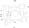
FIG. 1 is a structural schematic view of a cells contact system (CCS) assembly according to an embodiment of the present disclosure. -
FIG. 2 is a structural schematic view of the temperature obtaining member shown inFIG. 1 being partially mounted in the plastic bracket. -
FIG. 3 is an exploded view of the temperature obtaining member shown inFIG. 1 . -
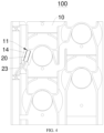
FIG. 4 is a structural schematic view of the cells contact system (CCS) assembly according to another embodiment of the present disclosure. -
FIG. 5 is a structural schematic view of the temperature obtaining member shown inFIG. 4 being mounted in the plastic bracket. -
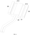
FIG. 6 is an exploded view of the temperature obtaining member and the connection portion shown inFIG. 4 . -
FIG. 7 is a structural schematic view of the connection portion according to an embodiment of the present disclosure. -
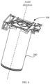
FIG. 8 is a structural schematic view of a battery module having the CCS assembly according to an embodiment of the present disclosure. - 100-CCS assembly, 10-plastic bracket, 11-through groove, 12-guide, 13-notch, 14-pressing block, 15-gap, 20-temperature obtaining member, 21-encapsulation member, 211-slide groove, 212-protrusion, 213-connecting surface, 22-temperature sensor, 23-wire harness, 30-connection portion, 31-compressible layer, 32-adhesive layer.
- For better understanding and implementation, technical solutions in embodiments of the present disclosure will be clearly and completely described below by referring to the accompanying drawings.
- In the present disclosure, it is to be noted that terms "up", "down", "front", "rear", "left", "right", "vertical", "horizontal", "top", "bottom", "in", "out", and so on, indicate an orientation or a positional relationship based on the accompanying drawings. The terms are used only for the purpose of facilitating and simplifying description of the present disclosure, but are not to indicate or imply that a device or an element must have a specific orientation or constructed and operated in a specific orientation. Therefore, the terms shall not be interpreted as limiting the present disclosure.
- Unless otherwise defined, all technical and scientific terms used herein have the same meaning as commonly understood by any ordinary skilled person in the art. The terms used herein in the specification of the present disclosure are for the purpose of describing specific embodiments and are not to limit the present disclosure.
- The present disclosure will be described in further detail below by referring to the accompanying drawings.
- As shown in
FIGs. 1 to 3 , the present embodiment provides a cells contact system (CCS)assembly 100. TheCCS assembly 100 is disposed on a top of a battery group and includes aplastic bracket 10, atemperature obtaining member 20, and a connection portion 30 (as shown inFIG. 4 ). - The
plastic bracket 10 is defines a throughgroove 11. Thetemperature obtaining member 20 is received in thethrough groove 11. Thetemperature obtaining member 20 includes atemperature sensor 22 and anencapsulation member 21 that sleeves an outside of thetemperature sensor 22. Thetemperature sensor 22 is configured to collect a temperature of the battery group. Theencapsulation member 21 has a connectingsurface 213 connected to theplastic bracket 10. Theconnection portion 30 is configured to connect the connectingsurface 213 with theplastic bracket 10, such that theplastic bracket 10 prevents thetemperature obtaining member 20 from detaching from theplastic bracket 10 in an axial direction of the battery group. - For the
above CCS assembly 100, theplastic bracket 10 defines the throughgroove 11, theencapsulation member 21 sleeves the outside of thetemperature sensor 22 to form thetemperature obtaining member 20, and theencapsulation member 21 has the connectingsurface 213 connected to theplastic bracket 10. While thetemperature obtaining member 20 is being mounted with theplastic bracket 10, theconnection portion 30 is disposed and connected between the connectingsurface 213 and theplastic bracket 10, such that a contact area between theencapsulation member 21 and theplastic bracket 10 is larger, and that is, a larger connection area is achieved. In this way, connection between thetemperature obtaining member 20 and theplastic bracket 10 is more stable. In addition, theplastic bracket 10 prevents thetemperature obtaining member 20 from being detached along the axial direction of the battery group, such that thetemperature sensor 22 is prevented from detaching from theplastic bracket 10, and therefore, the temperature detected by thetemperature sensor 22 may not be jumping abnormally. - Specifically, the
connection portion 30 of the present embodiment is a structural adhesive. After theCCS assembly 100 is mounted to the top of the battery group, the structural adhesive is filled into theCCS assembly 100. The structural adhesive may flow to reach a space between theencapsulation member 21 and the plastic bracket. After the structural adhesive solidifies, the structural adhesive is disposed and connects between theencapsulation member 21 and theplastic bracket 10. In addition, the structural adhesive may further penetrate to reach a space between theCCS assembly 100 and the top of the battery. In this way, the structural adhesive allows theCCS assembly 100 to be connected to the battery group to form a one-piece and integral structure. Therefore, a position of thetemperature obtaining member 20 is fixed, and thetemperature obtaining member 20 is avoided from sliding relative to theplastic bracket 10. - Understandably, since the
encapsulation member 21 encapsulates the outside of thetemperature sensor 22, thetemperature sensor 22 is isolated and protected from water. In addition, since thetemperature sensor 22 needs to collect the temperature of the battery group accurately and in real time, theencapsulation member 21 in the present embodiment has a certain thermal conductivity allowing heat generated within the battery group to be transferred to thetemperature sensor 22, such that thetemperature sensor 22 may monitor the temperature in real time. - While forming the connecting
surface 213 on theencapsulation member 21, in the present embodiment, apressing block 14 is arranged on at least one side groove wall of the throughgroove 11, and aprotrusion 212 is arranged on at least one side wall of theencapsulation member 21. Theprotrusion 212 has the connectingsurface 213. Along the axial direction of the battery group, theprotrusion 212 is located below thepressing block 14. For example, theprotrusion 212 is received in the throughgroove 11 and is located between thepressing block 14 and a bottom wall of the throughgroove 11. Theconnection portion 30 is configured to connect theprotrusion 212 with thepressing block 14. For example, when filling the connecting adhesive to serve as theconnection portion 30, the connecting adhesive is formed between theprotrusion 212 and thepressing block 14. In this way, limiting the position of thetemperature obtaining member 20 is achieved by theprotrusion 212 connecting with thepressing block 14. - Specifically, the
pressing block 14 is arranged on one groove wall of the throughgroove 11, and aguide 12 is arranged on another groove wall of the throughgroove 11. Theprotrusion 212 is arranged on one side wall of theencapsulation member 21, and aslide groove 211 is defined in another side wall of theencapsulation member 21. Theguide 12 is received in theslide groove 211, such that theguide 12 is slidably connected with theslide groove 211. An extension direction of theguide 12 is parallel to a plane in which the top (such as a top surface) of the battery group is located. In this way, thetemperature obtaining member 20 may be mounted to a predetermined position in the throughgroove 11 by sliding along theguide 12 due to the slidable connection between theguide 12 and theslide groove 211. Further, since theguide 12 is arranged on theplastic bracket 10 and theslide groove 211 is defined in theencapsulation member 21, theguide 12 and theslide groove 211 may be formed easily. In addition, when thetemperature obtaining member 20 is inserted into the throughgroove 11, only one side of thetemperature obtaining member 20 having theslide groove 211 needs to be aligned with theguide 12, and the other side of thetemperature obtaining member 20 is not restricted by theguide 12. In this way, more space is available while thetemperature obtaining member 20 is being inserted, such that a mounting efficiency is improved. Furthermore, when the connection portion filled within the battery group and between the battery group and theCCS assembly 100 is expanding and deformed to drive thetemperature obtaining member 20 to move in the axial direction of the battery group, thepressing block 14 may press theprotrusion 212 to prevent thetemperature obtaining member 20 from moving excessively, such that the temperature collected by thetemperature obtaining member 20 may not be affected or jumping. In other embodiments, theguide 12 may be arranged on the side wall of theencapsulation member 21, and theslide groove 211 may be defined in the groove wall of the throughgroove 11, according to demands. In this case, the slidable connection between theencapsulation member 21 and theplastic bracket 10 may also be achieved. - Further, since a size of the
temperature obtaining member 20 is small and a size of the throughgroove 11 is small, a side of theguide 12 facing towards an inlet of the throughgroove 11 defines anotch 13, such that a length of theguide 12 is less than a length of theslide groove 211, and therefore, the entiretemperature obtaining member 20 may be received in the throughgroove 11 easily. In this way, while thetemperature obtaining member 20 is being inserted into the throughgroove 11, a larger space is available at the inlet of the throughgroove 11, and theguide 12 may slide to be received into theslide groove 211 of theencapsulation member 21 of thetemperature obtaining member 20 easily. - Further, in order to facilitate production of the
plastic bracket 10, a length of thepressing block 14 is less than a length of theprotrusion 212 along a mounting direction of thetemperature obtaining member 20. Due to the smaller length of thepressing block 14, theplastic bracket 10 may be formed easily. Thepressing block 14 may be located on a top of theprotrusion 212, as long as the position of thetemperature obtaining member 20 is limited. - In addition, along the mounting direction of the
temperature obtaining member 20, thepressing block 14 of the present embodiment is disposed at a middle portion of the throughgroove 11. That is, theencapsulation member 21 has a first end portion near the inlet of the throughgroove 11, a second end portion away from the inlet of the throughgroove 11, and a middle portion disposed between the first end portion and the second end portion. Thepressing block 14 is disposed corresponding to the middle portion. In this way, thepressing block 14 may be easily formed on theplastic bracket 10 and may not be obstructed by any other structure of theplastic bracket 10. - For the
protrusion 212 in the present embodiment, a bottom wall of theprotrusion 212 and a bottom wall of theencapsulation member 21 are co-planar. In other embodiments, theprotrusion 212 may be disposed at a middle of the side wall of theencapsulation member 21. - Further, after the
CCS assembly 100 is disposed on the top of the battery group, the structural adhesive may be poured to allow the structural adhesive, theCCS assembly 100, and the battery group to form a one-piece and integral structure. Agap 15 is defined between each of two opposite side walls of theencapsulation member 21 and the wall of the throughgroove 11. Therefore, the structural adhesive, when being poured, may flow into the space between theCCS assembly 100 and the battery group through thegap 15, such that theCCS assembly 100 and the battery group form the one-piece and integral structure. -
FIG. 3 shows a schematic view of the temperature obtaining member of the present embodiment. Thetemperature sensor 22 of the present embodiment is a temperature sensor having a droplet-shaped head, i.e., the outer surface of thetemperature sensor 22 is curved. The temperature sensor having the droplet-shaped head is encapsulated inside theencapsulation member 21. Thetemperature obtaining member 20 further includes awire harness 23 connected to the temperature sensor having the droplet-shaped head. A position of thewire harness 23 is limited by a block of theplastic bracket 10. - For the above-described
CCS assembly 100, theguide 12 is arranged on theplastic bracket 10, and theslide groove 211 is defined in theencapsulation member 21. By engaging theguide 12 with theslide groove 211, the entiretemperature obtaining member 20 may move only along a direction parallel to the plane on which the top of the battery group is located. Theplastic bracket 10 prevents thetemperature obtaining member 20 from being detached along the axial direction of the battery group, such that thetemperature sensor 22 is prevented from being detached from theplastic bracket 10, and the temperature detected by thetemperature sensor 22 may not jump abnormally. In addition, when thetemperature sensor 22 and theplastic bracket 10 are fixed with each other by the back adhesive, an operation of tearing the back adhesive to adhere to the battery group may be avoided. A risk of thetemperature sensor 22 being detached, due to aging of the back adhesive, from theplastic bracket 10 may be avoided. Furthermore, a risk of thewiring harness 23 connected to thetemperature sensor 22 peeling off the adhesive may be avoided. The mounting efficiency may be improved, and labor costs for mounting may be reduced. - As shown in
FIGS. 4 to 7 , aCCS assembly 100 is provided. TheCCS assembly 100 of the present embodiment is substantially the same as theCCS assembly 100 of the first embodiment. Differences there between include the following. Theconnection portion 30 of the present embodiment includes acompressible layer 31 and twoadhesive layers 32 respectively disposed on two opposite sides of thecompressible layer 31. One of the twoadhesive layers 32 is connected to the connectingsurface 213, and the other one of the twoadhesive layers 32 is connected to thebracket 10. In this case, theconnection portion 30 is directly connected between theencapsulation member 21 and thebracket 10. Since theconnection portion 30 includes thecompressible layer 31 and thecompressible layer 31 can be compressed, a thickness of theentire connection portion 30 is greater than a distance between thebracket 10 and thetemperature obtaining member 20 while thetemperature obtaining member 20 is being mounted with thebracket 10. Specifically, theprotrusion 212 has a connectingsurface 213 facing thepressing block 14. Thepressing block 14 has a block connecting surface facing theprotrusion 212. Theentire connection portion 30 is disposed between the the connectingsurface 213 of theprotrusion 212 and the block connecting surface. A firstadhesive layer 32 of theconnection portion 30 is arranged on the connectingsurface 213 of theprotrusion 212, and the secondadhesive layer 32 is arranged on the block connecting surface. The thickness of theentire connection portion 30 refers to a distance from an outer surface of the firstadhesive layer 32 to an outer surface of the secondadhesive layer 32. The distance between theholder 10 and thetemperature obtaining member 20 is a distance from the connectingsurface 213 of theprotrusion 212 to the block connecting surface. When thetemperature obtaining member 20 and thebracket 10 are being mounted, thecompressible layer 31 is compressed, such that theencapsulation member 21 may abut against and applies a force to an upper surface of the battery group, allowing the temperature of the battery group to be collected. - In order to ensure the connection between the
temperature obtaining member 20 and thebracket 10 to be stable, twoprotrusions 212 are respectively arranged on two opposite sides of theencapsulation member 21, twopressing blocks 14 are respectively arranged on two opposite side walls of the throughgroove 11. The twoprotrusions 212 are connected to the twopressing blocks 14 in one-to-one correspondence through theconnection portion 30. - Specifically, the
compressible layer 31 of the present embodiment is a compressible and insulating material, such as foam, sponge, and the like. - The present embodiment provides a battery module including a
battery group 200 and theCCS assembly 100 as described above. - The
CCS assembly 100 is disposed at the top of thebattery group 200 along the axial direction of thebattery group 200 and is electrically connected to thebattery group 200 to collect voltage signals and current signals of thebattery group 200. - Furthermore, after the
CCS assembly 100 is arranged on the top of thebattery group 200 and electrically connected to thebattery group 200, based on the structure of theCCS assembly 100 of the first embodiment, the structural adhesive is poured to theCCS assembly 100 to enable the CSS assembly and the battery group to form the one-piece and integral structure. - The technical solutions disclosed in the present disclosure are not limited to those disclosed in the above embodiments but further include technical solutions composed of any combination of the above technical features. It should be noted that, any ordinary skilled person in the art may perform improvements and embellishments on the present disclosure without departing from the principle of the present disclosure, and the improvements and embellishments shall fall within the scope of the present disclosure.
Claims (10)
- A cells contact system (CCS) assembly, arranged on a top of a battery group (200), the CCS assembly characterized by comprising:a plastic bracket (10), defining a through groove;a temperature obtaining member (20), received in the through groove (11) and comprising a temperature sensor (22) and an encapsulation member (21) sleeving an outside of the temperature sensor (22), wherein the temperature sensor (22) is configured to obtain a temperature of the battery group (200), the encapsulation member (21) has a connecting surface (213) connected to the plastic bracket (10);a connection portion (30), configured to connect the connecting surface (213) to the plastic bracket (10) and abutting against the temperature obtaining member (20), wherein the plastic bracket (10) and the connection portion (30) cooperatively prevents the temperature obtaining member (20) from detaching from the plastic bracket (10) in an axial direction of the battery group (200).
- The CCS assembly according to claim 1, wherein, a pressing block (14) is arranged on at least one side groove wall of the through groove (11), a protrusion (212) is arranged on at least one side wall of the encapsulation member (21), the protrusion (212) has the connecting surface (213), the protrusion (212) is disposed below the pressing block (14) along the axial direction of the battery group (200), the connection portion (30) connects the protrusion (212) to the pressing block (14).
- The CCS assembly according to claim 2, wherein the at least one side groove wall of the through groove (11) comprises two side groove walls, the pressing block (14) is arranged on one of the two side groove walls, a guide (12) is arranged on the other one of the two side groove walls;the at least one side wall of the encapsulation member (21) comprises two side walls, the protrusion (212) is arranged on one of the two side walls, a slide groove (211) is defined in the other one of the two side walls;the guide (12) is slidably connected with the slide groove (211).
- The CCS assembly according to claim 3, wherein a side of the guide (12) facing towards an inlet of the through groove (11) has a notch, a length of the guide (12) is less than a length of the slide groove (211).
- The CCS assembly according to claim 3, wherein a length of the pressing block (14) is less than a length of the protrusion (212) along a direction of the temperature obtaining member (20) being mounted.
- The CCS assembly according to claim 5, wherein the pressing block (14) is disposed at a middle of the through groove (11) along the direction of the temperature obtaining member (20) being mounted.
- The CCS assembly according to any one of claims 2 to 6, wherein a bottom wall of the protrusion (212) and a bottom wall of the encapsulation member (21) are co-planar.
- The CCS assembly according to any one of claims 1 to 6, wherein each of two opposite side walls of the encapsulation member (21) is spaced apart from a corresponding groove wall of the through groove.
- The CCS assembly according to claim 2, wherein the connection portion (30) comprises a compressible layer (31) and two adhesive layers (32) respectively disposed on two opposite sides of the compressible layer (31), one of the two adhesive layers (32) is connected to the connecting surface (213), and the other one of the two adhesive layers (32) is connected to the plastic bracket (10).
- A battery module, comprising:a battery group (200), andthe cells contact system (CCS) assembly according to any one of the claims 1 to 9, arranged on a top of the battery group (200).
Applications Claiming Priority (1)
| Application Number | Priority Date | Filing Date | Title |
|---|---|---|---|
| CN202322313273.9U CN220856856U (en) | 2023-08-25 | 2023-08-25 | CCS assembly and battery module |
Publications (1)
| Publication Number | Publication Date |
|---|---|
| EP4513618A1 true EP4513618A1 (en) | 2025-02-26 |
Family
ID=89474095
Family Applications (1)
| Application Number | Title | Priority Date | Filing Date |
|---|---|---|---|
| EP24150008.1A Pending EP4513618A1 (en) | 2023-08-25 | 2024-01-02 | Ccs assembly and battery module |
Country Status (4)
| Country | Link |
|---|---|
| US (1) | US20240128581A1 (en) |
| EP (1) | EP4513618A1 (en) |
| CN (1) | CN220856856U (en) |
| WO (1) | WO2025043934A1 (en) |
Citations (5)
| Publication number | Priority date | Publication date | Assignee | Title |
|---|---|---|---|---|
| US20120315508A1 (en) * | 2011-06-08 | 2012-12-13 | Honda Motor Co., Ltd | Battery module |
| JP5818105B2 (en) * | 2012-10-31 | 2015-11-18 | 株式会社オートネットワーク技術研究所 | Wiring module |
| US9356326B2 (en) * | 2012-02-23 | 2016-05-31 | Samsung Sdi Co., Ltd. | Top cover and battery pack having the same |
| US20180183079A1 (en) * | 2016-12-28 | 2018-06-28 | Honda Motor Co., Ltd. | Temperature detecting device and insertion hole structure of base |
| EP3800729A1 (en) * | 2019-06-28 | 2021-04-07 | Contemporary Amperex Technology Co., Limited | Battery module and device |
Family Cites Families (6)
| Publication number | Priority date | Publication date | Assignee | Title |
|---|---|---|---|---|
| JP5105746B2 (en) * | 2006-02-08 | 2012-12-26 | 三洋電機株式会社 | Pack battery |
| CN207779574U (en) * | 2018-01-31 | 2018-08-28 | 长城汽车股份有限公司 | Heat detector mounting assembly and battery for battery |
| JP7252184B2 (en) * | 2020-10-09 | 2023-04-04 | 矢崎総業株式会社 | Temperature sensor installation structure and temperature sensor |
| CN217881643U (en) * | 2022-08-11 | 2022-11-22 | 小米汽车科技有限公司 | Temperature acquisition module, battery package and vehicle |
| CN115507261A (en) * | 2022-09-15 | 2022-12-23 | 湖北亿纬动力有限公司 | Fixing frame, temperature sensor assembly and battery module |
| CN218783080U (en) * | 2022-11-11 | 2023-03-31 | 湖北亿纬动力有限公司 | CCS subassembly, battery module and battery package |
-
2023
- 2023-08-25 CN CN202322313273.9U patent/CN220856856U/en active Active
- 2023-12-04 WO PCT/CN2023/136263 patent/WO2025043934A1/en active Pending
- 2023-12-29 US US18/399,701 patent/US20240128581A1/en active Pending
-
2024
- 2024-01-02 EP EP24150008.1A patent/EP4513618A1/en active Pending
Patent Citations (5)
| Publication number | Priority date | Publication date | Assignee | Title |
|---|---|---|---|---|
| US20120315508A1 (en) * | 2011-06-08 | 2012-12-13 | Honda Motor Co., Ltd | Battery module |
| US9356326B2 (en) * | 2012-02-23 | 2016-05-31 | Samsung Sdi Co., Ltd. | Top cover and battery pack having the same |
| JP5818105B2 (en) * | 2012-10-31 | 2015-11-18 | 株式会社オートネットワーク技術研究所 | Wiring module |
| US20180183079A1 (en) * | 2016-12-28 | 2018-06-28 | Honda Motor Co., Ltd. | Temperature detecting device and insertion hole structure of base |
| EP3800729A1 (en) * | 2019-06-28 | 2021-04-07 | Contemporary Amperex Technology Co., Limited | Battery module and device |
Also Published As
| Publication number | Publication date |
|---|---|
| WO2025043934A1 (en) | 2025-03-06 |
| CN220856856U (en) | 2024-04-26 |
| US20240128581A1 (en) | 2024-04-18 |
Similar Documents
| Publication | Publication Date | Title |
|---|---|---|
| KR102002515B1 (en) | Battery module with temperature monitoring assembly | |
| US11450897B2 (en) | Battery module | |
| CN205861226U (en) | Temperature measuring equipment, electric appliance component and battery bag | |
| KR20200080074A (en) | A battery module having a connector mounted on an FPCB, a battery pack and a vehicle comprising the same | |
| CN104752639A (en) | Power battery module | |
| KR20200080076A (en) | A battery module having a structure capable of accurate temperature sensing, a battery pack and a vehicle comprising the same | |
| CN218731672U (en) | Collection assembly and battery module | |
| KR102700560B1 (en) | Jig for mounting a sensing assembly and method for assembling a battery module using the same | |
| EP3944407B1 (en) | Battery module | |
| WO2020259173A1 (en) | Battery module and device | |
| CN114709659A (en) | Power contact pin cooling module, charging connector | |
| CN112331944A (en) | Battery module | |
| EP4513618A1 (en) | Ccs assembly and battery module | |
| US11982712B2 (en) | Terminal module | |
| EP3926730B1 (en) | Battery module | |
| EP3951804A1 (en) | Ffc cable assembly | |
| EP3644397B1 (en) | Battery module for supplying power for emergency call | |
| CN110190202A (en) | Car battery and vehicle | |
| CN216413142U (en) | A battery pack and electrical equipment | |
| CN212033123U (en) | Busbars, electrical connection components and battery packs for battery packs | |
| CN210257973U (en) | Vehicle storage battery and housing thereof | |
| CN219269158U (en) | A circuit board assembly and battery pack | |
| CN213584052U (en) | A protection component and square battery module for battery module | |
| CN212030769U (en) | Temperature sensor assembly, electrical connection assembly and battery pack | |
| JP2007059279A (en) | Battery housing and battery pack |
Legal Events
| Date | Code | Title | Description |
|---|---|---|---|
| STAA | Information on the status of an ep patent application or granted ep patent |
Free format text: STATUS: EXAMINATION IS IN PROGRESS |
|
| PUAI | Public reference made under article 153(3) epc to a published international application that has entered the european phase |
Free format text: ORIGINAL CODE: 0009012 |
|
| 17P | Request for examination filed |
Effective date: 20240102 |
|
| AK | Designated contracting states |
Kind code of ref document: A1 Designated state(s): AL AT BE BG CH CY CZ DE DK EE ES FI FR GB GR HR HU IE IS IT LI LT LU LV MC ME MK MT NL NO PL PT RO RS SE SI SK SM TR |