EP4513617A2 - Battery module, battery pack and electrical device - Google Patents
Battery module, battery pack and electrical device Download PDFInfo
- Publication number
- EP4513617A2 EP4513617A2 EP24196082.2A EP24196082A EP4513617A2 EP 4513617 A2 EP4513617 A2 EP 4513617A2 EP 24196082 A EP24196082 A EP 24196082A EP 4513617 A2 EP4513617 A2 EP 4513617A2
- Authority
- EP
- European Patent Office
- Prior art keywords
- segment
- opening
- battery
- battery module
- connecting portion
- Prior art date
- Legal status (The legal status is an assumption and is not a legal conclusion. Google has not performed a legal analysis and makes no representation as to the accuracy of the status listed.)
- Pending
Links
Images


Classifications
-
- H—ELECTRICITY
- H01—ELECTRIC ELEMENTS
- H01M—PROCESSES OR MEANS, e.g. BATTERIES, FOR THE DIRECT CONVERSION OF CHEMICAL ENERGY INTO ELECTRICAL ENERGY
- H01M50/00—Constructional details or processes of manufacture of the non-active parts of electrochemical cells other than fuel cells, e.g. hybrid cells
- H01M50/20—Mountings; Secondary casings or frames; Racks, modules or packs; Suspension devices; Shock absorbers; Transport or carrying devices; Holders
- H01M50/204—Racks, modules or packs for multiple batteries or multiple cells
- H01M50/207—Racks, modules or packs for multiple batteries or multiple cells characterised by their shape
- H01M50/211—Racks, modules or packs for multiple batteries or multiple cells characterised by their shape adapted for pouch cells
-
- H—ELECTRICITY
- H01—ELECTRIC ELEMENTS
- H01M—PROCESSES OR MEANS, e.g. BATTERIES, FOR THE DIRECT CONVERSION OF CHEMICAL ENERGY INTO ELECTRICAL ENERGY
- H01M50/00—Constructional details or processes of manufacture of the non-active parts of electrochemical cells other than fuel cells, e.g. hybrid cells
- H01M50/50—Current conducting connections for cells or batteries
- H01M50/569—Constructional details of current conducting connections for detecting conditions inside cells or batteries, e.g. details of voltage sensing terminals
-
- H—ELECTRICITY
- H01—ELECTRIC ELEMENTS
- H01M—PROCESSES OR MEANS, e.g. BATTERIES, FOR THE DIRECT CONVERSION OF CHEMICAL ENERGY INTO ELECTRICAL ENERGY
- H01M10/00—Secondary cells; Manufacture thereof
- H01M10/04—Construction or manufacture in general
-
- H—ELECTRICITY
- H01—ELECTRIC ELEMENTS
- H01M—PROCESSES OR MEANS, e.g. BATTERIES, FOR THE DIRECT CONVERSION OF CHEMICAL ENERGY INTO ELECTRICAL ENERGY
- H01M10/00—Secondary cells; Manufacture thereof
- H01M10/42—Methods or arrangements for servicing or maintenance of secondary cells or secondary half-cells
- H01M10/425—Structural combination with electronic components, e.g. electronic circuits integrated to the outside of the casing
-
- H—ELECTRICITY
- H01—ELECTRIC ELEMENTS
- H01M—PROCESSES OR MEANS, e.g. BATTERIES, FOR THE DIRECT CONVERSION OF CHEMICAL ENERGY INTO ELECTRICAL ENERGY
- H01M10/00—Secondary cells; Manufacture thereof
- H01M10/42—Methods or arrangements for servicing or maintenance of secondary cells or secondary half-cells
- H01M10/48—Accumulators combined with arrangements for measuring, testing or indicating the condition of cells, e.g. the level or density of the electrolyte
- H01M10/482—Accumulators combined with arrangements for measuring, testing or indicating the condition of cells, e.g. the level or density of the electrolyte for several batteries or cells simultaneously or sequentially
-
- H—ELECTRICITY
- H01—ELECTRIC ELEMENTS
- H01M—PROCESSES OR MEANS, e.g. BATTERIES, FOR THE DIRECT CONVERSION OF CHEMICAL ENERGY INTO ELECTRICAL ENERGY
- H01M10/00—Secondary cells; Manufacture thereof
- H01M10/42—Methods or arrangements for servicing or maintenance of secondary cells or secondary half-cells
- H01M10/48—Accumulators combined with arrangements for measuring, testing or indicating the condition of cells, e.g. the level or density of the electrolyte
- H01M10/486—Accumulators combined with arrangements for measuring, testing or indicating the condition of cells, e.g. the level or density of the electrolyte for measuring temperature
-
- H—ELECTRICITY
- H01—ELECTRIC ELEMENTS
- H01M—PROCESSES OR MEANS, e.g. BATTERIES, FOR THE DIRECT CONVERSION OF CHEMICAL ENERGY INTO ELECTRICAL ENERGY
- H01M50/00—Constructional details or processes of manufacture of the non-active parts of electrochemical cells other than fuel cells, e.g. hybrid cells
- H01M50/20—Mountings; Secondary casings or frames; Racks, modules or packs; Suspension devices; Shock absorbers; Transport or carrying devices; Holders
- H01M50/244—Secondary casings; Racks; Suspension devices; Carrying devices; Holders characterised by their mounting method
-
- H—ELECTRICITY
- H01—ELECTRIC ELEMENTS
- H01M—PROCESSES OR MEANS, e.g. BATTERIES, FOR THE DIRECT CONVERSION OF CHEMICAL ENERGY INTO ELECTRICAL ENERGY
- H01M50/00—Constructional details or processes of manufacture of the non-active parts of electrochemical cells other than fuel cells, e.g. hybrid cells
- H01M50/20—Mountings; Secondary casings or frames; Racks, modules or packs; Suspension devices; Shock absorbers; Transport or carrying devices; Holders
- H01M50/284—Mountings; Secondary casings or frames; Racks, modules or packs; Suspension devices; Shock absorbers; Transport or carrying devices; Holders with incorporated circuit boards, e.g. printed circuit boards [PCB]
-
- H—ELECTRICITY
- H01—ELECTRIC ELEMENTS
- H01M—PROCESSES OR MEANS, e.g. BATTERIES, FOR THE DIRECT CONVERSION OF CHEMICAL ENERGY INTO ELECTRICAL ENERGY
- H01M50/00—Constructional details or processes of manufacture of the non-active parts of electrochemical cells other than fuel cells, e.g. hybrid cells
- H01M50/50—Current conducting connections for cells or batteries
- H01M50/502—Interconnectors for connecting terminals of adjacent batteries; Interconnectors for connecting cells outside a battery casing
- H01M50/519—Interconnectors for connecting terminals of adjacent batteries; Interconnectors for connecting cells outside a battery casing comprising printed circuit boards [PCB]
-
- H—ELECTRICITY
- H01—ELECTRIC ELEMENTS
- H01M—PROCESSES OR MEANS, e.g. BATTERIES, FOR THE DIRECT CONVERSION OF CHEMICAL ENERGY INTO ELECTRICAL ENERGY
- H01M10/00—Secondary cells; Manufacture thereof
- H01M10/42—Methods or arrangements for servicing or maintenance of secondary cells or secondary half-cells
- H01M10/425—Structural combination with electronic components, e.g. electronic circuits integrated to the outside of the casing
- H01M2010/4271—Battery management systems including electronic circuits, e.g. control of current or voltage to keep battery in healthy state, cell balancing
-
- H—ELECTRICITY
- H01—ELECTRIC ELEMENTS
- H01M—PROCESSES OR MEANS, e.g. BATTERIES, FOR THE DIRECT CONVERSION OF CHEMICAL ENERGY INTO ELECTRICAL ENERGY
- H01M50/00—Constructional details or processes of manufacture of the non-active parts of electrochemical cells other than fuel cells, e.g. hybrid cells
- H01M50/20—Mountings; Secondary casings or frames; Racks, modules or packs; Suspension devices; Shock absorbers; Transport or carrying devices; Holders
- H01M50/247—Mountings; Secondary casings or frames; Racks, modules or packs; Suspension devices; Shock absorbers; Transport or carrying devices; Holders specially adapted for portable devices, e.g. mobile phones, computers, hand tools or pacemakers
-
- Y—GENERAL TAGGING OF NEW TECHNOLOGICAL DEVELOPMENTS; GENERAL TAGGING OF CROSS-SECTIONAL TECHNOLOGIES SPANNING OVER SEVERAL SECTIONS OF THE IPC; TECHNICAL SUBJECTS COVERED BY FORMER USPC CROSS-REFERENCE ART COLLECTIONS [XRACs] AND DIGESTS
- Y02—TECHNOLOGIES OR APPLICATIONS FOR MITIGATION OR ADAPTATION AGAINST CLIMATE CHANGE
- Y02E—REDUCTION OF GREENHOUSE GAS [GHG] EMISSIONS, RELATED TO ENERGY GENERATION, TRANSMISSION OR DISTRIBUTION
- Y02E60/00—Enabling technologies; Technologies with a potential or indirect contribution to GHG emissions mitigation
- Y02E60/10—Energy storage using batteries
Definitions
- This application relates to the technical field of energy storage, and in particular, a battery module and a manufacturing method therefor, a battery pack and an electrical device.
- battery modules are widely used in the fields of drones, electric vehicles, intelligent energy storage devices, and so on.
- a battery cell is detected through a testing member, and currently there are difficulties in assembling the testing member and the battery cell, resulting in damage to the testing member connected to the battery cell.
- An embodiment of this application provides a battery module including a cell assembly, a testing member, and a first component.
- the cell assembly includes a plurality of battery cells, each of which includes a battery cell housing and electrode terminals.
- the electrode terminals extend out the battery cell housing, and the electrode terminals are disposed on a first side of the battery cell housing.
- the testing member includes a detection portion, a first connecting portion, and a second connecting portion. The first connecting portion connects the detection portion and the second connecting portion, the detection portion is disposed between the battery cell housings, and the second connecting portion is configured to be connected to a circuit board.
- the first component is provided with a first opening, at least a part of the detection portion is disposed in the first opening, and the first connecting portion extends out of the first opening from a second side of the battery cell housing.
- the first opening faces a second side of the cell assembly, which is conductive to assembling the testing member.
- a thickness of the testing member is less than a thickness of the first component, which reduces the risk of damage due to pressure on the testing member.
- the first opening penetrates through the first component along a thickness direction of the first component, which is conductive to the provision of the testing member.
- the first opening extends from a sidewall of the first component.
- a plurality of battery cells are stacked along a first direction, and the detection portion is located between the plurality of battery cells in the middle position, which is conductive to detecting the temperature of the battery cells.
- a binder is further included, and the testing member is connected to the battery cell via the binder, which is conductive to fixing the testing member.
- a holder is further included, at least a part of the cell assembly is disposed within the holder, the holder is provided with a second opening, the holder includes a top wall, and the top wall and the cell assembly are arranged along the first direction. Along the first direction, a part of the second opening penetrates through the top wall. The portion of the first connecting portion is exposed to the second opening. The portion of the second opening may provide a space for movement of the testing member, thereby reducing the risk of damage to the testing member.
- the holder includes a front wall, the front wall is connected to the top wall, and the front wall and the cell assembly are arranged along a second direction.
- a part of the second opening penetrates through the front wall.
- the portion of the first connecting portion is exposed to the second opening.
- the first direction is perpendicular to the second direction.
- the portion of the second opening may provide a space for movement of the testing member, thereby reducing the risk of damage to the testing member.
- the first connecting portion includes a first segment, a second segment, a third segment, and a bent segment.
- the first segment is connected to the detection portion, the first segment is connected to the third segment, the third segment is connected to the second segment, and the second connecting portion is connected to the second segment.
- At least a part of the first segment is disposed between two adjacent battery cell housings.
- the second segment and the first segment are spaced apart along the first direction.
- the third segment is exposed to the first opening.
- the third segment is connected to the first segment and the second segment with the bent segment.
- a part of the bent segment is exposed to the second opening.
- the second opening may provide more space for bending deformation of the bent segment, which is further conductive to lowering stress pull on the bent segment, which in turn further reduces the risk of damage to the testing member.
- the first component in a case where the first component is subjected to the expansion pressure of the battery cells, the first component is configured to have a constant thickness in the first direction, which is conductive to protecting the testing member.
- a second fixing portion is further included, the front wall is provided with a third concave portion, the second fixing portion is disposed in the third concave portion, and a part of the third segment is located between the battery cell housing and the second fixing portion.
- a resilient member is further included, the resilient member is disposed in the second opening, along the second direction, the resilient member is located between the second fixing portion and the first connecting portion, and the resilient member connects the second fixing portion and the first connecting portion.
- the testing member includes a temperature sensor.
- the cell assembly further includes a buffer member, and the buffer member has a resilience coefficient greater than a resilience coefficient of the first component.
- the buffer member is connected to the cell assembly; and/or, the buffer member is disposed between two adjacent battery cells, which is conductive to reducing the risk of damage to the testing member.
- guiding portions are disposed on two sides of the first component, which is conductive to the insertion of the testing member into the first opening.
- the holder includes a first holder and a second holder, the first holder is connected to the second holder to form an accommodation space, and the first opening penetrates through the first holder.
- a first concave portion is disposed on a side of the top wall, the side being oriented back away from the cell assembly, a part of the testing member is disposed in the first concave portion, and a depth of the first concave portion is greater than or equal to a thickness of the testing member along the first direction, which can reduce the space occupied by the testing member in the first direction.
- a first fixing portion is also included, the top wall is provided with a second concave portion, the first fixing portion is disposed in the second concave portion, and the testing member is located between the top wall and the first fixing portion, which is conductive to fixing the second segment, so as to reduce the upwarping of the second segment and reduce the risk of friction damage of the second segment.
- a depth of the second concave portion is greater than a thickness of the first fixing portion along the first direction, which can reduce the space occupied by the first fixing portion in the first direction.
- a second fixing portion is further included, the front wall is provided with a third concave portion, the second fixing portion is disposed in the third concave portion, and a part of the testing member is located between the battery cell housing and the second fixing portion, which is conductive to fixing the portion of the first bent segment, reducing the deformation of the first bent segment, and lowering the risk of friction damage of the first bent segment.
- a depth of the third concave portion is greater than a thickness of the second fixing portion, which can reduce the space occupied by the second fixing portion in the second direction.
- An embodiment of this application provides a manufacturing method for the battery module in any of the above embodiments, including the following steps: placing a first component between two adjacent battery cells and stacking a plurality of battery cells; and inserting an end of a testing member into a first opening from a second side.
- An embodiment of this application provides a battery pack, including the battery module in any of the above embodiments.
- the battery pack further includes a circuit board, the circuit board is disposed on a side of a top wall, the side being oriented back away from the cell assembly, and the second connecting portion is connected to the circuit board.
- An embodiment of this application provides an electrical device, including the battery pack in any of the above embodiments.
- Battery module 100 Cell assembly 10 Battery cell 11 Battery cell housing 111 Body portion 111a First sealing portion 1112 First side 1113 Second side 1114 Second sealing portion 1115 Sealing portion 111b Electrode terminal 112 Second component 101 Conductive plate 102 First fixing portion 103 Second fixing portion 104 Resilient member 105 Holder 20 First holder 201 Second holder 202 Second opening 20a Top wall 21 Arc portion 21a First concave portion 211 Second concave portion 212 Fourth concave portion 213 Front wall 22 Third concave portion 221 Rear wall 23 Right wall 24 Left wall 25 Bottom wall 26 Fifth concave portion 261 Testing member 30 Detection portion 31 First connecting portion 32 First segment 321 Second segment 322 Third segment 323 Bent segment 324 Fourth segment 325 First bent segment 324a Second bent segment 324b Third bent segment 324c Fourth bent segment 324d Circuit board 40 First component 50 First opening 50a Guiding portion 511 Binder 60 Buffer member 70 Connector 80 Shell 90 Battery pack 200 Electrical device 300 First direction X Second direction Y Third direction Z
- perpendicular is used in the technical solutions of this application to describe the ideal state between two components, taking into account the actual machining tolerances. In the actual state of production or use, one component may be approximately perpendicular to another component.
- perpendicular may represent an angle of 90° ⁇ 10° between two straight lines, or a dihedral angle of 90° ⁇ 10° between two planes, or an angle of 90° ⁇ 10° between a straight line and a plane.
- the two components described as “perpendicular” may not absolutely be straight lines or planes, but may also roughly be straight lines or planes. From a macroscopic point of view, components with the overall extension direction being straight lines or planes may be regarded as "straight lines” or "planes".
- first direction X includes along the first direction X and along a direction opposite to the first direction X
- second direction Y includes along the second direction Y and along a direction opposite to the second direction Y
- third direction Z includes along the third direction Z and along a direction opposite to the third direction Z.
- An embodiment of this application provides a battery module including a cell assembly, a testing member, and a first component.
- the cell assembly includes a plurality of battery cells, each of which includes a battery cell housing and electrode terminals.
- the electrode terminals extend out the battery cell housing, and the electrode terminals are located on a first side of the battery cell housing.
- the testing member includes a detection portion, a first connecting portion, and a second connecting portion. The first connecting portion is connected to the detection portion and the second connecting portion, the detection portion is disposed between the battery cell housings, and the second connecting portion is configured to be connected to a circuit board.
- the first component is provided with a first opening, at least a part of the detection portion is located in the first opening, and the first connecting portion extends out of the first opening from a second side of the battery cell housing.
- an embodiment of this application provides a battery module 100 including a cell assembly 10 and a testing member 30, the cell assembly 10 includes a battery cell 11, and the testing member 30 is configured to detect a signal from the battery cell 11.
- the testing member 30 is configured to detect a temperature of the battery cell 11.
- the testing member 30 is configured to detect at least one of current, voltage, resistance, and moisture outside the battery cell housing 111, electrolyte solution outside the battery cell housing 111, and other information of the battery cell 11. This application is described with an example of the testing member 30 detecting the temperature of the battery cell 11.
- the cell assembly 10 includes a plurality of battery cells 11, one end of the testing member 30 is connected to the battery cells 11, and another end of the testing member 30 is configured to be connected to a circuit board 40.
- one end of the testing member 30 is disposed between adjacent battery cells 11; or, one end of the testing member 30 is disposed in a first direction X with the cell assembly 10.
- each battery cell 11 includes a battery cell housing 111, and the testing member 30 is connected to at least one of the battery cell housings 111.
- the cell assembly 10 includes a plurality of battery cells 11 are stacked in the first direction X.
- the testing member 30 is connected to the battery cell housing 111 of the outermost battery cell 11.
- the testing member 30 is disposed between adjacent battery cell housings 111, which is conductive to detecting the temperature of the battery cells 11.
- the testing member 30 is disposed between two adjacent battery cell housings 111 in a middle position of the plurality of battery cells 11.
- the temperature of the battery cells 11 in the middle position is typically higher than the temperature of the battery cells 11 in the outer side, which is further conductive to detecting the temperature of the battery cells 11.
- each battery cell 11 includes an electrode assembly (not illustrated), the electrode assembly being disposed within a body portion 111a.
- the electrode assembly includes a coiled structure formed by stacking and winding a first electrode plate, a separator, and a second electrode plate. In other embodiments, the electrode assembly may also be a laminated structure with the first electrode plate and the second electrode plate having opposite polarities.
- the battery cell 11 includes a pouch battery cell.
- the battery cell 11 includes a prismatic cell.
- the battery cell 11 includes a cylindrical cell.
- each battery cell 11 includes electrode terminals 112, and the electrode terminals 112 are connected to the electrode assembly and extend out the battery cell housing 111.
- Each battery cell housing 111 includes a body portion 111a and a sealing portion 111b, and the sealing portion 111b is connected to the body portion 111a.
- the sealing portion 111b includes a first sealing portion 1112, and the electrode terminals 112 extend out the first sealing portion 1112.
- the sealing portion 111b includes two second sealing portions 1115, the two second sealing portions 1115 are located on two opposite sides of the body portion 111a, and the second sealing portions 1115 are connected to the body portion 111a.
- the battery module 100 includes a holder 20, the holder 20 is provided with a second opening 20a, and the second opening 20a penetrates through the holder 20. At least a part of the cell assembly 10 is disposed within the holder 20.
- a part of the testing member 30 is exposed within the second opening 20a.
- the second opening 20a may provide a space for movement of the testing member 30, reducing the risk of damage to the testing member 30.
- the holder 20 includes a top wall 21, and the top wall 21 and the cell assembly 10 are arranged along the first direction X.
- a part of the second opening 20a penetrates through the second opening 20a.
- a part of the testing member 30 is exposed to the second opening 20a.
- the part of the second opening 20a may provide a space for movement of the testing member 30, reducing the risk of damage to the testing member 30.
- the holder 20 includes a front wall 22, and the front wall 22 is connected to the top wall 21.
- the front wall 22 and the cell assembly 10 are arranged along a second direction Y.
- a part of the second opening 20a penetrates through the front wall 22.
- a part of the testing member 30 is exposed to the second opening 20a.
- the portion of the second opening 20a may provide a space for movement of the testing member 30, reducing the risk of damage to the testing member 30.
- the second opening 20a is opposite to at least one of the body portions 111a.
- the holder 20 includes a rear wall 23, the rear wall 23 is connected to the top wall 21, and the front wall 22 and the rear wall 23 are arranged along the second direction Y.
- the second opening 20a may be disposed at the top wall 21 and the rear wall 23. A part of the second opening 20a penetrates through the top wall 21, and along the first direction X, a part of the testing member 30 is exposed to the second opening 20a. A part of the second opening 20a penetrates through the rear wall 23. Along a direction opposite to the second direction Y, a part of the testing member 30 is exposed to the second opening 20a.
- the holder 20 includes a bottom wall 26, and the top wall 21 and the bottom wall 26 are arranged along the first direction X.
- the bottom wall 26 is connected to the front wall 22, the rear wall 23, the right wall 24, and the left wall 25, and the top wall 21 is connected to the front wall 22, the rear wall 23, the right wall 24, and the left wall 25 to form an accommodation space.
- the top wall 21 includes an arc portion 21a, the arc portion 21a is connected to the front wall 22, and the second opening 20a penetrates through the arc portion 21a.
- the arc portion 21a is connected to at least one of the rear wall 23, the right wall 24, and the left wall 25.
- the holder 20 includes a first holder 201 and a second holder 202, the first holder 201 is connected to the second holder 202 to form the above-described accommodation space, and the second opening 20a penetrates through the first holder 201, which facilitates assembly.
- the first holder 201 is provided as a one-piece injection molding.
- a plurality of second openings 20a and testing members 30 may be provided, and the number of the second openings 20a is the same as the number of the testing members 30.
- a plurality of first openings 50a are provided.
- the number of the first openings 50a is the same as the number of the second openings 20a.
- the plurality of second openings 20a may be located on the same side of the cell assembly 10 or may be provided on different sides of the cell assembly 10, each of the testing members 30 is connected to the battery cell housing 111, and a part of each of the testing members 30 is exposed to one of the second openings 20a.
- the plurality of testing members 30 may detect different electrical signals from the battery cells 11.
- the plurality of testing members 30 may detect the same signal from the battery cells 11.
- the plurality of testing members 30 may be connected to different locations of the battery cell housing 111.
- Two second openings 20a being provided on different sides of the battery cell housing 111 is taken as an example.
- the holder 20 is provided with two second openings 20a
- the battery module 100 includes two testing members 30.
- One of the second openings 20a penetrates through the top wall 21 and the front wall 22, and a part of one of the testing members 30 is exposed to the second opening 20a.
- the other second opening 20a penetrates through the top wall 21 and the rear wall 23, and a part of the other testing member 30 is exposed to the second opening 20a.
- the two testing members 30 different electrical signals from the battery cells 11 can be detected.
- one of the testing members 30 detects the temperature of the battery cells 11 and the other testing member 30 detects the current of the battery cells 11.
- the two testing members 30 may also detect the same electrical signal from the battery cells 11.
- both the testing members 30 detect the temperature of the battery cells 11, which facilitates the comparison of the two detected temperatures, and is conductive to improving the accuracy of the detection.
- the two testing members 30 may also be provided at different locations of the battery cell housing 111, and may detect temperatures at different locations of the battery cell housing 111.
- the distance h1 between the testing member 30 and the body portion 111a is less than half of the length H of the body portion 111a. The closer the testing member 30 is to the electrode terminal 112, the higher the detected temperature of the battery cell 11, which in turn is further conductive to detecting the temperature of the battery cell 11.
- one end of the testing member 30 includes a detection portion 31.
- the detection portion 31 is a temperature sensor.
- the detection portion 31 is disposed between two adjacent battery cell housings 111.
- the testing member 30 includes a first connecting portion 32, and the first connecting portion 32 is connected to the detection portion 31.
- the first connecting portion 32 extends out of the holder 20 from the second opening 20a.
- another end of the testing member 30 includes a second connecting portion 33, the second connecting portion 33 is connected to the first connecting portion 32, and the second connecting portion 33 is configured to be connected to the circuit board 40.
- the second connecting portion 33 is disposed on a side of the holder 20 , the side of the holder 20 being a side facing away from the cell assembly 10.
- the second connecting portion 33 is disposed on a side of the top wall 21, the side of the top wall 21 being a side facing away from the cell assembly 10 and connected to the circuit board 40, which may transmit electrical signals to the circuit board 40.
- the second connecting portion 33 is soldered to the circuit board 40.
- the testing member 30 is substantially U-shaped.
- the first connecting portion 32 includes a first segment 321, the first segment 321 is connected to the detection portion 31, and at least a part of the first segment 321 is disposed between two adjacent battery cell housings 111.
- a projection of the first segment 321 is disposed within a projection of the battery cell housing 111.
- a part of the first segment 321 extends out of the battery cell housing 111.
- the detection portion 31 and the first segment 321 are disposed in the first opening 50a.
- a thickness of the detection portion 31 is less than a thickness of the first component 50
- a thickness of the first segment 321 is less than the thickness of the first component 50.
- the first connecting portion 32 includes a second segment 322, the second segment 322 is disposed at the top wall 21, and the second segment 322 and the first segment 321 are spaced apart along the first direction X.
- the first connecting portion 32 includes a third segment 323, and along the second direction Y, the second segment 322 is disposed on the outer side of the cell assembly 10.
- the first connecting portion 32 includes a bent segment 324.
- the bent segment 324 can reduce stress pull when the testing member 30 is squeezed and moved, further reducing the risk of damage to the testing member 30 due to the testing member 30 being squeezed.
- a part of the bent segment 324 is exposed to the second opening 20a.
- a part of the bent segment 324 is exposed to the second opening 20a, and the second opening 20a may provide more space for bending deformation of the bent segment 324, which is conductive to reducing stress pull on the bent segment 324, and thus reducing the risk of damage to the testing member 30.
- a part of the bent segment 324 is exposed to the second opening 20a, and the second opening 20a may provide more space for bending deformation of the bent segment 324, which is further conductive to reducing stress pull on the bent segment 324, and thus further reducing the risk of damage to the testing member 30.
- the third segment 323 is connected to the first segment 321 and the second segment 322 via the bent segment 324.
- the bent segment 324 includes a first bent segment 324a, and the first bent segment 324a is connected to the first segment 321 and the third segment 323.
- a part of the first bent segment 324a is exposed to the second opening 20a.
- the bent segment 324 includes a second bent segment 324b, and the second bent segment 324b is connected to the second segment 322 and the third segment 323.
- a part of the second bent segment 324b is exposed to the second opening 20a.
- a part of the second bent segment 324b is exposed to the second opening 20a.
- the first connecting portion 32 includes a fourth segment 325, and the fourth segment 325 is connected to the second segment 322 and the second connecting portion 33.
- the bent segment 324 further includes a third bent segment 324c and a fourth bent segment 324d, and the third bent segment 324c is connected to the second segment 322 and the fourth segment 325.
- the fourth bent segment 324d is connected to the fourth segment 325 and the second connecting portion 33, which is conductive to reducing stress pull on the testing member 30, and reducing the risk of damage to the testing member 30.
- the top wall 21 has a first concave portion 211 on a side of the top wall 21, the side being orientedback away from the cell assembly 10, and a portion of the testing member 30 is provided in the first concave portion 211.
- the depth of the first concave portion 211 is greater than the thickness of the testing member 30, which can reduce the space occupied by the testing member 30 in the first direction X.
- At least a portion of the second segment 322 is disposed in the first concave portion 211.
- the depth of the first concave portion 211 is greater than the thickness of the second segment 322.
- the battery module 100 includes a first fixing portion 103, a second concave portion 212 is provided on a side of the top wall 21, the side being oriented back away from the cell assembly 10, the first fixing portion 103 is disposed in the second concave portion 212, and the second segment 322 is located between the first fixing portion 103 and the top wall 21, which is conductive to fixing the second segment 322, so as to reduce the upwarping of the second segment 322 and reduce the risk of friction damage to the second segment 322.
- the depth of the second concave portion 212 is greater than the thickness of the first fixing portion 103, which can reduce the space occupied by the first fixing portion 103 in the first direction X.
- the first fixing portion 103 is bonded to the second concave portion 212.
- the first fixing portion 103 is bonded to the second concave portion 212 by an adhesive.
- the first fixing portion 103 is insulating.
- the first fixing portion 103 includes foam and an adhesive, and the foam is bonded to the second concave portion and the second segment 322 by the adhesive.
- the first fixing portion 103 includes a polycarbonate (PC) sheet.
- the battery module 100 includes a second fixing portion 104, the front wall 22 has a third concave portion 221, and the second opening 20a communicates with the third concave portion 221.
- the second fixing portion 104 is disposed in the third concave portion 221, and a part of the first bent segment 324a is located between the second fixing portion 104 and the battery cell housing 111, which is conductive to fixing the portion of the first bent segment 324a, so as to reduce the deformation of the first bent segment 324a, and reduce the risk of friction damage to the first bent segment 324a.
- the depth of the third concave portion 221 is greater than the thickness of the second fixing portion 104, which can reduce the space occupied by the second fixing portion 104 in the second direction Y.
- the second fixing portion 104 is bonded to the third concave portion 221.
- the second fixing portion 104 is insulating.
- the second fixing portion 104 includes foam and an adhesive, and the foam is bonded to the third concave portion 221 by the adhesive.
- the second fixing portion 104 includes a polycarbonate (PC) sheet.
- the battery module 100 includes a resilient member 105, and the resilient member 105 is insulating.
- the resilient member 105 is disposed within the second opening 20a.
- the resilient member 105 is located between the second fixing portion 104 and the testing member 30, and the resilient member 105 is connected to the second fixing portion 104 and the testing member 30.
- the resilient member 105 is located between the second fixing portion 104 and the third segment 323.
- the resilient member 105 is disposed in the gap between the second fixing portion 104 and the third segment 323, so that the second fixing portion 104 acts on the third segment 323 through the resilient member 105, which is conductive to fixing the position of the testing member 30.
- the resilient member 105 includes foam.
- the distance between the second fixing portion 104 and the third segment 323 is less than the thickness of the resilient member 105, so that the resilient member 105 disposed between the second fixing portion 104 and the third segment 323 is in a compressed state, which is more conductive to fixing the position of the testing member 30.
- the resilience coefficient of the resilient member 105 is less than the resilience coefficient of the second fixing portion 104, thereby enhancing the protection for the testing member 30.
- the second fixing portion 104 and the resilient member 105 are provided as a one-piece molding, which facilitates assembly.
- the battery module 100 includes a first component 50, the first component 50 is disposed between two adjacent cell housings 111, the first component 50 has a first opening 50a, and a part of the testing member 30 is disposed in the first opening 50a, thereby reducing the risk of damage due to pressure on the testing member 30.
- the electrode terminals 112 are located at a first side 1113 of the battery cell housing 111, and a part of the testing member 30 extends out of the first opening 50a from a second side 1114 of the battery cell housing 111.
- the first side 1113 and the second side 1114 are different sides of the battery cell housing 111.
- the second side 1114 is not limited to the orientation shown in FIG. 2 , as long as the second side 1114 is on a different side from the first side 1113.
- the first opening 50a faces the second side 1114 of the cell assembly 10.
- the thickness of the testing member 30 is less than the thickness of the first component 50.
- the testing member 30 is protected by the first component 50, thereby reducing the risk of damage due to pressure on the testing member 30.
- the first opening 50a penetrates through the first component 50.
- the first opening 50a is concavely disposed in a surface of the first component 50, and along the first direction X, the thickness of the testing member 30 is less than the depth of the first opening 50a.
- the first opening 50a extends from a sidewall of the first component 50.
- a part of the testing member 30 is configured to be disposed in the first opening 50a along the second direction Y, which facilitates assembly of the testing member 30.
- the second direction Y is the width direction of the first component 50.
- the first opening 50a penetrates through one of the sidewalls of the first component 50.
- guiding portions 511 disposed on both sides of the first component 50, which facilitates the insertion of the testing member 30 into the first opening 50a.
- the first component 50 in a case where the battery cell 11 is used in a safe range, is configured to have a constant thickness in the first direction X when the first component 50 is subjected to the expansion pressure of the battery cell 11, which is conductive to protecting the testing member 30.
- the first component 50 includes an insulating sheet.
- the first component 50 includes a polycarbonate (PC) sheet.
- being used in a safe range means not exceeding the rated voltage and current of the battery module 100.
- the battery module 100 includes a binder 60. At least a part of the binder 60 is disposed in the first opening 50a.
- the binder 60 is connected to the testing member 30, and the binder 60 is connected to at least one of the adjacent battery cell housings 111.
- the thermal conductivity of the binder 60 is greater than the thermal conductivity of the battery cell housing 111, which is conductive to conducting heat to the testing member 30, and enhancing the accuracy of the detection.
- the binder 60 includes a thermally conductive adhesive.
- the binder 60 is applied to the first segment 321 of the testing member 30 and inserted into the first opening 50a.
- testing member 30 and the battery cell housing 111 are connected in contact.
- the battery module 100 includes a buffer member 70 to provide an expansion space as well as pressure for the battery cell 11.
- the buffer member 70 includes foam.
- the resilience coefficient of the buffer member 70 is greater than the resilience coefficient of the first component 50, which is conductive to reducing the risk of damage to the testing member 30.
- the buffer member 70 is disposed between adjacent battery cells 11.
- the buffer member 70 and the first component 50 are arranged in the first direction X.
- the buffer member 70 and the first component 50 are aligned along the first direction X.
- the first component 50 and the buffer member 70 are arranged along the first direction X.
- the buffer member 70 is disposed between the battery cell housing 111 and the holder 20 to further provide an expansion space as well as pressure for the battery cell 11.
- the top wall 21 has a fourth concave portion 213, a part of the buffer member 70 is disposed in the fourth concave portion 213, and the buffer member 70 is disposed between the battery cell housing 111 and the top wall 21, which is conductive to reducing the thickness of the battery module 100 in the first direction X, and reducing the occupied space.
- the thickness of the buffer member 70 after being compressed is not less than the depth of the fourth concave portion 213.
- the bottom wall 26 has a fifth concave portion 261
- the buffer member 70 is disposed in the fifth concave portion 261
- the buffer member 70 is located between the battery cell housing 111 and the bottom wall 26, which is conductive to reducing the thickness of the battery module 100 in the first direction X, and reducing the occupied space.
- the thickness of the buffer member 70 after being compressed is not less than the depth of the fifth concave portion 261.
- the battery module 100 includes a second component 101 and a plurality of conductive plates 102, and the plurality of conductive plates 102 are disposed on a side of the second component 101, the side being oriented back away from cell assembly 10.
- the plurality of conductive plates 102 are provided insulated from each other. Electrode terminals 112 of the plurality of battery cells 11 pass through the second component 101 and are connected to the plurality of conductive plates 102, such that the plurality of battery cells 11 are connected in series or in parallel.
- the second component 101 includes an insulating holder, and the conductive plates 102 are fixed to the insulating holder.
- the conductive plates 102 and the second component 101 are integrally molded by an injection molding process.
- the second component 101 includes a circuit board.
- the second component 101 includes a plurality of through holes, and the electrode terminals 112 pass through the through holes and then are connected to the conductive plates 102.
- this application further provides a manufacturing method using the above-described battery module 100, the method including the following steps:
- step 1 specifically includes: placing the first component 50 between the battery cell housings 111 of two adjacent battery cells 11, and providing the plurality of battery cells 11 are stacked, such that the first opening 50a faces the second side of the cell assembly 10 as a whole.
- step 1 specifically includes: inserting the detection portion 31 and the first segment 321 of the testing member 30 into the first opening 50a from the second side.
- the above-described manufacturing direction further includes the step: applying the binder 60 to the first segment 321 of the testing member 30 before the testing member 30 is inserted into the first opening 50a, such that the first segment 321 is bonded to the battery cell housing 111 and/ or the first component 50 by the binder 60.
- this application further provides a battery pack 200 using the above-described battery module 100.
- the battery pack 200 further includes a circuit board 40, and the circuit board 40 is disposed on a side of the top wall 21, the side being oriented back away from the cell assembly 10. Another end of the testing member 30 is connected to the circuit board 40.
- the testing member 30 extends out of the holder 20 from the second opening 20a and is connected to a circuit board 40.
- the circuit board 40 is configured to receive electrical signals from the testing member 30.
- the circuit board 40 includes a battery management system (BMS) assembly
- BMS battery management system
- the BMS assembly includes a plurality of electronic components
- the plurality of electronic components realize functions such as controlling, protecting, communicating, calculating power, signaling, transmitting power, and so on, of the battery cell 11.
- the circuit board 40 includes a flexible printed circuit (FPC, Flexible Printed Circuit).
- the circuit board 40 includes a printed circuit board (PCB, Printed Circuit Board), and a plurality of first wires (not shown) are disposed on the circuit board 40.
- the battery pack 200 further includes a connector 80, and the connector 80 is connected to the circuit board 40.
- the connector 80 is configured to be connected to an external device.
- the battery pack 200 includes a shell 90, and the battery module 100 is disposed in the shell 90.
- this application further provides an electrical device 300 using the above-described battery pack 200.
- the electrical device 300 is connected to a connector 80.
- the electrical device 300 of this application may be, but is not limited to, an electronic device, a drone, a backup power source, an electric vehicle, an electric motorcycle, an electric-assisted bicycle, an electric tool, a large battery module for home use, and the like.
Landscapes
- Chemical & Material Sciences (AREA)
- Chemical Kinetics & Catalysis (AREA)
- Electrochemistry (AREA)
- General Chemical & Material Sciences (AREA)
- Engineering & Computer Science (AREA)
- Manufacturing & Machinery (AREA)
- Microelectronics & Electronic Packaging (AREA)
- Battery Mounting, Suspending (AREA)
Abstract
Description
- This application relates to the technical field of energy storage, and in particular, a battery module and a manufacturing method therefor, a battery pack and an electrical device.
- At present, battery modules are widely used in the fields of drones, electric vehicles, intelligent energy storage devices, and so on. Conventionally, a battery cell is detected through a testing member, and currently there are difficulties in assembling the testing member and the battery cell, resulting in damage to the testing member connected to the battery cell.
- In view of this, it is necessary to provide a battery module and a manufacturing method therefor, a battery pack, and an electrical device, which facilitates assembly and reduces the risk of a testing member being squeezed.
- An embodiment of this application provides a battery module including a cell assembly, a testing member, and a first component. The cell assembly includes a plurality of battery cells, each of which includes a battery cell housing and electrode terminals. The electrode terminals extend out the battery cell housing, and the electrode terminals are disposed on a first side of the battery cell housing. The testing member includes a detection portion, a first connecting portion, and a second connecting portion. The first connecting portion connects the detection portion and the second connecting portion, the detection portion is disposed between the battery cell housings, and the second connecting portion is configured to be connected to a circuit board. The first component is provided with a first opening, at least a part of the detection portion is disposed in the first opening, and the first connecting portion extends out of the first opening from a second side of the battery cell housing. By locating the testing member and the electrode terminals on different sides of a body portion, it is conductive to assembling the testing member, the testing member is protected by the first component, and the risk of damage due to pressure on the testing member is reduced.
- Optionally, in some embodiments of this application, the first opening faces a second side of the cell assembly, which is conductive to assembling the testing member.
- Optionally, in some embodiments of this application, a thickness of the testing member is less than a thickness of the first component, which reduces the risk of damage due to pressure on the testing member.
- Optionally, in some embodiments of this application, the first opening penetrates through the first component along a thickness direction of the first component, which is conductive to the provision of the testing member.
- Optionally, in some embodiments of this application, along a width direction of the first component, the first opening extends from a sidewall of the first component.
- Optionally, in some embodiments of this application, a plurality of battery cells are stacked along a first direction, and the detection portion is located between the plurality of battery cells in the middle position, which is conductive to detecting the temperature of the battery cells.
- Optionally, in some embodiments of this application, a binder is further included, and the testing member is connected to the battery cell via the binder, which is conductive to fixing the testing member.
- Optionally, in some embodiments of this application, a holder is further included, at least a part of the cell assembly is disposed within the holder, the holder is provided with a second opening, the holder includes a top wall, and the top wall and the cell assembly are arranged along the first direction. Along the first direction, a part of the second opening penetrates through the top wall. The portion of the first connecting portion is exposed to the second opening. The portion of the second opening may provide a space for movement of the testing member, thereby reducing the risk of damage to the testing member.
- Optionally, in some embodiments of this application, the holder includes a front wall, the front wall is connected to the top wall, and the front wall and the cell assembly are arranged along a second direction. Along the second direction, a part of the second opening penetrates through the front wall. The portion of the first connecting portion is exposed to the second opening. The first direction is perpendicular to the second direction. The portion of the second opening may provide a space for movement of the testing member, thereby reducing the risk of damage to the testing member.
- Optionally, in some embodiments of this application, the first connecting portion includes a first segment, a second segment, a third segment, and a bent segment. The first segment is connected to the detection portion, the first segment is connected to the third segment, the third segment is connected to the second segment, and the second connecting portion is connected to the second segment. At least a part of the first segment is disposed between two adjacent battery cell housings. The second segment and the first segment are spaced apart along the first direction. Along the second direction, the third segment is exposed to the first opening. The third segment is connected to the first segment and the second segment with the bent segment.
- Optionally, in some embodiments of this application, a part of the bent segment is exposed to the second opening. The second opening may provide more space for bending deformation of the bent segment, which is further conductive to lowering stress pull on the bent segment, which in turn further reduces the risk of damage to the testing member.
- Optionally, in some embodiments of this application, in a case where the first component is subjected to the expansion pressure of the battery cells, the first component is configured to have a constant thickness in the first direction, which is conductive to protecting the testing member.
- Optionally, in some embodiments of this application, a second fixing portion is further included, the front wall is provided with a third concave portion, the second fixing portion is disposed in the third concave portion, and a part of the third segment is located between the battery cell housing and the second fixing portion.
- Optionally, in some embodiments of this application, a resilient member is further included, the resilient member is disposed in the second opening, along the second direction, the resilient member is located between the second fixing portion and the first connecting portion, and the resilient member connects the second fixing portion and the first connecting portion. By the resilient member being disposed in a gap between the second fixing portion and the third segment, the second fixing portion is made to act on the third segment through the resilient member, which is conductive to fixing the position of the testing member.
- Optionally, in some embodiments of this application, the testing member includes a temperature sensor.
- Optionally, in some embodiments of this application, the cell assembly further includes a buffer member, and the buffer member has a resilience coefficient greater than a resilience coefficient of the first component. Here, the buffer member is connected to the cell assembly; and/or, the buffer member is disposed between two adjacent battery cells, which is conductive to reducing the risk of damage to the testing member.
- Optionally, in some embodiments of this application, along a third direction, guiding portions are disposed on two sides of the first component, which is conductive to the insertion of the testing member into the first opening.
- Optionally, in some embodiments of this application, the holder includes a first holder and a second holder, the first holder is connected to the second holder to form an accommodation space, and the first opening penetrates through the first holder.
- Optionally, in some embodiments of this application, a first concave portion is disposed on a side of the top wall, the side being oriented back away from the cell assembly, a part of the testing member is disposed in the first concave portion, and a depth of the first concave portion is greater than or equal to a thickness of the testing member along the first direction, which can reduce the space occupied by the testing member in the first direction.
- Optionally, in some embodiments of this application, a first fixing portion is also included, the top wall is provided with a second concave portion, the first fixing portion is disposed in the second concave portion, and the testing member is located between the top wall and the first fixing portion, which is conductive to fixing the second segment, so as to reduce the upwarping of the second segment and reduce the risk of friction damage of the second segment.
- Optionally, in some embodiments of this application, a depth of the second concave portion is greater than a thickness of the first fixing portion along the first direction, which can reduce the space occupied by the first fixing portion in the first direction.
- Optionally, in some embodiments of this application, a second fixing portion is further included, the front wall is provided with a third concave portion, the second fixing portion is disposed in the third concave portion, and a part of the testing member is located between the battery cell housing and the second fixing portion, which is conductive to fixing the portion of the first bent segment, reducing the deformation of the first bent segment, and lowering the risk of friction damage of the first bent segment.
- Optionally, in some embodiments of this application, along the second direction, a depth of the third concave portion is greater than a thickness of the second fixing portion, which can reduce the space occupied by the second fixing portion in the second direction.
- An embodiment of this application provides a manufacturing method for the battery module in any of the above embodiments, including the following steps: placing a first component between two adjacent battery cells and stacking a plurality of battery cells; and inserting an end of a testing member into a first opening from a second side.
- An embodiment of this application provides a battery pack, including the battery module in any of the above embodiments. The battery pack further includes a circuit board, the circuit board is disposed on a side of a top wall, the side being oriented back away from the cell assembly, and the second connecting portion is connected to the circuit board.
- An embodiment of this application provides an electrical device, including the battery pack in any of the above embodiments.
-
-
FIG. 1 illustrates a partial schematic structural diagram of a battery pack in some embodiments; -
FIG. 2 illustrates a schematic exploded view of a part of the battery pack ofFIG. 1 ; -
FIG. 3 illustrates a schematic diagram of a battery cell in some embodiments; -
FIG. 4 illustrates a partial schematic structural diagram of a holder in some embodiments; -
FIG. 5 illustrates a schematic diagram of a battery module in some embodiments; -
FIG. 6 illustrates a partial schematic structural diagram of a battery pack in some embodiments; -
FIG. 7 illustrates a cross-sectional schematic view ofFIG. 1 along the direction II-II; -
FIG. 8 illustrates an enlarged schematic diagram of a partial structure of the battery module inFIG. 7 ; -
FIG. 9 illustrates a schematic diagram of a battery pack from another view in some embodiments; -
FIG. 10 illustrates a schematic view of a battery pack from yet another view in some embodiments; -
FIG. 11 illustrates a schematic view of a battery pack from a further view in some embodiments; -
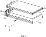
FIG. 12 illustrates a schematic exploded view of a partial structure of a battery module in some embodiments; -
FIG. 13 illustrates a partial schematic structural diagram of a battery pack in some embodiments; -
FIG. 14 illustrates a partial schematic structural diagram of a battery pack in some embodiments; -
FIG. 15 illustrates a schematic structural diagram of a battery cell, a first component, and a testing member in some embodiments; -
FIG. 16 illustrates a cross-sectional schematic view ofFIG. 1 along the direction III-III; -
FIG. 17 illustrates an enlarged schematic diagram of a partial structure of the battery pack inFIG. 16 ; -
FIG. 18 illustrates a schematic flow diagram of a manufacturing method for a battery module in some embodiments; -
FIG. 19 illustrates a schematic structural diagram of a battery pack in some embodiments; and -
FIG. 20 illustrates a schematic structural diagram of an electrical device in some embodiments. -
Battery module 100 Cell assembly 10 Battery cell 11 Battery cell housing 111 Body portion 111a First sealing portion 1112 First side 1113 Second side 1114 Second sealing portion 1115 Sealing portion 111b Electrode terminal 112 Second component 101 Conductive plate 102 First fixing portion 103 Second fixing portion 104 Resilient member 105 Holder 20 First holder 201 Second holder 202 Second opening 20a Top wall 21 Arc portion 21a First concave portion 211 Second concave portion 212 Fourth concave portion 213 Front wall 22 Third concave portion 221 Rear wall 23 Right wall 24 Left wall 25 Bottom wall 26 Fifth concave portion 261 Testing member 30 Detection portion 31 First connecting portion 32 First segment 321 Second segment 322 Third segment 323 Bent segment 324 Fourth segment 325 First bent segment 324a Second bent segment 324b Third bent segment 324c Fourth bent segment 324d Circuit board 40 First component 50 First opening 50a Guiding portion 511 Binder 60 Buffer member 70 Connector 80 Shell 90 Battery pack 200 Electrical device 300 First direction X Second direction Y Third direction Z - This application is further described below with reference to some following specific embodiments and the foregoing drawings.
- The following describes the technical solutions in some embodiments of this application with reference to the drawings hereto. Evidently, some described embodiments are merely a part of but not all of the embodiments of this application.
- It is hereby noted that when one element is referred to as being "connected" to another element, it may be directly connected to the another element or there may also be an element provided therebetween. When one element is referred to as being "provided" or "disposed" on another element, it may be directly disposed on the another element or there may also be an element provided therebetween.
- Unless otherwise defined, all technical and scientific terms used in the description shall have the same meanings as commonly understood by a person skilled in the technical field to which this application belongs. The terms used in the description of this application are merely intended to describe some specific embodiments rather than to limit this application. The term "and/or" used in the description includes any and all combinations of one or more of the relevant listed items.
- It should be understood that the term "perpendicular" is used in the technical solutions of this application to describe the ideal state between two components, taking into account the actual machining tolerances. In the actual state of production or use, one component may be approximately perpendicular to another component. For example, numerically, the term "perpendicular" may represent an angle of 90°±10° between two straight lines, or a dihedral angle of 90°±10° between two planes, or an angle of 90°±10° between a straight line and a plane. The two components described as "perpendicular" may not absolutely be straight lines or planes, but may also roughly be straight lines or planes. From a macroscopic point of view, components with the overall extension direction being straight lines or planes may be regarded as "straight lines" or "planes".
- Unless otherwise defined, all technical and scientific terms used herein have the same meanings as commonly understood by a person skilled in the technical field to which this application belongs. The terms used in the description of this application are merely intended to describe some specific embodiments but not to limit this application.
- The terms "left", "right", "top", "bottom", "front", "back", and other similar expressions used herein are merely for ease of description and are not intended to limit this application.
- Unless otherwise defined, the term "plurality" herein, when used to describe the number of components, specifically means that the number of such components is two or more.
- In the first direction X includes along the first direction X and along a direction opposite to the first direction X, in the second direction Y includes along the second direction Y and along a direction opposite to the second direction Y, and in the third direction Z includes along the third direction Z and along a direction opposite to the third direction Z.
- An embodiment of this application provides a battery module including a cell assembly, a testing member, and a first component. The cell assembly includes a plurality of battery cells, each of which includes a battery cell housing and electrode terminals. The electrode terminals extend out the battery cell housing, and the electrode terminals are located on a first side of the battery cell housing. The testing member includes a detection portion, a first connecting portion, and a second connecting portion. The first connecting portion is connected to the detection portion and the second connecting portion, the detection portion is disposed between the battery cell housings, and the second connecting portion is configured to be connected to a circuit board. The first component is provided with a first opening, at least a part of the detection portion is located in the first opening, and the first connecting portion extends out of the first opening from a second side of the battery cell housing. By locating the testing member and the electrode terminals on different sides of a body portion, it is conductive to assembling the testing member, and the testing member is protected by the first component, so that the risk of damage due to pressure on the testing member is reduced.
- Some implementations of this application are described in detail below in conjunction with the accompanying drawings. The following implementations and features in the implementations may be combined with each other without conflict.
- Referring to
FIGS. 1 to 3 , an embodiment of this application provides abattery module 100 including acell assembly 10 and atesting member 30, thecell assembly 10 includes abattery cell 11, and thetesting member 30 is configured to detect a signal from thebattery cell 11. - In some embodiments, the testing
member 30 is configured to detect a temperature of thebattery cell 11. Optionally, the testingmember 30 is configured to detect at least one of current, voltage, resistance, and moisture outside thebattery cell housing 111, electrolyte solution outside thebattery cell housing 111, and other information of thebattery cell 11. This application is described with an example of thetesting member 30 detecting the temperature of thebattery cell 11. - In some embodiments, the
cell assembly 10 includes a plurality ofbattery cells 11, one end of thetesting member 30 is connected to thebattery cells 11, and another end of thetesting member 30 is configured to be connected to acircuit board 40. - In some embodiments, one end of the
testing member 30 is disposed betweenadjacent battery cells 11; or, one end of thetesting member 30 is disposed in a first direction X with thecell assembly 10. - In some embodiments, each
battery cell 11 includes abattery cell housing 111, and thetesting member 30 is connected to at least one of thebattery cell housings 111. - In some embodiments, the
cell assembly 10 includes a plurality ofbattery cells 11 are stacked in the first direction X. - In some embodiments, the testing
member 30 is connected to thebattery cell housing 111 of theoutermost battery cell 11. - Referring to
FIG. 10 , in some embodiments, the testingmember 30 is disposed between adjacentbattery cell housings 111, which is conductive to detecting the temperature of thebattery cells 11. - Referring to
FIG. 10 , in some embodiments, along the first direction X, the testingmember 30 is disposed between two adjacentbattery cell housings 111 in a middle position of the plurality ofbattery cells 11. The temperature of thebattery cells 11 in the middle position is typically higher than the temperature of thebattery cells 11 in the outer side, which is further conductive to detecting the temperature of thebattery cells 11. - Referring to
FIGS. 1 to 3 , in some embodiments, eachbattery cell 11 includes an electrode assembly (not illustrated), the electrode assembly being disposed within a body portion 111a. The electrode assembly includes a coiled structure formed by stacking and winding a first electrode plate, a separator, and a second electrode plate. In other embodiments, the electrode assembly may also be a laminated structure with the first electrode plate and the second electrode plate having opposite polarities. Optionally, thebattery cell 11 includes a pouch battery cell. Optionally, thebattery cell 11 includes a prismatic cell. Optionally, thebattery cell 11 includes a cylindrical cell. - In some embodiments, each
battery cell 11 includeselectrode terminals 112, and theelectrode terminals 112 are connected to the electrode assembly and extend out thebattery cell housing 111. - In some embodiments, referring to
FIG. 3 for a three-dimensional view of thebattery cell 11 in which theelectrode terminals 112 are unbent. Eachbattery cell housing 111 includes a body portion 111a and a sealingportion 111b, and the sealingportion 111b is connected to the body portion 111a. The sealingportion 111b includes afirst sealing portion 1112, and theelectrode terminals 112 extend out thefirst sealing portion 1112. - In some embodiments, the sealing
portion 111b includes twosecond sealing portions 1115, the twosecond sealing portions 1115 are located on two opposite sides of the body portion 111a, and thesecond sealing portions 1115 are connected to the body portion 111a. - Referring to
FIGS. 1 to 5 , in some embodiments, thebattery module 100 includes aholder 20, theholder 20 is provided with asecond opening 20a, and thesecond opening 20a penetrates through theholder 20. At least a part of thecell assembly 10 is disposed within theholder 20. - In some embodiments, a part of the
testing member 30 is exposed within thesecond opening 20a. In a case where thebattery module 100 is subjected to an external force or an expansion of the battery cells, for example, by exposing a portion of thetesting member 30 within thesecond opening 20a, thesecond opening 20a may provide a space for movement of thetesting member 30, reducing the risk of damage to thetesting member 30. - Referring to
FIGS. 1 to 5 andFIG. 12 , in some embodiments, theholder 20 includes atop wall 21, and thetop wall 21 and thecell assembly 10 are arranged along the first direction X. A part of thesecond opening 20a penetrates through thesecond opening 20a. Along the first direction X, a part of thetesting member 30 is exposed to thesecond opening 20a. The part of thesecond opening 20a may provide a space for movement of thetesting member 30, reducing the risk of damage to thetesting member 30. - In some embodiments, the
holder 20 includes afront wall 22, and thefront wall 22 is connected to thetop wall 21. Thefront wall 22 and thecell assembly 10 are arranged along a second direction Y. A part of thesecond opening 20a penetrates through thefront wall 22. Along the second direction Y, a part of thetesting member 30 is exposed to thesecond opening 20a. The portion of thesecond opening 20a may provide a space for movement of thetesting member 30, reducing the risk of damage to thetesting member 30. - Referring to
FIG. 10 , in some embodiments, along the second direction Y, thesecond opening 20a is opposite to at least one of the body portions 111a. - Referring to
FIGS. 1 to 5 andFIG. 12 , in some embodiments, theholder 20 includes arear wall 23, therear wall 23 is connected to thetop wall 21, and thefront wall 22 and therear wall 23 are arranged along the second direction Y. - In some embodiments, the
second opening 20a may be disposed at thetop wall 21 and therear wall 23. A part of thesecond opening 20a penetrates through thetop wall 21, and along the first direction X, a part of thetesting member 30 is exposed to thesecond opening 20a. A part of thesecond opening 20a penetrates through therear wall 23. Along a direction opposite to the second direction Y, a part of thetesting member 30 is exposed to thesecond opening 20a. - In some embodiments, the
holder 20 includes aright wall 24, and theright wall 24 is connected to thetop wall 21, thefront wall 22, and therear wall 23. - In some embodiments, the
second opening 20a may also be disposed at thetop wall 21 and theright wall 24. A part of thesecond opening 20a penetrates through thetop wall 21, and along the first direction X, a part of thetesting member 30 is exposed to thesecond opening 20a. A part of thesecond opening 20a penetrates through theright wall 24, and along a third direction Z, a part of thetesting member 30 is exposed to thesecond opening 20a. - It is understood that the positions of the
second opening 20a and thetesting member 30 can be adjusted according to actual needs. - In some embodiments, the
holder 20 includes aleft wall 25, and theright wall 24 and theleft wall 25 are arranged along the third direction Z. Theleft wall 25 is connected to thetop wall 21, thefront wall 22, and therear wall 23. - In some embodiments, the
holder 20 includes abottom wall 26, and thetop wall 21 and thebottom wall 26 are arranged along the first direction X. Thebottom wall 26 is connected to thefront wall 22, therear wall 23, theright wall 24, and theleft wall 25, and thetop wall 21 is connected to thefront wall 22, therear wall 23, theright wall 24, and theleft wall 25 to form an accommodation space. - In some embodiments, the
top wall 21 includes anarc portion 21a, thearc portion 21a is connected to thefront wall 22, and thesecond opening 20a penetrates through thearc portion 21a. - In some embodiments, the
arc portion 21a is connected to at least one of therear wall 23, theright wall 24, and theleft wall 25. - Referring to
FIG. 2 , in some embodiments, theholder 20 includes afirst holder 201 and asecond holder 202, thefirst holder 201 is connected to thesecond holder 202 to form the above-described accommodation space, and thesecond opening 20a penetrates through thefirst holder 201, which facilitates assembly. In another embodiment, thefirst holder 201 is provided as a one-piece injection molding. - In some embodiments, a plurality of
second openings 20a andtesting members 30 may be provided, and the number of thesecond openings 20a is the same as the number of thetesting members 30. - In some embodiments, when a plurality of
second openings 20a and a plurality oftesting members 30 are provided, a plurality offirst openings 50a are provided. Optionally, the number of thefirst openings 50a is the same as the number of thesecond openings 20a. - In some embodiments, when the
holder 20 is provided with a plurality ofsecond openings 20a, the plurality ofsecond openings 20a may be located on the same side of thecell assembly 10 or may be provided on different sides of thecell assembly 10, each of thetesting members 30 is connected to thebattery cell housing 111, and a part of each of thetesting members 30 is exposed to one of thesecond openings 20a. - In some embodiments, the plurality of
testing members 30 may detect different electrical signals from thebattery cells 11. - In some embodiments, the plurality of
testing members 30 may detect the same signal from thebattery cells 11. - In some embodiments, the plurality of
testing members 30 may be connected to different locations of thebattery cell housing 111. - Two
second openings 20a being provided on different sides of thebattery cell housing 111 is taken as an example. In some embodiments, theholder 20 is provided with twosecond openings 20a, and thebattery module 100 includes twotesting members 30. One of thesecond openings 20a penetrates through thetop wall 21 and thefront wall 22, and a part of one of thetesting members 30 is exposed to thesecond opening 20a. The othersecond opening 20a penetrates through thetop wall 21 and therear wall 23, and a part of theother testing member 30 is exposed to thesecond opening 20a. - Optionally, by the two
testing members 30, different electrical signals from thebattery cells 11 can be detected. For example, one of thetesting members 30 detects the temperature of thebattery cells 11 and theother testing member 30 detects the current of thebattery cells 11. - Optionally, the two
testing members 30 may also detect the same electrical signal from thebattery cells 11. For example, both thetesting members 30 detect the temperature of thebattery cells 11, which facilitates the comparison of the two detected temperatures, and is conductive to improving the accuracy of the detection. - Optionally, the two
testing members 30 may also be provided at different locations of thebattery cell housing 111, and may detect temperatures at different locations of thebattery cell housing 111. - It is understood that the number of
second openings 20a andtesting members 30 may be adjusted according to actual needs. - Referring to
FIG. 15 , in some embodiments, along the third direction Z, the distance h1 between the testingmember 30 and the body portion 111a is less than half of the length H of the body portion 111a. The closer thetesting member 30 is to theelectrode terminal 112, the higher the detected temperature of thebattery cell 11, which in turn is further conductive to detecting the temperature of thebattery cell 11. - Referring to
FIGS. 5 to 11 , this application is described with an example of thesecond opening 20a being disposed in thetop wall 21 and in thefront wall 22. In some embodiments, one end of thetesting member 30 includes adetection portion 31. Optionally, thedetection portion 31 is a temperature sensor. - In some embodiments, the
detection portion 31 is disposed between two adjacentbattery cell housings 111. - In some embodiments, the testing
member 30 includes a first connectingportion 32, and the first connectingportion 32 is connected to thedetection portion 31. The first connectingportion 32 extends out of theholder 20 from thesecond opening 20a. - In some embodiments, another end of the
testing member 30 includes a second connectingportion 33, the second connectingportion 33 is connected to the first connectingportion 32, and the second connectingportion 33 is configured to be connected to thecircuit board 40. - In some embodiments, along a direction opposite to the first direction X, the second connecting
portion 33 is disposed on a side of theholder 20 , the side of theholder 20 being a side facing away from thecell assembly 10. Specifically, the second connectingportion 33 is disposed on a side of thetop wall 21, the side of thetop wall 21 being a side facing away from thecell assembly 10 and connected to thecircuit board 40, which may transmit electrical signals to thecircuit board 40. Optionally, the second connectingportion 33 is soldered to thecircuit board 40. - In some embodiments, the testing
member 30 is substantially U-shaped. - In some embodiments, the first connecting
portion 32 includes afirst segment 321, thefirst segment 321 is connected to thedetection portion 31, and at least a part of thefirst segment 321 is disposed between two adjacentbattery cell housings 111. Optionally, along the first direction X, a projection of thefirst segment 321 is disposed within a projection of thebattery cell housing 111. Optionally, a part of thefirst segment 321 extends out of thebattery cell housing 111. - In some embodiments, the
detection portion 31 and thefirst segment 321 are disposed in thefirst opening 50a. Along the first direction X, a thickness of thedetection portion 31 is less than a thickness of thefirst component 50, and a thickness of thefirst segment 321 is less than the thickness of thefirst component 50. - In some embodiments, the first connecting
portion 32 includes asecond segment 322, thesecond segment 322 is disposed at thetop wall 21, and thesecond segment 322 and thefirst segment 321 are spaced apart along the first direction X. - In some embodiments, the first connecting
portion 32 includes athird segment 323, and along the second direction Y, thesecond segment 322 is disposed on the outer side of thecell assembly 10. - In some embodiments, the first connecting
portion 32 includes abent segment 324. By providing thebent segment 324, thebent segment 324 can reduce stress pull when thetesting member 30 is squeezed and moved, further reducing the risk of damage to thetesting member 30 due to thetesting member 30 being squeezed. - In some embodiments, a part of the
bent segment 324 is exposed to thesecond opening 20a. - In some embodiments, as shown in
FIG. 11 , along the first direction X, a part of thebent segment 324 is exposed to thesecond opening 20a, and thesecond opening 20a may provide more space for bending deformation of thebent segment 324, which is conductive to reducing stress pull on thebent segment 324, and thus reducing the risk of damage to thetesting member 30. - In some embodiments, as shown in
FIG. 10 , along the second direction Y, a part of thebent segment 324 is exposed to thesecond opening 20a, and thesecond opening 20a may provide more space for bending deformation of thebent segment 324, which is further conductive to reducing stress pull on thebent segment 324, and thus further reducing the risk of damage to thetesting member 30. - In some embodiments, the
third segment 323 is connected to thefirst segment 321 and thesecond segment 322 via thebent segment 324. - In some embodiments, the
bent segment 324 includes a firstbent segment 324a, and the firstbent segment 324a is connected to thefirst segment 321 and thethird segment 323. - In some embodiments, along the second direction Y, a part of the first
bent segment 324a is exposed to thesecond opening 20a. - In some embodiments, the
bent segment 324 includes a secondbent segment 324b, and the secondbent segment 324b is connected to thesecond segment 322 and thethird segment 323. - In some embodiments, along the first direction X, a part of the second
bent segment 324b is exposed to thesecond opening 20a. - In some embodiments, along the second direction Y, a part of the second
bent segment 324b is exposed to thesecond opening 20a. - In some embodiments, the first connecting
portion 32 includes afourth segment 325, and thefourth segment 325 is connected to thesecond segment 322 and the second connectingportion 33. - In some embodiments, the
bent segment 324 further includes a thirdbent segment 324c and a fourthbent segment 324d, and the thirdbent segment 324c is connected to thesecond segment 322 and thefourth segment 325. The fourthbent segment 324d is connected to thefourth segment 325 and the second connectingportion 33, which is conductive to reducing stress pull on thetesting member 30, and reducing the risk of damage to thetesting member 30. - Referring to
FIGS. 1 to 6 , in some embodiments, thetop wall 21 has a firstconcave portion 211 on a side of thetop wall 21, the side being orientedback away from thecell assembly 10, and a portion of thetesting member 30 is provided in the firstconcave portion 211. Along the first direction X, the depth of the firstconcave portion 211 is greater than the thickness of thetesting member 30, which can reduce the space occupied by the testingmember 30 in the first direction X. - In some embodiments, at least a portion of the
second segment 322 is disposed in the firstconcave portion 211. Along the first direction X, the depth of the firstconcave portion 211 is greater than the thickness of thesecond segment 322. - In some embodiments, the
battery module 100 includes afirst fixing portion 103, a secondconcave portion 212 is provided on a side of thetop wall 21, the side being oriented back away from thecell assembly 10, thefirst fixing portion 103 is disposed in the secondconcave portion 212, and thesecond segment 322 is located between thefirst fixing portion 103 and thetop wall 21, which is conductive to fixing thesecond segment 322, so as to reduce the upwarping of thesecond segment 322 and reduce the risk of friction damage to thesecond segment 322. - In some embodiments, along the first direction X, the depth of the second
concave portion 212 is greater than the thickness of thefirst fixing portion 103, which can reduce the space occupied by thefirst fixing portion 103 in the first direction X. - In some embodiments, the
first fixing portion 103 is bonded to the secondconcave portion 212. For example, thefirst fixing portion 103 is bonded to the secondconcave portion 212 by an adhesive. - In some embodiments, the
first fixing portion 103 is insulating. Optionally, thefirst fixing portion 103 includes foam and an adhesive, and the foam is bonded to the second concave portion and thesecond segment 322 by the adhesive. Optionally, thefirst fixing portion 103 includes a polycarbonate (PC) sheet. - In some embodiments, the
battery module 100 includes asecond fixing portion 104, thefront wall 22 has a thirdconcave portion 221, and thesecond opening 20a communicates with the thirdconcave portion 221. Thesecond fixing portion 104 is disposed in the thirdconcave portion 221, and a part of the firstbent segment 324a is located between thesecond fixing portion 104 and thebattery cell housing 111, which is conductive to fixing the portion of the firstbent segment 324a, so as to reduce the deformation of the firstbent segment 324a, and reduce the risk of friction damage to the firstbent segment 324a. - In some embodiments, along the second direction Y, the depth of the third
concave portion 221 is greater than the thickness of thesecond fixing portion 104, which can reduce the space occupied by thesecond fixing portion 104 in the second direction Y. - In some embodiments, the
second fixing portion 104 is bonded to the thirdconcave portion 221. - In some embodiments, the
second fixing portion 104 is insulating. Optionally, thesecond fixing portion 104 includes foam and an adhesive, and the foam is bonded to the thirdconcave portion 221 by the adhesive. Optionally, thesecond fixing portion 104 includes a polycarbonate (PC) sheet. - In some embodiments, the
battery module 100 includes aresilient member 105, and theresilient member 105 is insulating. Theresilient member 105 is disposed within thesecond opening 20a. Along the second direction Y, theresilient member 105 is located between thesecond fixing portion 104 and thetesting member 30, and theresilient member 105 is connected to thesecond fixing portion 104 and thetesting member 30. Optionally, theresilient member 105 is located between thesecond fixing portion 104 and thethird segment 323. Theresilient member 105 is disposed in the gap between thesecond fixing portion 104 and thethird segment 323, so that thesecond fixing portion 104 acts on thethird segment 323 through theresilient member 105, which is conductive to fixing the position of thetesting member 30. Optionally, theresilient member 105 includes foam. - In some embodiments, along the second direction Y, the distance between the
second fixing portion 104 and thethird segment 323 is less than the thickness of theresilient member 105, so that theresilient member 105 disposed between thesecond fixing portion 104 and thethird segment 323 is in a compressed state, which is more conductive to fixing the position of thetesting member 30. - In some embodiments, the resilience coefficient of the
resilient member 105 is less than the resilience coefficient of thesecond fixing portion 104, thereby enhancing the protection for thetesting member 30. - In some embodiments, the
second fixing portion 104 and theresilient member 105 are provided as a one-piece molding, which facilitates assembly. - Referring to
FIGS. 2 ,8 , and12 to 17 , in some embodiments, thebattery module 100 includes afirst component 50, thefirst component 50 is disposed between twoadjacent cell housings 111, thefirst component 50 has afirst opening 50a, and a part of thetesting member 30 is disposed in thefirst opening 50a, thereby reducing the risk of damage due to pressure on thetesting member 30. Theelectrode terminals 112 are located at afirst side 1113 of thebattery cell housing 111, and a part of thetesting member 30 extends out of thefirst opening 50a from asecond side 1114 of thebattery cell housing 111. Thefirst side 1113 and thesecond side 1114 are different sides of thebattery cell housing 111. By locating thetesting member 30 and theelectrode terminals 112 on different sides of the body portion 111a, it is conductive to assembling thetesting member 30. - In some embodiments, the
second side 1114 is not limited to the orientation shown inFIG. 2 , as long as thesecond side 1114 is on a different side from thefirst side 1113. - In some embodiments, the
first opening 50a faces thesecond side 1114 of thecell assembly 10. - In some embodiments, along the first direction X, the thickness of the
testing member 30 is less than the thickness of thefirst component 50. The testingmember 30 is protected by thefirst component 50, thereby reducing the risk of damage due to pressure on thetesting member 30. - In some embodiments, along the first direction X, the
first opening 50a penetrates through thefirst component 50. - In some embodiments, the
first opening 50a is concavely disposed in a surface of thefirst component 50, and along the first direction X, the thickness of thetesting member 30 is less than the depth of thefirst opening 50a. - In some embodiments, along the width direction of the
first component 50, thefirst opening 50a extends from a sidewall of thefirst component 50. A part of thetesting member 30 is configured to be disposed in thefirst opening 50a along the second direction Y, which facilitates assembly of thetesting member 30. Here, the second direction Y is the width direction of thefirst component 50. - In some embodiments, along the width direction of the
first component 50, thefirst opening 50a penetrates through one of the sidewalls of thefirst component 50. - In some embodiments, along the third direction Z, guiding
portions 511 disposed on both sides of thefirst component 50, which facilitates the insertion of thetesting member 30 into thefirst opening 50a. - In some embodiments, in a case where the
battery cell 11 is used in a safe range, thefirst component 50 is configured to have a constant thickness in the first direction X when thefirst component 50 is subjected to the expansion pressure of thebattery cell 11, which is conductive to protecting thetesting member 30. Optionally, thefirst component 50 includes an insulating sheet. Optionally, thefirst component 50 includes a polycarbonate (PC) sheet. Here, being used in a safe range means not exceeding the rated voltage and current of thebattery module 100. - In some embodiments, the
battery module 100 includes abinder 60. At least a part of thebinder 60 is disposed in thefirst opening 50a. Thebinder 60 is connected to thetesting member 30, and thebinder 60 is connected to at least one of the adjacentbattery cell housings 111. - In some embodiments, the thermal conductivity of the
binder 60 is greater than the thermal conductivity of thebattery cell housing 111, which is conductive to conducting heat to thetesting member 30, and enhancing the accuracy of the detection. Optionally, thebinder 60 includes a thermally conductive adhesive. - In some embodiments, the
binder 60 is applied to thefirst segment 321 of thetesting member 30 and inserted into thefirst opening 50a. - In some embodiments, the testing
member 30 and thebattery cell housing 111 are connected in contact. - In some embodiments, the
battery module 100 includes abuffer member 70 to provide an expansion space as well as pressure for thebattery cell 11. Optionally, thebuffer member 70 includes foam. - In some embodiments, the resilience coefficient of the
buffer member 70 is greater than the resilience coefficient of thefirst component 50, which is conductive to reducing the risk of damage to thetesting member 30. - In some embodiments, the
buffer member 70 is disposed betweenadjacent battery cells 11. - In some embodiments, the
buffer member 70 and thefirst component 50 are arranged in the first direction X. Optionally, thebuffer member 70 and thefirst component 50 are aligned along the first direction X. Optionally, thefirst component 50 and thebuffer member 70 are arranged along the first direction X. - Referring to
FIG. 2 , in some embodiments, thebuffer member 70 is disposed between thebattery cell housing 111 and theholder 20 to further provide an expansion space as well as pressure for thebattery cell 11. - Referring to
FIG. 17 , in some embodiments, thetop wall 21 has a fourthconcave portion 213, a part of thebuffer member 70 is disposed in the fourthconcave portion 213, and thebuffer member 70 is disposed between thebattery cell housing 111 and thetop wall 21, which is conductive to reducing the thickness of thebattery module 100 in the first direction X, and reducing the occupied space. - In some embodiments, along the first direction X, the thickness of the
buffer member 70 after being compressed is not less than the depth of the fourthconcave portion 213. - In some embodiments, the
bottom wall 26 has a fifthconcave portion 261, thebuffer member 70 is disposed in the fifthconcave portion 261, and thebuffer member 70 is located between thebattery cell housing 111 and thebottom wall 26, which is conductive to reducing the thickness of thebattery module 100 in the first direction X, and reducing the occupied space. - In some embodiments, along the first direction X, the thickness of the
buffer member 70 after being compressed is not less than the depth of the fifthconcave portion 261. - In some embodiments, the
battery module 100 includes asecond component 101 and a plurality ofconductive plates 102, and the plurality ofconductive plates 102 are disposed on a side of thesecond component 101, the side being oriented back away fromcell assembly 10. The plurality ofconductive plates 102 are provided insulated from each other.Electrode terminals 112 of the plurality ofbattery cells 11 pass through thesecond component 101 and are connected to the plurality ofconductive plates 102, such that the plurality ofbattery cells 11 are connected in series or in parallel. - In some embodiments, the
second component 101 includes an insulating holder, and theconductive plates 102 are fixed to the insulating holder. For example, theconductive plates 102 and thesecond component 101 are integrally molded by an injection molding process. - In some embodiments, the
second component 101 includes a circuit board. - In some embodiments, the
second component 101 includes a plurality of through holes, and theelectrode terminals 112 pass through the through holes and then are connected to theconductive plates 102. - Referring to
FIG. 18 , this application further provides a manufacturing method using the above-describedbattery module 100, the method including the following steps: - step 1: placing the
first component 50 between twoadjacent battery cells 11 and stacking the plurality ofbattery cells 11; and - step 2: inserting one end of the
testing member 30 into thefirst opening 50a from the second side. - In some embodiments, step 1 specifically includes: placing the
first component 50 between thebattery cell housings 111 of twoadjacent battery cells 11, and providing the plurality ofbattery cells 11 are stacked, such that thefirst opening 50a faces the second side of thecell assembly 10 as a whole. - In some embodiments, step 1 specifically includes: inserting the
detection portion 31 and thefirst segment 321 of thetesting member 30 into thefirst opening 50a from the second side. - In some embodiments, the above-described manufacturing direction further includes the step: applying the
binder 60 to thefirst segment 321 of thetesting member 30 before thetesting member 30 is inserted into thefirst opening 50a, such that thefirst segment 321 is bonded to thebattery cell housing 111 and/ or thefirst component 50 by thebinder 60. - Referring to
FIG. 6 andFIG. 19 , this application further provides abattery pack 200 using the above-describedbattery module 100. Thebattery pack 200 further includes acircuit board 40, and thecircuit board 40 is disposed on a side of thetop wall 21, the side being oriented back away from thecell assembly 10. Another end of thetesting member 30 is connected to thecircuit board 40. - In some embodiments, the testing
member 30 extends out of theholder 20 from thesecond opening 20a and is connected to acircuit board 40. Thecircuit board 40 is configured to receive electrical signals from the testingmember 30. - Optionally, the
circuit board 40 includes a battery management system (BMS) assembly, the BMS assembly includes a plurality of electronic components, and the plurality of electronic components realize functions such as controlling, protecting, communicating, calculating power, signaling, transmitting power, and so on, of thebattery cell 11. - Optionally, the
circuit board 40 includes a flexible printed circuit (FPC, Flexible Printed Circuit). Optionally, thecircuit board 40 includes a printed circuit board (PCB, Printed Circuit Board), and a plurality of first wires (not shown) are disposed on thecircuit board 40. - In some embodiments, the
battery pack 200 further includes aconnector 80, and theconnector 80 is connected to thecircuit board 40. Theconnector 80 is configured to be connected to an external device. - In some embodiments, the
battery pack 200 includes ashell 90, and thebattery module 100 is disposed in theshell 90. - Referring to
FIG. 20 , this application further provides anelectrical device 300 using the above-describedbattery pack 200. Theelectrical device 300 is connected to aconnector 80. In one implementation, theelectrical device 300 of this application may be, but is not limited to, an electronic device, a drone, a backup power source, an electric vehicle, an electric motorcycle, an electric-assisted bicycle, an electric tool, a large battery module for home use, and the like. - A person of ordinary skill in the technical field should understand that some foregoing embodiments are merely intended to illustrate this application rather than to limit this application. Appropriate changes and variations on some foregoing embodiments shall fall within the scope of the disclosure of this application as long as they are within the scope of this application.
Claims (15)
- A battery module (100), comprising:a cell assembly (10) comprising a plurality of battery cells (11), each battery cell (11) comprising a battery cell housing (111) and electrode terminals (112), the electrode terminals (112) extend out the battery cell housing (111), and the electrode terminals (112) are located on a first side (1113) of the battery cell housing (111);a testing member (30) comprising a detection portion (31), a first connecting portion (32), and a second connecting portion (33); the first connecting portion (32) connects the detection portion (31) to the second connecting portion (33), the detection portion (31) is disposed between the battery cell housings (111), and the second connecting portion (33) is configured to be connected to a circuit board (40); anda first component (50) provided with a first opening (50a), at least a part of the detection portion (31) is located in the first opening (50a), and the first connecting portion (32) extends out of the first opening (50a) from a second side (1114) of the battery cell housing (111).
- The battery module (100) according to claim 1, wherein the first opening (50a) faces a second side (1114) of the cell assembly (10).
- The battery module (100) according to claim 1 or 2, wherein a thickness of the testing member (30) is less than a thickness of the first component (50).
- The battery module (100) according to any one of claims 1 to 3, wherein the first opening (50a) penetrates through the first component (50) along a thickness direction of the first component (50).
- The battery module (100) according to claim 4, wherein the first opening (50a) extends from a sidewall of the first component (50) along a width direction of the first component (50).
- The battery module (100) according to any one of claims 1 to 5, wherein the battery module (100) further comprises a binder (60), and the testing member (30) is connected to the battery cell (11) via the binder (60).
- The battery module (100) according to any one of claims 1 to 6, wherein the battery module (100) further comprises a holder (20), at least a part of the cell assembly (10) is disposed within the holder (20), the holder (20) is provided with a second opening (20a), the holder (20) comprises a top wall (21), and the top wall (21) and the cell assembly (10) are arranged along a first direction (X);a part of the second opening (20a) penetrates through the top wall (21) along the first direction (X); anda part of the first connecting portion (32) is exposed to the second opening (20a).
- The battery module (100) according to claim 7, wherein the holder (20) comprises a front wall (22), the front wall (22) is connected to the top wall (21), and the front wall (22) and the cell assembly (10) are arranged along a second direction (Y);a part of the second opening (20a) penetrates through the front wall (22) along the second direction (Y);a part of the first connecting portion (32) is exposed to the second opening (20a); andthe first direction (X) is perpendicular to the second direction (Y).
- The battery module (100) according to claim 8, wherein the first connecting portion (32) comprises a first segment (321), a second segment (322), a third segment (323) and a bent segment (324);the first segment (321) is connected to the detection portion (31), the first segment (321) is connected to the third segment (323), the third segment (323) is connected to the second segment (322), and the second connecting portion (33) is connected to the second segment (322);at least a part of the first segment (321) is disposed between two adjacent battery cell housings (111);the second segment (322) and the first segment (321) are spaced apart along the first direction (X);the third segment (323) is exposed to the first opening (50a) along the second direction (Y); andthe third segment (323) is connected to the first segment (321) and second segment (322) via the bent segment (324).
- The battery module (100) according to claim 9, wherein a part of the bent segment (324) is exposed to the second opening (20a).
- The battery module (100) according to claim 9, wherein the battery module (100) further comprises a second fixing portion (104), the front wall (22) is provided with a third concave portion (221), the second fixing portion (104) is disposed in the third concave portion (221), and a part of the third segment (323) is located between the battery cell housing (111) and the second fixing portion (104).
- The battery module (100) according to claim 11, wherein the battery module (100) further comprises a resilient member (105), the resilient member (105) is disposed in the second opening (20a); along the second direction (Y), the resilient member (105) is located between the second fixing portion (104) and the first connecting portion (32); and the resilient member (105) is connected to the second fixing portion (104) and the first connecting portion (32).
- The battery module (100) according to any one of claims 1 to 12, wherein the testing member (30) comprises a temperature sensor.
- A battery pack (200), comprising the battery module (100) according to any one of claims 1 to 13 wherein the battery pack (200) further comprises a circuit board (40), the second connecting portion (33) is connected to the circuit board (40).
- An electrical device (300), wherein the electrical device comprises the battery pack (200) according to claim 14.
Applications Claiming Priority (1)
| Application Number | Priority Date | Filing Date | Title |
|---|---|---|---|
| CN202311083567.5A CN116914301A (en) | 2023-08-25 | 2023-08-25 | Battery module and manufacturing method thereof, battery pack and electrical equipment |
Publications (2)
| Publication Number | Publication Date |
|---|---|
| EP4513617A2 true EP4513617A2 (en) | 2025-02-26 |
| EP4513617A3 EP4513617A3 (en) | 2025-03-26 |
Family
ID=88353313
Family Applications (1)
| Application Number | Title | Priority Date | Filing Date |
|---|---|---|---|
| EP24196082.2A Pending EP4513617A3 (en) | 2023-08-25 | 2024-08-23 | Battery module, battery pack and electrical device |
Country Status (3)
| Country | Link |
|---|---|
| US (1) | US20250070425A1 (en) |
| EP (1) | EP4513617A3 (en) |
| CN (1) | CN116914301A (en) |
Family Cites Families (3)
| Publication number | Priority date | Publication date | Assignee | Title |
|---|---|---|---|---|
| KR102812768B1 (en) * | 2019-07-25 | 2025-05-26 | 삼성에스디아이 주식회사 | Battery pack |
| CA3210723A1 (en) * | 2021-09-09 | 2023-03-16 | Jin-Yong Park | Cell assembly to which longitudinal extension structure of pouch batter y cell is applied and battery pack including the same?. |
| KR102948189B1 (en) * | 2021-12-13 | 2026-04-02 | 현대자동차주식회사 | Battery pack for vehicle |
-
2023
- 2023-08-25 CN CN202311083567.5A patent/CN116914301A/en active Pending
-
2024
- 2024-08-23 US US18/813,187 patent/US20250070425A1/en active Pending
- 2024-08-23 EP EP24196082.2A patent/EP4513617A3/en active Pending
Also Published As
| Publication number | Publication date |
|---|---|
| CN116914301A (en) | 2023-10-20 |
| US20250070425A1 (en) | 2025-02-27 |
| EP4513617A3 (en) | 2025-03-26 |
Similar Documents
| Publication | Publication Date | Title |
|---|---|---|
| EP1839349B1 (en) | Sensing board assembly for secondary battery module | |
| EP4439816A1 (en) | Battery module, battery pack, and vehicle | |
| WO2020259173A1 (en) | Battery module and device | |
| CN111194486B (en) | Battery module | |
| US20210135301A1 (en) | Sensing assembly and battery module comprising the same | |
| US20120129013A1 (en) | Battery pack | |
| KR101652653B1 (en) | Battery module and battery pack | |
| EP4513617A2 (en) | Battery module, battery pack and electrical device | |
| KR102517098B1 (en) | Battery module | |
| CN219123314U (en) | Battery sampling assembly, battery and electrical device | |
| WO2025043415A1 (en) | Battery module, battery pack, and electric device | |
| EP4528896A1 (en) | Battery module and electric device | |
| CN221861893U (en) | Battery module, battery pack and electric equipment | |
| EP4459740A1 (en) | Battery module | |
| CN219696525U (en) | Sampling assembly, battery and power utilization device | |
| US20250141056A1 (en) | Battery module and manufacturing method thereof, battery pack, and electric device | |
| CN217719799U (en) | General type lithium battery module structure | |
| CN216903439U (en) | Connecting device, battery and electric equipment | |
| US20240332646A1 (en) | Battery module and electric device | |
| KR102931322B1 (en) | Battery module including novel sensing structure and battery pack comprising the same | |
| US20240332706A1 (en) | Battery module and electric device | |
| WO2025054976A1 (en) | Battery module and manufacturing method therefor, battery pack, and electrical device | |
| KR20240127182A (en) | Battery system assembly | |
| CN119890515A (en) | Battery pack, assembling method and vehicle | |
| CN118782994A (en) | Soft pack battery module for electric vehicle and electric vehicle |
Legal Events
| Date | Code | Title | Description |
|---|---|---|---|
| PUAI | Public reference made under article 153(3) epc to a published international application that has entered the european phase |
Free format text: ORIGINAL CODE: 0009012 |
|
| STAA | Information on the status of an ep patent application or granted ep patent |
Free format text: STATUS: REQUEST FOR EXAMINATION WAS MADE |
|
| REG | Reference to a national code |
Ref country code: DE Ref legal event code: R079 Free format text: PREVIOUS MAIN CLASS: H01M0010420000 Ipc: H01M0010480000 |
|
| PUAL | Search report despatched |
Free format text: ORIGINAL CODE: 0009013 |
|
| 17P | Request for examination filed |
Effective date: 20240823 |
|
| AK | Designated contracting states |
Kind code of ref document: A2 Designated state(s): AL AT BE BG CH CY CZ DE DK EE ES FI FR GB GR HR HU IE IS IT LI LT LU LV MC ME MK MT NL NO PL PT RO RS SE SI SK SM TR |
|
| AK | Designated contracting states |
Kind code of ref document: A3 Designated state(s): AL AT BE BG CH CY CZ DE DK EE ES FI FR GB GR HR HU IE IS IT LI LT LU LV MC ME MK MT NL NO PL PT RO RS SE SI SK SM TR |
|
| RIC1 | Information provided on ipc code assigned before grant |
Ipc: H01M 50/569 20210101ALI20250217BHEP Ipc: H01M 50/244 20210101ALI20250217BHEP Ipc: H01M 50/211 20210101ALI20250217BHEP Ipc: H01M 10/42 20060101ALI20250217BHEP Ipc: H01M 10/48 20060101AFI20250217BHEP |