EP4513521A1 - Operating mechanism for dual power transfer switch and dual power transfer switch - Google Patents
Operating mechanism for dual power transfer switch and dual power transfer switch Download PDFInfo
- Publication number
- EP4513521A1 EP4513521A1 EP24306275.9A EP24306275A EP4513521A1 EP 4513521 A1 EP4513521 A1 EP 4513521A1 EP 24306275 A EP24306275 A EP 24306275A EP 4513521 A1 EP4513521 A1 EP 4513521A1
- Authority
- EP
- European Patent Office
- Prior art keywords
- mechanism module
- energy storage
- main spindle
- spring
- closing
- Prior art date
- Legal status (The legal status is an assumption and is not a legal conclusion. Google has not performed a legal analysis and makes no representation as to the accuracy of the status listed.)
- Pending
Links
Images






Classifications
-
- H—ELECTRICITY
- H01—ELECTRIC ELEMENTS
- H01H—ELECTRIC SWITCHES; RELAYS; SELECTORS; EMERGENCY PROTECTIVE DEVICES
- H01H3/00—Mechanisms for operating contacts
- H01H3/22—Power arrangements internal to the switch for operating the driving mechanism
- H01H3/30—Power arrangements internal to the switch for operating the driving mechanism using spring motor
- H01H3/3005—Charging means
-
- H—ELECTRICITY
- H01—ELECTRIC ELEMENTS
- H01H—ELECTRIC SWITCHES; RELAYS; SELECTORS; EMERGENCY PROTECTIVE DEVICES
- H01H9/00—Details of switching devices, not covered by groups H01H1/00 - H01H7/00
- H01H9/20—Interlocking, locking, or latching mechanisms
- H01H9/26—Interlocking, locking, or latching mechanisms for interlocking two or more switches
-
- H—ELECTRICITY
- H01—ELECTRIC ELEMENTS
- H01H—ELECTRIC SWITCHES; RELAYS; SELECTORS; EMERGENCY PROTECTIVE DEVICES
- H01H3/00—Mechanisms for operating contacts
- H01H3/22—Power arrangements internal to the switch for operating the driving mechanism
- H01H3/30—Power arrangements internal to the switch for operating the driving mechanism using spring motor
-
- H—ELECTRICITY
- H01—ELECTRIC ELEMENTS
- H01H—ELECTRIC SWITCHES; RELAYS; SELECTORS; EMERGENCY PROTECTIVE DEVICES
- H01H3/00—Mechanisms for operating contacts
- H01H3/22—Power arrangements internal to the switch for operating the driving mechanism
- H01H3/30—Power arrangements internal to the switch for operating the driving mechanism using spring motor
- H01H3/3031—Means for locking the spring in a charged state
-
- H—ELECTRICITY
- H01—ELECTRIC ELEMENTS
- H01H—ELECTRIC SWITCHES; RELAYS; SELECTORS; EMERGENCY PROTECTIVE DEVICES
- H01H3/00—Mechanisms for operating contacts
- H01H3/22—Power arrangements internal to the switch for operating the driving mechanism
- H01H3/30—Power arrangements internal to the switch for operating the driving mechanism using spring motor
- H01H3/3047—Power arrangements internal to the switch for operating the driving mechanism using spring motor adapted for operation of a three-position switch, e.g. on-off-earth
-
- H—ELECTRICITY
- H01—ELECTRIC ELEMENTS
- H01H—ELECTRIC SWITCHES; RELAYS; SELECTORS; EMERGENCY PROTECTIVE DEVICES
- H01H3/00—Mechanisms for operating contacts
- H01H3/32—Driving mechanisms, i.e. for transmitting driving force to the contacts
-
- H—ELECTRICITY
- H01—ELECTRIC ELEMENTS
- H01H—ELECTRIC SWITCHES; RELAYS; SELECTORS; EMERGENCY PROTECTIVE DEVICES
- H01H3/00—Mechanisms for operating contacts
- H01H3/22—Power arrangements internal to the switch for operating the driving mechanism
- H01H3/30—Power arrangements internal to the switch for operating the driving mechanism using spring motor
- H01H3/3031—Means for locking the spring in a charged state
- H01H2003/3036—Means for locking the spring in a charged state using of balls or rollers in the locking device
-
- H—ELECTRICITY
- H01—ELECTRIC ELEMENTS
- H01H—ELECTRIC SWITCHES; RELAYS; SELECTORS; EMERGENCY PROTECTIVE DEVICES
- H01H3/00—Mechanisms for operating contacts
- H01H3/22—Power arrangements internal to the switch for operating the driving mechanism
- H01H3/30—Power arrangements internal to the switch for operating the driving mechanism using spring motor
- H01H2003/3068—Housing support frame for energy accumulator and cooperating mechanism
-
- H—ELECTRICITY
- H01—ELECTRIC ELEMENTS
- H01H—ELECTRIC SWITCHES; RELAYS; SELECTORS; EMERGENCY PROTECTIVE DEVICES
- H01H3/00—Mechanisms for operating contacts
- H01H3/22—Power arrangements internal to the switch for operating the driving mechanism
- H01H3/30—Power arrangements internal to the switch for operating the driving mechanism using spring motor
- H01H3/3005—Charging means
- H01H3/3015—Charging means using cam devices
-
- H—ELECTRICITY
- H01—ELECTRIC ELEMENTS
- H01H—ELECTRIC SWITCHES; RELAYS; SELECTORS; EMERGENCY PROTECTIVE DEVICES
- H01H3/00—Mechanisms for operating contacts
- H01H3/22—Power arrangements internal to the switch for operating the driving mechanism
- H01H3/30—Power arrangements internal to the switch for operating the driving mechanism using spring motor
- H01H3/3005—Charging means
- H01H3/3026—Charging means in which the closing spring charges the opening spring or vice versa
Definitions
- the present disclosure relates to an operating mechanism for a dual power transfer switch.
- the present disclosure also relates to a dual power transfer switch including the operating mechanism.
- an operating mechanism for a dual power transfer switch includes a first main spindle mechanism module including a rotatable main spindle, a rotation of the main spindle being able to drive a movable contact of the dual power transfer switch coupled with the first main spindle mechanism module to move between a first closing position and a second closing position, so that the dual power transfer switch is able to be switched between a first power supply and a second power supply, the first main spindle mechanism module being provided with a first closing spring, the first closing spring biases the first main spindle mechanism module to the first closing position and/or the second closing position; a first spring energy storage mechanism module, including a first opening spring, the first opening spring being connected to a manual energy storage device and/or an electric energy storage device to store energy for the first opening spring of the first spring energy storage mechanism module manually and/or electrically, and an output part of the first spring energy storage mechanism module being
- the operating mechanism further includes: a main spindle holding mechanism module capable of acting on the first main spindle mechanism module, so that the first main spindle mechanism module is able to be locked in a double-separation position; a first closing energy releasing mechanism module, acting on the main spindle holding mechanism module so that the main spindle holding mechanism module unlocks the first main spindle mechanism module in a direction to the first closing position, so that the first main spindle mechanism module is able to move from the double-separation position to the first closing position, so that the first power supply is switched on; a second closing energy releasing mechanism module, acting on the main spindle holding mechanism module so that the main spindle holding mechanism module unlocks the first main spindle mechanism module in a direction to the second closing position, so that the first main spindle mechanism module is able to move from the double-separation position to the second closing position, so that the second power supply is switched on.
- a main spindle holding mechanism module capable of acting on the first main spin
- the first closing spring has two energy releasing positions in different directions (corresponding to the first closing position and the second closing position respectively) and a dead point position (double-separation position), and the dead point position is held by a set of "main spindle holding mechanism module” and two sets of “closing energy releasing mechanism module” and the releasing directions are controlled. Therefore, in the present technical solution, a group of first closing springs can correspond to three working positions.
- the first opening spring is able to store energy in advance, which has greater energy.
- the energy When the energy is released, it not only drives the opening unit to open, but also stores energy for the first closing spring. This process is fast, so after opening, it can be quickly closed, which is beneficial to the rapid conversion of the dual power transfer switch.
- the operating mechanism includes a first core frame.
- the first main spindle mechanism module, the first spring energy storage mechanism module, the first transmission mechanism module and the energy storage holding mechanism module are installed in the first core frame.
- the main spindle of the first main spindle mechanism module laterally passes through the first core frame and is rotatably installed on the first core frame.
- the first spring energy storage mechanism module includes an energy storage shaft, the energy storage shaft is coupled to the first opening spring, so that a rotation of the energy storage shaft is able to store energy for the first opening spring, the electric energy storage mechanism module and/or the manual energy storage mechanism module is sleeved on the energy storage shaft, so as to drive the energy storage shaft to rotate.
- the energy storage shaft is arranged in parallel with the main spindle of the first main spindle mechanism module, laterally passes through the first core frame and is rotatably installed on the first core frame.
- the electric energy storage mechanism module and/or the manual energy storage mechanism module are located at a first side outside the first core frame; the main spindle holding mechanism module, the first closing energy releasing mechanism module and the second closing energy releasing mechanism module are located at a second side outside the first core frame opposite to the first side; or, the electric energy storage mechanism module and/or the manual energy storage mechanism module are located at the second side outside the first core frame; the main spindle holding mechanism module, the first closing energy releasing mechanism module and the second closing energy releasing mechanism module are located at the first side outside the first core frame.
- the layout of the operating mechanism can be flexibly configured to adapt to more products, for example, three working positions can be changed into two working positions, and the positions of the main spindle holding mechanism module/the first closing energy releasing mechanism module/the second closing energy releasing mechanism module/the energy storage releasing mechanism module can be flexibly arranged.
- the operating mechanism also includes at least one second core frame.
- a second main spindle mechanism module, a second spring energy storage mechanism module and a second transmission mechanism module are correspondingly installed in each of the at least one second core frame, the second main spindle mechanism module and the first main spindle mechanism module share a same main spindle, and the second spring energy storage mechanism module and the first spring energy storage mechanism module share a same energy storage shaft.
- the energy storage releasing mechanism module is arranged at any side or above or below the energy storage holding mechanism module, and the output part of the energy storage releasing mechanism module keeps coupling with an input part of the energy storage holding mechanism module so as to drive and unlock the energy storage holding mechanism module upon the energy storage releasing mechanism module acting.
- the first closing energy releasing mechanism module and the second closing energy releasing mechanism module are arranged at any side or above or below the main spindle holding mechanism module, and output parts of the first closing energy releasing mechanism module and the second closing energy releasing mechanism module are coupled with an input part of the main spindle holding mechanism module.
- the main spindle holding mechanism module, the first closing energy releasing mechanism module and the second closing energy releasing mechanism module are arranged between the first core frame and the second core frame adjacent to the first core frame.
- the rotation of the main spindle of the first main spindle mechanism module is able to drive a corresponding movable contact of a corresponding dual power transfer switch coupled with the second main spindle mechanism module to move between a first closing position and a second closing position, so that the corresponding dual power transfer switch is able to be switched between a first power supply and a second power supply, wherein the second main spindle mechanism module is provided with a second closing spring, and the second closing spring biases the second main spindle mechanism module to the first closing position and/or the second closing position.
- the second spring energy storage mechanism module includes a second opening spring, the second opening spring is connected to the manual energy storage device and/or the electric energy storage device to store energy for the second opening spring of the second spring energy storage mechanism module manually and/or electrically, and an output part of the second spring energy storage mechanism module is coupled to the second main spindle mechanism module through a second transmission mechanism module for achieving an opening operation.
- the energy storage holding mechanism module acts on the second spring energy storage mechanism module through the energy storage shaft to keep locking the second spring energy storage mechanism module in a storage state; and the energy storage releasing mechanism module acts on the energy storage holding mechanism module, and upon the energy storage releasing mechanism module acting, the energy storage holding mechanism module no longer keeps locking the second spring energy storage mechanism module, so that the second spring energy storage mechanism module starts to release stored energy; upon the energy storage holding mechanism module releasing the second spring energy storage mechanism module, energy released by the second spring energy storage mechanism module causes the second main spindle mechanism module to rotate through the second transmission mechanism module, so that the second main spindle mechanism module moves away from the first closing position or the second closing position.
- the original single-core frame structure into a multi-core frame structure (namely, two sets of transmission mechanism modules/energy storage mechanism modules/main spindle mechanism modules), and only one set of corresponding holding mechanism module and corresponding releasing mechanism module (main spindle holding mechanism module/first closing energy releasing mechanism module/second closing energy releasing mechanism module/energy storage releasing mechanism module/energy storage holding mechanism module) is needed.
- the main spindle of the first main spindle mechanism module and the energy storage shaft of the first energy storage mechanism module can penetrate through a plurality of core frames, so as to ensure the synchronization of movement and control. Through such layout changes, it can be easily upgraded to a mechanism module with greater operating power, such as a three-station TSE with a rated current of 4000A.
- a dual power transfer switch is proposed and the dual power transfer switch includes the operating mechanism as described above.
- the feasible embodiments within the protection scope of the present disclosure may have fewer components, other components not shown in the attached drawings, different components, components arranged differently or components connected differently, etc.
- two or more components in the drawings may be implemented in a single component, or a single component shown in the drawings may be implemented as a plurality of separate components.
- an operating mechanism 1 for a dual power transfer switch includes a first spring energy storage mechanism module 2, an energy storage holding mechanism module 3, an energy storage releasing mechanism module 4, a first transmission mechanism module 5 and a first main spindle mechanism module 6.
- the first spring energy storage mechanism module 2 is able to store energy.
- the energy storage holding mechanism module 3 is able to act on the first spring energy storage mechanism module 2, so that the first spring energy storage mechanism module 2 can hold the stored energy.
- the energy storage releasing mechanism module 4 is able to act on the first spring energy storage mechanism module 2 through the energy storage holding mechanism module 3, so that the first spring energy storage mechanism module 2 can release the stored energy.
- the energy released by the first spring energy storage mechanism module 2 acts on the first main spindle mechanism module 6 through the first transmission mechanism module 5, so that the first main spindle mechanism module 6 is able to store energy first and then release energy, and then the first main spindle mechanism module 6 moves between the first closing position and the second closing position.
- the movement of the first main spindle mechanism module 6 between the first closing position and the second closing position enables the dual power transfer switch coupled with the first main spindle mechanism module 6 to switch between the first power supply and the second power supply.
- the operating mechanism 1 further includes a main spindle holding mechanism module 7, a first closing energy releasing mechanism module 8 and a second closing energy releasing mechanism module 9.
- the main spindle holding mechanism module 7 is able to act on the first main spindle mechanism module 6, so that the first main spindle mechanism module 6 can be locked in the double-separation position (as illustrated by Fig. 10 ).
- the first closing energy releasing mechanism module 8 acts on the main spindle holding mechanism module 7, so that the main spindle holding mechanism module 7 unlocks the first main spindle mechanism module 6, the first main spindle mechanism module 6 is able to move from the double-separation position to the first closing position, and then the first power supply is switched on.
- the second closing energy releasing mechanism module 9 acts on the main spindle holding mechanism module 7, so that the main spindle holding mechanism module 7 unlocks the first main spindle mechanism module 6, the first main spindle mechanism module 6 is able to move from the double-separation position to the second closing position, and then the second power supply is switched on.
- the operating mechanism further includes an electric energy storage mechanism module 10 and/or a manual energy storage mechanism module 11.
- the electric energy storage mechanism module 10 and/or the manual energy storage mechanism module 11 act on the first spring energy storage mechanism module 2, so that the first spring energy storage mechanism module 2 stores energy.
- the operating mechanism includes a first core frame 12 as a part of the overall frame of the operating mechanism.
- the first main spindle mechanism module 6, the first spring energy storage mechanism module 2, the first transmission mechanism module 5 and the energy storage holding mechanism module 3 are accommodated in the first core frame 12.
- the electric energy storage mechanism module 10 and/or the manual energy storage mechanism module 11 are located at one side outside the first core frame 12, while the main spindle holding mechanism module 7, the first closing energy releasing mechanism module 8 and the second closing energy releasing mechanism module 9 are located at the other side outside the first core frame 12.
- the electric energy storage mechanism module 10 and/or the manual energy storage mechanism module 11 are located on the other side outside the first core frame 12, while the main spindle holding mechanism module 7, the first closing energy releasing mechanism module 8 and the second closing energy releasing mechanism module 9 are located on the one side outside the first core frame 12.
- the operating mechanism includes at least one second core frame 13 (only one is shown in Fig. 16 for clarity).
- the second core frame 13 is a part of the overall frame of the operating mechanism.
- the main spindle 6-1 of the first main spindle mechanism module 6 and the energy storage shaft 2-1-1 of the first spring energy storage mechanism module 2 can penetrate through a plurality of second core frames.
- a second main spindle mechanism module (not shown), a second spring energy storage mechanism module (not shown) and a second transmission mechanism module (not shown) are accommodated.
- the second main spindle mechanism module, the second spring energy storage mechanism module and the second transmission mechanism module respectively have the same structure and operating state as the first main spindle mechanism module 6, the first spring energy storage mechanism module 2 and the first transmission mechanism module 5.
- the main spindle holding mechanism module 7, the first closing energy releasing mechanism module 8 and the second closing energy releasing mechanism module 9 are located between the first core frame 12 and the second core frame 13 adjacent to the first core frame 12.
- the rotation of the main spindle 6-1 of the first main spindle mechanism module 6 is able to drive a corresponding movable contact of a corresponding dual power transfer switch coupled with the second main spindle mechanism module (not shown) to move between a first closing position and a second closing position, so that the corresponding dual power transfer switch is able to be switched between a first power supply and a second power supply, wherein the second main spindle mechanism module is provided with a second closing spring (not shown) which biases the second main spindle mechanism module to the first closing position and/or the second closing position.
- the second spring energy storage mechanism module includes a second opening spring (not shown), which is connected to the manual energy storage device 10 and/or the electric energy storage device 11 to store energy for the second opening spring of the second spring energy storage mechanism module manually and/or electrically, and an output part of the second spring energy storage mechanism module is coupled to the second main spindle mechanism module through a second transmission mechanism module (not shown) for achieving an opening action.
- the energy storage holding mechanism module 3 acts on the second spring energy storage mechanism module through the energy storage shaft 2-1-1 of the first spring energy storage mechanism module 2 to keep locking the second spring energy storage mechanism module in a storage state; and the energy storage releasing mechanism module 4 acts on the energy storage holding mechanism module 3, so that the energy storage holding mechanism module 3 no longer keeps locking the second spring energy storage mechanism module when the energy storage releasing mechanism module 4 acts, so that the second spring energy storage mechanism module starts to release the stored energy; when the energy storage holding mechanism module 3 releases the second spring energy storage mechanism module, the energy released by the second spring energy storage mechanism module causes the second main spindle mechanism module to rotate through the second transmission mechanism module, so that the second main spindle mechanism module moves away from the first closing position or the second closing position.
- the first spring energy storage mechanism module 2 includes an energy storage shaft assembly 2-1, an energy storage actuating assembly 2-2 (serving as the output part of the first spring energy storage mechanism module 2), and a first opening spring 2-3.
- the electric energy storage mechanism module 10 and/or the manual energy storage mechanism module 11 are configured to drive the energy storage shaft assembly 2-1 to rotate.
- the energy storage actuating assembly 2-2 is rotatably installed on the frame of the operating mechanism 1 (for example, through its pivot shaft 2-2-1), and one end of the energy storage actuating assembly 2-2 can be pivotally connected to the first opening spring 2-3.
- the rotation of the energy storage shaft assembly 2-1 causes the first opening spring 2-3 to store energy through the energy storage actuating assembly 2-2.
- the energy storage shaft assembly 2-1 includes an energy storage shaft 2-1-1 and an energy storage shaft cam 2-1-2 installed on the energy storage shaft 2-1-1 and taking the energy storage shaft 2-1-1 as the rotation axis.
- the energy storage actuating assembly 2-2 is provided with an actuating assembly roller B;
- the energy storage holding mechanism module 3 includes an energy storage holding lever 3-1 and a half shaft 3-2.
- the energy storage holding lever 3-1 is pivotally installed on the frame of the operating mechanism 1, for example, through its pivot shaft 3-1-3.
- the energy storage holding lever 3-1 includes a first end 3-1-1 and a second end 3-1-2.
- the storage shaft cam 2-1-2 is provided with a main spindle cam roller A.
- the first end 3-1-1 of the energy storage holding lever 3-1 is able to act on the main spindle cam roller A.
- the second end 3-1-2 of the energy storage holding lever 3-1 is able to act on the half shaft 3-2.
- the half shaft 3-2 is rotatably connected to the frame of the operating mechanism 1.
- a semicircular part is arranged on the half shaft 3-2, and the rotation of the half shaft 3-2 can block and give way to the rotation of the energy storage holding lever 3-1.
- the energy storage holding mechanism module 3 further includes a shift lever 3-3 (as an input part of the energy storage holding mechanism module).
- the shift lever 3-3 is rotatably installed on the frame of the operating mechanism 1, for example, through its pivot shaft 3-3-1.
- the shift lever 3-3 is able to act on the half shaft 3-2, so that the half shaft 3-2 can block or give way to the second end 3-1 -2 of the energy storage holding lever 3-1.
- the main spindle cam roller A abuts against the first end 3-1-1 of the energy storage holding lever 3-1
- the actuating assembly roller B abuts against the cam profile of the energy storage shaft cam 2-1-2
- the semicircular part blocks the second end 3-1-2 of the energy storage holding lever 3-1.
- the first end 3-1-1 of the energy storage holding lever 3-1 blocks the rotational moment acting on the energy storage shaft cam 2-1-2 due to the actuating assembly roller B, so that the energy storage shaft cam 2-1-2 will not rotate (the energy storage actuating assembly 2-2 will not rotate either), and the first opening spring 2-3 will not be extended to release energy.
- the energy storage releasing mechanism module 4 includes an energy storage releasing electromagnetic driver having a releasing electromagnetic coil 4-1 and an electromagnetic coil movable iron core 4-2 (as an output part of the energy storage releasing mechanism module 4).
- the electromagnetic coil 4-1 is energized, so that the electromagnetic coil movable iron core 4-2 acts on the shift lever 3-3, and the shift lever 3-3 is able to act on the half shaft 3-2, so that the semicircular part of the half shaft 3-2 can rotate without blocking the second end 3-1-2 of the energy storage holding lever 3-1.
- the rotation of the energy storage holding lever 3-1 causes its first end 3-1-1 not to block the main spindle cam roller A or the rotating moment acting on the energy storage shaft cam 2-1-2 due to the actuating assembly roller B, so that the energy storage holding lever 3-1 does not limit the expansion and energy release of the first opening spring 2-3, which is able to drive the energy storage actuating assembly 2-2 to rotate, and the actuating assembly roller B moves into a concave part of the gear profile of the storage shaft cam 2-1-2 (as shown in Fig. 8 ).
- the energy storage releasing mechanism module 4 can be arranged at any side or above or below the energy storage holding mechanism module 3, and the output part of the energy storage releasing mechanism module 4 keeps coupling with the input part of the energy storage holding mechanism module 3, so as to drive and unlock the energy storage holding mechanism module 3 when the energy storage releasing mechanism module 4 acts.
- the energy released by the expansion of the first opening spring 2-3 drives the energy storage actuating assembly 2-2 to move.
- the movement of the energy storage actuating assembly 2-2 causes the first main spindle mechanism module 6 to rotate from the first closing position or the second closing position to the double-separation position through the transmission mechanism module.
- the first main spindle mechanism module 6 includes a main spindle 6-1, a main spindle crank arm 6-2 and a main spindle lock tongue 6-3 fixedly installed on the main spindle 6-1.
- the main spindle holding mechanism module 7 includes a first locking piece 7-1 and a second locking piece 7-2.
- an openable and closable locking port 7-3 is formed between the first locking end of the first locking piece 7-1 and the second locking end of the second locking piece 7-2.
- the locking port 7-3 can receive the main spindle lock tongue 6-3 and keep the main spindle lock tongue 6-3 between the first locking end of the first locking piece 7-1 and the second locking end of the second locking piece 7-2, so as to lock the first main spindle mechanism module 6 in a double-separation position between the first closing position and the second closing position.
- the main spindle crank arm 6-2 includes a first driven part 6-2-1 and a second driven part 6-2-2, both of which may be formed, for example, as a protrusions or the like at appropriate positions of the main spindle crank arm 6-2 for being driven by the transmission mechanism module 5 according to the present disclosure.
- the first transmission mechanism module 5 includes a driving piece 5-1, which is able to move between an initial position and a driving position, and includes a first driving part 5-1-1 and a second driving part 5-1-2.
- the first driving part 5-1-1 drives the first driven part 6-2-1 to move the first main spindle mechanism module 6 from the first closing position to the second closing position by the movement of the driving piece 5-1 from the initial position to the driving position.
- the second driving part 5-1-2 drives the second driven part 6-2-2 by the movement of the driving piece 5-1 from the initial position to the driving position, so that the first main spindle mechanism module 6 moves from the second closing position to the first closing position.
- the positions of the first driven part 6-2-1 and the second driven part 6-2-2 are changed correspondingly because the positions of the main shaft crank arm 6-2 at the first closing position and the second closing position are different, so the main shaft crank arm 6-2 can be realized by reasonably setting the positions of the first driven part 6-2-1 and the second driven part 6-2-2.
- the first main spindle mechanism module 6 is in the first closing position, the first driven part 6-2-1 and the first driving part 5-1-1 are close to each other and the second driven part 6-2-2 and the second driving part 5-1-2 are far away from each other.
- the driving piece 5-1 is able to drive the corresponding driven part only by one-way movement towards the driving position, so that the main spindle crank arm 6-2 moves towards another position.
- the invention can realize the two-position driving of the main spindle crank arm 6-2 by only arranging a single driving piece 5-1 capable of unidirectional movement.
- unidirectional movement refers to that the driving direction of the driving piece 5-1 is unidirectional, but the driving piece 5-1 can still return to the initial position.
- the driving piece 5-1 is set such that after the first driving part 5-1-1 drives the first driven part 6-2-1 and reaches the driving position of the driving part 5-1, the main spindle mechanism module 6 is locked in the double-separation position, and with the unlocking action of the second closing energy releasing mechanism module 9, the main spindle mechanism module 6 continues to move towards the second closing position, and the second driven part 6-2-2 drives the second driving part 5-1-2.
- the main spindle mechanism module 6 continues to move towards the first closing position with the unlocking action of the first closing energy releasing mechanism module 8, and the first driven part 6-2-1 exerts a force on the first driving part 5-1-1 to urge the driving piece 5-1 to return to the initial position.
- the first driven part 6-2-1 and/or the second driven part 6-2-2 includes a roller.
- the interaction between the first driving part and the second driving part and the first driven part and second driven part can be improved, the friction can be reduced, and the movement between them can be smoother.
- the first main spindle mechanism module 6 also includes a first closing spring 6-4.
- the first closing spring 6-4 stores energy. With the unlocking action of the second closing energy releasing mechanism module 9, after the first driving part 5-1-1 is separated from the first driven part 6-2-1, the first closing spring 6-4 releases the stored energy to move the first main spindle mechanism module 6 to the second closing position.
- the first closing spring 6-4 stores energy. With the unlocking action of the first closing energy releasing mechanism module 8, after the second driving part 5-1-2 is separated from the second driven part 6-2-2, the first closing spring 6-4 releases the stored energy to move the first main spindle mechanism module 6 to the first closing position.
- the first closing spring 6-4 is arranged as a compression spring and pivotally connected with one end of the main spindle crank arm 6-2, and when the driving piece 5-1 reaches the driving position, the compression spring is at the dead center position.
- the driving piece 5-1 has a pivot 5-2, and the driving piece 5-1 rotates around the pivot 5-2 between the initial position and the driving position.
- the driving piece 5-1 is formed as a plate-like piece, a part of its outer contour is used as the first driving part 5-1-1, and another part of its outer contour is used as the second driving part 5-1-2.
- the energy storage actuating assembly 2-2 is able to move between an initial position and an actuating position
- the energy storage actuating assembly 2-2 urges the driving piece 5-1 to move from the initial position to the driving position in the process of moving from the initial position to the actuating position.
- the first transmission mechanism module 5 further includes a transmission piece 5-3, which is pivotally connected with the driving piece 5-1 through a pivot 5-4 and has a first end 5-3-1 and a second end 5-3-2 at both sides of the pivot 5-4.
- the first end 5-3-1 is movably arranged in a chute 5-1-3 on the driving piece 5-1 , and the second end 5-3-2 is able to move along the first contour 2-2-2 of the energy storage actuating assembly 2-2 during the movement of the energy storage actuating assembly 2-2 from the initial position to the actuating position, so that the energy storage actuating assembly 2-2 urges the driving member 5-3 to move from the initial position to the driving position through the transmission piece 5-3.
- the driving piece 5-1 includes a return spring (not shown) that can return the driving piece 5-1 from the driving position to the initial position, and the return spring is connected to the first end 5-3-1 of the transmission piece 5-3.
- the first contour 2-2-2 applies a first torque to the second end 5-3-2 around the pivot 5-4 of the transmission piece 5-3, so that the first end 5-3-1 of the transmission piece 5-3 remains to abut against the end of the chute 5-1-3.
- the energy storage actuating assembly 2-2 further includes a second profile 2-2-3 that is continuous with the first profile 2-2-2.
- the second end 5-3-2 of the driving piece 5-1 disengages from the first profile 2-2-2 of the energy storage actuating assembly 2-2 and moves to the second profile 2-2-3.
- the connected part applies a second torque to the second end 5-3-2 around the pivot 5-4 of the transmission piece 5-3, so that the second end 5-3-2 of the transmission piece 5-3 moves along the second profile 2-2-3, and the second torque is opposite to the first torque.
- the second profile 2-2-3 of the energy storage actuating assembly 2-2 moves away from the second end 5-3-2 of the transmission piece 5-3.
- the return spring continues to contract and rotate the transmission piece 5-3 around its pivot 5-4, so that the second end 5-3-2 of the transmission piece 5-3 returns to the first profile 2-2-2 of the energy storage actuating assembly 2-2.
- the energy storage shaft assembly 2-1 can release energy storage to the energy storage actuating assembly 2-2 to move the energy storage actuating assembly 2-2 from the initial position to the actuating position.
- the first opening spring 2-3 includes a fixed pivot end 2-3-1 and a movable pivot end 2-3-2 pivotally connected to the energy storage actuating assembly 2-2.
- the electric energy storage mechanism module 10 and/or the manual energy storage mechanism module 11 drive the energy storage shaft 2-1-1 to rotate counterclockwise (store energy), the energy storage shaft cam 2-1-2 rotates, and its cam surface pushes the actuating assembly roller B, and the actuating assembly roller B drives the energy storage actuating assembly 2-2 to rotates counterclockwise (from the actuating position to the initial position), and the energy storage actuating assembly 2-2 compress the first opening spring 2-3 to store energy.
- the main spindle lock tongue 6-3 applies a first opening action to the first locking piece 7-1 to completely open the locking port 7-3.
- the main spindle lock tongue 6-3 applies a second opening action to the second locking piece 7-2 to completely open the locking port 7-3.
- the first locking piece 7-1 causes the main spindle lock tongue 6-3 to make the first return action towards the locking position.
- the second locking piece 7-2 causes the main spindle lock tongue 6-3 to make a second return action towards the locking position.
- the first locking piece 7-1 has a first biasing mechanism module 7-1-1, and the first biasing mechanism module 7-1-1 applies a force to the first locking piece 7-1 that tends to make the first locking piece 7-1 close the locking port 7-3.
- the second locking piece 7-2 has a second biasing mechanism module 7-2-1, and the second biasing mechanism module 7-2-1 applies a force to the second locking piece 7-2 that tends to make the second locking piece 7-2 close the locking port 7-3.
- the first locking piece 7-1 is arranged to pivot around a first pivot 7-1-2, and the torque applied to the first locking end by the main spindle lock tongue 6-3 is in the same direction as that applied to the first locking piece 7-1 by the first biasing mechanism module 7-1-1 of the first locking piece 7-1.
- the second locking piece 7-2 is arranged to pivot around a second pivot 7-2-2, and the torque applied to the second locking end by the main spindle lock tongue 6-3 is in the same direction as that applied to the second locking piece 7-2 by the second biasing mechanism module 7-2-1 of the second locking piece 7-2.
- the first locking end has an arc surface 7-1-3, the center of which is not concentric with the rotation center of the first pivot 7-1-2 and/or the second locking end has an arc surface 7-2-3, and the center of which is not concentric with the rotation center of the second pivot 7-2-2.
- the first locking piece 7-1 includes a first free end; the second locking member 7-2 includes a second free end.
- the first free end and the second free end serve as input parts of the main spindle holding mechanism module 7.
- the first closing energy releasing mechanism module 8 is configured as a first electromagnetic driver, which has a first electromagnetic coil 8-1 and a first movable iron core 8-2 (as the output part of the first closing energy releasing mechanism module 8) that is able to actuate the second free end of the second locking piece 7-2.
- the movement of the first movable iron core 8-2 causes the second locking piece 7-2 to move away from the main shaft lock tongue 6-3 to give way.
- the main spindle lock tongue 6-3 causes the first closing spring 6-4 pass through the dead point, and the first closing spring 6-4 releases energy, so that the main spindle mechanism module 6 rotates from the double-separation position to the first closing position, and the second locking piece 7-2 is reset.
- the first electromagnetic driver can be arranged at the lower side (as illustrated by Fig. 11 ) or a lateral side (left side or right side, not shown) of the second locking piece 7-2, so that the movement of the first movable iron core 8-2 enables the second locking piece 7-2 to move away from the main spindle lock tongue 6-3 to give way.
- the second closing energy releasing mechanism module 9 is configured as a second electromagnetic driver, which has a second electromagnetic coil 9-1 and a second movable iron core 9-2 (as the output part of the second closing energy releasing mechanism module 9) that is able to actuate the first free end of the first locking piece 7-1, and the movement of the second movable iron core 9-2 causes the first locking piece 7-1 to move away from the main spindle lock tongue 6-3 to give way.
- the main spindle lock tongue 6-3 causes the first closing spring 6-4 to pass through the dead point, and the first closing spring 6-4 releases energy, so that the main spindle mechanism module 6 rotates from the double-separation position to the second closing position, and the first locking piece 7-1 is reset.
- the second electromagnetic driver can be arranged at the upper side (as illustrated by Fig. 1 ) or a lateral side (left side or right, not shown) of the first locking piece 7-1, so that the movement of the second movable iron core 9-2 enables the first locking piece 7-1 move away from the main spindle lock tongue 6-3 to give way.
- first closing energy releasing mechanism module 8 and the second closing energy releasing mechanism module 9 can be arranged at any side or above or below the main spindle holding mechanism module 7, while the output parts of the first closing energy releasing mechanism module 8 and the second closing energy releasing mechanism module 9 keep matching with the input part of the main spindle holding mechanism module 7.
- the second closing energy releasing mechanism module acts ⁇ the main spindle holding mechanism module trips to S2 ⁇ the first closing spring releases energy ⁇ the main spindle of the first main spindle mechanism module rotates to S2 ⁇ the breaking unit closes (the second closing position).
- the main spindle holding mechanism module, the first closing energy releasing mechanism module and the second closing energy releasing mechanism module can be removed, and the three-station operating mechanism can be changed into two-station operating mechanism.
- the principle and operation flow are as provided follows (taking the first power supply S1 closing to the second power supply S2 closing as an example):
- the first closing spring has two energy releasing positions in different directions (corresponding to the first closing position and the second closing position respectively) and a dead point position (double-separation position), and the dead point position is maintained by a set of "spindle holding mechanism module” and two sets of “closing energy releasing mechanism module” and the releasing directions are controlled. Therefore, in the technical solution, a group of first closing springs can correspond to three working positions.
- the first opening spring is able to store energy in advance, which has greater energy.
- the energy When the energy is released, it not only drives the opening unit to open, but also stores energy for the first closing spring. This process is fast, so after opening, it can be quickly closed, which is beneficial to the rapid conversion of the dual power transfer switch.
- a dual power transfer switch is provided, the dual power transfer switch includes the operating mechanism as described above.
- the layout of the operating mechanism can be flexibly configured to adapt to more products, for example, three working positions can be changed into two working positions, and the positions of the main spindle holding mechanism module/the first closing energy releasing mechanism module/the second closing energy releasing mechanism module/the energy storage releasing mechanism module can be flexibly arranged.
- the original single-core frame structure into a multi-core frame structure (namely, two sets of transmission mechanism modules/energy storage mechanism modules/main spindle mechanism modules), and only one set of corresponding holding mechanism module and corresponding releasing mechanism module (main spindle holding mechanism module/first closing energy releasing mechanism module/second closing energy releasing mechanism module/energy storage releasing mechanism module/energy storage holding mechanism module) is needed.
- the main spindle of the first main spindle mechanism module and the energy storage shaft of the first energy storage mechanism module can penetrate through a plurality of core frames, so as to ensure the synchronization of movement and control. Through such layout changes, it can be easily upgraded to a mechanism module with greater operating power, such as a three-station TSE with a rated current of 4000A.
Landscapes
- Physics & Mathematics (AREA)
- Electromagnetism (AREA)
- Battery Mounting, Suspending (AREA)
- Mechanisms For Operating Contacts (AREA)
Abstract
Description
- The present disclosure relates to an operating mechanism for a dual power transfer switch. The present disclosure also relates to a dual power transfer switch including the operating mechanism.
- For the continuity of power supply in distribution system, more and more customers choose to use dual power transfer switch products. With the increase of the current level of the transfer switch (for example, the rated current reaches 800A-1600A), the structure of its operating mechanism module becomes more complicated. The present disclosure puts forward a new operating mechanism for a dual power transfer switch with three stations (including two stations), which can make the mechanism module more concise and easier to be modularized to meet more application requirements.
- In order to solve one or more defects in the existing art, according to one aspect of the present disclosure, an operating mechanism for a dual power transfer switch is proposed. The operating mechanism includes a first main spindle mechanism module including a rotatable main spindle, a rotation of the main spindle being able to drive a movable contact of the dual power transfer switch coupled with the first main spindle mechanism module to move between a first closing position and a second closing position, so that the dual power transfer switch is able to be switched between a first power supply and a second power supply, the first main spindle mechanism module being provided with a first closing spring, the first closing spring biases the first main spindle mechanism module to the first closing position and/or the second closing position; a first spring energy storage mechanism module, including a first opening spring, the first opening spring being connected to a manual energy storage device and/or an electric energy storage device to store energy for the first opening spring of the first spring energy storage mechanism module manually and/or electrically, and an output part of the first spring energy storage mechanism module being connected to the first main spindle mechanism module, and used to achieve an opening operation; an energy storage holding mechanism module, acting on the first spring energy storage mechanism module to keep locking the first spring energy storage mechanism module in a storage state; and an energy storage releasing mechanism module, acting on the energy storage holding mechanism module, wherein, upon the energy storage releasing mechanism module acting, the energy storage holding mechanism module no longer keeps locking the first spring energy storage mechanism module, so that the first spring energy storage mechanism module starts to release stored energy; upon the energy storage holding mechanism module releasing the first spring energy storage mechanism module, energy released by the first spring energy storage mechanism module causes the first main spindle mechanism module to rotate through a first transmission mechanism module, so that the first main spindle mechanism module moves away from the first closing position or the second closing position.
- According the abovementioned aspect of the present disclosure, the operating mechanism further includes: a main spindle holding mechanism module capable of acting on the first main spindle mechanism module, so that the first main spindle mechanism module is able to be locked in a double-separation position; a first closing energy releasing mechanism module, acting on the main spindle holding mechanism module so that the main spindle holding mechanism module unlocks the first main spindle mechanism module in a direction to the first closing position, so that the first main spindle mechanism module is able to move from the double-separation position to the first closing position, so that the first power supply is switched on; a second closing energy releasing mechanism module, acting on the main spindle holding mechanism module so that the main spindle holding mechanism module unlocks the first main spindle mechanism module in a direction to the second closing position, so that the first main spindle mechanism module is able to move from the double-separation position to the second closing position, so that the second power supply is switched on.
- According to the above contents of the present disclosure, the first closing spring has two energy releasing positions in different directions (corresponding to the first closing position and the second closing position respectively) and a dead point position (double-separation position), and the dead point position is held by a set of "main spindle holding mechanism module" and two sets of "closing energy releasing mechanism module" and the releasing directions are controlled. Therefore, in the present technical solution, a group of first closing springs can correspond to three working positions.
- According to the above contents of the present disclosure, the first opening spring is able to store energy in advance, which has greater energy. When the energy is released, it not only drives the opening unit to open, but also stores energy for the first closing spring. This process is fast, so after opening, it can be quickly closed, which is beneficial to the rapid conversion of the dual power transfer switch.
- According the abovementioned aspects of the present disclosure, the operating mechanism includes a first core frame.
- The first main spindle mechanism module, the first spring energy storage mechanism module, the first transmission mechanism module and the energy storage holding mechanism module are installed in the first core frame.
- The main spindle of the first main spindle mechanism module laterally passes through the first core frame and is rotatably installed on the first core frame.
- The first spring energy storage mechanism module includes an energy storage shaft, the energy storage shaft is coupled to the first opening spring, so that a rotation of the energy storage shaft is able to store energy for the first opening spring, the electric energy storage mechanism module and/or the manual energy storage mechanism module is sleeved on the energy storage shaft, so as to drive the energy storage shaft to rotate.
- The energy storage shaft is arranged in parallel with the main spindle of the first main spindle mechanism module, laterally passes through the first core frame and is rotatably installed on the first core frame.
- The electric energy storage mechanism module and/or the manual energy storage mechanism module are located at a first side outside the first core frame; the main spindle holding mechanism module, the first closing energy releasing mechanism module and the second closing energy releasing mechanism module are located at a second side outside the first core frame opposite to the first side; or, the electric energy storage mechanism module and/or the manual energy storage mechanism module are located at the second side outside the first core frame; the main spindle holding mechanism module, the first closing energy releasing mechanism module and the second closing energy releasing mechanism module are located at the first side outside the first core frame.
- According to the modular design of the present disclosure, the layout of the operating mechanism can be flexibly configured to adapt to more products, for example, three working positions can be changed into two working positions, and the positions of the main spindle holding mechanism module/the first closing energy releasing mechanism module/the second closing energy releasing mechanism module/the energy storage releasing mechanism module can be flexibly arranged.
- According the abovementioned aspects of the present disclosure, the operating mechanism also includes at least one second core frame.
- The main spindle of the first main spindle mechanism module and the energy storage shaft of the first spring energy storage mechanism module laterally penetrate the at least one second core frame.
- A second main spindle mechanism module, a second spring energy storage mechanism module and a second transmission mechanism module are correspondingly installed in each of the at least one second core frame, the second main spindle mechanism module and the first main spindle mechanism module share a same main spindle, and the second spring energy storage mechanism module and the first spring energy storage mechanism module share a same energy storage shaft.
- According the abovementioned aspects of the present disclosure, the energy storage releasing mechanism module is arranged at any side or above or below the energy storage holding mechanism module, and the output part of the energy storage releasing mechanism module keeps coupling with an input part of the energy storage holding mechanism module so as to drive and unlock the energy storage holding mechanism module upon the energy storage releasing mechanism module acting.
- According the abovementioned aspects of the present disclosure, the first closing energy releasing mechanism module and the second closing energy releasing mechanism module are arranged at any side or above or below the main spindle holding mechanism module, and output parts of the first closing energy releasing mechanism module and the second closing energy releasing mechanism module are coupled with an input part of the main spindle holding mechanism module.
- According the abovementioned aspects of the present disclosure, the main spindle holding mechanism module, the first closing energy releasing mechanism module and the second closing energy releasing mechanism module are arranged between the first core frame and the second core frame adjacent to the first core frame.
- According the abovementioned aspects of the present disclosure, the rotation of the main spindle of the first main spindle mechanism module is able to drive a corresponding movable contact of a corresponding dual power transfer switch coupled with the second main spindle mechanism module to move between a first closing position and a second closing position, so that the corresponding dual power transfer switch is able to be switched between a first power supply and a second power supply, wherein the second main spindle mechanism module is provided with a second closing spring, and the second closing spring biases the second main spindle mechanism module to the first closing position and/or the second closing position.
- The second spring energy storage mechanism module includes a second opening spring, the second opening spring is connected to the manual energy storage device and/or the electric energy storage device to store energy for the second opening spring of the second spring energy storage mechanism module manually and/or electrically, and an output part of the second spring energy storage mechanism module is coupled to the second main spindle mechanism module through a second transmission mechanism module for achieving an opening operation.
- The energy storage holding mechanism module acts on the second spring energy storage mechanism module through the energy storage shaft to keep locking the second spring energy storage mechanism module in a storage state; and the energy storage releasing mechanism module acts on the energy storage holding mechanism module, and upon the energy storage releasing mechanism module acting, the energy storage holding mechanism module no longer keeps locking the second spring energy storage mechanism module, so that the second spring energy storage mechanism module starts to release stored energy; upon the energy storage holding mechanism module releasing the second spring energy storage mechanism module, energy released by the second spring energy storage mechanism module causes the second main spindle mechanism module to rotate through the second transmission mechanism module, so that the second main spindle mechanism module moves away from the first closing position or the second closing position.
- According to the above contents of the present disclosure, it is possible to expand the original single-core frame structure into a multi-core frame structure (namely, two sets of transmission mechanism modules/energy storage mechanism modules/main spindle mechanism modules), and only one set of corresponding holding mechanism module and corresponding releasing mechanism module (main spindle holding mechanism module/first closing energy releasing mechanism module/second closing energy releasing mechanism module/energy storage releasing mechanism module/energy storage holding mechanism module) is needed. The main spindle of the first main spindle mechanism module and the energy storage shaft of the first energy storage mechanism module can penetrate through a plurality of core frames, so as to ensure the synchronization of movement and control. Through such layout changes, it can be easily upgraded to a mechanism module with greater operating power, such as a three-station TSE with a rated current of 4000A.
- According to another aspect of the present disclosure, a dual power transfer switch is proposed and the dual power transfer switch includes the operating mechanism as described above.
- So far, in order that the detailed description of the present disclosure herein can be better understood and the contribution of the present disclosure to the existing art can be better realized, the present disclosure has outlined the contents of the present disclosure quite broadly. Of course, embodiments of the present disclosure will be described below and will form the subject matter of the appended claims.
- Likewise, those skilled in the art will recognize that the concept on which the present disclosure is based can be easily used as a basis for designing other structures, methods and systems for carrying out the several purposes of the present disclosure. Therefore, it is important that the appended claims should be regarded as including such equivalent structures as long as they do not exceed the spirit and scope of the present disclosure.
- Those skilled in the art will have a better understanding of the present disclosure through the following drawings, and the advantages of the present disclosure can be more clearly reflected. The drawings described here are only for illustrative purposes of selected embodiments, not all possible implementations, and are not intended to limit the scope of the present disclosure.
-
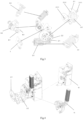
Fig. 1 shows a schematic perspective view of an operating mechanism suitable for a dual power transfer switch according to the present disclosure; -
Fig. 2 shows a schematic perspective view of an operating mechanism suitable for a dual power transfer switch according to the present disclosure, in which a main spindle holding mechanism module, a first closing energy releasing mechanism module and a second closing energy releasing mechanism module are removed; -
Fig. 3 shows an exploded perspective view of a part of the components inFigs. 1 and 2 ; -
Fig. 4 shows an electric energy storage mechanism module and a manual energy storage mechanism module suitable for an operating mechanism of a dual power transfer switch according to the present disclosure; -
Fig. 5 shows a schematic diagram of a first energy storage mechanism module suitable for an operating mechanism of a dual power transfer switch in a non-energy storage state according to the present disclosure; -
Fig. 6 shows a schematic diagram of a first energy storage mechanism module suitable for an operating mechanism of a dual power transfer switch in an energy storage state according to the present disclosure; -
Fig. 7 shows a schematic diagram of an internal driving structure of an operating mechanism suitable for a dual power transfer switch according to the present disclosure, in which a first main spindle mechanism module is in a first closing position; -
Fig. 8 shows that an action of the energy storage releasing mechanism module releases the holding of the energy storage holding mechanism module on the first opening spring, so that the first opening spring can be released; -
Fig. 9 shows a schematic diagram of an internal driving structure of an operating mechanism suitable for a dual power transfer switch according to the present disclosure, in which the first main spindle mechanism module is in a double-separation position; -
Fig. 10 shows a main spindle holding mechanism module suitable for an operating mechanism of a dual power transfer switch according to the present disclosure, which includes a first locking piece and a second locking piece; -
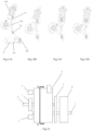
Figs. 11A to 11D show a schematic process diagram of an operating mechanism suitable for a dual power transfer switching from a double-separation position to a first closing position according to the present disclosure; -
Fig. 12 shows a schematic block diagram of an operating mechanism suitable for a dual power transfer switch according to the present disclosure, which has three stations; -
Fig. 13 shows a schematic sectional view ofFig. 12 along a section line A-A; -
Fig. 14 shows a schematic block diagram of an operating mechanism suitable for a dual power transfer switch according to the present disclosure, which has two stations; -
Fig. 15 shows a schematic sectional view ofFig. 14 along a section line A-A; -
Fig. 16 shows a schematic block diagram of an operating mechanism suitable for a dual power transfer switch, which has a first core frame and a second core frame; -
Fig. 17 shows a schematic sectional view ofFig. 16 along section line A-A. - In order to make the purpose, technical details and advantages of the technical solution of the present disclosure more clear, the technical solution of the embodiment of the present disclosure will be described clearly and completely with the accompanying drawings of specific embodiments of the present disclosure. Like reference numerals in the drawings represent like parts. It should be noted that the described embodiments are a part of the embodiment of the present disclosure, not the all embodiments. Based on the described embodiments of the present disclosure, all other embodiments obtained by ordinary skilled in the art without creative labor belong to the scope of protection of the present disclosure.
- Compared with the embodiments shown in the attached drawings, the feasible embodiments within the protection scope of the present disclosure may have fewer components, other components not shown in the attached drawings, different components, components arranged differently or components connected differently, etc. Furthermore, two or more components in the drawings may be implemented in a single component, or a single component shown in the drawings may be implemented as a plurality of separate components.
- Unless otherwise defined, technical terms or scientific terms used herein shall have their ordinary meanings as understood by people with ordinary skills in the field to which the present disclosure belongs. The words "first", "second" and similar words used in the specification and claims of the patent application of the present disclosure do not indicate any order, quantity or importance, but are only used to distinguish different components. When the number of parts is not specified, the number of parts can be one or more; Similarly, similar words such as "a" and "an" do not necessarily mean quantity limitation. Similar words such as "including" or "containing" mean that the element or object appearing before the word covers the element or object listed after the word and its equivalents, but does not exclude other elements or objects. Similar words such as "installation", "setting", "connection" or "connection" are not limited to physical or mechanical installation, setting and connection, but can include electrical installation, setting and connection, whether directly or indirectly. "Up", "Down", "Left" and "Right" are only used to indicate the relative orientation relationship when the equipment is used or the orientation relationship shown in the attached drawings. When the absolute position of the described object changes, the relative orientation relationship may also change accordingly.
- As illustrated by
Fig. 1 and Fig. 2 , anoperating mechanism 1 for a dual power transfer switch includes a first spring energystorage mechanism module 2, an energy storageholding mechanism module 3, an energy storage releasingmechanism module 4, a firsttransmission mechanism module 5 and a first mainspindle mechanism module 6. - The first spring energy
storage mechanism module 2 is able to store energy. - The energy storage
holding mechanism module 3 is able to act on the first spring energystorage mechanism module 2, so that the first spring energystorage mechanism module 2 can hold the stored energy. - The energy storage releasing
mechanism module 4 is able to act on the first spring energystorage mechanism module 2 through the energy storageholding mechanism module 3, so that the first spring energystorage mechanism module 2 can release the stored energy. - The energy released by the first spring energy
storage mechanism module 2 acts on the first mainspindle mechanism module 6 through the firsttransmission mechanism module 5, so that the first mainspindle mechanism module 6 is able to store energy first and then release energy, and then the first mainspindle mechanism module 6 moves between the first closing position and the second closing position. - The movement of the first main
spindle mechanism module 6 between the first closing position and the second closing position enables the dual power transfer switch coupled with the first mainspindle mechanism module 6 to switch between the first power supply and the second power supply. - As illustrated by
Figs. 1 and10 , theoperating mechanism 1 further includes a main spindleholding mechanism module 7, a first closing energy releasingmechanism module 8 and a second closing energy releasingmechanism module 9. - The main spindle
holding mechanism module 7 is able to act on the first mainspindle mechanism module 6, so that the first mainspindle mechanism module 6 can be locked in the double-separation position (as illustrated byFig. 10 ). - When the first closing energy releasing
mechanism module 8 acts on the main spindleholding mechanism module 7, so that the main spindleholding mechanism module 7 unlocks the first mainspindle mechanism module 6, the first mainspindle mechanism module 6 is able to move from the double-separation position to the first closing position, and then the first power supply is switched on. - When the second closing energy releasing
mechanism module 9 acts on the main spindleholding mechanism module 7, so that the main spindleholding mechanism module 7 unlocks the first mainspindle mechanism module 6, the first mainspindle mechanism module 6 is able to move from the double-separation position to the second closing position, and then the second power supply is switched on. - As illustrated by
Figs. 1, 2 and4 , the operating mechanism further includes an electric energystorage mechanism module 10 and/or a manual energystorage mechanism module 11. - The electric energy
storage mechanism module 10 and/or the manual energystorage mechanism module 11 act on the first spring energystorage mechanism module 2, so that the first spring energystorage mechanism module 2 stores energy. - As illustrated by
Fig. 12 , the operating mechanism includes afirst core frame 12 as a part of the overall frame of the operating mechanism. - As illustrated by
Fig. 13 , the first mainspindle mechanism module 6, the first spring energystorage mechanism module 2, the firsttransmission mechanism module 5 and the energy storageholding mechanism module 3 are accommodated in thefirst core frame 12. - As illustrated by
Fig. 12 , the electric energystorage mechanism module 10 and/or the manual energystorage mechanism module 11 are located at one side outside thefirst core frame 12, while the main spindleholding mechanism module 7, the first closing energy releasingmechanism module 8 and the second closing energy releasingmechanism module 9 are located at the other side outside thefirst core frame 12. - Of course, those skilled in the art can understand that the electric energy
storage mechanism module 10 and/or the manual energystorage mechanism module 11 are located on the other side outside thefirst core frame 12, while the main spindleholding mechanism module 7, the first closing energy releasingmechanism module 8 and the second closing energy releasingmechanism module 9 are located on the one side outside thefirst core frame 12. - Compared with
Fig. 12 andFig. 13 , as illustrated byFig. 14 to Fig. 15 , the main spindleholding mechanism module 7, the first closing energy releasingmechanism module 8 and the second closing energy releasingmechanism module 9 are removed, so that the operating mechanism is changed from three stations to two stations. - As illustrated by
Figs. 16 and17 , the operating mechanism includes at least one second core frame 13 (only one is shown inFig. 16 for clarity). Thesecond core frame 13 is a part of the overall frame of the operating mechanism. - The main spindle 6-1 of the first main
spindle mechanism module 6 and the energy storage shaft 2-1-1 of the first spring energystorage mechanism module 2 can penetrate through a plurality of second core frames. - Inside each
second core frame 13, a second main spindle mechanism module (not shown), a second spring energy storage mechanism module (not shown) and a second transmission mechanism module (not shown) are accommodated. - The second main spindle mechanism module, the second spring energy storage mechanism module and the second transmission mechanism module respectively have the same structure and operating state as the first main
spindle mechanism module 6, the first spring energystorage mechanism module 2 and the firsttransmission mechanism module 5. - The main spindle
holding mechanism module 7, the first closing energy releasingmechanism module 8 and the second closing energy releasingmechanism module 9 are located between thefirst core frame 12 and thesecond core frame 13 adjacent to thefirst core frame 12. - The rotation of the main spindle 6-1 of the first main
spindle mechanism module 6 is able to drive a corresponding movable contact of a corresponding dual power transfer switch coupled with the second main spindle mechanism module (not shown) to move between a first closing position and a second closing position, so that the corresponding dual power transfer switch is able to be switched between a first power supply and a second power supply, wherein the second main spindle mechanism module is provided with a second closing spring (not shown) which biases the second main spindle mechanism module to the first closing position and/or the second closing position. - The second spring energy storage mechanism module includes a second opening spring (not shown), which is connected to the manual
energy storage device 10 and/or the electricenergy storage device 11 to store energy for the second opening spring of the second spring energy storage mechanism module manually and/or electrically, and an output part of the second spring energy storage mechanism module is coupled to the second main spindle mechanism module through a second transmission mechanism module (not shown) for achieving an opening action. - The energy storage
holding mechanism module 3 acts on the second spring energy storage mechanism module through the energy storage shaft 2-1-1 of the first spring energystorage mechanism module 2 to keep locking the second spring energy storage mechanism module in a storage state; and the energy storage releasingmechanism module 4 acts on the energy storageholding mechanism module 3, so that the energy storageholding mechanism module 3 no longer keeps locking the second spring energy storage mechanism module when the energy storage releasingmechanism module 4 acts, so that the second spring energy storage mechanism module starts to release the stored energy; when the energy storageholding mechanism module 3 releases the second spring energy storage mechanism module, the energy released by the second spring energy storage mechanism module causes the second main spindle mechanism module to rotate through the second transmission mechanism module, so that the second main spindle mechanism module moves away from the first closing position or the second closing position. - As illustrated by
Fig. 3 , the first spring energystorage mechanism module 2 includes an energy storage shaft assembly 2-1, an energy storage actuating assembly 2-2 (serving as the output part of the first spring energy storage mechanism module 2), and a first opening spring 2-3. - The electric energy
storage mechanism module 10 and/or the manual energystorage mechanism module 11 are configured to drive the energy storage shaft assembly 2-1 to rotate. - The energy storage actuating assembly 2-2 is rotatably installed on the frame of the operating mechanism 1 (for example, through its pivot shaft 2-2-1), and one end of the energy storage actuating assembly 2-2 can be pivotally connected to the first opening spring 2-3.
- The rotation of the energy storage shaft assembly 2-1 causes the first opening spring 2-3 to store energy through the energy storage actuating assembly 2-2.
- The energy storage shaft assembly 2-1 includes an energy storage shaft 2-1-1 and an energy storage shaft cam 2-1-2 installed on the energy storage shaft 2-1-1 and taking the energy storage shaft 2-1-1 as the rotation axis.
- As illustrated by
Figs. 5 to 6 , the energy storage actuating assembly 2-2 is provided with an actuating assembly roller B; - When the electric energy
storage mechanism module 10 and/or the manual energystorage mechanism module 11 drive the energy storage shaft 2-1-1 to rotate (counterclockwise), the cam profile of the energy storage shaft cam 2-1-2 will push the actuating assembly roller B, and then drive the energy storage actuating assembly 2-2 to rotate (counterclockwise). - As illustrated by
Figs. 5 to 6 , the rotation of the energy storage actuating assembly 2-2 causes the first opening spring 2-3 to compress to store energy. - As illustrated by
Figs. 5 and 6 , the energy storageholding mechanism module 3 includes an energy storage holding lever 3-1 and a half shaft 3-2. - The energy storage holding lever 3-1 is pivotally installed on the frame of the
operating mechanism 1, for example, through its pivot shaft 3-1-3. - The energy storage holding lever 3-1 includes a first end 3-1-1 and a second end 3-1-2.
- The storage shaft cam 2-1-2 is provided with a main spindle cam roller A.
- The first end 3-1-1 of the energy storage holding lever 3-1 is able to act on the main spindle cam roller A.
- The second end 3-1-2 of the energy storage holding lever 3-1 is able to act on the half shaft 3-2.
- As illustrated by
Figs. 5 and 6 , the half shaft 3-2 is rotatably connected to the frame of theoperating mechanism 1. - A semicircular part is arranged on the half shaft 3-2, and the rotation of the half shaft 3-2 can block and give way to the rotation of the energy storage holding lever 3-1.
- When the rotation of the half shaft 3-2 causes the semicircular part to give way to the second end 3-1-2 of the energy storage holding lever 3-1, the second end 3-1-2 of the energy storage holding lever 3-1 can rotatably pass through the semicircular part.
- When the semicircular part blocks the second end 3-1-2 of the energy storage holding lever 3-1, the rotation of the second end 3-1-2 of the energy storage holding lever 3-1 is blocked by the semicircular part.
- As illustrated by
Figs. 5 and 6 , the energy storageholding mechanism module 3 further includes a shift lever 3-3 (as an input part of the energy storage holding mechanism module). - The shift lever 3-3 is rotatably installed on the frame of the
operating mechanism 1, for example, through its pivot shaft 3-3-1. - The shift lever 3-3 is able to act on the half shaft 3-2, so that the half shaft 3-2 can block or give way to the second end 3-1 -2 of the energy storage holding lever 3-1.
- After the first opening spring 2-3 completes the compression energy storage (in
Fig. 6 , the first opening spring 2-3 is at the under-dead-center position), the main spindle cam roller A abuts against the first end 3-1-1 of the energy storage holding lever 3-1, the actuating assembly roller B abuts against the cam profile of the energy storage shaft cam 2-1-2, and the semicircular part blocks the second end 3-1-2 of the energy storage holding lever 3-1. The first end 3-1-1 of the energy storage holding lever 3-1 blocks the rotational moment acting on the energy storage shaft cam 2-1-2 due to the actuating assembly roller B, so that the energy storage shaft cam 2-1-2 will not rotate (the energy storage actuating assembly 2-2 will not rotate either), and the first opening spring 2-3 will not be extended to release energy. - The energy storage releasing
mechanism module 4 includes an energy storage releasing electromagnetic driver having a releasing electromagnetic coil 4-1 and an electromagnetic coil movable iron core 4-2 (as an output part of the energy storage releasing mechanism module 4). - As illustrated by
Fig. 6 to Fig. 8 , in order to release the energy of the first opening spring 2-3, the electromagnetic coil 4-1 is energized, so that the electromagnetic coil movable iron core 4-2 acts on the shift lever 3-3, and the shift lever 3-3 is able to act on the half shaft 3-2, so that the semicircular part of the half shaft 3-2 can rotate without blocking the second end 3-1-2 of the energy storage holding lever 3-1. The rotation of the energy storage holding lever 3-1 causes its first end 3-1-1 not to block the main spindle cam roller A or the rotating moment acting on the energy storage shaft cam 2-1-2 due to the actuating assembly roller B, so that the energy storage holding lever 3-1 does not limit the expansion and energy release of the first opening spring 2-3, which is able to drive the energy storage actuating assembly 2-2 to rotate, and the actuating assembly roller B moves into a concave part of the gear profile of the storage shaft cam 2-1-2 (as shown inFig. 8 ). - The energy storage releasing
mechanism module 4 can be arranged at any side or above or below the energy storageholding mechanism module 3, and the output part of the energy storage releasingmechanism module 4 keeps coupling with the input part of the energy storageholding mechanism module 3, so as to drive and unlock the energy storageholding mechanism module 3 when the energy storage releasingmechanism module 4 acts. - The energy released by the expansion of the first opening spring 2-3 drives the energy storage actuating assembly 2-2 to move.
- The movement of the energy storage actuating assembly 2-2 causes the first main
spindle mechanism module 6 to rotate from the first closing position or the second closing position to the double-separation position through the transmission mechanism module. - As illustrated by
Fig. 10 , the first mainspindle mechanism module 6 includes a main spindle 6-1, a main spindle crank arm 6-2 and a main spindle lock tongue 6-3 fixedly installed on the main spindle 6-1. - The main spindle
holding mechanism module 7 includes a first locking piece 7-1 and a second locking piece 7-2. - Through the relative movement between the first locking piece 7-1 and the second locking piece 7-2, an openable and closable locking port 7-3 is formed between the first locking end of the first locking piece 7-1 and the second locking end of the second locking piece 7-2.
- During the movement of the first main
spindle mechanism module 6 between the first closing position and the second closing position, the locking port 7-3 can receive the main spindle lock tongue 6-3 and keep the main spindle lock tongue 6-3 between the first locking end of the first locking piece 7-1 and the second locking end of the second locking piece 7-2, so as to lock the first mainspindle mechanism module 6 in a double-separation position between the first closing position and the second closing position. - As illustrated by
Fig. 7 , the main spindle crank arm 6-2 includes a first driven part 6-2-1 and a second driven part 6-2-2, both of which may be formed, for example, as a protrusions or the like at appropriate positions of the main spindle crank arm 6-2 for being driven by thetransmission mechanism module 5 according to the present disclosure. - The first
transmission mechanism module 5 includes a driving piece 5-1, which is able to move between an initial position and a driving position, and includes a first driving part 5-1-1 and a second driving part 5-1-2. - As illustrated by
Fig. 7 , when the first mainspindle mechanism module 6 is in the first closing position, the first driving part 5-1-1 drives the first driven part 6-2-1 to move the first mainspindle mechanism module 6 from the first closing position to the second closing position by the movement of the driving piece 5-1 from the initial position to the driving position. - When the first main
spindle mechanism module 6 is in the second closing position, the second driving part 5-1-2 drives the second driven part 6-2-2 by the movement of the driving piece 5-1 from the initial position to the driving position, so that the first mainspindle mechanism module 6 moves from the second closing position to the first closing position. - According to the present disclosure, the positions of the first driven part 6-2-1 and the second driven part 6-2-2 are changed correspondingly because the positions of the main shaft crank arm 6-2 at the first closing position and the second closing position are different, so the main shaft crank arm 6-2 can be realized by reasonably setting the positions of the first driven part 6-2-1 and the second driven part 6-2-2. When the first main
spindle mechanism module 6 is in the first closing position, the first driven part 6-2-1 and the first driving part 5-1-1 are close to each other and the second driven part 6-2-2 and the second driving part 5-1-2 are far away from each other. - When the first main
spindle mechanism module 6 is in the second closing position, the first driven part 6-2-1 and the first driving part 5-1-1 are far away from each other and the second driven part 6-2-2 and the second driving part 5-1-2 are close to each other. - With this arrangement, when the main spindle crank arm 6-2 is at any position, the driving piece 5-1 is able to drive the corresponding driven part only by one-way movement towards the driving position, so that the main spindle crank arm 6-2 moves towards another position.
- Compared with the complicated existing art that two sets of driving devices are respectively arranged for the movement towards two positions, or a complex bidirectional driving mechanism module is arranged in one set of driving device, the invention can realize the two-position driving of the main spindle crank arm 6-2 by only arranging a single driving piece 5-1 capable of unidirectional movement.
- It should be understood that the "unidirectional movement" here refers to that the driving direction of the driving piece 5-1 is unidirectional, but the driving piece 5-1 can still return to the initial position.
- The driving piece 5-1 is set such that after the first driving part 5-1-1 drives the first driven part 6-2-1 and reaches the driving position of the driving part 5-1, the main
spindle mechanism module 6 is locked in the double-separation position, and with the unlocking action of the second closing energy releasingmechanism module 9, the mainspindle mechanism module 6 continues to move towards the second closing position, and the second driven part 6-2-2 drives the second driving part 5-1-2. After the second driving part 5-1-2 drives the second driven part 6-2-2 and reaches the driving position of the driver 5-1, the mainspindle mechanism module 6 continues to move towards the first closing position with the unlocking action of the first closing energy releasingmechanism module 8, and the first driven part 6-2-1 exerts a force on the first driving part 5-1-1 to urge the driving piece 5-1 to return to the initial position. - The first driven part 6-2-1 and/or the second driven part 6-2-2 includes a roller. By setting the rollers, the interaction between the first driving part and the second driving part and the first driven part and second driven part can be improved, the friction can be reduced, and the movement between them can be smoother.
- The first main
spindle mechanism module 6 also includes a first closing spring 6-4. - When the first driving part 5-1-1 drives the first driven part 6-2-1, the first closing spring 6-4 stores energy. With the unlocking action of the second closing energy releasing
mechanism module 9, after the first driving part 5-1-1 is separated from the first driven part 6-2-1, the first closing spring 6-4 releases the stored energy to move the first mainspindle mechanism module 6 to the second closing position. - When the second driving part 5-1-2 drives the second driven part 6-2-2, the first closing spring 6-4 stores energy. With the unlocking action of the first closing energy releasing
mechanism module 8, after the second driving part 5-1-2 is separated from the second driven part 6-2-2, the first closing spring 6-4 releases the stored energy to move the first mainspindle mechanism module 6 to the first closing position. - As illustrated by
Fig. 9 , the first closing spring 6-4 is arranged as a compression spring and pivotally connected with one end of the main spindle crank arm 6-2, and when the driving piece 5-1 reaches the driving position, the compression spring is at the dead center position. - As illustrated by
Fig. 7 , the driving piece 5-1 has a pivot 5-2, and the driving piece 5-1 rotates around the pivot 5-2 between the initial position and the driving position. - The driving piece 5-1 is formed as a plate-like piece, a part of its outer contour is used as the first driving part 5-1-1, and another part of its outer contour is used as the second driving part 5-1-2.
- The energy storage actuating assembly 2-2 is able to move between an initial position and an actuating position,
- The energy storage actuating assembly 2-2 urges the driving piece 5-1 to move from the initial position to the driving position in the process of moving from the initial position to the actuating position.
- The first
transmission mechanism module 5 further includes a transmission piece 5-3, which is pivotally connected with the driving piece 5-1 through a pivot 5-4 and has a first end 5-3-1 and a second end 5-3-2 at both sides of the pivot 5-4. - The first end 5-3-1 is movably arranged in a chute 5-1-3 on the driving piece 5-1 , and the second end 5-3-2 is able to move along the first contour 2-2-2 of the energy storage actuating assembly 2-2 during the movement of the energy storage actuating assembly 2-2 from the initial position to the actuating position, so that the energy storage actuating assembly 2-2 urges the driving member 5-3 to move from the initial position to the driving position through the transmission piece 5-3.
- The driving piece 5-1 includes a return spring (not shown) that can return the driving piece 5-1 from the driving position to the initial position, and the return spring is connected to the first end 5-3-1 of the transmission piece 5-3.
- During the movement of the energy storage actuating assembly 2-2 from the initial position to the actuating position, the first contour 2-2-2 applies a first torque to the second end 5-3-2 around the pivot 5-4 of the transmission piece 5-3, so that the first end 5-3-1 of the transmission piece 5-3 remains to abut against the end of the chute 5-1-3.
- As illustrated by
Fig. 7 , the energy storage actuating assembly 2-2 further includes a second profile 2-2-3 that is continuous with the first profile 2-2-2. - After the energy storage actuating assembly 2-2 reaches the actuating position, the second end 5-3-2 of the driving piece 5-1 disengages from the first profile 2-2-2 of the energy storage actuating assembly 2-2 and moves to the second profile 2-2-3.
- When the second end 5-3-2 of the transmission piece 5-3 moves to the part of the second profile 2-2-3 that is connected with the first profile 2-2-2, the connected part applies a second torque to the second end 5-3-2 around the pivot 5-4 of the transmission piece 5-3, so that the second end 5-3-2 of the transmission piece 5-3 moves along the second profile 2-2-3, and the second torque is opposite to the first torque.
- During the return of the energy storage actuating assembly 2-2 from the actuating position to the initial position, the second profile 2-2-3 of the energy storage actuating assembly 2-2 moves away from the second end 5-3-2 of the transmission piece 5-3.
- After the second profile 2-2-3 of the energy storage actuating assembly 2-2 moves away from the second end 5-3-2 of the transmission piece 5-3, the return spring continues to contract and rotate the transmission piece 5-3 around its pivot 5-4, so that the second end 5-3-2 of the transmission piece 5-3 returns to the first profile 2-2-2 of the energy storage actuating assembly 2-2.
- The energy storage shaft assembly 2-1 can release energy storage to the energy storage actuating assembly 2-2 to move the energy storage actuating assembly 2-2 from the initial position to the actuating position.
- As illustrated by
Fig. 5 , the first opening spring 2-3 includes a fixed pivot end 2-3-1 and a movable pivot end 2-3-2 pivotally connected to the energy storage actuating assembly 2-2. - As illustrated by
Fig. 6 , the electric energystorage mechanism module 10 and/or the manual energystorage mechanism module 11 drive the energy storage shaft 2-1-1 to rotate counterclockwise (store energy), the energy storage shaft cam 2-1-2 rotates, and its cam surface pushes the actuating assembly roller B, and the actuating assembly roller B drives the energy storage actuating assembly 2-2 to rotates counterclockwise (from the actuating position to the initial position), and the energy storage actuating assembly 2-2 compress the first opening spring 2-3 to store energy. - During the movement of the first main
spindle mechanism module 6 from the first closing position to the second closing position, the main spindle lock tongue 6-3 applies a first opening action to the first locking piece 7-1 to completely open the locking port 7-3. - During the movement of the first main
spindle mechanism module 6 from the second closing position to the first closing position, the main spindle lock tongue 6-3 applies a second opening action to the second locking piece 7-2 to completely open the locking port 7-3. - During the first opening action, after the first locking piece 7-1 moves to its limit position, the first locking piece 7-1 causes the main spindle lock tongue 6-3 to make the first return action towards the locking position.
- During the second opening action, after the second locking piece 7-2 moves to its limit position, the second locking piece 7-2 causes the main spindle lock tongue 6-3 to make a second return action towards the locking position.
- The first locking piece 7-1 has a first biasing mechanism module 7-1-1, and the first biasing mechanism module 7-1-1 applies a force to the first locking piece 7-1 that tends to make the first locking piece 7-1 close the locking port 7-3.
- The second locking piece 7-2 has a second biasing mechanism module 7-2-1, and the second biasing mechanism module 7-2-1 applies a force to the second locking piece 7-2 that tends to make the second locking piece 7-2 close the locking port 7-3.
- The first locking piece 7-1 is arranged to pivot around a first pivot 7-1-2, and the torque applied to the first locking end by the main spindle lock tongue 6-3 is in the same direction as that applied to the first locking piece 7-1 by the first biasing mechanism module 7-1-1 of the first locking piece 7-1.
- The second locking piece 7-2 is arranged to pivot around a second pivot 7-2-2, and the torque applied to the second locking end by the main spindle lock tongue 6-3 is in the same direction as that applied to the second locking piece 7-2 by the second biasing mechanism module 7-2-1 of the second locking piece 7-2.
- The first locking end has an arc surface 7-1-3, the center of which is not concentric with the rotation center of the first pivot 7-1-2 and/or the second locking end has an arc surface 7-2-3, and the center of which is not concentric with the rotation center of the second pivot 7-2-2.
- The first locking piece 7-1 includes a first free end; the second locking member 7-2 includes a second free end. The first free end and the second free end serve as input parts of the main spindle
holding mechanism module 7. - As illustrated by
Fig. 11 , the first closing energy releasingmechanism module 8 is configured as a first electromagnetic driver, which has a first electromagnetic coil 8-1 and a first movable iron core 8-2 (as the output part of the first closing energy releasing mechanism module 8) that is able to actuate the second free end of the second locking piece 7-2. The movement of the first movable iron core 8-2 causes the second locking piece 7-2 to move away from the main shaft lock tongue 6-3 to give way. Driven by the first locking piece 7-1, the main spindle lock tongue 6-3 causes the first closing spring 6-4 pass through the dead point, and the first closing spring 6-4 releases energy, so that the mainspindle mechanism module 6 rotates from the double-separation position to the first closing position, and the second locking piece 7-2 is reset. - The first electromagnetic driver can be arranged at the lower side (as illustrated by
Fig. 11 ) or a lateral side (left side or right side, not shown) of the second locking piece 7-2, so that the movement of the first movable iron core 8-2 enables the second locking piece 7-2 to move away from the main spindle lock tongue 6-3 to give way. - As illustrated by
Fig. 1 , the second closing energy releasingmechanism module 9 is configured as a second electromagnetic driver, which has a second electromagnetic coil 9-1 and a second movable iron core 9-2 (as the output part of the second closing energy releasing mechanism module 9) that is able to actuate the first free end of the first locking piece 7-1, and the movement of the second movable iron core 9-2 causes the first locking piece 7-1 to move away from the main spindle lock tongue 6-3 to give way. Driven by the second locking piece 7-2, the main spindle lock tongue 6-3 causes the first closing spring 6-4 to pass through the dead point, and the first closing spring 6-4 releases energy, so that the mainspindle mechanism module 6 rotates from the double-separation position to the second closing position, and the first locking piece 7-1 is reset. - The second electromagnetic driver can be arranged at the upper side (as illustrated by
Fig. 1 ) or a lateral side (left side or right, not shown) of the first locking piece 7-1, so that the movement of the second movable iron core 9-2 enables the first locking piece 7-1 move away from the main spindle lock tongue 6-3 to give way. - That is to say, the first closing energy releasing
mechanism module 8 and the second closing energy releasingmechanism module 9 can be arranged at any side or above or below the main spindleholding mechanism module 7, while the output parts of the first closing energy releasingmechanism module 8 and the second closing energy releasingmechanism module 9 keep matching with the input part of the main spindleholding mechanism module 7. - According to the above embodiments of the present disclosure, the principle and operation flow of the operating mechanism with three stations are as follows:
- 1. Energy storage of the first opening spring: electric energy storage mechanism module and/or manual energy storage mechanism module → first opening spring energy storage (+energy storage holding mechanism module locks the first opening spring);
- 2. Opening: the energy storage releasing mechanism module acts → the energy storage holding mechanism module unlocks the first opening spring → the first opening spring releases energy → the first transmission mechanism module → the main spindle of the first main spindle mechanism module (+the first closing spring stores energy + the main spindle holding mechanism module locks the main spindle of the first main spindle mechanism module) → the breaking unit opens (double-separation position);
- 3. Closing of the first power supply S1: the first closing energy releasing mechanism module acts → the main spindle holding mechanism module trips to S1 → the first closing spring releases energy → the main spindle of the first main spindle mechanism module rotates to S1 → the breaking unit closes (the first closing position); or
- Closing of the second power supply S2: the second closing energy releasing mechanism module acts → the main spindle holding mechanism module trips to S2 → the first closing spring releases energy → the main spindle of the first main spindle mechanism module rotates to S2 → the breaking unit closes (the second closing position).
- According to the above-mentioned embodiments of the present disclosure, the main spindle holding mechanism module, the first closing energy releasing mechanism module and the second closing energy releasing mechanism module can be removed, and the three-station operating mechanism can be changed into two-station operating mechanism. The principle and operation flow are as provided follows (taking the first power supply S1 closing to the second power supply S2 closing as an example):
- 1. Energy storage of the first opening spring: electric energy storage mechanism module and/or manual energy storage mechanism module → first opening spring energy storage (+energy storage holding mechanism module locks the first opening spring);
- 2. Conversion: the energy storage releasing mechanism module acts → the energy storage holding mechanism module unlocks the first opening spring → the first opening spring releases energy → the first transmission mechanism module → the main spindle of the first main spindle mechanism module (+the first closing spring directly releases energy after storing energy and drives the main spindle of the first main spindle mechanism module to continue rotating) → the breaking unit switches from S1 to S2 (from the first closing position to the second closing position).
- According to the above embodiment of the present disclosure, the first closing spring has two energy releasing positions in different directions (corresponding to the first closing position and the second closing position respectively) and a dead point position (double-separation position), and the dead point position is maintained by a set of "spindle holding mechanism module" and two sets of "closing energy releasing mechanism module" and the releasing directions are controlled. Therefore, in the technical solution, a group of first closing springs can correspond to three working positions.
- According to the above contents of the present disclosure, the first opening spring is able to store energy in advance, which has greater energy. When the energy is released, it not only drives the opening unit to open, but also stores energy for the first closing spring. This process is fast, so after opening, it can be quickly closed, which is beneficial to the rapid conversion of the dual power transfer switch.
- According to another embodiment of the present disclosure, a dual power transfer switch is provided, the dual power transfer switch includes the operating mechanism as described above.
- According to the modular design of the present disclosure, the layout of the operating mechanism can be flexibly configured to adapt to more products, for example, three working positions can be changed into two working positions, and the positions of the main spindle holding mechanism module/the first closing energy releasing mechanism module/the second closing energy releasing mechanism module/the energy storage releasing mechanism module can be flexibly arranged.
- According to the above contents of the present disclosure, it is possible to expand the original single-core frame structure into a multi-core frame structure (namely, two sets of transmission mechanism modules/energy storage mechanism modules/main spindle mechanism modules), and only one set of corresponding holding mechanism module and corresponding releasing mechanism module (main spindle holding mechanism module/first closing energy releasing mechanism module/second closing energy releasing mechanism module/energy storage releasing mechanism module/energy storage holding mechanism module) is needed. The main spindle of the first main spindle mechanism module and the energy storage shaft of the first energy storage mechanism module can penetrate through a plurality of core frames, so as to ensure the synchronization of movement and control. Through such layout changes, it can be easily upgraded to a mechanism module with greater operating power, such as a three-station TSE with a rated current of 4000A.
- The foregoing disclosure provides illustration and description, but is not intended to be exhaustive or to limit the embodiments to the precise forms disclosed. Modifications and variations are possible in light of the above disclosure, or may be acquired from practice of the embodiments.
- Even if specific combinations of features are recited in the claims and/or disclosed in the specification, these combinations are not intended to limit the present disclosure of various embodiments. In fact, many of these features can be combined in ways not specifically recited in the claims and/or not specifically disclosed in the specification. Although each dependent claim listed below may directly depend on only one claim, the present disclosure of various embodiments includes each dependent claim in combination with every other claim in the claim set.
Claims (9)
- An operating mechanism (1) for a dual power transfer switch, wherein the operating mechanism (1) comprises:a first main spindle mechanism module (6) comprising a rotatable main spindle (6-1), wherein a rotation of the main spindle (6-1) is able to drive a movable contact of the dual power transfer switch coupled with the first main spindle mechanism module (6) to move between a first closing position and a second closing position, so that the dual power transfer switch is able to be switched between a first power supply and a second power supply, the first main spindle mechanism module (6) is provided with a first closing spring (6-4), the first closing spring (6-4) biases the first main spindle mechanism module (6) to the first closing position and/or the second closing position;a first spring energy storage mechanism module (2), comprising a first opening spring (2-3), wherein the first opening spring (2-3) is connected to a manual energy storage device (10) and/or an electric energy storage device (11) to store energy for the first opening spring (2-3) of the first spring energy storage mechanism module (2) manually and/or electrically, and an output part of the first spring energy storage mechanism module (2) is connected to the first main spindle mechanism module (6), and used to achieve an opening operation;an energy storage holding mechanism module (3), acting on the first spring energy storage mechanism module (2) to keep locking the first spring energy storage mechanism module (2) in a storage state; andan energy storage releasing mechanism module (4), acting on the energy storage holding mechanism module (3), wherein, upon the energy storage releasing mechanism module (4) acting, the energy storage holding mechanism module (3) no longer keeps locking the first spring energy storage mechanism module (2), so that the first spring energy storage mechanism module (2) starts to release stored energy;wherein, upon the energy storage holding mechanism module (3) releasing the first spring energy storage mechanism module (2), energy released by the first spring energy storage mechanism module (2) causes the first main spindle mechanism module (6) to rotate through a first transmission mechanism module (5), so that the first main spindle mechanism module (6) moves away from the first closing position or the second closing position.
- The operating mechanism according to claim 1, wherein the operating mechanism (1) further comprises:a main spindle holding mechanism module (7) capable of acting on the first main spindle mechanism module (6), so that the first main spindle mechanism module (6) is able to be locked in a double-separation position;a first closing energy releasing mechanism module (8), acting on the main spindle holding mechanism module (7) so that the main spindle holding mechanism module (7) unlocks the first main spindle mechanism module (6) in a direction to the first closing position, so that the first main spindle mechanism module (6) is able to move from the double-separation position to the first closing position, so that the first power supply is switched on;a second closing energy releasing mechanism module (9), acting on the main spindle holding mechanism module (7) so that the main spindle holding mechanism module (7) unlocks the first main spindle mechanism module (6) in a direction to the second closing position, so that the first main spindle mechanism module (6) is able to move from the double-separation position to the second closing position, so that the second power supply is switched on.
- The operating mechanism according to claim 2, whereinthe operating mechanism comprises a first core frame (12);the first main spindle mechanism module (6), the first spring energy storage mechanism module (2), the first transmission mechanism module (5) and the energy storage holding mechanism module (3) are installed in the first core frame (12);the main spindle (6-1) of the first main spindle mechanism module (6) laterally passes through the first core frame (12) and is rotatably installed on the first core frame (12);the first spring energy storage mechanism module (2) comprises an energy storage shaft (2-1-1), the energy storage shaft (2-1-1) is coupled to the first opening spring (2-3), so that a rotation of the energy storage shaft (2-2-1) is able to store energy for the first opening spring (2-3), the electric energy storage mechanism module (10) and/or the manual energy storage mechanism module (11) is sleeved on the energy storage shaft (2-1-1), so as to drive the energy storage shaft (2-2-1) to rotate;the energy storage shaft (2-2-1) is arranged in parallel with the main spindle (6-1) of the first main spindle mechanism module (6), laterally passes through the first core frame (12) and is rotatably installed on the first core frame (12);the electric energy storage mechanism module (10) and/or the manual energy storage mechanism module (11) are located at a first side outside the first core frame (12); the main spindle holding mechanism module (7), the first closing energy releasing mechanism module (8) and the second closing energy releasing mechanism module (9) are located at a second side outside the first core frame (12) opposite to the first side;or, the electric energy storage mechanism module (10) and/or the manual energy storage mechanism module (11) are located at the second side outside the first core frame (12); the main spindle holding mechanism module (7), the first closing energy releasing mechanism module (8) and the second closing energy releasing mechanism module (9) are located at the first side outside the first core frame (12).
- The operating mechanism according to claim 3, whereinthe operating mechanism also comprises at least one second core frame (13);the main spindle (6-1) of the first main spindle mechanism module (6) and the energy storage shaft (2-1-1) of the first spring energy storage mechanism module (2) laterally penetrate the at least one second core frame (13);a second main spindle mechanism module (6), a second spring energy storage mechanism module (2) and a second transmission mechanism module (5) are correspondingly installed in each of the at least one second core frame (13), the second main spindle mechanism module and the first main spindle mechanism module (6) share a same main spindle (6-1), and the second spring energy storage mechanism module and the first spring energy storage mechanism module (2) share a same energy storage shaft (2-2-1).
- The operating mechanism according to claim 3, wherein
the energy storage releasing mechanism module (4) is arranged at any side or above or below the energy storage holding mechanism module (3), and the output part of the energy storage releasing mechanism module (4) keeps coupling with an input part of the energy storage holding mechanism module (3) so as to drive and unlock the energy storage holding mechanism module (3) upon the energy storage releasing mechanism module (4) acting. - The operating mechanism according to claim 3, wherein
the first closing energy releasing mechanism module (8) and the second closing energy releasing mechanism module (9) are arranged at any side or above or below the main spindle holding mechanism module (7), and output parts of the first closing energy releasing mechanism module (8) and the second closing energy releasing mechanism module (9) are coupled with an input part of the main spindle holding mechanism module (7). - The operating mechanism according to claim 4, wherein
the main spindle holding mechanism module (7), the first closing energy releasing mechanism module (8) and the second closing energy releasing mechanism module (9) are arranged between the first core frame (12) and the second core frame (13) adjacent to the first core frame (12). - The operating mechanism according to claim 4, whereinthe rotation of the main spindle (6-1) of the first main spindle mechanism module (6) is able to drive a corresponding movable contact of a corresponding dual power transfer switch coupled with the second main spindle mechanism module to move between a first closing position and a second closing position, so that the corresponding dual power transfer switch is able to be switched between a first power supply and a second power supply, wherein the second main spindle mechanism module is provided with a second closing spring, and the second closing spring biases the second main spindle mechanism module to the first closing position and/or the second closing position;the second spring energy storage mechanism module comprises a second opening spring, the second opening spring is connected to the manual energy storage device (10) and/or the electric energy storage device (11) to store energy for the second opening spring of the second spring energy storage mechanism module manually and/or electrically, and an output part of the second spring energy storage mechanism module is coupled to the second main spindle mechanism module through a second transmission mechanism module for achieving an opening operation;the energy storage holding mechanism module (3) acts on the second spring energy storage mechanism module through the energy storage shaft (2-1-1) to keep locking the second spring energy storage mechanism module in a storage state; andthe energy storage releasing mechanism module (4) acts on the energy storage holding mechanism module (3), and upon the energy storage releasing mechanism module (4) acting, the energy storage holding mechanism module (3) no longer keeps locking the second spring energy storage mechanism module, so that the second spring energy storage mechanism module starts to release stored energy;wherein, upon the energy storage holding mechanism module (3) releasing the second spring energy storage mechanism module, energy released by the second spring energy storage mechanism module causes the second main spindle mechanism module to rotate through the second transmission mechanism module, so that the second main spindle mechanism module moves away from the first closing position or the second closing position.
- A dual power transfer switch, wherein the dual power transfer switch comprises the operating mechanism according to any one of claims 1 to 8.
Applications Claiming Priority (1)
| Application Number | Priority Date | Filing Date | Title |
|---|---|---|---|
| CN202311076603.5A CN119517649A (en) | 2023-08-24 | 2023-08-24 | Operating mechanism for dual power transfer switch and dual power transfer switch |
Publications (1)
| Publication Number | Publication Date |
|---|---|
| EP4513521A1 true EP4513521A1 (en) | 2025-02-26 |
Family
ID=92583282
Family Applications (1)
| Application Number | Title | Priority Date | Filing Date |
|---|---|---|---|
| EP24306275.9A Pending EP4513521A1 (en) | 2023-08-24 | 2024-07-29 | Operating mechanism for dual power transfer switch and dual power transfer switch |
Country Status (2)
| Country | Link |
|---|---|
| EP (1) | EP4513521A1 (en) |
| CN (1) | CN119517649A (en) |
Citations (4)
| Publication number | Priority date | Publication date | Assignee | Title |
|---|---|---|---|---|
| EP0279045A2 (en) * | 1987-01-17 | 1988-08-24 | AEG Sachsenwerk GmbH | Universal drive |
| US6072136A (en) * | 1998-05-07 | 2000-06-06 | Eaton Corporation | Electrical switching apparatus with modular operating mechanism for mounting and controlling large compression close spring |
| US6177641B1 (en) * | 1998-04-17 | 2001-01-23 | Schneider Electric Sa | Plug-in circuit breaker discharge and disengagement energy storage control device used during extraction of breaker |
| CN117198779A (en) * | 2022-05-30 | 2023-12-08 | 施耐德电器工业公司 | Drive system for dual power transfer switch and dual power transfer switch |
-
2023
- 2023-08-24 CN CN202311076603.5A patent/CN119517649A/en active Pending
-
2024
- 2024-07-29 EP EP24306275.9A patent/EP4513521A1/en active Pending
Patent Citations (4)
| Publication number | Priority date | Publication date | Assignee | Title |
|---|---|---|---|---|
| EP0279045A2 (en) * | 1987-01-17 | 1988-08-24 | AEG Sachsenwerk GmbH | Universal drive |
| US6177641B1 (en) * | 1998-04-17 | 2001-01-23 | Schneider Electric Sa | Plug-in circuit breaker discharge and disengagement energy storage control device used during extraction of breaker |
| US6072136A (en) * | 1998-05-07 | 2000-06-06 | Eaton Corporation | Electrical switching apparatus with modular operating mechanism for mounting and controlling large compression close spring |
| CN117198779A (en) * | 2022-05-30 | 2023-12-08 | 施耐德电器工业公司 | Drive system for dual power transfer switch and dual power transfer switch |
Also Published As
| Publication number | Publication date |
|---|---|
| CN119517649A (en) | 2025-02-25 |
Similar Documents
| Publication | Publication Date | Title |
|---|---|---|
| RU2127924C1 (en) | Remote-control switch | |
| US6184483B1 (en) | Plug-in circuit breaker comprising an operating lever for opening and closing of poles | |
| US6382687B1 (en) | Power-closing motor-vehicle door latch | |
| CA1231745A (en) | Control device of an electric circuit breaker | |
| CZ295785B6 (en) | Device for controlling discharge and release of power accumulating apparatus during pulling out of plug-in current switch | |
| CN107068503A (en) | A kind of automatic division brake control device and its a kind of breaker | |
| JP2002208333A (en) | Auxiliary closing mechanism and drive mechanism for electric switchgear | |
| CN113113245B (en) | A split type on-load tap-changer | |
| CN115596298B (en) | Ice breaking mechanism for automobile door lock | |
| HK128794A (en) | Locking mechanism for a current-limiting contactor | |
| JPS6347095B2 (en) | ||
| CN1268760A (en) | Mechanism for operating three position switch e. g. off/star/delta | |
| CN119517649A (en) | Operating mechanism for dual power transfer switch and dual power transfer switch | |
| CN202332707U (en) | Single-module operating mechanism of vacuum circuit breaker | |
| CN115148557A (en) | Operating system of switch | |
| CN205487987U (en) | Operation mechanism of small breaker | |
| RU2110103C1 (en) | Spring mechanism of switch | |
| CN113168976A (en) | Transmission device for on-load tap-changer | |
| CN116130310A (en) | External electric operating device and breaker using same | |
| CN212365848U (en) | A kind of ring network cabinet manual opening and closing device | |
| CN210530547U (en) | Electric suction lock | |
| GB1572102A (en) | Locking device for vehicle doors | |
| CN211196183U (en) | Driver controller with interlocking function | |
| CN211287088U (en) | Door lock and lock cylinder mechanical unlocking mechanism thereof | |
| CN216957786U (en) | Two-way change-over switch and dual power supply system |
Legal Events
| Date | Code | Title | Description |
|---|---|---|---|
| PUAI | Public reference made under article 153(3) epc to a published international application that has entered the european phase |
Free format text: ORIGINAL CODE: 0009012 |
|
| STAA | Information on the status of an ep patent application or granted ep patent |
Free format text: STATUS: THE APPLICATION HAS BEEN PUBLISHED |
|
| AK | Designated contracting states |
Kind code of ref document: A1 Designated state(s): AL AT BE BG CH CY CZ DE DK EE ES FI FR GB GR HR HU IE IS IT LI LT LU LV MC ME MK MT NL NO PL PT RO RS SE SI SK SM TR |
|
| STAA | Information on the status of an ep patent application or granted ep patent |
Free format text: STATUS: REQUEST FOR EXAMINATION WAS MADE |
|
| 17P | Request for examination filed |
Effective date: 20250731 |
|
| STAA | Information on the status of an ep patent application or granted ep patent |
Free format text: STATUS: EXAMINATION IS IN PROGRESS |
|
| 17Q | First examination report despatched |
Effective date: 20260126 |