EP4513458A2 - Loose item management systems and methods for amusement park rides - Google Patents
Loose item management systems and methods for amusement park rides Download PDFInfo
- Publication number
- EP4513458A2 EP4513458A2 EP25150209.2A EP25150209A EP4513458A2 EP 4513458 A2 EP4513458 A2 EP 4513458A2 EP 25150209 A EP25150209 A EP 25150209A EP 4513458 A2 EP4513458 A2 EP 4513458A2
- Authority
- EP
- European Patent Office
- Prior art keywords
- lock
- rider
- portable locker
- pouch
- ride
- Prior art date
- Legal status (The legal status is an assumption and is not a legal conclusion. Google has not performed a legal analysis and makes no representation as to the accuracy of the status listed.)
- Pending
Links
Images








Classifications
-
- A—HUMAN NECESSITIES
- A45—HAND OR TRAVELLING ARTICLES
- A45C—PURSES; LUGGAGE; HAND CARRIED BAGS
- A45C13/00—Details; Accessories
- A45C13/18—Devices to prevent theft or loss of purses, luggage or hand carried bags
-
- A—HUMAN NECESSITIES
- A63—SPORTS; GAMES; AMUSEMENTS
- A63G—MERRY-GO-ROUNDS; SWINGS; ROCKING-HORSES; CHUTES; SWITCHBACKS; SIMILAR DEVICES FOR PUBLIC AMUSEMENT
- A63G7/00—Up-and-down hill tracks; Switchbacks
-
- G—PHYSICS
- G06—COMPUTING OR CALCULATING; COUNTING
- G06Q—INFORMATION AND COMMUNICATION TECHNOLOGY [ICT] SPECIALLY ADAPTED FOR ADMINISTRATIVE, COMMERCIAL, FINANCIAL, MANAGERIAL OR SUPERVISORY PURPOSES; SYSTEMS OR METHODS SPECIALLY ADAPTED FOR ADMINISTRATIVE, COMMERCIAL, FINANCIAL, MANAGERIAL OR SUPERVISORY PURPOSES, NOT OTHERWISE PROVIDED FOR
- G06Q20/00—Payment architectures, schemes or protocols
- G06Q20/30—Payment architectures, schemes or protocols characterised by the use of specific devices or networks
- G06Q20/32—Payment architectures, schemes or protocols characterised by the use of specific devices or networks using wireless devices
- G06Q20/322—Aspects of commerce using mobile devices [M-devices]
-
- G—PHYSICS
- G07—CHECKING-DEVICES
- G07C—TIME OR ATTENDANCE REGISTERS; REGISTERING OR INDICATING THE WORKING OF MACHINES; GENERATING RANDOM NUMBERS; VOTING OR LOTTERY APPARATUS; ARRANGEMENTS, SYSTEMS OR APPARATUS FOR CHECKING NOT PROVIDED FOR ELSEWHERE
- G07C11/00—Arrangements, systems or apparatus for checking, e.g. the occurrence of a condition, not provided for elsewhere
-
- G—PHYSICS
- G07—CHECKING-DEVICES
- G07C—TIME OR ATTENDANCE REGISTERS; REGISTERING OR INDICATING THE WORKING OF MACHINES; GENERATING RANDOM NUMBERS; VOTING OR LOTTERY APPARATUS; ARRANGEMENTS, SYSTEMS OR APPARATUS FOR CHECKING NOT PROVIDED FOR ELSEWHERE
- G07C9/00—Individual registration on entry or exit
- G07C9/00174—Electronically operated locks; Circuits therefor; Nonmechanical keys therefor, e.g. passive or active electrical keys or other data carriers without mechanical keys
- G07C9/00896—Electronically operated locks; Circuits therefor; Nonmechanical keys therefor, e.g. passive or active electrical keys or other data carriers without mechanical keys specially adapted for particular uses
-
- G—PHYSICS
- G07—CHECKING-DEVICES
- G07C—TIME OR ATTENDANCE REGISTERS; REGISTERING OR INDICATING THE WORKING OF MACHINES; GENERATING RANDOM NUMBERS; VOTING OR LOTTERY APPARATUS; ARRANGEMENTS, SYSTEMS OR APPARATUS FOR CHECKING NOT PROVIDED FOR ELSEWHERE
- G07C9/00—Individual registration on entry or exit
- G07C9/00174—Electronically operated locks; Circuits therefor; Nonmechanical keys therefor, e.g. passive or active electrical keys or other data carriers without mechanical keys
- G07C9/00896—Electronically operated locks; Circuits therefor; Nonmechanical keys therefor, e.g. passive or active electrical keys or other data carriers without mechanical keys specially adapted for particular uses
- G07C9/00912—Electronically operated locks; Circuits therefor; Nonmechanical keys therefor, e.g. passive or active electrical keys or other data carriers without mechanical keys specially adapted for particular uses for safes, strong-rooms, vaults or the like
-
- G—PHYSICS
- G07—CHECKING-DEVICES
- G07F—COIN-FREED OR LIKE APPARATUS
- G07F17/00—Coin-freed apparatus for hiring articles; Coin-freed facilities or services
- G07F17/10—Coin-freed apparatus for hiring articles; Coin-freed facilities or services for means for safe-keeping of property, left temporarily, e.g. by fastening the property
- G07F17/12—Coin-freed apparatus for hiring articles; Coin-freed facilities or services for means for safe-keeping of property, left temporarily, e.g. by fastening the property comprising lockable containers, e.g. for accepting clothes to be cleaned
-
- G—PHYSICS
- G07—CHECKING-DEVICES
- G07G—REGISTERING THE RECEIPT OF CASH, VALUABLES, OR TOKENS
- G07G1/00—Cash registers
- G07G1/0036—Checkout procedures
- G07G1/0045—Checkout procedures with a code reader for reading of an identifying code of the article to be registered, e.g. barcode reader or radio-frequency identity [RFID] reader
- G07G1/009—Checkout procedures with a code reader for reading of an identifying code of the article to be registered, e.g. barcode reader or radio-frequency identity [RFID] reader the reader being an RFID reader
-
- G—PHYSICS
- G07—CHECKING-DEVICES
- G07C—TIME OR ATTENDANCE REGISTERS; REGISTERING OR INDICATING THE WORKING OF MACHINES; GENERATING RANDOM NUMBERS; VOTING OR LOTTERY APPARATUS; ARRANGEMENTS, SYSTEMS OR APPARATUS FOR CHECKING NOT PROVIDED FOR ELSEWHERE
- G07C11/00—Arrangements, systems or apparatus for checking, e.g. the occurrence of a condition, not provided for elsewhere
- G07C2011/02—Arrangements, systems or apparatus for checking, e.g. the occurrence of a condition, not provided for elsewhere related to amusement parks
-
- G—PHYSICS
- G07—CHECKING-DEVICES
- G07C—TIME OR ATTENDANCE REGISTERS; REGISTERING OR INDICATING THE WORKING OF MACHINES; GENERATING RANDOM NUMBERS; VOTING OR LOTTERY APPARATUS; ARRANGEMENTS, SYSTEMS OR APPARATUS FOR CHECKING NOT PROVIDED FOR ELSEWHERE
- G07C9/00—Individual registration on entry or exit
- G07C9/00174—Electronically operated locks; Circuits therefor; Nonmechanical keys therefor, e.g. passive or active electrical keys or other data carriers without mechanical keys
- G07C9/00309—Electronically operated locks; Circuits therefor; Nonmechanical keys therefor, e.g. passive or active electrical keys or other data carriers without mechanical keys operated with bidirectional data transmission between data carrier and locks
Definitions
- the present disclosure relates generally to the field of amusement parks. More specifically, embodiments of the present disclosure relate to systems and methods utilized to manage loose items for guests during amusement park experiences.
- amusement park rides have been created to provide riders with unique motion and visual experiences.
- theme rides can be implemented with single-rider or multi-rider vehicles that travel along a path or utilize a motion base.
- Excitement is often created by the speed or change in direction of the vehicles as they move along a ride path or follow a motion routine.
- the associated motion may also cause a loose item (e.g., a cell phone, cameras, keys, wallet, etc.) in the possession of a rider to become extricated from control of the rider. Once a loose item is out of the rider's control during a ride, the loose item may be lost, it may be damaged, or it may cause damage to equipment and so forth.
- a loose item e.g., a cell phone, cameras, keys, wallet, etc.
- a system in accordance with one embodiment, includes a portable locker including a container that may receive and store items and a first lock coupled to the container and that may lock the container to block access to the stored items.
- the first lock includes a detector that may receive a wireless signal, and receiving the wireless signal causes the first lock to lock or unlock.
- the system also includes a restraint coupled to the container and includes a second lock. The second lock may secure the portable locker to a rider of an amusement park ride.
- a system in accordance with a second embodiment, includes a portable locker including a container that may receive and store items.
- the container includes a first lock that may lock the container to restrict access to the stored items, and the first lock incudes a detector that may receive a wireless signal that may lock or unlock the first lock.
- the system also includes a ride vehicle having a retaining bar that may reversibly couple to the portable locker.
- the retaining bar includes a locking mechanism that may switch between a secured and unsecured configuration based on a locking signal received from a controller.
- a system in accordance with a third embodiment, includes a portable locker including a first pouch and a second pouch configured to move relative to the first pouch. Each pouch may receive and store items.
- the system also includes a first lock coupled to the first pouch and that may lock the pouch to block access to the stored items.
- the first lock includes a detector that may receive a wireless signal that may lock or unlock the first lock.
- the system also includes a reel disposed on the first pouch and having a retractable lanyard coupled to the second pouch. The retractable lanyard may release and retract the second pouch to allow movement of the second pouch relative to the first pouch.
- the system also includes a restraint coupled to the first pouch and including a second lock. The second lock may secure the portable locker to a rider of an amusement park ride.
- Present embodiments of the disclosure are directed to systems and methods for managing loose items in a manner that facilitates rider control of their items during queue times for amusement park rides while also blocking access to the items while riders are on the rides.
- the disclosed system and methods include a portable locker (e.g., container, bag, pouch, or the like) that a rider may use to store their loose items.
- the portable locker allows the rider to have possession of, and access to, their loose items during queue times for the rides.
- present embodiments facilitate controlled access to the items stored in the portable locker to avoid inadvertent or intentional circumvention of controls for preventing loose items on a ride by restricting access to a locking mechanism used to secure the rider's items.
- the portable locker may include a locking mechanism that, once activated, may block the rider from accessing the loose items stored in the portable locker during operation of the amusement park ride.
- the locking mechanism may be activated at any time prior to the start of the amusement park ride to secure the rider's loose items and block access of the rider's loose items when the rider is enjoying the amusement park ride.
- the locking mechanism may be deactivated to allow the rider to access and/or retrieve their loose items from the portable locker. In this way, the rider may have control of their loose items during queue times and be in proximity to the loose items without having access to them during operation of the amusement park ride.
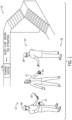
- FIG. 1 illustrates an embodiment of an amusement park ride 10 that uses a portable locker to store a rider's loose items during operation of the amusement park ride 10.
- the amusement park ride 10 includes a distribution point 12 along a queue for the amusement park ride 10 for providing a rider 14 with a portable locker 16 that secures loose items 20 belonging to the rider 14.
- the distribution point 12 may be located at an entrance 18, at a loading station, or any other location between the entrance 18 and the loading station of the amusement park ride 10.
- the amusement park ride 10 includes a control point 24 for monitoring storage of the loose items 20 within the portable locker 16.
- one or more crew members 28 may be stationed at the distribution point 12 to monitor for the loose items 20 and/or to provide the rider 14 with the portable locker 16 for storage of the loose items 20.
- the distribution point 12 may be positioned prior to the control point 24 (e.g., a metal detector) of the amusement park ride 10. However, in other embodiments, the distribution point 12 and the control point 24 may be positioned within the same location or may be overlapping. As used herein, the control point 24 is intended to denote the location where verification that loose items are properly stored and secured within the portable locker 16 takes place.
- the one or more crew members 28 may distribute the portable locker 16 to the rider 14 immediately prior to riding/participating in the entertainment experience.
- the distribution point 12 may be immediately prior or essentially overlapping with the loading station for the amusement park ride 10.
- the "loading station" as used herein is intended to denote an area where the rider 14 boards a ride vehicle of the amusement park ride.
- the one or more crew members 28 may distribute the portable locker 16 about 20 or 30 feet (about 6-9 meters) before the control point 24 or lock point.
- the portable locker 16 may be distributed to the rider 14 at any other location within the amusement park (e.g., at the entrance 18 or at an entrance to the amusement park).
- the "lock point” as used herein is intended to denote the point at which the portable locker is locked and unable to be opened to access the stored loose items.
- a “lock point” may refer to a location (e.g., all items are locked beyond a certain physical location), a time point (e.g., all items are locked after a particular time), or an event point (e.g., all items are locked before a particular event, such as a vehicle movement start).
- the riders 14 may purchase portable lockers 16 that are themed and, therefore, are already in possession of the rider 14 for use in accordance with present embodiments.
- the rider 14 may be provided with the portable locker 16 at the distribution point 12 prior to passing through the control point 24.
- the distribution point 12 may include a scanner 30 (e.g., a metal detector or other suitable scanner) that detects the presence of the loose items 20.
- the scanner 30 is a hand held scanner that may be used by the one or more crew members 28 to scan for and detect the loose items 20 on the rider 14.
- the scanner 30 may be a stationary or fixed scanner that the rider 14 may walk through. The scanner 30 alerts the one or more crew members 28 that the rider 14 has loose items 20 on their person.
- the one or more crew members 28 provides the rider 14 with the portable locker 16 and instructs the rider 14 to place their loose items 20 into the portable locker 16.
- the rider 14 may undergo additional scanning with the scanner 30 to detect other loose items 20.
- the portable locker 16 may be locked by activating a locking mechanism. As discussed in detail below, the locking mechanism may not be unlocked without receiving a lock deactivation signal transmitted after completion of the amusement park ride 10 and when the rider 14 has possession of the portable locker 16 storing their loose items 20.
- the rider 14 may proceed to the control point 24, where the one or more crew members 28 may verify that the loose items 20 are locked and secured within the portable locker 16.
- the rider 14 may proceed to place their portable locker 16 within a storage system 34 that retains the portable locker 16 while the rider 14 enjoys the amusement park ride 10.
- the storage system 34 may be positioned at any point along the queue of the amusement park ride 10. In particular, it may be desirable to position the storage system 34 at or near a loading/ section of the amusement park ride 10 to facilitate access to the storage system 34 for storage and retrieval of the portable locker 16.
- the rider 14 may exit the amusement park ride 10 and collect the portable locker 16 from the storage system 34.
- the locking mechanism of the portable locker 16 may be deactivated, thereby unlocking the portable locker 16 and allowing the rider 14 to retrieve the loose items 20 stored in the portable locker 16.
- the locking mechanism may be unlocked after receiving a signal when the ride 10 is complete and the rider 14 has possession of the portable locker 16 storing their loose items 20.
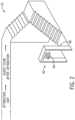
- FIG. 2 illustrates an embodiment of the amusement park ride 10 having an RFID gate 40 that is communicatively coupled to the portable locker 16 and that transmits a signal that unlocks the portable locker 16.
- the RFID gate 40 is located at an exit 42 of the amusement park ride 10. However, the RFID gate 40 may be located at any other location between the unloading section and the exit 42.
- the RFID gate 40 transmits a deactivation signal 44 that unlocks the locking mechanism on the portable locker 16, thereby allowing the rider 14 to access the loose items 20 stored in the portable locker 16.
- the amusement park ride 10 may not include the RFID gate 40. Rather, the one or more crew members 28 may deactivate the locking mechanism of the portable locker 16 using a key card or other electronic key.
- the rider 14 By only deactivating the locking mechanism of the portable locker 16 after the rider 14 enjoys the amusement park ride 10, the rider 14 is prevented from accessing the loose items 20 that may otherwise be inadvertently separated from the rider 14 during operation of the amusement park ride 10. Further, by implementing loose items storage as a portable locker 16, loading and unloading is more efficient. The rider 14 simply holds the portable locker 16, which may be opened and accessed at their leisure, or while walking towards the exit, rather than having to stop at a fixed location within the amusement park ride 10.
- FIG. 3 is a process flow diagram 46 of an embodiment of the amusement park ride 10 that uses the portable locker 16 to store the rider's loose items 20.
- the rider 14 may be provided with the portable locker 16 at the distribution point 12 and instructed to store their loose items 20 within the portable locker 16.
- the rider 14 is scanned using the scanner 30 for additional loose items 20 before the portable locker 16 is locked via, for example, a lock actuator 45.
- the rider 14 proceeds to store the locked portable locker 16 in the storage system 34, as illustrated by arrow 47.
- the rider proceeds to a loading station 49 of the amusement park ride 10.
- the rider 14 may retrieve the locked portable locker 16 from the storage system 34, as shown by arrow 51, and proceed to a second lock actuator 53 (e.g., the RFID gate 40) to unlock the portable locker 16 prior to exiting the amusement park ride 10 at the exit 42.
- a second lock actuator 53 e.g., the RFID gate 40
- the rider 14 may use the portable locker 16 to store and secure the loose items 20 prior to enjoying the amusement park ride 10.
- the portable locker 16 may include features that block the rider 14 from retrieving the loose items 20 from the portable locker 16 after the portable locker 16 is locked. In this way, the loose items 20 may be contained within the portable locker 16 during operation of the amusement park ride 10.
- the portable locker 16 may be a wearable locker that the rider 14 may take onto the amusement park ride 10. As such, the rider 14 may have possession of their loose items 20 at all times.
- FIG. 4 is a schematic view of an embodiment of the portable locker 16 that may be used by the rider 14 to store and secure the loose items 20.
- the portable locker 16 is representative of various types of portable lockers in accordance with present embodiments.
- the portable locker 16 may include, or be implemented as, a lockable container, illustrated as a pouch 48 (e.g., pouch, container, box, bag, or the like) for storing the loose items 20 (e.g., cell phone, camera, keys, hat, wallet, or any other suitable loose item).
- a lockable container illustrated as a pouch 48 (e.g., pouch, container, box, bag, or the like) for storing the loose items 20 (e.g., cell phone, camera, keys, hat, wallet, or any other suitable loose item).
- the loose items 20 are items that are capable of being separated from the riders 14 and, as provided herein, may be nonetheless referred to as loose items 20 while contained and enclosed in the pouch 48.
- the pouch 48 stores the loose items 20 in a fully enclosed manner when sealed or locked such that the rider 14 cannot directly touch or access the loose items 20.
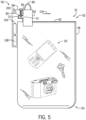
- the pouch 48 includes a sealed end 50 and a closable end 52 having a locking mechanism 56 configured to open ( FIG. 4 ) and close ( FIG. 5 ) the closable end 52.
- the locking mechanism 56 includes a lock 58 (e.g., actuatable lock), a zipper 60, and zipper teeth 62 around a perimeter 64 of the closable end 52.
- the pouch 48 may include or be implemented as a bag, a container, or any other suitable enclosure that may be used to retain and secure the loose items 20.
- the pouch 48 may be manufactured from materials such as fabrics, plastics, or both.
- at least a portion of the pouch 48 may be clear such that the rider 14 may view and/or use the loose items 20 stored in the portable locker 16.
- the pouch 48 may enable the rider 14 to, through the intervening material of the pouch 48, interact with a touch screen or buttons of electronic devices (e.g., cell phone, camera, etc.) stored within the portable locker 16.
- the rider 14 may access a camera (e.g., on a cell phone) to take a picture or video through the portable locker 16 while the portable locker 16 is locked.
- the portable locker 16 may be capable of transitioning between modes to prevent or allow access of the loose items 20 (e.g., camera, cell phone, or the like) secured within the pouch 48.
- the loose items 20 e.g., camera, cell phone, or the like
- a transmission to electronics of the pouch 48 may cause the pouch 48 to turn an area from clear to opaque (e.g., with liquid crystals).
- the rider 14 is unable to access the loose items 20, specifically electronic devices that may be used to take pictures or video.
- the portable locker 16 includes the locking mechanism 56 for securing and locking the loose items 20 within the pouch 48 to prevent removal of the loose items 20 from the portable locker 16 when the rider 14 is enjoying the amusement park ride 10.
- the locking mechanism 56 may be used to close the closable end 52 after the rider 14 places the loose items 20 into the pouch 48, as shown in FIG. 5 .
- the locking mechanism 56 may be configured such that it cannot be opened by the rider 14 until the portable locker 16 is taken to a specific location (e.g., the RFID gate 40) away from the amusement park ride 10 or a ride vehicle of the amusement park ride 10 reaches the unloading section. As shown in the embodiment of FIGS.
- the zipper 60 includes at least one protrusion 70 that engages with a complementary recess 72 of the lock 58 to close the closable end 52 and secure the loose items 20 within the pouch 48.
- the rider 14 may apply a pulling force to the zipper 60, thereby moving the zipper 60 in a direction 78 toward the lock 58.
- the zipper 60 may include one or more features to facilitate moving the zipper 60 in the direction 78.
- the zipper 60 includes a zipper pull 80 that the rider 14 or other person (e.g., the one or more crew members 28) may grip and apply the pulling force to move the zipper 60 in the direction 78. Pulling the zipper 60 in the direction 78 enables joining of the zipper teeth 62, thereby sealing (i.e., closing) the closable end 52, as shown in FIG. 5 .
- an end face 92 of the one or more protrusions 70 may push the locking pin 84 in a direction 94 to allow the at least one protrusion 70 to continue moving in the direction 78 until the notch 82 is aligned with the locking pin 84.
- the at least one or more protrusions 70 may be tapered to facilitate pushing the locking pin 84 in the direction 94. Movement of the locking pin 84 in the direction 94 compresses a spring 95 of the locking pin 84.
- the rider 14 or other person may pull the zipper 60 in a direction 104 that is substantially opposite the direction 78, thereby separating the zipper 60 from the lock 58 and decoupling the zipper teeth 62. Accordingly, the closable end 52 is opened and the rider 14 may retrieve their loose items 20 from the pouch 48.
- the locking mechanism 56 may be powered by one or more batteries 108.
- the lock 58 may include a cavity 106 sized to fit the one or more batteries 108.
- the one or more batteries 108 may include lead-acid batteries, lithium ion batteries, nickel-cadmium, nickel-zinc, or any other suitable battery that may be used to power the locking mechanism 56.
- FIG. 7 provides another example of the portable locker 16 that may be used by a rider 14 to stow the loose items 20 during operation of the amusement park ride 10.
- the portable locker 16 includes a locking loop 120, a loop lock 122, and a pouch lock 124 coupled to the pouch 48.
- the locking loop 120 extends from a first side 126 to a second side 128 of the portable locker 16.
- the locking loop 120 may be used to secure the portable locker 16 to the storage system 34 after the rider 14 secures the loose items 20 within the portable locker 16.
- the locking loop 120 is an example of one of the various locking features in accordance with present embodiments. Accordingly, while specific embodiments illustrate and describe a locking loop, the locking loop 120 may be replaced with other locking features in accordance with present embodiments.
- the portable locker 16 may be replaced by a different container (e.g., a box) that employs a corresponding locking feature (e.g., a box lock).
- the pouch 48 may be sized to accommodate specific devices (e.g., specific smart phone types) or a variety of items (e.g., keys and wallet). Different types of portable lockers 16 may be available, such as different sizes, colors, shapes, and materials.
- the portable locker 16 may be given to the rider 14 at any point prior to ride vehicle motion or start of the amusement park ride 10.
- the portable locker 16 may be distributed in the queue or, in certain embodiments, once riders 14 are loaded into the vehicles.
- the rider 14 may lock the portable locker 16 by activating the pouch lock 124 and secure the loose items 20 within the portable locker 16.
- the portable locker 16 may be part of a kit that includes a locking/unlocking device 130 that activates and deactivates the pouch lock 124.
- the locking/unlocking device 130 may be in control of the rider 14 such that access to the portable locker 16 is restricted only to the rider 14 or a person designated by the rider 14.
- the locking/unlocking device 130 may include a radio frequency (RF) chip 132 that is communicatively coupled to a corresponding RFID tag 134 associated with the pouch lock 124.
- the RF chip 132 may send one or more signals to the RFID tag 134 to enable locking and unlocking the pouch lock 124.
- the locking loop 120 allows the rider 14 to secure the portable locker 16 to the storage system 34 (e.g., racks, storage compartments) via the locking loop 120.
- a cord 140 corresponding to the locking loop 120 couples to the loop lock 122 to secure the portable locking pouch 16 to the storage system 34.
- the storage system 34 may include a pouch attachment feature that facilities securing the portable locker 16 to the storage system 34. While illustrated as separate locking mechanisms (e.g., the loop lock 122 and pouch lock 124) in FIG. 7 , in some embodiments, a single locking mechanism is shared for both the pouch access point (e.g., the pouch lock 124) and the locking loop 120.
- the cord 140 of the locking loop 120 may pass through a receptacle and then engage with the pouch lock 124, which can then be locked to not only secure the locking loop 120 in place, but also to lock the pouch 48 closed.
- the portable locker 16 may include a finger pad that is used to lock and unlock the loop lock 122, the pouch lock 124, or both.
- the finger pad registers a fingerprint of the rider 14 assigned to the portable locker 16. In this way, no one other than the rider 14 assigned to the portable locker 16 may retrieve the stored loose items 20 in the pouch 48 and/or the portable locker 16 from the storage system 34.
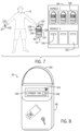
- FIG. 8 illustrates an embodiment of the portable locker 16 having a finger pad 146 on the pouch 48 that may be used to lock and unlock the portable locker 16.
- the rider 14 may activate and deactivate the pouch lock 124 by pressing their finger against the finger pad 146.
- the finger pad 146 may include a memory 148 that stores the fingerprint of the rider 14.
- the pouch lock 124 is activated to lock the pouch lock 124 and secure the loose items 20 in the portable locker 16 or deactivated to unlock the pouch lock 124 and allow the rider 14 to retrieve the items from theportable locker 16.
- the rider 14 may store the portable locker 16 in the storage system 34 corresponding to the amusement park ride 10.
- the storage system 34 may include a rack having a locking mechanism that secures the portable locker 16 to the storage system 34. The locking mechanism may be controlled by the rider 14 such that the portable locker 16 assigned to the rider 14 may not be removed from the storage system 34 by another rider or park guest.
- the storage system 34 may include a storage rack 150 having a plurality of compartments 152 that may be used to store and secure the portable locker 16 while the rider 14 enjoys the amusement park ride 10.
- the plurality of compartments 152 may include cubbies, hooks, shelves, or the like.
- the plurality of compartments 152 may be arranged in a series of rows and columns, where each row and/or column may be assigned to a ride vehicle of the amusement park ride 10.
- the portable locker 16 may be assigned to a specific compartment of the plurality of compartments 152.
- the plurality of compartments 152 may each be labeled (e.g., serialized) such that each portable locker 16 and locking/unlocking device 130 are assigned to a respective compartment of the plurality of compartments 152.
- Each compartment of the plurality of compartments 152 may include a storage lock 156 that may be activated and deactivated by the locking/unlocking device 130 in a manner similar to the pouch lock 124 to release the portable locker 16 from the compartment. In this way, the portable locker 16 may not be removed from the respective compartment 152 by another rider or park guest.
- the rider 14 may activate the pouch and storage lock 124, 156, respectively, to secure the portable locker 16 to the storage rack 150.
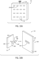
- Other storage racks may include different engagement features (see FIGS. 9 and 10A ).
- the rider 14 may proceed to unlock the pouch and storage lock 124, 156, respectively, to retrieve the loose items 20 from the portable locker 16. Once the rider retrieves their items from the portable locker 16, the rider 14 may place the portable locker 16 in a collection bin that may collect the portable lockers 16 and allow reuse by other riders of the amusement park ride 10.
- the storage system 34 may be stationary or mobile. That is, the storage system 34 may permanently fixed to a location or may move from one location to another location (e.g., from a loading station to an unloading station) within the amusement park ride 10. For example, the storage system 34 may be located at a central location near the loading and unloading stations of the amusement park ride 10. The rider 14 may approach the storage system 34 prior to boarding the ride vehicle to store and secure the portablelocker 16. Similarly, the rider 14 may approach the storage station 34 after unloading from the ride vehicle to retrieve the stored items.
- the plurality of compartments 152 associated with the storage station 34 may include a storage side facing the loading station and a pick-up side facing the unloading station.
- each compartment of the plurality of compartments 152 may include a first door on the storage side and a second door on the pick-up side, each door having a lock.
- the rider 14 may access the storage side prior to boarding the ride vehicle (e.g., from a load queue upstream of the loading point) via the first door and may access the pick-up side from the unloading station (e.g., from an exit queue) via the second door to mitigate congestion at the storage system 34.
- This double-sided locker may be mechanically actuated such that doors open for guests to place items in the loading side during ride loading and then closes during operation of the ride 10. Similarly, when riders are exiting, the doors may be actuated to open from the unloading side during unloading.
- the plurality of compartments 152 includes a pouch attachment feature (e.g., pegs, hooks, or the like) that may be used to hang and secure the portable locker 16 onto the storage system 34.
- a pouch attachment feature e.g., pegs, hooks, or the like
- the rider 14 may attach the locking loop 120 (or some other locking mechanism) to the pouch attachment feature associated with the respective compartment of the plurality of compartments 152.
- FIG. 9 is an exemplary embodiment of the storage system 34 in which the storage rack 150 is a peg board 157, or other similar board, that may facilitate mounting and securing the portable locker 16 to the storage system 34.
- the peg board 157 may include a plurality of pegs 158 (e.g., protrusions) or any other suitable support (e.g., hook, latch, or the like) that may engage with the locking loop 120 of the pouch to retain and secure the portable locker 16 to the storage rack 150.
- pegs 158 e.g., protrusions
- any other suitable support e.g., hook, latch, or the like
- Each peg 158 extending from a surface 159 of the storage rack 150 may be assigned a number or other identifier that corresponds to a particular portable locker 16.
- the rider 14 may secure the portable locker 16 to the respective peg 158 as discussed previously with reference to FIG. 7 .
- the plurality of compartments 152 or some other storage system 34 may rotate such that there is only a single door or access point for a particular rider.
- the storage rack 150 may include the peg board 157 (or other storage features) on both sides and rotate about a motor driven spindle such that the same items placed on the storage rack 150 at an entry point of the ride 10 are accessible at an exit point of the ride 10.
- the storage system 34 includes a spindle 162 configured to rotate about an axis 164 to facilitate storage and retrieval of the portable locker 16 by the rider 14.
- the storage system 34 may be positioned between the loading and unloading stations of the amusement park ride 10 in a manner that a first side 166 of the storage rack 150 faces the loading station and a second side 168 of the storage rack 150 faces the unloading station.
- a first group of riders located at the loading station may lock and secure their respective portable locker 16 to the retaining member 158 on the first side 164
- a second group of riders at the unloading station may unlock and retrieve their respective portable locker 16 from the second side 168.
- the spindle 162 of the storage rack 150 may be rotated about the axis 164, as shown by arrow 170, to allowa group of riders at the loading station to lock and secure their respective portable locker 16 to the retaining members 158 located on the second side 168 of the storage rack 150, and allow the first group of riders to unlock and retrieve their respective portable locker 16 after enjoying the amusement park ride 10.
- the rotation of the spindle 162 may be achieved manually or mechanically.
- the spindle 162 is coupled to a motor 172 that rotates the spindle 162 about the axis 164.
- the one or more crew members 128 may manually rotate the storage rack 150.
- each individual or a subset of storage areas e.g., lockers or peg section
- the rotational locking feature 180 includes a first bar 182 radially extending away from a surface 184 of the pouch 48 of the portable locker 16, and a second bar 186 positioned orthogonal to the first bar 182.
- the second bar 186 is configured to rotate about an axis 190 of the first bar 182 to move the rotational locking feature 180 between an unlocked configuration and a locked configuration ( FIG. 10C ).
- the receptacles 178 on a front face 192 of the wall 176 may be arranged to receive the rotational locking feature 180 in an aligned configuration (e.g., the bars 182, 186 of the rotational locking feature 180 are aligned in parallel when unlocked).
- FIG. 10C illustrates a back face 194 of the storage system 34 where the second bar 186 has been rotated about the axis 190, as shown by arrow 196.
- the second bar 186 is orthogonal to a widest dimension 200 of the receptacle 178. In this way, the portable locker 16 may be retained on the storage system 34.
- different shapes e.g., stars, triangles, squares, or character profiles
- the storage system 34 may include a locker that secures a plurality of portable lockers 16.
- the rider actuates the locking mechanism (e.g., the locking mechanism 52, pouch lock 124) for their respective portable locker 16
- the rider 14 may place the locked portable locker 16 into the locker of the storage system 34.
- Each locker of the storage system 34 may be associated with a ride vehicle of the amusement park ride 10. Therefore, once the locked portable lockers 16 for each rider 14 assigned to the same ride vehicle are placed in the locker, the one or more crew members 28, or an operator of the amusement park ride, may lock the locker to secure the riders' portable lockers 16 during operation of the amusement park ride 10.
- the locker may be automatically locked.
- a control system may transmit a signal to the locker that actuates the lock once all the riders 14 are secured in the ride vehicle associated with the locker. In some embodiments, this may include detecting the presence of the portable lockers 16 in the larger locker of the storage system 34 (e.g., via a weight measurement or wireless communications). The control system may also unlock the locker after the amusement park ride 10 experience is complete. For example, when the ride vehicle enters the unloading station, passes through an unlock gate, or the like.
- the lockers may be located in a floor area or overhead area on an approach to the ride vehicle or in the ride vehicle itself (e.g., ride vehicle 226, see FIG. 11 ).
- the lockers may pop up from the floor or down from the ceiling and allow riders 14 to place their belongings into the lockers. After the riders 14 are properly seated and restrained, the lockers may recede into the floor or ceiling and then open again when the ride returns and riders 14 are exiting, which allows the riders to reclaim their belongings.
- the storage system may be mobile. That is, the storage system may include features that move the portable locker 16 from one location to another location within the amusement park ride 10. For example, after the portable locker 16 is locked and secured to the storage system, the storage system may transport the portable locker 16 from the loading station to the unloading station.
- a mobile storage system may allow the riders to secure their assigned portable locker 16 to the storage system 34 at the loading station of the amusement park ride 10, which may be at a location different from the unloading station.
- FIG. 11 illustrates an embodiment of the amusement park ride 10 having a mobile storage system 210 that transports the portable locker 16 from a loading station 212 to an unloading station 214.
- the mobile storage system 210 includes a transport system 218 that extends from the loading station 212 to the unloading station 214 of the amusement park ride 10.
- the transport system 218 may receive a storage rack 220 retaining one or more portable lockers 16 or may receive individual portable lockers 16.
- the transport system 218 moves the rack 220 and/or the individual portable lockers 16 from the loading station 212 to the unloading station 214 while the rider 14 enjoys the amusement park ride 10.
- the rider 14 may activate the locking mechanism (e.g., the locking mechanism 56 or pouch lock 124) to lock the loose items 20 within the portable locker 16, as discussed previously.
- the rider 14 or the one or more crew members 28 may secure the locked portable locker 16 to the rack 220 at the loading station 212.
- the rider 14 may proceed to board the ride vehicle 226 and enjoy the amusement park ride 10.
- the transport system 218 may transport the portable lockers 16 by moving the rack 220 in a direction 230 towards the unloading station 214.
- the transport system 218 may include a conveyor belt, a railing system, or any other suitable transport system that moves the portable locker 16 from the loading station 212 to the unloading station 214.
- the transport system 218 may include retaining features such as hooks, fasteners, connectors, or the like that support and secure the storage rack 220 and/or the portable locker 16 onto the transport system 218.
- a portion of the transport system 218 may be positioned below the ride vehicle 226. This may be useful in embodiments where the loading station 212 of the amusement park ride 10 is located on one side of the ride vehicle 226, and the unloading station 214 is positioned on an opposite side of the ride vehicle 226. That is, a pouch storage section of the transport system 218 (e.g., section where the rider 14 secures the portable locker 16 to the storage system 34) may be located on a loading side of the ride vehicle 226 that is substantially opposite an unloading side of the ride vehicle 226, and a pouch pick-up section (e.g., section where the rider 14 retrieves the portable locker 16 after unloading from the ride vehicle 226).
- a pouch storage section of the transport system 218 e.g., section where the rider 14 secures the portable locker 16 to the storage system 34
- a pouch pick-up section e.g., section where the rider 14 retrieves the portable locker 16 after unloading from the ride vehicle 226).
- the transport system 218 may extend from the loading station 212 to the unloading station 214 below ride tracks 232 of the amusement park ride 10 such that the transport system 218 does not interfere with operation of the amusement park ride 10, as shown in FIG. 11 . Accordingly, the portable lockers 16 follow a path that is underneath the ride tracks 232 when transported from the loading station 212 to the unloading station 214. In this way, the transport system 218 does not interfere with a trajectory of the ride vehicle 226 during operation of the amusement park ride 10.
- the transport system 218 may be positioned above the tracks 232 and the ride vehicle 226.
- the transport system 218 may be positioned at any other location that transports the portable lockers 16 from the loading station 212 to the unloading station 214 and does not interfere with movement of the ride vehicle 226 along the tracks 232 during operation of the amusement park ride 10. Therefore, once the rider 14 unloads the ride vehicle 226, the rider 14 may retrieve the portable locker 16 assigned to them at the unloading station 214, and collect their loose items 20 from the portable locker 16 at or near the unloading station 214 before exiting the ride 10.
- a ride manager/crew member may take the rack 220 and/or the portable locker 16 from the transport system 218 and position it in a designated location for pickup at the exit of the ride 10.
- the rack 220 and/or the portable locker 16 may be moved from the transport system 218 to the designated location for pickup by a mechanical system (e.g., a robotic arm or the like).
- the loading station 212 and the unloading station 214 of the amusement park ride 10 may be located on the same side of the ride vehicle 226. In this particular configuration, the riders enter and exit the ride vehicle 226 from the same side, as opposed to different sides as illustrated in FIG. 11 .
- FIG. 12 illustrates an embodiment of the amusement park ride 10 having the loading station 212 and the unloading station 214 positioned on the same side of the ride vehicle 226 and the ride tracks 232.
- the transport system 218 transports the portable lockers 16 along a path that is parallel to at least a portion of the tracks 232.
- the transport system 220 includes a conveyor belt 236 that transports the portable lockers 16 in a direction 238 from a pouch drop-off site 240 at the loading station 212 to a pouch pick-up site 246 at the unloading station 214.
- the rider 14 may place their locked portable locker 16 on a surface of the conveyor belt 236 prior to boarding the ride vehicle 226 at the loading station 214.
- the conveyor belt 236 may move at a pace that delivers the locked portable locker 16 to the pouch pick-up site 246 at approximately the same time that the ride vehicle 226 used by the respective rider 14 arrives at the unloading station 214.
- the conveyor belt 236 may feed the locked portable lockers 16 to a container located at the pouch pick-up site 246.
- each ride vehicle 226 may be assigned a container. Accordingly, the rider 14 may approach the container assigned to the ride vehicle 226 they exited from to retrieve their respective portable locker 16. Following retrieval of the portable locker 16, the rider 14 may unlock the locking mechanism 56 or pouch lock 124 electromagnetically (e.g., via the RFID gate 40, locking/unlocking device 130, or the like) or mechanically (e.g., a key or similar device), as discussed previously.
- the locking mechanism 56 or pouch lock 124 electromagnetically (e.g., via the RFID gate 40, locking/unlocking device 130, or the like) or mechanically (e.g., a key or similar device), as discussed previously.
- the portable lockers 16 may be implemented as or in conjunction with autonomous vehicles on wheels that follow a path from the loading station 212 to the unloading station 214 or other location where the rider 14 may retrieve the stored loose items 20.
- the autonomous vehicles may include features (e.g., sensors) that block the autonomous vehicles from colliding with park guests and/or objects (e.g., walls, park structures, and the like).
- the portable locker 16 may not be autonomous. Rather, the portable locker 16 may include wheels that follow a predetermined path (e.g., a track or a programmed path specifically based on space) from the loading station 212 to a loose item pickup location associated with the amusement park ride 10.
- the portable lockers 16 may each have an actuator to raise the portable locker 16 up to the height of a ride vehicle seat or position the portable locker 16 in front of the ride vehicle seat, etc. to allow the riders to place the loose items 20 within the portable locker 16 after the rider has boarded the ride vehicle 226.
- the portable locker 16 may be used to store and secure the loose items 20 to keep the loose items 20 from being separated from the rider 14 during operation of the amusement park ride 10. It is now recognized that park guests (e.g., the rider 14) may not want to be separated from their loose items while on the amusement park ride 10. Additionally, it may be desirable for the rider 14 to capture the ride experience by taking a video or picture of themselves while enjoying the amusement park ride 10. Accordingly, the portable locker 16 may be configured to allow the rider 14 to secure the portable locker 16 to themselves or to the ride vehicle 226 such that the loose items 20 are in the possession of the rider 14.
- a rider of the amusement park ride may want to have their stored items with them at all times. That is, certain riders may not be comfortable storing their items in a remote area that is separate from the ride vehicle 226. Accordingly, it may be desirable for the rider 14 to secure the portable locker 16 to the ride vehicle 226 (e.g., a ride seat) of the amusement park ride 10.
- the rider 14 may continue to have access to the loose items 20 stored in the portable locker 16 and the items 20 may be in the line of sight of the rider 14.
- wait times and congestion of riders at the pouch storage/drop-off and pick-up stations 240, 246, respectively, may be mitigated.
- FIG. 13 is an embodiment of the ride vehicle 226 having an integrated storage system 250 that may be used to secure the portable locker 16 to the ride vehicle 226.
- the integrated storage system 250 may be coupled to a ride seat 254 (e.g., a back support of the ride seat).
- the integrated storage system 250 may include a retaining bar 258 having one or more retaining features that engage with a complementary feature on the portable locker 16 to secure the portable locker 16 to the ride vehicle 226 in a manner similar to the storage rack 150 discussed previously.
- the retaining bar 258 may include hooks, clips, pegs, bins, pockets, connectors, or the like that receive and retain the portable locker 16 within the ride vehicle 226 during operation of the amusement park ride 10.
- the retaining bar 258 is positioned on a back portion 260 of the rider seat 254 such that the portable locker 16 is in front of a rider 14 occupying a ride seat that is behind the ride seat 254 having the retaining bar 258.
- the retaining bar 258 may be positioned on any portion of the ride vehicle 226 (e.g., a side wall, under the ride seat, seat or row divider, etc.).
- the portable locker 16 may be clear such that the rider 14 may access a touch screen or buttons of electronic devices stored within the portable locker 16.
- the rider 14 may access a camera (e.g., on a cell phone) to take a picture or video through the portable locker 16 while the portable locker 16 is secured to the ride vehicle 226.
- the attachment point to the ride vehicle 226 e.g., the integrated storage system 250
- the portable locker 16 and the integrated storage system 250 may include indicators to facilitate proper alignment for capturing video data (e.g., photos or video) during the ride 10.
- a storage lock of the integrated storage system 250 may be activated by a control system of the amusement park ride 10.
- FIG. 14 illustrates an embodiment of the amusement park ride 10 in which the ride seat 254 of the ride vehicle 226 includes one or more sensors 270 that are communicatively coupled to the retaining bar 258 and a control system 272 of the amusement park ride 10.
- the one or more sensors 270 may transmit a signal 274 to the retaining bar 258 and/or the control system 272 indicating that the ride seat 254 is occupied and that a portable locker 16 may need to be secured to the integrated storage system 250.
- near-field communications may be utilized to determine that a rider 14 has a portable locker 16 or smartphone and is in the seating area.
- the rider 14 may be prompted to mount the portable locker 16 to the integrated storage system 250.
- the retaining bar 258 transmits another signal 276 to the control system 272 indicating that the portable locker 16 is attached.
- the control system 272 activates a locking mechanism of the integrated storage system 250 to retain and secure the portable locker 16 to the retaining bar 258 of the ride vehicle 226.
- the control system 272 releases the ride vehicle 226 from the loading station 214.
- the control system 272 may allow the operator of the ride 10 to bypass attaching a portable locker 16 to the retaining bar 258, for example, in situations where the rider 14 does not have any loose items 20 that need to be stored in the portable locker 16.
- the retaining bar 258 of the integrated storage system 250 may include a pair of brackets 280 sized and shaped to receive a complementary feature disposed on the portable locker 16.
- the complementary feature may engage the brackets 280 to retain the portable locker 16 to the ride vehicle 226.
- the complementary feature may include an I-beam 284 or other similar feature disposed on at least a portion of an exterior surface 286 and extending along a longitudinal axis 288 of the portable locker 16.
- the I-beam 286 may slide into a channel 290 defined by the pair of brackets 280 to retain the portable locker 16 to the ride vehicle 226.
- the one or more sensors 270 may receive a signal 292 from a transmitter 294 located on the portable locker 16 via a wireless communication link.
- the signal 292 transmitted by the transmitter 294 on the portable locker 16 may indicate that the portable locker 16 is within the ride vehicle 226.
- the one or more sensors 270 may output the locking signal 274 to a locking mechanism 298 (e.g., a mechanical lock such as a latch) that activates the locking mechanism 298 and secures the portable locker 16 to the integrated storage system 250.
- a locking mechanism 298 e.g., a mechanical lock such as a latch
- the retaining bar 258 and/or its associated locking components may be switched from an unsecured configuration to a secured configuration based on receiving the securing signal 274 or an unsecuring signal.
- the integrated storage system 250 may transmit the signal 276 to the control system 272 of the amusement park ride 10 indicating that the portable locker 16 is secured in the ride vehicle 226.
- the control system 272 may activate a light 300 on the ride vehicle 226 to indicate that the portable locker 16 is secured and the ride vehicle 226 is released from the loading station 212.
- the one or more sensors 270 detect that the portable locker 16 is within the ride vehicle 226 but does not detect that the portable locker 16 is retained within the integrated storage system 250, the one or more sensors 270 do not output the signal 274 to the control system 272 and the ride vehicle 226 is not released from the loading station 212.
- the light 300 may not be activated or may display a color indicating that the ride vehicle 226 may not be released.
- the light 300 may be red to alert the operator of the amusement park ride 10 that the portable locker 16 is not secured within the ride vehicle 226 (e.g., the that ride vehicle 226 has one or more unsecured portable lockers 16 on board).
- the ride vehicle 226 may also send a signal to the central controller either permitting movement when all detected portable lockers 16 are secured or preventing movement based on detection of one or more unsecured portable lockers 16.
- the integrated storage system 250 may be under a seat pan 302 of the ride seat 254.
- the seat pan 302 may include a storage space between a seat base and a seat pan cover.
- the storage space may be accessible (e.g., open) when the seat cover is in a first position, and is closed (e.g., locked) when the seat pan cover is in a second position.
- the seat pan cover may be positioned parallel to a back rest 304 of the ride seat 254 when the ride seat 254 is not occupied.
- the storage space may be readily accessible for the rider 14 to stow the items.
- the rider 14 may lower the seat pan cover to the second position.
- the seat pan cover may be orthogonal to the back rest 304 such that the seat pan cover covers the storage space and allows the rider 14 to occupy (e.g., sit) the ride seat 254. Therefore, the items 20 may be secured within the storage space of the seat pan 302during operation of the amusement park ride 10.
- the rider 14 may retrieve the stowed items 20 when the rider 14 stands up after completion of the amusement park ride 10 experience. In this way, the rider 14 may be in possession of their items during operation of the amusement park ride 10.
- the rider 14 may be unable to remove the stowed items 20 from the storage space within the ride seat 254 during operation of the amusement park ride 10.
- the seat pan 302 may include a locking mechanism (e.g., a mechanical lock, latch, hook, or the like) to secure the seat pan cover to the base after the rider 14 stows the items 20 in the storage space.
- the portable locker 16 may be released from the integrated storage system 250 upon conclusion of the ride 10, e.g., the controller may send a release signal to the integrated storage system 250 upon entry of the vehicle 226 into an unloading area.
- the release signal may trigger a switch of the retaining bar 258 to the unsecured configuration and, in certain embodiments, a visible indicator that the rider 14 may remove the portable locker 16. Further, control of the release of the portable locker 16 from the integrated storage system 250 may be in parallel or in series with permitting riders 14 to unlock the pouch 48. In certain embodiments, the riders 14 may be encouraged to depart more quickly by separating signals triggering the release of the portable locker 16 from the integrated storage system 250 from unlocking of the pouch 48. That is, the unlocking (e.g., via a transmitted unlocking signal) may only be possible at a location separated from the ride vehicle 226 to prevent dawdling during the unloading process. Accordingly, the riders 14 may take their portable lockers 16 from the ride vehicle 226 to the unlocking location.
- the portable locker 16 may be wearable (e.g., a wearable locker) such that the rider 14 may have possession of their loose items 20 at all times during the ride.
- the portable locker 16 may include features that allow the rider 14 or the one or more crew members 28 (e.g., an amusement park employee tasked with managing a queue or access point) to secure the portable locker 16 to the rider 14.
- FIG. 15 illustrates an embodiment of a wearable pouch310 that may be worn by the rider 14 of the amusement park ride 10 before, during, and after operation of the amusement park ride 10. That is, the rider 14 may have possession of the items stored in the wearable pouch 310 at all times during the ride experience.
- the wearable pouch 310 may come in various sizes and shapes to accommodate various items and rider preferences.
- the wearable pouch 310 may include features that block unlocking the wearable pouch 310.
- the wearable pouch 310 may include features that may block or allow the use of cell phones or other electronic devices by the rider 14 after the items 20 are stored in the wearable pouch 310.
- the wearable pouch 310 may be made from an opaque material that blocks the rider 14 from viewing and/or accessing the touch screen on the electronic devices stored within the wearable pouch 310.
- the pouch material may have a thickness that is unsuitable for accessing buttons or a touch screen of the electronic device stored within the wearable pouch 310.
- the wearable pouch 310 may act as a Faraday cage such that the electronic devices stored within the wearable pouch 310 are unable to transmit signals.
- the wearable pouch 310 may be manufactured from a clear material.
- the wearable pouch 310 may be capable of transitioning between modes to prevent or allow photos or operation of the device within. For example, in areas where pictures are not allowed, a transmission to electronics of the bag may change in transparency, e.g., cause it to turn an area from clear to opaque (for example, with liquid crystals).
- the wearable pouch 310 includes a restraint 316 having a locking mechanism 320 that allows the rider 14 to secure the wearable pouch 310 to their person.
- the wearable pouch 310 is restrained at the waist 324 of the rider 14.
- the wearable pouch 310 includes a pouch 330 that may be used to store the rider's items during operation of the amusement park ride 10 and a pouch lock 332 that secures the items within the pouch 330.
- a pouch 330 may be used to store the rider's items during operation of the amusement park ride 10 and a pouch lock 332 that secures the items within the pouch 330.
- a pouch lock 332 that secures the items within the pouch 330.
- the restraint 316 may include a strap or belt 340 having a first portion 342 of the locking mechanism 320 on a first terminal end 346 and a second portion 348 of the locking mechanism 320 on a second terminal end 350 that is spaced apart and substantially opposite the first terminating end 346.
- the first portion 342 of the locking mechanism may engage the second portion 348 of the locking mechanism 320 to couple the terminating ends 346, 350 of the belt 340, and thereby secure the wearable pouch 310 to the rider 14.
- the locking mechanism 320 includes a clip, buckle, snap-fit connectors, or any other suitable locking mechanism that may secure the wearable pouch 310 to the rider 14.
- the restraint 316 may be adjustable to accommodate various shapes and sizes of the riders.
- the locking mechanism 320 may include a transmitter 356 that transmits a lock signal 358 to the pouch lock 332 when the rider 14 passes through a control point (e.g., the control point 24) of the amusement park ride 10. Similarly, the locking mechanism 320 may transmit an unlock signal 359 to the pouch lock 332 after the ride 10 is complete and the ride vehicle 226 is at the unloading station 214. In some embodiments, the restraint lock 354 and the pouch lock 332 are the same mechanism.
- the rider 14 may walk through a first electromagnetic station positioned at the loading station 212 (e.g., at the control point 24).
- the electromagnetic station transmits a wireless signal to the pouch and restraint locks 332, 354, thereby locking the pouch and restraint locks 332, 354.
- the rider 14 may walk through a second electromagnetic station at the unloading station 214 (e.g., the RFID gate 40). Similar to the first electromagnetic station, the second electromagnetic station transmits a second signal to the pouch and restraint locks 332, 354, thereby unlocking the pouch 330 and the restraint 316, respectively, and allowing the rider 14 to retrieve the stored items.
- the rider 14 may deposit the wearable pouch 310 in a storage bin before exiting the amusement park ride 10.
- the restraint 316 may be positioned on the rider 14 in a manner that does not allow the rider 14 to access the restraint lock 354 during operation of the amusement park ride 10. In this way the rider 14 may be unable to remove the wearable pouch 310 while on the amusement park ride 10.
- the restraint 316 of the wearable pouch 310 wraps around the rider's waist 324, similar to a belt, such that the pouch 330 is positioned on a front side of the rider 14, and the restraint lock 354 is positioned on a lateral side or back side of the rider 14.
- the rider 14 may have limited or no access to the restraint lock 354 during operation of the ride 10. Therefore, the rider 14 may be unable to unlock the restraint lock 354 while enjoying the ride 10.
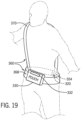
- FIGS. 18-21 illustrate various other embodiments of the restraint 316 associated with the wearable pouch 310.
- FIG. 18 illustrates an embodiment of the wearable pouch 310 having a backpack-like configuration.
- the restraint 316 of the wearable pouch 310 includes a set of straps 360 that are each coupled to the pouch 330 and to one another via the locking mechanism 320.
- the straps 360 may be adjustable to accommodate riders of different shapes and sizes.
- the rider 14 may slide each arm through a respective loop 364 defined by each strap in the set of straps 360 such that the pouch 330 is positioned on the front side of the rider 14.
- FIG. 19 also illustrates an embodiment of the wearable pouch 310 having the set of straps 360 arranged in a sash-like configuration (e.g., having one strap of the set of straps 360 extending from across the rider 14 at a diagonal from the right side of the rider's waist to the left side of the rider's shoulder, or vice versa).
- a first strap 368 of the set of straps 360 may be positioned around the waist 324 of the rider 14 (e.g., similar to a belt), and a second strap 370 of the set of straps 360 may be positioned across a torso of the rider 14 (e.g., from the right side to the left side of the rider 14 or vice versa) such that the second strap 370 wraps over a shoulder of the rider 14 and connects to the first strap 368 on the back side of the rider 14 at a location that is opposite a side where the second strap 370 wraps around the shoulder of the rider 14.
- the locking mechanism 320 of this configuration may be positioned such that it is difficult for the rider 14 to reach.
- a ride operator or other park guest may assist with engaging and disengaging the locking mechanism 320.
- the locking mechanism 320 of each of these wearable pouch embodiments may be configured such that the locking mechanism can only be actuated by a ride operator using an electronic key or the like.
- the wearable pouch 310 may include features that may allow the rider 14 to activate features on the electronic device (e.g., cell phone, camera, etc.) stored within the wearable pouch 310.
- the wearable pouch 310 may include a trigger that may allow video and/or photo taking.
- the wearable pouch 310 may have a remote that the rider 14 uses to actuate the trigger and allow video and/or photo taking.
- the wearable pouch 310 may include a transmitter that blocks the rider 14 from taking video and/or pictures with cell phones during operation of the amusement park ride 10 or at certain locations throughout the amusement park. This may be done by disabling the trigger.
- the transmitter may send a signal to the electronic device stored in the wearable pouch 310 to alert the electronic device that the area is restricted and video and picture taking are not allowed.
- the electronic device may receive instructions to block the camera. This may be achieved via the transmitter on the wearable pouch 310 or directly from an area transmitter.
- the wearable pouch 310 itself may be capable of actuation to block access when signals are received from transmitters in certain areas by, for example, blocking a clear access window.
- the transmitter may provide an output that indicates the rider/guest is not in a restricted area and video and/or picture taking is allowed.
- Embodiments of the present disclosure also include a wearable pouch having a phone case that may be separated from the pouch 330 to allow the rider 14 to access their cell phone after the pouch 330 and/or restraint 316 is locked (e.g., prior to boarding the amusement park ride 10).
- FIGS. 20 and 21 illustrate an embodiment of the wearable pouch 310 having a phone case 374 (e.g., pouch) coupled to a retractable lanyard 380.
- the retractable lanyard 380 may be coupled to a reel 382 that forms part of the pouch 330.
- the rider 14 may pull the phone case 374 away from the pouch 330 to access and engage with their cell phone 386.
- the reel 382 rotates about an axis 392 in a direction 394 (e.g., counter clockwise) and unwinds the retractable lanyard 380 (see FIG. 21 ).
- the reel 382 may continue to rotate to release the retractable lanyard 380, thereby increasing a distance 396 between the pouch 330 and the phone case 374.
- the reel 382 may lock automatically or manually to maintain the retractable lanyard 380 at the desired distance 396 away from the phone case 374 without the rider 14 having to continuously exert the pull force 390 on the retractable lanyard 380.
- the reel 382 may be unlocked to allow the retractable lanyard 380 to retract, thereby decreasing the distance 396 between the pouch 330 and the phone case 374.
- the reel may rotate about the axis 392 in a direction that is substantially opposite the direction 394 (e.g., clockwise) to reel the retractable lanyard 380 and decrease the distance 396 between the phone case 374 and the pouch 330.
- the phone case 374 may be secured to the restraint 316 of the wearable pouch 310.
- the phone case 374 may have a clip or fastener 400 (e.g., snap-fit connectors, magnets, or any other suitable fastener) that enable the rider 14 to secure the phone case 374 to the strap 360 of the restraint 316 when the cell phone 386 is not in use and during operation of the amusement park ride 10.
- the reel 386 may have an internal lock (e.g., a pin and lock mechanism) that disables the reel 386 from unwinding.
- the reel 386 is not disabled but the device (e.g., phone) is clipped/locked in a certain position such that even if the reel 386 winds/unwinds, the device cannot substantially move.
- the reel 386 may include a sensor 406 that may activate a locking mechanism within the reel when the rider boards the amusement park ride.
- the sensor may receive a signal from the ride vehicle that activates a retracting mode of the locking mechanism.
- the locking mechanism may automatically retract (e.g., reel) the retractable lanyard to decrease the distance between the pouch and the phone case to allow the rider to secure the phone case to the restraint of the wearable pouch.
- the locking mechanism may block the retractable lanyard from being released (e.g., unreel) when the rider exerts a pull force on the phone case. In this way, the rider 14 may not have access to the cell phone 386 during operation of the amusement park ride 10.
- the sensor 406 may receive a deactivation signal from the ride vehicle 226 or an unlocking station (e.g., the RFID gate 40) within the unloading station 214 that may deactivate the locking mechanism and allow the rider 14 to unreel the retractable lanyard 380 to access and engage the cell phone 386 in the phone case 374.
- an unlocking station e.g., the RFID gate 40
- the portable locker 16 may be part of an entertainment system that includes a plurality of portable lockers 16 nested within a portable locker of the portable lockers 16.
- the locking mechanism 56 of each portable locker of the plurality of portable lockers 16 may be activated and/or deactivated at different times using a different key (e.g., mechanical or electromagnetic).
- FIG. 22 illustrates an embodiment of an entertainment system 410 having a pouch 416 that includes a plurality of sub-pouches 420 where each pouch of the plurality of sub-pouches 420 is nested within another pouch of the plurality of sub-pouches 420.
- An innermost pouch 424 may include a prize 426 (e.g., reward, trinket, or the like) that may be retrieved by a user after unlocking each pouch 416, 420, 424 from the outermost pouch 416 to the innermost pouch 424.
- a prize 426 e.g., reward, trinket, or the like
- the entertainment system 410 may be a scavenger hunt pouch kit having a set of pouches 416, 420, 424 nested within another pouch.
- the scavenger hunt pouch kit includes three pouches. However, any other suitable number of pouches may be used.
- the innermost pouch 424 is shaped and sized to be nested within a second pouch 430 that is shaped and sized to be nested within the outermost pouch 416.
- Each pouch 416, 424, 430 includes a pouch lock 434 that the user may unlock by following a set of clues that lead the user to an unlocking station, where the desired pouch 416, 424, 430 may be unlocked to expose the pouch nested within the previous pouch and provide a subsequent clue that leads the user to a second unlocking station.
- the user may continue to access clues and unlock the plurality of pouches 420 until the innermost pouch 424 is accessible and the prize 426 stored within the innermost pouch 424 (e.g., via a series of RFID locks 434) may be retrieved by the user.
- the scavenger hunt pouch kit may not include multiple pouches. Rather, the scavenger hunt pouch kit may include a single pouch with multiple pouch locks that may each be unlocked at different unlocking stations throughout the amusement park. The user may retrieve the prize within the pouch after all the pouch locks have been unlocked.
- a system in an aspect comprises a portable locker comprising a container configured to receive and store items, a first lock coupled to the container and configured to lock the container to block access to the stored items, wherein the first lock comprises a detector configured to receive a wireless signal, and wherein receiving the wireless signal causes the first lock to lock or unlock, and a restraint coupled to the container and comprising a second lock, wherein the second lock is configured to secure the portable locker to a rider of an amusement park ride.
- the system further comprises a lock control point comprising a first transmitter to transmit the wireless signal to cause the first lock of the portable locker to lock, wherein the lock control point is located before a load zone for a ride vehicle, and an unlock actuation station comprising a second transmitter configured to transmit a second wireless signal to unlock the portable locker.
- system further comprises a transmitter disposed on a key comprising a wristband, and wherein the transmitter is a radio frequency (RF) chip configured to transmit the wireless signal, and wherein the detector is a radio frequency identification (RFID) tag.
- RF radio frequency
- the restraint comprises a cord having a first end coupled to a first side of the container and a second end removably coupled to a second side of the container opposing the first side, thereby forming a loop, and wherein the second lock is coupled to the second end.
- the restraint comprises a first strap coupled to the container and terminating in a first end and a second strap coupled to the container and terminating in a second end, wherein the first end comprises a first portion of the second lock and the second end comprising a second portion of the second lock, and wherein the second portion is configured to be removably coupled to the first portion to secure the portable locker to the rider.
- the first lock is communicatively coupled to the second lock, and wherein the second lock comprises the transmitter.
- the portable locker comprises a second container coupled to the container via a retractable lanyard having a reel coupled to the container.
- the reel may comprise a sensor and a third lock configured to lock the reel.
- the sensor may be configured to receive the wireless signal and to actuate a retracting mode of the third lock prior to the rider boarding a ride vehicle.
- a system comprises a portable locker comprises a container configured to receive and store items, wherein the container comprises a first lock configured to lock the container to restrict access to the stored items, wherein the first lock comprises a detector configured to receive a wireless signal configured to lock or unlock the first lock, and a ride vehicle comprising a retaining bar configured to reversibly couple to the portable locker, the retaining bar comprising a locking mechanism configured to switch between a secured and unsecured configuration based on a locking signal received from a controller.
- the controller is configured to detect a coupling of the portable locker to the retaining bar to activate the switch of the locking mechanism to the secured configuration.
- the ride vehicle comprises one or more sensors configured to detect the portable locker.
- the ride vehicle may be configured to generate a signal that no unsecured portable locker is present on the ride vehicle.
- the portable locker comprises a material configured to change a degree of transparency based on a signal from the controller.
- a system comprises a portable locker comprising a first pouch and a second pouch configured to move relative to the first pouch, wherein each pouch is configured to receive and store items, a first lock coupled to the first pouch and configured to lock the pouch to block access to the stored items, wherein the first lock comprises a detector configured to receive a wireless signal configured to lock or unlock the first lock, a reel disposed on the first pouch and comprising a retractable lanyard coupled to the second pouch, wherein the retractable lanyard is configured to release and retract the second pouch to allow movement of the second pouch relative to the first pouch, and a restraint coupled to the first pouch and comprising a second lock, wherein the second lock is configured to secure the portable locker to a rider of an amusement park ride.
- the reel comprises a third lock and a sensor, wherein the sensor is configured to receive a second wireless signal and activate a retracting mode of the third lock and to block movement of the second pouch away from the first pouch based on the received second wireless signal.
- the second lock comprises a transmitter.
- the transmitter may be a radio frequency (RF) chip configured to transmit the wireless signal
- the detector may be a radio frequency identification (RFID) tag.
- the restraint comprises a belt coupled to the first pouch and comprising a first end having a first portion of the second lock and a second end having a second portion of the second lock, wherein the first portion is configured to couple to the second portion to secure the portable locker to the rider.
- system further comprises a lock control point for actuation of the first lock of the portable locker prior to a load zone of a ride vehicle of an amusement park ride, and an unlock actuation station configured to unlock the portable locker at a location between an unload zone of the ride vehicle and an exit of the amusement park ride.
Landscapes
- Physics & Mathematics (AREA)
- General Physics & Mathematics (AREA)
- Engineering & Computer Science (AREA)
- Business, Economics & Management (AREA)
- Computer Networks & Wireless Communication (AREA)
- Accounting & Taxation (AREA)
- Strategic Management (AREA)
- General Business, Economics & Management (AREA)
- Theoretical Computer Science (AREA)
- Lock And Its Accessories (AREA)
- Purses, Travelling Bags, Baskets, Or Suitcases (AREA)
- Management, Administration, Business Operations System, And Electronic Commerce (AREA)
Abstract
Description
- This application claims the benefit of
U.S. Provisional Application No. 62/378,952, filed August 24, 2016 U.S. Provisional Application No. 62/509,563, filed May 22, 2017 . Each of the foregoing applications is hereby incorporated by reference in its entirety. - The present disclosure relates generally to the field of amusement parks. More specifically, embodiments of the present disclosure relate to systems and methods utilized to manage loose items for guests during amusement park experiences.
- Various amusement park rides have been created to provide riders with unique motion and visual experiences. For example, theme rides can be implemented with single-rider or multi-rider vehicles that travel along a path or utilize a motion base. Excitement is often created by the speed or change in direction of the vehicles as they move along a ride path or follow a motion routine. However, the associated motion may also cause a loose item (e.g., a cell phone, cameras, keys, wallet, etc.) in the possession of a rider to become extricated from control of the rider. Once a loose item is out of the rider's control during a ride, the loose item may be lost, it may be damaged, or it may cause damage to equipment and so forth.
- Traditionally, loose items are kept in lockers to avoid issues associated with taking them on rides at an amusement park. However, the cost of building lockers is typically high, and the lockers permanently occupy valuable space within the amusement park. Additionally, riders are often reluctant to put their loose items (e.g., cell phones, wallets, keys, and cameras) in lockers. Moreover, riders may use their cell phones to display ride passes (e.g., passes with priority rights) that are scanned at an entrance of the ride. Therefore, the rider's cell phone may need to be readily accessible prior to loading the ride. Riders often prefer to keep their loose items on their person so that they can use them while waiting in line and other reasons. Accordingly, it is now recognized that there is a need for an improved loose item storage system that allows guests to have control of their loose items during operation of the amusement park ride.
- Certain embodiments commensurate in scope with the present disclosure are summarized below. These embodiments are not intended to limit the scope of the disclosure, but rather these embodiments are intended only to provide a brief summary of certain disclosed embodiments. Indeed, the present disclosure may encompass a variety of forms that may be similar to or different from the embodiments set forth below.
- In accordance with one embodiment, a system includes a portable locker including a container that may receive and store items and a first lock coupled to the container and that may lock the container to block access to the stored items. The first lock includes a detector that may receive a wireless signal, and receiving the wireless signal causes the first lock to lock or unlock. The system also includes a restraint coupled to the container and includes a second lock. The second lock may secure the portable locker to a rider of an amusement park ride.
- In accordance with a second embodiment, a system includes a portable locker including a container that may receive and store items. The container includes a first lock that may lock the container to restrict access to the stored items, and the first lock incudes a detector that may receive a wireless signal that may lock or unlock the first lock. The system also includes a ride vehicle having a retaining bar that may reversibly couple to the portable locker. The retaining bar includes a locking mechanism that may switch between a secured and unsecured configuration based on a locking signal received from a controller.
- In accordance with a third embodiment, a system includes a portable locker including a first pouch and a second pouch configured to move relative to the first pouch. Each pouch may receive and store items. The system also includes a first lock coupled to the first pouch and that may lock the pouch to block access to the stored items. The first lock includes a detector that may receive a wireless signal that may lock or unlock the first lock. The system also includes a reel disposed on the first pouch and having a retractable lanyard coupled to the second pouch. The retractable lanyard may release and retract the second pouch to allow movement of the second pouch relative to the first pouch. The system also includes a restraint coupled to the first pouch and including a second lock. The second lock may secure the portable locker to a rider of an amusement park ride.
- These and other features, aspects, and advantages of the present disclosure will become better understood when the following detailed description is read with reference to the accompanying drawings in which like characters represent like parts throughout the drawings, wherein:
-
FIG. 1 is a schematic representation of an amusement park ride, whereby a rider of the amusement park ride is provided with a portable locker for management of loose items at an entrance of the amusement park ride, in accordance with an embodiment of the present disclosure; -
FIG. 2 is a schematic representation of the amusement park ride ofFIG. 1 , whereby an exit of the amusement park ride includes an unlocking system for unlocking the portable locker used by the rider to allow the rider to retrieve the loose items, in accordance with an embodiment of the present disclosure; -
FIG. 3 is a process flow diagram for the management of loose items for the amusement park ride ofFIGS. 1 and2 , in accordance with an embodiment of the present disclosure; -
FIG. 4 is a schematic representation of a portable locker having a locking mechanism that blocks access of the rider's stored loose items during operation of the amusement park ride ofFIG. 1 , whereby the locking mechanism includes a zipper and an actuatable lock in an unlocked configuration, in accordance with an embodiment of the present disclosure; -
FIG. 5 is a schematic of the portable locker ofFIG. 4 , whereby the zipper and the actuatable lock of the locking mechanism are in a locked configuration, in accordance with an embodiment of the present disclosure; -
FIG. 6 is a cross-sectional view of the locking mechanism ofFIG. 5 , whereby the zipper includes a protrusion coupled to a locking pin of the actuatable lock, in accordance with an embodiment of the present disclosure; -
FIG. 7 is a schematic of a portable locker kit and storage system, whereby the locker pouch kit includes a pouch lock activated by a locking/unlocking device worn by the rider, and the storage system includes a storage rack having compartments that store and secure the portable locker, in accordance with an embodiment of the present disclosure; -
FIG. 8 is a schematic of the portable locker ofFIG. 7 , whereby the pouch lock includes a finger pad for locking and unlocking the portable locker, in accordance with an embodiment of the present disclosure; -
FIG. 9 is a schematic of a storage system for storing and securing the portable locker, whereby the storage system includes a storage rack having a peg board and rotates about an axis, in accordance with an embodiment of the present disclosure; -
FIG. 10A is a diagram of a storage system for retaining and securing a portable locker, whereby the storage system includes a receptacle that receives a complementary rotational feature of the portable locker, in accordance with an embodiment of the present disclosure; -
FIG. 10B is a diagram of the storage system ofFIG. 10A and a portable locker having the complementary rotational feature on a back surface, whereby the complementary rotation feature is aligned with the receptacle of the storage system, in accordance with an embodiment of the present disclosure; -
FIG. 10C is a diagram of the storage system ofFIG. 10A and the portable locker ofFIG. 10B , whereby the complementary rotational feature is inserted into the receptacle and rotated about an axis such that complementary rotational feature is not aligned with the receptacle, in accordance with an embodiment of the present disclosure; -
FIG. 11 is a schematic of the amusement park ride ofFIG. 1 , whereby the storage system is mobile and includes a transport system having a movable storage rack for transporting the portable locker from a loading station to an unloading station, in accordance with an embodiment of the present disclosure; -
FIG. 12 is a schematic of the amusement park ride ofFIG. 1 , whereby the storage system is mobile and includes a transport system having a conveyor belt for transporting the portable locker from a loading station to an unloading station, in accordance with an embodiment of the present disclosure; -
FIG. 13 is a schematic of a portion of a ride vehicle of the amusement park ride ofFIG. 1 , whereby a seat of the ride vehicle includes an integrated storage rack having a locking system for securing the portable locker to the ride vehicle, in accordance with an embodiment of the present disclosure; -
FIG. 14 is a schematic of the ride vehicle ofFIG. 13 , whereby the locking system includes a pair of brackets that couple to a complementary coupling feature on the portable locker and a sensor that activates a lock of the locking system, in accordance with an embodiment of the present disclosure; -
FIG. 15 is a schematic of a rider wearing a wearable locker pouch, whereby the wearable locker pouch includes a pouch for storing loose items and a restraint for coupling the wearable locker pouch to the rider, the restraint and pouch each having an actuatable restraint lock, in accordance with an embodiment of the present disclosure; -
FIG. 16 is a schematic of the wearable locker pouch ofFIG. 15 , whereby the actuatable restraint lock includes a buckle having a first connector on a first end of the restraint and a second connector on a second end of the restraint, in accordance with an embodiment of the present disclosure; -
FIG. 17 is an embodiment of the wearable locker pouch ofFIG. 15 , in accordance with an embodiment of the present disclosure; -
FIG. 18 is an embodiment of the wearable locker pouch ofFIG. 15 , in accordance with an embodiment of the present disclosure; -
FIG. 19 is an embodiment of the wearable locker pouch ofFIG. 15 , in accordance with an embodiment of the present disclosure; -
FIG. 20 is a schematic of the wearable locker pouch ofFIG. 15 having a phone case and a retractable lanyard, in accordance with an embodiment of the present disclosure; -
FIG. 21 is a schematic of the wearable locker pouch ofFIG. 15 having a phone case and a retractable lanyard, in accordance with an embodiment of the present disclosure; and -
FIG. 22 is a schematic of an entertainment system having a plurality of locker pouches nested within one another, in accordance with an embodiment of the present disclosure. - One or more specific embodiments of the present disclosure will be described below. In an effort to provide a concise description of these embodiments, all features of an actual implementation may not be described in the specification. It should be appreciated that in the development of any such actual implementation, as in any engineering or design project, numerous implementation-specific decisions must be made to achieve the developers' specific goals, such as compliance with system-related and business-related constraints, which may vary from one implementation to another. Moreover, it should be appreciated that such a development effort might be complex and time consuming, but would nevertheless be a routine undertaking of design, fabrication, and manufacture for those of ordinary skill having the benefit of this disclosure.
- Present embodiments of the disclosure are directed to systems and methods for managing loose items in a manner that facilitates rider control of their items during queue times for amusement park rides while also blocking access to the items while riders are on the rides. For example, the disclosed system and methods include a portable locker (e.g., container, bag, pouch, or the like) that a rider may use to store their loose items. The portable locker allows the rider to have possession of, and access to, their loose items during queue times for the rides. Further, present embodiments facilitate controlled access to the items stored in the portable locker to avoid inadvertent or intentional circumvention of controls for preventing loose items on a ride by restricting access to a locking mechanism used to secure the rider's items. For example, the portable locker may include a locking mechanism that, once activated, may block the rider from accessing the loose items stored in the portable locker during operation of the amusement park ride. The locking mechanism may be activated at any time prior to the start of the amusement park ride to secure the rider's loose items and block access of the rider's loose items when the rider is enjoying the amusement park ride. Once the amusement park ride ends, the locking mechanism may be deactivated to allow the rider to access and/or retrieve their loose items from the portable locker. In this way, the rider may have control of their loose items during queue times and be in proximity to the loose items without having access to them during operation of the amusement park ride.
-
FIG. 1 illustrates an embodiment of anamusement park ride 10 that uses a portable locker to store a rider's loose items during operation of theamusement park ride 10. In the illustrated embodiment, theamusement park ride 10 includes adistribution point 12 along a queue for theamusement park ride 10 for providing arider 14 with aportable locker 16 that securesloose items 20 belonging to therider 14. Thedistribution point 12 may be located at anentrance 18, at a loading station, or any other location between theentrance 18 and the loading station of theamusement park ride 10. In addition to thedistribution point 12, theamusement park ride 10 includes acontrol point 24 for monitoring storage of theloose items 20 within theportable locker 16. In the illustrated embodiment, one ormore crew members 28 may be stationed at thedistribution point 12 to monitor for theloose items 20 and/or to provide therider 14 with theportable locker 16 for storage of theloose items 20. Thedistribution point 12 may be positioned prior to the control point 24 (e.g., a metal detector) of theamusement park ride 10. However, in other embodiments, thedistribution point 12 and thecontrol point 24 may be positioned within the same location or may be overlapping. As used herein, thecontrol point 24 is intended to denote the location where verification that loose items are properly stored and secured within theportable locker 16 takes place. - In some embodiments, the one or
more crew members 28 may distribute theportable locker 16 to therider 14 immediately prior to riding/participating in the entertainment experience. For example, thedistribution point 12 may be immediately prior or essentially overlapping with the loading station for theamusement park ride 10. The "loading station" as used herein is intended to denote an area where therider 14 boards a ride vehicle of the amusement park ride. In one embodiment, the one ormore crew members 28 may distribute theportable locker 16 about 20 or 30 feet (about 6-9 meters) before thecontrol point 24 or lock point. However, theportable locker 16 may be distributed to therider 14 at any other location within the amusement park (e.g., at theentrance 18 or at an entrance to the amusement park). The "lock point" as used herein is intended to denote the point at which the portable locker is locked and unable to be opened to access the stored loose items. A "lock point" may refer to a location (e.g., all items are locked beyond a certain physical location), a time point (e.g., all items are locked after a particular time), or an event point (e.g., all items are locked before a particular event, such as a vehicle movement start). In other embodiments, theriders 14 may purchaseportable lockers 16 that are themed and, therefore, are already in possession of therider 14 for use in accordance with present embodiments. - As discussed previously, the
rider 14 may be provided with theportable locker 16 at thedistribution point 12 prior to passing through thecontrol point 24. In certain embodiments, thedistribution point 12 may include a scanner 30 (e.g., a metal detector or other suitable scanner) that detects the presence of theloose items 20. For example, in the illustrated embodiment, thescanner 30 is a hand held scanner that may be used by the one ormore crew members 28 to scan for and detect theloose items 20 on therider 14. In other embodiments, thescanner 30 may be a stationary or fixed scanner that therider 14 may walk through. Thescanner 30 alerts the one ormore crew members 28 that therider 14 hasloose items 20 on their person. Accordingly, the one ormore crew members 28 provides therider 14 with theportable locker 16 and instructs therider 14 to place theirloose items 20 into theportable locker 16. Therider 14 may undergo additional scanning with thescanner 30 to detect otherloose items 20. Once the rider'sloose items 20 are disposed within theportable locker 16, and no other items are determined to be presenton therider 14, theportable locker 16 may be locked by activating a locking mechanism. As discussed in detail below, the locking mechanism may not be unlocked without receiving a lock deactivation signal transmitted after completion of theamusement park ride 10 and when therider 14 has possession of theportable locker 16 storing theirloose items 20. - Following placement and locking of the
loose items 20 in theportable locker 16, therider 14 may proceed to thecontrol point 24, where the one ormore crew members 28 may verify that theloose items 20 are locked and secured within theportable locker 16. In certain embodiments, therider 14 may proceed to place theirportable locker 16 within astorage system 34 that retains theportable locker 16 while therider 14 enjoys theamusement park ride 10. Thestorage system 34 may be positioned at any point along the queue of theamusement park ride 10. In particular, it may be desirable to position thestorage system 34 at or near a loading/ section of theamusement park ride 10 to facilitate access to thestorage system 34 for storage and retrieval of theportable locker 16. In other embodiments, theportable locker 16 may be wearable or configured to attach to a ride seat of theamusement park ride 10 such that therider 14 may have theportable locker 16 in their possession during operation of theamusement park ride 10. As such, thestorage system 34 may be located within the ride vehicle itself or omitted, thereby saving costs associated with manufacturing thestorage system 34. - In embodiments in which the
storage system 34 is used, upon completion of theamusement park ride 10, therider 14 may exit theamusement park ride 10 and collect theportable locker 16 from thestorage system 34. The locking mechanism of theportable locker 16 may be deactivated, thereby unlocking theportable locker 16 and allowing therider 14 to retrieve theloose items 20 stored in theportable locker 16. As discussed previously, the locking mechanism may be unlocked after receiving a signal when theride 10 is complete and therider 14 has possession of theportable locker 16 storing theirloose items 20. For example,FIG. 2 illustrates an embodiment of theamusement park ride 10 having anRFID gate 40 that is communicatively coupled to theportable locker 16 and that transmits a signal that unlocks theportable locker 16. In the illustrated embodiment, theRFID gate 40 is located at anexit 42 of theamusement park ride 10. However, theRFID gate 40 may be located at any other location between the unloading section and theexit 42. TheRFID gate 40 transmits adeactivation signal 44 that unlocks the locking mechanism on theportable locker 16, thereby allowing therider 14 to access theloose items 20 stored in theportable locker 16. In certain embodiments, theamusement park ride 10 may not include theRFID gate 40. Rather, the one ormore crew members 28 may deactivate the locking mechanism of theportable locker 16 using a key card or other electronic key. By only deactivating the locking mechanism of theportable locker 16 after therider 14 enjoys theamusement park ride 10, therider 14 is prevented from accessing theloose items 20 that may otherwise be inadvertently separated from therider 14 during operation of theamusement park ride 10. Further, by implementing loose items storage as aportable locker 16, loading and unloading is more efficient. Therider 14 simply holds theportable locker 16, which may be opened and accessed at their leisure, or while walking towards the exit, rather than having to stop at a fixed location within theamusement park ride 10. -
FIG. 3 is a process flow diagram 46 of an embodiment of theamusement park ride 10 that uses theportable locker 16 to store the rider'sloose items 20. As discussed previously, therider 14 may be provided with theportable locker 16 at thedistribution point 12 and instructed to store theirloose items 20 within theportable locker 16. Therider 14 is scanned using thescanner 30 for additionalloose items 20 before theportable locker 16 is locked via, for example, alock actuator 45. Once locked, therider 14 proceeds to store the lockedportable locker 16 in thestorage system 34, as illustrated byarrow 47. Following storage of the lockedportable locker 16, the rider proceeds to aloading station 49 of theamusement park ride 10. After completion of theamusement park ride 10, therider 14 may retrieve the lockedportable locker 16 from thestorage system 34, as shown byarrow 51, and proceed to a second lock actuator 53 (e.g., the RFID gate 40) to unlock theportable locker 16 prior to exiting theamusement park ride 10 at theexit 42. - As discussed previously, the
rider 14 may use theportable locker 16 to store and secure theloose items 20 prior to enjoying theamusement park ride 10. Theportable locker 16 may include features that block therider 14 from retrieving theloose items 20 from theportable locker 16 after theportable locker 16 is locked. In this way, theloose items 20 may be contained within theportable locker 16 during operation of theamusement park ride 10. As discussed in further detail below with reference toFIGS. 15-21 , theportable locker 16 may be a wearable locker that therider 14 may take onto theamusement park ride 10. As such, therider 14 may have possession of theirloose items 20 at all times.FIG. 4 is a schematic view of an embodiment of theportable locker 16 that may be used by therider 14 to store and secure theloose items 20. Theportable locker 16 is representative of various types of portable lockers in accordance with present embodiments. As shown in the illustrated embodiment ofFIG. 4 , theportable locker 16 may include, or be implemented as, a lockable container, illustrated as a pouch 48 (e.g., pouch, container, box, bag, or the like) for storing the loose items 20 (e.g., cell phone, camera, keys, hat, wallet, or any other suitable loose item). It should be understood that theloose items 20 are items that are capable of being separated from theriders 14 and, as provided herein, may be nonetheless referred to asloose items 20 while contained and enclosed in thepouch 48. In certain embodiments, thepouch 48 stores theloose items 20 in a fully enclosed manner when sealed or locked such that therider 14 cannot directly touch or access theloose items 20. Thepouch 48 includes a sealedend 50 and aclosable end 52 having alocking mechanism 56 configured to open (FIG. 4 ) and close (FIG. 5 ) theclosable end 52. In the illustrated embodiment, thelocking mechanism 56 includes a lock 58 (e.g., actuatable lock), azipper 60, andzipper teeth 62 around aperimeter 64 of theclosable end 52. - The
pouch 48 may include or be implemented as a bag, a container, or any other suitable enclosure that may be used to retain and secure theloose items 20. Thepouch 48 may be manufactured from materials such as fabrics, plastics, or both. In certain embodiments, at least a portion of thepouch 48 may be clear such that therider 14 may view and/or use theloose items 20 stored in theportable locker 16. For example, thepouch 48 may enable therider 14 to, through the intervening material of thepouch 48, interact with a touch screen or buttons of electronic devices (e.g., cell phone, camera, etc.) stored within theportable locker 16. During queue and/or operation of theamusement park ride 10, therider 14 may access a camera (e.g., on a cell phone) to take a picture or video through theportable locker 16 while theportable locker 16 is locked. In some embodiments, theportable locker 16 may be capable of transitioning between modes to prevent or allow access of the loose items 20 (e.g., camera, cell phone, or the like) secured within thepouch 48. For example, in areas where pictures are not allowed, a transmission to electronics of thepouch 48 may cause thepouch 48 to turn an area from clear to opaque (e.g., with liquid crystals). As such, therider 14 is unable to access theloose items 20, specifically electronic devices that may be used to take pictures or video. - As discussed previously, the
portable locker 16 includes thelocking mechanism 56 for securing and locking theloose items 20 within thepouch 48 to prevent removal of theloose items 20 from theportable locker 16 when therider 14 is enjoying theamusement park ride 10. For example, thelocking mechanism 56 may be used to close theclosable end 52 after therider 14 places theloose items 20 into thepouch 48, as shown inFIG. 5 . Thelocking mechanism 56 may be configured such that it cannot be opened by therider 14 until theportable locker 16 is taken to a specific location (e.g., the RFID gate 40) away from theamusement park ride 10 or a ride vehicle of theamusement park ride 10 reaches the unloading section. As shown in the embodiment ofFIGS. 4-6 , thezipper 60 includes at least oneprotrusion 70 that engages with acomplementary recess 72 of thelock 58 to close theclosable end 52 and secure theloose items 20 within thepouch 48. For example, after therider 14 deposits theloose items 20 into thepouch 48, therider 14 may apply a pulling force to thezipper 60, thereby moving thezipper 60 in adirection 78 toward thelock 58. Thezipper 60 may include one or more features to facilitate moving thezipper 60 in thedirection 78. In the illustrated embodiment, thezipper 60 includes azipper pull 80 that therider 14 or other person (e.g., the one or more crew members 28) may grip and apply the pulling force to move thezipper 60 in thedirection 78. Pulling thezipper 60 in thedirection 78 enables joining of thezipper teeth 62, thereby sealing (i.e., closing) theclosable end 52, as shown inFIG. 5 . - Once the
zipper 60 reaches thelock 58, the at least oneprotrusion 70 is inserted into therecess 72. The at least oneprotrusion 70 includes anotch 82 that engages with a locking pin 84 (e.g., a spring-loaded locking pin) of thelock 58. For example,FIG. 6 illustrates an embodiment of thelocking mechanism 56 in a locked configuration. In the illustrated embodiment, the at least oneprotrusion 70 is engaged with thelock 58 via thenotch 82 and the lockingpin 84. Aportion 86 of the lockingpin 84 is disposed within thenotch 82, thereby securing thezipper 60 to thelock 58. As discussed previously, the lockingpin 84 may be a spring-loaded locking pin. Accordingly, as the at least oneprotrusion 70 is inserted into therecess 72, anend face 92 of the one ormore protrusions 70 may push thelocking pin 84 in adirection 94 to allow the at least oneprotrusion 70 to continue moving in thedirection 78 until thenotch 82 is aligned with the lockingpin 84. In certain embodiments, the at least one ormore protrusions 70 may be tapered to facilitate pushing the lockingpin 84 in thedirection 94. Movement of the lockingpin 84 in thedirection 94 compresses aspring 95 of the lockingpin 84. Once thenotch 82 and the lockingpin 84 are aligned, thespring 95 biases theportion 86 of the lockingpin 84 to snap, or otherwise be inserted, into thenotch 82 to removably couple thezipper 60 and thelock 58. In the locked configuration, the at least oneprotrusion 70 is nested within therecess 72 and aside surface 96 of thezipper 60 abuts anabutment surface 98 of thelock 58. As should be noted, in certain embodiments, thelock 58 may include the at least oneprotrusion 70, and thezipper 60 may include therecess 72 and the lockingpin 84. While the illustrated embodiment shows thezipper 60, it should be understood that other locks and implementations are contemplated in any of the disclosed embodiments, such as mechanical locks, magnetic locks, etc. - The
locking mechanism 56 also includes a radio frequency identification (RFID) feature 100 that may function as an electronic key to lock and unlock thelocking mechanism 56. For example, theRFID feature 100 may be a receiver that receives an activation signal prior to therider 14 enjoying theamusement park ride 10. For example, thecontrol point 24 may have a radio frequency (RF) chip that detects theRFID feature 100 and transmits the activation signal to thelocking mechanism 56. Upon receiving the activation signal, thelocking mechanism 56 may actuate the lockingpin 84 and block movement of the lockingpin 84 in thedirection 94. By blocking movement of the lockingpin 84, thezipper 60 is unable to be separated from thelock 58. In this way, therider 14 may be unable to remove theloose items 20 from theportable locker 16 after passing thecontrol point 24. While in the illustrated embodiment theRFID feature 100 is shown as being part of thelock 58, in other embodiments theRFID feature 100 is part of thezipper 60. Further, thecontrol point 24 RF chip may, at the lock point, emit a blanket locking signal to all in-rangeportable lockers 16. In other embodiments, thecontrol point 24 RF chip may emit the locking signal after a handshake communication (e.g., detection) of eachportable locker 16. - The
portable locker 16 may be unlocked at any point after completion of theamusement park ride 10. For example, once theride 10 is complete and therider 14 retrieves theportable locker 16 from thestorage system 34, theRFID feature 100 may receive a deactivation signal emitted by theRFID gate 40 of theamusement park ride 10. For example, theRFID gate 40 may include an RFID chip that detects theRFID feature 100 and transmits the deactivation signal to theRFID feature 100. In response to the detecteddeactivation signal 44, thelocking mechanism 56 may unlock the lockingpin 84. Consequently, theportion 86 of the lockingpin 84 may be released from thenotch 82 by biasing the lockingpin 84 in thedirection 94, thereby releasing thezipper 60 from thelock 58. Once the lockingpin 84 is moved from the closed position (e.g., position where theportion 94 is within the notch 85) to the open position (e.g., position where theportion 94 is not within the notch 84), therider 14 or other person may pull thezipper 60 in adirection 104 that is substantially opposite thedirection 78, thereby separating thezipper 60 from thelock 58 and decoupling thezipper teeth 62. Accordingly, theclosable end 52 is opened and therider 14 may retrieve theirloose items 20 from thepouch 48. - In certain embodiments, the
locking mechanism 56 may be powered by one ormore batteries 108. Accordingly, thelock 58 may include acavity 106 sized to fit the one ormore batteries 108. By way of non-limiting example, the one ormore batteries 108 may include lead-acid batteries, lithium ion batteries, nickel-cadmium, nickel-zinc, or any other suitable battery that may be used to power thelocking mechanism 56. -
FIG. 7 provides another example of theportable locker 16 that may be used by arider 14 to stow theloose items 20 during operation of theamusement park ride 10. For example, in the illustrated embodiment, theportable locker 16 includes alocking loop 120, aloop lock 122, and apouch lock 124 coupled to thepouch 48. Thelocking loop 120 extends from afirst side 126 to asecond side 128 of theportable locker 16. Thelocking loop 120 may be used to secure theportable locker 16 to thestorage system 34 after therider 14 secures theloose items 20 within theportable locker 16. - It should be noted that the
locking loop 120 is an example of one of the various locking features in accordance with present embodiments. Accordingly, while specific embodiments illustrate and describe a locking loop, the lockingloop 120 may be replaced with other locking features in accordance with present embodiments. Similarly, in certain embodiments, theportable locker 16 may be replaced by a different container (e.g., a box) that employs a corresponding locking feature (e.g., a box lock). Thepouch 48 may be sized to accommodate specific devices (e.g., specific smart phone types) or a variety of items (e.g., keys and wallet). Different types ofportable lockers 16 may be available, such as different sizes, colors, shapes, and materials. - As discussed previously, the
portable locker 16 may be given to therider 14 at any point prior to ride vehicle motion or start of theamusement park ride 10. Theportable locker 16 may be distributed in the queue or, in certain embodiments, onceriders 14 are loaded into the vehicles. Once therider 14 deposits theirloose items 20 into theportable locker 16, therider 14 may lock theportable locker 16 by activating thepouch lock 124 and secure theloose items 20 within theportable locker 16. In certain embodiments, theportable locker 16 may be part of a kit that includes a locking/unlockingdevice 130 that activates and deactivates thepouch lock 124. The locking/unlockingdevice 130 may be in control of therider 14 such that access to theportable locker 16 is restricted only to therider 14 or a person designated by therider 14. By way of non-limiting example, the locking/unlockingdevice 130 may be a wrist band, necklace, clip, ring, glove, or the like that is specific to theportable locker 16 given to therider 14. In certain embodiments, the locking/unlockingdevice 130 may be coupled to the rider's park admissions ticket and/or ride boarding pass. Therefore, therider 14 may have possession of the locking/unlockingdevice 130 at all times during operation of theamusement park ride 10. Therider 14 may place the locking/unlockingdevice 130 in close proximity to the pouch lock 124 (e.g., abutting, inserted into, adjacent to) to lock or unlock thepouch lock 124. In certain embodiments, the locking/unlockingdevice 130 may include a low electromagnetic frequency emitter. For example, in certain embodiments, the locking/unlockingdevice 130 may include a radio frequency (RF)chip 132 that is communicatively coupled to acorresponding RFID tag 134 associated with thepouch lock 124. TheRF chip 132 may send one or more signals to theRFID tag 134 to enable locking and unlocking thepouch lock 124. - The
locking loop 120 allows therider 14 to secure theportable locker 16 to the storage system 34 (e.g., racks, storage compartments) via thelocking loop 120. For example, acord 140 corresponding to thelocking loop 120 couples to theloop lock 122 to secure theportable locking pouch 16 to thestorage system 34. As discussed in further detail below with reference toFIG. 9 , thestorage system 34 may include a pouch attachment feature that facilities securing theportable locker 16 to thestorage system 34. While illustrated as separate locking mechanisms (e.g., theloop lock 122 and pouch lock 124) inFIG. 7 , in some embodiments, a single locking mechanism is shared for both the pouch access point (e.g., the pouch lock 124) and thelocking loop 120. For example, thecord 140 of thelocking loop 120 may pass through a receptacle and then engage with thepouch lock 124, which can then be locked to not only secure thelocking loop 120 in place, but also to lock thepouch 48 closed. - In certain embodiments, the
portable locker 16 may include a finger pad that is used to lock and unlock theloop lock 122, thepouch lock 124, or both. The finger pad registers a fingerprint of therider 14 assigned to theportable locker 16. In this way, no one other than therider 14 assigned to theportable locker 16 may retrieve the storedloose items 20 in thepouch 48 and/or theportable locker 16 from thestorage system 34.FIG. 8 illustrates an embodiment of theportable locker 16 having afinger pad 146 on thepouch 48 that may be used to lock and unlock theportable locker 16. For example, therider 14 may activate and deactivate thepouch lock 124 by pressing their finger against thefinger pad 146. Thefinger pad 146 may include amemory 148 that stores the fingerprint of therider 14. When thefinger pad 146 recognizes the rider's fingerprint, thepouch lock 124 is activated to lock thepouch lock 124 and secure theloose items 20 in theportable locker 16 or deactivated to unlock thepouch lock 124 and allow therider 14 to retrieve the items fromtheportable locker 16. - Returning to
FIG. 7 , once therider 14 secures theloose items 20 in theportable locker 16, therider 14 may store theportable locker 16 in thestorage system 34 corresponding to theamusement park ride 10. In certain embodiments, thestorage system 34 may include a rack having a locking mechanism that secures theportable locker 16 to thestorage system 34. The locking mechanism may be controlled by therider 14 such that theportable locker 16 assigned to therider 14 may not be removed from thestorage system 34 by another rider or park guest. Accordingly, in the illustrated embodiment, thestorage system 34 may include astorage rack 150 having a plurality ofcompartments 152 that may be used to store and secure theportable locker 16 while therider 14 enjoys theamusement park ride 10. By way of non-limiting example, the plurality ofcompartments 152 may include cubbies, hooks, shelves, or the like. The plurality ofcompartments 152 may be arranged in a series of rows and columns, where each row and/or column may be assigned to a ride vehicle of theamusement park ride 10. In certain embodiments, theportable locker 16 may be assigned to a specific compartment of the plurality ofcompartments 152. The plurality ofcompartments 152 may each be labeled (e.g., serialized) such that eachportable locker 16 and locking/unlockingdevice 130 are assigned to a respective compartment of the plurality ofcompartments 152. Each compartment of the plurality ofcompartments 152 may include astorage lock 156 that may be activated and deactivated by the locking/unlockingdevice 130 in a manner similar to thepouch lock 124 to release theportable locker 16 from the compartment. In this way, theportable locker 16 may not be removed from therespective compartment 152 by another rider or park guest. - Following attachment of the
portable locker 16 to the respective compartment of the plurality ofcompartments 152, therider 14 may activate the pouch andstorage lock portable locker 16 to thestorage rack 150. Other storage racks may include different engagement features (seeFIGS. 9 and10A ). Once therider 14 has locked and stored theportable locker 16, therider 14 may board the corresponding ride vehicle of theamusement park ride 10. Therider 14 retains the locking/unlockingdevice 130 during operation of theamusement park ride 10, which may provide a sense of comfort to the rider because the rider may feel less concerned that theirloose items 20 may be removed from theamusement park ride 10 without their knowledge. After completion of the ride experience, therider 14 may proceed to unlock the pouch andstorage lock loose items 20 from theportable locker 16. Once the rider retrieves their items from theportable locker 16, therider 14 may place theportable locker 16 in a collection bin that may collect theportable lockers 16 and allow reuse by other riders of theamusement park ride 10. - The
storage system 34 may be stationary or mobile. That is, thestorage system 34 may permanently fixed to a location or may move from one location to another location (e.g., from a loading station to an unloading station) within theamusement park ride 10. For example, thestorage system 34 may be located at a central location near the loading and unloading stations of theamusement park ride 10. Therider 14 may approach thestorage system 34 prior to boarding the ride vehicle to store and secure theportablelocker 16. Similarly, therider 14 may approach thestorage station 34 after unloading from the ride vehicle to retrieve the stored items. In one embodiment, the plurality ofcompartments 152 associated with thestorage station 34 may include a storage side facing the loading station and a pick-up side facing the unloading station. For example, each compartment of the plurality ofcompartments 152 may include a first door on the storage side and a second door on the pick-up side, each door having a lock. In this way, therider 14 may access the storage side prior to boarding the ride vehicle (e.g., from a load queue upstream of the loading point) via the first door and may access the pick-up side from the unloading station (e.g., from an exit queue) via the second door to mitigate congestion at thestorage system 34. This double-sided locker may be mechanically actuated such that doors open for guests to place items in the loading side during ride loading and then closes during operation of theride 10. Similarly, when riders are exiting, the doors may be actuated to open from the unloading side during unloading. - In certain embodiments, the plurality of
compartments 152 includes a pouch attachment feature (e.g., pegs, hooks, or the like) that may be used to hang and secure theportable locker 16 onto thestorage system 34. For example, therider 14 may attach the locking loop 120 (or some other locking mechanism) to the pouch attachment feature associated with the respective compartment of the plurality ofcompartments 152.FIG. 9 is an exemplary embodiment of thestorage system 34 in which thestorage rack 150 is apeg board 157, or other similar board, that may facilitate mounting and securing theportable locker 16 to thestorage system 34. Thepeg board 157 may include a plurality of pegs 158 (e.g., protrusions) or any other suitable support (e.g., hook, latch, or the like) that may engage with thelocking loop 120 of the pouch to retain and secure theportable locker 16 to thestorage rack 150. Eachpeg 158 extending from asurface 159 of thestorage rack 150 may be assigned a number or other identifier that corresponds to a particularportable locker 16. Therider 14 may secure theportable locker 16 to therespective peg 158 as discussed previously with reference toFIG. 7 . - In some embodiments, the plurality of
compartments 152 or someother storage system 34 may rotate such that there is only a single door or access point for a particular rider. For example, thestorage rack 150 may include the peg board 157 (or other storage features) on both sides and rotate about a motor driven spindle such that the same items placed on thestorage rack 150 at an entry point of theride 10 are accessible at an exit point of theride 10. For example, as shown inFIG. 9 , thestorage system 34 includes aspindle 162 configured to rotate about anaxis 164 to facilitate storage and retrieval of theportable locker 16 by therider 14. Thestorage system 34 may be positioned between the loading and unloading stations of theamusement park ride 10 in a manner that afirst side 166 of thestorage rack 150 faces the loading station and asecond side 168 of thestorage rack 150 faces the unloading station. In this way, a first group of riders located at the loading station may lock and secure their respectiveportable locker 16 to the retainingmember 158 on thefirst side 164, and a second group of riders at the unloading station may unlock and retrieve their respectiveportable locker 16 from thesecond side 168. Once the second group of riders have unlocked and retrieved their respectiveportable locker 16, thespindle 162 of thestorage rack 150 may be rotated about theaxis 164, as shown byarrow 170, to allowa group of riders at the loading station to lock and secure their respectiveportable locker 16 to the retainingmembers 158 located on thesecond side 168 of thestorage rack 150, and allow the first group of riders to unlock and retrieve their respectiveportable locker 16 after enjoying theamusement park ride 10. The rotation of thespindle 162 may be achieved manually or mechanically. For example, in the illustrated embodiment, thespindle 162 is coupled to amotor 172 that rotates thespindle 162 about theaxis 164. However, in certain embodiments, the one ormore crew members 128 may manually rotate thestorage rack 150. In some embodiments, each individual or a subset of storage areas (e.g., lockers or peg section) may rotate about a respective axis to achieve a similar result. -
FIG. 10A illustrates an alternative embodiment of thestorage system 34 having a coupling feature configured to couple to a complementary feature on theportable locker 16. For example, in the embodiment illustrated inFIG. 10A , thestorage system 34 includes awall 176 withreceptacles 178 of a particular shape (e.g., elongate) that are configured to receive a complementary rotational locking feature associated with theportable locker 16. In another example,FIG. 10B is a schematic view of an embodiment of thestorage system 34 that may be used to secure theportable locker 16 via arotational locking feature 180. In the illustrated embodiment, therotational locking feature 180 includes afirst bar 182 radially extending away from asurface 184 of thepouch 48 of theportable locker 16, and asecond bar 186 positioned orthogonal to thefirst bar 182. Thesecond bar 186 is configured to rotate about anaxis 190 of thefirst bar 182 to move therotational locking feature 180 between an unlocked configuration and a locked configuration (FIG. 10C ). As illustrated inFIG. 10B , thereceptacles 178 on afront face 192 of thewall 176 may be arranged to receive therotational locking feature 180 in an aligned configuration (e.g., thebars rotational locking feature 180 are aligned in parallel when unlocked). Once thebars receptacle 178, therotational locking feature 180 may be actuated (e.g., manually or electronically) such that thesecond bar 186 rotates with respect to thefirst bar 182 to move therotational locking feature 180 to the locked configuration and prevent extraction of theportable locker 16 from thewall 176 until unlocked. For example,FIG. 10C illustrates aback face 194 of thestorage system 34 where thesecond bar 186 has been rotated about theaxis 190, as shown byarrow 196. As shown inFIG. 10C , thesecond bar 186 is orthogonal to awidest dimension 200 of thereceptacle 178. In this way, theportable locker 16 may be retained on thestorage system 34. In other embodiments, different shapes (e.g., stars, triangles, squares, or character profiles) may be used. - In certain embodiments, the
storage system 34 may include a locker that secures a plurality ofportable lockers 16. For example, once the rider actuates the locking mechanism (e.g., thelocking mechanism 52, pouch lock 124) for their respectiveportable locker 16, therider 14 may place the lockedportable locker 16 into the locker of thestorage system 34. Each locker of thestorage system 34 may be associated with a ride vehicle of theamusement park ride 10. Therefore, once the lockedportable lockers 16 for eachrider 14 assigned to the same ride vehicle are placed in the locker, the one ormore crew members 28, or an operator of the amusement park ride, may lock the locker to secure the riders'portable lockers 16 during operation of theamusement park ride 10. In certain embodiments, the locker may be automatically locked. For example, a control system may transmit a signal to the locker that actuates the lock once all theriders 14 are secured in the ride vehicle associated with the locker. In some embodiments, this may include detecting the presence of theportable lockers 16 in the larger locker of the storage system 34 (e.g., via a weight measurement or wireless communications). The control system may also unlock the locker after theamusement park ride 10 experience is complete. For example, when the ride vehicle enters the unloading station, passes through an unlock gate, or the like. - In some embodiments, the lockers may be located in a floor area or overhead area on an approach to the ride vehicle or in the ride vehicle itself (e.g.,
ride vehicle 226, seeFIG. 11 ). The lockers may pop up from the floor or down from the ceiling and allowriders 14 to place their belongings into the lockers. After theriders 14 are properly seated and restrained, the lockers may recede into the floor or ceiling and then open again when the ride returns andriders 14 are exiting, which allows the riders to reclaim their belongings. - In certain embodiments, the storage system may be mobile. That is, the storage system may include features that move the
portable locker 16 from one location to another location within theamusement park ride 10. For example, after theportable locker 16 is locked and secured to the storage system, the storage system may transport theportable locker 16 from the loading station to the unloading station. A mobile storage system may allow the riders to secure their assignedportable locker 16 to thestorage system 34 at the loading station of theamusement park ride 10, which may be at a location different from the unloading station. For example,FIG. 11 illustrates an embodiment of theamusement park ride 10 having amobile storage system 210 that transports theportable locker 16 from aloading station 212 to an unloadingstation 214. Themobile storage system 210 includes atransport system 218 that extends from theloading station 212 to the unloadingstation 214 of theamusement park ride 10. Thetransport system 218 may receive astorage rack 220 retaining one or moreportable lockers 16 or may receive individualportable lockers 16. Thetransport system 218 moves therack 220 and/or the individualportable lockers 16 from theloading station 212 to the unloadingstation 214 while therider 14 enjoys theamusement park ride 10. - For example, prior to the
rider 14 boarding aride vehicle 226, therider 14 may activate the locking mechanism (e.g., thelocking mechanism 56 or pouch lock 124) to lock theloose items 20 within theportable locker 16, as discussed previously. Once locked, therider 14 or the one ormore crew members 28 may secure the lockedportable locker 16 to therack 220 at theloading station 212. Following attachment of theportable locker 16, therider 14 may proceed to board theride vehicle 226 and enjoy theamusement park ride 10. Thetransport system 218 may transport theportable lockers 16 by moving therack 220 in adirection 230 towards the unloadingstation 214. Thetransport system 218 may include a conveyor belt, a railing system, or any other suitable transport system that moves theportable locker 16 from theloading station 212 to the unloadingstation 214. Thetransport system 218 may include retaining features such as hooks, fasteners, connectors, or the like that support and secure thestorage rack 220 and/or theportable locker 16 onto thetransport system 218. - In certain embodiments, a portion of the
transport system 218 may be positioned below theride vehicle 226. This may be useful in embodiments where theloading station 212 of theamusement park ride 10 is located on one side of theride vehicle 226, and the unloadingstation 214 is positioned on an opposite side of theride vehicle 226. That is, a pouch storage section of the transport system 218 (e.g., section where therider 14 secures theportable locker 16 to the storage system 34) may be located on a loading side of theride vehicle 226 that is substantially opposite an unloading side of theride vehicle 226, and a pouch pick-up section (e.g., section where therider 14 retrieves theportable locker 16 after unloading from the ride vehicle 226). Thetransport system 218 may extend from theloading station 212 to the unloadingstation 214 below ride tracks 232 of theamusement park ride 10 such that thetransport system 218 does not interfere with operation of theamusement park ride 10, as shown inFIG. 11 . Accordingly, theportable lockers 16 follow a path that is underneath the ride tracks 232 when transported from theloading station 212 to the unloadingstation 214. In this way, thetransport system 218 does not interfere with a trajectory of theride vehicle 226 during operation of theamusement park ride 10. - In other embodiments, at least a portion of the
transport system 218 may be positioned above thetracks 232 and theride vehicle 226. However, thetransport system 218 may be positioned at any other location that transports theportable lockers 16 from theloading station 212 to the unloadingstation 214 and does not interfere with movement of theride vehicle 226 along thetracks 232 during operation of theamusement park ride 10. Therefore, once therider 14 unloads theride vehicle 226, therider 14 may retrieve theportable locker 16 assigned to them at the unloadingstation 214, and collect theirloose items 20 from theportable locker 16 at or near the unloadingstation 214 before exiting theride 10. For example, a ride manager/crew member (employee of the amusement park) may take therack 220 and/or theportable locker 16 from thetransport system 218 and position it in a designated location for pickup at the exit of theride 10. In certain embodiments, therack 220 and/or theportable locker 16 may be moved from thetransport system 218 to the designated location for pickup by a mechanical system (e.g., a robotic arm or the like). - In other embodiments, the
loading station 212 and the unloadingstation 214 of theamusement park ride 10 may be located on the same side of theride vehicle 226. In this particular configuration, the riders enter and exit theride vehicle 226 from the same side, as opposed to different sides as illustrated inFIG. 11 . For example,FIG. 12 illustrates an embodiment of theamusement park ride 10 having theloading station 212 and the unloadingstation 214 positioned on the same side of theride vehicle 226 and the ride tracks 232. In this particular embodiment, thetransport system 218 transports theportable lockers 16 along a path that is parallel to at least a portion of thetracks 232. For example, in the illustrated embodiment, thetransport system 220 includes aconveyor belt 236 that transports theportable lockers 16 in adirection 238 from a pouch drop-off site 240 at theloading station 212 to a pouch pick-upsite 246 at the unloadingstation 214. Therider 14 may place their lockedportable locker 16 on a surface of theconveyor belt 236 prior to boarding theride vehicle 226 at theloading station 214. Theconveyor belt 236 may move at a pace that delivers the lockedportable locker 16 to the pouch pick-upsite 246 at approximately the same time that theride vehicle 226 used by therespective rider 14 arrives at the unloadingstation 214. In other embodiments, theconveyor belt 236 may feed the lockedportable lockers 16 to a container located at the pouch pick-upsite 246. - The riders may retrieve their respective
portable locker 16 from the container at the pouch pick-upsite 246. For example, eachride vehicle 226 may be assigned a container. Accordingly, therider 14 may approach the container assigned to theride vehicle 226 they exited from to retrieve their respectiveportable locker 16. Following retrieval of theportable locker 16, therider 14 may unlock thelocking mechanism 56 orpouch lock 124 electromagnetically (e.g., via theRFID gate 40, locking/unlockingdevice 130, or the like) or mechanically (e.g., a key or similar device), as discussed previously. - In one embodiment, the
portable lockers 16 may be implemented as or in conjunction with autonomous vehicles on wheels that follow a path from theloading station 212 to the unloadingstation 214 or other location where therider 14 may retrieve the storedloose items 20. The autonomous vehicles may include features (e.g., sensors) that block the autonomous vehicles from colliding with park guests and/or objects (e.g., walls, park structures, and the like). In certain embodiments, theportable locker 16 may not be autonomous. Rather, theportable locker 16 may include wheels that follow a predetermined path (e.g., a track or a programmed path specifically based on space) from theloading station 212 to a loose item pickup location associated with theamusement park ride 10. Theportable lockers 16 may each have an actuator to raise theportable locker 16 up to the height of a ride vehicle seat or position theportable locker 16 in front of the ride vehicle seat, etc. to allow the riders to place theloose items 20 within theportable locker 16 after the rider has boarded theride vehicle 226. - As discussed previously, the
portable locker 16 may be used to store and secure theloose items 20 to keep theloose items 20 from being separated from therider 14 during operation of theamusement park ride 10. It is now recognized that park guests (e.g., the rider 14) may not want to be separated from their loose items while on theamusement park ride 10. Additionally, it may be desirable for therider 14 to capture the ride experience by taking a video or picture of themselves while enjoying theamusement park ride 10. Accordingly, theportable locker 16 may be configured to allow therider 14 to secure theportable locker 16 to themselves or to theride vehicle 226 such that theloose items 20 are in the possession of therider 14. - As discussed previously, a rider of the amusement park ride may want to have their stored items with them at all times. That is, certain riders may not be comfortable storing their items in a remote area that is separate from the
ride vehicle 226. Accordingly, it may be desirable for therider 14 to secure theportable locker 16 to the ride vehicle 226 (e.g., a ride seat) of theamusement park ride 10. In addition, by allowing therider 14 to board theride 10 with theportable locker 16 and secure theportable locker 16 to theride vehicle 226, therider 14 may continue to have access to theloose items 20 stored in theportable locker 16 and theitems 20 may be in the line of sight of therider 14. Moreover, by allowing therider 14 to stow theportable locker 16 on theride vehicle 226, wait times and congestion of riders at the pouch storage/drop-off and pick-upstations -
FIG. 13 is an embodiment of theride vehicle 226 having anintegrated storage system 250 that may be used to secure theportable locker 16 to theride vehicle 226. For example, in the illustrated embodiment, theintegrated storage system 250 may be coupled to a ride seat 254 (e.g., a back support of the ride seat). Theintegrated storage system 250 may include a retainingbar 258 having one or more retaining features that engage with a complementary feature on theportable locker 16 to secure theportable locker 16 to theride vehicle 226 in a manner similar to thestorage rack 150 discussed previously. For example, the retainingbar 258 may include hooks, clips, pegs, bins, pockets, connectors, or the like that receive and retain theportable locker 16 within theride vehicle 226 during operation of theamusement park ride 10. In the illustrated embodiment, the retainingbar 258 is positioned on aback portion 260 of therider seat 254 such that theportable locker 16 is in front of arider 14 occupying a ride seat that is behind theride seat 254 having the retainingbar 258. However, the retainingbar 258 may be positioned on any portion of the ride vehicle 226 (e.g., a side wall, under the ride seat, seat or row divider, etc.). - In one embodiment, the
portable locker 16 may be clear such that therider 14 may access a touch screen or buttons of electronic devices stored within theportable locker 16. For example, therider 14 may access a camera (e.g., on a cell phone) to take a picture or video through theportable locker 16 while theportable locker 16 is secured to theride vehicle 226. In such an embodiment, the attachment point to the ride vehicle 226 (e.g., the integrated storage system 250) may be arranged such that the camera is pointed at a point of interest (e.g., the rider or the upcoming ride path) during theride 10. Theportable locker 16 and theintegrated storage system 250 may include indicators to facilitate proper alignment for capturing video data (e.g., photos or video) during theride 10. - In certain embodiments, a storage lock of the
integrated storage system 250 may be activated by a control system of theamusement park ride 10. For example,FIG. 14 illustrates an embodiment of theamusement park ride 10 in which theride seat 254 of theride vehicle 226 includes one ormore sensors 270 that are communicatively coupled to the retainingbar 258 and acontrol system 272 of theamusement park ride 10. The one ormore sensors 270 may transmit asignal 274 to the retainingbar 258 and/or thecontrol system 272 indicating that theride seat 254 is occupied and that aportable locker 16 may need to be secured to theintegrated storage system 250. For example, near-field communications may be utilized to determine that arider 14 has aportable locker 16 or smartphone and is in the seating area. In response to such a determination, therider 14 may be prompted to mount theportable locker 16 to theintegrated storage system 250. Once theportable locker 16 is mounted onto theintegrated storage system 250, the retainingbar 258 transmits anothersignal 276 to thecontrol system 272 indicating that theportable locker 16 is attached. Following attachment of theportable locker 16 to the retainingbar 258, thecontrol system 272 activates a locking mechanism of theintegrated storage system 250 to retain and secure theportable locker 16 to the retainingbar 258 of theride vehicle 226. Once thecontrol system 272 detects that allportable lockers 16 within theride vehicle 226 are secured to theintegrated storage system 250, thecontrol system 272 releases theride vehicle 226 from theloading station 214. In certain embodiments, thecontrol system 272 may allow the operator of theride 10 to bypass attaching aportable locker 16 to the retainingbar 258, for example, in situations where therider 14 does not have anyloose items 20 that need to be stored in theportable locker 16. - In one embodiment, as illustrated in
FIG. 14 , the retainingbar 258 of theintegrated storage system 250 may include a pair ofbrackets 280 sized and shaped to receive a complementary feature disposed on theportable locker 16. The complementary feature may engage thebrackets 280 to retain theportable locker 16 to theride vehicle 226. For example, the complementary feature may include an I-beam 284 or other similar feature disposed on at least a portion of anexterior surface 286 and extending along alongitudinal axis 288 of theportable locker 16. The I-beam 286 may slide into achannel 290 defined by the pair ofbrackets 280 to retain theportable locker 16 to theride vehicle 226. - The one or more sensors 270 (e.g., an electromagnetic sensor) may receive a
signal 292 from atransmitter 294 located on theportable locker 16 via a wireless communication link. Thesignal 292 transmitted by thetransmitter 294 on theportable locker 16 may indicate that theportable locker 16 is within theride vehicle 226. Once the one ormore sensors 270 detect that theportable locker 16 is retained within theintegrated storage system 250, the one ormore sensors 270 may output thelocking signal 274 to a locking mechanism 298 (e.g., a mechanical lock such as a latch) that activates thelocking mechanism 298 and secures theportable locker 16 to theintegrated storage system 250. In this manner, the retainingbar 258 and/or its associated locking components may be switched from an unsecured configuration to a secured configuration based on receiving the securingsignal 274 or an unsecuring signal. Once theportable locker 16 is secured to theintegrated storage system 250, theintegrated storage system 250 may transmit thesignal 276 to thecontrol system 272 of theamusement park ride 10 indicating that theportable locker 16 is secured in theride vehicle 226. Thecontrol system 272 may activate a light 300 on theride vehicle 226 to indicate that theportable locker 16 is secured and theride vehicle 226 is released from theloading station 212. If the one ormore sensors 270 detect that theportable locker 16 is within theride vehicle 226 but does not detect that theportable locker 16 is retained within theintegrated storage system 250, the one ormore sensors 270 do not output thesignal 274 to thecontrol system 272 and theride vehicle 226 is not released from theloading station 212. In this particular embodiment, the light 300 may not be activated or may display a color indicating that theride vehicle 226 may not be released. For example, in certain embodiments, the light 300 may be red to alert the operator of theamusement park ride 10 that theportable locker 16 is not secured within the ride vehicle 226 (e.g., the that ridevehicle 226 has one or more unsecuredportable lockers 16 on board). Theride vehicle 226 may also send a signal to the central controller either permitting movement when all detectedportable lockers 16 are secured or preventing movement based on detection of one or more unsecuredportable lockers 16. - In certain embodiments, the
integrated storage system 250 may be under aseat pan 302 of theride seat 254. Theseat pan 302 may include a storage space between a seat base and a seat pan cover. The storage space may be accessible (e.g., open) when the seat cover is in a first position, and is closed (e.g., locked) when the seat pan cover is in a second position. For example, when the seat pan cover is in the first position, the seat pan cover may be positioned parallel to aback rest 304 of theride seat 254 when theride seat 254 is not occupied. As such, the storage space may be readily accessible for therider 14 to stow the items. Once therider 14 has stowed the items in the storage space, therider 14 may lower the seat pan cover to the second position. For example, in the second position, the seat pan cover may be orthogonal to theback rest 304 such that the seat pan cover covers the storage space and allows therider 14 to occupy (e.g., sit) theride seat 254. Therefore, theitems 20 may be secured within the storage space of the seat pan 302during operation of theamusement park ride 10. Therider 14 may retrieve the stoweditems 20 when therider 14 stands up after completion of theamusement park ride 10 experience. In this way, therider 14 may be in possession of their items during operation of theamusement park ride 10. In addition, because therider 14 is seated and restrained in theride seat 254, therider 14 may be unable to remove the stoweditems 20 from the storage space within theride seat 254 during operation of theamusement park ride 10. In certain embodiments, theseat pan 302 may include a locking mechanism (e.g., a mechanical lock, latch, hook, or the like) to secure the seat pan cover to the base after therider 14 stows theitems 20 in the storage space. Regardless of the configuration of theintegrated storage system 250, theportable locker 16 may be released from theintegrated storage system 250 upon conclusion of theride 10, e.g., the controller may send a release signal to theintegrated storage system 250 upon entry of thevehicle 226 into an unloading area. The release signal may trigger a switch of the retainingbar 258 to the unsecured configuration and, in certain embodiments, a visible indicator that therider 14 may remove theportable locker 16. Further, control of the release of theportable locker 16 from theintegrated storage system 250 may be in parallel or in series with permittingriders 14 to unlock thepouch 48. In certain embodiments, theriders 14 may be encouraged to depart more quickly by separating signals triggering the release of theportable locker 16 from theintegrated storage system 250 from unlocking of thepouch 48. That is, the unlocking (e.g., via a transmitted unlocking signal) may only be possible at a location separated from theride vehicle 226 to prevent dawdling during the unloading process. Accordingly, theriders 14 may take theirportable lockers 16 from theride vehicle 226 to the unlocking location. - In certain embodiments, it may be desirable for the
rider 14 to have access to his/herloose items 20, in particular cell phones, while therider 14 is waiting to load and unload theamusement park ride 10. Accordingly, in certain embodiments, theportable locker 16 may be wearable (e.g., a wearable locker) such that therider 14 may have possession of theirloose items 20 at all times during the ride. Theportable locker 16 may include features that allow therider 14 or the one or more crew members 28 (e.g., an amusement park employee tasked with managing a queue or access point) to secure theportable locker 16 to therider 14. In this manner, present embodiments allow therider 14 to carry theirloose items 20 with them onto theride 10, which may be comforting for therider 14 compared to leaving their personal items at the loading station for theride 10 or any other location that is away from therider 14.FIG. 15 illustrates an embodiment of a wearable pouch310 that may be worn by therider 14 of theamusement park ride 10 before, during, and after operation of theamusement park ride 10. That is, therider 14 may have possession of the items stored in thewearable pouch 310 at all times during the ride experience. Thewearable pouch 310 may come in various sizes and shapes to accommodate various items and rider preferences. To mitigate access of the storeditems 20 during operation of theamusement park ride 10, thewearable pouch 310 may include features that block unlocking thewearable pouch 310. - In addition, the
wearable pouch 310 may include features that may block or allow the use of cell phones or other electronic devices by therider 14 after theitems 20 are stored in thewearable pouch 310. For example, in certain embodiments, thewearable pouch 310 may be made from an opaque material that blocks therider 14 from viewing and/or accessing the touch screen on the electronic devices stored within thewearable pouch 310. In other embodiments, the pouch material may have a thickness that is unsuitable for accessing buttons or a touch screen of the electronic device stored within thewearable pouch 310. In addition, thewearable pouch 310 may act as a Faraday cage such that the electronic devices stored within thewearable pouch 310 are unable to transmit signals. In embodiments that allow therider 14 to use electronic devices (e.g., cell phones, digital cameras, etc.) after theitems 20 are stored and locked within thewearable pouch 310, thewearable pouch 310 may be manufactured from a clear material. In some embodiments, thewearable pouch 310 may be capable of transitioning between modes to prevent or allow photos or operation of the device within. For example, in areas where pictures are not allowed, a transmission to electronics of the bag may change in transparency, e.g., cause it to turn an area from clear to opaque (for example, with liquid crystals). - In the illustrated embodiment, the
wearable pouch 310 includes arestraint 316 having alocking mechanism 320 that allows therider 14 to secure thewearable pouch 310 to their person. For example, as shown inFIG. 15 , thewearable pouch 310 is restrained at thewaist 324 of therider 14. Similar to theportable locker 16 discussed previously, thewearable pouch 310 includes apouch 330 that may be used to store the rider's items during operation of theamusement park ride 10 and apouch lock 332 that secures the items within thepouch 330. For example, as illustrated inFIG. 16 , therestraint 316 may include a strap orbelt 340 having afirst portion 342 of thelocking mechanism 320 on a firstterminal end 346 and asecond portion 348 of thelocking mechanism 320 on a secondterminal end 350 that is spaced apart and substantially opposite the first terminatingend 346. Thefirst portion 342 of the locking mechanism may engage thesecond portion 348 of thelocking mechanism 320 to couple the terminating ends 346, 350 of thebelt 340, and thereby secure thewearable pouch 310 to therider 14. By way of non-limiting example, thelocking mechanism 320 includes a clip, buckle, snap-fit connectors, or any other suitable locking mechanism that may secure thewearable pouch 310 to therider 14. In certain embodiments, therestraint 316 may be adjustable to accommodate various shapes and sizes of the riders. - In certain embodiments, the
locking mechanism 320 may be communicatively coupled to the pouch lock 332 (e.g., wireless or wired connection). For example,FIG. 17 illustrates an embodiment of thewearable pouch 310 in which thelocking mechanism 320 includes arestraint lock 354 that, once activated, may block thepouch lock 332 from becoming unlocked. That is, once thelocking mechanism 320 locks to activate therestraint lock 354 and secure thewearable pouch 310 to therider 14, thelocking mechanism 320 may block therider 14 from unlocking thepouch lock 332 and opening thepouch 330 to access theitems 20 stored within thepouch 330 during operation of theride 10. For example, thelocking mechanism 320 may include atransmitter 356 that transmits alock signal 358 to thepouch lock 332 when therider 14 passes through a control point (e.g., the control point 24) of theamusement park ride 10. Similarly, thelocking mechanism 320 may transmit anunlock signal 359 to thepouch lock 332 after theride 10 is complete and theride vehicle 226 is at the unloadingstation 214. In some embodiments, therestraint lock 354 and thepouch lock 332 are the same mechanism. - In certain embodiments, the operator (e.g., the one or more crew members 28) may lock both the
restraint lock 354 and thepouch lock 332 of thepouch 330 at theloading station 212 prior to therider 14 boarding theride vehicle 226. For example, therestraint lock 354 and thepouch lock 332 may include a mechanical lock (e.g., a fastener, connector, lock, or the like) that is locked and unlocked using a key accessible to only the operator of theride 10. As therider 14 boards theride vehicle 226, the operator may lock the pouch andrestraint locks restraint locks ride vehicle 226, therider 14 may walk through a first electromagnetic station positioned at the loading station 212 (e.g., at the control point 24). The electromagnetic station transmits a wireless signal to the pouch andrestraint locks restraint locks amusement park ride 10 is terminated, therider 14 may walk through a second electromagnetic station at the unloading station 214 (e.g., the RFID gate 40). Similar to the first electromagnetic station, the second electromagnetic station transmits a second signal to the pouch andrestraint locks pouch 330 and therestraint 316, respectively, and allowing therider 14 to retrieve the stored items. Therider 14 may deposit thewearable pouch 310 in a storage bin before exiting theamusement park ride 10. - In certain embodiments, the
restraint 316 may be positioned on therider 14 in a manner that does not allow therider 14 to access therestraint lock 354 during operation of theamusement park ride 10. In this way therider 14 may be unable to remove thewearable pouch 310 while on theamusement park ride 10. For example, in the embodiments illustrated inFIGS. 14-17 , therestraint 316 of thewearable pouch 310 wraps around the rider'swaist 324, similar to a belt, such that thepouch 330 is positioned on a front side of therider 14, and therestraint lock 354 is positioned on a lateral side or back side of therider 14. By positioning therestraint lock 354 on the lateral or back side of therider 14, therider 14 may have limited or no access to therestraint lock 354 during operation of theride 10. Therefore, therider 14 may be unable to unlock therestraint lock 354 while enjoying theride 10. -
FIGS. 18-21 illustrate various other embodiments of therestraint 316 associated with thewearable pouch 310. For example,FIG. 18 illustrates an embodiment of thewearable pouch 310 having a backpack-like configuration. For example, as shown inFIG. 18, therestraint 316 of thewearable pouch 310 includes a set ofstraps 360 that are each coupled to thepouch 330 and to one another via thelocking mechanism 320. Thestraps 360 may be adjustable to accommodate riders of different shapes and sizes. In use, therider 14 may slide each arm through arespective loop 364 defined by each strap in the set ofstraps 360 such that thepouch 330 is positioned on the front side of therider 14. The operator of theamusement park ride 10 or therider 14 may secure therestraint lock 354 on the back side of the rider 14 (e.g., between the rider's waist and shoulders) to couple each strap of the set ofstraps 360 and secure thewearable pouch 310 to therider 14. In this way, therider 14 may not have access to therestraint lock 354 during operation of theamusement park ride 10. Accordingly, therider 14 may be unable to remove thewearable pouch 310 during operation of theamusement park ride 10, which may prevent loss of thewearable pouch 310 and the items (e.g., the loose items 20) stored within the pouch330. -
FIG. 19 also illustrates an embodiment of thewearable pouch 310 having the set ofstraps 360 arranged in a sash-like configuration (e.g., having one strap of the set ofstraps 360 extending from across therider 14 at a diagonal from the right side of the rider's waist to the left side of the rider's shoulder, or vice versa). For example, in the illustrated embodiment, afirst strap 368 of the set ofstraps 360 may be positioned around thewaist 324 of the rider 14 (e.g., similar to a belt), and asecond strap 370 of the set ofstraps 360 may be positioned across a torso of the rider 14 (e.g., from the right side to the left side of therider 14 or vice versa) such that thesecond strap 370 wraps over a shoulder of therider 14 and connects to thefirst strap 368 on the back side of therider 14 at a location that is opposite a side where thesecond strap 370 wraps around the shoulder of therider 14. Thelocking mechanism 320 of this configuration may be positioned such that it is difficult for therider 14 to reach. Accordingly, a ride operator or other park guest may assist with engaging and disengaging thelocking mechanism 320. Further, thelocking mechanism 320 of each of these wearable pouch embodiments may be configured such that the locking mechanism can only be actuated by a ride operator using an electronic key or the like. - In certain embodiments, the
wearable pouch 310 may include features that may allow therider 14 to activate features on the electronic device (e.g., cell phone, camera, etc.) stored within thewearable pouch 310. For example, thewearable pouch 310 may include a trigger that may allow video and/or photo taking. Thewearable pouch 310 may have a remote that therider 14 uses to actuate the trigger and allow video and/or photo taking. In one embodiment, thewearable pouch 310 may include a transmitter that blocks therider 14 from taking video and/or pictures with cell phones during operation of theamusement park ride 10 or at certain locations throughout the amusement park. This may be done by disabling the trigger. In one embodiment, the transmitter may send a signal to the electronic device stored in thewearable pouch 310 to alert the electronic device that the area is restricted and video and picture taking are not allowed. For example, the electronic device may receive instructions to block the camera. This may be achieved via the transmitter on thewearable pouch 310 or directly from an area transmitter. In another embodiment, thewearable pouch 310 itself may be capable of actuation to block access when signals are received from transmitters in certain areas by, for example, blocking a clear access window. Once the rider/guest leaves the restricted area, the transmitter may provide an output that indicates the rider/guest is not in a restricted area and video and/or picture taking is allowed. - Embodiments of the present disclosure also include a wearable pouch having a phone case that may be separated from the
pouch 330 to allow therider 14 to access their cell phone after thepouch 330 and/orrestraint 316 is locked (e.g., prior to boarding the amusement park ride 10). For example,FIGS. 20 and 21 illustrate an embodiment of thewearable pouch 310 having a phone case 374 (e.g., pouch) coupled to aretractable lanyard 380. Theretractable lanyard 380 may be coupled to areel 382 that forms part of thepouch 330. Prior to boarding theamusement park ride 10, therider 14 may pull thephone case 374 away from thepouch 330 to access and engage with theircell phone 386. For example, when therider 14 applies apull force 390 on thephone case 374, thereel 382 rotates about anaxis 392 in a direction 394 (e.g., counter clockwise) and unwinds the retractable lanyard 380 (seeFIG. 21 ). Thereel 382 may continue to rotate to release theretractable lanyard 380, thereby increasing adistance 396 between thepouch 330 and thephone case 374. Thereel 382 may lock automatically or manually to maintain theretractable lanyard 380 at the desireddistance 396 away from thephone case 374 without therider 14 having to continuously exert thepull force 390 on theretractable lanyard 380. - Once the
rider 14 is no longer engaging with thecell phone 386 in thephone case 374, thereel 382 may be unlocked to allow theretractable lanyard 380 to retract, thereby decreasing thedistance 396 between thepouch 330 and thephone case 374. For example, the reel may rotate about theaxis 392 in a direction that is substantially opposite the direction 394 (e.g., clockwise) to reel theretractable lanyard 380 and decrease thedistance 396 between thephone case 374 and thepouch 330. In this way, thephone case 374 may be secured to therestraint 316 of thewearable pouch 310. Thephone case 374 may have a clip or fastener 400 (e.g., snap-fit connectors, magnets, or any other suitable fastener) that enable therider 14 to secure thephone case 374 to thestrap 360 of therestraint 316 when thecell phone 386 is not in use and during operation of theamusement park ride 10. In one embodiment, thereel 386 may have an internal lock (e.g., a pin and lock mechanism) that disables thereel 386 from unwinding. In one embodiment, thereel 386 is not disabled but the device (e.g., phone) is clipped/locked in a certain position such that even if thereel 386 winds/unwinds, the device cannot substantially move. - The
reel 386 may include asensor 406 that may activate a locking mechanism within the reel when the rider boards the amusement park ride. For example, the sensor may receive a signal from the ride vehicle that activates a retracting mode of the locking mechanism. While in the reeling mode, the locking mechanism may automatically retract (e.g., reel) the retractable lanyard to decrease the distance between the pouch and the phone case to allow the rider to secure the phone case to the restraint of the wearable pouch. The locking mechanism may block the retractable lanyard from being released (e.g., unreel) when the rider exerts a pull force on the phone case. In this way, therider 14 may not have access to thecell phone 386 during operation of theamusement park ride 10. Once theamusement park ride 10 is terminated, thesensor 406 may receive a deactivation signal from theride vehicle 226 or an unlocking station (e.g., the RFID gate 40) within the unloadingstation 214 that may deactivate the locking mechanism and allow therider 14 to unreel theretractable lanyard 380 to access and engage thecell phone 386 in thephone case 374. - In addition to facilitating loose item management for amusement park rides, the
portable locker 16 may be part of an entertainment system that includes a plurality ofportable lockers 16 nested within a portable locker of theportable lockers 16. Thelocking mechanism 56 of each portable locker of the plurality ofportable lockers 16 may be activated and/or deactivated at different times using a different key (e.g., mechanical or electromagnetic). For example,FIG. 22 illustrates an embodiment of anentertainment system 410 having apouch 416 that includes a plurality ofsub-pouches 420 where each pouch of the plurality ofsub-pouches 420 is nested within another pouch of the plurality ofsub-pouches 420. Aninnermost pouch 424 may include a prize 426 (e.g., reward, trinket, or the like) that may be retrieved by a user after unlocking eachpouch outermost pouch 416 to theinnermost pouch 424. - For example, as shown in
FIG. 22 , theentertainment system 410 may be a scavenger hunt pouch kit having a set ofpouches innermost pouch 424 is shaped and sized to be nested within asecond pouch 430 that is shaped and sized to be nested within theoutermost pouch 416. Eachpouch pouch lock 434 that the user may unlock by following a set of clues that lead the user to an unlocking station, where the desiredpouch pouches 420 until theinnermost pouch 424 is accessible and theprize 426 stored within the innermost pouch 424 (e.g., via a series of RFID locks 434) may be retrieved by the user. - In certain embodiments, the scavenger hunt pouch kit may not include multiple pouches. Rather, the scavenger hunt pouch kit may include a single pouch with multiple pouch locks that may each be unlocked at different unlocking stations throughout the amusement park. The user may retrieve the prize within the pouch after all the pouch locks have been unlocked.
- Traditional systems and methods for controlling loose items on amusement park rides prevent guests from having "loose items" onboard by preventing them from ever entering the associated queue building with these items. However, it is now recognized that guests prefer to maintain more control and access to their loose items during wait times. Present embodiments allow the guests to bring their items with them into the queue building while also preventing them from smuggling the items onto the ride itself by putting it in their pockets.
- While only certain features of the invention have been illustrated and described herein, many modifications and changes will occur to those skilled in the art. It is, therefore, to be understood that the appended claims are intended to cover all such modifications and changes as fall within the true spirit of the invention.
- Further features and aspects of the embodiments of the present invention may reside in the below causes.
- A system in an aspect comprises a portable locker comprising a container configured to receive and store items, a first lock coupled to the container and configured to lock the container to block access to the stored items, wherein the first lock comprises a detector configured to receive a wireless signal, and wherein receiving the wireless signal causes the first lock to lock or unlock, and a restraint coupled to the container and comprising a second lock, wherein the second lock is configured to secure the portable locker to a rider of an amusement park ride.
- In some embodiments of this aspect, the system further comprises a lock control point comprising a first transmitter to transmit the wireless signal to cause the first lock of the portable locker to lock, wherein the lock control point is located before a load zone for a ride vehicle, and an unlock actuation station comprising a second transmitter configured to transmit a second wireless signal to unlock the portable locker.
- In further embodiments of this aspect, the system further comprises a transmitter disposed on a key comprising a wristband, and wherein the transmitter is a radio frequency (RF) chip configured to transmit the wireless signal, and wherein the detector is a radio frequency identification (RFID) tag.
- In yet further embodiments of this aspect, the restraint comprises a cord having a first end coupled to a first side of the container and a second end removably coupled to a second side of the container opposing the first side, thereby forming a loop, and wherein the second lock is coupled to the second end.
- In some embodiments of this aspect, the restraint comprises a first strap coupled to the container and terminating in a first end and a second strap coupled to the container and terminating in a second end, wherein the first end comprises a first portion of the second lock and the second end comprising a second portion of the second lock, and wherein the second portion is configured to be removably coupled to the first portion to secure the portable locker to the rider.
- In further embodiments of this aspect, the first lock is communicatively coupled to the second lock, and wherein the second lock comprises the transmitter.
- In yet further embodiments of this aspect, the portable locker comprises a second container coupled to the container via a retractable lanyard having a reel coupled to the container. In such embodiments, the reel may comprise a sensor and a third lock configured to lock the reel. In such arrangements, the sensor may be configured to receive the wireless signal and to actuate a retracting mode of the third lock prior to the rider boarding a ride vehicle.
- In a second aspect, a system comprises a portable locker comprises a container configured to receive and store items, wherein the container comprises a first lock configured to lock the container to restrict access to the stored items, wherein the first lock comprises a detector configured to receive a wireless signal configured to lock or unlock the first lock, and a ride vehicle comprising a retaining bar configured to reversibly couple to the portable locker, the retaining bar comprising a locking mechanism configured to switch between a secured and unsecured configuration based on a locking signal received from a controller.
- In some embodiments of this aspect, the controller is configured to detect a coupling of the portable locker to the retaining bar to activate the switch of the locking mechanism to the secured configuration.
- In further embodiments of this aspect, the ride vehicle comprises one or more sensors configured to detect the portable locker. In such embodiments, the ride vehicle may be configured to generate a signal that no unsecured portable locker is present on the ride vehicle.
- In yet further embodiments of this aspect, the portable locker comprises a material configured to change a degree of transparency based on a signal from the controller.
- In a third aspect, a system comprises a portable locker comprising a first pouch and a second pouch configured to move relative to the first pouch, wherein each pouch is configured to receive and store items, a first lock coupled to the first pouch and configured to lock the pouch to block access to the stored items, wherein the first lock comprises a detector configured to receive a wireless signal configured to lock or unlock the first lock, a reel disposed on the first pouch and comprising a retractable lanyard coupled to the second pouch, wherein the retractable lanyard is configured to release and retract the second pouch to allow movement of the second pouch relative to the first pouch, and a restraint coupled to the first pouch and comprising a second lock, wherein the second lock is configured to secure the portable locker to a rider of an amusement park ride.
- In some embodiments of this aspect, the reel comprises a third lock and a sensor, wherein the sensor is configured to receive a second wireless signal and activate a retracting mode of the third lock and to block movement of the second pouch away from the first pouch based on the received second wireless signal.
- In further embodiments of this aspect, the second lock comprises a transmitter. In such embodiments, the transmitter may be a radio frequency (RF) chip configured to transmit the wireless signal, and wherein the detector may be a radio frequency identification (RFID) tag.
- In yet further embodiments of this aspect, the restraint comprises a belt coupled to the first pouch and comprising a first end having a first portion of the second lock and a second end having a second portion of the second lock, wherein the first portion is configured to couple to the second portion to secure the portable locker to the rider.
- In some embodiments of this aspect, the system further comprises a lock control point for actuation of the first lock of the portable locker prior to a load zone of a ride vehicle of an amusement park ride, and an unlock actuation station configured to unlock the portable locker at a location between an unload zone of the ride vehicle and an exit of the amusement park ride.
Claims (15)
- A system, comprising:a portable locker (16) comprising a container (310) configured to receive and store items;a first lock (124) coupled to the container (310) and configured to lock the container (310) to block access to the stored items, wherein the first lock (124) comprises a detector configured to receive a wireless signal, and wherein receiving the wireless signal causes the first lock (124) to lock or unlock; anda restraint (316) coupled to the container (310) and comprising a second lock (320), wherein the second lock (320) is configured to secure the portable locker (16) to a rider of an amusement park ride.
- The system of claim 1, comprising:a lock control point comprising a first transmitter to transmit the wireless signal to cause the first lock (124) of the portable locker (16) to lock, wherein the lock control point is located before a load zone for a ride vehicle; andan unlock actuation station comprising a second transmitter configured to transmit a second wireless signal to unlock the portable locker (16).
- The system of claim 1, comprising a transmitter disposed on a key comprising a wristband, and wherein the transmitter is a radio frequency (RF) chip configured to transmit the wireless signal, and wherein the detector is a radio frequency identification (RFID) tag.
- The system of claim 1, wherein the restraint (316) comprises a cord having a first end coupled to a first side of the container (310) and a second end removably coupled to a second side of the container (310) opposing the first side, thereby forming a loop, and wherein the second lock (320) is coupled to the second end.
- The system of claim 1, wherein the restraint (316) comprises a first strap coupled to the container (310) and terminating in a first end and a second strap coupled to the container (310) and terminating in a second end, wherein the first end comprises a first portion of the second lock (320) and the second end comprising a second portion of the second lock (320), and wherein the second portion is configured to be removably coupled to the first portion to secure the portable locker (16) to the rider.
- The system of claim 1, wherein the first lock (124) is communicatively coupled to the second lock (320), and wherein the second lock (320) comprises a transmitter configured to transmit the wireless signal.
- The system of claim 1, wherein the portable locker (16) comprises a second container coupled to the container (310) via a retractable lanyard having a reel coupled to the container (310), wherein the second container is configured to move relative to the container (310) and is configured to receive and store items, and wherein the retractable lanyard is configured to release and retract the second container to allow movement of the second container relative to the container (310) when the retractable lanyard is in an unlocked configuration.
- The system of claim 7, wherein the reel comprises a sensor and a third lock configured to lock the reel.
- The system of claim 8, wherein the sensor is configured to receive the wireless signal and to actuate a retracting mode of the third lock prior to the rider boarding a ride vehicle.
- The system of claim 7, wherein the retractable lanyard is configured to prevent movement of the container (310) relative to the second contained when the retractable lanyard is in a locked configuration
- The system of claim 10, wherein the retractable lanyard is configured to switch between the locked configuration and the unlocked configuration in response to a second wireless signal.
- The system of claim 7, wherein the second container comprises a phone case.
- The system of claim 1, wherein the restraint (316) comprises a belt (340) coupled to the container (310) and comprising a first end having a first portion of the second lock (320) and a second end having a second portion of the second lock (320), wherein the first portion is configured to couple to the second portion to secure the portable locker (16) to the rider.
- The system of claim 1, comprising:a lock control point for actuation of the first lock (124) of the portable locker (16) prior to a load zone of a ride vehicle of an amusement park ride; andan unlock actuation station configured to unlock the portable locker (16) at a location between an unload zone of the ride vehicle and an exit of the amusement park ride.
- The system of claim 1, wherein the portable locker (16) comprises a material configured to change a degree of transparency based on a signal from the controller.
Applications Claiming Priority (4)
| Application Number | Priority Date | Filing Date | Title |
|---|---|---|---|
| US201762509563P | 2017-05-22 | 2017-05-22 | |
| US15/686,007 US10460539B2 (en) | 2016-08-24 | 2017-08-24 | Loose item management systems and methods for amusement park rides |
| EP18770106.5A EP3629824B1 (en) | 2017-05-22 | 2018-05-21 | Loose item management systems and methods for amusement park rides |
| PCT/US2018/033731 WO2018217661A1 (en) | 2017-05-22 | 2018-05-21 | Loose item management systems and methods for amusement park rides |
Related Parent Applications (1)
| Application Number | Title | Priority Date | Filing Date |
|---|---|---|---|
| EP18770106.5A Division EP3629824B1 (en) | 2017-05-22 | 2018-05-21 | Loose item management systems and methods for amusement park rides |
Publications (2)
| Publication Number | Publication Date |
|---|---|
| EP4513458A2 true EP4513458A2 (en) | 2025-02-26 |
| EP4513458A3 EP4513458A3 (en) | 2025-06-11 |
Family
ID=64396955
Family Applications (2)
| Application Number | Title | Priority Date | Filing Date |
|---|---|---|---|
| EP25150209.2A Pending EP4513458A3 (en) | 2017-05-22 | 2018-05-21 | Loose item management systems and methods for amusement park rides |
| EP18770106.5A Active EP3629824B1 (en) | 2017-05-22 | 2018-05-21 | Loose item management systems and methods for amusement park rides |
Family Applications After (1)
| Application Number | Title | Priority Date | Filing Date |
|---|---|---|---|
| EP18770106.5A Active EP3629824B1 (en) | 2017-05-22 | 2018-05-21 | Loose item management systems and methods for amusement park rides |
Country Status (8)
| Country | Link |
|---|---|
| EP (2) | EP4513458A3 (en) |
| JP (1) | JP6752985B2 (en) |
| KR (1) | KR102125663B1 (en) |
| CN (1) | CN110621187B (en) |
| CA (1) | CA3063470C (en) |
| ES (1) | ES3013532T3 (en) |
| RU (1) | RU2735587C1 (en) |
| WO (1) | WO2018217661A1 (en) |
Families Citing this family (3)
| Publication number | Priority date | Publication date | Assignee | Title |
|---|---|---|---|---|
| US11377039B2 (en) * | 2019-11-13 | 2022-07-05 | Universal City Studios Llc | Systems and methods to hold and charge a personal electronic device on a ride vehicle |
| WO2024010822A1 (en) * | 2022-07-06 | 2024-01-11 | Universal City Studios Llc | Autonomous vehicle locker utilization systems and methods |
| US12542018B2 (en) | 2022-07-06 | 2026-02-03 | Universal City Studios Llc | Autonomous vehicle locker utilization systems and methods |
Family Cites Families (9)
| Publication number | Priority date | Publication date | Assignee | Title |
|---|---|---|---|---|
| DE10060924A1 (en) * | 2000-12-07 | 2002-06-27 | Infineon Technologies Ag | bag |
| EP2155014A4 (en) * | 2007-06-01 | 2015-05-27 | Husqvarna Ab | BELT FOR ELECTRIC TOOL WITH ROD |
| US9443556B2 (en) | 2009-07-01 | 2016-09-13 | E-Plate Limited | Video acquisition and compilation system and method of assembling and distributing a composite video |
| RU2418556C2 (en) * | 2009-07-06 | 2011-05-20 | Игорь Анатольевич Ефремов | Purse with auxiliary insert |
| US9545146B1 (en) * | 2011-03-03 | 2017-01-17 | Charles E. King | Carrier for electronic mobile devices |
| US20120298018A1 (en) * | 2011-05-23 | 2012-11-29 | Mccabe Todd L | Portable safe, systems and methods |
| PL70112Y1 (en) * | 2013-05-31 | 2018-07-31 | Energy 2000 Technico Spolka Jawna Agata I Marek Goczal | Storage for storing small items in the carriage of the mountain lift |
| US20150157116A1 (en) * | 2013-12-05 | 2015-06-11 | Brent Williams | Retractable Electronics Protection |
| JP3220019U (en) * | 2018-11-27 | 2019-02-07 | 治 狩野 | Baggage transport belt |
-
2018
- 2018-05-21 CN CN201880033975.0A patent/CN110621187B/en active Active
- 2018-05-21 ES ES18770106T patent/ES3013532T3/en active Active
- 2018-05-21 KR KR1020197037645A patent/KR102125663B1/en active Active
- 2018-05-21 EP EP25150209.2A patent/EP4513458A3/en active Pending
- 2018-05-21 JP JP2019564815A patent/JP6752985B2/en active Active
- 2018-05-21 RU RU2019139241A patent/RU2735587C1/en active
- 2018-05-21 CA CA3063470A patent/CA3063470C/en active Active
- 2018-05-21 WO PCT/US2018/033731 patent/WO2018217661A1/en not_active Ceased
- 2018-05-21 EP EP18770106.5A patent/EP3629824B1/en active Active
Also Published As
| Publication number | Publication date |
|---|---|
| KR20200004428A (en) | 2020-01-13 |
| CA3063470A1 (en) | 2018-11-29 |
| KR102125663B1 (en) | 2020-06-22 |
| JP2020523055A (en) | 2020-08-06 |
| CN110621187B (en) | 2022-01-25 |
| JP6752985B2 (en) | 2020-09-09 |
| WO2018217661A1 (en) | 2018-11-29 |
| CA3063470C (en) | 2020-09-01 |
| RU2735587C1 (en) | 2020-11-05 |
| CN110621187A (en) | 2019-12-27 |
| ES3013532T3 (en) | 2025-04-14 |
| EP4513458A3 (en) | 2025-06-11 |
| EP3629824A1 (en) | 2020-04-08 |
| EP3629824B1 (en) | 2025-01-08 |
Similar Documents
| Publication | Publication Date | Title |
|---|---|---|
| US10460539B2 (en) | Loose item management systems and methods for amusement park rides | |
| US10264865B2 (en) | Luggage | |
| EP3629824B1 (en) | Loose item management systems and methods for amusement park rides | |
| US9840340B2 (en) | Drone docking station and delivery system | |
| US11206939B2 (en) | Methods, apparatus and systems for accepting, returning or exchanging parcels and deliveries | |
| US10321780B1 (en) | Parcel security apparatus | |
| US10083561B2 (en) | Methods, apparatus and systems for accepting, returning or exchanging parcels and deliveries | |
| US20050217903A1 (en) | Luggage device with built-in load determination | |
| US10878647B2 (en) | Method and system for securely receiving deliveries | |
| US20110288685A1 (en) | System for Storage of Articles in a Secured Area | |
| US20120298018A1 (en) | Portable safe, systems and methods | |
| US11727772B2 (en) | Device, system and method for storing items | |
| CN102448824B (en) | Anti-theft device during security check of carry-on luggage | |
| KR101990621B1 (en) | Personal parcel box apparatus | |
| HK40020011B (en) | Loose item management systems and methods for amusement park rides | |
| HK40020011A (en) | Loose item management systems and methods for amusement park rides | |
| CN107848674B (en) | Safety container | |
| JPH01100694A (en) | Rental dressing room system | |
| JP2003504771A (en) | Detection device with video camera | |
| CN112998370A (en) | Connecting bag for transporting fragile articles | |
| DE202018103273U1 (en) | safety kit | |
| EP3131071A1 (en) | Apparatus for the temporary storage of objects | |
| HK40045812A (en) | Smart bag for transporting fragile objects |
Legal Events
| Date | Code | Title | Description |
|---|---|---|---|
| PUAI | Public reference made under article 153(3) epc to a published international application that has entered the european phase |
Free format text: ORIGINAL CODE: 0009012 |
|
| STAA | Information on the status of an ep patent application or granted ep patent |
Free format text: STATUS: THE APPLICATION HAS BEEN PUBLISHED |
|
| AC | Divisional application: reference to earlier application |
Ref document number: 3629824 Country of ref document: EP Kind code of ref document: P |
|
| AK | Designated contracting states |
Kind code of ref document: A2 Designated state(s): AL AT BE BG CH CY CZ DE DK EE ES FI FR GB GR HR HU IE IS IT LI LT LU LV MC MK MT NL NO PL PT RO RS SE SI SK SM TR |
|
| REG | Reference to a national code |
Ref country code: DE Ref legal event code: R079 Free format text: PREVIOUS MAIN CLASS: G07C0011000000 Ipc: A45C0001040000 |
|
| PUAL | Search report despatched |
Free format text: ORIGINAL CODE: 0009013 |
|
| AK | Designated contracting states |
Kind code of ref document: A3 Designated state(s): AL AT BE BG CH CY CZ DE DK EE ES FI FR GB GR HR HU IE IS IT LI LT LU LV MC MK MT NL NO PL PT RO RS SE SI SK SM TR |
|
| RIC1 | Information provided on ipc code assigned before grant |
Ipc: A45C 13/18 20060101ALI20250506BHEP Ipc: A63G 7/00 20060101ALI20250506BHEP Ipc: G06Q 20/32 20120101ALI20250506BHEP Ipc: G07C 9/00 20200101ALI20250506BHEP Ipc: G07G 1/00 20060101ALI20250506BHEP Ipc: G07C 11/00 20060101ALI20250506BHEP Ipc: G07F 17/12 20060101ALI20250506BHEP Ipc: A45C 1/04 20060101AFI20250506BHEP |
|
| STAA | Information on the status of an ep patent application or granted ep patent |
Free format text: STATUS: REQUEST FOR EXAMINATION WAS MADE |
|
| 17P | Request for examination filed |
Effective date: 20251127 |