EP4513426A1 - Method, device and system for detecting defects of separator for composite material strip - Google Patents
Method, device and system for detecting defects of separator for composite material strip Download PDFInfo
- Publication number
- EP4513426A1 EP4513426A1 EP23790870.2A EP23790870A EP4513426A1 EP 4513426 A1 EP4513426 A1 EP 4513426A1 EP 23790870 A EP23790870 A EP 23790870A EP 4513426 A1 EP4513426 A1 EP 4513426A1
- Authority
- EP
- European Patent Office
- Prior art keywords
- region
- separator
- material strip
- image
- composite material
- Prior art date
- Legal status (The legal status is an assumption and is not a legal conclusion. Google has not performed a legal analysis and makes no representation as to the accuracy of the status listed.)
- Granted
Links
Images

Classifications
-
- G—PHYSICS
- G06—COMPUTING OR CALCULATING; COUNTING
- G06T—IMAGE DATA PROCESSING OR GENERATION, IN GENERAL
- G06T7/00—Image analysis
- G06T7/0002—Inspection of images, e.g. flaw detection
- G06T7/0004—Industrial image inspection
-
- G—PHYSICS
- G06—COMPUTING OR CALCULATING; COUNTING
- G06T—IMAGE DATA PROCESSING OR GENERATION, IN GENERAL
- G06T7/00—Image analysis
- G06T7/0002—Inspection of images, e.g. flaw detection
- G06T7/0004—Industrial image inspection
- G06T7/001—Industrial image inspection using an image reference approach
-
- G—PHYSICS
- G01—MEASURING; TESTING
- G01N—INVESTIGATING OR ANALYSING MATERIALS BY DETERMINING THEIR CHEMICAL OR PHYSICAL PROPERTIES
- G01N21/00—Investigating or analysing materials by the use of optical means, i.e. using sub-millimetre waves, infrared, visible or ultraviolet light
- G01N21/84—Systems specially adapted for particular applications
- G01N21/88—Investigating the presence of flaws or contamination
-
- G—PHYSICS
- G06—COMPUTING OR CALCULATING; COUNTING
- G06T—IMAGE DATA PROCESSING OR GENERATION, IN GENERAL
- G06T7/00—Image analysis
-
- G—PHYSICS
- G06—COMPUTING OR CALCULATING; COUNTING
- G06T—IMAGE DATA PROCESSING OR GENERATION, IN GENERAL
- G06T7/00—Image analysis
- G06T7/10—Segmentation; Edge detection
- G06T7/11—Region-based segmentation
-
- G—PHYSICS
- G06—COMPUTING OR CALCULATING; COUNTING
- G06T—IMAGE DATA PROCESSING OR GENERATION, IN GENERAL
- G06T7/00—Image analysis
- G06T7/10—Segmentation; Edge detection
- G06T7/13—Edge detection
-
- G—PHYSICS
- G06—COMPUTING OR CALCULATING; COUNTING
- G06T—IMAGE DATA PROCESSING OR GENERATION, IN GENERAL
- G06T7/00—Image analysis
- G06T7/10—Segmentation; Edge detection
- G06T7/136—Segmentation; Edge detection involving thresholding
-
- G—PHYSICS
- G06—COMPUTING OR CALCULATING; COUNTING
- G06T—IMAGE DATA PROCESSING OR GENERATION, IN GENERAL
- G06T7/00—Image analysis
- G06T7/10—Segmentation; Edge detection
- G06T7/194—Segmentation; Edge detection involving foreground-background segmentation
-
- G—PHYSICS
- G06—COMPUTING OR CALCULATING; COUNTING
- G06V—IMAGE OR VIDEO RECOGNITION OR UNDERSTANDING
- G06V10/00—Arrangements for image or video recognition or understanding
- G06V10/20—Image preprocessing
- G06V10/25—Determination of region of interest [ROI] or a volume of interest [VOI]
-
- G—PHYSICS
- G06—COMPUTING OR CALCULATING; COUNTING
- G06V—IMAGE OR VIDEO RECOGNITION OR UNDERSTANDING
- G06V10/00—Arrangements for image or video recognition or understanding
- G06V10/70—Arrangements for image or video recognition or understanding using pattern recognition or machine learning
- G06V10/764—Arrangements for image or video recognition or understanding using pattern recognition or machine learning using classification, e.g. of video objects
-
- H—ELECTRICITY
- H01—ELECTRIC ELEMENTS
- H01M—PROCESSES OR MEANS, e.g. BATTERIES, FOR THE DIRECT CONVERSION OF CHEMICAL ENERGY INTO ELECTRICAL ENERGY
- H01M10/00—Secondary cells; Manufacture thereof
- H01M10/05—Accumulators with non-aqueous electrolyte
- H01M10/052—Li-accumulators
- H01M10/0525—Rocking-chair batteries, i.e. batteries with lithium insertion or intercalation in both electrodes; Lithium-ion batteries
-
- H—ELECTRICITY
- H01—ELECTRIC ELEMENTS
- H01M—PROCESSES OR MEANS, e.g. BATTERIES, FOR THE DIRECT CONVERSION OF CHEMICAL ENERGY INTO ELECTRICAL ENERGY
- H01M10/00—Secondary cells; Manufacture thereof
- H01M10/05—Accumulators with non-aqueous electrolyte
- H01M10/058—Construction or manufacture
- H01M10/0583—Construction or manufacture of accumulators with folded construction elements except wound ones, i.e. folded positive or negative electrodes or separators, e.g. with "Z"-shaped electrodes or separators
-
- G—PHYSICS
- G01—MEASURING; TESTING
- G01N—INVESTIGATING OR ANALYSING MATERIALS BY DETERMINING THEIR CHEMICAL OR PHYSICAL PROPERTIES
- G01N21/00—Investigating or analysing materials by the use of optical means, i.e. using sub-millimetre waves, infrared, visible or ultraviolet light
- G01N21/84—Systems specially adapted for particular applications
- G01N21/88—Investigating the presence of flaws or contamination
- G01N21/89—Investigating the presence of flaws or contamination in moving material, e.g. running paper or textiles
- G01N21/8914—Investigating the presence of flaws or contamination in moving material, e.g. running paper or textiles characterised by the material examined
-
- G—PHYSICS
- G06—COMPUTING OR CALCULATING; COUNTING
- G06T—IMAGE DATA PROCESSING OR GENERATION, IN GENERAL
- G06T2207/00—Indexing scheme for image analysis or image enhancement
- G06T2207/30—Subject of image; Context of image processing
- G06T2207/30108—Industrial image inspection
-
- G—PHYSICS
- G06—COMPUTING OR CALCULATING; COUNTING
- G06T—IMAGE DATA PROCESSING OR GENERATION, IN GENERAL
- G06T2207/00—Indexing scheme for image analysis or image enhancement
- G06T2207/30—Subject of image; Context of image processing
- G06T2207/30108—Industrial image inspection
- G06T2207/30164—Workpiece; Machine component
-
- G—PHYSICS
- G06—COMPUTING OR CALCULATING; COUNTING
- G06V—IMAGE OR VIDEO RECOGNITION OR UNDERSTANDING
- G06V2201/00—Indexing scheme relating to image or video recognition or understanding
- G06V2201/06—Recognition of objects for industrial automation
-
- H—ELECTRICITY
- H01—ELECTRIC ELEMENTS
- H01M—PROCESSES OR MEANS, e.g. BATTERIES, FOR THE DIRECT CONVERSION OF CHEMICAL ENERGY INTO ELECTRICAL ENERGY
- H01M50/00—Constructional details or processes of manufacture of the non-active parts of electrochemical cells other than fuel cells, e.g. hybrid cells
- H01M50/40—Separators; Membranes; Diaphragms; Spacing elements inside cells
- H01M50/403—Manufacturing processes of separators, membranes or diaphragms
-
- Y—GENERAL TAGGING OF NEW TECHNOLOGICAL DEVELOPMENTS; GENERAL TAGGING OF CROSS-SECTIONAL TECHNOLOGIES SPANNING OVER SEVERAL SECTIONS OF THE IPC; TECHNICAL SUBJECTS COVERED BY FORMER USPC CROSS-REFERENCE ART COLLECTIONS [XRACs] AND DIGESTS
- Y02—TECHNOLOGIES OR APPLICATIONS FOR MITIGATION OR ADAPTATION AGAINST CLIMATE CHANGE
- Y02E—REDUCTION OF GREENHOUSE GAS [GHG] EMISSIONS, RELATED TO ENERGY GENERATION, TRANSMISSION OR DISTRIBUTION
- Y02E60/00—Enabling technologies; Technologies with a potential or indirect contribution to GHG emissions mitigation
- Y02E60/10—Energy storage using batteries
Definitions
- This application relates to the technical field of battery production inspection, and specifically, to a method, apparatus, and system for defect detection of a separator of a composite material strip, an electronic device, a lamination machine, a computer-readable storage medium, and a computer program product.
- a rechargeable battery (a battery that can be used continuously by activating the active material through charging after the battery is discharged, also known as a secondary battery) includes a battery box and a plurality of battery cells that are combined in series and/or parallel inside the battery box.
- the battery cell is the smallest unit that provides energy source in the battery.
- a battery cell assembly is a key component in which electrochemical reactions take place in the battery cell, and its main structure includes an anode electrode plate, a cathode electrode plate, and a separator for separating the anode electrode plate from the cathode electrode plate.
- battery cell assemblies can be classified into wound battery cell assemblies and laminated battery cell assemblies.
- the compounding process of the lamination material strip may cause damage to the battery cell assembly, so how the production yield of laminated battery cell assemblies is improved is a technical issue that needs to be solved urgently by persons skilled in the art.
- an objective of this application is to provide a method, apparatus, and system for defect detection of a separator of a composite material strip, an electronic device, a lamination machine, a computer-readable storage medium, and a computer program product.
- a method for defect detection of a separator of a composite material strip includes: obtaining a continuous image of the composite material strip; intercepting at least one image segment from the continuous image of the composite material strip, where the image segment includes a separator region; and performing detection on the separator region.
- detection can be performed for defects existing in a continuous separator of the composite material strip in the lamination process, which helps relevant personnel to adjust a relevant component in the lamination machine in a timely manner, thereby effectively controlling the outflow of battery cell assemblies with defects in the separator, increasing the yield of production, and reducing the waste of production materials.
- the image segment further includes an electrode plate body region surrounded by the separator region, a plurality of tab protruding regions, and a background region adjacent to the separator region, and the method further includes: extracting the separator region from the image segment.
- the extracting the separator region from the image segment includes: removing a background region from the image segment based on a maximum grayscale threshold of the background region to obtain a first intermediate image; extracting, from the first intermediate image, an image of a maximum rectangular region inscribed with edges of the first intermediate image as a second intermediate image; and removing a rectangular electrode plate body region from the second intermediate image based on a maximum grayscale threshold of the electrode plate body region to obtain the separator region.
- the extraction of the separator region can be realized.
- the performing detection on the separator region includes: determining whether the separator region includes a suspected defect region.
- the determining whether the separator region includes a suspected defect region includes: in response to determining that the separator region includes an abnormal pixel set, obtaining at least one independently connected abnormal pixel subset based on the abnormal pixel set, where a grayscale of each pixel in the abnormal pixel set is less than a minimum grayscale threshold of the separator region; and for each such abnormal pixel subset, in response to determining that an area of the abnormal pixel subset is greater than an area threshold, determining that the separator region includes the suspected defect region.
- the suspected defect region can be identified.
- the performing detection on the separator region includes: determining a suspected defect type corresponding to the suspected defect region based on geometrical characteristic information of the suspected defect region, where the suspected defect type includes suspected damage or suspected wrinkle.
- the suspected defect type of the suspected defect region such as suspected damage or suspected wrinkle can be further determined.
- the performing detection on the separator region includes: determining a confidence coefficient of the suspected defect region based on image information of the suspected defect region and image information of at least one separator defect sample in a separator defect sample library; and in response to determining that the confidence coefficient is greater than a confidence threshold, determining that the suspected defect region is a defect region. According to the solution of this embodiment, whether the suspected defect region is a defect region can be accurately determined.
- the obtaining a continuous image of the composite material strip includes: obtaining a continuous image shot by a line scan camera for each side surface of the composite material strip. In this way, the defect detection can be performed for the separators on both sides of the composite material strip.
- the method further includes: outputting a detection result, where the detection result includes at least one of the following: positioning information of the defect region in the image segment, geometrical characteristic information of the defect region, positioning information of the image segment corresponding to the composite material strip, alarm information indicating that the separator is defective, and a defect type, where the defect type includes damage or wrinkle.
- the detection result includes at least one of the following: positioning information of the defect region in the image segment, geometrical characteristic information of the defect region, positioning information of the image segment corresponding to the composite material strip, alarm information indicating that the separator is defective, and a defect type, where the defect type includes damage or wrinkle.
- an apparatus for defect detection of a separator of a composite material strip includes: an obtaining unit, configured to obtain a continuous image of the composite material strip; an extraction unit, configured to intercept at least one image segment from the continuous image of the composite material strip, where the image segment includes a separator region; and a detection unit, configured to perform detection on the separator region.
- an electronic device including at least one processor and a memory communicatively connected to the at least one processor, where the memory stores instructions executable by the at least one processor, and when the instructions are executed by the at least one processor, the at least one processor is caused to execute the foregoing method.
- a system for defect detection of a separator of a composite material strip including: a first image acquisition unit, configured to acquire a continuous image of one side surface of the composite material strip; a second image acquisition unit, configured to acquire a continuous image of another side surface of the composite material strip; and the electronic device according to the foregoing aspect, connected to the first image acquisition unit and the second image acquisition unit separately.
- detection can be performed for defects existing in a continuous separator of the composite material strip in the lamination process, which helps relevant personnel to adjust a relevant component in the lamination machine in a timely manner, thereby effectively controlling the outflow of defective battery cell assemblies, increasing the yield of production, and reducing the waste of production materials.
- the first image acquisition unit is a first line scan camera and the second image acquisition unit is a second line scan camera; and the system further includes a first line light source for illuminating an acquisition region of the first line scan camera and a second line light source for illuminating an acquisition region of the second line scan camera.
- the line scan camera is more suitable for situations where there is relative motion between a measured object and the camera and can obtain higher resolution and larger field of view.
- the line light source is used to provide illumination for the line scan camera.
- the system according to the foregoing aspect further includes a first support roller and a first encoder connected to the first support roller, where the first support roller abuts against one side surface of the composite material strip, and the first encoder is configured to send a pulse signal to the first line scan camera to trigger the first line scan camera to acquire images line by line; and a second support roller and a second encoder connected to the second support roller, where the second support roller abuts against another side surface of the composite material strip, and the second encoder is configured to send a pulse signal to the second line scan camera to trigger the second line scan camera to acquire images line by line.
- the first support roller and the second support roller can tighten the composite material strip, which is conducive to accurately acquiring images of the composite material strip, thereby improving the accuracy of defect detection.
- the acquisition region of the first line scan camera is arranged at a tangent position of the composite material strip and the first support roller; and the acquisition region of the second line scan camera is arranged at a tangent position of the composite material strip and the second support roller.
- a lamination machine including the system according to the foregoing aspect.
- detection is performed for the defects existing in the separator of the continuous composite material strip, which helps the relevant personnel to adjust the relevant component in the lamination machine in a timely manner, thereby increasing the yield of production.
- a computer-readable storage medium storing computer instructions, where the computer instructions are used to cause a computer to execute the method according to foregoing aspect.
- a computer program product including a computer program, where when the computer program is executed by a processor, the method according to the foregoing aspect is implemented.
- detection can be performed for defects existing in a continuous separator of the composite material strip in the lamination process, which helps relevant personnel to adjust a relevant component in the lamination machine in a timely manner, thereby effectively controlling the outflow of battery cell assemblies with defects in the separator, increasing the yield of production, and reducing the waste of production materials.
- the term "and/or" is only an associative relationship for describing associated objects, indicating that three relationships may be present.
- a and/or B may indicate the following three cases: presence of only A, presence of both A and B, and presence of only B.
- the character "/" in this specification generally indicates an "or" relationship between contextually associated objects.
- a plurality of means more than two (inclusive).
- a plurality of groups means more than two (inclusive) groups
- a plurality of pieces means more than two (inclusive) pieces.
- the technical terms “mounting”, “connection”, “joining”, and “fasten” should be understood in their general senses. For example, they may refer to a fixed connection, a detachable connection, or an integral connection, may refer to a mechanical connection or an electrical connection, and may refer to a direct connection, an indirect connection via an intermediate medium, an internal communication between two elements, or an interaction between two elements. Persons of ordinary skill in the art can understand specific meanings of these terms in this application as appropriate to specific situations.
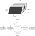
- the laminated battery cell assembly 100 includes a plurality of anode electrode plates 110 and a plurality of cathode electrode plates 120 alternately arranged, and a separator 130 arranged between any adjacent anode electrode plate 110 and cathode electrode plate 120.
- the anode electrode plate 110 includes an anode electrode plate body 111 provided with an active material and an anode electrode tab 112 without an active material layer
- the cathode electrode plate 120 includes a cathode electrode plate body 121 provided with an active material and a cathode electrode tab 122 without an active material layer.
- the laminated battery cell assembly 100 is soaked in an electrolyte, and lithium ions move between the anode and cathode of the battery cell using the electrolyte as the medium, which enables the battery cell to be charged and discharged.
- the function of the separator 130 is to allow lithium ions to pass through freely, while preventing electrons from passing through, thereby preventing a short circuit between the anode and cathode of the battery cell caused by the electrolyte.
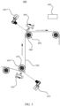
- the lamination machine 200 includes a first cutting mechanism 210, a first compounding mechanism 220, two second cutting mechanisms 230, a second compounding mechanism 240, and a lamination mechanism 250 arranged in sequence.
- the first cutting mechanism 210 is configured to cut a first electrode plate material segment from a first electrode plate material strip.
- the first compounding mechanism 220 is configured to compound a first separator material strip and a second separator material strip with two side surfaces of the first electrode plate material segment to form a primary composite material strip.
- the two second cutting mechanisms 230 are configured to cut a second electrode plate and a third electrode plate respectively from a second electrode plate material strip and a third electrode plate material strip in a one-to-one correspondence, where the second electrode plate material strip has the same polarity as the third electrode plate material strip (they can use the same material and structure) and opposite polarity as the first electrode plate material strip.
- the second compounding mechanism 240 is configured to alternately compound the second electrode plate and the third electrode plate with two side surfaces of the primary composite material strip to form a secondary composite material strip (hereinafter referred to as composite material strip for short).
- the lamination mechanism 250 is configured to laminate and cut the composite material strip to form a laminated assembly.
- the lamination mechanism 250 of the lamination machine 200 folds the composite material strip in a zigzag manner and cuts it, so as to obtain a laminated assembly. Subsequently, the subsequent production processes of battery cell assemblies, such as hot pressing and tab welding, can be carried out.
- the quality inspection of the laminated battery cell assembly is arranged after the lamination process.
- an X-ray imager is used to scan around the laminated battery cell assembly, and based on a scan image, whether the electrode plates of the laminated battery cell assembly are damaged, wrinkled, or deformed is determined.
- the working principle of the X-ray imager is as follows: When X-rays irradiate a sample, their transmission intensity is not only related to the energy of the X-rays, but also related to the material density and thickness of the sample material. A smaller material density and a thinner thickness make it easier for the X-rays to penetrate. After the X-rays irradiate the sample, the transmission intensity of the X-rays is imaged by an image receiving and converting apparatus through brightness difference in grayscale contrast, thereby forming a scan image of the X-rays.
- the separator when the composite material strip is transported in the lamination machine, the separator may be damaged, for example, damaged or wrinkled, due to presence of foreign matter on a driving roller, rolling compaction, improper tension, or other mechanical reasons.
- the separator In a laminated battery cell assembly, the separator is located between the anode electrode plate and the cathode electrode plate and has a relatively small material density, so it cannot be clearly highlighted on the scan image, which leads to the failure to detect the separator damage defect (mainly due to external factors, referred to as defect in this specification) in the preceding detection process in the related art, and in turn can easily lead to the outflow of defective battery cell assemblies, ultimately leading to battery failure and huge waste of production materials. How the production yield of laminated battery cell assemblies is improved is a technical issue that needs to be solved urgently by persons skilled in the art.
- the applicant has provided a method, apparatus, and system for defect detection of a separator of a composite material strip, an electronic device, a lamination machine, a computer-readable storage medium, and a computer program product through in-depth research, which can quickly and accurately detect defects in the separator of the composite material strip (referred to as a separator visible on the appearance of the composite material strip in this specification), thereby improving the production yield of the laminated battery cell assembly.
- the solution of the embodiments of this application utilizes computer vision technology.
- a continuous image of the composite material strip is obtained first; then at least one image segment is intercepted from the continuous image of the composite material strip; and then detection is performed on a separator region in the image segment.
- detection can be performed for defects existing in a continuous separator of the composite material strip in the lamination process, which helps relevant personnel to adjust a relevant component in the lamination machine in a timely manner.
- this application can effectively control the outflow of battery cell assemblies with defects in the separator, thereby increasing the yield of production, and reducing the waste of production materials.
- a main hardware configuration of a system 400 for defect detection of a separator of a composite material strip includes a first image acquisition unit 410, a second image acquisition unit 420, and an electronic device 490.
- the first image acquisition unit 410 is configured to acquire a continuous image of one side surface of a composite material strip 300
- the second image acquisition unit 420 is configured to acquire a continuous image of another side surface of the composite material strip 300.
- the electronic device 490 is connected to the first image acquisition unit 410 and the second image acquisition unit 420 separately, and is configured to perform defect detection on separators on two side surfaces of the composite material strip 300 based on the continuous images acquired by the first image acquisition unit 410 and the second image acquisition unit 420, and output detection results.
- the electronic device 490 may be connected to the first image acquisition unit 410 and the second image acquisition unit 420 in a wired or wireless manner.
- Main image acquisition targets of the first image acquisition unit 410 and the second image acquisition unit 420 are the composite material strip 300, and therefore the first image acquisition unit 410 and the second image acquisition unit 420 can be arranged at appropriate positions between the second compounding mechanism and lamination mechanism of the lamination machine.
- the specific types of the first image acquisition unit 410 and the second image acquisition unit 420 are not limited, and a conventional area array industrial camera or a line scan camera may be used.
- the first image acquisition unit 410 is a first line scan camera and the second image acquisition unit 420 is a second line scan camera.
- the line scan camera also known as a single-scanline camera, is used in situations where there is relative motion between a measured object and the camera, and can obtain higher resolution and larger field of view.
- An infinitely extended continuous image can be obtained theoretically by acquiring image information of a measured object in motion line by line.
- an image segment can be intercepted from the continuous image, and the electronic device can perform processing on the image segment in a timely manner or cache it for later processing.
- the system 400 further includes a first line light source 430 for illuminating an acquisition region of the first line scan camera and a second line light source 440 for illuminating an acquisition region of the second line scan camera.
- a first line light source 430 and a second line light source 440 are configured to provide illumination for their corresponding line scan cameras.
- relative installation positions of the first line light source 430 and the first line scan camera should satisfy that: A narrow bright strip formed by the first line light source 430 focusing on the composite material strip 300 is parallel to a sensor of the first line scan camera, such that the line scan camera can obtain better shooting quality.
- the specific types of the first line light source 430 and the second line light source 440 are not limited, and may be, for example, LED light sources, halogen lamps, high-frequency fluorescent lamps, or the like.
- the system 400 for defect detection of a separator of a composite material strip further includes a first support roller 450, a first encoder 470 connected to the first support roller 450, a second support roller 460, and a second encoder 480 connected to the second support roller 460.
- the first support roller 450 abuts against one side surface of the composite material strip 300, and the first encoder 470 is configured to send a pulse signal to the first line scan camera to trigger the first line scan camera to acquire images line by line.
- the second support roller 460 abuts against another side surface of the composite material strip 300, and the second encoder 480 is configured to send a pulse signal to the second line scan camera to trigger the second line scan camera to acquire images line by line.
- the encoder can convert angular displacement into pulse signal.
- the first support roller 450 is used as an example. When the first support roller 450 rotates continuously, the encoder sends one pulse signal per unit angle the first support roller 450 rotates, so as to trigger the first line scan camera to scan one side surface of the composite material strip 300.
- the first support roller 450 and the second support roller 460 can tighten the composite material strip 300, which is conducive to accurately acquiring images of the composite material strip 300, thereby improving the accuracy of defect detection.
- the image segment 500 may further include a background region 540 corresponding to the first support roller 450 and the second support roller 460.
- an acquisition region of the first line scan camera is arranged at a tangent position S1 of the composite material strip 300 and the first support roller 450 (either of the two tangent positions is acceptable), and an acquisition region of the second line scan camera is arranged at a tangent position S2 of the composite material strip 300 and the second support roller 460 (either of the two tangent positions is acceptable).
- the first support roller 450 is used as an example.
- the acquisition region of the first line scan camera is arranged at the tangent position of the composite material strip 300 and the first support roller 450, which facilitates the installation and alignment of the first line scan camera (the first image acquisition unit 410) and the first line light source 430, thereby facilitating the accurate installation of the first line scan camera and the first line light source 430, and further improving the accuracy of defect detection.
- each image segment 500 can be sequentially and continuously intercepted from the continuous images 550 for each side surface of the composite material strip 300, and then defect detection and analysis are performed on the separator of the composite material strip 300 based on the image segments 500.
- each image segment 500 may include a separator region 510, an electrode plate body region 520 surrounded by the separator region 510, and a plurality of tab protruding regions 530 protruding from the separator region 510.
- the image segment 500 may further include images of objects other than the composite material strip 300, such as an image of a support roller, corresponding to the background region 540 in the image segment 500.
- the electrode plate body region 520 may be a cathode electrode plate body region exposed on a surface of the composite material strip 300. Because the anode electrode plate is sandwiched between two separators, the anode electrode plate body region is invisible in the image segment 500, but the tab protruding region 530 protruding from the separator region 510 is visible. In some other embodiments, the electrode plate body region 520 may be an anode electrode plate body region exposed on a surface of the composite material strip 300. Because the cathode electrode plate is sandwiched between two separators, the cathode electrode plate body region is invisible in the image segment 500, but the tab protruding region 530 protruding from the separator region 510 is visible. The polarity of the electrode plate body region 520 is not specifically limited in this application.
- the image segment 500 may further include a tab-separator overlapping region 5100 connected between the electrode plate body region 520 and the tab protruding region 530.
- the entirety of the tab-separator overlapping region 5100 and tab protruding region 530 corresponds to the tab of one electrode plate on the composite material strip, to be specific, the entirety of the electrode plate body region 520, tab-separator overlapping region 5100, and tab protruding region 530 corresponds to one electrode plate on the composite material strip 300.
- a tab of an electrode plate is not provided with an active material layer, a metallic current collector is exposed at a portion of the electrode plate corresponding to the tab protruding region 530, and a metallic current collector may be exposed or a light-colored insulating layer (for example, a white insulating layer) may be provided at a portion of the electrode plate corresponding to the tab-separator overlapping region 5100.
- a grayscale of the metallic current collector or light-colored insulating layer in the image segment 500 is not lower than that of the separator region 510. Therefore, in some embodiments of this application, to simplify the computation, the tab-separator overlapping region 5100 can be included in the separator region 510, such that the separator region 510 includes the tab-separator overlapping region 5100.
- a method 600 for defect detection of a separator of a composite material strip includes the following steps S601 to S603.
- Step S601 Obtain a continuous image of the composite material strip.
- Step S602 Intercept at least one image segment from the continuous image of the composite material strip, where the image segment includes a separator region.
- Step S603 Perform detection on the separator region.
- detection can be performed for defects existing in a continuous separator of the composite material strip in the lamination process, which helps relevant personnel to adjust a relevant component in the lamination machine in a timely manner, thereby effectively controlling the outflow of battery cell assemblies with defects in the separator, increasing the yield of production, and reducing the waste of production materials.
- the image segment 500 as an intercepting unit of the continuous image 550 of the composite material strip, at least includes a separator region 510 and an electrode plate body region 520.
- the image segment 500 can further include a background region 540, a tab-separator overlapping region 5100, and a plurality of tab protruding regions 530 protruding from the separator region 510.
- the tab-separator overlapping region 5100 can be included in the separator region 510, such that the separator region 510 includes the tab-separator overlapping region 5100.
- the image segment 500 can be intercepted from the continuous image 550 shot by a line scan camera, or the image segment 500 can be obtained from an image shot by an area array camera, which is not specifically limited in this application.
- the foregoing step S601 includes: obtaining a continuous image shot by a line scan camera for each side surface of the composite material strip. In this way, the defect detection can be performed on the cathode electrode plates on two sides of the composite material strip.
- the foregoing step S602 includes: intercepting an image segment from the continuous image according to an image segmentation algorithm.
- the image segment can be intercepted from the continuous image shot by the line scan camera, so that the image segment is obtained.
- the image segmentation algorithm is not limited to a specific type, for example, may be a threshold-based segmentation algorithm, a region-based segmentation algorithm, an edge-based segmentation algorithm, or a specific theory-based segmentation algorithm. Referring to FIG.
- a threshold-based segmentation method is used to find an edge of the electrode plate body region 520 in a width direction of the composite material strip based on a grayscale difference between the electrode plate body region 520 and the separator region 510, and then segmentation is performed on the continuous image 550 in the width direction of the composite material strip based on edges of two adjacent electrode plate body regions 520 (a segmenting line can avoid the electrode plate body region 520 and be separated from the electrode plate body region 520 by several rows of pixels), to obtain the image segment 500.
- the image segment 500 includes a separator region 510 (the tab-separator overlapping region 5100 is included in the separator region 510), an electrode plate body region 520 surrounded by the separator region 510, a background region 540 adjacent to the separator region 510, and a plurality of tab protruding regions 530, where the separator region 510 is located between the left and right parts of the background region 540.
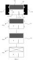
- the method for defect detection of a separator of a composite material strip may further include: extracting the separator region 510 from the image segment 500. This step may, for example, include:
- a grayscale G1 of the tab protruding region 530, a grayscale G2 of the separator region 510, a grayscale G3 of the electrode plate body region 520, and a grayscale G4 of the background region 540 satisfy G4 ⁇ G3 ⁇ G2 ⁇ G1. Therefore, in step a, the background region 540 can be removed from the image segment 500 based on the maximum grayscale threshold of the background region 540 (for example, set to 15).
- the background region 540 is removed from the image segment 500 using Blob algorithm in combination with a grayscale difference between the background region 540 and another region, to be specific, a characteristic region with a grayscale less than or equal to the maximum grayscale threshold of the background region 540 is removed.
- Blob refers to a connected component in an image
- Blob analysis is to extract and mark a connected component of a foreground/background separated binary image.
- the core concept of Blob algorithm is to find out a range of "grayscale mutation" in a region, so as to determine a size, shape, and area of the region.
- the maximum grayscale threshold of the background region 540 can be used as a grayscale threshold for binarizing the image segment 500.
- the image segment 500 is first binarized based on the maximum grayscale threshold of the background region 540 (for example, set to 15), and a characteristic region with a grayscale less than or equal to the maximum grayscale threshold of the background region 540 is extracted; then segmentation is performed on the characteristic region based on a connection operator (connection operator) of machine vision software, so as to segment non-adjacent regions to form their own connected components; after that, the connected component (corresponding to the background region 540) with an area larger than a preset area threshold is selected based on a select_shape operator (selection operator) of the machine vision software; and finally, the background region 540 is subtracted from the image segment 500 based on a difference operator (subtraction operator) of the machine vision software to obtain the first intermediate image 710.
- connection operator connection operator
- the maximum inner rectangle inscribed with the edges of the first intermediate image 710 can be computed based on an inner_rectangle1 operator (inner rectangle operator) of the machine vision software, and a region corresponding to the maximum inscribed rectangle (that is, the maximum rectangular region) can be intercepted as the second intermediate image 720.
- step c binarization processing is performed on the second intermediate image 720 first, and a characteristic region with a grayscale less than or equal to the maximum grayscale threshold of the electrode plate body region 520 (for example, set to 25) is extracted; next, an opening operation is performed on the characteristic region based on an opening_rectangle1 operator (opening operation operator) of the machine vision software to remove noise; then, segmentation is performed on the characteristic region based on the connection operator (connection operator) of the machine vision software, so as to segment non-adjacent regions to form their own connected components; and after that, a connected component with a largest area and a rectangularity greater than a rectangularity threshold (for example, the rectangularity ranges from 0 to 1, and the rectangularity threshold is set to 0.8), that is, the electrode plate body region 520, is selected based on a select_shape operator (selection operator) of the machine vision software; and finally, the electrode plate body region 520 is subtracted from the second intermediate image 720 based
- the performing detection on the separator region includes: determining whether the separator region 510 includes a suspected defect region 513.
- This step may, for example, include:
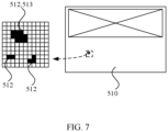
- the suspected defect region 513 can be determined using a grayscale difference between the defect region 511 and a normal region (for example, the grayscale of the electrode plate is generally less than 30, while the grayscale of the separator is generally not less than 110) and the area threshold specified according to the requirements of production process specifications.
- binarization processing is performed on the separator region 510, and a characteristic region with a grayscale smaller than a minimum grayscale threshold of the separator region 510 (for example, set to 110) is extracted; after that, as shown in FIG. 7 , segmentation is performed on the characteristic region based on a connection operator (connection operator) of the machine vision software, so as to segment the non-adjacent regions to form their own connected components; and finally, based on an area_center operator (region center operator) of the machine vision software, the connected component with an area larger than the area threshold (for example, set to 1 square millimeters), that is, the suspected defect region 513, is selected.
- a connection operator connection operator
- an area_center operator region center operator
- the performing detection on the separator region includes: determining, based on geometrical characteristic information of the suspected defect region 513, a suspected defect type corresponding to the suspected defect region 513, where the suspected defect type includes suspected damage or suspected wrinkle.
- the geometrical characteristic information of the suspected defect region 513 includes, but is not limited to, shape, size, and area. As shown in FIG. 6 , the wrinkled region 511b typically has a linear image and has an area greater than the area threshold (which can be determined by experience, for example, set to 2 square millimeters). Therefore, suspected wrinkle and suspected damage defects can be preliminarily distinguished based on this geometrical characteristic.
- the performing detection on the separator region includes:
- a plurality of separator defect samples in the separator defect sample library are traversed, and similarity comparison is performed between image information of the suspected defect region and each separator defect sample to obtain a similarity list; and then, screening is performed on the similarity list to retain a suspected defect region with a confidence coefficient greater than the confidence threshold as the determined defect region.
- a suspected defect region that does not meet the damage characteristics of the separator can be filtered out, thereby improving the accuracy of detection.
- the separator defect sample library can be divided into several sample sub-libraries based on types of defects, for example, a damaged sample sub-library and a wrinkled sample sub-library.
- the image information of the suspected defect region 513 is put into each of the sample sub-libraries in turn for similarity comparison with image information of samples therein.
- image information of the suspected defect region 513 can be put into the corresponding sample sub-library for similarity comparison.
- the image information of the suspected damaged region can be put into the damaged sample sub-library for similarity comparison with the image information of each damaged sample, so as to determine whether the suspected damaged region is a damaged region.
- the method for defect detection of a separator of a composite material strip further includes: outputting a detection result, where the detection result may include at least one of the following: positioning information of the defect region in the image segment, geometrical characteristic information of the defect region, positioning information of the image segment corresponding to the composite material strip, alarm information indicating that the separator is defective, and a defect type.
- the positioning information of the defect region in the image segment may be, for example, a frame line or an arrow indicating a position of the defect region.
- the geometrical characteristic information of the defect region includes, but is not limited to, length, width, and area of the defect region.
- the positioning information of the image segment corresponding to the composite material strip may be, for example, a shooting code corresponding to the image segment.
- the alarm information may be sound, light, or an alarm signal combining sound and light.
- the defect type is, for example, broken separator or wrinkled separator. This application does not specifically limit the content of the detection result.
- the defect type may not be analyzed, determined, or output.
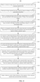
- a method 900 for defect detection of a separator of a composite material strip includes the following steps S901 to S911.
- Step S901 Obtain a continuous image shot by a line scan camera for each side surface of the composite material strip.
- Step S902 Intercept an image segment from the continuous image according to an image segmentation algorithm.
- Step S903 Remove a background region from the image segment based on a maximum grayscale threshold of the background region to obtain a first intermediate image.
- Step S904 Extract, from the first intermediate image, an image of a maximum rectangular region inscribed with edges of the first intermediate image as a second intermediate image.
- Step S905 Remove a rectangular electrode plate body region from the second intermediate image based on a maximum grayscale threshold of the electrode plate body region to obtain a separator region.
- Step S906 In response to determining that the separator region includes an abnormal pixel set, obtain at least one independently connected abnormal pixel subset based on the abnormal pixel set, where a grayscale of each pixel in the abnormal pixel set is less than a minimum grayscale threshold of the separator region.
- Step S907 For each such abnormal pixel subset, in response to determining that an area of the abnormal pixel subset is greater than an area threshold, determine that the separator region includes a suspected defect region.
- Step S908 Determine, based on geometrical characteristic information of the suspected defect region, a suspected defect type corresponding to the suspected defect region, where the suspected defect type includes suspected damage or suspected wrinkle.
- Step S909 Determine a confidence coefficient of the suspected defect region based on image information of the suspected defect region and image information of at least one separator defect sample in a separator defect sample library.
- Step S910 In response to determining that the confidence coefficient is greater than a confidence threshold, determine that the suspected defect region is a defect region.
- Step S911 Output a detection result of defect detection of the separator of the composite material strip, and send alarm information.
- detection can be performed for defects existing in a continuous separator of the composite material strip in the lamination process, which helps relevant personnel to adjust a relevant component in the lamination machine in a timely manner, thereby effectively controlling the outflow of battery cell assemblies with defects in the separator, increasing the yield of production, and reducing the waste of production materials.
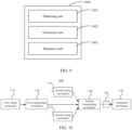
- an embodiment of this application further provides an apparatus 1000 for defect detection of a separator of a composite material strip, including:
- An embodiment of this application further provides an electronic device including at least one processor and a memory communicatively connected to the at least one processor, where the memory stores instructions executable by the at least one processor, and when the instructions are executed by the at least one processor, the at least one processor is caused to execute the foregoing method for defect detection of a separator of a composite material strip.
- the electronic device can be applied to the foregoing system 400 for defect detection of a separator of a composite material strip.
- detection can be performed for defects existing in a continuous separator of the composite material strip in the lamination process, which helps relevant personnel to adjust a relevant component in the lamination machine in a timely manner, thereby effectively controlling the outflow of battery cell assemblies with defects in the separator, increasing the yield of production, and reducing the waste of production materials.
- an embodiment of this application further provides a lamination machine 1100 including the foregoing system 400 for defect detection of a separator of a composite material strip.
- the lamination machine 1100 includes a first cutting mechanism 1110, a first compounding mechanism 1120, two second cutting mechanisms 1130, a second compounding mechanism 1140, and a lamination mechanism 1150 arranged in sequence, where the system 400 for defect detection of a separator of a composite material strip is arranged between the second compounding mechanism 1140 and the lamination mechanism 1150.
- the first cutting mechanism 1110 is configured to cut a first electrode plate material segment from a first electrode plate material strip.
- the first compounding mechanism 1120 is configured to compound a first separator material strip and a second separator material strip with two side surfaces of the first electrode plate material segment to form a primary composite material strip.
- the two second cutting mechanisms 1130 are configured to cut a second electrode plate and a third electrode plate respectively from a second electrode plate material strip and a third electrode plate material strip in a one-to-one correspondence, where the second electrode plate material strip has the same polarity as the third electrode plate material strip and opposite polarity as the first electrode plate material strip.
- the second compounding mechanism 1140 is configured to alternately compound the second electrode plate and the third electrode plate with two side surfaces of the primary composite material strip to form a secondary composite material strip (for example, the foregoing composite material strip 300).
- the lamination mechanism 1150 is configured to laminate and cut the composite material strip to form a laminated assembly.
- detection can be performed for defects existing in a continuous separator of the composite material strip, which helps relevant personnel to adjust a relevant component in the lamination machine in a timely manner, thereby effectively controlling the outflow of battery cell assemblies with defects in the separator, increasing the yield of production, and reducing the waste of production materials.
- An embodiment of this application further provides a computer-readable storage medium storing computer instructions, where the computer instructions are configured to cause a computer to execute the method for defect detection of a separator of a composite material strip according to any one of the foregoing embodiments.
- An embodiment of this application further provides a computer program product including a computer program, where when the computer program is executed by a processor, the method for defect detection of a separator of a composite material strip according to any one of the foregoing embodiments is implemented.
Landscapes
- Engineering & Computer Science (AREA)
- Theoretical Computer Science (AREA)
- General Physics & Mathematics (AREA)
- Physics & Mathematics (AREA)
- Computer Vision & Pattern Recognition (AREA)
- Chemical & Material Sciences (AREA)
- Multimedia (AREA)
- Health & Medical Sciences (AREA)
- Quality & Reliability (AREA)
- General Health & Medical Sciences (AREA)
- Chemical Kinetics & Catalysis (AREA)
- Manufacturing & Machinery (AREA)
- General Chemical & Material Sciences (AREA)
- Electrochemistry (AREA)
- Computing Systems (AREA)
- Software Systems (AREA)
- Databases & Information Systems (AREA)
- Artificial Intelligence (AREA)
- Evolutionary Computation (AREA)
- Medical Informatics (AREA)
- Materials Engineering (AREA)
- Life Sciences & Earth Sciences (AREA)
- Analytical Chemistry (AREA)
- Biochemistry (AREA)
- Immunology (AREA)
- Pathology (AREA)
- Investigating Materials By The Use Of Optical Means Adapted For Particular Applications (AREA)
Abstract
Description
- This application refers to
China Patent Application No. 202210405574.1, filed on April 18, 2022 - This application relates to the technical field of battery production inspection, and specifically, to a method, apparatus, and system for defect detection of a separator of a composite material strip, an electronic device, a lamination machine, a computer-readable storage medium, and a computer program product.
- In the related art, a rechargeable battery (a battery that can be used continuously by activating the active material through charging after the battery is discharged, also known as a secondary battery) includes a battery box and a plurality of battery cells that are combined in series and/or parallel inside the battery box. The battery cell is the smallest unit that provides energy source in the battery. A battery cell assembly is a key component in which electrochemical reactions take place in the battery cell, and its main structure includes an anode electrode plate, a cathode electrode plate, and a separator for separating the anode electrode plate from the cathode electrode plate.
- According to the production process, battery cell assemblies can be classified into wound battery cell assemblies and laminated battery cell assemblies. The compounding process of the lamination material strip may cause damage to the battery cell assembly, so how the production yield of laminated battery cell assemblies is improved is a technical issue that needs to be solved urgently by persons skilled in the art.
- This application is intended to resolve at least one of the technical issues in the prior art. To this end, an objective of this application is to provide a method, apparatus, and system for defect detection of a separator of a composite material strip, an electronic device, a lamination machine, a computer-readable storage medium, and a computer program product.
- According to an aspect of this application, a method for defect detection of a separator of a composite material strip is provided, where the method includes: obtaining a continuous image of the composite material strip; intercepting at least one image segment from the continuous image of the composite material strip, where the image segment includes a separator region; and performing detection on the separator region.
- According to the solution of this embodiment of this application, detection can be performed for defects existing in a continuous separator of the composite material strip in the lamination process, which helps relevant personnel to adjust a relevant component in the lamination machine in a timely manner, thereby effectively controlling the outflow of battery cell assemblies with defects in the separator, increasing the yield of production, and reducing the waste of production materials.
- In some embodiments, the image segment further includes an electrode plate body region surrounded by the separator region, a plurality of tab protruding regions, and a background region adjacent to the separator region, and the method further includes: extracting the separator region from the image segment.
- In some embodiments, the extracting the separator region from the image segment includes: removing a background region from the image segment based on a maximum grayscale threshold of the background region to obtain a first intermediate image; extracting, from the first intermediate image, an image of a maximum rectangular region inscribed with edges of the first intermediate image as a second intermediate image; and removing a rectangular electrode plate body region from the second intermediate image based on a maximum grayscale threshold of the electrode plate body region to obtain the separator region. According to the solution of this embodiment, the extraction of the separator region can be realized.
- In some embodiments, the performing detection on the separator region includes: determining whether the separator region includes a suspected defect region.
- In some embodiments, the determining whether the separator region includes a suspected defect region includes: in response to determining that the separator region includes an abnormal pixel set, obtaining at least one independently connected abnormal pixel subset based on the abnormal pixel set, where a grayscale of each pixel in the abnormal pixel set is less than a minimum grayscale threshold of the separator region; and for each such abnormal pixel subset, in response to determining that an area of the abnormal pixel subset is greater than an area threshold, determining that the separator region includes the suspected defect region. According to the solution of this embodiment, the suspected defect region can be identified.
- In some embodiments, the performing detection on the separator region includes: determining a suspected defect type corresponding to the suspected defect region based on geometrical characteristic information of the suspected defect region, where the suspected defect type includes suspected damage or suspected wrinkle. In this embodiment, the suspected defect type of the suspected defect region such as suspected damage or suspected wrinkle can be further determined.
- In some embodiments, the performing detection on the separator region includes: determining a confidence coefficient of the suspected defect region based on image information of the suspected defect region and image information of at least one separator defect sample in a separator defect sample library; and in response to determining that the confidence coefficient is greater than a confidence threshold, determining that the suspected defect region is a defect region. According to the solution of this embodiment, whether the suspected defect region is a defect region can be accurately determined.
- In some embodiments, the obtaining a continuous image of the composite material strip includes: obtaining a continuous image shot by a line scan camera for each side surface of the composite material strip. In this way, the defect detection can be performed for the separators on both sides of the composite material strip.
- In some embodiments, the method further includes: outputting a detection result, where the detection result includes at least one of the following: positioning information of the defect region in the image segment, geometrical characteristic information of the defect region, positioning information of the image segment corresponding to the composite material strip, alarm information indicating that the separator is defective, and a defect type, where the defect type includes damage or wrinkle. The foregoing content of the detection result is helpful for the relevant personnel to know about the specific situation of the defects in the separator, so that the relevant component in the lamination machine can be adjusted in a timely manner.
- According to an aspect of this application, an apparatus for defect detection of a separator of a composite material strip is provided, where the apparatus includes: an obtaining unit, configured to obtain a continuous image of the composite material strip; an extraction unit, configured to intercept at least one image segment from the continuous image of the composite material strip, where the image segment includes a separator region; and a detection unit, configured to perform detection on the separator region. The solution of this embodiment can achieve the same technical effect as the above method.
- According to an aspect of this application, an electronic device is provided, where the electronic device includes at least one processor and a memory communicatively connected to the at least one processor, where the memory stores instructions executable by the at least one processor, and when the instructions are executed by the at least one processor, the at least one processor is caused to execute the foregoing method.
- According to one an aspect of this application, a system for defect detection of a separator of a composite material strip is provided, including: a first image acquisition unit, configured to acquire a continuous image of one side surface of the composite material strip; a second image acquisition unit, configured to acquire a continuous image of another side surface of the composite material strip; and the electronic device according to the foregoing aspect, connected to the first image acquisition unit and the second image acquisition unit separately. According to the solution of this embodiment, detection can be performed for defects existing in a continuous separator of the composite material strip in the lamination process, which helps relevant personnel to adjust a relevant component in the lamination machine in a timely manner, thereby effectively controlling the outflow of defective battery cell assemblies, increasing the yield of production, and reducing the waste of production materials.
- In some embodiments, the first image acquisition unit is a first line scan camera and the second image acquisition unit is a second line scan camera; and the system further includes a first line light source for illuminating an acquisition region of the first line scan camera and a second line light source for illuminating an acquisition region of the second line scan camera. The line scan camera is more suitable for situations where there is relative motion between a measured object and the camera and can obtain higher resolution and larger field of view. The line light source is used to provide illumination for the line scan camera.
- In some embodiments, the system according to the foregoing aspect further includes a first support roller and a first encoder connected to the first support roller, where the first support roller abuts against one side surface of the composite material strip, and the first encoder is configured to send a pulse signal to the first line scan camera to trigger the first line scan camera to acquire images line by line; and a second support roller and a second encoder connected to the second support roller, where the second support roller abuts against another side surface of the composite material strip, and the second encoder is configured to send a pulse signal to the second line scan camera to trigger the second line scan camera to acquire images line by line. The first support roller and the second support roller can tighten the composite material strip, which is conducive to accurately acquiring images of the composite material strip, thereby improving the accuracy of defect detection.
- In some embodiments, the acquisition region of the first line scan camera is arranged at a tangent position of the composite material strip and the first support roller; and the acquisition region of the second line scan camera is arranged at a tangent position of the composite material strip and the second support roller. This solution facilitates the installation and alignment of the line scan camera and the line light source, thereby facilitating the accurate installation of the line scan camera and the line light source, and further helping to improve the accuracy of defect detection.
- According to an aspect of this application, a lamination machine is provided, including the system according to the foregoing aspect. In the lamination process of the lamination machine, detection is performed for the defects existing in the separator of the continuous composite material strip, which helps the relevant personnel to adjust the relevant component in the lamination machine in a timely manner, thereby increasing the yield of production.
- According to an aspect of this application, a computer-readable storage medium storing computer instructions is provided, where the computer instructions are used to cause a computer to execute the method according to foregoing aspect.
- According to an aspect of this application, a computer program product is provided, including a computer program, where when the computer program is executed by a processor, the method according to the foregoing aspect is implemented.
- According to the foregoing embodiments of this application, detection can be performed for defects existing in a continuous separator of the composite material strip in the lamination process, which helps relevant personnel to adjust a relevant component in the lamination machine in a timely manner, thereby effectively controlling the outflow of battery cell assemblies with defects in the separator, increasing the yield of production, and reducing the waste of production materials.
- The foregoing description is merely an overview of the technical solution of this application. For a better understanding of the technical means in this application such that they can be implemented according to the content of the specification, and to make the above and other objectives, features and advantages of this application more obvious and easier to understand, the following describes specific embodiments of this application.
- In the accompanying drawings, unless otherwise specified, the same reference signs in a plurality of accompanying drawings denote the same or similar components or elements. The accompanying drawings are not necessarily drawn to scale. It should be understood that these accompanying drawings merely describe some embodiments disclosed in this application, and should not be construed as a limitation on the scope of this application. To describe the technical solutions of the embodiments of this application more clearly, the following briefly describes the accompanying drawings required for describing the embodiments of this application. Apparently, the accompanying drawings described below show merely some embodiments of this application, and persons of ordinary skill in the art may still derive other drawings from the accompanying drawings without creative efforts.
-
FIG. 1 is a schematic diagram of a disassembled structure of a laminated battery cell assembly; -
FIG. 2 is a structural block diagram of a lamination machine in the related art; -
FIG. 3 is a schematic structural diagram of a system for defect detection of a separator of a composite material strip according to some embodiments of this application; -
FIG. 4 is a schematic diagram of an image segment according to some embodiments of this application; -
FIG. 5 is a schematic flowchart of a method for defect detection of a separator of a composite material strip according to some embodiments of this application; -
FIG. 6 is a schematic flowchart of extracting a separator region from an image segment according to some embodiments of this application; -
FIG. 7 is a schematic diagram of a suspected defect region in a separator region according to some embodiments of this application; -
FIG. 8 is a schematic flowchart of a method for defect detection of a separator of a composite material strip according to some embodiments of this application; -
FIG. 9 is a structural block diagram of an apparatus for defect detection of a separator of a composite material strip according to some embodiments of this application; and -
FIG. 10 is a structural block diagram of a lamination machine according to some embodiments of this application. -
- 100: laminated battery cell assembly; 110: anode electrode plate; 111: anode electrode plate body; 112: anode electrode tab;
- 120: cathode electrode plate; 121: cathode electrode plate body; 122: cathode electrode tab; 130: separator; 200: lamination machine;
- 210: first cutting mechanism; 220: first compounding mechanism; 230: second cutting mechanism; 240: second compounding mechanism;
- 250: lamination mechanism; 400: system; 410: first image acquisition unit; 420: second image acquisition unit;
- 430: first line light source; 440: second line light source; 450: first support roller; 460: second support roller;
- 470: first encoder; 480: second encoder; 490: electronic device; 550: continuous image; 500: image segment;
- 510: separator region; 511: defect region; 511a: damaged region; 511b: wrinkled region; 520: electrode plate body region;
- 530: tab protruding region; 540: background region; 5100: tab-separator overlapping region; 710: first intermediate image;
- 720: second intermediate image; 512: abnormal pixel subset; 513: suspected defect region; 1001: obtaining unit;
- 1002: extraction unit; 1003: detection unit; 1100: lamination machine; 1110: first cutting mechanism; 300: composite material strip;
- 1120: first compounding mechanism; 1130: second cutting mechanism; 1140: second compounding mechanism; and 1150: lamination mechanism.
- The following describes in detail the embodiments of technical solutions of this application with reference to the accompanying drawings. The following embodiments are merely intended for a clearer description of the technical solutions of this application and therefore are used as just examples which do not constitute any limitations on the protection scope of this application.
- Unless otherwise defined, all technical and scientific terms used herein shall have the same meanings as commonly understood by those skilled in the art to which this application relates. The terms used herein are intended to merely describe the specific embodiments rather than to limit this application. The terms "include", "comprise", and "have" and any other variations thereof in the specification, claims and brief description of drawings of this application are intended to cover non-exclusive inclusions.
- In the description of the embodiments of this application, the technical terms "first", "second" and the like are merely intended to distinguish between different objects, and shall not be understood as any indication or implication of relative importance or any implicit indication of the number, sequence or primary-secondary relationship of the technical features indicated. In the description of this application, "a plurality of" means at least two unless otherwise specifically stated.
- In this specification, reference to "embodiment" means that specific features, structures or characteristics described with reference to the embodiment may be incorporated in at least one embodiment of this application. The word "embodiment" appearing in various places in the specification does not necessarily refer to the same embodiment or an independent or alternative embodiment that is exclusive of other embodiments. It is explicitly or implicitly understood by persons skilled in the art that the embodiments described herein may be combined with other embodiments.
- In the description of the embodiments of this application, the term "and/or" is only an associative relationship for describing associated objects, indicating that three relationships may be present. For example, A and/or B may indicate the following three cases: presence of only A, presence of both A and B, and presence of only B. In addition, the character "/" in this specification generally indicates an "or" relationship between contextually associated objects.
- In the description of the embodiments of this application, the term "a plurality of" means more than two (inclusive). Similarly, "a plurality of groups" means more than two (inclusive) groups, and "a plurality of pieces" means more than two (inclusive) pieces.
- In the description of the embodiments of this application, the orientations or positional relationships indicated by the technical terms "center", "longitudinal", "transverse", "length", "width", "thickness", "upper", "lower", "front", "rear", "left", "right", "vertical", "horizontal", "top", "bottom", "inside", "outside", "clockwise", "counterclockwise", "axial", "radial", "circumferential", and the like are based on the orientations or positional relationships as shown in the accompanying drawings. These terms are merely for ease and brevity of description of the embodiments of this application rather than indicating or implying that the means or components mentioned must have specific orientations or must be constructed or manipulated according to specific orientations, and therefore shall not be construed as any limitations on embodiments of this application.
- In the description of the embodiments of this application, unless otherwise specified and defined explicitly, the technical terms "mounting", "connection", "joining", and "fasten" should be understood in their general senses. For example, they may refer to a fixed connection, a detachable connection, or an integral connection, may refer to a mechanical connection or an electrical connection, and may refer to a direct connection, an indirect connection via an intermediate medium, an internal communication between two elements, or an interaction between two elements. Persons of ordinary skill in the art can understand specific meanings of these terms in this application as appropriate to specific situations.
- As shown in
FIG. 1 , the laminatedbattery cell assembly 100 includes a plurality of anode electrode plates 110 and a plurality of cathode electrode plates 120 alternately arranged, and aseparator 130 arranged between any adjacent anode electrode plate 110 and cathode electrode plate 120. The anode electrode plate 110 includes an anode electrode plate body 111 provided with an active material and an anode electrode tab 112 without an active material layer, and the cathode electrode plate 120 includes a cathode electrode plate body 121 provided with an active material and a cathode electrode tab 122 without an active material layer. Inside a lithium-ion battery cell (hereinafter referred to as a battery cell), the laminatedbattery cell assembly 100 is soaked in an electrolyte, and lithium ions move between the anode and cathode of the battery cell using the electrolyte as the medium, which enables the battery cell to be charged and discharged. The function of theseparator 130 is to allow lithium ions to pass through freely, while preventing electrons from passing through, thereby preventing a short circuit between the anode and cathode of the battery cell caused by the electrolyte. - The lamination process of laminated battery cell assemblies is mainly carried out in a lamination machine. As shown in
FIG. 2 , in the related art, thelamination machine 200 includes afirst cutting mechanism 210, afirst compounding mechanism 220, twosecond cutting mechanisms 230, asecond compounding mechanism 240, and alamination mechanism 250 arranged in sequence. Thefirst cutting mechanism 210 is configured to cut a first electrode plate material segment from a first electrode plate material strip. Thefirst compounding mechanism 220 is configured to compound a first separator material strip and a second separator material strip with two side surfaces of the first electrode plate material segment to form a primary composite material strip. The twosecond cutting mechanisms 230 are configured to cut a second electrode plate and a third electrode plate respectively from a second electrode plate material strip and a third electrode plate material strip in a one-to-one correspondence, where the second electrode plate material strip has the same polarity as the third electrode plate material strip (they can use the same material and structure) and opposite polarity as the first electrode plate material strip. Thesecond compounding mechanism 240 is configured to alternately compound the second electrode plate and the third electrode plate with two side surfaces of the primary composite material strip to form a secondary composite material strip (hereinafter referred to as composite material strip for short). Thelamination mechanism 250 is configured to laminate and cut the composite material strip to form a laminated assembly. - The
lamination mechanism 250 of thelamination machine 200 folds the composite material strip in a zigzag manner and cuts it, so as to obtain a laminated assembly. Subsequently, the subsequent production processes of battery cell assemblies, such as hot pressing and tab welding, can be carried out. - In the related art, the quality inspection of the laminated battery cell assembly is arranged after the lamination process. Generally, an X-ray imager is used to scan around the laminated battery cell assembly, and based on a scan image, whether the electrode plates of the laminated battery cell assembly are damaged, wrinkled, or deformed is determined. The working principle of the X-ray imager is as follows: When X-rays irradiate a sample, their transmission intensity is not only related to the energy of the X-rays, but also related to the material density and thickness of the sample material. A smaller material density and a thinner thickness make it easier for the X-rays to penetrate. After the X-rays irradiate the sample, the transmission intensity of the X-rays is imaged by an image receiving and converting apparatus through brightness difference in grayscale contrast, thereby forming a scan image of the X-rays.
- The applicant of this application has noticed that when the composite material strip is transported in the lamination machine, the separator may be damaged, for example, damaged or wrinkled, due to presence of foreign matter on a driving roller, rolling compaction, improper tension, or other mechanical reasons. In a laminated battery cell assembly, the separator is located between the anode electrode plate and the cathode electrode plate and has a relatively small material density, so it cannot be clearly highlighted on the scan image, which leads to the failure to detect the separator damage defect (mainly due to external factors, referred to as defect in this specification) in the preceding detection process in the related art, and in turn can easily lead to the outflow of defective battery cell assemblies, ultimately leading to battery failure and huge waste of production materials. How the production yield of laminated battery cell assemblies is improved is a technical issue that needs to be solved urgently by persons skilled in the art.
- In view of the above technical issues found, the applicant has provided a method, apparatus, and system for defect detection of a separator of a composite material strip, an electronic device, a lamination machine, a computer-readable storage medium, and a computer program product through in-depth research, which can quickly and accurately detect defects in the separator of the composite material strip (referred to as a separator visible on the appearance of the composite material strip in this specification), thereby improving the production yield of the laminated battery cell assembly.
- The solution of the embodiments of this application utilizes computer vision technology. A continuous image of the composite material strip is obtained first; then at least one image segment is intercepted from the continuous image of the composite material strip; and then detection is performed on a separator region in the image segment. According to the solution of the embodiments of this application, detection can be performed for defects existing in a continuous separator of the composite material strip in the lamination process, which helps relevant personnel to adjust a relevant component in the lamination machine in a timely manner. Compared with the related art, this application can effectively control the outflow of battery cell assemblies with defects in the separator, thereby increasing the yield of production, and reducing the waste of production materials.
- As shown in
FIG. 3 , a main hardware configuration of asystem 400 for defect detection of a separator of a composite material strip according to some embodiments of this application includes a firstimage acquisition unit 410, a secondimage acquisition unit 420, and anelectronic device 490. The firstimage acquisition unit 410 is configured to acquire a continuous image of one side surface of acomposite material strip 300, and the secondimage acquisition unit 420 is configured to acquire a continuous image of another side surface of thecomposite material strip 300. Theelectronic device 490 is connected to the firstimage acquisition unit 410 and the secondimage acquisition unit 420 separately, and is configured to perform defect detection on separators on two side surfaces of thecomposite material strip 300 based on the continuous images acquired by the firstimage acquisition unit 410 and the secondimage acquisition unit 420, and output detection results. - The
electronic device 490 may be connected to the firstimage acquisition unit 410 and the secondimage acquisition unit 420 in a wired or wireless manner. Main image acquisition targets of the firstimage acquisition unit 410 and the secondimage acquisition unit 420 are thecomposite material strip 300, and therefore the firstimage acquisition unit 410 and the secondimage acquisition unit 420 can be arranged at appropriate positions between the second compounding mechanism and lamination mechanism of the lamination machine. - The specific types of the first
image acquisition unit 410 and the secondimage acquisition unit 420 are not limited, and a conventional area array industrial camera or a line scan camera may be used. In some embodiments of this application, the firstimage acquisition unit 410 is a first line scan camera and the secondimage acquisition unit 420 is a second line scan camera. - The line scan camera, also known as a single-scanline camera, is used in situations where there is relative motion between a measured object and the camera, and can obtain higher resolution and larger field of view. An infinitely extended continuous image can be obtained theoretically by acquiring image information of a measured object in motion line by line. Through the intelligent processing of software, an image segment can be intercepted from the continuous image, and the electronic device can perform processing on the image segment in a timely manner or cache it for later processing.
- In some embodiments, the
system 400 further includes a firstline light source 430 for illuminating an acquisition region of the first line scan camera and a secondline light source 440 for illuminating an acquisition region of the second line scan camera. A firstline light source 430 and a secondline light source 440 are configured to provide illumination for their corresponding line scan cameras. For example, relative installation positions of the firstline light source 430 and the first line scan camera should satisfy that: A narrow bright strip formed by the firstline light source 430 focusing on thecomposite material strip 300 is parallel to a sensor of the first line scan camera, such that the line scan camera can obtain better shooting quality. The specific types of the firstline light source 430 and the secondline light source 440 are not limited, and may be, for example, LED light sources, halogen lamps, high-frequency fluorescent lamps, or the like. - As shown in
FIG. 3 , in some embodiments, thesystem 400 for defect detection of a separator of a composite material strip further includes afirst support roller 450, afirst encoder 470 connected to thefirst support roller 450, asecond support roller 460, and asecond encoder 480 connected to thesecond support roller 460. Thefirst support roller 450 abuts against one side surface of thecomposite material strip 300, and thefirst encoder 470 is configured to send a pulse signal to the first line scan camera to trigger the first line scan camera to acquire images line by line. Thesecond support roller 460 abuts against another side surface of thecomposite material strip 300, and thesecond encoder 480 is configured to send a pulse signal to the second line scan camera to trigger the second line scan camera to acquire images line by line. - The encoder can convert angular displacement into pulse signal. The
first support roller 450 is used as an example. When thefirst support roller 450 rotates continuously, the encoder sends one pulse signal per unit angle thefirst support roller 450 rotates, so as to trigger the first line scan camera to scan one side surface of thecomposite material strip 300. - The
first support roller 450 and thesecond support roller 460 can tighten thecomposite material strip 300, which is conducive to accurately acquiring images of thecomposite material strip 300, thereby improving the accuracy of defect detection. As shown inFIG. 4 , theimage segment 500 may further include abackground region 540 corresponding to thefirst support roller 450 and thesecond support roller 460. - In some embodiments of this application, as shown in
FIG. 3 , an acquisition region of the first line scan camera is arranged at a tangent position S1 of thecomposite material strip 300 and the first support roller 450 (either of the two tangent positions is acceptable), and an acquisition region of the second line scan camera is arranged at a tangent position S2 of thecomposite material strip 300 and the second support roller 460 (either of the two tangent positions is acceptable). Thefirst support roller 450 is used as an example. The acquisition region of the first line scan camera is arranged at the tangent position of thecomposite material strip 300 and thefirst support roller 450, which facilitates the installation and alignment of the first line scan camera (the first image acquisition unit 410) and the firstline light source 430, thereby facilitating the accurate installation of the first line scan camera and the firstline light source 430, and further improving the accuracy of defect detection. - As shown in
FIG. 4 , in the embodiments of this application,image segments 500 can be sequentially and continuously intercepted from thecontinuous images 550 for each side surface of thecomposite material strip 300, and then defect detection and analysis are performed on the separator of thecomposite material strip 300 based on theimage segments 500. As an interception unit, eachimage segment 500 may include aseparator region 510, an electrodeplate body region 520 surrounded by theseparator region 510, and a plurality oftab protruding regions 530 protruding from theseparator region 510. In addition, theimage segment 500 may further include images of objects other than thecomposite material strip 300, such as an image of a support roller, corresponding to thebackground region 540 in theimage segment 500. - In some embodiments, the electrode
plate body region 520 may be a cathode electrode plate body region exposed on a surface of thecomposite material strip 300. Because the anode electrode plate is sandwiched between two separators, the anode electrode plate body region is invisible in theimage segment 500, but thetab protruding region 530 protruding from theseparator region 510 is visible. In some other embodiments, the electrodeplate body region 520 may be an anode electrode plate body region exposed on a surface of thecomposite material strip 300. Because the cathode electrode plate is sandwiched between two separators, the cathode electrode plate body region is invisible in theimage segment 500, but thetab protruding region 530 protruding from theseparator region 510 is visible. The polarity of the electrodeplate body region 520 is not specifically limited in this application. - It should be noted that the
image segment 500 may further include a tab-separator overlapping region 5100 connected between the electrodeplate body region 520 and thetab protruding region 530. The entirety of the tab-separator overlapping region 5100 andtab protruding region 530 corresponds to the tab of one electrode plate on the composite material strip, to be specific, the entirety of the electrodeplate body region 520, tab-separator overlapping region 5100, andtab protruding region 530 corresponds to one electrode plate on thecomposite material strip 300. Generally, a tab of an electrode plate is not provided with an active material layer, a metallic current collector is exposed at a portion of the electrode plate corresponding to thetab protruding region 530, and a metallic current collector may be exposed or a light-colored insulating layer (for example, a white insulating layer) may be provided at a portion of the electrode plate corresponding to the tab-separator overlapping region 5100. Generally, a grayscale of the metallic current collector or light-colored insulating layer in theimage segment 500 is not lower than that of theseparator region 510. Therefore, in some embodiments of this application, to simplify the computation, the tab-separator overlapping region 5100 can be included in theseparator region 510, such that theseparator region 510 includes the tab-separator overlapping region 5100. - As shown in
FIG. 5 , amethod 600 for defect detection of a separator of a composite material strip according to some embodiments of this application includes the following steps S601 to S603. - Step S601: Obtain a continuous image of the composite material strip.
- Step S602: Intercept at least one image segment from the continuous image of the composite material strip, where the image segment includes a separator region.
- Step S603: Perform detection on the separator region.
- According to the
method 600 of these embodiments of this application, with computer vision technology, detection can be performed for defects existing in a continuous separator of the composite material strip in the lamination process, which helps relevant personnel to adjust a relevant component in the lamination machine in a timely manner, thereby effectively controlling the outflow of battery cell assemblies with defects in the separator, increasing the yield of production, and reducing the waste of production materials. - As shown in
FIG. 4 , theimage segment 500, as an intercepting unit of thecontinuous image 550 of the composite material strip, at least includes aseparator region 510 and an electrodeplate body region 520. In addition, theimage segment 500 can further include abackground region 540, a tab-separator overlapping region 5100, and a plurality oftab protruding regions 530 protruding from theseparator region 510. In some embodiments of this application, to simplify the computation, the tab-separator overlapping region 5100 can be included in theseparator region 510, such that theseparator region 510 includes the tab-separator overlapping region 5100. - In these embodiments of this application, the
image segment 500 can be intercepted from thecontinuous image 550 shot by a line scan camera, or theimage segment 500 can be obtained from an image shot by an area array camera, which is not specifically limited in this application. - In some embodiments, the foregoing step S601 includes: obtaining a continuous image shot by a line scan camera for each side surface of the composite material strip. In this way, the defect detection can be performed on the cathode electrode plates on two sides of the composite material strip.
- In some embodiments of this application, the foregoing step S602 includes: intercepting an image segment from the continuous image according to an image segmentation algorithm. In these embodiments, based on an image segmentation algorithm, the image segment can be intercepted from the continuous image shot by the line scan camera, so that the image segment is obtained. The image segmentation algorithm is not limited to a specific type, for example, may be a threshold-based segmentation algorithm, a region-based segmentation algorithm, an edge-based segmentation algorithm, or a specific theory-based segmentation algorithm. Referring to
FIG. 4 , in some embodiments of this application, a threshold-based segmentation method is used to find an edge of the electrodeplate body region 520 in a width direction of the composite material strip based on a grayscale difference between the electrodeplate body region 520 and theseparator region 510, and then segmentation is performed on thecontinuous image 550 in the width direction of the composite material strip based on edges of two adjacent electrode plate body regions 520 (a segmenting line can avoid the electrodeplate body region 520 and be separated from the electrodeplate body region 520 by several rows of pixels), to obtain theimage segment 500. - In some embodiments of this application, as shown in
FIG. 6 , theimage segment 500 includes a separator region 510 (the tab-separator overlapping region 5100 is included in the separator region 510), an electrodeplate body region 520 surrounded by theseparator region 510, abackground region 540 adjacent to theseparator region 510, and a plurality oftab protruding regions 530, where theseparator region 510 is located between the left and right parts of thebackground region 540. The method for defect detection of a separator of a composite material strip may further include: extracting theseparator region 510 from theimage segment 500. This step may, for example, include: - step a: removing the
background region 540 from theimage segment 500 based on a maximum grayscale threshold of thebackground region 540 to obtain a firstintermediate image 710; - step b: extracting, from the first
intermediate image 710, an image of a maximum rectangular region inscribed with the edges of the first intermediate image as a secondintermediate image 720; and - step c: removing the rectangular electrode
plate body region 520 from the secondintermediate image 720 based on a maximum grayscale threshold of the electrodeplate body region 520 to obtain theseparator region 510. - As shown in
FIG. 6 , in theimage segment 500, a grayscale G1 of thetab protruding region 530, a grayscale G2 of theseparator region 510, a grayscale G3 of the electrodeplate body region 520, and a grayscale G4 of thebackground region 540 satisfy G4 < G3 < G2 ≤ G1. Therefore, in step a, thebackground region 540 can be removed from theimage segment 500 based on the maximum grayscale threshold of the background region 540 (for example, set to 15). - In some embodiments, the
background region 540 is removed from theimage segment 500 using Blob algorithm in combination with a grayscale difference between thebackground region 540 and another region, to be specific, a characteristic region with a grayscale less than or equal to the maximum grayscale threshold of thebackground region 540 is removed. In computer vision, Blob refers to a connected component in an image, and Blob analysis is to extract and mark a connected component of a foreground/background separated binary image. The core concept of Blob algorithm is to find out a range of "grayscale mutation" in a region, so as to determine a size, shape, and area of the region. The maximum grayscale threshold of thebackground region 540 can be used as a grayscale threshold for binarizing theimage segment 500. - In some embodiments of this application, in step a, the
image segment 500 is first binarized based on the maximum grayscale threshold of the background region 540 (for example, set to 15), and a characteristic region with a grayscale less than or equal to the maximum grayscale threshold of thebackground region 540 is extracted; then segmentation is performed on the characteristic region based on a connection operator (connection operator) of machine vision software, so as to segment non-adjacent regions to form their own connected components; after that, the connected component (corresponding to the background region 540) with an area larger than a preset area threshold is selected based on a select_shape operator (selection operator) of the machine vision software; and finally, thebackground region 540 is subtracted from theimage segment 500 based on a difference operator (subtraction operator) of the machine vision software to obtain the firstintermediate image 710. - In some embodiments of this application, in step b, the maximum inner rectangle inscribed with the edges of the first
intermediate image 710 can be computed based on an inner_rectangle1 operator (inner rectangle operator) of the machine vision software, and a region corresponding to the maximum inscribed rectangle (that is, the maximum rectangular region) can be intercepted as the secondintermediate image 720. - In some embodiments of this application, in step c, binarization processing is performed on the second
intermediate image 720 first, and a characteristic region with a grayscale less than or equal to the maximum grayscale threshold of the electrode plate body region 520 (for example, set to 25) is extracted; next, an opening operation is performed on the characteristic region based on an opening_rectangle1 operator (opening operation operator) of the machine vision software to remove noise; then, segmentation is performed on the characteristic region based on the connection operator (connection operator) of the machine vision software, so as to segment non-adjacent regions to form their own connected components; and after that, a connected component with a largest area and a rectangularity greater than a rectangularity threshold (for example, the rectangularity ranges from 0 to 1, and the rectangularity threshold is set to 0.8), that is, the electrodeplate body region 520, is selected based on a select_shape operator (selection operator) of the machine vision software; and finally, the electrodeplate body region 520 is subtracted from the secondintermediate image 720 based on a difference operator (subtraction operator) of the machine vision software to obtain theseparator region 510. - As shown in
FIG. 5 andFIG. 7 , in some embodiments of this application, the performing detection on the separator region includes: determining whether theseparator region 510 includes a suspected defect region 513. This step may, for example, include: - in response to determining that the
separator region 510 includes an abnormal pixel set, obtaining at least one independently connectedabnormal pixel subset 512 based on the abnormal pixel set, where a grayscale of each pixel in the abnormal pixel set is less than a minimum grayscale threshold of theseparator region 510; and - for each such
abnormal pixel subset 512, in response to determining that an area of theabnormal pixel subset 512 is greater than an area threshold, determining that theseparator region 510 includes the suspected defect region 513. The area threshold can be determined according to the requirements of battery production process specifications. - As shown in
FIG. 6 , after the separator of the composite material strip is damaged, the electrode plate below is exposed, which causes the grayscale of the image in the damaged region 511a to decrease, and after the separator of the composite material strip is wrinkled, the grayscale of the image in the wrinkled region 511b is also decreased. Therefore, the suspected defect region 513 can be determined using a grayscale difference between the defect region 511 and a normal region (for example, the grayscale of the electrode plate is generally less than 30, while the grayscale of the separator is generally not less than 110) and the area threshold specified according to the requirements of production process specifications. - In some embodiments, binarization processing is performed on the
separator region 510, and a characteristic region with a grayscale smaller than a minimum grayscale threshold of the separator region 510 (for example, set to 110) is extracted; after that, as shown inFIG. 7 , segmentation is performed on the characteristic region based on a connection operator (connection operator) of the machine vision software, so as to segment the non-adjacent regions to form their own connected components; and finally, based on an area_center operator (region center operator) of the machine vision software, the connected component with an area larger than the area threshold (for example, set to 1 square millimeters), that is, the suspected defect region 513, is selected. - In some embodiments, the performing detection on the separator region includes: determining, based on geometrical characteristic information of the suspected defect region 513, a suspected defect type corresponding to the suspected defect region 513, where the suspected defect type includes suspected damage or suspected wrinkle.
- The geometrical characteristic information of the suspected defect region 513 includes, but is not limited to, shape, size, and area. As shown in
FIG. 6 , the wrinkled region 511b typically has a linear image and has an area greater than the area threshold (which can be determined by experience, for example, set to 2 square millimeters). Therefore, suspected wrinkle and suspected damage defects can be preliminarily distinguished based on this geometrical characteristic. - In some embodiments of this application, the performing detection on the separator region includes:
- determining a confidence coefficient of the suspected defect region based on image information of the suspected defect region and image information of at least one separator defect sample in a separator defect sample library; and
- in response to determining that the confidence coefficient is greater than a confidence threshold, determining that the suspected defect region is a defect region.
- For example, in some embodiments, first, a plurality of separator defect samples in the separator defect sample library are traversed, and similarity comparison is performed between image information of the suspected defect region and each separator defect sample to obtain a similarity list; and then, screening is performed on the similarity list to retain a suspected defect region with a confidence coefficient greater than the confidence threshold as the determined defect region. With this step, a suspected defect region that does not meet the damage characteristics of the separator can be filtered out, thereby improving the accuracy of detection.
- The separator defect sample library can be divided into several sample sub-libraries based on types of defects, for example, a damaged sample sub-library and a wrinkled sample sub-library. In some embodiments, the image information of the suspected defect region 513 is put into each of the sample sub-libraries in turn for similarity comparison with image information of samples therein. In some other embodiments, to increase the speed of software processing, after the suspected defect type corresponding to the suspected defect region 513 is preliminarily determined, image information of the suspected defect region 513 can be put into the corresponding sample sub-library for similarity comparison. For example, the image information of the suspected damaged region can be put into the damaged sample sub-library for similarity comparison with the image information of each damaged sample, so as to determine whether the suspected damaged region is a damaged region.
- In some embodiments of this application, the method for defect detection of a separator of a composite material strip further includes: outputting a detection result, where the detection result may include at least one of the following: positioning information of the defect region in the image segment, geometrical characteristic information of the defect region, positioning information of the image segment corresponding to the composite material strip, alarm information indicating that the separator is defective, and a defect type.
- The positioning information of the defect region in the image segment may be, for example, a frame line or an arrow indicating a position of the defect region. The geometrical characteristic information of the defect region includes, but is not limited to, length, width, and area of the defect region. The positioning information of the image segment corresponding to the composite material strip may be, for example, a shooting code corresponding to the image segment. The alarm information may be sound, light, or an alarm signal combining sound and light. The defect type is, for example, broken separator or wrinkled separator. This application does not specifically limit the content of the detection result.
- It should be noted that in some embodiments of this application, to increase the speed of software processing, the defect type may not be analyzed, determined, or output.
- As shown in
FIG. 8 , amethod 900 for defect detection of a separator of a composite material strip according to some embodiments of this application includes the following steps S901 to S911. - Step S901: Obtain a continuous image shot by a line scan camera for each side surface of the composite material strip.
- Step S902: Intercept an image segment from the continuous image according to an image segmentation algorithm.
- Step S903: Remove a background region from the image segment based on a maximum grayscale threshold of the background region to obtain a first intermediate image.
- Step S904: Extract, from the first intermediate image, an image of a maximum rectangular region inscribed with edges of the first intermediate image as a second intermediate image.
- Step S905: Remove a rectangular electrode plate body region from the second intermediate image based on a maximum grayscale threshold of the electrode plate body region to obtain a separator region.
- Step S906: In response to determining that the separator region includes an abnormal pixel set, obtain at least one independently connected abnormal pixel subset based on the abnormal pixel set, where a grayscale of each pixel in the abnormal pixel set is less than a minimum grayscale threshold of the separator region.
- Step S907: For each such abnormal pixel subset, in response to determining that an area of the abnormal pixel subset is greater than an area threshold, determine that the separator region includes a suspected defect region.
- Step S908: Determine, based on geometrical characteristic information of the suspected defect region, a suspected defect type corresponding to the suspected defect region, where the suspected defect type includes suspected damage or suspected wrinkle.
- Step S909: Determine a confidence coefficient of the suspected defect region based on image information of the suspected defect region and image information of at least one separator defect sample in a separator defect sample library.
- Step S910: In response to determining that the confidence coefficient is greater than a confidence threshold, determine that the suspected defect region is a defect region.
- Step S911: Output a detection result of defect detection of the separator of the composite material strip, and send alarm information.
- According to the method of these embodiments of this application, detection can be performed for defects existing in a continuous separator of the composite material strip in the lamination process, which helps relevant personnel to adjust a relevant component in the lamination machine in a timely manner, thereby effectively controlling the outflow of battery cell assemblies with defects in the separator, increasing the yield of production, and reducing the waste of production materials.
- As shown in
FIG. 9 , an embodiment of this application further provides anapparatus 1000 for defect detection of a separator of a composite material strip, including: - an obtaining
unit 1001, configured to obtain a continuous image of the composite material strip; - an
extraction unit 1002, configured to intercept at least one image segment from the continuous image of the composite material strip, where the image segment includes a separator region; and - a
detection unit 1003, configured to perform detection on the separator region. - An embodiment of this application further provides an electronic device including at least one processor and a memory communicatively connected to the at least one processor, where the memory stores instructions executable by the at least one processor, and when the instructions are executed by the at least one processor, the at least one processor is caused to execute the foregoing method for defect detection of a separator of a composite material strip. The electronic device can be applied to the foregoing
system 400 for defect detection of a separator of a composite material strip. - According to the foregoing virtual apparatus and electronic device of this embodiment of this application, detection can be performed for defects existing in a continuous separator of the composite material strip in the lamination process, which helps relevant personnel to adjust a relevant component in the lamination machine in a timely manner, thereby effectively controlling the outflow of battery cell assemblies with defects in the separator, increasing the yield of production, and reducing the waste of production materials.
- As shown in
FIG. 10 , an embodiment of this application further provides alamination machine 1100 including the foregoingsystem 400 for defect detection of a separator of a composite material strip. In some embodiments, thelamination machine 1100 includes afirst cutting mechanism 1110, afirst compounding mechanism 1120, twosecond cutting mechanisms 1130, asecond compounding mechanism 1140, and alamination mechanism 1150 arranged in sequence, where thesystem 400 for defect detection of a separator of a composite material strip is arranged between thesecond compounding mechanism 1140 and thelamination mechanism 1150. - The
first cutting mechanism 1110 is configured to cut a first electrode plate material segment from a first electrode plate material strip. Thefirst compounding mechanism 1120 is configured to compound a first separator material strip and a second separator material strip with two side surfaces of the first electrode plate material segment to form a primary composite material strip. The twosecond cutting mechanisms 1130 are configured to cut a second electrode plate and a third electrode plate respectively from a second electrode plate material strip and a third electrode plate material strip in a one-to-one correspondence, where the second electrode plate material strip has the same polarity as the third electrode plate material strip and opposite polarity as the first electrode plate material strip. Thesecond compounding mechanism 1140 is configured to alternately compound the second electrode plate and the third electrode plate with two side surfaces of the primary composite material strip to form a secondary composite material strip (for example, the foregoing composite material strip 300). Thelamination mechanism 1150 is configured to laminate and cut the composite material strip to form a laminated assembly. - In the lamination process of the lamination machine, detection can be performed for defects existing in a continuous separator of the composite material strip, which helps relevant personnel to adjust a relevant component in the lamination machine in a timely manner, thereby effectively controlling the outflow of battery cell assemblies with defects in the separator, increasing the yield of production, and reducing the waste of production materials.
- An embodiment of this application further provides a computer-readable storage medium storing computer instructions, where the computer instructions are configured to cause a computer to execute the method for defect detection of a separator of a composite material strip according to any one of the foregoing embodiments.
- An embodiment of this application further provides a computer program product including a computer program, where when the computer program is executed by a processor, the method for defect detection of a separator of a composite material strip according to any one of the foregoing embodiments is implemented.
- In conclusion, it should be noted that the foregoing embodiments are for description of the technical solutions of this application only rather than for limiting this application. Although this application has been described in detail with reference to the foregoing embodiments, persons of ordinary skill in the art should appreciate that they can still make modifications to the technical solutions described in the embodiments or make equivalent replacements to some or all technical features thereof without departing from the scope of the technical solutions of the embodiments of this application. All such modifications and equivalent replacements shall fall within the scope of claims and specification of this application. In particular, as long as there is no structural conflict, the various technical features mentioned in the embodiments can be combined in any manner. This application is not limited to the specific embodiments disclosed in this specification but includes all technical solutions falling within the scope of the claims.
Claims (18)
- A method for defect detection of a separator of a composite material strip, comprising:obtaining a continuous image of the composite material strip;extracting at least one image segment from the continuous image of the composite material strip, wherein the image segment comprises a separator region; andperforming detection on the separator region.
- The method according to claim 1, wherein the image segment further comprises an electrode plate body region surrounded by the separator region, a plurality of tab protruding regions, and a background region adjacent to the separator region, and the method further comprises:
extracting the separator region from the image segment. - The method according to claim 2, wherein the extracting the separator region from the image segment comprises:removing the background region from the image segment based on a maximum grayscale threshold of the background region to obtain a first intermediate image;extracting, from the first intermediate image, an image of a maximum rectangular region inscribed with edges of the first intermediate image as a second intermediate image; andremoving the rectangular electrode plate body region from the second intermediate image based on a maximum grayscale threshold of the electrode plate body region to obtain the separator region.
- The method according to any one of claims 1 to 3, wherein the performing detection on the separator region comprises: determining whether the separator region comprises a suspected defect region.
- The method according to claim 4, wherein the determining whether the separator region comprises a suspected defect region comprises:in response to determining that the separator region comprises an abnormal pixel set, obtaining at least one independently connected abnormal pixel subset based on the abnormal pixel set, wherein a grayscale of each pixel in the abnormal pixel set is less than a minimum grayscale threshold of the separator region; andfor each abnormal pixel subset, in response to determining that an area of the abnormal pixel subset is greater than an area threshold, determining that the separator region comprises the suspected defect region.
- The method according to claim 4 or 5, wherein the performing detection on the separator region comprises:
determining a suspected defect type corresponding to the suspected defect region based on geometrical characteristic information of the suspected defect region, wherein the suspected defect type comprises suspected damage or suspected wrinkle. - The method according to any one of claims 4 to 6, wherein the performing detection on the separator region comprises:determining a confidence coefficient of the suspected defect region based on image information of the suspected defect region and image information of at least one separator defect sample in a separator defect sample library; andin response to determining that the confidence coefficient is greater than a confidence threshold, determining that the suspected defect region is a defect region.
- The method according to any one of claims 1 to 7, wherein the obtaining a continuous image of the composite material strip comprises:
obtaining a continuous image shot by a line scan camera for each side surface of the composite material strip. - The method according to any one of claims 1 to 8, further comprising: outputting a detection result, wherein
the detection result comprises at least one of the following: positioning information of the defect region in the image segment, geometrical characteristic information of the defect region, positioning information of the image segment in the composite material strip, alarm information indicating that the separator is defective, and a defect type, wherein the defect type comprises damage or wrinkle. - An apparatus for defect detection of a separator of a composite material strip, comprising:an obtaining unit, configured to obtain a continuous image of the composite material strip;an extraction unit, configured to extract at least one image segment from the continuous image of the composite material strip, wherein the image segment comprises a separator region; anda detection unit, configured to perform detection on the separator region.
- An electronic device, comprising at least one processor and a memory communicatively connected to the at least one processor, wherein
the memory having stored thereon instructions executable by the at least one processor, and when the instructions are executed by the at least one processor, the at least one processor is caused to execute the method according to any one of claims 1 to 9. - A system for defect detection of a separator of a composite material strip, comprising:a first image acquisition unit, configured to acquire a continuous image of a side surface of the composite material strip;a second image acquisition unit, configured to acquire a continuous image of another side surface of the composite material strip; andthe electronic device according to claim 11, connected to the first image acquisition unit and the second image acquisition unit separately.
- The system according to claim 12, whereinthe first image acquisition unit is a first line scan camera, and the second image acquisition unit is a second line scan camera; andthe system further comprises a first line light source for illuminating an acquisition region of the first line scan camera and a second line light source for illuminating an acquisition region of the second line scan camera.
- The system according to claim 13, further comprising:a first support roller and a first encoder connected to the first support roller, wherein the first support roller abuts against a side surface of the composite material strip, and the first encoder is configured to send a pulse signal to the first line scan camera to trigger the first line scan camera to acquire images line by line; anda second support roller and a second encoder connected to the second support roller, wherein the second support roller abuts against another side surface of the composite material strip, and the second encoder is configured to send a pulse signal to the second line scan camera to trigger the second line scan camera to acquire images line by line.
- The system according to claim 14, whereinthe acquisition region of the first line scan camera is arranged at a tangent position of the composite material strip and the first support roller; andthe acquisition region of the second line scan camera is arranged at a tangent position of the composite material strip and the second support roller.
- A lamination machine, comprising the system according to any one of claims 12 to 15.
- A computer-readable storage medium having stored thereon computer instructions, wherein the computer instructions are used to cause a computer to execute the method according to any one of claims 1 to 9.
- A computer program product, comprising a computer program, wherein when the computer program is executed by a processor, the method according to any one of claims 1 to 9 is implemented.
Applications Claiming Priority (2)
| Application Number | Priority Date | Filing Date | Title |
|---|---|---|---|
| CN202210405574.1A CN115829907B (en) | 2022-04-18 | 2022-04-18 | Methods, devices and systems for defect detection of diaphragms of composite tapes |
| PCT/CN2023/077453 WO2023202207A1 (en) | 2022-04-18 | 2023-02-21 | Method, device and system for detecting defects of separator for composite material strip |
Publications (3)
| Publication Number | Publication Date |
|---|---|
| EP4513426A1 true EP4513426A1 (en) | 2025-02-26 |
| EP4513426A4 EP4513426A4 (en) | 2025-08-06 |
| EP4513426B1 EP4513426B1 (en) | 2026-07-08 |
Family
ID=85522497
Family Applications (1)
| Application Number | Title | Priority Date | Filing Date |
|---|---|---|---|
| EP23790870.2A Active EP4513426B1 (en) | 2022-04-18 | 2023-02-21 | Method, device and system for detecting defects of separator for composite material strip |
Country Status (5)
| Country | Link |
|---|---|
| US (1) | US20250037263A1 (en) |
| EP (1) | EP4513426B1 (en) |
| KR (1) | KR20250002471A (en) |
| CN (1) | CN115829907B (en) |
| WO (1) | WO2023202207A1 (en) |
Families Citing this family (6)
| Publication number | Priority date | Publication date | Assignee | Title |
|---|---|---|---|---|
| KR20240151317A (en) | 2023-04-10 | 2024-10-18 | 삼성에스디아이 주식회사 | System for finding black spots in separator |
| CN117593550B (en) * | 2024-01-18 | 2024-05-31 | 宁德时代新能源科技股份有限公司 | Coating system and inspection method of coating system |
| CN117870546B (en) * | 2024-03-11 | 2024-05-10 | 张掖市西龙产业用纺织品有限公司 | Electrode diaphragm detection method and system |
| CN118470024B (en) * | 2024-07-15 | 2024-09-20 | 济宁医学院 | Food foreign matter rapid detection method and system based on image characteristics |
| CN118521836B (en) * | 2024-07-23 | 2024-10-15 | 临沂朱氏伟业再生资源设备有限公司 | Data intelligent processing method of spectrum analysis platform |
| CN121938911B (en) * | 2026-03-30 | 2026-06-30 | 蜂巢能源科技股份有限公司 | Pole group, battery cell and battery pack |
Family Cites Families (27)
| Publication number | Priority date | Publication date | Assignee | Title |
|---|---|---|---|---|
| JP4615400B2 (en) * | 2005-09-02 | 2011-01-19 | パナソニック株式会社 | Membrane measuring device for porous membrane on battery electrode plate and coating device using the same |
| JP5361232B2 (en) * | 2008-03-28 | 2013-12-04 | 三洋電機株式会社 | Lithium secondary battery and manufacturing method thereof |
| CN106129313A (en) * | 2016-07-28 | 2016-11-16 | 上海恩捷新材料科技股份有限公司 | A kind of electrochemical appliance isolating membrane and its production and use |
| CN106532134B (en) * | 2016-12-06 | 2019-04-26 | 中兴高能技术有限责任公司 | Square lithium battery lamination machine and lamination process |
| CN106841213A (en) * | 2016-12-30 | 2017-06-13 | 深圳中兴创新材料技术有限公司 | Detect the method and appearance images detecting system of battery diaphragm coating surface defect |
| JP2019023587A (en) * | 2017-07-24 | 2019-02-14 | 住友化学株式会社 | Defect inspection system and defect inspection method |
| JP6970550B2 (en) * | 2017-07-24 | 2021-11-24 | 住友化学株式会社 | Defect inspection system and defect inspection method |
| CN208420734U (en) * | 2018-07-05 | 2019-01-22 | 广东德尔智慧工厂科技有限公司 | An online visual inspection system for lithium battery separator defects |
| CN109360186A (en) * | 2018-08-31 | 2019-02-19 | 广州超音速自动化科技股份有限公司 | Lithium battery separator detection method, electronic device, storage medium and system |
| CN109358064B (en) * | 2018-08-31 | 2022-07-08 | 广州超音速自动化科技股份有限公司 | Full-function detection method, equipment, medium and system for pole piece production and winding defects |
| CN109598721B (en) * | 2018-12-10 | 2021-08-31 | 广州市易鸿智能装备有限公司 | Defect detection method, device, detection equipment and storage medium of battery pole piece |
| CN111141755B (en) * | 2019-12-31 | 2022-11-11 | 国联汽车动力电池研究院有限责任公司 | Method for detecting internal defects of battery cell |
| CN213779894U (en) * | 2020-05-21 | 2021-07-23 | 江苏卓高新材料科技有限公司 | Coated diaphragm detection device |
| CN111899238A (en) * | 2020-07-27 | 2020-11-06 | 苏州精濑光电有限公司 | Defect detection method, device, medium and electronic equipment for double-light source image |
| CN111933996A (en) * | 2020-08-03 | 2020-11-13 | 苏州凌威新能源科技有限公司 | Manufacturing method of lithium battery |
| CN112179910B (en) * | 2020-09-11 | 2022-03-18 | 广东奥普特科技股份有限公司 | A method and system for real-time detection and processing of lithium battery pole piece defects |
| CN112348773B (en) * | 2020-09-28 | 2022-09-23 | 歌尔股份有限公司 | Screen defect detection method, device and electronic equipment |
| CN112241699B (en) * | 2020-10-13 | 2024-07-05 | 无锡先导智能装备股份有限公司 | Object defect type identification method, object defect type identification device, computer equipment and storage medium |
| CN112581434A (en) * | 2020-12-07 | 2021-03-30 | 无锡智创云图信息科技有限公司 | Image identification method for product defect detection |
| CN113030093B (en) * | 2020-12-30 | 2022-07-22 | 凌云光技术股份有限公司 | Battery diaphragm surface defect detection method and system |
| CN112950547B (en) * | 2021-02-03 | 2024-02-13 | 佛山科学技术学院 | A machine vision detection method for lithium battery separator defects based on deep learning |
| CN214957245U (en) * | 2021-03-12 | 2021-11-30 | 天津市捷威动力工业有限公司 | Symmetrical battery |
| CN113313677B (en) * | 2021-05-17 | 2023-04-18 | 武汉工程大学 | Quality detection method for X-ray image of wound lithium battery |
| CN113592845B (en) * | 2021-08-10 | 2024-11-29 | 深圳市华汉伟业科技有限公司 | Battery coating defect detection method and device and storage medium |
| CN113758932B (en) * | 2021-09-07 | 2022-11-25 | 广东奥普特科技股份有限公司 | Deep learning-based visual detection method for defects of lithium battery diaphragm |
| CN114170140A (en) * | 2021-11-10 | 2022-03-11 | 佛山科学技术学院 | Membrane defect identification method based on Yolov4 |
| CN115641329B (en) * | 2022-11-15 | 2023-04-07 | 武汉惠强新能源材料科技有限公司 | Lithium battery diaphragm defect detection method and system |
-
2022
- 2022-04-18 CN CN202210405574.1A patent/CN115829907B/en active Active
-
2023
- 2023-02-21 WO PCT/CN2023/077453 patent/WO2023202207A1/en not_active Ceased
- 2023-02-21 KR KR1020247037658A patent/KR20250002471A/en active Pending
- 2023-02-21 EP EP23790870.2A patent/EP4513426B1/en active Active
-
2024
- 2024-10-16 US US18/917,735 patent/US20250037263A1/en active Pending
Also Published As
| Publication number | Publication date |
|---|---|
| CN115829907A (en) | 2023-03-21 |
| KR20250002471A (en) | 2025-01-07 |
| WO2023202207A1 (en) | 2023-10-26 |
| EP4513426A4 (en) | 2025-08-06 |
| US20250037263A1 (en) | 2025-01-30 |
| EP4513426B1 (en) | 2026-07-08 |
| CN115829907B (en) | 2024-02-23 |
Similar Documents
| Publication | Publication Date | Title |
|---|---|---|
| EP4513427A1 (en) | Method, apparatus and system for performing defect detection on cathode piece of composite material belt | |
| US20250037263A1 (en) | Method, apparatus, and system for defect detection of separator of composite material strip | |
| US20250035560A1 (en) | Method, apparatus, and system for inspecting cathode electrode plate of composite material tape | |
| US20250061561A1 (en) | Method, apparatus, and system for corner fold detection on cathode electrode plate of composite material strip | |
| KR102926757B1 (en) | System for inspecting appearance of battery cell | |
| EP4382858B1 (en) | Gap measurement device and gap measurement method | |
| JP7098591B2 (en) | Electrode structure inspection method | |
| EP4407725A1 (en) | Material-strip feeding inspection method and apparatus for stacking machine, and stacking machine, device and medium | |
| EP4366008A1 (en) | Wound cell detection method and apparatus | |
| KR102278801B1 (en) | Spatter inspection method of secondary battery electrode film for high-speed anode notching machine | |
| EP4425156A1 (en) | Electrode plate test apparatus, method and system | |
| EP4369292B1 (en) | Displacement detection method and apparatus, delivery apparatus, and storage medium | |
| JP7538359B2 (en) | Polarity sheet winding gap detection method, detection device, detection system, electronic device, and non-volatile computer storage medium | |
| CN111999273B (en) | Object defect detection method, system, device, equipment and storage medium | |
| WO2023224222A1 (en) | Optical coherence tomography-based secondary battery alignment state inspection method and system | |
| CN120747088B (en) | Method, system, device, equipment and storage medium for detecting rubberizing size | |
| US20260002891A1 (en) | Detection apparatus for tab of battery cell and production device for battery cell | |
| KR20240127630A (en) | Device and method for detecting precipitated lithium in secondary battery | |
| Minagawa et al. | A color chart detection method for automatic color correction | |
| CN121904023A (en) | Foreign matter detection method, detection system and computer device for winding type battery | |
| CN120971447A (en) | Battery appearance defect detection system and inspection method | |
| CN119437047A (en) | Battery testing method, training method, production method, device, equipment and medium | |
| CN121280308A (en) | Method, device, equipment, storage medium and program product for detecting tab defect | |
| CN116047346A (en) | Nondestructive testing method for battery cell degradation and application thereof |
Legal Events
| Date | Code | Title | Description |
|---|---|---|---|
| STAA | Information on the status of an ep patent application or granted ep patent |
Free format text: STATUS: THE INTERNATIONAL PUBLICATION HAS BEEN MADE |
|
| PUAI | Public reference made under article 153(3) epc to a published international application that has entered the european phase |
Free format text: ORIGINAL CODE: 0009012 |
|
| STAA | Information on the status of an ep patent application or granted ep patent |
Free format text: STATUS: REQUEST FOR EXAMINATION WAS MADE |
|
| 17P | Request for examination filed |
Effective date: 20241112 |
|
| AK | Designated contracting states |
Kind code of ref document: A1 Designated state(s): AL AT BE BG CH CY CZ DE DK EE ES FI FR GB GR HR HU IE IS IT LI LT LU LV MC ME MK MT NL NO PL PT RO RS SE SI SK SM TR |
|
| DAV | Request for validation of the european patent (deleted) | ||
| DAX | Request for extension of the european patent (deleted) | ||
| A4 | Supplementary search report drawn up and despatched |
Effective date: 20250704 |
|
| RIC1 | Information provided on ipc code assigned before grant |
Ipc: G06T 7/00 20170101AFI20250630BHEP |
|
| GRAP | Despatch of communication of intention to grant a patent |
Free format text: ORIGINAL CODE: EPIDOSNIGR1 |
|
| STAA | Information on the status of an ep patent application or granted ep patent |
Free format text: STATUS: GRANT OF PATENT IS INTENDED |
|
| INTG | Intention to grant announced |
Effective date: 20260302 |
|
| GRAS | Grant fee paid |
Free format text: ORIGINAL CODE: EPIDOSNIGR3 |
|
| GRAA | (expected) grant |
Free format text: ORIGINAL CODE: 0009210 |
|
| STAA | Information on the status of an ep patent application or granted ep patent |
Free format text: STATUS: THE PATENT HAS BEEN GRANTED |
|
| AK | Designated contracting states |
Kind code of ref document: B1 Designated state(s): AL AT BE BG CH CY CZ DE DK EE ES FI FR GB GR HR HU IE IS IT LI LT LU LV MC ME MK MT NL NO PL PT RO RS SE SI SK SM TR |
|
| REG | Reference to a national code |
Ref country code: CH Ref legal event code: F10 Free format text: ST27 STATUS EVENT CODE: U-0-0-F10-F00 (AS PROVIDED BY THE NATIONAL OFFICE) Effective date: 20260708 Ref country code: GB Ref legal event code: FG4D |
|
| REG | Reference to a national code |
Ref country code: IE Ref legal event code: FG4D |
|
| REG | Reference to a national code |
Ref country code: DE Ref legal event code: R096 Ref document number: 602023019693 Country of ref document: DE |