EP4513278A1 - Electronically controlled mechanical timepiece - Google Patents
Electronically controlled mechanical timepiece Download PDFInfo
- Publication number
- EP4513278A1 EP4513278A1 EP24195797.6A EP24195797A EP4513278A1 EP 4513278 A1 EP4513278 A1 EP 4513278A1 EP 24195797 A EP24195797 A EP 24195797A EP 4513278 A1 EP4513278 A1 EP 4513278A1
- Authority
- EP
- European Patent Office
- Prior art keywords
- rotation
- gear train
- control
- rotating
- circuit
- Prior art date
- Legal status (The legal status is an assumption and is not a legal conclusion. Google has not performed a legal analysis and makes no representation as to the accuracy of the status listed.)
- Pending
Links
Images






Classifications
-
- G—PHYSICS
- G04—HOROLOGY
- G04C—ELECTROMECHANICAL CLOCKS OR WATCHES
- G04C10/00—Arrangements of electric power supplies in time-pieces
-
- G—PHYSICS
- G04—HOROLOGY
- G04G—ELECTRONIC TIME-PIECES
- G04G19/00—Electric power supply circuits specially adapted for use in electronic time-pieces
- G04G19/12—Arrangements for reducing power consumption during storage
Definitions
- Embodiments of the present disclosure generally relate to an electronically controlled mechanical timepiece.
- JP-A-11-52077 discloses an electronically controlled mechanical timepiece that includes a power supplying unit that is a primary battery or a secondary battery configured to supply an electric energy to the rotation controlling unit.
- a switch is disposed between an IC, which is the rotation controlling unit, and the primary battery or the secondary battery, and the switch is turned off while the gear train is not driven because the mainspring has been released due to abandonment of the timepiece for a long time, thereby preventing wasteful power consumption and extending the service life of the power supplying unit.
- an electronically controlled mechanical timepiece that includes a battery configured to supply an electric energy to an IC, and makes it possible to prevent wasteful power consumption and suppress an increase in size of a movement is demanded.
- An electronically controlled mechanical timepiece includes: a mainspring; a gear train adapted to transmit a mechanical energy of the mainspring; a hand driven by the gear train and adapted to tell time; a speed governor adapted to control a rotation cycle of the gear train; a control IC; and a battery adapted to supply power to the control IC.
- the control IC includes: a rotation detector adapted to output a rotation determination signal that is in accordance with rotation of the gear train; and a speed governing controller adapted to control the speed governor.
- FIG. 1 is a front view of the electronically controlled mechanical timepiece 1.
- the electronically controlled mechanical timepiece 1 is a wristwatch worn on the wrist of a user, and includes a case 2 having a cylindrical low-profile shape.
- a dial 3 is disposed inside the case 2.
- the front one of two openings of the case 2 is closed by a cover glass, and the back one of them is closed by a case back.
- the electronically controlled mechanical timepiece 1 includes a non-illustrated movement, which is housed in the case 2, and hands 4, which tell time.
- the hands 4 are made up of an hour hand 4A, a minute hand 4B, and a second hand 4C.
- the dial 3 has a calendar window 3A. A calendar disc 6 can be seen through the calendar window 3A.
- the dial 3 further has hour marks 3B for reading the time and a fan-shaped sub dial 3C for letting the user know a duration time by means of a power reserve indicator 5.
- a crown 7 is provided on a side of the case 2.
- the crown 7 can be moved by being pulled out to a first-click position and to a second-click position from a zeroth-click position of being pushed in toward the center of the electronically controlled mechanical timepiece 1.
- the user By pulling the crown 7 out to the first-click position and then rotating the crown 7, the user can move the calendar disc 6 to set the date.
- the second hand 4C stops.
- the hour hand 4A and the minute hand 4B move.
- the user can set the time.
- the methods as to how to correct the position of the calendar disc 6 and how to correct the positions of the hour hand 4A and the minute hand 4B by winding the crown 7 are the same as those of timepieces according to related art; therefore, an explanation thereof is omitted.
- the user By rotating the crown 7 at the zeroth-click position, the user can wind up a mainspring 40 to be described later. Linked with the winding of the mainspring 40, the power reserve indicator 5 moves.
- FIG. 2 is a block diagram that illustrates a schematic configuration of the electronically controlled mechanical timepiece 1.
- the electronically controlled mechanical timepiece 1 includes a control integrated circuit (IC) 10, which is an example of a controller, a mainspring 40, which is an example of a mechanical energy source, a gear train 50, which is an example of an energy transmission device configured to transmit a torque of the mainspring 40, hands 4, which is coupled to the gear train 50 and tells time, a speed governor 60, which controls a rotation cycle of the gear train 50, a quartz oscillator 80, and a battery 31.
- IC control integrated circuit
- mainspring 40 which is an example of a mechanical energy source
- gear train 50 which is an example of an energy transmission device configured to transmit a torque of the mainspring 40
- hands 4 which is coupled to the gear train 50 and tells time
- a speed governor 60 which controls a rotation cycle of the gear train 50
- quartz oscillator 80 a quartz oscillator 80
- the control IC 10 includes an oscillation circuit 11, a frequency division circuit 12, a rotation detection circuit 13, and a speed governing control circuit 14.
- the rotation detection circuit 13 is an example of a rotation detector configured to detect the rotation of the gear train 50.
- the rotation detection circuit 13 includes an induced voltage detection circuit 131 and a rotation cycle detection circuit 132.
- the speed governing control circuit 14 is an example of a speed governing controller configured to control the speed governor 60.
- the mainspring 40 is wound up by means of the crown 7 via a winding-up gear train that is not illustrated.
- the gear train 50 is comprised of a plurality of gears configured to be rotated by a mechanical energy stored in the mainspring 40.
- the gear train 50 operates the hour hand 4A, the minute hand 4B, and the second hand 4C, which are mounted on the shaft of these gears.
- the gear train 50 is a speed-increasing gear train configured to transmit the rotation of a barrel by the mainspring 40 with an increase in speed, similarly to that of an ordinary mechanical timepiece.
- the speed governor 60 includes a rotor 61, in which a magnet is built, and a coil 62, which is wound around a stator.
- the rotor 61 is coupled to the gear train 50 because a pinion formed integrally therewith is in mesh with the gear train 50. Linked with the rotation of the gear train 50, the rotor 61 rotates. Therefore, by measuring the cycle of the rotor 61 of the speed governor 60, it is possible to determine whether the gear train 50 is moving or not. Moreover, by controlling the time of applying a short-circuit brake to the rotor 61 by short-circuiting the coil 62 and thereby adjusting the rotation speed of the rotor 61, it is possible to govern the speed of the gear train 50.
- a winding-up gear train configured to wind up the mainspring 40 and a power reserve gear train interlocked with the gear train 50 are provided.
- the power reserve indicator 5 is mounted on the power reserve gear train.
- the battery 31 is a replaceable button-type primary battery or the like for use in a wristwatch.
- the battery 31 supplies power to the control IC 10.
- the oscillation circuit 11 is a circuit configured to oscillate the quartz oscillator 80.
- the oscillation circuit 11 includes an oscillation inverter 111 that is a CMOS (Complementary Metal Oxide Semiconductor) circuit, a feedback resistor 112, a gate capacitor 113 coupled to the gate of the oscillation inverter 111, a drain capacitor 114 coupled to the drain of the oscillation inverter 111, an N-channel transistor 115, and an AND gate 116.
- CMOS Complementary Metal Oxide Semiconductor
- the oscillation inverter 111 is coupled to power supply terminals VDD and VSS of a power supply circuit coupled to the battery 31.
- the oscillation inverter 111 is coupled to the power supply terminal VSS via the N-channel transistor 115.
- a signal outputted from the rotation detection circuit 13 is inputted to the gate of the N-channel transistor 115.
- the N-channel transistor 115 behaves as an ON/OFF switch for connection/disconnection between the oscillation inverter 111 and the power supply terminal VSS.
- the rotation detection circuit 13 includes the induced voltage detection circuit 131 and the rotation cycle detection circuit 132.
- the induced voltage detection circuit 131 is a circuit configured to detect an induced voltage generated at the coil 62 of the speed governor 60 and configured to determine whether or not the detected induced voltage is less than or equal to a rotation determination voltage that has been set in advance.
- the induced voltage detection circuit 131 compares the detected induced voltage with the rotation determination voltage. When the detected induced voltage is greater than the rotation determination voltage, the induced voltage detection circuit 131 determines that the gear train 50 is rotating. In this case, the induced voltage detection circuit 131 outputs a High signal to the gate of the N-channel transistor 115.
- the induced voltage detection circuit 131 determines that the gear train 50 is not rotating. In this case, the induced voltage detection circuit 131 outputs a Low signal to the gate of the N-channel transistor 115.
- the rotation cycle detection circuit 132 includes a non-illustrated waveform shaping circuit and a non-illustrated mono multivibrator that are coupled to the speed governor 60.
- the rotation cycle detection circuit 132 shapes the waveform of the induced voltage detected by the induced voltage detection circuit 131, and outputs a rotation detection signal FG1, which indicates the rotation frequency (rotation cycle) of the rotor 61 of the speed governor 60, to the speed governing control circuit 14.
- the rotation cycle detection circuit 132 determines that the gear train 50 is rotating. In this case, the rotation cycle detection circuit 132 outputs a High signal to the gate of the N-channel transistor 115.
- the rotation cycle detection circuit 132 determines that the gear train 50 is not rotating. In this case, the rotation cycle detection circuit 132 outputs a Low signal to the gate of the N-channel transistor 115.
- the High signal outputted from the induced voltage detection circuit 131 and the rotation cycle detection circuit 132 is an example of a rotation determination signal indicating that the gear train 50 is rotating.
- the Low signal outputted from the induced voltage detection circuit 131 and the rotation cycle detection circuit 132 is an example of a rotation determination signal indicating that the gear train 50 is not rotating.
- the N-channel transistor 115 switches on when a High signal is inputted to its gate. As a result of this switching on, a power path to the oscillation inverter 111 is established, and the oscillation circuit 11 operates. On the other hand, the N-channel transistor 115 switches off when a Low signal is inputted to its gate. As a result of this switching off, the power path to the oscillation inverter 111 is shut off, and the power supply stops. Therefore, the oscillation circuit 11 stops operating.
- An output signal of the oscillation inverter 111 and a signal coming from the rotation detection circuit 13 are inputted into the AND gate 116.
- An output signal of the AND gate 116 is inputted into the frequency division circuit 12.
- the output of the oscillation inverter 111 is indefinite; however, since the Low signal coming from the rotation detection circuit 13 is inputted into the AND gate 116, to which the output terminal of the oscillation inverter 111 is coupled, the output of the AND gate 116 is fixed at a constant potential of Low, and it is thus possible to prevent a short-circuiting current from flowing to the frequency division circuit 12 due to an input that is in an indefinite state.
- the oscillation circuit 11 causes the quartz oscillator 80, which is an oscillation signal generation source, to oscillate.
- An oscillation signal (32768 Hz) of the quartz oscillator 80 is outputted to the frequency division circuit 12.
- the frequency division circuit 12 frequency-divides the oscillation signal to perform clock signal generation of a plurality of frequencies (for example, 2 kHz to 8 Hz), and outputs a required clock signal to the speed governing control circuit 14.
- the clock signal outputted from the frequency division circuit 12 to the speed governing control circuit 14 is a reference signal fs1 taken as a reference for rotation control of the rotor 61 of the speed governor 60 as will be described later.
- the speed governing control circuit 14 which is an example of a speed governing controller configured to control the speed governor 60, compares the rotation detection signal FG1 outputted from the rotation cycle detection circuit 132 of the rotation detection circuit 13 with the reference signal fs1 outputted from the frequency division circuit 12, and outputs, to the speed governor 60, a braking control signal for performing speed governing control on the speed governor 60.
- the reference signal fs1 is a signal coordinated to a reference rotation speed (for example, 8 Hz) of the rotor 61 during usual hand-moving operation. Therefore, in accordance with the difference between the rotation speed of the rotor 61 (the rotation detection signal FG1) and the reference signal fs1, the speed governing control circuit 14 changes the duty ratio of the braking control signal, controls the ON time of a chopping transistor for braking use coupled to the coil 62 of the speed governor 60 to adjust a short-circuit braking force, and thereby controls the cycle of the rotor 61. Since the rotor 61 of the speed governor 60 is in mesh with the gear train 50, by controlling the cycle of the rotor 61, it is possible to adjust the cycle of the gear train 50, that is, the moving speed of the hands 4.
- FIG. 4 is a flowchart for explaining the speed governing control processing performed by the control IC 10. This flowchart illustrates a case where the speed governing control processing is started from a state in which the gear train 50 is stopped.
- the control IC 10 starts the speed governing control in a state in which the rotation of the gear train 50 is stopped due to releasing of the mainspring 40 (step S1).
- the control IC 10 outputs a Low signal from the rotation detection circuit 13 to stop the oscillation circuit 11; therefore, the frequency division circuit 12 and the speed governing control circuit 14 are also in a stopped state. That is, the control IC 10 stops the speed governing control circuit 14, which is an example of the speed governing controller, by stopping the oscillation circuit 11.
- step S1 since the control IC 10 stops the oscillation circuit 11, no clock signal that is needed for rotation cycle detection is outputted from the frequency division circuit 12; therefore, the rotation cycle detection circuit 132 is in a stopped state. On the other hand, since a clock signal is not needed for detecting an induced voltage generated at the coil 62, the control IC 10 renders the induced voltage detection circuit 131 of the rotation detection circuit 13 operating.
- the control IC 10 compares the induced voltage detected by the induced voltage detection circuit 131 with the rotation determination voltage to determine whether or not rotation has been detected by means of the induced voltage (step S2). As illustrated in FIG. 5 , when the induced voltage generated at the coil 62 of the speed governor 60 is less than or equal to the rotation determination voltage, the control IC 10 determines that the rotor 61 of the speed governor 60, that is, the gear train 50, is not rotating, determines as "not detected” in step S2, and keeps the control stop state of step S1.
- the control IC 10 determines that the rotor 61 of the speed governor 60, that is, the gear train 50, is rotating, determines as "detected" in step S2, and starts the speed governing control (step S3).
- the induced voltage detection circuit 131 can detect whether or not the gear train 50 starts rotating; therefore, it is possible to determine the start of control on the speed governor 60 easily with low power. Therefore, the induced voltage detection circuit 131 behaves as an example of a rotation start detector configured to detect a start of rotation of the gear train 50.
- step S3 When it is determined in step S2 that the rotation is detected, the control IC 10 starts speed governing control on the gear train 50 and the speed governor 60 (step S3). That is, upon starting the speed governing control in step S3, the control IC 10 outputs a High signal from the rotation detection circuit 13 to the oscillation circuit 11, activates the oscillation circuit 11, and further activates the rotation cycle detection circuit 132.
- the induced voltage detection circuit 131 stops its function as the rotation start detector, that is, its function of comparing the detected induced voltage with the rotation determination voltage and outputting the rotation determination signal.
- the induced voltage detection circuit 131 continues its function of detecting the induced voltage generated at the coil 62 of the speed governor 60.
- step S3 and the subsequent steps the rotation determination signal is outputted from the rotation cycle detection circuit 132.
- the control IC 10 is in a speed governing control state after the start of the speed governing control in step S3 (step S4).
- the rotation cycle detection circuit 132 shapes the waveform of the induced voltage of the speed governor 60 detected by the induced voltage detection circuit 131, outputs the waveform-shaped voltage as the rotation detection signal FG1 to the speed governing control circuit 14, and detects the cycle of this waveform.
- the speed governing control circuit 14 compares the rotation detection signal FG1 outputted from the rotation cycle detection circuit 132 with the reference signal fs1 outputted by frequency-dividing the oscillation signal outputted from the oscillation circuit 11 at the frequency division circuit 12, and performs braking control on the speed governor 60 on the basis of the comparison result.
- the control IC 10 determines whether or not the gear train 50 is rotating (step S5). Specifically, when the rotation cycle detected by the rotation cycle detection circuit 132 is shorter than a rotation determination time T_nodet, it is determined that the gear train 50 is rotating. When the rotation cycle detected by the rotation cycle detection circuit 132 is longer than or equal to the rotation determination time T_nodet, it is determined that the gear train 50 is not rotating. For example, in the example illustrated in FIG. 6 , from rotation cycles t1 to t4, each rotation cycle is shorter than the rotation determination time T_nodet; therefore, the control IC 10 determines that the gear train 50 is rotating.
- the rotation determination time T_nodet is preset to be longer to some extent than the reference cycle of the rotor 61 of the speed governor 60; therefore, the determination result is "rotating" for the case of T4, too.
- the control IC 10 determines that the gear train 50 is not rotating. At a point in time at which the rotation cycle t5 is detected, the control IC 10 determines that the gear train 50 is not rotating because t5 is longer than the rotation determination time T_nodet. Therefore, the induced voltage detection circuit 131 and the rotation cycle detection circuit 132 behave as an example of a rotation stop detector configured to detect a stop of rotation of the gear train 50.
- step S5 When it is determined in step S5 that the rotation is detected, the control IC 10 continues the speed governing control in step S4.
- step S5 When it is determined in step S5 that the rotation is not detected, the control IC 10 returns the process to the control stop state of step S1.
- the rotation detection circuit 13 In the control stop state, the rotation detection circuit 13 outputs a Low signal to the oscillation circuit 11 and stops the oscillation circuit 11 by turning off the N-channel transistor 115. By this means, it is possible to reduce power consumption.
- the control IC 10 starts the function of the induced voltage detection circuit 131 as the rotation start detector and stops the rotation cycle detection circuit 132.
- step S5 The case where the determination result in step S5 is "not rotating" is a case where the output torque of the mainspring 40 has decreased. In this case, the control stop state of step S1 continues until the mainspring 40 is wound up again. When an induced voltage is generated at the coil 62 due to the winding of the mainspring 40 by the user of the electronically controlled mechanical timepiece 1, it is determined in step S2 that rotation is detected, and the processing in steps S3 to S5 is executed.
- the control IC 10 stops the oscillation circuit 11; therefore, it is possible to keep current consumption low. As compared with use without stopping the oscillation circuit 11, for this reason, it is possible to lengthen the time until the battery 31 runs out and thus to continue using the electronically controlled mechanical timepiece 1 for a long period of time. For example, when the capacity of the battery 31 is 5 mAH and the current consumption of the control IC 10 while the oscillation circuit 11 is operating is 40 nA, it takes approximately 14 years for the battery 31 to run out if operation continues without stopping the oscillation circuit 11.
- the current consumption while the oscillation circuit 11 is stopped is, for example, 10 nA, which is approximately a quarter of the current consumption while the oscillation circuit 11 is operating. Therefore, the current consumption decreases significantly if the oscillation circuit 11 is stopped during a period in which the gear train 50 is stopped because the mainspring 40 is in a released state. Accordingly, it is possible to further lengthen the time until the battery 31 runs out and thus to continue using the electronically controlled mechanical timepiece 1 for a long period of time.
- the battery 31 is used as the power source of the control IC 10, it is possible to make the duration time in which the hands 4 can tell the correct time longer, as compared with a case where power is generated by a power generator that doubles as a speed governor driven by a mainspring and where the control IC 10 is driven using power stored in a capacitor, as done in an electronically controlled mechanical timepiece of related art. That is, as illustrated in FIG.
- V0 be a voltage of a power storage device of related art that is a capacitor charged by a power generator driven by a mainspring
- V1 be a voltage of the battery 31 that is a power storage device according to the present embodiment
- the voltage V0 drops in conjunction with a decrease in the output torque of the mainspring 40.
- the control IC 10 stops, making it impossible to perform speed governing control on the speed governor 60 and thus making it impossible for the hands 4 to tell the correct time.
- the time till a time point T1, at which the voltage V0 drops to the drive stop voltage of the control IC 10 or lower is the duration time T01 of this timepiece.
- the control IC 10 since the control IC 10 is driven using the battery 31 that is a power storage device, even with a decrease in the torque of the mainspring 40, it is possible to keep the voltage V1 of the battery 31 to be greater than or equal to the drive stop voltage of the control IC 10. For this reason, the time till a time point T2, at which the hands 4 become no longer able to tell the correct time due to running behind because of the decrease in the torque of the mainspring 40, is the duration time T02 of the electronically controlled mechanical timepiece 1.
- the control IC 10 since the control IC 10 is configured to be driven using the battery 31, even during a period from the time point T1 to the time point T2 where the torque of the mainspring 40 has decreased, it is possible to drive the control IC 10 by using the battery 31 and thus to tell the correct time and offer the duration time T02 that is longer. For example, if the duration time T01 according to related art is approximately 72 hours, the duration time T02 according to the present embodiment is approximately 90 hours.
- the control IC 10 causes the oscillation circuit 11 to stop so as to decrease current consumption. This suppresses electric discharge from the battery 31 and makes it possible to lengthen the time until the battery 31 runs out.
- the control IC 10 stops the oscillation circuit 11 and thus stops the speed governing control circuit 14, which is an example of the speed governing controller, when the rotation detection circuit 13 detects that the gear train 50 is not rotating because the torque of the mainspring 40 has decreased. Therefore, it is possible to make the size of the movement smaller without any need for providing a switch between the control IC 10 and the battery 31.
- the rotation detection circuit 13 when in a control stop state, monitors the induced voltage generated at the coil 62 by means of the induced voltage detection circuit 131. Therefore, even when the oscillation circuit 11 and the frequency division circuit 12 are stopped, it is possible to detect a start of rotation of the gear train 50 and perform determination regarding the start of rotation of the gear train 50 easily with low power.
- the rotation detection circuit 13 when in a speed governing control state, detects the rotation cycle of the rotor 61 by means of the rotation cycle detection circuit 132. Therefore, it is possible to detect a stop of rotation of the gear train 50 with high precision without being affected by a temporary disturbance.
- an electronically controlled mechanical timepiece 1B according to a second embodiment will now be described.
- the same reference signs are assigned to the same components as those of the electronically controlled mechanical timepiece 1 according to the first embodiment, and an explanation of the same components will not be repeated.
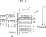
- the electronically controlled mechanical timepiece 1B is different from the electronically controlled mechanical timepiece 1 in that it includes a power-generator-cum-speed-governor 70, which is a speed governor that doubles as a power generator driven by the gear train 50, a rectification circuit 75, which rectifies an alternating current generated by the power-generator-cum-speed-governor 70 into a direct current, and a secondary battery 32, which stores an electric current rectified by the rectification circuit 75.
- a power-generator-cum-speed-governor 70 which is a speed governor that doubles as a power generator driven by the gear train 50
- a rectification circuit 75 which rectifies an alternating current generated by the power-generator-cum-speed-governor 70 into a direct current
- a secondary battery 32 which stores an electric current rectified by the rectification circuit 75.
- the power-generator-cum-speed-governor 70 includes a rotor 71, the rotation of which is linked with the rotation of the gear train 50, and a coil 72, which is wound around a stator.
- the coil 72 thereof is coupled not only to the rotation detection circuit 13 and the speed governing control circuit 14 but also to the rectification circuit 75, and, in this respect, there is a difference from the speed governor 60 according to the first embodiment.
- the rectification circuit 75 is a boost rectifier, a full-wave rectifier, a half-wave rectifier, a transistor rectifier, etc. Any circuit can be adopted as long as it boosts and rectifies an alternating output from the power-generator-cum-speed-governor 70 and supplies a boosted rectified current to the secondary battery 32.
- the secondary battery 32 is a rechargeable secondary cell such as a lithium-ion battery, an all-solid-state battery, or the like.
- an oscillation circuit 11B illustrated in FIG. 9 is used as the oscillation circuit 11B of the electronically controlled mechanical timepiece 1B, although the same circuit as that of the first embodiment can be used.
- the oscillation circuit 11B is a circuit configured to oscillate the quartz oscillator 80.
- the oscillation circuit 11B includes the oscillation inverter 111, which is a CMOS circuit, the feedback resistor 112, the gate capacitor 113 coupled to the gate of the oscillation inverter 111, the drain capacitor 114 coupled to the drain of the oscillation inverter 111, an N-channel transistor 115B, which couples the gate of the oscillation circuit 11B to the power supply terminal VSS, which is a ground, and an inverter 117.
- the oscillation inverter 111 is coupled to power supply terminals VDD and VSS of a power supply circuit coupled to the secondary battery 32.
- the N-channel transistor 115B is configured such that a signal outputted from the rotation detection circuit 13 is inputted to its gate via the inverter 117.
- a High signal is outputted from the rotation detection circuit 13 in the same manner as done in the first embodiment, and a Low signal is inputted to the gate of the N-channel transistor 115B via the inverter 117 to turn off the N-channel transistor 115B.
- the oscillation circuit 11B is put into a usual oscillation state at this time.
- a Low signal is outputted from the rotation detection circuit 13 in the same manner as done in the first embodiment, and a High signal is inputted to the gate of the N-channel transistor 115B via the inverter 117 to turn on the N-channel transistor 115B and pull down the gate of the oscillation inverter 111.
- the oscillation circuit 11B is put into an oscillation stop state at this time because its gate potential is fixed to VSS, which is at a constant level. Since the gate potential of the oscillation circuit 11B is fixed, its output potential is also fixed and it is thus possible to prevent a short-circuiting current from flowing to the frequency division circuit 12 due to an input that is in an indefinite state.
- the speed governing control processing performed for the gear train 50 by a control IC 10B of the electronically controlled mechanical timepiece 1B is the same as that of the electronically controlled mechanical timepiece 1 according to the first embodiment. Therefore, it is not explained here.
- the electronically controlled mechanical timepiece 1B can produce the same operational effects as those of the first embodiment. That is, in the electronically controlled mechanical timepiece 1B, since the control IC 10B is driven using the secondary battery 32, it is possible to make the duration time in which the hands 4 can tell the correct time longer, similarly to the first embodiment. That is, as illustrated in FIG. 10 , since the voltage V0 of a power storage device according to related art drops in conjunction with a decrease in the output torque of the mainspring 40, the time till the time point T1, at which the voltage V0 drops to the drive stop voltage of the control IC 10B or lower, is the duration time T01 according to related art.
- the control IC 10B since the control IC 10B is driven using the secondary battery 32, it is possible to keep the voltage V2 to be greater than or equal to the drive stop voltage of the control IC 10B. For this reason, the time till the time point T2, at which the hands 4 become no longer able to tell the correct time due to running behind because of the decrease in the torque of the mainspring 40, is the duration time T02 of the electronically controlled mechanical timepiece 1B.
- the control IC 10B is configured to be driven using the secondary battery 32, even during a time domain in which the torque of the mainspring 40 has decreased, it is possible to drive the control IC 10B and thus to tell the correct time and lengthen the duration time, similarly to the first embodiment.
- the torque of the mainspring 40 is high and there is an available margin of power generation capability of the power-generator-cum-speed-governor 70, it is possible to store an electric energy into the secondary battery 32 via the rectification circuit 75; therefore, as illustrated in FIG. 10 , it is possible to lengthen the time until the secondary battery 32 runs out. Since it is possible to store an electric energy into the secondary battery 32 each time the mainspring 40 is wound, it is possible to offer longer use even if the secondary battery 32 is configured to have a smaller size and a smaller battery capacity than the battery 31.
- the control IC 10B causes the oscillation circuit 11B to stop so as to decrease current consumption. Therefore, electric discharge from the secondary battery 32 is suppressed, and it is possible to lengthen the time until the battery runs out.
- the electronically controlled mechanical timepiece 1B includes the power-generator-cum-speed-governor 70, the rectification circuit 75, and the secondary battery 32, unlike a case where a primary battery is used, there is no need for battery replacement, and the electronically controlled mechanical timepiece 1B can be used for a long period of time.
- an electronically controlled mechanical timepiece 1C according to a third embodiment will now be described.
- the same reference signs are assigned to the same components as those of the electronically controlled mechanical timepiece 1 according to the first embodiment, and an explanation of the same components will not be repeated.
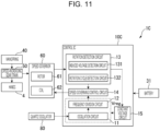
- a control IC 10C of the electronically controlled mechanical timepiece 1C includes a constant voltage circuit 15 configured to drive the oscillation circuit 11 and the frequency division circuit 12.
- the constant voltage circuit 15 is operated or stopped in accordance with a signal coming from the rotation detection circuit 13. Differences from the electronically controlled mechanical timepiece 1 lie in these points.
- the constant voltage circuit 15 is a circuit configured to convert the voltage of the battery 31 into a certain regulated level of voltage (constant voltage) and supply it.
- an output voltage of the constant voltage circuit 15 is a certain regulated level of voltage Vreg without being influenced by the battery voltage.
- the set value of the output of the constant voltage circuit 15 is a discretionary design matter. Setting this value to be greater than a stop voltage of each circuit driven by the output of the constant voltage circuit 15, such as the oscillation circuit 11 and the frequency division circuit 12, will work.
- the control IC 10C When the rotation of the gear train 50 is detected by the rotation detection circuit 13, the control IC 10C operates the constant voltage circuit 15. Therefore, the oscillation circuit 11 and the frequency division circuit 12 also operate, and speed governing control by the speed governing control circuit 14 can also be performed.
- the control IC 10C stops the constant voltage circuit 15.
- the oscillation circuit 11 and the frequency division circuit 12 that were operating by being driven by the output of the constant voltage circuit 15 also stop, making it possible to reduce current consumption. That is, the stopping of the constant voltage circuit 15 stops the oscillation circuit 11, the frequency division circuit 12, and the speed governing control circuit 14 that was being driven by a signal coming from the frequency division circuit 12, thereby stopping the control on the speed governor 60.
- the electronically controlled mechanical timepiece 1C according to the third embodiment can produce the same operational effects as those of the first or second embodiment. Moreover, since the electronically controlled mechanical timepiece 1C includes the constant voltage circuit 15, it is possible to keep the characteristics of the control IC 10C constant without being influenced by the battery voltage and to achieve a further reduction in current consumption.
- the electronically controlled mechanical timepiece 1, 1B, 1C rotates the rotor 61 of the speed governor 60 or the rotor 71 of the power-generator-cum-speed-governor 70 by using the mechanical energy generated from the mainspring 40 and controls the moving speed of each of the hands 4 by performing speed governing control of the rotation speed of the rotor 61, 71.
- this does not imply any limitation.
- the following electronically controlled mechanical timepiece may be adopted: when the gear train 50 configured to transmit the mechanical energy generated from the mainspring 40 is speed-governed using an escape wheel, an anchor, and a balance with hairspring, the electronically controlled mechanical timepiece may detect the vibrations of the balance with hairspring and speed-govern the operation of the balance with hairspring.
- a start of rotation of the gear train 50 is detected by the induced voltage detection circuit 131, and a stop of rotation of the gear train 50 is detected by the rotation cycle detection circuit 132.
- the induced voltage detection circuit 131 may detect both the start of rotation of the gear train 50 and the stop of rotation thereof.
- the method for stopping the speed governing control circuit 14, which is an example of the speed governing controller, is not limited to stopping the oscillation circuit 11.
- the speed governing control circuit 14 may be stopped by shutting off a signal input to the speed governing control circuit 14. As described here, if the oscillation circuit 11 is operating even while the speed governing control circuit 14 is stopped, the rotation cycle detection circuit 132 may detect both the start of rotation of the gear train 50 and the stop of rotation thereof.
- the rotation cycle detection circuit 132 may determine that the rotation has stopped when the detected rotation cycle becomes longer than the set rotation determination time even just once or when the detected rotation cycle is longer than the set rotation determination time consecutively more than once. Similarly, as the condition for determining the start of rotation of the gear train 50, the rotation cycle detection circuit 132 may determine that the rotation has started at the point in time at which the detected rotation cycle becomes shorter than the set rotation determination time or when the detected rotation cycle is shorter than the set rotation determination time consecutively more than once.
- the induced voltage detection circuit 131 may determine that the rotation has started at the point in time at which the detected induced voltage becomes greater than the set rotation determination voltage or when the detected induced voltage is greater than the set rotation determination voltage a predetermined number of times or more within a set time.
- the induced voltage detection circuit 131 may determine that the rotation has stopped at the point in time at which the detected induced voltage becomes less than or equal to the set rotation determination voltage or when the detected induced voltage is less than or equal to the set rotation determination voltage a predetermined number of times or more within a set time. If, especially, determination processing is performed more than once to determine the start of rotation or the stop thereof, it is possible to perform more accurate determination while eliminating a temporary influence by a disturbance.
- a power generator configured to generate power in conjunction with the rotation of the gear train 50 and a speed governor configured to speed-govern the rotation of the gear train 50 may be provided separately from each other.
- the power generator provided separately from the speed governor is not limited to a power generator configured to generate power in conjunction with the rotation of the gear train 50.
- An electrostatic power generator using a solar panel or an electret element, a piezoelectric power generator using a piezoelectric element, a thermal power generator, or the like may be used.
- the oscillation circuit used in the electronically controlled mechanical timepiece 1, 1B, 1C according to each of the foregoing embodiments may be the oscillation circuit 11 according to the first embodiment, the oscillation circuit 11B according to the second embodiment, or an oscillation circuit different from them.
- An electronically controlled mechanical timepiece disclosed herein includes: a mainspring; a gear train adapted to transmit a mechanical energy of the mainspring; a hand driven by the gear train and adapted to tell time; a speed governor adapted to control a rotation cycle of the gear train; a control IC; and a battery adapted to supply power to the control IC.
- the control IC includes: a rotation detector adapted to output a rotation determination signal that is in accordance with rotation of the gear train; and a speed governing controller adapted to control the speed governor.
- the control IC causes the speed governing controller to operate.
- the control IC continues operation of the rotation detector and causes the speed governing controller to stop.
- the control IC since the control IC is driven using power supplied from the battery, it is possible to drive the control IC stably and make the duration time longer.
- the control IC since the control IC includes a rotation detector adapted to output a rotation determination signal that is in accordance with rotation of the gear train and a speed governing controller adapted to control the speed governor, and since the speed governing controller is stopped when the rotation determination signal indicating that the gear train is not rotating is outputted from the rotation detector, it is possible to reduce the power consumption of the control IC, reduce the power supplied from the battery, and make the time till the exhaustion of the battery longer. Furthermore, since the speed governing controller is stopped when the gear train is not rotating due to a decrease in the torque of the mainspring, there is no need to provide a switch between the control IC and the battery, and it is possible to make the size of a movement smaller.
- the rotation detector may be adapted to: detect the rotation cycle of the gear train; when the rotation cycle of the gear train is shorter than a rotation determination time, output the rotation determination signal indicating that the gear train is rotating; and when the rotation cycle of the gear train is longer than or equal to the rotation determination time, output the rotation determination signal indicating that the gear train is not rotating.
- the rotation of the gear train is determined by comparing the rotation cycle of the gear train with the rotation determination time, even when there occurs a period in which a load increases temporarily due to a disturbance or the like and the rotation cycle thus becomes long, it is determined that the gear train is rotating as long as this cycle is shorter than the rotation determination time, thereby avoiding repetitions of the stopping and starting of control by the control IC. Therefore, by setting the rotation determination time suited for the type of the electronically controlled mechanical timepiece, it is possible to detect whether the gear train is rotating or not with high precision, prevent wasteful power consumption without a failure by not operating the speed governing controller when the gear train is not rotating, and suppress electric discharge from the battery for a longer battery life.
- the speed governor may include a coil adapted to generate an induced voltage when the gear train rotates
- the rotation detector may be adapted to: detect the induced voltage; when the induced voltage is greater than the rotation determination voltage, output the rotation determination signal indicating that the gear train is rotating; and when the induced voltage is less than or equal to the rotation determination voltage, output the rotation determination signal indicating that the gear train is not rotating.
- the electronically controlled mechanical timepiece since it is determined that the gear train is not rotating if the induced voltage generated by the coil when the gear train rotates is less than or equal to the rotation determination voltage, and since it is determined that the gear train is rotating if the induced voltage generated by the coil when the gear train rotates is greater than the rotation determination voltage, it is possible to detect the rotation or non-rotation of the gear train just by monitoring the induced voltage and determine whether or not to stop the control on the speed governor easily with low power.
- the speed governor may include a coil adapted to generate an induced voltage when the gear train rotates
- the rotation detector may include: a rotation start detector adapted to detect a start of the rotation of the gear train; and a rotation stop detector adapted to detect a stop of the rotation of the gear train
- the rotation start detector may be adapted to: detect the induced voltage; when the induced voltage is greater than the rotation determination voltage, determine that the gear train has started rotating and output the rotation determination signal indicating that the gear train is rotating; and when the induced voltage is less than or equal to the rotation determination voltage, determine that the gear train is not rotating and output the rotation determination signal indicating that the gear train is not rotating
- the rotation stop detector may be adapted to: detect the rotation cycle of the gear train; when the rotation cycle of the gear train is shorter than a rotation determination time, determine that the gear train is rotating and output the rotation determination signal indicating that the gear train is rotating; and when the rotation cycle of the gear train is longer than or equal to the rotation determination time, determine that the
- the rotation start detector adapted to detect a start of the rotation of the gear train detects the start of the rotation of the gear train by comparing an induced voltage generated by the coil with the rotation determination voltage, it is possible to detect the rotation or non-rotation of the gear train just by monitoring the induced voltage and determine the start of the rotation of the gear train easily with low power even while an oscillation circuit and a frequency division circuit are stopped.
- the rotation stop detector adapted to detect a stop of the rotation of the gear train detects the stop of the rotation of the gear train by comparing the rotation cycle of the gear train with the rotation determination time, it is possible to detect the stop of rotation of the gear train with high precision without being affected by a temporary disturbance.
- control IC may include an oscillation circuit adapted to generate a signal inputted into the speed governing controller, and the speed governing controller may be stopped by stopping the oscillation circuit.
- the oscillation circuit may be a CMOS circuit, and when the oscillation circuit is stopped, power supply to the oscillation circuit may be stopped, and an output signal from the oscillation circuit may be fixed at a constant potential.
- the oscillation circuit may be a CMOS circuit, and when the oscillation circuit is stopped, a gate terminal of the CMOS circuit may be fixed at a constant potential.
- the gate terminal of the oscillation circuit configured as a CMOS circuit is fixed at a constant potential to stop oscillation, it is possible to fix an output from a drain terminal that is the output of the oscillation circuit; accordingly, it is possible to eliminate variations in the output signal of the oscillation circuit that becomes unstable due to the stopping of the oscillation circuit and prevent a short-circuiting current from flowing to a CMOS circuit provided in the frequency division circuit located downstream of the oscillation circuit.
- control IC may include a constant voltage circuit adapted to output a constant voltage to the oscillation circuit, and when the oscillation circuit is stopped, the constant voltage circuit may be stopped.
- the electronically controlled mechanical timepiece With the electronically controlled mechanical timepiece disclosed herein, it is possible to drive the oscillation circuit by means of a constant voltage outputted from the constant voltage circuit, and it is possible to output the constant voltage from the constant voltage circuit even when the voltage of the battery from which power is supplied to the control IC is high. Driving the oscillation circuit by using the constant voltage makes it possible to prevent an increase in current consumption even when the voltage of the battery is high. Moreover, driving the oscillation circuit by using the constant voltage makes it possible to reduce variations caused by the voltage of the output signal. Therefore, it is possible to achieve low current consumption and high precision in the electronically controlled mechanical timepiece and lengthen the time until the battery runs out.
- the electronically controlled mechanical timepiece disclosed herein may further include a power generator adapted to convert the mechanical energy of the mainspring into an electric energy, wherein the battery may be a secondary battery adapted to store the electric energy generated by the power generator.
- the electronically controlled mechanical timepiece disclosed herein includes the secondary battery and the power generator, when there is an available margin in the mechanical energy of the mainspring, it is possible to convert the mechanical energy of the mainspring into an electric energy and store the electric energy into the secondary battery, thereby making the time till the exhaustion of the secondary battery longer.
Landscapes
- Engineering & Computer Science (AREA)
- Power Engineering (AREA)
- Physics & Mathematics (AREA)
- General Physics & Mathematics (AREA)
- Electromechanical Clocks (AREA)
Abstract
An electronically controlled mechanical timepiece includes: a mainspring; a gear train adapted to transmit a mechanical energy of the mainspring; a hand driven by the gear train and adapted to tell time; a speed governor adapted to control a rotation cycle of the gear train; a control IC; and a battery adapted to supply power to the control IC. The control IC includes: a rotation detector adapted to output a rotation determination signal that is in accordance with rotation of the gear train; and a speed governing controller adapted to control the speed governor. When the rotation determination signal indicating that the gear train is rotating is outputted from the rotation detector, the control IC causes the speed governing controller to operate. When the rotation determination signal indicating that the gear train is not rotating is outputted from the rotation detector, the control IC continues operation of a rotation detection function and causes the speed governing controller to stop.
Description
- Embodiments of the present disclosure generally relate to an electronically controlled mechanical timepiece.
- In the field of an electronically controlled mechanical timepiece configured to rotate hands coupled to a gear train by using a mechanical energy produced when a mainspring is released and configured to control a speed governor coupled to the gear train by means of a rotation controlling unit,
JP-A-11-52077 - In the electronically controlled mechanical timepiece disclosed in
JP-A-11-52077 - However, providing a switch between an IC and a battery results in an increase in size of a movement of a timepiece. Therefore, an electronically controlled mechanical timepiece that includes a battery configured to supply an electric energy to an IC, and makes it possible to prevent wasteful power consumption and suppress an increase in size of a movement is demanded.
- An electronically controlled mechanical timepiece according to a certain aspect of the present disclosure includes: a mainspring; a gear train adapted to transmit a mechanical energy of the mainspring; a hand driven by the gear train and adapted to tell time; a speed governor adapted to control a rotation cycle of the gear train; a control IC; and a battery adapted to supply power to the control IC. The control IC includes: a rotation detector adapted to output a rotation determination signal that is in accordance with rotation of the gear train; and a speed governing controller adapted to control the speed governor. When the rotation determination signal indicating that the gear train is rotating is outputted from the rotation detector, the control IC causes the speed governing controller to operate. When the rotation determination signal indicating that the gear train is not rotating is outputted from the rotation detector, the control IC continues operation of the rotation detector and causes the speed governing controller to stop.
-
-
FIG. 1 is a front view of an electronically controlled mechanical timepiece according to a first embodiment. -
FIG. 2 is a block diagram that illustrates a schematic configuration of the electronically controlled mechanical timepiece according to the first embodiment. -
FIG. 3 is a circuit diagram that illustrates an oscillation circuit according to the first embodiment. -
FIG. 4 is a flowchart that illustrates speed governing control processing according to the first embodiment. -
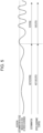
FIG. 5 is a diagram for explaining rotation detection processing performed by an induced voltage detection circuit according to the first embodiment. -
FIG. 6 is a diagram for explaining rotation detection processing performed by a rotation cycle detection circuit according to the first embodiment. -
FIG. 7 is a graph that illustrates a relationship among a power storage device voltage, an IC consumption current, and a mainspring output torque according to the first embodiment. -
FIG. 8 is a block diagram that illustrates a schematic configuration of an electronically controlled mechanical timepiece according to a second embodiment. -
FIG. 9 is a circuit diagram that illustrates an oscillation circuit according to the second embodiment. -
FIG. 10 is a graph that illustrates a relationship among a power storage device voltage, an IC consumption current, and a mainspring output torque according to the second embodiment. -
FIG. 11 is a block diagram that illustrates a schematic configuration of an electronically controlled mechanical timepiece according to a third embodiment. - With reference to the accompanying drawings, an electronically controlled
mechanical timepiece 1 according to an embodiment of the present disclosure will now be described. -
FIG. 1 is a front view of the electronically controlledmechanical timepiece 1. As illustrated inFIG. 1 , the electronically controlledmechanical timepiece 1 is a wristwatch worn on the wrist of a user, and includes acase 2 having a cylindrical low-profile shape. Adial 3 is disposed inside thecase 2. The front one of two openings of thecase 2 is closed by a cover glass, and the back one of them is closed by a case back. - The electronically controlled
mechanical timepiece 1 includes a non-illustrated movement, which is housed in thecase 2, andhands 4, which tell time. Thehands 4 are made up of anhour hand 4A, aminute hand 4B, and asecond hand 4C. Thedial 3 has acalendar window 3A. Acalendar disc 6 can be seen through thecalendar window 3A. Thedial 3 further hashour marks 3B for reading the time and a fan-shaped sub dial 3C for letting the user know a duration time by means of apower reserve indicator 5. - A
crown 7 is provided on a side of thecase 2. Thecrown 7 can be moved by being pulled out to a first-click position and to a second-click position from a zeroth-click position of being pushed in toward the center of the electronically controlledmechanical timepiece 1. - By pulling the
crown 7 out to the first-click position and then rotating thecrown 7, the user can move thecalendar disc 6 to set the date. When the user pulls thecrown 7 out to the second-click position, thesecond hand 4C stops. Then, when the user rotates thecrown 7 at the second-click position, thehour hand 4A and theminute hand 4B move. By this means, the user can set the time. The methods as to how to correct the position of thecalendar disc 6 and how to correct the positions of thehour hand 4A and theminute hand 4B by winding thecrown 7 are the same as those of timepieces according to related art; therefore, an explanation thereof is omitted. - By rotating the
crown 7 at the zeroth-click position, the user can wind up amainspring 40 to be described later. Linked with the winding of themainspring 40, thepower reserve indicator 5 moves. -
FIG. 2 is a block diagram that illustrates a schematic configuration of the electronically controlledmechanical timepiece 1. - As illustrated in
FIG. 2 , the electronically controlledmechanical timepiece 1 includes a control integrated circuit (IC) 10, which is an example of a controller, amainspring 40, which is an example of a mechanical energy source, agear train 50, which is an example of an energy transmission device configured to transmit a torque of themainspring 40,hands 4, which is coupled to thegear train 50 and tells time, aspeed governor 60, which controls a rotation cycle of thegear train 50, aquartz oscillator 80, and abattery 31. - The
control IC 10 includes anoscillation circuit 11, afrequency division circuit 12, arotation detection circuit 13, and a speed governingcontrol circuit 14. Therotation detection circuit 13 is an example of a rotation detector configured to detect the rotation of thegear train 50. Therotation detection circuit 13 includes an inducedvoltage detection circuit 131 and a rotationcycle detection circuit 132. The speed governingcontrol circuit 14 is an example of a speed governing controller configured to control thespeed governor 60. - The
mainspring 40 is wound up by means of thecrown 7 via a winding-up gear train that is not illustrated. - The
gear train 50 is comprised of a plurality of gears configured to be rotated by a mechanical energy stored in themainspring 40. Thegear train 50 operates thehour hand 4A, theminute hand 4B, and thesecond hand 4C, which are mounted on the shaft of these gears. Thegear train 50 is a speed-increasing gear train configured to transmit the rotation of a barrel by themainspring 40 with an increase in speed, similarly to that of an ordinary mechanical timepiece. - The speed governor 60 includes a
rotor 61, in which a magnet is built, and acoil 62, which is wound around a stator. Therotor 61 is coupled to thegear train 50 because a pinion formed integrally therewith is in mesh with thegear train 50. Linked with the rotation of thegear train 50, therotor 61 rotates. Therefore, by measuring the cycle of therotor 61 of thespeed governor 60, it is possible to determine whether thegear train 50 is moving or not. Moreover, by controlling the time of applying a short-circuit brake to therotor 61 by short-circuiting thecoil 62 and thereby adjusting the rotation speed of therotor 61, it is possible to govern the speed of thegear train 50. - Though not illustrated, a winding-up gear train configured to wind up the
mainspring 40 and a power reserve gear train interlocked with thegear train 50 are provided. Thepower reserve indicator 5 is mounted on the power reserve gear train. - The
battery 31 is a replaceable button-type primary battery or the like for use in a wristwatch. Thebattery 31 supplies power to thecontrol IC 10. - Next, with reference to
FIG. 3 , the configuration of theoscillation circuit 11 will now be described. - The
oscillation circuit 11 is a circuit configured to oscillate thequartz oscillator 80. Theoscillation circuit 11 includes anoscillation inverter 111 that is a CMOS (Complementary Metal Oxide Semiconductor) circuit, afeedback resistor 112, agate capacitor 113 coupled to the gate of theoscillation inverter 111, adrain capacitor 114 coupled to the drain of theoscillation inverter 111, an N-channel transistor 115, and an ANDgate 116. - The
oscillation inverter 111 is coupled to power supply terminals VDD and VSS of a power supply circuit coupled to thebattery 31. Theoscillation inverter 111 is coupled to the power supply terminal VSS via the N-channel transistor 115. - A signal outputted from the
rotation detection circuit 13 is inputted to the gate of the N-channel transistor 115. By this means, the N-channel transistor 115 behaves as an ON/OFF switch for connection/disconnection between theoscillation inverter 111 and the power supply terminal VSS. - As illustrated in
FIG. 2 , therotation detection circuit 13 includes the inducedvoltage detection circuit 131 and the rotationcycle detection circuit 132. The inducedvoltage detection circuit 131 is a circuit configured to detect an induced voltage generated at thecoil 62 of thespeed governor 60 and configured to determine whether or not the detected induced voltage is less than or equal to a rotation determination voltage that has been set in advance. The inducedvoltage detection circuit 131 compares the detected induced voltage with the rotation determination voltage. When the detected induced voltage is greater than the rotation determination voltage, the inducedvoltage detection circuit 131 determines that thegear train 50 is rotating. In this case, the inducedvoltage detection circuit 131 outputs a High signal to the gate of the N-channel transistor 115. When the detected induced voltage is less than or equal to the rotation determination voltage, the inducedvoltage detection circuit 131 determines that thegear train 50 is not rotating. In this case, the inducedvoltage detection circuit 131 outputs a Low signal to the gate of the N-channel transistor 115. - The rotation
cycle detection circuit 132 includes a non-illustrated waveform shaping circuit and a non-illustrated mono multivibrator that are coupled to thespeed governor 60. The rotationcycle detection circuit 132 shapes the waveform of the induced voltage detected by the inducedvoltage detection circuit 131, and outputs a rotation detection signal FG1, which indicates the rotation frequency (rotation cycle) of therotor 61 of thespeed governor 60, to the speedgoverning control circuit 14. When the measured rotation cycle is shorter than or equal to a rotation determination time, the rotationcycle detection circuit 132 determines that thegear train 50 is rotating. In this case, the rotationcycle detection circuit 132 outputs a High signal to the gate of the N-channel transistor 115. When the measured rotation cycle is longer than the rotation determination time, the rotationcycle detection circuit 132 determines that thegear train 50 is not rotating. In this case, the rotationcycle detection circuit 132 outputs a Low signal to the gate of the N-channel transistor 115. - The High signal outputted from the induced
voltage detection circuit 131 and the rotationcycle detection circuit 132 is an example of a rotation determination signal indicating that thegear train 50 is rotating. The Low signal outputted from the inducedvoltage detection circuit 131 and the rotationcycle detection circuit 132 is an example of a rotation determination signal indicating that thegear train 50 is not rotating. - The N-
channel transistor 115 switches on when a High signal is inputted to its gate. As a result of this switching on, a power path to theoscillation inverter 111 is established, and theoscillation circuit 11 operates. On the other hand, the N-channel transistor 115 switches off when a Low signal is inputted to its gate. As a result of this switching off, the power path to theoscillation inverter 111 is shut off, and the power supply stops. Therefore, theoscillation circuit 11 stops operating. - An output signal of the
oscillation inverter 111 and a signal coming from therotation detection circuit 13 are inputted into the ANDgate 116. An output signal of the ANDgate 116 is inputted into thefrequency division circuit 12. - While a Low signal is outputted from the
rotation detection circuit 13, the output of theoscillation inverter 111 is indefinite; however, since the Low signal coming from therotation detection circuit 13 is inputted into the ANDgate 116, to which the output terminal of theoscillation inverter 111 is coupled, the output of the ANDgate 116 is fixed at a constant potential of Low, and it is thus possible to prevent a short-circuiting current from flowing to thefrequency division circuit 12 due to an input that is in an indefinite state. - The
oscillation circuit 11 causes thequartz oscillator 80, which is an oscillation signal generation source, to oscillate. An oscillation signal (32768 Hz) of thequartz oscillator 80 is outputted to thefrequency division circuit 12. - The
frequency division circuit 12 frequency-divides the oscillation signal to perform clock signal generation of a plurality of frequencies (for example, 2 kHz to 8 Hz), and outputs a required clock signal to the speedgoverning control circuit 14. The clock signal outputted from thefrequency division circuit 12 to the speedgoverning control circuit 14 is a reference signal fs1 taken as a reference for rotation control of therotor 61 of thespeed governor 60 as will be described later. - The speed
governing control circuit 14, which is an example of a speed governing controller configured to control thespeed governor 60, compares the rotation detection signal FG1 outputted from the rotationcycle detection circuit 132 of therotation detection circuit 13 with the reference signal fs1 outputted from thefrequency division circuit 12, and outputs, to thespeed governor 60, a braking control signal for performing speed governing control on thespeed governor 60. - The reference signal fs1 is a signal coordinated to a reference rotation speed (for example, 8 Hz) of the
rotor 61 during usual hand-moving operation. Therefore, in accordance with the difference between the rotation speed of the rotor 61 (the rotation detection signal FG1) and the reference signal fs1, the speedgoverning control circuit 14 changes the duty ratio of the braking control signal, controls the ON time of a chopping transistor for braking use coupled to thecoil 62 of thespeed governor 60 to adjust a short-circuit braking force, and thereby controls the cycle of therotor 61. Since therotor 61 of thespeed governor 60 is in mesh with thegear train 50, by controlling the cycle of therotor 61, it is possible to adjust the cycle of thegear train 50, that is, the moving speed of thehands 4. - Next, with reference to
FIGs. 4 to 7 , speed governing control processing performed for thegear train 50 by thecontrol IC 10 will now be described.FIG. 4 is a flowchart for explaining the speed governing control processing performed by thecontrol IC 10. This flowchart illustrates a case where the speed governing control processing is started from a state in which thegear train 50 is stopped. - The
control IC 10 starts the speed governing control in a state in which the rotation of thegear train 50 is stopped due to releasing of the mainspring 40 (step S1). In this control stop state of step S1, thecontrol IC 10 outputs a Low signal from therotation detection circuit 13 to stop theoscillation circuit 11; therefore, thefrequency division circuit 12 and the speedgoverning control circuit 14 are also in a stopped state. That is, thecontrol IC 10 stops the speedgoverning control circuit 14, which is an example of the speed governing controller, by stopping theoscillation circuit 11. - In addition, in the control stop state of step S1, since the
control IC 10 stops theoscillation circuit 11, no clock signal that is needed for rotation cycle detection is outputted from thefrequency division circuit 12; therefore, the rotationcycle detection circuit 132 is in a stopped state. On the other hand, since a clock signal is not needed for detecting an induced voltage generated at thecoil 62, thecontrol IC 10 renders the inducedvoltage detection circuit 131 of therotation detection circuit 13 operating. - Next, the
control IC 10 compares the induced voltage detected by the inducedvoltage detection circuit 131 with the rotation determination voltage to determine whether or not rotation has been detected by means of the induced voltage (step S2). As illustrated inFIG. 5 , when the induced voltage generated at thecoil 62 of thespeed governor 60 is less than or equal to the rotation determination voltage, thecontrol IC 10 determines that therotor 61 of thespeed governor 60, that is, thegear train 50, is not rotating, determines as "not detected" in step S2, and keeps the control stop state of step S1. - On the other hand, as illustrated in
FIG. 5 , at a point in time at which the induced voltage generated at thecoil 62 of thespeed governor 60 becomes greater than the rotation determination voltage, thecontrol IC 10 determines that therotor 61 of thespeed governor 60, that is, thegear train 50, is rotating, determines as "detected" in step S2, and starts the speed governing control (step S3). - Just by monitoring the induced voltage generated at the
coil 62, the inducedvoltage detection circuit 131 can detect whether or not thegear train 50 starts rotating; therefore, it is possible to determine the start of control on thespeed governor 60 easily with low power. Therefore, the inducedvoltage detection circuit 131 behaves as an example of a rotation start detector configured to detect a start of rotation of thegear train 50. - When it is determined in step S2 that the rotation is detected, the
control IC 10 starts speed governing control on thegear train 50 and the speed governor 60 (step S3). That is, upon starting the speed governing control in step S3, thecontrol IC 10 outputs a High signal from therotation detection circuit 13 to theoscillation circuit 11, activates theoscillation circuit 11, and further activates the rotationcycle detection circuit 132. When the speed governing control in step S3 is started, the inducedvoltage detection circuit 131 stops its function as the rotation start detector, that is, its function of comparing the detected induced voltage with the rotation determination voltage and outputting the rotation determination signal. The inducedvoltage detection circuit 131 continues its function of detecting the induced voltage generated at thecoil 62 of thespeed governor 60. In step S3 and the subsequent steps, the rotation determination signal is outputted from the rotationcycle detection circuit 132. - The
control IC 10 is in a speed governing control state after the start of the speed governing control in step S3 (step S4). In this speed governing control state, as illustrated inFIG. 6 , the rotationcycle detection circuit 132 shapes the waveform of the induced voltage of thespeed governor 60 detected by the inducedvoltage detection circuit 131, outputs the waveform-shaped voltage as the rotation detection signal FG1 to the speedgoverning control circuit 14, and detects the cycle of this waveform. - The speed
governing control circuit 14 compares the rotation detection signal FG1 outputted from the rotationcycle detection circuit 132 with the reference signal fs1 outputted by frequency-dividing the oscillation signal outputted from theoscillation circuit 11 at thefrequency division circuit 12, and performs braking control on thespeed governor 60 on the basis of the comparison result. - Based on the rotation cycle detected by the rotation
cycle detection circuit 132, thecontrol IC 10 determines whether or not thegear train 50 is rotating (step S5). Specifically, when the rotation cycle detected by the rotationcycle detection circuit 132 is shorter than a rotation determination time T_nodet, it is determined that thegear train 50 is rotating. When the rotation cycle detected by the rotationcycle detection circuit 132 is longer than or equal to the rotation determination time T_nodet, it is determined that thegear train 50 is not rotating. For example, in the example illustrated inFIG. 6 , from rotation cycles t1 to t4, each rotation cycle is shorter than the rotation determination time T_nodet; therefore, thecontrol IC 10 determines that thegear train 50 is rotating. Though the length of T4 is greater than the length of each of T1 to T3, in the electronically controlledmechanical timepiece 1, it could happen that the rotation cycle becomes long temporarily due to the influence of timepiece orientation or the like, and, with this taken into consideration, the rotation determination time T_nodet is preset to be longer to some extent than the reference cycle of therotor 61 of thespeed governor 60; therefore, the determination result is "rotating" for the case of T4, too. For example, when the reference cycle of therotor 61 of thespeed governor 60 is a one-eighth of a second (= 8 Hz), the rotation determination time T_nodet is preset to be a quarter of a second (= 4 Hz). This makes it possible to eliminate the execution of an unnecessary control stop when the rotation cycle becomes long temporarily. - Since each of t5 and t6 is longer than the rotation determination time T_nodet, the
control IC 10 determines that thegear train 50 is not rotating. At a point in time at which the rotation cycle t5 is detected, thecontrol IC 10 determines that thegear train 50 is not rotating because t5 is longer than the rotation determination time T_nodet. Therefore, the inducedvoltage detection circuit 131 and the rotationcycle detection circuit 132 behave as an example of a rotation stop detector configured to detect a stop of rotation of thegear train 50. - When it is determined in step S5 that the rotation is detected, the
control IC 10 continues the speed governing control in step S4. - When it is determined in step S5 that the rotation is not detected, the
control IC 10 returns the process to the control stop state of step S1. In the control stop state, therotation detection circuit 13 outputs a Low signal to theoscillation circuit 11 and stops theoscillation circuit 11 by turning off the N-channel transistor 115. By this means, it is possible to reduce power consumption. In addition, thecontrol IC 10 starts the function of the inducedvoltage detection circuit 131 as the rotation start detector and stops the rotationcycle detection circuit 132. - The case where the determination result in step S5 is "not rotating" is a case where the output torque of the
mainspring 40 has decreased. In this case, the control stop state of step S1 continues until themainspring 40 is wound up again. When an induced voltage is generated at thecoil 62 due to the winding of the mainspring 40 by the user of the electronically controlledmechanical timepiece 1, it is determined in step S2 that rotation is detected, and the processing in steps S3 to S5 is executed. - According to the electronically controlled
mechanical timepiece 1, when the rotation cycle becomes long due to uncoiling of the mainspring 40, thecontrol IC 10 stops theoscillation circuit 11; therefore, it is possible to keep current consumption low. As compared with use without stopping theoscillation circuit 11, for this reason, it is possible to lengthen the time until thebattery 31 runs out and thus to continue using the electronically controlledmechanical timepiece 1 for a long period of time. For example, when the capacity of thebattery 31 is 5 mAH and the current consumption of thecontrol IC 10 while theoscillation circuit 11 is operating is 40 nA, it takes approximately 14 years for thebattery 31 to run out if operation continues without stopping theoscillation circuit 11. On the other hand, the current consumption while theoscillation circuit 11 is stopped is, for example, 10 nA, which is approximately a quarter of the current consumption while theoscillation circuit 11 is operating. Therefore, the current consumption decreases significantly if theoscillation circuit 11 is stopped during a period in which thegear train 50 is stopped because themainspring 40 is in a released state. Accordingly, it is possible to further lengthen the time until thebattery 31 runs out and thus to continue using the electronically controlledmechanical timepiece 1 for a long period of time. - Moreover, since the
battery 31 is used as the power source of thecontrol IC 10, it is possible to make the duration time in which thehands 4 can tell the correct time longer, as compared with a case where power is generated by a power generator that doubles as a speed governor driven by a mainspring and where thecontrol IC 10 is driven using power stored in a capacitor, as done in an electronically controlled mechanical timepiece of related art. That is, as illustrated inFIG. 7 , let V0 be a voltage of a power storage device of related art that is a capacitor charged by a power generator driven by a mainspring, and let V1 be a voltage of thebattery 31 that is a power storage device according to the present embodiment, and, given this definition, the voltage V0 drops in conjunction with a decrease in the output torque of themainspring 40. For this reason, when the voltage V0 drops to a drive stop voltage of thecontrol IC 10 or lower, thecontrol IC 10 stops, making it impossible to perform speed governing control on thespeed governor 60 and thus making it impossible for thehands 4 to tell the correct time. In this case, the time till a time point T1, at which the voltage V0 drops to the drive stop voltage of thecontrol IC 10 or lower, is the duration time T01 of this timepiece. - On the other hand, in the present embodiment, since the
control IC 10 is driven using thebattery 31 that is a power storage device, even with a decrease in the torque of the mainspring 40, it is possible to keep the voltage V1 of thebattery 31 to be greater than or equal to the drive stop voltage of thecontrol IC 10. For this reason, the time till a time point T2, at which thehands 4 become no longer able to tell the correct time due to running behind because of the decrease in the torque of the mainspring 40, is the duration time T02 of the electronically controlledmechanical timepiece 1. In the present embodiment, since thecontrol IC 10 is configured to be driven using thebattery 31, even during a period from the time point T1 to the time point T2 where the torque of themainspring 40 has decreased, it is possible to drive thecontrol IC 10 by using thebattery 31 and thus to tell the correct time and offer the duration time T02 that is longer. For example, if the duration time T01 according to related art is approximately 72 hours, the duration time T02 according to the present embodiment is approximately 90 hours. - Furthermore, at a time point T3, at which the
mainspring 40 becomes uncoiled all the way and thegear train 50 therefore stops, thecontrol IC 10 causes theoscillation circuit 11 to stop so as to decrease current consumption. This suppresses electric discharge from thebattery 31 and makes it possible to lengthen the time until thebattery 31 runs out. - Note that, in the graph showing changes in the voltages V0 and V1 of the power storage devices in
FIG. 7 , the voltage changes are illustrated in an exaggerated manner for easier understanding. The same holds true forFIG. 10 to be described later. - The
control IC 10 stops theoscillation circuit 11 and thus stops the speedgoverning control circuit 14, which is an example of the speed governing controller, when therotation detection circuit 13 detects that thegear train 50 is not rotating because the torque of themainspring 40 has decreased. Therefore, it is possible to make the size of the movement smaller without any need for providing a switch between thecontrol IC 10 and thebattery 31. - The
rotation detection circuit 13, when in a control stop state, monitors the induced voltage generated at thecoil 62 by means of the inducedvoltage detection circuit 131. Therefore, even when theoscillation circuit 11 and thefrequency division circuit 12 are stopped, it is possible to detect a start of rotation of thegear train 50 and perform determination regarding the start of rotation of thegear train 50 easily with low power. - The
rotation detection circuit 13, when in a speed governing control state, detects the rotation cycle of therotor 61 by means of the rotationcycle detection circuit 132. Therefore, it is possible to detect a stop of rotation of thegear train 50 with high precision without being affected by a temporary disturbance. - Next, with reference to
FIGs. 8 to 10 , an electronically controlledmechanical timepiece 1B according to a second embodiment will now be described. In the electronically controlledmechanical timepiece 1B, the same reference signs are assigned to the same components as those of the electronically controlledmechanical timepiece 1 according to the first embodiment, and an explanation of the same components will not be repeated. - The electronically controlled
mechanical timepiece 1B is different from the electronically controlledmechanical timepiece 1 in that it includes a power-generator-cum-speed-governor 70, which is a speed governor that doubles as a power generator driven by thegear train 50, arectification circuit 75, which rectifies an alternating current generated by the power-generator-cum-speed-governor 70 into a direct current, and asecondary battery 32, which stores an electric current rectified by therectification circuit 75. - Similarly to the
speed governor 60, the power-generator-cum-speed-governor 70 includes arotor 71, the rotation of which is linked with the rotation of thegear train 50, and acoil 72, which is wound around a stator. However, since the power-generator-cum-speed-governor 70 behaves also as a power generator, thecoil 72 thereof is coupled not only to therotation detection circuit 13 and the speedgoverning control circuit 14 but also to therectification circuit 75, and, in this respect, there is a difference from thespeed governor 60 according to the first embodiment. - The
rectification circuit 75 is a boost rectifier, a full-wave rectifier, a half-wave rectifier, a transistor rectifier, etc. Any circuit can be adopted as long as it boosts and rectifies an alternating output from the power-generator-cum-speed-governor 70 and supplies a boosted rectified current to thesecondary battery 32. - The
secondary battery 32 is a rechargeable secondary cell such as a lithium-ion battery, an all-solid-state battery, or the like. - In the second embodiment, an
oscillation circuit 11B illustrated inFIG. 9 is used as theoscillation circuit 11B of the electronically controlledmechanical timepiece 1B, although the same circuit as that of the first embodiment can be used. - The
oscillation circuit 11B is a circuit configured to oscillate thequartz oscillator 80. Theoscillation circuit 11B includes theoscillation inverter 111, which is a CMOS circuit, thefeedback resistor 112, thegate capacitor 113 coupled to the gate of theoscillation inverter 111, thedrain capacitor 114 coupled to the drain of theoscillation inverter 111, an N-channel transistor 115B, which couples the gate of theoscillation circuit 11B to the power supply terminal VSS, which is a ground, and aninverter 117. - The
oscillation inverter 111 is coupled to power supply terminals VDD and VSS of a power supply circuit coupled to thesecondary battery 32. - The N-
channel transistor 115B is configured such that a signal outputted from therotation detection circuit 13 is inputted to its gate via theinverter 117. - When the rotation of the
gear train 50 is detected by therotation detection circuit 13, a High signal is outputted from therotation detection circuit 13 in the same manner as done in the first embodiment, and a Low signal is inputted to the gate of the N-channel transistor 115B via theinverter 117 to turn off the N-channel transistor 115B. Theoscillation circuit 11B is put into a usual oscillation state at this time. - When the rotation of the
gear train 50 is not detected by therotation detection circuit 13, a Low signal is outputted from therotation detection circuit 13 in the same manner as done in the first embodiment, and a High signal is inputted to the gate of the N-channel transistor 115B via theinverter 117 to turn on the N-channel transistor 115B and pull down the gate of theoscillation inverter 111. Theoscillation circuit 11B is put into an oscillation stop state at this time because its gate potential is fixed to VSS, which is at a constant level. Since the gate potential of theoscillation circuit 11B is fixed, its output potential is also fixed and it is thus possible to prevent a short-circuiting current from flowing to thefrequency division circuit 12 due to an input that is in an indefinite state. - The speed governing control processing performed for the
gear train 50 by acontrol IC 10B of the electronically controlledmechanical timepiece 1B is the same as that of the electronically controlledmechanical timepiece 1 according to the first embodiment. Therefore, it is not explained here. - The electronically controlled
mechanical timepiece 1B can produce the same operational effects as those of the first embodiment. That is, in the electronically controlledmechanical timepiece 1B, since thecontrol IC 10B is driven using thesecondary battery 32, it is possible to make the duration time in which thehands 4 can tell the correct time longer, similarly to the first embodiment. That is, as illustrated inFIG. 10 , since the voltage V0 of a power storage device according to related art drops in conjunction with a decrease in the output torque of the mainspring 40, the time till the time point T1, at which the voltage V0 drops to the drive stop voltage of thecontrol IC 10B or lower, is the duration time T01 according to related art. - On the other hand, in the present embodiment, since the
control IC 10B is driven using thesecondary battery 32, it is possible to keep the voltage V2 to be greater than or equal to the drive stop voltage of thecontrol IC 10B. For this reason, the time till the time point T2, at which thehands 4 become no longer able to tell the correct time due to running behind because of the decrease in the torque of the mainspring 40, is the duration time T02 of the electronically controlledmechanical timepiece 1B. In the present embodiment, since thecontrol IC 10B is configured to be driven using thesecondary battery 32, even during a time domain in which the torque of themainspring 40 has decreased, it is possible to drive thecontrol IC 10B and thus to tell the correct time and lengthen the duration time, similarly to the first embodiment. - Moreover, while the torque of the
mainspring 40 is high and there is an available margin of power generation capability of the power-generator-cum-speed-governor 70, it is possible to store an electric energy into thesecondary battery 32 via therectification circuit 75; therefore, as illustrated inFIG. 10 , it is possible to lengthen the time until thesecondary battery 32 runs out. Since it is possible to store an electric energy into thesecondary battery 32 each time themainspring 40 is wound, it is possible to offer longer use even if thesecondary battery 32 is configured to have a smaller size and a smaller battery capacity than thebattery 31. Furthermore, at the time point T3, at which themainspring 40 becomes uncoiled all the way and thegear train 50 therefore stops, thecontrol IC 10B causes theoscillation circuit 11B to stop so as to decrease current consumption. Therefore, electric discharge from thesecondary battery 32 is suppressed, and it is possible to lengthen the time until the battery runs out. - Since the electronically controlled
mechanical timepiece 1B includes the power-generator-cum-speed-governor 70, therectification circuit 75, and thesecondary battery 32, unlike a case where a primary battery is used, there is no need for battery replacement, and the electronically controlledmechanical timepiece 1B can be used for a long period of time. - Next, with reference to
FIG. 11 , an electronically controlledmechanical timepiece 1C according to a third embodiment will now be described. In the electronically controlledmechanical timepiece 1C, the same reference signs are assigned to the same components as those of the electronically controlledmechanical timepiece 1 according to the first embodiment, and an explanation of the same components will not be repeated. - A
control IC 10C of the electronically controlledmechanical timepiece 1C includes aconstant voltage circuit 15 configured to drive theoscillation circuit 11 and thefrequency division circuit 12. Theconstant voltage circuit 15 is operated or stopped in accordance with a signal coming from therotation detection circuit 13. Differences from the electronically controlledmechanical timepiece 1 lie in these points. - The
constant voltage circuit 15 is a circuit configured to convert the voltage of thebattery 31 into a certain regulated level of voltage (constant voltage) and supply it. When the voltage of thebattery 31 has a set value or greater, an output voltage of theconstant voltage circuit 15 is a certain regulated level of voltage Vreg without being influenced by the battery voltage. The set value of the output of theconstant voltage circuit 15 is a discretionary design matter. Setting this value to be greater than a stop voltage of each circuit driven by the output of theconstant voltage circuit 15, such as theoscillation circuit 11 and thefrequency division circuit 12, will work. - When the rotation of the
gear train 50 is detected by therotation detection circuit 13, thecontrol IC 10C operates theconstant voltage circuit 15. Therefore, theoscillation circuit 11 and thefrequency division circuit 12 also operate, and speed governing control by the speedgoverning control circuit 14 can also be performed. - On the other hand, when the rotation of the
gear train 50 is not detected by therotation detection circuit 13, thecontrol IC 10C stops theconstant voltage circuit 15. As a result, theoscillation circuit 11 and thefrequency division circuit 12 that were operating by being driven by the output of theconstant voltage circuit 15 also stop, making it possible to reduce current consumption. That is, the stopping of theconstant voltage circuit 15 stops theoscillation circuit 11, thefrequency division circuit 12, and the speedgoverning control circuit 14 that was being driven by a signal coming from thefrequency division circuit 12, thereby stopping the control on thespeed governor 60. - The electronically controlled
mechanical timepiece 1C according to the third embodiment can produce the same operational effects as those of the first or second embodiment. Moreover, since the electronically controlledmechanical timepiece 1C includes theconstant voltage circuit 15, it is possible to keep the characteristics of thecontrol IC 10C constant without being influenced by the battery voltage and to achieve a further reduction in current consumption. - The scope of the present disclosure is not limited to the foregoing embodiments. Alterations, improvements, and the like that can be made within a range of attaining the purpose of the present disclosure are encompassed with the scope of the present disclosure.
- The electronically controlled
mechanical timepiece rotor 61 of thespeed governor 60 or therotor 71 of the power-generator-cum-speed-governor 70 by using the mechanical energy generated from themainspring 40 and controls the moving speed of each of thehands 4 by performing speed governing control of the rotation speed of therotor gear train 50 configured to transmit the mechanical energy generated from themainspring 40 is speed-governed using an escape wheel, an anchor, and a balance with hairspring, the electronically controlled mechanical timepiece may detect the vibrations of the balance with hairspring and speed-govern the operation of the balance with hairspring. - In each of the foregoing embodiments, a start of rotation of the
gear train 50 is detected by the inducedvoltage detection circuit 131, and a stop of rotation of thegear train 50 is detected by the rotationcycle detection circuit 132. However, the inducedvoltage detection circuit 131 may detect both the start of rotation of thegear train 50 and the stop of rotation thereof. - The method for stopping the speed
governing control circuit 14, which is an example of the speed governing controller, is not limited to stopping theoscillation circuit 11. The speedgoverning control circuit 14 may be stopped by shutting off a signal input to the speedgoverning control circuit 14. As described here, if theoscillation circuit 11 is operating even while the speedgoverning control circuit 14 is stopped, the rotationcycle detection circuit 132 may detect both the start of rotation of thegear train 50 and the stop of rotation thereof. - As the condition for determining the stop of rotation of the
gear train 50, the rotationcycle detection circuit 132 may determine that the rotation has stopped when the detected rotation cycle becomes longer than the set rotation determination time even just once or when the detected rotation cycle is longer than the set rotation determination time consecutively more than once. Similarly, as the condition for determining the start of rotation of thegear train 50, the rotationcycle detection circuit 132 may determine that the rotation has started at the point in time at which the detected rotation cycle becomes shorter than the set rotation determination time or when the detected rotation cycle is shorter than the set rotation determination time consecutively more than once. - As the condition for determining the start of rotation of the
gear train 50, the inducedvoltage detection circuit 131 may determine that the rotation has started at the point in time at which the detected induced voltage becomes greater than the set rotation determination voltage or when the detected induced voltage is greater than the set rotation determination voltage a predetermined number of times or more within a set time. As the condition for determining the stop of rotation of thegear train 50, the inducedvoltage detection circuit 131 may determine that the rotation has stopped at the point in time at which the detected induced voltage becomes less than or equal to the set rotation determination voltage or when the detected induced voltage is less than or equal to the set rotation determination voltage a predetermined number of times or more within a set time. If, especially, determination processing is performed more than once to determine the start of rotation or the stop thereof, it is possible to perform more accurate determination while eliminating a temporary influence by a disturbance. - Though the power-generator-cum-speed-
governor 70 is provided in the second embodiment, instead, a power generator configured to generate power in conjunction with the rotation of thegear train 50 and a speed governor configured to speed-govern the rotation of thegear train 50 may be provided separately from each other. The power generator provided separately from the speed governor is not limited to a power generator configured to generate power in conjunction with the rotation of thegear train 50. An electrostatic power generator using a solar panel or an electret element, a piezoelectric power generator using a piezoelectric element, a thermal power generator, or the like may be used. - The oscillation circuit used in the electronically controlled
mechanical timepiece oscillation circuit 11 according to the first embodiment, theoscillation circuit 11B according to the second embodiment, or an oscillation circuit different from them. - An electronically controlled mechanical timepiece disclosed herein includes: a mainspring; a gear train adapted to transmit a mechanical energy of the mainspring; a hand driven by the gear train and adapted to tell time; a speed governor adapted to control a rotation cycle of the gear train; a control IC; and a battery adapted to supply power to the control IC. The control IC includes: a rotation detector adapted to output a rotation determination signal that is in accordance with rotation of the gear train; and a speed governing controller adapted to control the speed governor. When the rotation determination signal indicating that the gear train is rotating is outputted from the rotation detector, the control IC causes the speed governing controller to operate. When the rotation determination signal indicating that the gear train is not rotating is outputted from the rotation detector, the control IC continues operation of the rotation detector and causes the speed governing controller to stop.
- With the electronically controlled mechanical timepiece disclosed herein, since the control IC is driven using power supplied from the battery, it is possible to drive the control IC stably and make the duration time longer. Moreover, since the control IC includes a rotation detector adapted to output a rotation determination signal that is in accordance with rotation of the gear train and a speed governing controller adapted to control the speed governor, and since the speed governing controller is stopped when the rotation determination signal indicating that the gear train is not rotating is outputted from the rotation detector, it is possible to reduce the power consumption of the control IC, reduce the power supplied from the battery, and make the time till the exhaustion of the battery longer. Furthermore, since the speed governing controller is stopped when the gear train is not rotating due to a decrease in the torque of the mainspring, there is no need to provide a switch between the control IC and the battery, and it is possible to make the size of a movement smaller.
- In the electronically controlled mechanical timepiece disclosed herein, the rotation detector may be adapted to: detect the rotation cycle of the gear train; when the rotation cycle of the gear train is shorter than a rotation determination time, output the rotation determination signal indicating that the gear train is rotating; and when the rotation cycle of the gear train is longer than or equal to the rotation determination time, output the rotation determination signal indicating that the gear train is not rotating.
- With the electronically controlled mechanical timepiece disclosed herein, since the rotation of the gear train is determined by comparing the rotation cycle of the gear train with the rotation determination time, even when there occurs a period in which a load increases temporarily due to a disturbance or the like and the rotation cycle thus becomes long, it is determined that the gear train is rotating as long as this cycle is shorter than the rotation determination time, thereby avoiding repetitions of the stopping and starting of control by the control IC. Therefore, by setting the rotation determination time suited for the type of the electronically controlled mechanical timepiece, it is possible to detect whether the gear train is rotating or not with high precision, prevent wasteful power consumption without a failure by not operating the speed governing controller when the gear train is not rotating, and suppress electric discharge from the battery for a longer battery life.
- In the electronically controlled mechanical timepiece disclosed herein, the speed governor may include a coil adapted to generate an induced voltage when the gear train rotates, and the rotation detector may be adapted to: detect the induced voltage; when the induced voltage is greater than the rotation determination voltage, output the rotation determination signal indicating that the gear train is rotating; and when the induced voltage is less than or equal to the rotation determination voltage, output the rotation determination signal indicating that the gear train is not rotating.
- With the electronically controlled mechanical timepiece disclosed herein, since it is determined that the gear train is not rotating if the induced voltage generated by the coil when the gear train rotates is less than or equal to the rotation determination voltage, and since it is determined that the gear train is rotating if the induced voltage generated by the coil when the gear train rotates is greater than the rotation determination voltage, it is possible to detect the rotation or non-rotation of the gear train just by monitoring the induced voltage and determine whether or not to stop the control on the speed governor easily with low power.
- In the electronically controlled mechanical timepiece disclosed herein, the speed governor may include a coil adapted to generate an induced voltage when the gear train rotates, the rotation detector may include: a rotation start detector adapted to detect a start of the rotation of the gear train; and a rotation stop detector adapted to detect a stop of the rotation of the gear train, the rotation start detector may be adapted to: detect the induced voltage; when the induced voltage is greater than the rotation determination voltage, determine that the gear train has started rotating and output the rotation determination signal indicating that the gear train is rotating; and when the induced voltage is less than or equal to the rotation determination voltage, determine that the gear train is not rotating and output the rotation determination signal indicating that the gear train is not rotating, the rotation stop detector may be adapted to: detect the rotation cycle of the gear train; when the rotation cycle of the gear train is shorter than a rotation determination time, determine that the gear train is rotating and output the rotation determination signal indicating that the gear train is rotating; and when the rotation cycle of the gear train is longer than or equal to the rotation determination time, determine that the gear train has stopped rotating and output the rotation determination signal indicating that the gear train is not rotating, the rotation start detector may be operated either at a time of a start of operation of the control IC or when the rotation stop detector determines that the gear train has stopped rotating, and the rotation stop detector may be operated when the rotation start detector determines that the gear train has started rotating.
- With the electronically controlled mechanical timepiece disclosed herein, since the rotation start detector adapted to detect a start of the rotation of the gear train detects the start of the rotation of the gear train by comparing an induced voltage generated by the coil with the rotation determination voltage, it is possible to detect the rotation or non-rotation of the gear train just by monitoring the induced voltage and determine the start of the rotation of the gear train easily with low power even while an oscillation circuit and a frequency division circuit are stopped. Moreover, the rotation stop detector adapted to detect a stop of the rotation of the gear train detects the stop of the rotation of the gear train by comparing the rotation cycle of the gear train with the rotation determination time, it is possible to detect the stop of rotation of the gear train with high precision without being affected by a temporary disturbance.
- In the electronically controlled mechanical timepiece disclosed herein, the control IC may include an oscillation circuit adapted to generate a signal inputted into the speed governing controller, and the speed governing controller may be stopped by stopping the oscillation circuit.
- With the electronically controlled mechanical timepiece disclosed herein, by stopping the oscillation circuit, it is possible to stop the speed governing controller because a clock signal and the like outputted from the oscillation circuit are not inputted into the speed governing controller. Since the power consumption of the oscillation circuit is large among circuits that make up the control IC, stopping the oscillation circuit produces a great effect in reducing current consumption, and it is possible to lengthen the time until the battery runs out.
- In the electronically controlled mechanical timepiece disclosed herein, the oscillation circuit may be a CMOS circuit, and when the oscillation circuit is stopped, power supply to the oscillation circuit may be stopped, and an output signal from the oscillation circuit may be fixed at a constant potential.
- With the electronically controlled mechanical timepiece disclosed herein, when the oscillation circuit is stopped by stopping power supply to the oscillation circuit, an output signal from the oscillation circuit is fixed at a constant potential; therefore, it is possible to eliminate variations in the output signal of the oscillation circuit that becomes unstable due to the stopping of the oscillation circuit and prevent a short-circuiting current from flowing to a CMOS circuit provided in the frequency division circuit located downstream of the oscillation circuit.
- In the electronically controlled mechanical timepiece disclosed herein, the oscillation circuit may be a CMOS circuit, and when the oscillation circuit is stopped, a gate terminal of the CMOS circuit may be fixed at a constant potential.
- With the electronically controlled mechanical timepiece disclosed herein, when the gate terminal of the oscillation circuit configured as a CMOS circuit is fixed at a constant potential to stop oscillation, it is possible to fix an output from a drain terminal that is the output of the oscillation circuit; accordingly, it is possible to eliminate variations in the output signal of the oscillation circuit that becomes unstable due to the stopping of the oscillation circuit and prevent a short-circuiting current from flowing to a CMOS circuit provided in the frequency division circuit located downstream of the oscillation circuit.
- In the electronically controlled mechanical timepiece disclosed herein, the control IC may include a constant voltage circuit adapted to output a constant voltage to the oscillation circuit, and when the oscillation circuit is stopped, the constant voltage circuit may be stopped.
- With the electronically controlled mechanical timepiece disclosed herein, it is possible to drive the oscillation circuit by means of a constant voltage outputted from the constant voltage circuit, and it is possible to output the constant voltage from the constant voltage circuit even when the voltage of the battery from which power is supplied to the control IC is high. Driving the oscillation circuit by using the constant voltage makes it possible to prevent an increase in current consumption even when the voltage of the battery is high. Moreover, driving the oscillation circuit by using the constant voltage makes it possible to reduce variations caused by the voltage of the output signal. Therefore, it is possible to achieve low current consumption and high precision in the electronically controlled mechanical timepiece and lengthen the time until the battery runs out.
- The electronically controlled mechanical timepiece disclosed herein may further include a power generator adapted to convert the mechanical energy of the mainspring into an electric energy, wherein the battery may be a secondary battery adapted to store the electric energy generated by the power generator.
- Since the electronically controlled mechanical timepiece disclosed herein includes the secondary battery and the power generator, when there is an available margin in the mechanical energy of the mainspring, it is possible to convert the mechanical energy of the mainspring into an electric energy and store the electric energy into the secondary battery, thereby making the time till the exhaustion of the secondary battery longer.
Claims (9)
- An electronically controlled mechanical timepiece, comprising:a mainspring;a gear train adapted to transmit a mechanical energy of the mainspring;a hand driven by the gear train and adapted to tell time;a speed governor adapted to control a rotation cycle of the gear train;a control IC; anda battery adapted to supply power to the control IC, whereinthe control IC includes:a rotation detector adapted to output a rotation determination signal that is in accordance with rotation of the gear train; anda speed governing controller adapted to control the speed governor,when the rotation determination signal indicating that the gear train is rotating is outputted from the rotation detector, the control IC causes the speed governing controller to operate, andwhen the rotation determination signal indicating that the gear train is not rotating is outputted from the rotation detector, the control IC continues operation of the rotation detector and causes the speed governing controller to stop.
- The electronically controlled mechanical timepiece according to claim 1, wherein the rotation detector is adapted to:detect the rotation cycle of the gear train;when the rotation cycle of the gear train is shorter than a rotation determination time, output the rotation determination signal indicating that the gear train is rotating; andwhen the rotation cycle of the gear train is longer than or equal to the rotation determination time, output the rotation determination signal indicating that the gear train is not rotating.
- The electronically controlled mechanical timepiece according to claim 1, wherein the speed governor includes a coil adapted to generate an induced voltage when the gear train rotates, and
the rotation detector is adapted to:detect the induced voltage;when the induced voltage is greater than the rotation determination voltage, output the rotation determination signal indicating that the gear train is rotating; andwhen the induced voltage is less than or equal to the rotation determination voltage, output the rotation determination signal indicating that the gear train is not rotating. - The electronically controlled mechanical timepiece according to claim 1, wherein the speed governor includes a coil adapted to generate an induced voltage when the gear train rotates,the rotation detector includes:a rotation start detector adapted to detect a start of the rotation of the gear train; anda rotation stop detector adapted to detect a stop of the rotation of the gear train, the rotation start detector is adapted to:detect the induced voltage;when the induced voltage is greater than the rotation determination voltage, determine that the gear train has started rotating and output the rotation determination signal indicating that the gear train is rotating; andwhen the induced voltage is less than or equal to the rotation determination voltage, determine that the gear train is not rotating and output the rotation determination signal indicating that the gear train is not rotating,the rotation stop detector is adapted to:detect the rotation cycle of the gear train;when the rotation cycle of the gear train is shorter than a rotation determination time, determine that the gear train is rotating and output the rotation determination signal indicating that the gear train is rotating; andwhen the rotation cycle of the gear train is longer than or equal to the rotation determination time, determine that the gear train has stopped rotating and output the rotation determination signal indicating that the gear train is not rotating,the rotation start detector is operated either at a time of a start of operation of the control IC or when the rotation stop detector determines that the gear train has stopped rotating, andthe rotation stop detector is operated when the rotation start detector determines that the gear train has started rotating.
- The electronically controlled mechanical timepiece according to claim 1, whereinthe control IC includes an oscillation circuit adapted to generate a signal inputted into the speed governing controller, andthe speed governing controller is stopped by stopping the oscillation circuit.
- The electronically controlled mechanical timepiece according to claim 5, whereinthe oscillation circuit is a CMOS circuit, andwhen the oscillation circuit is stopped, power supply to the oscillation circuit is stopped, and an output signal from the oscillation circuit is fixed at a constant potential.
- The electronically controlled mechanical timepiece according to claim 5, whereinthe oscillation circuit is a CMOS circuit, andwhen the oscillation circuit is stopped, a gate terminal of the CMOS circuit is fixed at a constant potential.
- The electronically controlled mechanical timepiece according to claim 5, whereinthe control IC includes a constant voltage circuit adapted to output a constant voltage to the oscillation circuit, andwhen the oscillation circuit is stopped, the constant voltage circuit is stopped.
- The electronically controlled mechanical timepiece according to claim 1, further comprising:a power generator adapted to convert the mechanical energy of the mainspring into an electric energy, whereinthe battery is a secondary battery adapted to store the electric energy generated by the power generator.
Applications Claiming Priority (1)
| Application Number | Priority Date | Filing Date | Title |
|---|---|---|---|
| JP2023136121A JP2025030638A (en) | 2023-08-24 | 2023-08-24 | Electronically controlled mechanical clock |
Publications (1)
| Publication Number | Publication Date |
|---|---|
| EP4513278A1 true EP4513278A1 (en) | 2025-02-26 |
Family
ID=92538923
Family Applications (1)
| Application Number | Title | Priority Date | Filing Date |
|---|---|---|---|
| EP24195797.6A Pending EP4513278A1 (en) | 2023-08-24 | 2024-08-22 | Electronically controlled mechanical timepiece |
Country Status (2)
| Country | Link |
|---|---|
| EP (1) | EP4513278A1 (en) |
| JP (1) | JP2025030638A (en) |
Citations (4)
| Publication number | Priority date | Publication date | Assignee | Title |
|---|---|---|---|---|
| JPH1152077A (en) | 1997-07-31 | 1999-02-26 | Seiko Epson Corp | Electronically controlled mechanical clock |
| EP0905589A2 (en) * | 1997-09-30 | 1999-03-31 | Seiko Epson Corporation | Electronically controlled, mechanical timepiece and control method for the same |
| EP1873594A1 (en) * | 1998-09-22 | 2008-01-02 | Seiko Epson Corporation | Electronically controlled timepiece, and power supply control method and time correction method therefor |
| US20130051191A1 (en) * | 2010-04-21 | 2013-02-28 | Team Smartfish Gmbh | Controller for a clockwork mechanism, and corresponding method |
-
2023
- 2023-08-24 JP JP2023136121A patent/JP2025030638A/en active Pending
-
2024
- 2024-08-22 EP EP24195797.6A patent/EP4513278A1/en active Pending
Patent Citations (4)
| Publication number | Priority date | Publication date | Assignee | Title |
|---|---|---|---|---|
| JPH1152077A (en) | 1997-07-31 | 1999-02-26 | Seiko Epson Corp | Electronically controlled mechanical clock |
| EP0905589A2 (en) * | 1997-09-30 | 1999-03-31 | Seiko Epson Corporation | Electronically controlled, mechanical timepiece and control method for the same |
| EP1873594A1 (en) * | 1998-09-22 | 2008-01-02 | Seiko Epson Corporation | Electronically controlled timepiece, and power supply control method and time correction method therefor |
| US20130051191A1 (en) * | 2010-04-21 | 2013-02-28 | Team Smartfish Gmbh | Controller for a clockwork mechanism, and corresponding method |
Also Published As
| Publication number | Publication date |
|---|---|
| JP2025030638A (en) | 2025-03-07 |
Similar Documents
| Publication | Publication Date | Title |
|---|---|---|
| EP1986060B1 (en) | Electronic timepiece with generator function | |
| JP3185706B2 (en) | Electronic clock | |
| JP7251375B2 (en) | Electronically controlled mechanical timepiece and control method for electronically controlled mechanical timepiece | |
| US7944778B2 (en) | Motor drive control circuit, semiconductor device, electronic timepiece, and electronic timepiece with a power generating device | |
| EP1055981B1 (en) | Electronically controlled mechanical watch and method of preventing overcharge | |
| CN1319242C (en) | Electronic device, electronic timepiece and power control method | |
| JPH058397B2 (en) | ||
| JP2025030638A (en) | Electronically controlled mechanical clock | |
| JPH10300862A (en) | Electronic clock supplied with power from generator driven by mechanical power source | |
| JP3654018B2 (en) | Timing device and control method of timing device | |
| WO2000070411A1 (en) | Electronic equipment and method of controlling electronic equipment | |
| JP7251374B2 (en) | Clocks and clock control methods | |
| EP4428630A1 (en) | Electronically controlled mechanical watch | |
| US20250291317A1 (en) | Electronically Controlled Mechanical Timepiece | |
| JP3598761B2 (en) | Electronically controlled mechanical watches | |
| JP2025098426A (en) | Electronically controlled mechanical watch | |
| JP2024132051A (en) | Electronically controlled mechanical clock | |
| JP2024140093A (en) | Timepiece | |
| JP2025082912A (en) | Electronically controlled mechanical timepiece | |
| JP2025051067A (en) | Watch, walk speed measuring device, walk speed measuring system and walk speed measuring method | |
| JPH1152077A (en) | Electronically controlled mechanical clock | |
| JP3680697B2 (en) | Electronic timepiece and drive control method thereof | |
| JP3113999B2 (en) | Electronic control clock | |
| JP3726543B2 (en) | Electronically controlled electronic devices, electronically controlled mechanical watches | |
| JP2000214271A (en) | Electronic control electronic device, electronic control mechanical clock, and control method for electronic control electronic device |
Legal Events
| Date | Code | Title | Description |
|---|---|---|---|
| PUAI | Public reference made under article 153(3) epc to a published international application that has entered the european phase |
Free format text: ORIGINAL CODE: 0009012 |
|
| STAA | Information on the status of an ep patent application or granted ep patent |
Free format text: STATUS: THE APPLICATION HAS BEEN PUBLISHED |
|
| AK | Designated contracting states |
Kind code of ref document: A1 Designated state(s): AL AT BE BG CH CY CZ DE DK EE ES FI FR GB GR HR HU IE IS IT LI LT LU LV MC ME MK MT NL NO PL PT RO RS SE SI SK SM TR |
|
| STAA | Information on the status of an ep patent application or granted ep patent |
Free format text: STATUS: REQUEST FOR EXAMINATION WAS MADE |
|
| 17P | Request for examination filed |
Effective date: 20250805 |