EP4513262A1 - A backlight image display device - Google Patents
A backlight image display device Download PDFInfo
- Publication number
- EP4513262A1 EP4513262A1 EP24185338.1A EP24185338A EP4513262A1 EP 4513262 A1 EP4513262 A1 EP 4513262A1 EP 24185338 A EP24185338 A EP 24185338A EP 4513262 A1 EP4513262 A1 EP 4513262A1
- Authority
- EP
- European Patent Office
- Prior art keywords
- reflector
- display device
- image display
- light source
- fixing
- Prior art date
- Legal status (The legal status is an assumption and is not a legal conclusion. Google has not performed a legal analysis and makes no representation as to the accuracy of the status listed.)
- Withdrawn
Links
Images
Classifications
-
- G—PHYSICS
- G02—OPTICS
- G02F—OPTICAL DEVICES OR ARRANGEMENTS FOR THE CONTROL OF LIGHT BY MODIFICATION OF THE OPTICAL PROPERTIES OF THE MEDIA OF THE ELEMENTS INVOLVED THEREIN; NON-LINEAR OPTICS; FREQUENCY-CHANGING OF LIGHT; OPTICAL LOGIC ELEMENTS; OPTICAL ANALOGUE/DIGITAL CONVERTERS
- G02F1/00—Devices or arrangements for the control of the intensity, colour, phase, polarisation or direction of light arriving from an independent light source, e.g. switching, gating or modulating; Non-linear optics
- G02F1/01—Devices or arrangements for the control of the intensity, colour, phase, polarisation or direction of light arriving from an independent light source, e.g. switching, gating or modulating; Non-linear optics for the control of the intensity, phase, polarisation or colour
- G02F1/13—Devices or arrangements for the control of the intensity, colour, phase, polarisation or direction of light arriving from an independent light source, e.g. switching, gating or modulating; Non-linear optics for the control of the intensity, phase, polarisation or colour based on liquid crystals, e.g. single liquid crystal display cells
- G02F1/133—Constructional arrangements; Operation of liquid crystal cells; Circuit arrangements
- G02F1/1333—Constructional arrangements; Manufacturing methods
- G02F1/1335—Structural association of cells with optical devices, e.g. polarisers or reflectors
- G02F1/1336—Illuminating devices
- G02F1/133602—Direct backlight
- G02F1/133608—Direct backlight including particular frames or supporting means
-
- G—PHYSICS
- G02—OPTICS
- G02F—OPTICAL DEVICES OR ARRANGEMENTS FOR THE CONTROL OF LIGHT BY MODIFICATION OF THE OPTICAL PROPERTIES OF THE MEDIA OF THE ELEMENTS INVOLVED THEREIN; NON-LINEAR OPTICS; FREQUENCY-CHANGING OF LIGHT; OPTICAL LOGIC ELEMENTS; OPTICAL ANALOGUE/DIGITAL CONVERTERS
- G02F1/00—Devices or arrangements for the control of the intensity, colour, phase, polarisation or direction of light arriving from an independent light source, e.g. switching, gating or modulating; Non-linear optics
- G02F1/01—Devices or arrangements for the control of the intensity, colour, phase, polarisation or direction of light arriving from an independent light source, e.g. switching, gating or modulating; Non-linear optics for the control of the intensity, phase, polarisation or colour
- G02F1/13—Devices or arrangements for the control of the intensity, colour, phase, polarisation or direction of light arriving from an independent light source, e.g. switching, gating or modulating; Non-linear optics for the control of the intensity, phase, polarisation or colour based on liquid crystals, e.g. single liquid crystal display cells
- G02F1/133—Constructional arrangements; Operation of liquid crystal cells; Circuit arrangements
- G02F1/1333—Constructional arrangements; Manufacturing methods
- G02F1/1335—Structural association of cells with optical devices, e.g. polarisers or reflectors
- G02F1/1336—Illuminating devices
- G02F1/133602—Direct backlight
- G02F1/133603—Direct backlight with LEDs
-
- G—PHYSICS
- G02—OPTICS
- G02F—OPTICAL DEVICES OR ARRANGEMENTS FOR THE CONTROL OF LIGHT BY MODIFICATION OF THE OPTICAL PROPERTIES OF THE MEDIA OF THE ELEMENTS INVOLVED THEREIN; NON-LINEAR OPTICS; FREQUENCY-CHANGING OF LIGHT; OPTICAL LOGIC ELEMENTS; OPTICAL ANALOGUE/DIGITAL CONVERTERS
- G02F1/00—Devices or arrangements for the control of the intensity, colour, phase, polarisation or direction of light arriving from an independent light source, e.g. switching, gating or modulating; Non-linear optics
- G02F1/01—Devices or arrangements for the control of the intensity, colour, phase, polarisation or direction of light arriving from an independent light source, e.g. switching, gating or modulating; Non-linear optics for the control of the intensity, phase, polarisation or colour
- G02F1/13—Devices or arrangements for the control of the intensity, colour, phase, polarisation or direction of light arriving from an independent light source, e.g. switching, gating or modulating; Non-linear optics for the control of the intensity, phase, polarisation or colour based on liquid crystals, e.g. single liquid crystal display cells
- G02F1/133—Constructional arrangements; Operation of liquid crystal cells; Circuit arrangements
- G02F1/1333—Constructional arrangements; Manufacturing methods
- G02F1/1335—Structural association of cells with optical devices, e.g. polarisers or reflectors
- G02F1/1336—Illuminating devices
- G02F1/133602—Direct backlight
- G02F1/133605—Direct backlight including specially adapted reflectors
-
- G—PHYSICS
- G02—OPTICS
- G02F—OPTICAL DEVICES OR ARRANGEMENTS FOR THE CONTROL OF LIGHT BY MODIFICATION OF THE OPTICAL PROPERTIES OF THE MEDIA OF THE ELEMENTS INVOLVED THEREIN; NON-LINEAR OPTICS; FREQUENCY-CHANGING OF LIGHT; OPTICAL LOGIC ELEMENTS; OPTICAL ANALOGUE/DIGITAL CONVERTERS
- G02F2201/00—Constructional arrangements not provided for in groups G02F1/00 - G02F7/00
- G02F2201/46—Fixing elements
Definitions
- the present invention relates to a backlight image display device.
- Backlight image display devices such as LCD televisions, comprise an illumination unit to provide effective backlighting.
- the illumination unit generally comprises light sources, a diffuser and a reflector.
- the reflector reflects the rays emitted from the light source onto the surface where the image is formed, that is, the screen, thus ensuring effective use of the light source. Consequently, the reflectors improve the imaging quality by improving the uniformity of brightness. Difficulties in fixing the reflector on the back cover, the slipping or deformation thereof cause the image quality to be adversely affected. Therefore, the reflectors must be mounted in a correct, simple and quick manner.
- the rays from the light source are reflected from the reflector onto the panel. Therefore, in embodiments where reflective lenses are used, fluctuations on the surface of the reflector directly affect the image quality. For this reason, the reflector must be fixed properly on the back cover.
- the reflector is fixed on the back cover with adhesive tape.
- this process is carried out by operators on the advancing production line during the production process, it takes quite a long time, increasing the risk of operator-related errors.
- the image display device realized in order to attain the aim of the present invention, explicated in the first claim and the respective claims thereof, comprises at least one light source; a back cover having a first base whereon the light source is fixed and first side walls surrounding said first base; a reflector having a second base and second side walls surrounding said second base and having the same number of light source holes as the light source allowing the light source fixed on the back cover to pass to the other side of the reflector; at least two adjacent fixing holes on the second base on the reflector; and at least one fixing member fixed to the fixing holes and the second side walls.
- the fixing holes have a diameter of maximum 1 mm.
- the fixing member is a rope or a narrow, flat and thin strip.
- the two fixing holes are very close to each other, aligned horizontally, and forming a fixing group.
- the fixing member passes from the bottom of the reflector to the top of the reflector through a fixing hole, and reaches the bottom of the reflector again through the other fixing hole and passes to the other fixing group.
- there are three fixing groups at the same level that is, six fixing holes.
- there are nine fixing groups on the reflector such that there are three horizontal lines parallel to each other and three fixing groups on each.
- the light sources are fixed on the back cover.
- the reflector is mounted on the back cover such that the light sources pass through the light source holes on the reflector.
- the rays emitted behind the LEDs used as light sources are reflected back, thus achieving a homogeneous image.
- the first base of the back cover and the second base of the reflector remain almost on the same surface, below the uppermost points of the light sources.
- the fixing member does not adversely affect the brightness, and ensures that the reflector is mounted correctly and smoothly, thus obtaining a homogeneous image.
- the image display device comprises fastening members on the opposite first side walls. One end of each of the fixing members is oppositely attached to the fastening members on the first side walls.
- the fixing member As the image display device is placed in a vertical position, the fixing member is glued to prevent the same from falling, slipping or moving. Thus, the reflector comes closer to the back cover.
- the image display device comprises at least one light source (7); a back cover (1) having a first base (2) whereon the light source (7) is fixed and first side walls (3) surrounding said first base (2); a reflector (4) having a second base (5) and second side walls (6) surrounding said second base (5) and having the same number of light source holes (8) as the light source (7) allowing the light source (7) fixed on the back cover (1) to pass to the other side of the reflector (4); at least two adjacent fixing holes (9) on the second base (5) on the reflector (4); and at least one fixing member (11) remaining between the reflector (4) and the back cover (1) and fixed to the fixing holes (9) and the second side walls (6) ( Figure 1 and Figure 2 ).
- the fixing holes (9) have a diameter of maximum 1 mm, and are positioned at the same level in the horizontal axis.
- the fixing member (11) is a rope.
- the insulation element (11) is a strip.
- the fixing member (11) is in the form of a narrow, flat and thin strip.
- the light source (7) is a LED.
- two adjacent fixing holes (9) in the same horizontal level form a fixing group (10).
- the fixing member (11) passes from the bottom of the reflector (4) to the top of the reflector (4) through a fixing hole (9), and reaches the bottom of the reflector (4) again through the other fixing hole (9) and passes to the other fixing group (10).
- there are three fixing groups (10) at the same level that is, six fixing holes (9).
- there are nine fixing groups (10) on the reflector (4) such that there are three horizontal lines parallel to each other and three fixing groups (10) on each ( Figure 3 and Figure 4 ).
- the light sources (7) are fixed on the back cover (1).
- the reflector (4) is mounted on the back cover (1) such that the light sources (7) pass through the light source holes (8) on the reflector (4).
- the rays emitted behind the LEDs used as light sources (7) are reflected back, thus achieving a homogeneous image.
- the first base (2) of the back cover (1) and the second base (5) of the reflector (4) remain almost on the same surface, below the uppermost points of the light sources (7).
- the fixing member (11) Due to the position of the fixing member (11) between the reflector (4) and the back cover (1), the fixing member (11) does not adversely affect the brightness, and ensures that the reflector (4) is mounted correctly and smoothly, thus obtaining a homogeneous image.
- the image display device comprises fastening members on the opposite first side walls (3).
- One end of each of the fixing members (11) is oppositely attached to the fastening members on the first side walls (3).
- the fixing member (11) is glued to prevent the same from falling, slipping or moving.
- the reflector (4) comes closer to the back cover (1).
- the image display device is a backlight image display device.
- the reflector (4) is properly fixed on the back cover (1), eliminating the risk of operator error. Moreover, since the reflector (4) is properly fitted on the back cover (1), image quality is improved. Furthermore, in cases where the reflector (4) is required to be detached for any reason, the reflector (4) can be used again. Thus, savings in both component costs and time are provided.
Landscapes
- Physics & Mathematics (AREA)
- Nonlinear Science (AREA)
- Mathematical Physics (AREA)
- Chemical & Material Sciences (AREA)
- Crystallography & Structural Chemistry (AREA)
- General Physics & Mathematics (AREA)
- Optics & Photonics (AREA)
- Planar Illumination Modules (AREA)
Abstract
The present invention relates to an image display device comprising at least one light source (7); a back cover (1) having a first base (2) whereon the light source (7) is fixed and first side walls (3) surrounding said first base (2); a reflector (4) having a second base (5) and second side walls (6) surrounding said second base (5) and having the same number of light source holes (8) as the light source (7) allowing the light source (7) fixed on the back cover (1) to pass to the other side of the reflector (4); at least two adjacent fixing holes (9) on the second base (5) on the reflector (4); and at least one fixing member (11) remaining between the reflector (4) and the back cover (1) and fixed to the fixing holes (9) and the second side walls (6).
Description
- The present invention relates to a backlight image display device.
- In state-of-the-art televisions with LCD panels, a light source is required since the panel cannot produce its own light. Therefore, there is an optical mechanism, preferably with an LED light source, to supply light for the LCD panel.
- Any glare, irregularity or darkness anywhere on the television adversely affects the user and causes various problems in terms of quality perception and image.
- Backlight image display devices, such as LCD televisions, comprise an illumination unit to provide effective backlighting. The illumination unit generally comprises light sources, a diffuser and a reflector. The reflector reflects the rays emitted from the light source onto the surface where the image is formed, that is, the screen, thus ensuring effective use of the light source. Consequently, the reflectors improve the imaging quality by improving the uniformity of brightness. Difficulties in fixing the reflector on the back cover, the slipping or deformation thereof cause the image quality to be adversely affected. Therefore, the reflectors must be mounted in a correct, simple and quick manner.
- In embodiments where reflective lenses are used, the rays from the light source are reflected from the reflector onto the panel. Therefore, in embodiments where reflective lenses are used, fluctuations on the surface of the reflector directly affect the image quality. For this reason, the reflector must be fixed properly on the back cover.
- In the state of the art, the reflector is fixed on the back cover with adhesive tape. However, since this process is carried out by operators on the advancing production line during the production process, it takes quite a long time, increasing the risk of operator-related errors.
- In addition, since details such as U-shape, traces and elevations cannot be made on the back cover, it is not always possible to attach the adhesive tape completely and smoothly, which prevents the reflector from being fitted properly, causing a decrease in image quality. Even in cases where the adhesive tape is attached properly, the operator's failure to attach the reflector properly causes deteriorations in the image quality.
- However, in cases where the reflector needs to be detached for any reason (faulty assembly, need for re-work, etc.), production and time losses increase as the reflector cannot be reused. Accordingly, when service staff need to replace the LED bar or LED cable due to any malfunction, the reflector must be replaced since it cannot be reused after being removed, although there is no fault in the reflector.
- In the state of the art United States Patent No.
US8045091 , a method for keeping the reflector fixed is disclosed. Accordingly, by using a fixing apparatus, the reflector and the LED bar are fixed by means of the holes on the LED bar. - In the state of the art Chinese Patent Application No.
CN107238972 , there are additional holes on the reflector for inserting the mounting apparatus, in addition to the LED holes in order to keep the reflector fixed. - In the state of the art Korean Patent Application No.
KR20160016020 - In the state of the art Chinese Utility Model Document Application No.
CN210515977 , fixing housings are formed by leaving an opening at the level of the LED bar. These fixing housings are arranged between the two lenses. - The aim of the present invention is the realization of an image display device wherein the reflector is fixed correctly and completely on the back cover.
- The image display device realized in order to attain the aim of the present invention, explicated in the first claim and the respective claims thereof, comprises at least one light source; a back cover having a first base whereon the light source is fixed and first side walls surrounding said first base; a reflector having a second base and second side walls surrounding said second base and having the same number of light source holes as the light source allowing the light source fixed on the back cover to pass to the other side of the reflector; at least two adjacent fixing holes on the second base on the reflector; and at least one fixing member fixed to the fixing holes and the second side walls.
- In the preferred embodiment of the present invention, the fixing holes have a diameter of maximum 1 mm.
- The fixing member is a rope or a narrow, flat and thin strip.
- The two fixing holes are very close to each other, aligned horizontally, and forming a fixing group. The fixing member passes from the bottom of the reflector to the top of the reflector through a fixing hole, and reaches the bottom of the reflector again through the other fixing hole and passes to the other fixing group. In the preferred embodiment of the present invention, there are three fixing groups at the same level, that is, six fixing holes. In the embodiment of the present invention, there are nine fixing groups on the reflector such that there are three horizontal lines parallel to each other and three fixing groups on each.
- In the embodiment of the present invention, the light sources are fixed on the back cover. The reflector is mounted on the back cover such that the light sources pass through the light source holes on the reflector. By means of the reflector, the rays emitted behind the LEDs used as light sources are reflected back, thus achieving a homogeneous image. When the reflector is mounted on the back cover, the first base of the back cover and the second base of the reflector remain almost on the same surface, below the uppermost points of the light sources.
- Due to the position of the fixing member between the reflector and the back cover, the fixing member does not adversely affect the brightness, and ensures that the reflector is mounted correctly and smoothly, thus obtaining a homogeneous image.
- In an embodiment of the present invention, the image display device comprises fastening members on the opposite first side walls. One end of each of the fixing members is oppositely attached to the fastening members on the first side walls.
- As the image display device is placed in a vertical position, the fixing member is glued to prevent the same from falling, slipping or moving. Thus, the reflector comes closer to the back cover.
- An image display device realized in order to attain the aim of the present invention is illustrated in the attached figures, where:
-
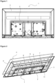
Figure 1 - is the perspective view of a back cover. -
Figure 2 - is the exploded view of a reflector and the back cover. -
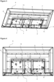
Figure 3 - is the perspective view of the back cover and the reflector. -
Figure 4 - is the front view of the back cover and the reflector. - The elements illustrated in the figures are numbered as follows.
- 1. Back cover
- 2. First base
- 3. First side wall
- 4. Reflector
- 5. Second base
- 6. Second side wall
- 7. Light source
- 8. Light source hole
- 9. Fixing hole
- 10. Fixing group
- 11. Fixing member
- The image display device comprises at least one light source (7); a back cover (1) having a first base (2) whereon the light source (7) is fixed and first side walls (3) surrounding said first base (2); a reflector (4) having a second base (5) and second side walls (6) surrounding said second base (5) and having the same number of light source holes (8) as the light source (7) allowing the light source (7) fixed on the back cover (1) to pass to the other side of the reflector (4); at least two adjacent fixing holes (9) on the second base (5) on the reflector (4); and at least one fixing member (11) remaining between the reflector (4) and the back cover (1) and fixed to the fixing holes (9) and the second side walls (6) (
Figure 1 and Figure 2 ). - In the preferred embodiment of the present invention, the fixing holes (9) have a diameter of maximum 1 mm, and are positioned at the same level in the horizontal axis.
- In another embodiment of the present invention, the fixing member (11) is a rope.
- In another embodiment of the present invention, the insulation element (11) is a strip. In this embodiment of the present invention, the fixing member (11) is in the form of a narrow, flat and thin strip.
- In the preferred embodiment of the present invention, the light source (7) is a LED.
- In an embodiment of the present invention, two adjacent fixing holes (9) in the same horizontal level form a fixing group (10). The fixing member (11) passes from the bottom of the reflector (4) to the top of the reflector (4) through a fixing hole (9), and reaches the bottom of the reflector (4) again through the other fixing hole (9) and passes to the other fixing group (10). In the preferred embodiment of the present invention, there are three fixing groups (10) at the same level, that is, six fixing holes (9). In the embodiment of the present invention, there are nine fixing groups (10) on the reflector (4) such that there are three horizontal lines parallel to each other and three fixing groups (10) on each (
Figure 3 and Figure 4 ). - In the embodiment of the present invention, the light sources (7) are fixed on the back cover (1). The reflector (4) is mounted on the back cover (1) such that the light sources (7) pass through the light source holes (8) on the reflector (4). By means of the reflector (4), the rays emitted behind the LEDs used as light sources (7) are reflected back, thus achieving a homogeneous image. When the reflector (4) is mounted on the back cover (1), the first base (2) of the back cover (1) and the second base (5) of the reflector (4) remain almost on the same surface, below the uppermost points of the light sources (7).
- Due to the position of the fixing member (11) between the reflector (4) and the back cover (1), the fixing member (11) does not adversely affect the brightness, and ensures that the reflector (4) is mounted correctly and smoothly, thus obtaining a homogeneous image.
- In an embodiment of the present invention, the image display device comprises fastening members on the opposite first side walls (3). One end of each of the fixing members (11) is oppositely attached to the fastening members on the first side walls (3).
- In another embodiment of the present invention, as the image display device is placed in a vertical position, the fixing member (11) is glued to prevent the same from falling, slipping or moving. Thus, the reflector (4) comes closer to the back cover (1).
- In the preferred embodiment of the present invention, the image display device is a backlight image display device.
- By means of the present invention, the reflector (4) is properly fixed on the back cover (1), eliminating the risk of operator error. Moreover, since the reflector (4) is properly fitted on the back cover (1), image quality is improved. Furthermore, in cases where the reflector (4) is required to be detached for any reason, the reflector (4) can be used again. Thus, savings in both component costs and time are provided.
Claims (11)
- An image display device comprising at least one light source (7); a back cover (1) having a first base (2) whereon the light source (7) is fixed and first side walls (3) surrounding said first base (2); a reflector (4) having a second base (5) and second side walls (6) surrounding said second base (5) and having the same number of light source holes (8) as the light source (7) allowing the light source (7) fixed on the back cover (1) to pass to the other side of the reflector (4), characterized by at least two adjacent fixing holes (9) on the second base (5) on the reflector (4), and at least one fixing member (11) remaining between the reflector (4) and the back cover (1) and fixed to the fixing holes (9) and the second side walls (6).
- An image display device as in Claim 1, characterized by the fixing holes (9) which have a diameter of maximum 1 mm
- An image display device as in Claim 1 or Claim 2, characterized by the fixing holes (9) which are positioned at the same level in the horizontal axis.
- An image display device as in Claim 1, characterized by the fixing member (11) which is a rope.
- An image display device as in Claim 1, characterized by the fixing member (11) which is a strip.
- An image display device as in Claim 1, characterized by the light source (7) which is a LED.
- An image display device as in Claim 1, characterized by a fixing group (10) which is formed by two adjacent fixing holes (9) in the same horizontal level
- An image display device as in Claim 7, characterized by three fixing groups (10) at the same level.
- An image display device as in Claim 7 and 8, characterized by three horizontal lines parallel to each other and three fixing groups (10) on each.
- An image display device as in Claim 1, characterized by fastening members provided on the opposite first side walls (3).
- An image display device characterized by being of the backlight type.
Applications Claiming Priority (1)
| Application Number | Priority Date | Filing Date | Title |
|---|---|---|---|
| TR202310195 | 2023-08-22 |
Publications (1)
| Publication Number | Publication Date |
|---|---|
| EP4513262A1 true EP4513262A1 (en) | 2025-02-26 |
Family
ID=91737795
Family Applications (1)
| Application Number | Title | Priority Date | Filing Date |
|---|---|---|---|
| EP24185338.1A Withdrawn EP4513262A1 (en) | 2023-08-22 | 2024-06-28 | A backlight image display device |
Country Status (1)
| Country | Link |
|---|---|
| EP (1) | EP4513262A1 (en) |
Citations (5)
| Publication number | Priority date | Publication date | Assignee | Title |
|---|---|---|---|---|
| US8045091B2 (en) | 2006-12-29 | 2011-10-25 | Lg Innotek Co., Ltd. | Backlight unit and dislay device having the same |
| KR20160016020A (en) | 2014-08-01 | 2016-02-15 | 엘지디스플레이 주식회사 | Reflector for uniform brightness and liquid crystal display device having thereof |
| US20170017119A1 (en) * | 2015-07-15 | 2017-01-19 | Hon Hai Precision Industry Co., Ltd. | Backlight module for lcd device |
| CN107238972A (en) | 2017-07-17 | 2017-10-10 | 青岛海信电器股份有限公司 | A kind of down straight aphototropism mode set and display device |
| CN210515977U (en) | 2019-09-30 | 2020-05-12 | 广州视源电子科技股份有限公司 | Reflector plate fixed knot constructs, backlight unit and display device |
-
2024
- 2024-06-28 EP EP24185338.1A patent/EP4513262A1/en not_active Withdrawn
Patent Citations (5)
| Publication number | Priority date | Publication date | Assignee | Title |
|---|---|---|---|---|
| US8045091B2 (en) | 2006-12-29 | 2011-10-25 | Lg Innotek Co., Ltd. | Backlight unit and dislay device having the same |
| KR20160016020A (en) | 2014-08-01 | 2016-02-15 | 엘지디스플레이 주식회사 | Reflector for uniform brightness and liquid crystal display device having thereof |
| US20170017119A1 (en) * | 2015-07-15 | 2017-01-19 | Hon Hai Precision Industry Co., Ltd. | Backlight module for lcd device |
| CN107238972A (en) | 2017-07-17 | 2017-10-10 | 青岛海信电器股份有限公司 | A kind of down straight aphototropism mode set and display device |
| CN210515977U (en) | 2019-09-30 | 2020-05-12 | 广州视源电子科技股份有限公司 | Reflector plate fixed knot constructs, backlight unit and display device |
Similar Documents
| Publication | Publication Date | Title |
|---|---|---|
| US8421971B2 (en) | Liquid crystal display module and one-piece back plate thereof | |
| US8659720B2 (en) | Backlight device and liquid crystal display | |
| US7408599B2 (en) | Backlight assembly comprising a support member corresponding to a hole in a printed circuit board and display device having the same | |
| TWI428670B (en) | A liquid crystal display device for backlighting and a liquid crystal display device using the same | |
| US8197113B2 (en) | Display device | |
| US20130322119A1 (en) | Backlight Module | |
| US20110299006A1 (en) | Flat panel display and method for assembling the flat panel display | |
| KR20060000977A (en) | Backlight Unit of LCD | |
| EP3366988B1 (en) | Display apparatus | |
| WO2015135229A1 (en) | Back plate, backlight module using same, and liquid crystal display device | |
| KR101836484B1 (en) | Backlgiht unit and liquid crystal display device the same | |
| CN104832835A (en) | Backlight module and display | |
| CN102878493B (en) | Backlight module | |
| US20080106670A1 (en) | Backlight module having a fastening structure and liquid crystal display using the same | |
| KR20160147108A (en) | Display device | |
| KR20130051133A (en) | Liquid crystal panel assembly and liquid crystal display apparatus | |
| KR20130115417A (en) | Liquid crystal display device | |
| KR20150145915A (en) | Back-light assembly | |
| US9116277B2 (en) | Lighting device, display device, and television receiver | |
| US20120169942A1 (en) | Lighting device, display device and television receiver | |
| KR101203519B1 (en) | Backlight and liquid crystal display having the same | |
| JP2005251479A (en) | Backlight device, liquid crystal display device, and light source holding member | |
| KR100947527B1 (en) | LCD Display | |
| JP7108484B2 (en) | display device and television receiver | |
| US20150146109A1 (en) | Display device and television device |
Legal Events
| Date | Code | Title | Description |
|---|---|---|---|
| PUAI | Public reference made under article 153(3) epc to a published international application that has entered the european phase |
Free format text: ORIGINAL CODE: 0009012 |
|
| STAA | Information on the status of an ep patent application or granted ep patent |
Free format text: STATUS: REQUEST FOR EXAMINATION WAS MADE |
|
| 17P | Request for examination filed |
Effective date: 20240628 |
|
| AK | Designated contracting states |
Kind code of ref document: A1 Designated state(s): AL AT BE BG CH CY CZ DE DK EE ES FI FR GB GR HR HU IE IS IT LI LT LU LV MC ME MK MT NL NO PL PT RO RS SE SI SK SM TR |
|
| STAA | Information on the status of an ep patent application or granted ep patent |
Free format text: STATUS: THE APPLICATION IS DEEMED TO BE WITHDRAWN |
|
| 18D | Application deemed to be withdrawn |
Effective date: 20250827 |