EP4513234A1 - Parameter configuration method, device, and computer-readable storage medium - Google Patents
Parameter configuration method, device, and computer-readable storage medium Download PDFInfo
- Publication number
- EP4513234A1 EP4513234A1 EP24187073.2A EP24187073A EP4513234A1 EP 4513234 A1 EP4513234 A1 EP 4513234A1 EP 24187073 A EP24187073 A EP 24187073A EP 4513234 A1 EP4513234 A1 EP 4513234A1
- Authority
- EP
- European Patent Office
- Prior art keywords
- receiving units
- group
- view
- receiving
- detection
- Prior art date
- Legal status (The legal status is an assumption and is not a legal conclusion. Google has not performed a legal analysis and makes no representation as to the accuracy of the status listed.)
- Pending
Links
Images



Classifications
-
- G—PHYSICS
- G01—MEASURING; TESTING
- G01S—RADIO DIRECTION-FINDING; RADIO NAVIGATION; DETERMINING DISTANCE OR VELOCITY BY USE OF RADIO WAVES; LOCATING OR PRESENCE-DETECTING BY USE OF THE REFLECTION OR RERADIATION OF RADIO WAVES; ANALOGOUS ARRANGEMENTS USING OTHER WAVES
- G01S7/00—Details of systems according to groups G01S13/00, G01S15/00, G01S17/00
- G01S7/48—Details of systems according to groups G01S13/00, G01S15/00, G01S17/00 of systems according to group G01S17/00
- G01S7/4802—Details of systems according to groups G01S13/00, G01S15/00, G01S17/00 of systems according to group G01S17/00 using analysis of echo signal for target characterisation; Target signature; Target cross-section
-
- G—PHYSICS
- G01—MEASURING; TESTING
- G01S—RADIO DIRECTION-FINDING; RADIO NAVIGATION; DETERMINING DISTANCE OR VELOCITY BY USE OF RADIO WAVES; LOCATING OR PRESENCE-DETECTING BY USE OF THE REFLECTION OR RERADIATION OF RADIO WAVES; ANALOGOUS ARRANGEMENTS USING OTHER WAVES
- G01S17/00—Systems using the reflection or reradiation of electromagnetic waves other than radio waves, e.g. lidar systems
- G01S17/88—Lidar systems specially adapted for specific applications
- G01S17/89—Lidar systems specially adapted for specific applications for mapping or imaging
-
- G—PHYSICS
- G01—MEASURING; TESTING
- G01S—RADIO DIRECTION-FINDING; RADIO NAVIGATION; DETERMINING DISTANCE OR VELOCITY BY USE OF RADIO WAVES; LOCATING OR PRESENCE-DETECTING BY USE OF THE REFLECTION OR RERADIATION OF RADIO WAVES; ANALOGOUS ARRANGEMENTS USING OTHER WAVES
- G01S7/00—Details of systems according to groups G01S13/00, G01S15/00, G01S17/00
- G01S7/48—Details of systems according to groups G01S13/00, G01S15/00, G01S17/00 of systems according to group G01S17/00
- G01S7/497—Means for monitoring or calibrating
-
- G—PHYSICS
- G01—MEASURING; TESTING
- G01S—RADIO DIRECTION-FINDING; RADIO NAVIGATION; DETERMINING DISTANCE OR VELOCITY BY USE OF RADIO WAVES; LOCATING OR PRESENCE-DETECTING BY USE OF THE REFLECTION OR RERADIATION OF RADIO WAVES; ANALOGOUS ARRANGEMENTS USING OTHER WAVES
- G01S17/00—Systems using the reflection or reradiation of electromagnetic waves other than radio waves, e.g. lidar systems
- G01S17/88—Lidar systems specially adapted for specific applications
- G01S17/93—Lidar systems specially adapted for specific applications for anti-collision purposes
- G01S17/931—Lidar systems specially adapted for specific applications for anti-collision purposes of land vehicles
-
- G—PHYSICS
- G01—MEASURING; TESTING
- G01S—RADIO DIRECTION-FINDING; RADIO NAVIGATION; DETERMINING DISTANCE OR VELOCITY BY USE OF RADIO WAVES; LOCATING OR PRESENCE-DETECTING BY USE OF THE REFLECTION OR RERADIATION OF RADIO WAVES; ANALOGOUS ARRANGEMENTS USING OTHER WAVES
- G01S7/00—Details of systems according to groups G01S13/00, G01S15/00, G01S17/00
- G01S7/48—Details of systems according to groups G01S13/00, G01S15/00, G01S17/00 of systems according to group G01S17/00
-
- G—PHYSICS
- G01—MEASURING; TESTING
- G01S—RADIO DIRECTION-FINDING; RADIO NAVIGATION; DETERMINING DISTANCE OR VELOCITY BY USE OF RADIO WAVES; LOCATING OR PRESENCE-DETECTING BY USE OF THE REFLECTION OR RERADIATION OF RADIO WAVES; ANALOGOUS ARRANGEMENTS USING OTHER WAVES
- G01S7/00—Details of systems according to groups G01S13/00, G01S15/00, G01S17/00
- G01S7/48—Details of systems according to groups G01S13/00, G01S15/00, G01S17/00 of systems according to group G01S17/00
- G01S7/483—Details of pulse systems
- G01S7/486—Receivers
- G01S7/4861—Circuits for detection, sampling, integration or read-out
- G01S7/4863—Detector arrays, e.g. charge-transfer gates
-
- Y—GENERAL TAGGING OF NEW TECHNOLOGICAL DEVELOPMENTS; GENERAL TAGGING OF CROSS-SECTIONAL TECHNOLOGIES SPANNING OVER SEVERAL SECTIONS OF THE IPC; TECHNICAL SUBJECTS COVERED BY FORMER USPC CROSS-REFERENCE ART COLLECTIONS [XRACs] AND DIGESTS
- Y02—TECHNOLOGIES OR APPLICATIONS FOR MITIGATION OR ADAPTATION AGAINST CLIMATE CHANGE
- Y02A—TECHNOLOGIES FOR ADAPTATION TO CLIMATE CHANGE
- Y02A90/00—Technologies having an indirect contribution to adaptation to climate change
- Y02A90/10—Information and communication technologies [ICT] supporting adaptation to climate change, e.g. for weather forecasting or climate simulation
Definitions
- This application belongs to the technical field of LiDAR, particularly relating to a parameter configuration method, device, and computer-readable storage medium.
- LiDAR is a key part of achieving autonomous driving, with advantages such as high measurement detection requirements, fine time and space resolution, and long measurement distances. With the development of automotive autonomous driving technology, various types of LiDAR have emerged to meet the needs of different scenarios.
- Embodiments of this application provide a parameter configuration method, device, and computer-readable storage medium, capable of saving storage space for LiDAR.
- an embodiment of this application provides a parameter configuration method, comprising:
- the dividing of the plurality of receiving units in the receiving array of the LiDAR into n groups of receiving units according to a preset rule comprises: according to the preset rule, dividing the plurality of receiving units into the n groups of receiving units based on a field of view range corresponding to the plurality of receiving units.
- the dividing of the plurality of receiving units in the receiving array of the LiDAR into n groups of receiving units according to a preset rule comprises: according to the preset rule, dividing the plurality of receiving units into the n groups of receiving units based on row numbers and/or column numbers of the plurality of receiving units.
- the setting of the measurement range for the i th group of receiving units of the n groups of receiving units according to the detection requirement corresponding to the i th group of receiving units comprises:
- the method further comprises: setting a sampling rate of the i th group of receiving units on different segments in the measurement range, according to the detection requirement corresponding to the i th group of receiving units.
- the method further comprises: selecting the measurement data of the i th group of receiving units according to a detection situation of the i th group of receiving units.
- the fields of view corresponding to the plurality of receiving units comprise horizontal and vertical detection fields of view, and the method further comprises:
- an embodiment of this application provides a parameter configuration device, comprising: a grouping module, configured to divide a plurality of receiving units in a receiving array of a LiDAR into n groups of receiving units according to a preset rule, wherein each of the n groups of receiving units comprises at least one receiving unit, and n is a positive integer greater than or equal to 1; and a setting module, configured to set a measurement range for an i th group of receiving units of the n groups of receiving units according to a detection requirement corresponding to the i th group of receiving units, wherein i is a positive integer, and i is in a range of [1, n].
- an embodiment of this application provides a parameter configuration device, comprising: a processor and a memory; wherein the memory stores a computer program, which is configured to be loaded and executed by the processor to perform the method embodiments.
- an embodiment of this application provides a computer-readable storage medium, which stores a computer program, the computer program being executed by a processor to implement the method embodiments.
- different measurement ranges can be set for different groups of receiving units according to detection requirements, reducing unnecessary data measurements and saving storage space.
- the measurement range needs to be set relatively large to meet business requirements. For those receiving units that do not need to measure relatively far distances, a large measurement range will have unnecessary sampling data, still requiring a large storage area for these receiving units, resulting in a waste of storage space. Setting different measurement ranges for different groups of receiving units according to actual detection requirements can reduce the total amount of measurement data and save the storage space for measurement data.
- LiDAR comprises an array of emitter units and an array of receiver units. It can simultaneously acquire point cloud data from multiple angles and is widely used in fields such as autonomous driving, robotics, and drones. LiDAR can also be referred to as array-type LiDAR, array-based LiDAR, etc.
- the LiDAR includes an emission array (array emitter) and a reception array (array receiver).
- the emission array comprises multiple emitting units
- the reception array comprises multiple receiving units.
- the quantity of emitting units can be set to be the same as the quantity of receiving units, each emitting unit corresponds to one receiving unit.
- one emitting unit corresponds to multiple receiving units, or multiple emitting units correspond to one receiving unit.
- a LiDAR generally comprises multiple groups of emitting unit and receiving unit pairs, which generate a large amount of detection data. This data will occupy a large amount of storage space.
- a LiDAR has rotating components, such as a rotary drive platform; or scanning components, such as a rotating mirror, galvanometer, or a combination of both.
- a parameter configuration method in which the receiving units in the LiDAR's receiving array are grouped according to a preset rule. Based on detection requirements, the measurement range corresponding to each group of receiving units is set, thereby reducing the amount of measurement data acquired by some receiving units in unnecessary measurement ranges, reducing the data volume of measurement data, and saving storage space.
- a method 200 includes the following steps: S210: Dividing the plurality of receiving units in the receiving array of the LiDAR into n groups of receiving units according to a preset rule.
- the plurality of receiving units in the receiving array of the LiDAR is divided into n groups according to a preset rule, wherein each group of receiving units comprises at least one receiving unit, n is a positive integer greater than or equal to 1.
- Receiving units can be avalanche photodiodes (APDs), single-photon avalanche diodes (SPADs), or silicon photomultipliers (SIPMs).
- APDs avalanche photodiodes
- SPADs single-photon avalanche diodes
- SIPMs silicon photomultipliers
- each receiving unit has a corresponding emitting unit, so dividing the receiving units into n groups can also be dividing the emitting and receiving unit pairs into n groups.
- the emitting and receiving unit pair here refers to a receiving unit and one or more corresponding emitting units.
- the plurality of emitting units in the LiDAR's emission array can be divided into n groups according to a preset rule, wherein each group of emitting units includes at least one emitting unit.
- the receiving units can be grouped, the emitting and receiving unit pairs can be grouped, or the emitting units can be grouped.
- An embodiment is disclosed to illustrate possible implementations of grouping multiple receiving units according to preset rules.
- the preset rule can be to group the multiple receiving units based on their physical arrangement. In an embodiment, grouping the multiple receiving units based on preset rules can be to divide the multiple receiving units into n groups based on their row numbers and/or column numbers.
- the receiving units can be grouped according to their row numbers.
- a receiving array of the LiDAR includes 96 receiving units in total, arranged in an 8 ⁇ 12 array, with row numbers labeled A ⁇ H and column numbers labeled 0 ⁇ 11.
- Each receiving unit can be uniquely identified by its row and column numbers.
- the receiving unit in the first row and first column can be identified as A0
- the receiving unit in the second row and second column can be identified as B1.
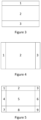
- the 96 receiving units can be grouped based on row numbers, as shown in Figure 3 .
- the 96 receiving units are divided into 3 groups based on their row numbers: the receiving units in rows A and B are grouped as the first group, the receiving units in rows C ⁇ F are grouped as the second group, and the receiving units in rows G and H are grouped as the third group.
- grouping the receiving units according to their column numbers is disclosed. Taking the receiving array shown in Figure 1 as an example: according to the preset rule, the 96 receiving units in the receiving array can be grouped based on column numbers, as shown in Figure 4 . In the grouping result shown in Figure 4 , the 96 receiving units are divided into 3 groups based on their column numbers: the receiving units in columns 0 and 1 are grouped as the first group, the receiving units in columns 2 ⁇ 9 are grouped as the second group, and the receiving units in columns 10 and 11 are grouped as the third group.
- the receiving units can be grouped according to both row and column numbers. Taking the receiving array shown in Figure 5 as an example: according to the preset rule, the 96 receiving units in the receiving array can be grouped based on both row and column numbers, as shown in Figure 5 . In the grouping result shown in Figure 5 , the 96 receiving units are divided into 9 groups based on both row and column numbers: the receiving units in rows G and H and columns 0 and 1 are grouped as the first group, the receiving units in rows G and H and columns 2 ⁇ 9 are grouped as the second group, the receiving units in rows G and H and columns 10 and 11 are grouped as the third group, and so on.
- the multiple receiving units can be divided into n groups based on their fields of view according to a preset rule.
- the field of view of a receiving unit refers to the area illuminated by the laser beam emitted by the corresponding emitting unit.
- the receiving units can be grouped according to their vertical fields of view.
- the vertical field of view is divided into three parts according to the preset rule: the receiving units corresponding to the vertical field of view range of 0° ⁇ 30° are grouped as the first group, the receiving units corresponding to the vertical field of view range of 30° ⁇ 150° are grouped as the second group, and the receiving units corresponding to the vertical field of view range of 150° ⁇ 180° are grouped as the third group.
- the vertical field of view range of 0° ⁇ 30° corresponds to a field of view inclined towards the ground
- the vertical field of view range of 30° ⁇ 150° corresponds to a middle field of view
- the vertical field of view range of 150° ⁇ 180° corresponds to a field of view inclined towards the sky.
- the receiving units inclined towards different areas can be grouped, facilitating the setting of different measurement ranges for the receiving units inclined towards different areas.
- the setting of measurement ranges can be referred to in the subsequent description of step S210.
- the receiving units can be grouped according to their horizontal fields of view.
- the horizontal field of view is divided into three parts according to the preset rule: the receiving units corresponding to the horizontal field of view range of 0° ⁇ 30° are grouped as the first group, the receiving units corresponding to the horizontal field of view range of 30° ⁇ 150° are grouped as the second group, and the receiving units corresponding to the horizontal field of view range of 150° ⁇ 180° are grouped as the third group.
- the receiving units can be grouped according to both their vertical and horizontal fields of view.
- the vertical and horizontal fields of view are divided into 9 parts according to the preset rule: the receiving units corresponding to the vertical field of view range of 0° ⁇ 30° and the horizontal field of view range of 0° ⁇ 30° are grouped as the first group, the receiving units corresponding to the vertical field of view range of 0° ⁇ 30° and the horizontal field of view range of 30° ⁇ 150° are grouped as the second group, the receiving units corresponding to the vertical field of view range of 0° ⁇ 30° and the horizontal field of view range of 150° ⁇ 180° are grouped as the third group, and so on.
- Embodiments shown in Figures 3 to 5 divide the field of view regions into rectangular parts.
- the field of view regions can be divided into other shapes, such as annular shapes, as shown in Figure 6 .
- the receiving units can be receiving arrays, or they can be receiving line arrays. In an embodiment, the multiple receiving units can be regularly arranged or irregularly arranged.
- the receiving units are multiple line arrays
- the partition corresponding to the position of the multiple line arrays can be different, or when the receiving units are array arrays, the receiving units in different columns or rows can correspond to different partitions.
- Figure 7 includes four receiving line arrays (receiving line array 701, receiving line array 702, receiving line array 703, receiving line array 704).
- Each receiving line array is divided into three groups according to the vertical field of view of the receiving units.
- the receiving line arrays 701 and 704 are located at the edge of the horizontal field of view detection range, the quantity of receiving units in the vertical field of view detection range corresponding to the central partition (such as 2 and 12) can be fewer than the receiving line arrays 702 and 703 located in the central field of the horizontal field of view detection range.
- the partitions can be adjusted according to the horizontal field of view detection range.
- the storage space can be saved while further ensuring the detection requirements.
- the grouping of the receiving units can be adjusted based on the detection range of the horizontal field of view of all or part of the area.
- the grouping of the receiving units can be adjusted based on the detection range of the vertical field of view of all or part of the area.
- Grouping of the receiving arrays based on the detection range of the vertical field of view or the horizontal field of view depends on the system's detection resolution requirements for the horizontal or vertical field of view.
- the field of view with higher detection requirements can be selected to group the receiving arrays first, and then the grouping of the receiving arrays can be adjusted based on the field of view with relatively lower detection requirements.
- part of the receiving units in the receiving arrays are grouped based on the above methods.
- S220 Setting the measurement range of the i th group of receiving units, according to the detection requirement corresponding to the i th group of receiving units in the n groups of receiving units.
- the measurement range or detection resolution can be set according to the detection requirements corresponding to each group of receiving units. In an embodiment, for a field of view area with a smaller required measurement range, a smaller measurement range and lower detection resolution can be set for the receiving units corresponding to that field of view area. In an embodiment, for a field of view area with a larger required measurement range, a larger measurement range and higher detection resolution can be set for the receiving units corresponding to that field of view area.
- a receiving array is divided into three groups based on the vertical field of view ranges of 0° ⁇ 30°, 30° ⁇ 150°, and 150° ⁇ 180°.
- the vertical field of view range of 0° ⁇ 30° corresponds to a field of view inclined towards the ground
- the vertical field of view range of 30° ⁇ 150° corresponds to a middle field of view
- the vertical field of view range of 150° ⁇ 180° corresponds to a field of view inclined towards the sky. Since the fields of view inclined towards the ground and the sky have shorter detection distances and lower detection requirements, only a small storage space is needed to store sampling data.
- the field of view inclined towards the middle has a longer detection distance and higher detection requirements, so a larger storage space is needed to store sampling data.
- the storage space is used to store the measurement data of the i th group of receiving units, where i is a positive integer, and i G [1, n].
- the measurement range of the i th group of receiving units is large and the measurement detection requirements are high, a larger storage space can be set for the i th group of receiving units. If the measurement range of the i th group of receiving units is small and the measurement detection requirements are low, a smaller storage space can be set for the i th group of receiving units.
- the limited storage space can be reasonably allocated, avoiding the situation where some receiving units with fewer data occupy larger storage space, which leads to a waste of storage space, and reducing the occurrence of insufficient storage space for some receiving units due to uneven distribution of storage space.
- the measurement range and/or measurement detection requirements for each group of receiving units can be pre-configured according to the known usage of the receiving units in the LiDAR.
- measurement range for each group of receiving units can be adaptively adjusted.
- for the i th group of receiving units obtain the maximum measurement range and/or average measurement range corresponding to the previous frame measurement data of the i th group of receiving units, obtain the historical measurement range corresponding to the historical measurement data of the i th group of receiving units within a preset time range, and then set the measurement range and detection accuracy for the current frame of the i th group of receiving units based on the maximum measurement range and/or average measurement range and historical measurement range.
- obtain the maximum measurement range and/or average measurement range corresponding to the measurement data of the i th group of receiving units within a preset time range obtain the historical measurement range corresponding to the historical measurement data of the i th group of receiving units, and then set the measurement range and detection accuracy for the current frame of the i th group of receiving units based on the maximum measurement range and/or average measurement range and historical measurement range.
- the preset time range is related to the scanning method of the LiDAR, statistics on the maximum measurement range and/or average measurement range are needed after the detection area corresponding to the i th group of receiving units is detected.
- the statistical period can correspond to one detection cycle or a preset quantity of detection cycles.
- the preset time can be the time required for the i th group of receiving units to complete detection in one detection cycle.
- the preset time can be the time required for the i th group of receiving units to complete detection in a preset quantity of detection cycles.
- a size of the preset time is related to the detection requirements of the i th group of receiving units, the larger the detection distance and higher the detection accuracy requirements of the i th group of receiving units, the shorter the required preset time, further accurately optimizing the storage space of the receiving units with high detection requirements or large detection distances.
- the smaller the detection distance and lower the detection accuracy requirements of the i th group of receiving units the longer the required preset time, thereby reducing the number of data statistics cycles for areas with shorter detection distances or lower detection requirements, reducing the computational load of the LiDAR.
- the method before obtaining the maximum measurement range corresponding to the detection area of the i th group of units, includes: obtaining the detection distance value corresponding to each receiving unit in the i th group of receiving units, determining the difference between the detection distance value corresponding to each receiving unit and the detection distance of adjacent receiving units, and if the difference exceeds a first preset value, based on a continuous preset number of times, confirm the difference between the distance value corresponding to each receiving unit and the adjacent receiving unit, and if the difference exceeds the first preset value for the preset number of times, adjust the grouping of the receiving units in that area.
- measurement results of all pixels in the current area are obtained, and the historical measurement range corresponding to the current area are obtained.
- the maximum measurement range in the current area is determined based on the measurement results of all pixels, and the actual required measurement range is statistically analyzed based on the maximum measurement range and historical measurement range.
- the measurement range required for the i th group of receiving units is adjusted.
- the storage units corresponding to the i th group of receiving units is adjusted based on the measurement range of the i th group of receiving units.
- the measurement range of the i th group of receiving units is comprehensively determined, so that the measurement range of the i th group of receiving units not only meets the trend of historical measurement data but also meets the requirements of current measurement data, avoiding the situation where the determined measurement range is too small to meet current business requirements or too large, leading to excessive measurement data and occupying excessive storage space.
- a parameter configuration method reduces the amount of measurement data by setting different sampling rates for different measurement distances.
- this method includes: setting different sampling rates on different segments in the measurement range, based on the detection requirements corresponding to the i th group of receiving units. In an embodiment, a higher sampling rate is set in the segments with higher accuracy requirements, and a lower sampling rate is set in the segments with lower accuracy requirements.
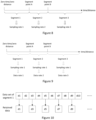
- the implementation of this scheme is illustrated in Figure 8 .
- segment points can be set to divide the measurement range or flight time into multiple segments (e.g., segment 1, segment 2, segment 3), and different sampling rates are set for each segment (e.g., segment 1 corresponds to sampling rate 1, segment 2 corresponds to sampling rate 2, segment 3 corresponds to sampling rate 3).
- the segment points can be set according to the detection requirements.
- the measurement detection requirement is relatively high within 0 ⁇ 30m
- the measurement detection requirement is average within 30 ⁇ 60m
- the measurement detection requirement is relatively low within 60 ⁇ 100m, so segment points can be set at 30m and 60m in the measurement range.
- the sampling rate can be reduced in areas with low accuracy requirements, thereby reducing the amount of measurement data.
- different data sampling rates can be used within different flight times, such as setting segment 1 within the range of 0 ⁇ 0.4 microseconds, using a sampling rate of 4Gsps; setting segment 2 within the range of 0.4 ⁇ 0.8 microseconds, using a sampling rate of 2Gsps; setting segment 3 within the range of 0.8 ⁇ 1.2 microseconds, using a sampling rate of 1Gsps.
- the number of items of sampled data equals to the segment's duration multiplied by the corresponding segment sampling rate.
- using a combination of high and low sampling rates allows for fewer measurement data items compared to using a high sampling rate throughout, saving storage space.
- the combination of high and low sampling rates is beneficial for optimizing the storage space of the LiDAR, saving the storage space of the receiving units.
- a parameter configuration method reduces the amount of measurement data by setting different data rates for different measurement distances.
- this method includes: screening the measurement data of the i th group of receiving units according to the detection situation of the i th group of receiving units. In an embodiment, in segments with high accuracy requirements, data is not screened, or a large amount of data is screened; in segments with low accuracy requirements, less data is screened. The implementation of this scheme is illustrated in Figures 9 and 10 .
- segment points can be set to divide the measurement range or flight time into multiple segments (e.g., segment 1, segment 2, segment 3), and the same sampling rate is set for each segment (e.g., segments 1, 2, and 3 all correspond to sampling rate 1).
- Different data rates are set for each segment.
- the data rate here can be understood as the proportion of data retained after screening, for example, a data rate of 70% means that 30 out of 100 data points are deleted, and 70 data points are retained. Referring to Figure 10 , assuming the data rate for the data set collected in segment 1 is 50%, 50% of the data needs to be screened. In the example shown in Figure 10 , every other data point is retained by deleting every second data point, i.e., d1 is retained while d2 is deleted,, d3 is retained while d4 is deleted, and so on.
- the same sampling rate is used for each segment, and the sampled data is used as the screened measurement data.
- part of the data in all segments is extracted and screened, reducing the storage space occupied by all the data and optimizing the storage space.
- the embodiments of this application also provide corresponding devices.
- the devices include modules for performing the corresponding methods in each embodiment.
- the modules can be software, hardware, or a combination of software and hardware.
- the technical features described in the method embodiments are also applicable to the device embodiments.
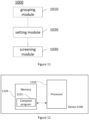
- FIG 11 shows a structural block diagram of the device 1000 provided in the embodiments of this application.
- the device includes the following modules:
- the grouping module 1010 is used to divide the plurality of receiving units into n groups based on their fields of view according to the preset rule.
- the grouping module 1010 is used to divide the plurality of receiving units into n groups based on their row numbers and/or column numbers according to the preset rule.
- the setting module 1020 is used to obtain the maximum measurement range of the current measurement data of the i th group of receiving units and the historical measurement range corresponding to the historical measurement data. Based on the maximum measurement range and the historical measurement range, the measurement range of the i th group of receiving units is set.
- the setting module 1020 is used to set different sampling rates on different segments within the measurement range based on the detection requirements corresponding to the i th group of receiving units.
- the device includes a screening module 1030, used to screen the measurement data of the i th group of receiving units according to the detection situation of the i th group of receiving units.
- the above functional units and modules are described as examples.
- the functions described above can be distributed among different functional units or modules as needed, the internal structure of the device can be divided into different functional units or modules to complete all or part of the functions described above.
- the functional units and modules in the embodiments can be integrated into one processing unit, or they can be physically separate units. They can also be integrated into one unit with two or more units.
- the integrated units can be implemented in hardware form, or in software functional units.
- the names of the functional units and modules are for convenience in distinguishing them.
- the working process of the units and modules in the above-mentioned system can be referred to in the corresponding process in the method embodiments described earlier.
- an embodiment of this application also provides a device 1100.
- the device 1100 includes: at least one processor 1110, a memory 1120, and a computer program 1121 stored in the memory and operable on the at least one processor.
- the processor executes the computer program, the steps of any of the method embodiments.
- An embodiment of this application also provides a computer-readable storage medium.
- the computer-readable storage medium stores a computer program, which, when executed by a processor, implements the steps of any of the method embodiments.
- An embodiment of this application provides a computer program product.
- the computer program product When the computer program product is run on an electronic device, it causes a mobile terminal to implement the steps of any of the method embodiments.
- the integrated units are implemented as software functional units and sold or used as standalone products, they can be stored in a computer-readable storage medium. Based on this understanding, all or part of the processes in the methods of the embodiments described above can be implemented by instructing related hardware via a computer program.
- the computer program can be stored in a computer-readable storage medium, and when executed by a processor, the steps of any of the method embodiments described above are implemented.
- the computer program includes computer program code, which can be in the form of source code, object code, executable files, or some intermediate form.
- the computer-readable medium can include any entity or device capable of carrying the computer program code, such as a recording medium, a computer memory, a read-only memory (ROM), a random access memory (RAM), an electric carrier signal, an electrical signal, and a software distribution medium, for example, a USB flash drive, a mobile hard disk, a magnetic disk, or an optical disk.
- a computer-readable medium cannot be an electric carrier signal or an electrical signal.
- the disclosed devices, network equipment, and methods can be implemented in other ways.
- the devices or network equipment described above are merely illustrative.
- the division of modules or units is only one logical functional division. In actual implementation, there can be other divisions.
- multiple units or components can be combined or integrated into another system, or some features can be omitted or not executed.
- the coupling or direct coupling or communication connection between the displayed or discussed units or modules can be through some interfaces, devices, or unit indirect coupling or communication connections, which can be electrical, mechanical, or other forms.
Landscapes
- Engineering & Computer Science (AREA)
- Physics & Mathematics (AREA)
- Computer Networks & Wireless Communication (AREA)
- General Physics & Mathematics (AREA)
- Radar, Positioning & Navigation (AREA)
- Remote Sensing (AREA)
- Electromagnetism (AREA)
- Optical Radar Systems And Details Thereof (AREA)
Abstract
Description
- This application belongs to the technical field of LiDAR, particularly relating to a parameter configuration method, device, and computer-readable storage medium.
- LiDAR is a key part of achieving autonomous driving, with advantages such as high measurement detection requirements, fine time and space resolution, and long measurement distances. With the development of automotive autonomous driving technology, various types of LiDAR have emerged to meet the needs of different scenarios.
- As autonomous driving technology advances towards high precision, the accuracy of LiDAR increases, resulting in a significant increase in the amount of detection data that needs to be stored and processed. Such measurement data occupies a large amount of storage space.
- Embodiments of this application provide a parameter configuration method, device, and computer-readable storage medium, capable of saving storage space for LiDAR.
- In a first aspect, an embodiment of this application provides a parameter configuration method, comprising:
- dividing a plurality of receiving units in a receiving array of a LiDAR into n groups of receiving units according to a preset rule, wherein each of the n groups of receiving units comprises at least one receiving unit, and n is a positive integer greater than or equal to 1;
- setting a measurement range for an ith group of receiving units of the n groups of receiving units according to a detection requirement corresponding to the ith group of receiving units, wherein i is a positive integer, and i is in a range of [1, n];
- setting a storage space for the ith group of receiving units according to the measurement range of the ith group of receiving units, wherein the storage space is used to store measurement data of the ith group of receiving units.
- In an embodiment, the dividing of the plurality of receiving units in the receiving array of the LiDAR into n groups of receiving units according to a preset rule comprises: according to the preset rule, dividing the plurality of receiving units into the n groups of receiving units based on a field of view range corresponding to the plurality of receiving units.
- In an embodiment, the dividing of the plurality of receiving units in the receiving array of the LiDAR into n groups of receiving units according to a preset rule comprises: according to the preset rule, dividing the plurality of receiving units into the n groups of receiving units based on row numbers and/or column numbers of the plurality of receiving units.
- In an embodiment, the setting of the measurement range for the ith group of receiving units of the n groups of receiving units according to the detection requirement corresponding to the ith group of receiving units comprises:
- obtaining a maximum measurement range corresponding to current measurement data of the ith group of receiving units and a historical measurement range corresponding to historical measurement data;
- setting the measurement range for the ith group of receiving units according to the maximum measurement range and the historical measurement range.
- In an embodiment, the method further comprises: setting a sampling rate of the ith group of receiving units on different segments in the measurement range, according to the detection requirement corresponding to the ith group of receiving units.
- In an embodiment, the method further comprises: selecting the measurement data of the ith group of receiving units according to a detection situation of the ith group of receiving units.
- In an embodiment, the fields of view corresponding to the plurality of receiving units comprise horizontal and vertical detection fields of view, and the method further comprises:
- determining detection resolution requirements of the horizontal and vertical detection fields of view;
- if the detection resolution requirement of the horizontal detection field of view is high;
- grouping the plurality of receiving units according to the field of view range of the horizontal detection field of view;
- adjusting the grouping of the plurality of receiving units according to the field of view range of the vertical detection field of view;
- if the detection resolution requirement of the vertical detection field of view is high;
- grouping the plurality of receiving units according to the field of view range of the vertical detection field of view;
- adjusting the grouping of the plurality of receiving units according to the field of view range of the horizontal detection field of view.
- In a second aspect, an embodiment of this application provides a parameter configuration device, comprising: a grouping module, configured to divide a plurality of receiving units in a receiving array of a LiDAR into n groups of receiving units according to a preset rule, wherein each of the n groups of receiving units comprises at least one receiving unit, and n is a positive integer greater than or equal to 1; and a setting module, configured to set a measurement range for an ith group of receiving units of the n groups of receiving units according to a detection requirement corresponding to the ith group of receiving units, wherein i is a positive integer, and i is in a range of [1, n].
- In a third aspect, an embodiment of this application provides a parameter configuration device, comprising: a processor and a memory; wherein the memory stores a computer program, which is configured to be loaded and executed by the processor to perform the method embodiments.
- In a fourth aspect, an embodiment of this application provides a computer-readable storage medium, which stores a computer program, the computer program being executed by a processor to implement the method embodiments.
- By grouping the receiving units, different measurement ranges can be set for different groups of receiving units according to detection requirements, reducing unnecessary data measurements and saving storage space. In an embodiment, if the same measurement range is set for all receiving units in the LiDAR receiving array, the measurement range needs to be set relatively large to meet business requirements. For those receiving units that do not need to measure relatively far distances, a large measurement range will have unnecessary sampling data, still requiring a large storage area for these receiving units, resulting in a waste of storage space. Setting different measurement ranges for different groups of receiving units according to actual detection requirements can reduce the total amount of measurement data and save the storage space for measurement data.
- To more clearly illustrate the technical solutions of the embodiments of this application, the accompanying drawings required for describing the embodiments will be briefly introduced below.
-
Figure 1 is a structural schematic diagram of an emission array and a receiving array of a LiDAR provided in an embodiment; -
Figure 2 is a schematic flow chart of a parameter configuration method provided in an embodiment; -
Figure 3 is a schematic diagram of grouping receiving units provided in an embodiment; -
Figure 4 is another schematic diagram of grouping receiving units provided in an embodiment; -
Figure 5 is yet another schematic diagram of grouping receiving units provided in an embodiment; -
Figure 6 is yet another schematic diagram of grouping receiving units provided in an embodiment; -
Figure 7 is a schematic diagram of multiple line arrays provided in an embodiment; -
Figure 8 is a schematic diagram for configuring sampling rates provided in an embodiment; -
Figure 9 is a schematic diagram for configuring data rates provided in an embodiment; -
Figure 10 is a schematic diagram for screening measurement data provided in an embodiment; -
Figure 11 is a structural schematic diagram of a parameter configuration device provided in an embodiment; -
Figure 12 is another structural schematic diagram of a parameter configuration device provided in an embodiment; -
Figure 13 is a schematic flow chart of adaptively adjusting the measurement range provided in an embodiment. - To make the objectives, technical solutions, and advantages of the embodiments of this application clearer, the technical solutions in the embodiments of this application will be described clearly below with reference to the accompanying drawings in the embodiments of this application.
- The terms "first", "second", "third", "fourth", and other similar terms in the description, claims, and drawings of this application (if present) are used to distinguish similar objects and are not necessarily used to describe specific sequences or orders. The data used in this way can be interchanged appropriately under certain circumstances to allow the embodiments described herein to be implemented in a sequence other than that illustrated or described herein. Additionally, the terms "comprise" and "include" as well as their any variations, are intended to cover non-exclusive inclusion, for example, a process, method, system, product, or device comprising a series of steps or units is not necessarily limited to those clearly listed steps or units, but may include other steps or units that are not clearly listed or inherent to these processes, methods, products, or devices.
- In the description of the embodiments of this application, unless otherwise specified, "/" indicates "or", for example, A/B can mean A or B; "and/or" herein only describes an associative relationship of related objects, indicating that there may be three types of relationships, for example, A and/or B can mean: only A exists, both A and B exist, and only B exists. Additionally, in the description of the embodiments of this application, "multiple" or "plurality" refers to two or more.
- The operation methods in the method embodiments of this application can also be applied to the device embodiments or system embodiments.
- In embodiment of this application, unless otherwise specified and logical conflict is avoided, the terminology and/or descriptions in different embodiments are consistent and can be referenced to each other, and the technical features in different embodiments can be combined to form new embodiments based on their inherent logical relationships.
- Various numerical identifiers involved in embodiment are only for distinguishing convenience. The sizes of the serial numbers of the aforementioned processes do not imply the order of execution, and the order of execution of each process should be determined by its function and intrinsic logic.
- LiDAR comprises an array of emitter units and an array of receiver units. It can simultaneously acquire point cloud data from multiple angles and is widely used in fields such as autonomous driving, robotics, and drones. LiDAR can also be referred to as array-type LiDAR, array-based LiDAR, etc.
- In an embodiment, as shown in
Figure 1 , the LiDAR includes an emission array (array emitter) and a reception array (array receiver). The emission array comprises multiple emitting units, and the reception array comprises multiple receiving units. In an embodiment, the quantity of emitting units can be set to be the same as the quantity of receiving units, each emitting unit corresponds to one receiving unit. In an embodiment, one emitting unit corresponds to multiple receiving units, or multiple emitting units correspond to one receiving unit. - When the LiDAR detection accuracy requirement increases, the quantity of emission and reception channels of the LiDAR also increases. Therefore, a LiDAR generally comprises multiple groups of emitting unit and receiving unit pairs, which generate a large amount of detection data. This data will occupy a large amount of storage space. In an embodiment, a LiDAR has rotating components, such as a rotary drive platform; or scanning components, such as a rotating mirror, galvanometer, or a combination of both.
- In an embodiment, a parameter configuration method is provided, in which the receiving units in the LiDAR's receiving array are grouped according to a preset rule. Based on detection requirements, the measurement range corresponding to each group of receiving units is set, thereby reducing the amount of measurement data acquired by some receiving units in unnecessary measurement ranges, reducing the data volume of measurement data, and saving storage space.
- In an embodiment, as shown in
Figure 2 , amethod 200 includes the following steps:
S210: Dividing the plurality of receiving units in the receiving array of the LiDAR into n groups of receiving units according to a preset rule. - In an embodiment, the plurality of receiving units in the receiving array of the LiDAR is divided into n groups according to a preset rule, wherein each group of receiving units comprises at least one receiving unit, n is a positive integer greater than or equal to 1.
- Receiving units can be avalanche photodiodes (APDs), single-photon avalanche diodes (SPADs), or silicon photomultipliers (SIPMs).
- In an embodiment, each receiving unit has a corresponding emitting unit, so dividing the receiving units into n groups can also be dividing the emitting and receiving unit pairs into n groups. The emitting and receiving unit pair here refers to a receiving unit and one or more corresponding emitting units.
- In an embodiment, the plurality of emitting units in the LiDAR's emission array can be divided into n groups according to a preset rule, wherein each group of emitting units includes at least one emitting unit. The receiving units can be grouped, the emitting and receiving unit pairs can be grouped, or the emitting units can be grouped.
- An embodiment is disclosed to illustrate possible implementations of grouping multiple receiving units according to preset rules.
- In an embodiment, the preset rule can be to group the multiple receiving units based on their physical arrangement. In an embodiment, grouping the multiple receiving units based on preset rules can be to divide the multiple receiving units into n groups based on their row numbers and/or column numbers.
- In an embodiment, the receiving units can be grouped according to their row numbers. In an embodiment, a receiving array of the LiDAR includes 96 receiving units in total, arranged in an 8×12 array, with row numbers labeled A~H and column numbers labeled 0~11. Each receiving unit can be uniquely identified by its row and column numbers. For example, the receiving unit in the first row and first column can be identified as A0, and the receiving unit in the second row and second column can be identified as B1. According to the preset rule, the 96 receiving units can be grouped based on row numbers, as shown in
Figure 3 . In a grouping result shown inFigure 3 , the 96 receiving units are divided into 3 groups based on their row numbers: the receiving units in rows A and B are grouped as the first group, the receiving units in rows C~F are grouped as the second group, and the receiving units in rows G and H are grouped as the third group. - In an embodiment, grouping the receiving units according to their column numbers is disclosed. Taking the receiving array shown in
Figure 1 as an example: according to the preset rule, the 96 receiving units in the receiving array can be grouped based on column numbers, as shown inFigure 4 . In the grouping result shown inFigure 4 , the 96 receiving units are divided into 3 groups based on their column numbers: the receiving units incolumns columns 2~9 are grouped as the second group, and the receiving units incolumns - In an embodiment, the receiving units can be grouped according to both row and column numbers. Taking the receiving array shown in
Figure 5 as an example: according to the preset rule, the 96 receiving units in the receiving array can be grouped based on both row and column numbers, as shown inFigure 5 . In the grouping result shown inFigure 5 , the 96 receiving units are divided into 9 groups based on both row and column numbers: the receiving units in rows G and H andcolumns columns 2~9 are grouped as the second group, the receiving units in rows G and H andcolumns - In an embodiment, the multiple receiving units can be divided into n groups based on their fields of view according to a preset rule. Here, the field of view of a receiving unit refers to the area illuminated by the laser beam emitted by the corresponding emitting unit.
- In an embodiment, the receiving units can be grouped according to their vertical fields of view. The vertical field of view is divided into three parts according to the preset rule: the receiving units corresponding to the vertical field of view range of 0°~30° are grouped as the first group, the receiving units corresponding to the vertical field of view range of 30°~150° are grouped as the second group, and the receiving units corresponding to the vertical field of view range of 150°~180° are grouped as the third group. In an embodiment, the vertical field of view range of 0°~30° corresponds to a field of view inclined towards the ground, the vertical field of view range of 30°~150° corresponds to a middle field of view, and the vertical field of view range of 150°~180° corresponds to a field of view inclined towards the sky. The receiving units inclined towards different areas can be grouped, facilitating the setting of different measurement ranges for the receiving units inclined towards different areas. The setting of measurement ranges can be referred to in the subsequent description of step S210.
- In an embodiment, the receiving units can be grouped according to their horizontal fields of view. In an embodiment, the horizontal field of view is divided into three parts according to the preset rule: the receiving units corresponding to the horizontal field of view range of 0°~30° are grouped as the first group, the receiving units corresponding to the horizontal field of view range of 30°~150° are grouped as the second group, and the receiving units corresponding to the horizontal field of view range of 150°~180° are grouped as the third group.
- In an embodiment, the receiving units can be grouped according to both their vertical and horizontal fields of view. In an embodiment, the vertical and horizontal fields of view are divided into 9 parts according to the preset rule: the receiving units corresponding to the vertical field of view range of 0°~30° and the horizontal field of view range of 0°~30° are grouped as the first group, the receiving units corresponding to the vertical field of view range of 0°~30° and the horizontal field of view range of 30°~150° are grouped as the second group, the receiving units corresponding to the vertical field of view range of 0°~30° and the horizontal field of view range of 150°~180° are grouped as the third group, and so on.
- Embodiments shown in
Figures 3 to 5 divide the field of view regions into rectangular parts. In an embodiment, the field of view regions can be divided into other shapes, such as annular shapes, as shown inFigure 6 . - In an embodiment, the receiving units can be receiving arrays, or they can be receiving line arrays. In an embodiment, the multiple receiving units can be regularly arranged or irregularly arranged.
- In an embodiment, the receiving units are multiple line arrays, the partition corresponding to the position of the multiple line arrays can be different, or when the receiving units are array arrays, the receiving units in different columns or rows can correspond to different partitions.
- In an embodiment, as shown in
Figure 7, Figure 7 includes four receiving line arrays (receivingline array 701, receivingline array 702, receivingline array 703, receiving line array 704). Each receiving line array is divided into three groups according to the vertical field of view of the receiving units. Thereceiving line arrays receiving line arrays - By dividing the receiving array into partitions based on the detection range of the vertical field of view or the horizontal field of view, and then adjusting the grouping of the receiving units based on the detection range of the horizontal or vertical field of view, the storage space can be saved while further ensuring the detection requirements.
- In an embodiment, as shown in
Figure 3 , after the receiving arrays are grouped based on the detection range of the vertical field of view, the grouping of the receiving units can be adjusted based on the detection range of the horizontal field of view of all or part of the area. In an embodiment, as shown inFigure 4 , after the receiving arrays are grouped based on the detection range of the horizontal field of view, the grouping of the receiving units can be adjusted based on the detection range of the vertical field of view of all or part of the area. - Grouping of the receiving arrays based on the detection range of the vertical field of view or the horizontal field of view depends on the system's detection resolution requirements for the horizontal or vertical field of view. In an embodiment, the field of view with higher detection requirements (such as detection distance and/or detection resolution) can be selected to group the receiving arrays first, and then the grouping of the receiving arrays can be adjusted based on the field of view with relatively lower detection requirements.
- In an embodiment, part of the receiving units in the receiving arrays are grouped based on the above methods.
- S220: Setting the measurement range of the ith group of receiving units, according to the detection requirement corresponding to the ith group of receiving units in the n groups of receiving units.
- In an embodiment, after grouping the receiving units in the receiving array into multiple groups, the measurement range or detection resolution can be set according to the detection requirements corresponding to each group of receiving units. In an embodiment, for a field of view area with a smaller required measurement range, a smaller measurement range and lower detection resolution can be set for the receiving units corresponding to that field of view area. In an embodiment, for a field of view area with a larger required measurement range, a larger measurement range and higher detection resolution can be set for the receiving units corresponding to that field of view area.
- In an embodiment where grouping is performed according to the vertical field of view, a receiving array is divided into three groups based on the vertical field of view ranges of 0°~30°, 30°~150°, and 150°~180°. In an embodiment, the vertical field of view range of 0°~30° corresponds to a field of view inclined towards the ground, the vertical field of view range of 30°~150° corresponds to a middle field of view, and the vertical field of view range of 150°~180° corresponds to a field of view inclined towards the sky. Since the fields of view inclined towards the ground and the sky have shorter detection distances and lower detection requirements, only a small storage space is needed to store sampling data. The field of view inclined towards the middle has a longer detection distance and higher detection requirements, so a larger storage space is needed to store sampling data.
- By setting different measurement ranges and detection resolution requirements for different groups of receiving units according to the detection requirements, unnecessary data measurements can be reduced, and storage space can be saved. For example, if the same measurement range is set for all receiving units in the LiDAR receiving array, in order to meet the detection requirements, the measurement range for all receiving units needs to be set relatively large. As a result, for those receiving units that do not need to measure relatively far distances, there will be redundant storage space, leading to a waste of storage space.
- S230: Setting the storage space of the ith group of receiving units, based on the measurement range of the ith group of receiving units.
- In an embodiment, the storage space is used to store the measurement data of the ith group of receiving units, where i is a positive integer, and i G [1, n]. In an embodiment, the measurement range of the ith group of receiving units is large and the measurement detection requirements are high, a larger storage space can be set for the ith group of receiving units. If the measurement range of the ith group of receiving units is small and the measurement detection requirements are low, a smaller storage space can be set for the ith group of receiving units. The limited storage space can be reasonably allocated, avoiding the situation where some receiving units with fewer data occupy larger storage space, which leads to a waste of storage space, and reducing the occurrence of insufficient storage space for some receiving units due to uneven distribution of storage space.
- In an embodiment, the measurement range and/or measurement detection requirements for each group of receiving units can be pre-configured according to the known usage of the receiving units in the LiDAR.
- In an embodiment, measurement range for each group of receiving units can be adaptively adjusted. In an embodiment, for the ith group of receiving units: obtain the maximum measurement range and/or average measurement range corresponding to the previous frame measurement data of the ith group of receiving units, obtain the historical measurement range corresponding to the historical measurement data of the ith group of receiving units within a preset time range, and then set the measurement range and detection accuracy for the current frame of the ith group of receiving units based on the maximum measurement range and/or average measurement range and historical measurement range.
- In an embodiment, obtain the maximum measurement range and/or average measurement range corresponding to the measurement data of the ith group of receiving units within a preset time range, obtain the historical measurement range corresponding to the historical measurement data of the ith group of receiving units, and then set the measurement range and detection accuracy for the current frame of the ith group of receiving units based on the maximum measurement range and/or average measurement range and historical measurement range.
- In an embodiment, the preset time range is related to the scanning method of the LiDAR, statistics on the maximum measurement range and/or average measurement range are needed after the detection area corresponding to the ith group of receiving units is detected.
- The statistical period can correspond to one detection cycle or a preset quantity of detection cycles. In an embodiment, the preset time can be the time required for the ith group of receiving units to complete detection in one detection cycle. The preset time can be the time required for the ith group of receiving units to complete detection in a preset quantity of detection cycles. A size of the preset time is related to the detection requirements of the ith group of receiving units, the larger the detection distance and higher the detection accuracy requirements of the ith group of receiving units, the shorter the required preset time, further accurately optimizing the storage space of the receiving units with high detection requirements or large detection distances. The smaller the detection distance and lower the detection accuracy requirements of the ith group of receiving units, the longer the required preset time, thereby reducing the number of data statistics cycles for areas with shorter detection distances or lower detection requirements, reducing the computational load of the LiDAR.
- In an embodiment, before obtaining the maximum measurement range corresponding to the detection area of the ith group of units, the method includes: obtaining the detection distance value corresponding to each receiving unit in the ith group of receiving units, determining the difference between the detection distance value corresponding to each receiving unit and the detection distance of adjacent receiving units, and if the difference exceeds a first preset value, based on a continuous preset number of times, confirm the difference between the distance value corresponding to each receiving unit and the adjacent receiving unit, and if the difference exceeds the first preset value for the preset number of times, adjust the grouping of the receiving units in that area.
- In an embodiment, as shown in
Figure 13 , measurement results of all pixels in the current area (the area corresponding to the ith group of receiving units) are obtained, and the historical measurement range corresponding to the current area are obtained. The maximum measurement range in the current area is determined based on the measurement results of all pixels, and the actual required measurement range is statistically analyzed based on the maximum measurement range and historical measurement range. In an embodiment, it is determined whether the number of analysis times or the measurement time has reached a preset threshold. If the preset threshold is not reached, the current measurement result is used as historical measurement data for further statistics. If the preset threshold is reached, the data is statistically analyzed, and the required measurement range statistically analyzed is used as the result. - Based on the determined measurement range, the measurement range required for the ith group of receiving units is adjusted. In an embodiment, the storage units corresponding to the ith group of receiving units is adjusted based on the measurement range of the ith group of receiving units.
- In an embodiment, based on the measurement range of current measurement data and historical measurement data, the measurement range of the ith group of receiving units is comprehensively determined, so that the measurement range of the ith group of receiving units not only meets the trend of historical measurement data but also meets the requirements of current measurement data, avoiding the situation where the determined measurement range is too small to meet current business requirements or too large, leading to excessive measurement data and occupying excessive storage space.
- In an embodiment, a parameter configuration method is provided. This parameter configuration method reduces the amount of measurement data by setting different sampling rates for different measurement distances.
- In an embodiment, this method includes: setting different sampling rates on different segments in the measurement range, based on the detection requirements corresponding to the ith group of receiving units. In an embodiment, a higher sampling rate is set in the segments with higher accuracy requirements, and a lower sampling rate is set in the segments with lower accuracy requirements. The implementation of this scheme is illustrated in
Figure 8 . - In an embodiment, as shown in
Figure 8 , segment points (such as segment points A and B) can be set to divide the measurement range or flight time into multiple segments (e.g.,segment 1,segment 2, segment 3), and different sampling rates are set for each segment (e.g.,segment 1 corresponds tosampling rate 1,segment 2 corresponds tosampling rate 2,segment 3 corresponds to sampling rate 3). The segment points can be set according to the detection requirements. In an embodiment, the measurement detection requirement is relatively high within 0~30m, the measurement detection requirement is average within 30~60m, and the measurement detection requirement is relatively low within 60~100m, so segment points can be set at 30m and 60m in the measurement range. - The sampling rate can be reduced in areas with low accuracy requirements, thereby reducing the amount of measurement data.
- In an embodiment, different data sampling rates can be used within different flight times, such as
setting segment 1 within the range of 0~0.4 microseconds, using a sampling rate of 4Gsps; settingsegment 2 within the range of 0.4~0.8 microseconds, using a sampling rate of 2Gsps; settingsegment 3 within the range of 0.8~1.2 microseconds, using a sampling rate of 1Gsps. The number of items of sampled data equals to the segment's duration multiplied by the corresponding segment sampling rate. For example, the number of data items obtained insegment 1 is 0.4us * 4Gsps = 1600, the number of data items obtained insegment 2 is 0.4us * 2Gsps = 800, the number of data items obtained insegment 3 is 0.4us * 1Gsps = 400. Thus, the total sampled data items in all segments is 1600 + 800 + 400 = 2800. If the same sampling rate is used for all segments within the measurement distance and flight time, for example, if a sampling rate of 4Gsps is used for each segment, the number of data items obtained within the range of 0~1.2 microseconds will be 1.2us * 4Gsps = 4800. - Therefore, in the measurement distance and flight time range, using a combination of high and low sampling rates allows for fewer measurement data items compared to using a high sampling rate throughout, saving storage space. The combination of high and low sampling rates is beneficial for optimizing the storage space of the LiDAR, saving the storage space of the receiving units.
- In an embodiment, a parameter configuration method is provided. This parameter configuration method reduces the amount of measurement data by setting different data rates for different measurement distances.
- In an embodiment, this method includes: screening the measurement data of the ith group of receiving units according to the detection situation of the ith group of receiving units. In an embodiment, in segments with high accuracy requirements, data is not screened, or a large amount of data is screened; in segments with low accuracy requirements, less data is screened. The implementation of this scheme is illustrated in
Figures 9 and 10 . - In an embodiment, as shown in
Figure 9 , segment points (such as segment points A and B) can be set to divide the measurement range or flight time into multiple segments (e.g.,segment 1,segment 2, segment 3), and the same sampling rate is set for each segment (e.g.,segments Figure 10 , assuming the data rate for the data set collected insegment 1 is 50%, 50% of the data needs to be screened. In the example shown inFigure 10 , every other data point is retained by deleting every second data point, i.e., d1 is retained while d2 is deleted,, d3 is retained while d4 is deleted, and so on. - The same sampling rate is used for each segment, and the sampled data is used as the screened measurement data. Thus, part of the data in all segments is extracted and screened, reducing the storage space occupied by all the data and optimizing the storage space.
- In an embodiment, different sampling rates can be used for each segment, and the detection data can be obtained based on different sampling rates. In an embodiment, segment points (such as segment points A and B) can be set to divide the measurement range or flight time into multiple segments (e.g.,
segment 1,segment 2, segment 3), and different sampling rates are set for each segment (e.g.,segments sampling rates - Different sampling rates are used for each segment, saving storage space occupied by all data and optimizing the storage space.
- Corresponding to the methods provided in the embodiments of this application, the embodiments of this application also provide corresponding devices. The devices include modules for performing the corresponding methods in each embodiment. The modules can be software, hardware, or a combination of software and hardware. The technical features described in the method embodiments are also applicable to the device embodiments.
-
Figure 11 shows a structural block diagram of thedevice 1000 provided in the embodiments of this application. Referring toFigure 11 , the device includes the following modules: - a
grouping module 1010, used to divide a plurality of receiving units in the receiving array of the LiDAR into n groups of receiving units according to a preset rule, wherein each group of receiving units comprises at least one receiving unit, and n is a positive integer greater than or equal to 1; and - a
setting module 1020, used to set the measurement range for the ith group of receiving units of the n groups of receiving units according to the detection requirement corresponding to the ith group of receiving units, wherein i is a positive integer and i is in a range of [1, n], - the
setting module 1020 is further used to set the storage space for the ith group of receiving units based on the measurement range of the ith group of receiving units, wherein the storage space is used to store measurement data of the ith group of receiving units. - In an embodiment, the
grouping module 1010 is used to divide the plurality of receiving units into n groups based on their fields of view according to the preset rule. - In an embodiment, the
grouping module 1010 is used to divide the plurality of receiving units into n groups based on their row numbers and/or column numbers according to the preset rule. - In an embodiment, the
setting module 1020 is used to obtain the maximum measurement range of the current measurement data of the ith group of receiving units and the historical measurement range corresponding to the historical measurement data. Based on the maximum measurement range and the historical measurement range, the measurement range of the ith group of receiving units is set. - In an embodiment, the
setting module 1020 is used to set different sampling rates on different segments within the measurement range based on the detection requirements corresponding to the ith group of receiving units. - In an embodiment, the device includes a
screening module 1030, used to screen the measurement data of the ith group of receiving units according to the detection situation of the ith group of receiving units. - The information interaction, execution process, and other contents between the above-mentioned devices/units, due to being based on the same concept as the method embodiments of this application, have functions and bring about technical effects that can be referred to in the method and system embodiments section.
- The above functional units and modules are described as examples. The functions described above can be distributed among different functional units or modules as needed, the internal structure of the device can be divided into different functional units or modules to complete all or part of the functions described above. The functional units and modules in the embodiments can be integrated into one processing unit, or they can be physically separate units. They can also be integrated into one unit with two or more units. The integrated units can be implemented in hardware form, or in software functional units. The names of the functional units and modules are for convenience in distinguishing them. The working process of the units and modules in the above-mentioned system can be referred to in the corresponding process in the method embodiments described earlier.
- As shown in
Figure 12 , an embodiment of this application also provides adevice 1100. Thedevice 1100 includes: at least oneprocessor 1110, amemory 1120, and acomputer program 1121 stored in the memory and operable on the at least one processor. When the processor executes the computer program, the steps of any of the method embodiments. - An embodiment of this application also provides a computer-readable storage medium. The computer-readable storage medium stores a computer program, which, when executed by a processor, implements the steps of any of the method embodiments.
- An embodiment of this application provides a computer program product. When the computer program product is run on an electronic device, it causes a mobile terminal to implement the steps of any of the method embodiments.
- If the integrated units are implemented as software functional units and sold or used as standalone products, they can be stored in a computer-readable storage medium. Based on this understanding, all or part of the processes in the methods of the embodiments described above can be implemented by instructing related hardware via a computer program. The computer program can be stored in a computer-readable storage medium, and when executed by a processor, the steps of any of the method embodiments described above are implemented. The computer program includes computer program code, which can be in the form of source code, object code, executable files, or some intermediate form. The computer-readable medium can include any entity or device capable of carrying the computer program code, such as a recording medium, a computer memory, a read-only memory (ROM), a random access memory (RAM), an electric carrier signal, an electrical signal, and a software distribution medium, for example, a USB flash drive, a mobile hard disk, a magnetic disk, or an optical disk. In some jurisdictions, according to legislative and patent practices, a computer-readable medium cannot be an electric carrier signal or an electrical signal.
- Various exemplary units and algorithm steps described in the embodiments disclosed herein can be implemented in electronic hardware, computer software, or a combination of both. Whether these functions are executed in hardware or software depends on the specific application and design constraints.
- In the embodiments provided by this application, the disclosed devices, network equipment, and methods can be implemented in other ways. For example, the devices or network equipment described above are merely illustrative. For instance, the division of modules or units is only one logical functional division. In actual implementation, there can be other divisions. For example, multiple units or components can be combined or integrated into another system, or some features can be omitted or not executed. Another point is that the coupling or direct coupling or communication connection between the displayed or discussed units or modules can be through some interfaces, devices, or unit indirect coupling or communication connections, which can be electrical, mechanical, or other forms.
Claims (9)
- A parameter configuration method, comprising:dividing a plurality of receiving units in a receiving array of a LiDAR into n groups of receiving units according to a preset rule, wherein each of the n groups of receiving units comprises at least one receiving unit, and n is a positive integer greater than or equal to 1;setting a measurement range for an ith group of receiving units of the n groups of receiving units, according to a detection requirement corresponding to the ith group of receiving units, wherein i is a positive integer, and i is in a range of [1, n]; andsetting a storage space for the ith group of receiving units according to the measurement range of the ith group of receiving units, wherein the storage space is used to store measurement data of the ith group of receiving units.
- The method according to claim 1, wherein the dividing the plurality of receiving units in the receiving array of the LiDAR into the n groups of receiving units according to a preset rule comprises:
according to the preset rule, dividing the plurality of receiving units into the n groups of receiving units based on a field of view range corresponding to the plurality of receiving units. - The method according to claim 1, wherein the dividing the plurality of receiving units in the receiving array of the LiDAR into the n groups of receiving units according to a preset rule comprises:
according to the preset rule, dividing the plurality of receiving units into the n groups of receiving units based on row numbers or column numbers of the plurality of receiving units. - The method according to claim 1, wherein the setting the measurement range for the ith group of receiving units of the n groups of receiving units, according to the detection requirement corresponding to the ith group of receiving units comprises:obtaining a maximum measurement range corresponding to current measurement data of the ith group of receiving units, and a historical measurement range corresponding to historical measurement data; andsetting the measurement range for the ith group of receiving units according to the maximum measurement range and the historical measurement range.
- The method according to claim 1, further comprising:
setting a sampling rate of the ith group of receiving units on different segments in the measurement range, according to the detection requirement corresponding to the ith group of receiving units. - The method according to claim 1, further comprising:
selecting the measurement data of the ith group of receiving units, according to a detection situation of the ith group of receiving units. - The method according to claim 2, wherein the field of view range corresponding to the plurality of receiving units comprises a horizontal detection field of view and a vertical detection field of view, and the method further comprises:determining a detection resolution requirement of the horizontal detection field of view and the vertical detection field of view;if the detection resolution requirement of the horizontal detection field of view is high, grouping the plurality of receiving units according to a field of view range of the horizontal detection field of view, and adjusting grouping of the plurality of receiving units according to a field of view range of the vertical detection field of view; andif the detection resolution requirement of the vertical detection field of view is high, grouping the plurality of receiving units according to a field of view range of the vertical detection field of view, and adjusting grouping of the plurality of receiving units according to a field of view range of the horizontal detection field of view.
- A parameter configuration device, comprising:a grouping module, configured to divide a plurality of receiving units in a receiving array of a LiDAR into n groups of receiving units according to a preset rule, wherein each of the n groups of receiving units comprises at least one receiving unit, and n is a positive integer greater than or equal to 1; anda setting module, configured to set a measurement range for an ith group of receiving units of the n groups of receiving units according to a detection requirement corresponding to the ith group of receiving units, wherein i is a positive integer and i is in a range of [1, n],wherein the setting module is further configured to set a storage space for the ith group of receiving units according to the measurement range of the ith group of receiving units, wherein the storage space is used to store measurement data of the ith group of receiving units.
- A computer-readable storage medium having stored thereon a computer program which, when executed by a processor, causes the processor to carry out steps of the parameter configuration method according to any one of claims 1 to 7.
Applications Claiming Priority (1)
| Application Number | Priority Date | Filing Date | Title |
|---|---|---|---|
| CN202311048331.8A CN116755057B (en) | 2023-08-21 | 2023-08-21 | Parameter configuration method, device and computer-readable storage medium |
Publications (1)
| Publication Number | Publication Date |
|---|---|
| EP4513234A1 true EP4513234A1 (en) | 2025-02-26 |
Family
ID=87951883
Family Applications (1)
| Application Number | Title | Priority Date | Filing Date |
|---|---|---|---|
| EP24187073.2A Pending EP4513234A1 (en) | 2023-08-21 | 2024-07-08 | Parameter configuration method, device, and computer-readable storage medium |
Country Status (3)
| Country | Link |
|---|---|
| US (1) | US12379474B2 (en) |
| EP (1) | EP4513234A1 (en) |
| CN (2) | CN116755057B (en) |
Citations (2)
| Publication number | Priority date | Publication date | Assignee | Title |
|---|---|---|---|---|
| US20220221562A1 (en) * | 2021-03-23 | 2022-07-14 | Shenzhen Adaps Photonics Technology Co., Ltd. | Methods and systems for spad optimizaiton |
| EP4194892A1 (en) * | 2020-08-31 | 2023-06-14 | Huawei Technologies Co., Ltd. | Dtof sensing module, terminal device, and distance measurement method |
Family Cites Families (14)
| Publication number | Priority date | Publication date | Assignee | Title |
|---|---|---|---|---|
| WO2019241396A1 (en) * | 2018-06-15 | 2019-12-19 | Innovusion Ireland Limited | Lidar systems and methods for focusing on ranges of interest |
| EP3633405B1 (en) * | 2018-10-03 | 2023-01-11 | Hexagon Technology Center GmbH | Measuring apparatus for geometric 3d-scanning of an environment having a plurality of emission channels and semiconductor photomultiplier sensors |
| US11709231B2 (en) * | 2018-12-21 | 2023-07-25 | Infineon Technologies Ag | Real time gating and signal routing in laser and detector arrays for LIDAR application |
| CN109901191B (en) * | 2019-03-08 | 2023-02-10 | 中国科学院上海光学精密机械研究所 | Rotary scanning lidar imaging device |
| CN109917352A (en) * | 2019-04-19 | 2019-06-21 | 上海禾赛光电科技有限公司 | The design method of laser radar and its emission system, the emission system of laser radar |
| WO2021248472A1 (en) * | 2020-06-12 | 2021-12-16 | 浙江大学 | Target tracking method and apparatus based on ultra-wideband radar, device, and storage medium |
| CN112764048B (en) * | 2020-12-30 | 2022-03-18 | 深圳市灵明光子科技有限公司 | Time-of-flight-based addressing and ranging method and ranging system |
| CN113176586B (en) * | 2021-03-25 | 2023-05-02 | 北京大学 | Raindrop measuring method and solid-state area array laser raindrop spectrometer |
| CN113255559B (en) * | 2021-06-09 | 2022-01-11 | 深圳市速腾聚创科技有限公司 | Data processing method, device and storage medium |
| CN115616596A (en) * | 2021-07-16 | 2023-01-17 | 上海禾赛科技有限公司 | Laser radar ranging method, laser radar, and computer-readable storage medium |
| US11630966B2 (en) * | 2021-08-31 | 2023-04-18 | Zebra Technologies Corporation | Barcode reader with transflective mirror |
| CN113820724A (en) * | 2021-10-19 | 2021-12-21 | 深圳奥锐达科技有限公司 | Off-axis measurement system and method for executing flight time |
| CN116256741A (en) * | 2021-12-10 | 2023-06-13 | 杭州海康威视数字技术股份有限公司 | Distance measurement method and electronic equipment |
| CN116500639A (en) * | 2023-04-17 | 2023-07-28 | 永顺星程测绘有限公司 | Laser radar data acquisition management method, system, equipment and storage medium |
-
2023
- 2023-08-21 CN CN202311048331.8A patent/CN116755057B/en active Active
- 2023-08-21 CN CN202311833657.1A patent/CN117849755A/en active Pending
-
2024
- 2024-07-08 US US18/766,630 patent/US12379474B2/en active Active
- 2024-07-08 EP EP24187073.2A patent/EP4513234A1/en active Pending
Patent Citations (2)
| Publication number | Priority date | Publication date | Assignee | Title |
|---|---|---|---|---|
| EP4194892A1 (en) * | 2020-08-31 | 2023-06-14 | Huawei Technologies Co., Ltd. | Dtof sensing module, terminal device, and distance measurement method |
| US20220221562A1 (en) * | 2021-03-23 | 2022-07-14 | Shenzhen Adaps Photonics Technology Co., Ltd. | Methods and systems for spad optimizaiton |
Also Published As
| Publication number | Publication date |
|---|---|
| US12379474B2 (en) | 2025-08-05 |
| CN116755057A (en) | 2023-09-15 |
| US20250067855A1 (en) | 2025-02-27 |
| CN116755057B (en) | 2024-01-16 |
| CN117849755A (en) | 2024-04-09 |
Similar Documents
| Publication | Publication Date | Title |
|---|---|---|
| CN111413706B (en) | Method and apparatus for optical ranging | |
| US12164071B2 (en) | Method and apparatus for identifying location spectrum, and computer storage medium | |
| WO2019125349A1 (en) | Time-of-flight sensing using an addressable array of emitters | |
| DE112017005641T5 (en) | Histogram readout and histogram readout circuit for determining the time of flight of a photon | |
| US20230280464A1 (en) | Dtof sensing module, terminal device, and ranging method | |
| US5293044A (en) | Method for rapid localization of a scintillation event in a gamma camera using a maximum likelihood estimator | |
| DE102015200649A1 (en) | Laser radar, object detection, and program | |
| US20230122320A1 (en) | Detection method of lidar and lidar | |
| CN114693687A (en) | Vehicle-mounted laser radar point cloud segmentation method and system | |
| CN114442108B (en) | Multi-step histogram peak extraction method and system for laser ranging | |
| US20230204733A1 (en) | Time-of-flight measurement method, apparatus, and system | |
| EP3244234A1 (en) | Channel multiplexing method for reading detector signal | |
| US12379474B2 (en) | Parameter configuration method, device, and computer-readable storage medium | |
| JP2024025283A (en) | distance measuring device | |
| US12625271B2 (en) | Ranging device | |
| CN115963506B (en) | Single photon avalanche diode direct time flight ranging method, device and application thereof | |
| WO2023095010A1 (en) | Storage management of events generated by an event-based vision sensor | |
| CN111242145B (en) | Histogram statistical method and system | |
| US20240241230A1 (en) | Photoelectric conversion device | |
| CN117807154A (en) | A time series data visualization method, device and medium for displaying the system | |
| EP4103963B1 (en) | Device for generating backscattering histogram data for determining a diffuse backscattering in an optical delay measurement and method | |
| CN116593997A (en) | Anti-crosstalk and anti-interference method and device for laser radar | |
| CN113009498A (en) | Distance measuring method, device and system | |
| US20250389824A1 (en) | Time of flight statistics device and laser ranging device | |
| CN120121037B (en) | Pose estimation method, pose estimation device, pose estimation equipment and computer readable storage medium |
Legal Events
| Date | Code | Title | Description |
|---|---|---|---|
| PUAI | Public reference made under article 153(3) epc to a published international application that has entered the european phase |
Free format text: ORIGINAL CODE: 0009012 |
|
| STAA | Information on the status of an ep patent application or granted ep patent |
Free format text: STATUS: THE APPLICATION HAS BEEN PUBLISHED |
|
| AK | Designated contracting states |
Kind code of ref document: A1 Designated state(s): AL AT BE BG CH CY CZ DE DK EE ES FI FR GB GR HR HU IE IS IT LI LT LU LV MC ME MK MT NL NO PL PT RO RS SE SI SK SM TR |
|
| STAA | Information on the status of an ep patent application or granted ep patent |
Free format text: STATUS: REQUEST FOR EXAMINATION WAS MADE |
|
| 17P | Request for examination filed |
Effective date: 20250822 |
|
| GRAP | Despatch of communication of intention to grant a patent |
Free format text: ORIGINAL CODE: EPIDOSNIGR1 |
|
| STAA | Information on the status of an ep patent application or granted ep patent |
Free format text: STATUS: GRANT OF PATENT IS INTENDED |