EP4513211A1 - Battery diagnostic device and method - Google Patents
Battery diagnostic device and method Download PDFInfo
- Publication number
- EP4513211A1 EP4513211A1 EP23921488.5A EP23921488A EP4513211A1 EP 4513211 A1 EP4513211 A1 EP 4513211A1 EP 23921488 A EP23921488 A EP 23921488A EP 4513211 A1 EP4513211 A1 EP 4513211A1
- Authority
- EP
- European Patent Office
- Prior art keywords
- battery
- diagnosis result
- state value
- instruction
- diagnosis
- Prior art date
- Legal status (The legal status is an assumption and is not a legal conclusion. Google has not performed a legal analysis and makes no representation as to the accuracy of the status listed.)
- Pending
Links
Images


Classifications
-
- G—PHYSICS
- G01—MEASURING; TESTING
- G01R—MEASURING ELECTRIC VARIABLES; MEASURING MAGNETIC VARIABLES
- G01R31/00—Arrangements for testing electric properties; Arrangements for locating electric faults; Arrangements for electrical testing characterised by what is being tested not provided for elsewhere
- G01R31/36—Arrangements for testing, measuring or monitoring the electrical condition of accumulators or electric batteries, e.g. capacity or state of charge [SoC]
- G01R31/392—Determining battery ageing or deterioration, e.g. state of health
-
- G—PHYSICS
- G01—MEASURING; TESTING
- G01R—MEASURING ELECTRIC VARIABLES; MEASURING MAGNETIC VARIABLES
- G01R31/00—Arrangements for testing electric properties; Arrangements for locating electric faults; Arrangements for electrical testing characterised by what is being tested not provided for elsewhere
- G01R31/36—Arrangements for testing, measuring or monitoring the electrical condition of accumulators or electric batteries, e.g. capacity or state of charge [SoC]
- G01R31/382—Arrangements for monitoring battery or accumulator variables, e.g. SoC
- G01R31/3835—Arrangements for monitoring battery or accumulator variables, e.g. SoC involving only voltage measurements
-
- G—PHYSICS
- G01—MEASURING; TESTING
- G01R—MEASURING ELECTRIC VARIABLES; MEASURING MAGNETIC VARIABLES
- G01R31/00—Arrangements for testing electric properties; Arrangements for locating electric faults; Arrangements for electrical testing characterised by what is being tested not provided for elsewhere
- G01R31/36—Arrangements for testing, measuring or monitoring the electrical condition of accumulators or electric batteries, e.g. capacity or state of charge [SoC]
- G01R31/374—Arrangements for testing, measuring or monitoring the electrical condition of accumulators or electric batteries, e.g. capacity or state of charge [SoC] with means for correcting the measurement for temperature or ageing
-
- G—PHYSICS
- G07—CHECKING-DEVICES
- G07C—TIME OR ATTENDANCE REGISTERS; REGISTERING OR INDICATING THE WORKING OF MACHINES; GENERATING RANDOM NUMBERS; VOTING OR LOTTERY APPARATUS; ARRANGEMENTS, SYSTEMS OR APPARATUS FOR CHECKING NOT PROVIDED FOR ELSEWHERE
- G07C9/00—Individual registration on entry or exit
- G07C9/00174—Electronically operated locks; Circuits therefor; Nonmechanical keys therefor, e.g. passive or active electrical keys or other data carriers without mechanical keys
- G07C9/00571—Electronically operated locks; Circuits therefor; Nonmechanical keys therefor, e.g. passive or active electrical keys or other data carriers without mechanical keys operated by interacting with a central unit
-
- G—PHYSICS
- G07—CHECKING-DEVICES
- G07C—TIME OR ATTENDANCE REGISTERS; REGISTERING OR INDICATING THE WORKING OF MACHINES; GENERATING RANDOM NUMBERS; VOTING OR LOTTERY APPARATUS; ARRANGEMENTS, SYSTEMS OR APPARATUS FOR CHECKING NOT PROVIDED FOR ELSEWHERE
- G07C9/00—Individual registration on entry or exit
- G07C9/00174—Electronically operated locks; Circuits therefor; Nonmechanical keys therefor, e.g. passive or active electrical keys or other data carriers without mechanical keys
- G07C9/00896—Electronically operated locks; Circuits therefor; Nonmechanical keys therefor, e.g. passive or active electrical keys or other data carriers without mechanical keys specially adapted for particular uses
-
- H—ELECTRICITY
- H01—ELECTRIC ELEMENTS
- H01M—PROCESSES OR MEANS, e.g. BATTERIES, FOR THE DIRECT CONVERSION OF CHEMICAL ENERGY INTO ELECTRICAL ENERGY
- H01M10/00—Secondary cells; Manufacture thereof
- H01M10/42—Methods or arrangements for servicing or maintenance of secondary cells or secondary half-cells
- H01M10/4285—Testing apparatus
-
- H—ELECTRICITY
- H01—ELECTRIC ELEMENTS
- H01M—PROCESSES OR MEANS, e.g. BATTERIES, FOR THE DIRECT CONVERSION OF CHEMICAL ENERGY INTO ELECTRICAL ENERGY
- H01M10/00—Secondary cells; Manufacture thereof
- H01M10/42—Methods or arrangements for servicing or maintenance of secondary cells or secondary half-cells
- H01M10/48—Accumulators combined with arrangements for measuring, testing or indicating the condition of cells, e.g. the level or density of the electrolyte
- H01M10/486—Accumulators combined with arrangements for measuring, testing or indicating the condition of cells, e.g. the level or density of the electrolyte for measuring temperature
-
- H—ELECTRICITY
- H02—GENERATION; CONVERSION OR DISTRIBUTION OF ELECTRIC POWER
- H02J—ELECTRIC POWER NETWORKS; CIRCUIT ARRANGEMENTS OR SYSTEMS FOR SUPPLYING OR DISTRIBUTING ELECTRIC POWER; SYSTEMS FOR STORING ELECTRIC ENERGY
- H02J7/00—Circuit arrangements for charging or discharging batteries or for supplying loads from batteries
- H02J7/865—Battery or charger load switching, e.g. concurrent charging and load supply
-
- G—PHYSICS
- G01—MEASURING; TESTING
- G01R—MEASURING ELECTRIC VARIABLES; MEASURING MAGNETIC VARIABLES
- G01R31/00—Arrangements for testing electric properties; Arrangements for locating electric faults; Arrangements for electrical testing characterised by what is being tested not provided for elsewhere
- G01R31/36—Arrangements for testing, measuring or monitoring the electrical condition of accumulators or electric batteries, e.g. capacity or state of charge [SoC]
- G01R31/367—Software therefor, e.g. for battery testing using modelling or look-up tables
-
- Y—GENERAL TAGGING OF NEW TECHNOLOGICAL DEVELOPMENTS; GENERAL TAGGING OF CROSS-SECTIONAL TECHNOLOGIES SPANNING OVER SEVERAL SECTIONS OF THE IPC; TECHNICAL SUBJECTS COVERED BY FORMER USPC CROSS-REFERENCE ART COLLECTIONS [XRACs] AND DIGESTS
- Y02—TECHNOLOGIES OR APPLICATIONS FOR MITIGATION OR ADAPTATION AGAINST CLIMATE CHANGE
- Y02E—REDUCTION OF GREENHOUSE GAS [GHG] EMISSIONS, RELATED TO ENERGY GENERATION, TRANSMISSION OR DISTRIBUTION
- Y02E60/00—Enabling technologies; Technologies with a potential or indirect contribution to GHG emissions mitigation
- Y02E60/10—Energy storage using batteries
Definitions
- the present invention relates to a battery diagnosis apparatus and method, and more particularly, to a battery diagnosis apparatus and method for preventing misdiagnosis due to opening and closing of a container including a battery.
- Secondary batteries capable of recharging and reuse may be used as an energy source for small devices such as mobile phones, tablet PCs, and vacuum cleaners and may also be used as energy source for a medium-to-large devices, such as automobiles and an energy storage system (ESS) for smart grids.
- small devices such as mobile phones, tablet PCs, and vacuum cleaners
- ESS energy storage system
- Secondary batteries may be used in the form of an assembly such as a battery module in which a plurality of battery cells is connected in series or parallel, or a battery pack in which a plurality of battery modules is connected in series or parallel, depending on the requirements of the system.
- a high-capacity battery system with multiple battery packs connected in parallel may be applied to meet the required capacity of a corresponding device.
- Battery cells are manufactured through an assembly process and an activation process. Since battery cells are assembled in a discharged state, an activation process must be performed after the battery cell assembly process to activate positive electrode active material and create surface film (SEI: Solid Electrolyte Interface) on the negative electrode, so as to function as a battery. This activation process is called a formation process.
- SEI Solid Electrolyte Interface
- the formation process may be performed in a manner in which a charging and discharging device repeatedly charges and discharges battery cells according to preset voltage and current conditions using an electrode probe.
- electrical characteristics may be measured during the charging and discharging process of the battery cells after the battery cells are mounted on the charging and discharging device used in the formation process, in order to test the performance of the battery cells.
- monitoring one or more state values of the battery is performed to diagnose abnormalities such as whether ignition has occurred.
- abnormalities such as whether ignition has occurred.
- the state value of the battery may be distorted due to temperature change or physical shock, which may result in misdiagnosis.
- an appropriate battery diagnosis technology is needed to prevent misdiagnosis due to opening and closing of a container in which the battery is accommodated.
- embodiments of the present disclosure provide a battery diagnosis apparatus that can prevent misdiagnosis due to opening and closing of a container in which a battery is accommodated.
- embodiments of the present disclosure also provide a battery diagnosing method performed by the battery diagnosis apparatus.
- embodiments of the present disclosure also provide a battery test system including the battery diagnosis apparatus.
- a battery diagnosis apparatus located within a battery system may include at least one processor; and a memory configured to store at least one instruction executed by the at least one processor.
- the at least one instruction may include an instruction to diagnose whether a battery is abnormal based on at least one battery state value during a process of charging and discharging the battery; an instruction to generate a first diagnosis result when an abnormality occurs in the battery; an instruction to verify validity of the first diagnosis result based on whether a door provided on a container accommodating the battery is opened or closed; and an instruction to output the first diagnosis result as a final diagnosis result in the instance that the first diagnosis result is determined to be valid.
- the instruction to verify validity of the first diagnosis result may include an instruction to check door status information at the time the at least one battery state value is collected; an instruction to determine the first diagnosis result as valid when it is confirmed that the door is in a closed state; and an instruction to determine that the first diagnosis result is invalid when it is confirmed that the door is in an open state.
- the at least one instruction may further include an instruction to invalidate the first diagnosis result in the instance that the first diagnosis result is determined to be invalid.
- the instruction to invalidate the first diagnosis result may include an instruction to correct the battery state value using the information on door status; and an instruction to re-diagnose whether the battery is abnormal based on the corrected battery state value.
- the instruction to re-diagnose whether the battery is abnormal may include an instruction to generate a second diagnosis result in the instance that it is determined that an abnormality has occurred in the battery as a result of re-diagnosis; and an instruction to output the second diagnosis result as a final diagnosis result.
- the instruction to correct the battery state value may include an instruction to determine a duration for which the door is open; and an instruction to correct a battery state value associated with internal temperature of the container based on the duration for which the door is open.
- the instruction to correct the battery state value may include an instruction to determine whether correction of the battery state value is possible based on an amount of change in the battery state value.
- the instruction to determine whether the correction of the battery state value is possible may include an instruction to determine that the correction of the battery state value is impossible in the instance that the amount of change in the battery state value exceeds a predetermined threshold.
- a battery diagnosing method performed by a battery diagnosis apparatus located within a battery system, may include diagnosing whether a battery is abnormal based on at least one battery state value during a process of charging and discharging the battery; generating a first diagnosis result in the instance that an abnormality occurs in the battery; verifying validity of the first diagnosis result based on whether a door provided on a container accommodating the battery is opened or closed; and outputting the first diagnosis result as a final diagnosis result in the instance that the first diagnosis result is determined to be valid.
- the verifying validity of the first diagnosis result may include checking information on door status at the time the at least one battery state value is collected; determining the first diagnosis result as valid in the instance that it is confirmed that the door is in a closed state; and determining that the first diagnosis result is invalid in the instance that it is confirmed that the door is in an open state.
- the method may further include invalidating the first diagnosis result in the instance that the first diagnosis result is determined to be invalid.
- the invalidating the first diagnosis result may include correcting the battery state value using the information on door status; and re-diagnosing whether the battery is abnormal based on the corrected battery state value.
- the re-diagnosing whether the battery is abnormal may include generating a second diagnosis result in the instance that it is determined that an abnormality has occurred in the battery as a result of re-diagnosis; and outputting the second diagnosis result as a final diagnosis result.
- the correcting the battery state value may include determining a duration for which the door is open; and correcting a battery state value associated with internal temperature of the container based on the duration for which the door is open.
- the correcting the battery state value may include determining whether correction of the battery state value is possible based on an amount of change in the battery state value.
- the determining whether the correction of the battery state value is possible may include determining that the correction of the battery state value is impossible in the instance that the amount of change in the battery state value exceeds a predetermined threshold.
- a battery test system configured to test a battery by charging and discharging the battery, may include a container which accommodates the battery and includes an openable door; and a battery diagnosis apparatus configured to diagnose whether a battery is abnormal based on at least one battery state value during a process of charging and discharging the battery.
- the battery diagnosis apparatus may generate a first diagnosis result in the instance that an abnormality occurs in the battery, verify validity of the first diagnosis result based on whether a door provided on a container accommodating the battery is opened or closed, and output the first diagnosis result as a final diagnosis result in the instance that the first diagnosis result is determined to be valid.
- the battery diagnosis apparatus may further be configured to check information on door status at the time the at least one battery state value is collected; determine the first diagnosis result as valid in the instance that it is confirmed that the door is in a closed state; and determine that the first diagnosis result is invalid in the instance that it is confirmed that the door is in an open state.
- the battery diagnosis apparatus may further be configured to invalidate the first diagnosis result in the instance that the first diagnosis result is determined to be invalid.
- the battery diagnosis apparatus may further be configured to correct the battery state value using the information on door status and to re-diagnose whether the battery is abnormal based on the corrected battery state value.
- the battery diagnosis apparatus may further be configured to generate a second diagnosis result in the instance that it is determined that an abnormality has occurred in the battery as a result of re-diagnosis and to output the second diagnosis result as a final diagnosis result.
- the battery diagnosis apparatus may further be configured to determine a duration for which the door is open and to correct a battery state value associated with internal temperature of the container based on the duration for which the door is open.
- the battery diagnosis apparatus may further be configured to determine whether correction of the battery state value is possible based on an amount of change in the battery state value.
- the battery diagnosis apparatus may further be configured to determine that the correction of the battery state value is impossible in the instance that the amount of change in the battery state value exceeds a predetermined threshold.
- the accuracy of battery abnormality diagnosis can be significantly improved through outputting a final diagnostic result by verifying the validity of a diagnostic result based on whether the container is opened or closed.
- first, second, A, B, and the like may be used herein to describe various elements, these elements should not be limited by these terms. These terms are only used to distinguish one element from another. For example, a first element could be termed a second element, and, similarly, a second element could be termed a first element, without departing from the scope of the present invention.
- the term "and/or" includes combinations of a plurality of associated listed items or any of the plurality of associated listed items.
- State of charge refers to a current charged state of a battery, represented in percent points [%].
- state of health may be an indicator of current state as to degree of battery aging, represented in percent points [%].
- a battery cell is a minimum unit that serves to store power and a battery module refers to an assembly in which a plurality of battery cells is electrically connected.
- a battery pack or battery rack refers to a system of a single structure which is assembled by electrically connecting module units, set by a battery manufacturer, and can be monitored and controlled by a battery management apparatus/system (BMS).
- BMS battery management apparatus/system
- a battery pack or battery rack may include several battery modules and a battery protection unit or any other protection device.
- a battery bank refers to a group of large-scale battery rack systems configured by connecting a plurality of racks in parallel.
- a bank BMS for a battery bank may monitor and control rack BMSs, each of which manages a battery rack.
- a battery assembly may include a plurality of electrically connected battery cells, and refers to an assembly that functions as a power supply source by being applied to a specific system or device.
- the battery assembly may mean a battery module, a battery pack, a battery rack, or a battery bank, but the scope of the present invention is not limited to these entities.
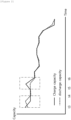
- FIG. 1 shows voltage values being monitored during battery charging and discharging and
- FIG. 2 shows capacity values being monitored during battery charging and discharging.
- a battery testing process may be performed in a manner in which a charge/discharge device repeatedly charges and discharges battery cells according to predetermined voltage and current conditions and measures electrical characteristics during the charge/discharge process.
- a state value of the battery is monitored to diagnose abnormalities such as whether ignition has occurred.
- a battery diagnosis apparatus provided in a battery system may be configured to monitor one or more state values such as battery voltage, battery surface temperature, and internal temperature of a container during a battery charging and discharging process.
- the battery diagnosis apparatus may determine that an abnormality has occurred in the battery when the voltage and temperature exceed preset thresholds or the difference between charge capacity and discharge capacity calculated through the battery state values exceeds a preset reference value.
- a charging and discharging test is performed while the battery is housed inside a container with a certain internal space. If the door of the container is opened or closed during the test, the state value monitored for diagnosis may change.
- the voltage value of the battery changes due to physical shock generated at the time of door opening (t1 and t2) when the door of the container is opened.
- the battery diagnosis apparatus may misdiagnose that a problem has occurred even though there is no problem with the battery, and thus, the reliability of the diagnosis result will be lowered.
- the present invention is intended to solve this problem.
- various embodiments of the present invention will be described in detail with reference to FIGS. 3 to 7 .
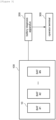
- FIG. 3 is a block diagram showing a battery system according to embodiments of the present invention.
- the battery system may include a plurality of batteries 10 (BAT #1 to BAT #N), a container 100 accommodating the plurality of batteries therein, a battery diagnosis apparatus 200, and an operator terminal 300.
- the battery system may further include a charging and discharging device (not shown) that is electrically connected to the plurality of batteries 10 and performs charging and discharging of the batteries.
- the battery system according to the present invention may correspond to a battery test system, but the scope of the present invention is not limited to this entity.
- the battery diagnosis apparatus 200 according to the present invention in addition to a battery test system for evaluating battery performance, may be applied to an energy storage system (ESS) and is configured to diagnose battery abnormalities during the battery charging and discharging process.
- ESS energy storage system
- the battery 10 according to the present invention may refer to a battery cell or a battery assembly.
- the battery diagnosis apparatus 200 may be configured to monitor at least one battery state value while the battery is being charged and discharged and diagnose whether there is an abnormality in the battery based on the battery state value.
- the battery state value may include one or more of voltage, current, surface temperature of the battery, and internal temperature of the container.
- the battery diagnosis apparatus 200 may generate a diagnostic result including one or more of a battery identifier, an abnormality type, and an abnormality occurrence time.
- the battery diagnosis apparatus 200 may output the generated diagnosis result to the operator terminal 300.
- the operator terminal 300 may correspond to a computing device managed by a manager or operator of the battery system.
- the operator terminal 300 may be configured to be connected to the battery diagnosis apparatus 200 through a wired or wireless network, receive a diagnosis result from the battery diagnosis apparatus 200, and output the diagnosis result through a display device.
- FIG. 4 shows a container according to embodiments of the present invention.
- the container 100 has a certain space inside to accommodate at least one battery and may be configured to include doors 111 and 112 that can be opened and closed.
- the container 100 shown in FIG. 4 includes left and right doors 111 and 112, but the scope of the present invention is not limited to the structure shown in FIG. 4 . In other words, it should be interpreted as a container according to the present invention as long as it is a container that includes a structure that can be opened and closed, regardless of the number, the shape, the coupling structure, or the name of the doors.
- the container 100 may further include a door lock 120 that controls whether the door is opened or closed.
- the door lock 120 may correspond to a digital door lock that includes an unlock button or a numeric input pad that can be input by an operator.
- the container 100 may be configured to include a detection sensor (not shown) capable of sensing open/closed state of the door.
- the detection sensor may be included inside the door lock 120 or may be fixedly coupled to a specific area of the doors 111 and 112.
- the battery diagnosis apparatus 200 may be connected with the detection sensor and receive state information of door from the detection sensor. Here, the battery diagnosis apparatus 200 may check whether the door is open or closed, open time, closing time, and a period of time being opened based on the received state information of door.
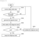
- FIG. 5 is an operational flowchart of a battery diagnosis method according to an embodiment of the present invention.
- the battery diagnosis apparatus 200 may monitor at least one battery state value during the charging and discharging process (S510).
- the battery state value may include one or more of voltage, current, surface temperature of the battery, and internal temperature of the container.
- the battery diagnosis apparatus 200 may diagnose whether there is an abnormality in the battery based on the battery state value (S520).
- the battery diagnosis apparatus 200 may generate a first diagnosis result (S530).
- the first diagnosis result may include one or more pieces of information among an identifier of the battery in which an abnormality occurred, a type of abnormality, and a time of abnormality occurrence.
- the battery diagnosis apparatus 200 may verify the validity of the first diagnosis result based on whether a door provided in the container 100 is opened or closed (S54 0) .
- the battery diagnosis apparatus 200 may check information about door status at the time the battery state value, which is the basis of the first diagnosis result, is collected.
- the battery diagnosis apparatus 200 may determine that the first diagnosis result is valid.
- the battery diagnosis apparatus 200 may determine that the first diagnosis result is invalid.
- the battery diagnosis apparatus 200 may output the first diagnosis result to the operator terminal 300 as the final diagnosis result (S560).
- the battery diagnosis apparatus 200 may invalidate the first diagnosis result (S570).
- the first diagnosis result may be treated as invalid and may not be output to the operator terminal 300.
- the validity of the diagnosis result is verified based on whether the door is open or closed and the final diagnosis result is output to the outside, thereby preventing misdiagnosis caused from data change or distortion due to the door opening.
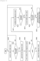
- FIG. 6 is an operational flowchart of a battery diagnosis method according to another embodiment of the present invention.
- the battery diagnosis apparatus 200 may monitor at least one battery state value during the charging and discharging process (S610).
- the battery diagnosis apparatus 200 may diagnose whether there is an abnormality in the battery based on the battery state value (S620).
- the battery diagnosis apparatus 200 may generate a first diagnosis result (S630).
- the first diagnosis result may include one or more pieces of information among an identifier of the battery in which an abnormality occurred, a type of abnormality, and a time of abnormality occurrence.
- the battery diagnosis apparatus 200 may verify the validity of the first diagnosis result based on whether a door provided in the container 100 is opened or closed (S640).
- the battery diagnosis apparatus 200 may output the first diagnosis result to the operator terminal 300 as the final diagnosis result (S660).
- the battery diagnosis apparatus 200 may invalidate the first diagnosis result (S671).
- the battery diagnosis apparatus 200 may correct the battery state value and re-diagnose whether the battery is abnormal based on the corrected battery state value.
- the battery diagnosis apparatus 200 may determine whether correction of the battery state value is possible based on an amount of change in the battery state value (S672).
- the battery diagnosis apparatus 200 may determine that correction is not possible if the amount of change in the battery state value exceeds a preset threshold value and may determine that correction is possible if the amount of change in the battery state value is equal to or less than the threshold value.
- a physical shock may be applied to the battery when a container door is opened, causing the voltage value of the battery to fluctuate.
- the amount of change in the voltage value or the slope in the voltage curve exceeds a preset threshold, it may be determined that re-diagnosis based on correction is not possible.
- the final diagnosis result may not be transmitted to the operator terminal 300 due to invalidation of the first diagnosis result and the battery diagnosis apparatus 200 may perform a battery monitoring process by returning to S610.
- the battery diagnosis apparatus 200 may correct the battery state value using the information about door status (S673).
- the battery diagnosis apparatus 200 may check the duration for which the container door is open and correct a battery state value, which is associated with internal temperature of the container, based on the duration for which the container door is open.
- the battery diagnosis apparatus 200 may correct a battery capacity value based on the relationship (Equation 1) between the duration for which the container door is open and the capacity change per unit time.
- d _ C k 1 * ln t + k 2 (Here, d_C is a capacity correction value, t is a temperature inside the container, and k1 and k2 are constants which are calculated experimentally)
- the battery capacity may be calculated based on the internal temperature of the container.
- the battery diagnosis apparatus 200 may correct the battery capacity value by calculating a capacity correction value based on the duration for which the door is open (maintaining time of open) and Equation 1 above and adding the calculated capacity correction value to the capacity value before correction.
- the battery diagnosis apparatus 200 may re-diagnose whether the battery is abnormal based on the battery state value which is corrected according to S673 (S674).
- the battery diagnosis apparatus 200 may generate a second diagnosis result and output the second diagnosis result to the operator terminal 300 as the final diagnosis result (S675).
- the second diagnosis result may include one or more information among an identifier of the battery in which an abnormality occurred, a type of abnormality, and a time of abnormality occurrence.
- the battery diagnosis apparatus 200 may return to S610 and perform a battery monitoring process.
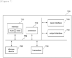
- FIG. 7 is a block diagram of a battery diagnosis apparatus according to embodiments of the present invention.
- the battery diagnosis apparatus 700 may be configured to be included in a battery system or a battery test system.
- the battery diagnosis apparatus may include at least one processor 710, a memory 720 that stores at least one instruction executed through the at least one processor, and a transceiver 730 that is connected to a network and performs communication.
- the at least one instruction may include an instruction to diagnose whether a battery is abnormal based on at least one battery state value during a process of charging and discharging the battery; an instruction to generate a first diagnosis result when an abnormality occurs in the battery; an instruction to verify validity of the first diagnosis result based on whether a door provided on a container accommodating the battery is opened or closed; and an instruction to output the first diagnosis result as a final diagnosis result in the instance that the first diagnosis result is determined to be valid.
- the instruction to verify validity of the first diagnosis result may include an instruction to check door status information at the time the at least one battery state value is collected; an instruction to determine the first diagnosis result as valid when it is confirmed that the door is in a closed state; and an instruction to determine that the first diagnosis result is invalid when it is confirmed that the door is in an open state.
- the at least one instruction may further include an instruction to invalidate the first diagnosis result in the instance that the first diagnosis result is determined to be invalid.
- the instruction to invalidate the first diagnosis result may include an instruction to correct the battery state value using the information on door status; and an instruction to re-diagnose whether the battery is abnormal based on the corrected battery state value.
- the instruction to re-diagnose whether the battery is abnormal may include an instruction to generate a second diagnosis result in the instance that it is determined that an abnormality has occurred in the battery as a result of re-diagnosis; and an instruction to output the second diagnosis result as a final diagnosis result.
- the instruction to correct the battery state value may include an instruction to determine a duration for which the door is open; and an instruction to correct a battery state value associated with internal temperature of the container based on the duration for which the door is open.
- the instruction to correct the battery state value may include an instruction to determine whether correction of the battery state value is possible based on an amount of change in the battery state value.
- the instruction to determine whether the correction of the battery state value is possible may include an instruction to determine that the correction of the battery state value is impossible in the instance that the amount of change in the battery state value exceeds a predetermined threshold.
- the battery diagnosis apparatus 700 may further include an input interface device 740, an output interface device 750, a storage device 760, etc. Respective components included in the battery diagnosis apparatus 700 may be connected by a bus 770 and can communicate with each other.
- the processor 710 may refer to a central processing unit (CPU), a graphics processing unit (GPU), or a dedicated processor on which methods according to embodiments of the present invention are performed.
- the memory (or storage device) may include at least one of a volatile storage medium and a non-volatile storage medium.
- the memory may include at least one of read only memory (ROM) and random access memory (RAM).
- the operations of the method according to the embodiments of the present invention may be implemented as a computer-readable program or code on a computer-readable recording medium.
- the computer-readable recording medium includes all types of recording devices in which data readable by a computer system is stored.
- the computer-readable recording medium may be distributed in a network-connected computer system to store and execute computer-readable programs or codes in a distributed manner.
- a block or apparatus corresponds to a method step or feature of a method step.
- aspects described in the context of a method may also represent a feature of a corresponding block or item or a corresponding apparatus.
- Some or all of the method steps may be performed by (or using) a hardware device, such as, for example, a microprocessor, a programmable computer, or an electronic circuit. In some embodiments, one or more of the most important method steps may be performed by such an apparatus.
Landscapes
- Physics & Mathematics (AREA)
- General Physics & Mathematics (AREA)
- Engineering & Computer Science (AREA)
- Manufacturing & Machinery (AREA)
- Chemical & Material Sciences (AREA)
- Chemical Kinetics & Catalysis (AREA)
- Electrochemistry (AREA)
- General Chemical & Material Sciences (AREA)
- Power Engineering (AREA)
- Charge And Discharge Circuits For Batteries Or The Like (AREA)
- Secondary Cells (AREA)
- Tests Of Electric Status Of Batteries (AREA)
Abstract
A battery diagnosis apparatus located within a battery system may include at least one processor; and a memory configured to store at least one instruction executed by the at least one processor.Here, the at least one instruction may include an instruction to diagnose whether a battery is abnormal based on at least one battery state value during a process of charging and discharging the battery; an instruction to generate a first diagnosis result when an abnormality occurs in the battery; an instruction to verify validity of the first diagnosis result based on whether a door provided on a container accommodating the battery is opened or closed; and an instruction to output the first diagnosis result as a final diagnosis result in the instance that the first diagnosis result is determined to be valid.
Description
- This application claims priority to and the benefit of
Korean Patent Application No.10-2023-0015396 filed in the Korean Intellectual Property Office on February 6, 2023 - The present invention relates to a battery diagnosis apparatus and method, and more particularly, to a battery diagnosis apparatus and method for preventing misdiagnosis due to opening and closing of a container including a battery.
- Secondary batteries, capable of recharging and reuse may be used as an energy source for small devices such as mobile phones, tablet PCs, and vacuum cleaners and may also be used as energy source for a medium-to-large devices, such as automobiles and an energy storage system (ESS) for smart grids.
- Secondary batteries may be used in the form of an assembly such as a battery module in which a plurality of battery cells is connected in series or parallel, or a battery pack in which a plurality of battery modules is connected in series or parallel, depending on the requirements of the system. In the case of medium-to-large devices such as electric vehicles, a high-capacity battery system with multiple battery packs connected in parallel may be applied to meet the required capacity of a corresponding device.
- Battery cells are manufactured through an assembly process and an activation process. Since battery cells are assembled in a discharged state, an activation process must be performed after the battery cell assembly process to activate positive electrode active material and create surface film (SEI: Solid Electrolyte Interface) on the negative electrode, so as to function as a battery. This activation process is called a formation process.
- The formation process may be performed in a manner in which a charging and discharging device repeatedly charges and discharges battery cells according to preset voltage and current conditions using an electrode probe. In addition, electrical characteristics may be measured during the charging and discharging process of the battery cells after the battery cells are mounted on the charging and discharging device used in the formation process, in order to test the performance of the battery cells.
- During the process of charging and discharging test of the battery, monitoring one or more state values of the battery is performed to diagnose abnormalities such as whether ignition has occurred. Here, in the instance that a door of a container in which the battery is accommodated opened, the state value of the battery may be distorted due to temperature change or physical shock, which may result in misdiagnosis.
- Thus, as a technical solution that can solve these problems of the prior art, an appropriate battery diagnosis technology is needed to prevent misdiagnosis due to opening and closing of a container in which the battery is accommodated.
- To obviate one or more problems of the related art, embodiments of the present disclosure provide a battery diagnosis apparatus that can prevent misdiagnosis due to opening and closing of a container in which a battery is accommodated.
- To obviate one or more problems of the related art, embodiments of the present disclosure also provide a battery diagnosing method performed by the battery diagnosis apparatus.
- To obviate one or more problems of the related art, embodiments of the present disclosure also provide a battery test system including the battery diagnosis apparatus.
- In order to achieve the objective of the present disclosure, a battery diagnosis apparatus located within a battery system may include at least one processor; and a memory configured to store at least one instruction executed by the at least one processor. Here, the at least one instruction may include an instruction to diagnose whether a battery is abnormal based on at least one battery state value during a process of charging and discharging the battery; an instruction to generate a first diagnosis result when an abnormality occurs in the battery; an instruction to verify validity of the first diagnosis result based on whether a door provided on a container accommodating the battery is opened or closed; and an instruction to output the first diagnosis result as a final diagnosis result in the instance that the first diagnosis result is determined to be valid.
- The instruction to verify validity of the first diagnosis result may include an instruction to check door status information at the time the at least one battery state value is collected; an instruction to determine the first diagnosis result as valid when it is confirmed that the door is in a closed state; and an instruction to determine that the first diagnosis result is invalid when it is confirmed that the door is in an open state.
- The at least one instruction may further include an instruction to invalidate the first diagnosis result in the instance that the first diagnosis result is determined to be invalid.
- The instruction to invalidate the first diagnosis result may include an instruction to correct the battery state value using the information on door status; and an instruction to re-diagnose whether the battery is abnormal based on the corrected battery state value.
- Here, the instruction to re-diagnose whether the battery is abnormal may include an instruction to generate a second diagnosis result in the instance that it is determined that an abnormality has occurred in the battery as a result of re-diagnosis; and an instruction to output the second diagnosis result as a final diagnosis result.
- The instruction to correct the battery state value may include an instruction to determine a duration for which the door is open; and an instruction to correct a battery state value associated with internal temperature of the container based on the duration for which the door is open.
- The instruction to correct the battery state value may include an instruction to determine whether correction of the battery state value is possible based on an amount of change in the battery state value.
- Here, the instruction to determine whether the correction of the battery state value is possible may include an instruction to determine that the correction of the battery state value is impossible in the instance that the amount of change in the battery state value exceeds a predetermined threshold.
- According to another embodiment of the present disclosure, a battery diagnosing method, performed by a battery diagnosis apparatus located within a battery system, may include diagnosing whether a battery is abnormal based on at least one battery state value during a process of charging and discharging the battery; generating a first diagnosis result in the instance that an abnormality occurs in the battery; verifying validity of the first diagnosis result based on whether a door provided on a container accommodating the battery is opened or closed; and outputting the first diagnosis result as a final diagnosis result in the instance that the first diagnosis result is determined to be valid.
- The verifying validity of the first diagnosis result may include checking information on door status at the time the at least one battery state value is collected; determining the first diagnosis result as valid in the instance that it is confirmed that the door is in a closed state; and determining that the first diagnosis result is invalid in the instance that it is confirmed that the door is in an open state.
- The method may further include invalidating the first diagnosis result in the instance that the first diagnosis result is determined to be invalid.
- The invalidating the first diagnosis result may include correcting the battery state value using the information on door status; and re-diagnosing whether the battery is abnormal based on the corrected battery state value.
- The re-diagnosing whether the battery is abnormal may include generating a second diagnosis result in the instance that it is determined that an abnormality has occurred in the battery as a result of re-diagnosis; and outputting the second diagnosis result as a final diagnosis result.
- The correcting the battery state value may include determining a duration for which the door is open; and correcting a battery state value associated with internal temperature of the container based on the duration for which the door is open.
- The correcting the battery state value may include determining whether correction of the battery state value is possible based on an amount of change in the battery state value.
- The determining whether the correction of the battery state value is possible may include determining that the correction of the battery state value is impossible in the instance that the amount of change in the battery state value exceeds a predetermined threshold.
- According to another embodiment of the present disclosure, a battery test system, configured to test a battery by charging and discharging the battery, may include a container which accommodates the battery and includes an openable door; and a battery diagnosis apparatus configured to diagnose whether a battery is abnormal based on at least one battery state value during a process of charging and discharging the battery. Here, the battery diagnosis apparatus may generate a first diagnosis result in the instance that an abnormality occurs in the battery, verify validity of the first diagnosis result based on whether a door provided on a container accommodating the battery is opened or closed, and output the first diagnosis result as a final diagnosis result in the instance that the first diagnosis result is determined to be valid.
- The battery diagnosis apparatus may further be configured to check information on door status at the time the at least one battery state value is collected; determine the first diagnosis result as valid in the instance that it is confirmed that the door is in a closed state; and determine that the first diagnosis result is invalid in the instance that it is confirmed that the door is in an open state.
- The battery diagnosis apparatus may further be configured to invalidate the first diagnosis result in the instance that the first diagnosis result is determined to be invalid.
- The battery diagnosis apparatus may further be configured to correct the battery state value using the information on door status and to re-diagnose whether the battery is abnormal based on the corrected battery state value.
- Here, the battery diagnosis apparatus may further be configured to generate a second diagnosis result in the instance that it is determined that an abnormality has occurred in the battery as a result of re-diagnosis and to output the second diagnosis result as a final diagnosis result.
- The battery diagnosis apparatus may further be configured to determine a duration for which the door is open and to correct a battery state value associated with internal temperature of the container based on the duration for which the door is open.
- The battery diagnosis apparatus may further be configured to determine whether correction of the battery state value is possible based on an amount of change in the battery state value.
- Here, the battery diagnosis apparatus may further be configured to determine that the correction of the battery state value is impossible in the instance that the amount of change in the battery state value exceeds a predetermined threshold.
- According to embodiments of the present disclosure, the accuracy of battery abnormality diagnosis can be significantly improved through outputting a final diagnostic result by verifying the validity of a diagnostic result based on whether the container is opened or closed.
-
-
FIG. 1 shows voltage values being monitored during battery charging and discharging. -
FIG. 2 shows capacity values being monitored during battery charging and discharging. -
FIG. 3 is a block diagram showing a battery system according to embodiments of the present invention. -
FIG. 4 shows a container according to embodiments of the present invention. -
FIG. 5 is an operational flowchart of a battery diagnosis method according to an embodiment of the present invention. -
FIG. 6 is an operational flowchart of a battery diagnosis method according to another embodiment of the present invention. -
FIG. 7 is a block diagram of a battery diagnosis apparatus according to embodiments of the present invention. - 10: battery
- 100: container
- 111, 112: door
- 120: door lock
- 200, 700: battery diagnosis apparatus
- 300: operator terminal
- The present invention may be modified in various forms and have various embodiments, and specific embodiments thereof are shown by way of example in the drawings and will be described in detail below. It should be understood, however, that there is no intent to limit the present invention to the specific embodiments, but on the contrary, the present invention is to cover all modifications, equivalents, and alternatives falling within the spirit and technical scope of the present invention. Like reference numerals refer to like elements throughout the description of the figures.
- It will be understood that, although the terms such as first, second, A, B, and the like may be used herein to describe various elements, these elements should not be limited by these terms. These terms are only used to distinguish one element from another. For example, a first element could be termed a second element, and, similarly, a second element could be termed a first element, without departing from the scope of the present invention. As used herein, the term "and/or" includes combinations of a plurality of associated listed items or any of the plurality of associated listed items.
- It will be understood that when an element is referred to as being "coupled" or "connected" to another element, it can be directly coupled or connected to the other element or an intervening element may be present. In contrast, when an element is referred to as being "directly coupled" or "directly connected" to another element, there is no intervening element present.
- The terms used herein is for the purpose of describing specific embodiments only and are not intended to limit the present invention. As used herein, the singular forms "a", "an" and "the" are intended to include the plural forms as well, unless the context clearly indicates otherwise. It will be further understood that the terms "comprises", "comprising", "includes", "including" and/or "having", when used herein, specify the presence of stated features, integers, steps, operations, constitutional elements, components and/or combinations thereof, but do not preclude the presence or addition of one or more other features, integers, steps, operations, constitutional elements, components, and/or combinations thereof.
- Unless otherwise defined, all terms used herein, including technical and scientific terms, have the same meanings as commonly understood by one skilled in the art to which the present invention belongs. It will be further understood that terms, such as those defined in commonly used dictionaries, should be interpreted as having meanings that are consistent with their meanings in the context of the relevant art and will not be interpreted in an idealized or overly formal sense unless expressly so defined herein.
- Some terms used herein are defined as follows.
- State of charge (SOC) refers to a current charged state of a battery, represented in percent points [%]. Meanwhile, state of health (SOH) may be an indicator of current state as to degree of battery aging, represented in percent points [%].
- A battery cell is a minimum unit that serves to store power and a battery module refers to an assembly in which a plurality of battery cells is electrically connected.
- A battery pack or battery rack refers to a system of a single structure which is assembled by electrically connecting module units, set by a battery manufacturer, and can be monitored and controlled by a battery management apparatus/system (BMS). A battery pack or battery rack may include several battery modules and a battery protection unit or any other protection device.
- A battery bank refers to a group of large-scale battery rack systems configured by connecting a plurality of racks in parallel. A bank BMS for a battery bank may monitor and control rack BMSs, each of which manages a battery rack.
- A battery assembly may include a plurality of electrically connected battery cells, and refers to an assembly that functions as a power supply source by being applied to a specific system or device. Here, the battery assembly may mean a battery module, a battery pack, a battery rack, or a battery bank, but the scope of the present invention is not limited to these entities.
- Hereinafter, exemplary embodiments of the present invention will be described in detail with reference to the accompanying drawings.
-
FIG. 1 shows voltage values being monitored during battery charging and discharging andFIG. 2 shows capacity values being monitored during battery charging and discharging. - A battery testing process may be performed in a manner in which a charge/discharge device repeatedly charges and discharges battery cells according to predetermined voltage and current conditions and measures electrical characteristics during the charge/discharge process.
- Generally, in order to ensure safety of a battery test system when conducting a battery charge/discharge test, a state value of the battery is monitored to diagnose abnormalities such as whether ignition has occurred.
- For example, a battery diagnosis apparatus provided in a battery system may be configured to monitor one or more state values such as battery voltage, battery surface temperature, and internal temperature of a container during a battery charging and discharging process. Here, the battery diagnosis apparatus may determine that an abnormality has occurred in the battery when the voltage and temperature exceed preset thresholds or the difference between charge capacity and discharge capacity calculated through the battery state values exceeds a preset reference value.
- Meanwhile, a charging and discharging test is performed while the battery is housed inside a container with a certain internal space. If the door of the container is opened or closed during the test, the state value monitored for diagnosis may change.
- Referring to (A) and (B) in
FIG. 1 , it can be understood that the voltage value of the battery changes due to physical shock generated at the time of door opening (t1 and t2) when the door of the container is opened. - In addition, referring to
FIG. 2 , when the door of the container is opened and closed, outside air flows in during the time period (t3 to t4, t5 to t6) for which the door is open and then closed and the internal temperature value of the container may fluctuate, thereby the calculated charging capacity and discharging capacity varying accordingly. - As described above, if the battery state value changes or is distorted due to the opening and closing of the container door, the battery diagnosis apparatus may misdiagnose that a problem has occurred even though there is no problem with the battery, and thus, the reliability of the diagnosis result will be lowered.
- The present invention is intended to solve this problem. Hereinafter, various embodiments of the present invention will be described in detail with reference to
FIGS. 3 to 7 . -
FIG. 3 is a block diagram showing a battery system according to embodiments of the present invention. - Referring to
FIG. 3 , the battery system may include a plurality of batteries 10 (BAT # 1 to BAT #N), acontainer 100 accommodating the plurality of batteries therein, abattery diagnosis apparatus 200, and anoperator terminal 300. In addition, the battery system may further include a charging and discharging device (not shown) that is electrically connected to the plurality ofbatteries 10 and performs charging and discharging of the batteries. - In embodiments, the battery system according to the present invention may correspond to a battery test system, but the scope of the present invention is not limited to this entity. For example, the
battery diagnosis apparatus 200 according to the present invention, in addition to a battery test system for evaluating battery performance, may be applied to an energy storage system (ESS) and is configured to diagnose battery abnormalities during the battery charging and discharging process. - The
battery 10 according to the present invention may refer to a battery cell or a battery assembly. - The
battery diagnosis apparatus 200 may be configured to monitor at least one battery state value while the battery is being charged and discharged and diagnose whether there is an abnormality in the battery based on the battery state value. Here, the battery state value may include one or more of voltage, current, surface temperature of the battery, and internal temperature of the container. - When it is determined that an abnormality has occurred in the battery, the
battery diagnosis apparatus 200 may generate a diagnostic result including one or more of a battery identifier, an abnormality type, and an abnormality occurrence time. Here, thebattery diagnosis apparatus 200 may output the generated diagnosis result to theoperator terminal 300. - The
operator terminal 300 may correspond to a computing device managed by a manager or operator of the battery system. Theoperator terminal 300 may be configured to be connected to thebattery diagnosis apparatus 200 through a wired or wireless network, receive a diagnosis result from thebattery diagnosis apparatus 200, and output the diagnosis result through a display device. -
FIG. 4 shows a container according to embodiments of the present invention. - Referring to
FIG. 4 , thecontainer 100 has a certain space inside to accommodate at least one battery and may be configured to includedoors - The
container 100 shown inFIG. 4 includes left andright doors FIG. 4 . In other words, it should be interpreted as a container according to the present invention as long as it is a container that includes a structure that can be opened and closed, regardless of the number, the shape, the coupling structure, or the name of the doors. - In an embodiment, the
container 100 may further include adoor lock 120 that controls whether the door is opened or closed. For example, thedoor lock 120 may correspond to a digital door lock that includes an unlock button or a numeric input pad that can be input by an operator. - The
container 100 may be configured to include a detection sensor (not shown) capable of sensing open/closed state of the door. Here, the detection sensor may be included inside thedoor lock 120 or may be fixedly coupled to a specific area of thedoors - The
battery diagnosis apparatus 200 may be connected with the detection sensor and receive state information of door from the detection sensor. Here, thebattery diagnosis apparatus 200 may check whether the door is open or closed, open time, closing time, and a period of time being opened based on the received state information of door. -
FIG. 5 is an operational flowchart of a battery diagnosis method according to an embodiment of the present invention. - When charging and discharging of the battery begins, the
battery diagnosis apparatus 200 may monitor at least one battery state value during the charging and discharging process (S510). Here, the battery state value may include one or more of voltage, current, surface temperature of the battery, and internal temperature of the container. - Thereafter, the
battery diagnosis apparatus 200 may diagnose whether there is an abnormality in the battery based on the battery state value (S520). - If it is determined that an abnormality has occurred in the battery as a result of the diagnosis (YES in S520), the
battery diagnosis apparatus 200 may generate a first diagnosis result (S530). Here, the first diagnosis result may include one or more pieces of information among an identifier of the battery in which an abnormality occurred, a type of abnormality, and a time of abnormality occurrence. - Thereafter, the
battery diagnosis apparatus 200 may verify the validity of the first diagnosis result based on whether a door provided in thecontainer 100 is opened or closed (S54 0) . - More specifically, when a first diagnosis result is generated due to a battery abnormality, the
battery diagnosis apparatus 200 may check information about door status at the time the battery state value, which is the basis of the first diagnosis result, is collected. Here, when it is assured that the door is in a closed state, thebattery diagnosis apparatus 200 may determine that the first diagnosis result is valid. In addition, when it is assured that the door is open, thebattery diagnosis apparatus 200 may determine that the first diagnosis result is invalid. - If the first diagnosis result is determined to be valid (YES in S550), the
battery diagnosis apparatus 200 may output the first diagnosis result to theoperator terminal 300 as the final diagnosis result (S560). - If the first diagnosis result is determined to be invalid (NO in S550), the
battery diagnosis apparatus 200 may invalidate the first diagnosis result (S570). In other words, in the instance that the first diagnosis result is generated based on the battery state value measured while the door of the container is open, the first diagnosis result may be treated as invalid and may not be output to theoperator terminal 300. - According to the embodiment of the present invention as described above, the validity of the diagnosis result is verified based on whether the door is open or closed and the final diagnosis result is output to the outside, thereby preventing misdiagnosis caused from data change or distortion due to the door opening.
-
FIG. 6 is an operational flowchart of a battery diagnosis method according to another embodiment of the present invention. - When charging and discharging of the battery begins, the
battery diagnosis apparatus 200 may monitor at least one battery state value during the charging and discharging process (S610). - Thereafter, the
battery diagnosis apparatus 200 may diagnose whether there is an abnormality in the battery based on the battery state value (S620). - If it is determined that an abnormality has occurred in the battery as a result of the diagnosis (YES in S620), the
battery diagnosis apparatus 200 may generate a first diagnosis result (S630). Here, the first diagnosis result may include one or more pieces of information among an identifier of the battery in which an abnormality occurred, a type of abnormality, and a time of abnormality occurrence. - Thereafter, the
battery diagnosis apparatus 200 may verify the validity of the first diagnosis result based on whether a door provided in thecontainer 100 is opened or closed (S640). - If the first diagnosis result is determined to be valid (YES in S650), the
battery diagnosis apparatus 200 may output the first diagnosis result to theoperator terminal 300 as the final diagnosis result (S660). - If the first diagnosis result is determined to be invalid (NO in S650), the
battery diagnosis apparatus 200 may invalidate the first diagnosis result (S671). - After invalidating the first diagnosis result, the
battery diagnosis apparatus 200 may correct the battery state value and re-diagnose whether the battery is abnormal based on the corrected battery state value. - In an embodiment, the
battery diagnosis apparatus 200 may determine whether correction of the battery state value is possible based on an amount of change in the battery state value (S672). Here, thebattery diagnosis apparatus 200 may determine that correction is not possible if the amount of change in the battery state value exceeds a preset threshold value and may determine that correction is possible if the amount of change in the battery state value is equal to or less than the threshold value. - For example, a physical shock may be applied to the battery when a container door is opened, causing the voltage value of the battery to fluctuate. Here, if the amount of change in the voltage value or the slope in the voltage curve exceeds a preset threshold, it may be determined that re-diagnosis based on correction is not possible.
- If it is determined that correction of the battery state value is impossible (NO in S672), the final diagnosis result may not be transmitted to the
operator terminal 300 due to invalidation of the first diagnosis result and thebattery diagnosis apparatus 200 may perform a battery monitoring process by returning to S610. - If it is determined that correction of the battery state value is possible (YES in S672), the
battery diagnosis apparatus 200 may correct the battery state value using the information about door status (S673). Here, thebattery diagnosis apparatus 200 may check the duration for which the container door is open and correct a battery state value, which is associated with internal temperature of the container, based on the duration for which the container door is open. - In an embodiment, the
battery diagnosis apparatus 200 may correct a battery capacity value based on the relationship (Equation 1) between the duration for which the container door is open and the capacity change per unit time.
- In more specific, the battery capacity may be calculated based on the internal temperature of the container. When the container door is opened, outside air flows in and the internal temperature value of the container changes, resulting in a capacity value different from the actual capacity value. Here, the
battery diagnosis apparatus 200 may correct the battery capacity value by calculating a capacity correction value based on the duration for which the door is open (maintaining time of open) andEquation 1 above and adding the calculated capacity correction value to the capacity value before correction. - For example, when k1 is defined as 0.0047 and k2 as 0.0148, the temperature before opening the door is 10 degrees, the temperature just before closing after opening the door is 15 degrees, and the duration for which the container door is open is 60 seconds, the capacity correction value may be calculated as follows.
d_C = {(0.0047*ln(10) + 0.0148) - (0.0047*ln(15) + 0.0148)} * 60 - Thereafter, the
battery diagnosis apparatus 200 may re-diagnose whether the battery is abnormal based on the battery state value which is corrected according to S673 (S674). - When it is determined that an abnormality has occurred in the battery as a result of the re-diagnosis, (YES in S674), the
battery diagnosis apparatus 200 may generate a second diagnosis result and output the second diagnosis result to theoperator terminal 300 as the final diagnosis result (S675). Here, the second diagnosis result may include one or more information among an identifier of the battery in which an abnormality occurred, a type of abnormality, and a time of abnormality occurrence. - When it is determined that no problem has occurred in the battery as a result of the re-diagnosis (NO in S674), the first diagnosis result is invalidated and the final diagnosis result is not transmitted to the
operator terminal 300 according to the re-diagnosis result (no abnormality). Furthermore, thebattery diagnosis apparatus 200 may return to S610 and perform a battery monitoring process. -
FIG. 7 is a block diagram of a battery diagnosis apparatus according to embodiments of the present invention. - The
battery diagnosis apparatus 700 according to embodiments of the present invention may be configured to be included in a battery system or a battery test system. The battery diagnosis apparatus may include at least oneprocessor 710, amemory 720 that stores at least one instruction executed through the at least one processor, and atransceiver 730 that is connected to a network and performs communication. - The at least one instruction may include an instruction to diagnose whether a battery is abnormal based on at least one battery state value during a process of charging and discharging the battery; an instruction to generate a first diagnosis result when an abnormality occurs in the battery; an instruction to verify validity of the first diagnosis result based on whether a door provided on a container accommodating the battery is opened or closed; and an instruction to output the first diagnosis result as a final diagnosis result in the instance that the first diagnosis result is determined to be valid.
- The instruction to verify validity of the first diagnosis result may include an instruction to check door status information at the time the at least one battery state value is collected; an instruction to determine the first diagnosis result as valid when it is confirmed that the door is in a closed state; and an instruction to determine that the first diagnosis result is invalid when it is confirmed that the door is in an open state.
- The at least one instruction may further include an instruction to invalidate the first diagnosis result in the instance that the first diagnosis result is determined to be invalid.
- The instruction to invalidate the first diagnosis result may include an instruction to correct the battery state value using the information on door status; and an instruction to re-diagnose whether the battery is abnormal based on the corrected battery state value.
- Here, the instruction to re-diagnose whether the battery is abnormal may include an instruction to generate a second diagnosis result in the instance that it is determined that an abnormality has occurred in the battery as a result of re-diagnosis; and an instruction to output the second diagnosis result as a final diagnosis result.
- The instruction to correct the battery state value may include an instruction to determine a duration for which the door is open; and an instruction to correct a battery state value associated with internal temperature of the container based on the duration for which the door is open.
- The instruction to correct the battery state value may include an instruction to determine whether correction of the battery state value is possible based on an amount of change in the battery state value.
- Here, the instruction to determine whether the correction of the battery state value is possible may include an instruction to determine that the correction of the battery state value is impossible in the instance that the amount of change in the battery state value exceeds a predetermined threshold.
- The
battery diagnosis apparatus 700 may further include aninput interface device 740, anoutput interface device 750, astorage device 760, etc. Respective components included in thebattery diagnosis apparatus 700 may be connected by abus 770 and can communicate with each other. - Here, the
processor 710 may refer to a central processing unit (CPU), a graphics processing unit (GPU), or a dedicated processor on which methods according to embodiments of the present invention are performed. Additionally, the memory (or storage device) may include at least one of a volatile storage medium and a non-volatile storage medium. For example, the memory may include at least one of read only memory (ROM) and random access memory (RAM). - The operations of the method according to the embodiments of the present invention may be implemented as a computer-readable program or code on a computer-readable recording medium. The computer-readable recording medium includes all types of recording devices in which data readable by a computer system is stored. In addition, the computer-readable recording medium may be distributed in a network-connected computer system to store and execute computer-readable programs or codes in a distributed manner.
- Although some aspects of the invention have been described in the context of the apparatus, it may also represent a description according to a corresponding method, wherein a block or apparatus corresponds to a method step or feature of a method step. Similarly, aspects described in the context of a method may also represent a feature of a corresponding block or item or a corresponding apparatus. Some or all of the method steps may be performed by (or using) a hardware device, such as, for example, a microprocessor, a programmable computer, or an electronic circuit. In some embodiments, one or more of the most important method steps may be performed by such an apparatus.
- In the forgoing, the present invention has been described with reference to the exemplary embodiment of the present invention, but those skilled in the art may appreciate that the present invention may be variously corrected and changed within the range without departing from the spirit and the area of the present invention described in the appending claims.
Claims (24)
- A battery diagnosis apparatus located within a battery system, the apparatus comprising:at least one processor; anda memory configured to store at least one instruction executed by the at least one processor,wherein the at least one instruction includes:an instruction to diagnose whether a battery is abnormal based on at least one battery state value during a process of charging and discharging the battery;an instruction to generate a first diagnosis result in the instance that an abnormality occurs in the battery;an instruction to verify validity of the first diagnosis result based on whether a door provided on a container accommodating the battery is opened or closed; andan instruction to output the first diagnosis result as a final diagnosis result in the instance that the first diagnosis result is determined to be valid.
- The battery diagnosis apparatus of claim 1, wherein the instruction to verify validity of the first diagnosis result includes:an instruction to check information on door status at the time the at least one battery state value is collected;an instruction to determine the first diagnosis result as valid in the instance that it is confirmed that the door is in a closed state; andan instruction to determine that the first diagnosis result is invalid in the instance that it is confirmed that the door is in an open state.
- The battery diagnosis apparatus of claim 1, wherein the at least one instruction further includes an instruction to invalidate the first diagnosis result in the instance that the first diagnosis result is determined to be invalid.
- The battery diagnosis apparatus of claim 3, wherein the instruction to invalidate the first diagnosis result includes:an instruction to correct the battery state value using the information on door status; andan instruction to re-diagnose whether the battery is abnormal based on the corrected battery state value.
- The battery diagnosis apparatus of claim 4, wherein the instruction to re-diagnose whether the battery is abnormal includes:an instruction to generate a second diagnosis result in the instance that it is determined that an abnormality has occurred in the battery as a result of re-diagnosis; andan instruction to output the second diagnosis result as a final diagnosis result.
- The battery diagnosis apparatus of claim 4, wherein the instruction to correct the battery state value includes:an instruction to determine a duration for which the door is open; andan instruction to correct a battery state value associated with internal temperature of the container based on the duration for which the door is open.
- The battery diagnosis apparatus of claim 4, wherein the instruction to correct the battery state value includes an instruction to determine whether correction of the battery state value is possible based on an amount of change in the battery state value.
- The battery diagnosis apparatus of claim 7, wherein the instruction to determine whether the correction of the battery state value is possible includes an instruction to determine that the correction of the battery state value is impossible in the instance that the amount of change in the battery state value exceeds a predetermined threshold.
- A battery diagnosing method performed by a battery diagnosis apparatus located within a battery system, the battery diagnosing method comprising:diagnosing whether a battery is abnormal based on at least one battery state value during a process of charging and discharging the battery;generating a first diagnosis result in the instance that an abnormality occurs in the battery;verifying validity of the first diagnosis result based on whether a door provided on a container accommodating the battery is opened or closed; andoutputting the first diagnosis result as a final diagnosis result in the instance that the first diagnosis result is determined to be valid.
- The battery diagnosing method of claim 9, wherein the verifying validity of the first diagnosis result includes:checking information on door status at the time the at least one battery state value is collected;determining the first diagnosis result as valid in the instance that it is confirmed that the door is in a closed state; anddetermining that the first diagnosis result is invalid in the instance that it is confirmed that the door is in an open state.
- The battery diagnosing method of claim 9, further comprising invalidating the first diagnosis result in the instance that the first diagnosis result is determined to be invalid.
- The battery diagnosing method of claim 11, wherein the invalidating the first diagnosis result includes:correcting the battery state value using the information on door status; andre-diagnosing whether the battery is abnormal based on the corrected battery state value.
- The battery diagnosing method of claim 12, wherein the re-diagnosing whether the battery is abnormal includes:generating a second diagnosis result in the instance that it is determined that an abnormality has occurred in the battery as a result of re-diagnosis; andoutputting the second diagnosis result as a final diagnosis result.
- The battery diagnosing method of claim 12, wherein the correcting the battery state value includes:determining a duration for which the door is open; andcorrecting a battery state value associated with internal temperature of the container based on the duration for which the door is open.
- The battery diagnosing method of claim 12, wherein the correcting the battery state value includes determining whether correction of the battery state value is possible based on an amount of change in the battery state value.
- The battery diagnosing method of claim 15, wherein the determining whether the correction of the battery state value is possible includes determining that the correction of the battery state value is impossible in the instance that the amount of change in the battery state value exceeds a predetermined threshold.
- A battery test system configured to test a battery by charging and discharging the battery, the battery test system comprising:a container which accommodates the battery and includes an openable door; anda battery diagnosis apparatus configured to diagnose whether a battery is abnormal based on at least one battery state value during a process of charging and discharging the battery,wherein the battery diagnosis apparatus generates a first diagnosis result in the instance that an abnormality occurs in the battery, verifies validity of the first diagnosis result based on whether the door provided on the container accommodating the battery is opened or closed, and outputs the first diagnosis result as a final diagnosis result in the instance that the first diagnosis result is determined to be valid.
- The battery test system of claim 17, wherein the battery diagnosis apparatus is further configured to:check information on door status at the time the at least one battery state value is collected;determine the first diagnosis result as valid in the instance that it is confirmed that the door is in a closed state; anddetermine that the first diagnosis result is invalid in the instance that it is confirmed that the door is in an open state.
- The battery test system of claim 17, wherein the battery diagnosis apparatus is further configured to invalidate the first diagnosis result in the instance that the first diagnosis result is determined to be invalid.
- The battery test system of claim 19, wherein the battery diagnosis apparatus is further configured to correct the battery state value using the information on door status and to re-diagnose whether the battery is abnormal based on the corrected battery state value.
- The battery test system of claim 20, wherein the battery diagnosis apparatus is further configured to generate a second diagnosis result in the instance that it is determined that an abnormality has occurred in the battery as a result of re-diagnosis and to output the second diagnosis result as a final diagnosis result.
- The battery test system of claim 20, wherein the battery diagnosis apparatus is further configured to determine a duration for which the door is open and to correct a battery state value associated with internal temperature of the container based on the duration for which the door is open.
- The battery test system of claim 20, wherein the battery diagnosis apparatus is further configured to determine whether correction of the battery state value is possible based on an amount of change in the battery state value.
- The battery test system of claim 23, wherein the battery diagnosis apparatus is further configured to determine that the correction of the battery state value is impossible in the instance that the amount of change in the battery state value exceeds a predetermined threshold.
Applications Claiming Priority (2)
| Application Number | Priority Date | Filing Date | Title |
|---|---|---|---|
| KR1020230015396A KR20240122986A (en) | 2023-02-06 | 2023-02-06 | Battery diagnosis apparatus and method |
| PCT/KR2023/019589 WO2024167115A1 (en) | 2023-02-06 | 2023-11-30 | Battery diagnostic device and method |
Publications (1)
| Publication Number | Publication Date |
|---|---|
| EP4513211A1 true EP4513211A1 (en) | 2025-02-26 |
Family
ID=92263153
Family Applications (1)
| Application Number | Title | Priority Date | Filing Date |
|---|---|---|---|
| EP23921488.5A Pending EP4513211A1 (en) | 2023-02-06 | 2023-11-30 | Battery diagnostic device and method |
Country Status (6)
| Country | Link |
|---|---|
| US (1) | US20250327866A1 (en) |
| EP (1) | EP4513211A1 (en) |
| JP (1) | JP2025517461A (en) |
| KR (1) | KR20240122986A (en) |
| CN (1) | CN119404106A (en) |
| WO (1) | WO2024167115A1 (en) |
Family Cites Families (9)
| Publication number | Priority date | Publication date | Assignee | Title |
|---|---|---|---|---|
| JPS5832450U (en) | 1981-08-26 | 1983-03-03 | 日本精機株式会社 | pressure detector |
| US6885307B2 (en) * | 2002-06-19 | 2005-04-26 | Tarma, Llc | Battery monitor |
| KR100669475B1 (en) * | 2005-12-21 | 2007-01-16 | 삼성에스디아이 주식회사 | SOC calibration method of battery and battery management system using same |
| JP2014163921A (en) * | 2013-02-28 | 2014-09-08 | Fujitsu Telecom Networks Ltd | Charging/discharging test system and control device |
| KR101751011B1 (en) * | 2014-09-19 | 2017-06-26 | 주식회사 엘지화학 | Test Device for Battery Cell |
| KR102227308B1 (en) * | 2017-05-02 | 2021-03-15 | 주식회사 엘지화학 | Charging and discharging device and method of battery cell |
| KR102827897B1 (en) * | 2019-05-28 | 2025-07-01 | 주식회사 엘지에너지솔루션 | Bms and method for sending data to upper system |
| KR102332444B1 (en) * | 2019-12-23 | 2021-11-26 | 삼성에스디아이 주식회사 | Thermal runaway detection device, battery system and thermal runaway detection method thereof |
| JP7584621B2 (en) | 2020-07-22 | 2024-11-15 | ワッカー ケミー アクチエンゲゼルシャフト | Alkyl Silicate |
-
2023
- 2023-02-06 KR KR1020230015396A patent/KR20240122986A/en active Pending
- 2023-11-30 US US18/868,480 patent/US20250327866A1/en active Pending
- 2023-11-30 WO PCT/KR2023/019589 patent/WO2024167115A1/en not_active Ceased
- 2023-11-30 CN CN202380048391.1A patent/CN119404106A/en active Pending
- 2023-11-30 EP EP23921488.5A patent/EP4513211A1/en active Pending
- 2023-11-30 JP JP2024569088A patent/JP2025517461A/en active Pending
Also Published As
| Publication number | Publication date |
|---|---|
| CN119404106A (en) | 2025-02-07 |
| KR20240122986A (en) | 2024-08-13 |
| JP2025517461A (en) | 2025-06-05 |
| US20250327866A1 (en) | 2025-10-23 |
| WO2024167115A1 (en) | 2024-08-15 |
Similar Documents
| Publication | Publication Date | Title |
|---|---|---|
| CN114514433B (en) | Device and method for diagnosing a battery | |
| US20240003980A1 (en) | Battery management apparatus and method | |
| US20230258725A1 (en) | Battery abnormality diagnosis apparatus and method | |
| US12253572B2 (en) | Battery diagnosing apparatus and method | |
| GB2547502A (en) | Detection of false reporting in a smart battery system | |
| CN121069202A (en) | Battery system diagnosis apparatus and method | |
| EP4462141A1 (en) | Faulty battery detection apparatus and method | |
| EP4016099A1 (en) | Battery diagnostic apparatus and method | |
| US20250327866A1 (en) | Battery Diagnostic Device and Method | |
| KR20230095556A (en) | Apparatus for estimating state of health of battery and operating method of the same | |
| EP4675291A1 (en) | Battery management device and operating method thereof | |
| US12235322B2 (en) | Battery diagnosis apparatus and method for leakage current detection | |
| EP4647789A1 (en) | Battery management device and server, and battery system comprising same | |
| ES3055054T3 (en) | Battery data management apparatus and operating method thereof | |
| EP4628916A1 (en) | Battery diagnosis device and method | |
| KR102920007B1 (en) | Apparatus for managing battery and operating method of the same | |
| EP4707836A1 (en) | Battery management apparatus and operating method thereof | |
| EP4726420A1 (en) | Battery management apparatus and operating method thereof | |
| KR102966905B1 (en) | Apparatus for managing battery and operating method of the same | |
| EP4682562A2 (en) | Battery diagnosis apparatus and operation method thereof | |
| KR20260047885A (en) | Battery diagnosis apparatus and method | |
| KR20240162236A (en) | Apparatus for managing battery and operating method of the same | |
| JP2026515041A (en) | Battery management device and its operating method | |
| CN118265919A (en) | Battery diagnostic device and method for detecting leakage current | |
| CN121464366A (en) | Battery diagnosis device and method |
Legal Events
| Date | Code | Title | Description |
|---|---|---|---|
| STAA | Information on the status of an ep patent application or granted ep patent |
Free format text: STATUS: THE INTERNATIONAL PUBLICATION HAS BEEN MADE |
|
| PUAI | Public reference made under article 153(3) epc to a published international application that has entered the european phase |
Free format text: ORIGINAL CODE: 0009012 |
|
| STAA | Information on the status of an ep patent application or granted ep patent |
Free format text: STATUS: REQUEST FOR EXAMINATION WAS MADE |
|
| 17P | Request for examination filed |
Effective date: 20241119 |
|
| AK | Designated contracting states |
Kind code of ref document: A1 Designated state(s): AL AT BE BG CH CY CZ DE DK EE ES FI FR GB GR HR HU IE IS IT LI LT LU LV MC ME MK MT NL NO PL PT RO RS SE SI SK SM TR |
|
| DAV | Request for validation of the european patent (deleted) | ||
| DAX | Request for extension of the european patent (deleted) |