EP4513170A1 - Nucleoside phosphoroamidite identification system, and nucleoside phosphoroamidite identification method and program - Google Patents
Nucleoside phosphoroamidite identification system, and nucleoside phosphoroamidite identification method and program Download PDFInfo
- Publication number
- EP4513170A1 EP4513170A1 EP23791738.0A EP23791738A EP4513170A1 EP 4513170 A1 EP4513170 A1 EP 4513170A1 EP 23791738 A EP23791738 A EP 23791738A EP 4513170 A1 EP4513170 A1 EP 4513170A1
- Authority
- EP
- European Patent Office
- Prior art keywords
- nucleoside phosphoramidite
- nucleoside
- identifying
- unit
- spectrum
- Prior art date
- Legal status (The legal status is an assumption and is not a legal conclusion. Google has not performed a legal analysis and makes no representation as to the accuracy of the status listed.)
- Pending
Links
Images






Classifications
-
- G—PHYSICS
- G01—MEASURING; TESTING
- G01N—INVESTIGATING OR ANALYSING MATERIALS BY DETERMINING THEIR CHEMICAL OR PHYSICAL PROPERTIES
- G01N21/00—Investigating or analysing materials by the use of optical means, i.e. using sub-millimetre waves, infrared, visible or ultraviolet light
- G01N21/17—Systems in which incident light is modified in accordance with the properties of the material investigated
- G01N21/25—Colour; Spectral properties, i.e. comparison of effect of material on the light at two or more different wavelengths or wavelength bands
- G01N21/31—Investigating relative effect of material at wavelengths characteristic of specific elements or molecules, e.g. atomic absorption spectrometry
- G01N21/35—Investigating relative effect of material at wavelengths characteristic of specific elements or molecules, e.g. atomic absorption spectrometry using infrared light
- G01N21/3577—Investigating relative effect of material at wavelengths characteristic of specific elements or molecules, e.g. atomic absorption spectrometry using infrared light for analysing liquids, e.g. polluted water
-
- G—PHYSICS
- G01—MEASURING; TESTING
- G01N—INVESTIGATING OR ANALYSING MATERIALS BY DETERMINING THEIR CHEMICAL OR PHYSICAL PROPERTIES
- G01N21/00—Investigating or analysing materials by the use of optical means, i.e. using sub-millimetre waves, infrared, visible or ultraviolet light
- G01N21/62—Systems in which the material investigated is excited whereby it emits light or causes a change in wavelength of the incident light
- G01N21/63—Systems in which the material investigated is excited whereby it emits light or causes a change in wavelength of the incident light optically excited
- G01N21/65—Raman scattering
-
- G—PHYSICS
- G16—INFORMATION AND COMMUNICATION TECHNOLOGY [ICT] SPECIALLY ADAPTED FOR SPECIFIC APPLICATION FIELDS
- G16B—BIOINFORMATICS, i.e. INFORMATION AND COMMUNICATION TECHNOLOGY [ICT] SPECIALLY ADAPTED FOR GENETIC OR PROTEIN-RELATED DATA PROCESSING IN COMPUTATIONAL MOLECULAR BIOLOGY
- G16B40/00—ICT specially adapted for biostatistics; ICT specially adapted for bioinformatics-related machine learning or data mining, e.g. knowledge discovery or pattern finding
- G16B40/10—Signal processing, e.g. from mass spectrometry [MS] or from PCR
-
- G—PHYSICS
- G16—INFORMATION AND COMMUNICATION TECHNOLOGY [ICT] SPECIALLY ADAPTED FOR SPECIFIC APPLICATION FIELDS
- G16B—BIOINFORMATICS, i.e. INFORMATION AND COMMUNICATION TECHNOLOGY [ICT] SPECIALLY ADAPTED FOR GENETIC OR PROTEIN-RELATED DATA PROCESSING IN COMPUTATIONAL MOLECULAR BIOLOGY
- G16B50/00—ICT programming tools or database systems specially adapted for bioinformatics
- G16B50/30—Data warehousing; Computing architectures
-
- G—PHYSICS
- G01—MEASURING; TESTING
- G01N—INVESTIGATING OR ANALYSING MATERIALS BY DETERMINING THEIR CHEMICAL OR PHYSICAL PROPERTIES
- G01N2201/00—Features of devices classified in G01N21/00
- G01N2201/12—Circuits of general importance; Signal processing
- G01N2201/129—Using chemometrical methods
Definitions
- the present invention relates to a nucleoside phosphoramidite identifying system, a nucleoside phosphoramidite identifying method, and a program.
- Patent Document 1 discloses a nucleic acid synthesizing device including a deprotection unit, a coupling unit, an oxidizing/thiolation unit, a capping unit, and a washing unit, wherein a plurality of reaction containers are conveyed to these units according to a synthesis scheme for a desired nucleic acid sequence.
- Non-Patent Document 1 discloses a technique for real-time monitoring of an acetonitrile solution of a nucleoside phosphoramidite delivered to a reaction container, using an infrared spectroscope.
- the technique described in Non-Patent Document 1 identifies the type of the delivered nucleoside phosphoramidite by analyzing an infrared absorption spectrum, which is detected by the infrared spectroscope, by a Partial Least Squares Discriminant Analysis (PLS-DA) (hereinafter, may also be referred to as "PLS discrimination method").
- PLS-DA Partial Least Squares Discriminant Analysis
- Patent document 1 International Publication No. WO 2020/210476
- Non-Patent Document 1 John-David McElderry, Daniel Hill, Elliott Schmitt, Xiaoye Su, and Jessica Stolee, "In-line Phosphoramidite Identification by FTIR to Support Real-Time Oligonucleotide Sequence Confirmation," Organic Process Research & Development 2021, 25, 2, 262-270 .
- the PLS discrimination method has a problem that the nucleoside phosphoramidite discrimination accuracy is low. Particularly, there is a tendency that the lower the concentration of a nucleoside phosphoramidite, the more likely a discrimination is affected by noise, and the more often an erroneous discrimination result occurs.
- an object of an embodiment of the present invention is to improve the nucleoside phosphoramidite identification accuracy.
- a nucleoside phosphoramidite identifying system includes a memory unit configured to store spectra of a plurality of different nucleoside phosphoramidite solutions, a detecting unit configured to detect a spectrum of a nucleoside phosphoramidite solution, and an identifying unit configured to identify a nucleoside phosphoramidite based on cosine similarity between the spectra stored in the memory unit and the spectrum detected by the detecting unit.
- a first embodiment of the present invention is a nucleoside phosphoramidite identifying system configured to identify the type of a nucleoside phosphoramidite delivered to a column in a nucleic acid synthesizing device.
- the nucleoside phosphoramidite identifying system according to the present embodiment is configured to detect an infrared absorption spectrum from an acetonitrile solution containing a nucleoside phosphoramidite (hereinafter, may also be represented as "nucleoside phosphoramidite solution”), using an infrared spectroscope.
- the nucleoside phosphoramidite identifying system is also configured to identify the type of the delivered nucleoside phosphoramidite based on cosine similarity between the detected infrared absorption spectrum and previously stored infrared absorption spectra.
- the method for detecting a spectrum from a nucleoside phosphoramidite solution is not limited to an infrared spectroscope.
- a Raman spectroscope may be used instead of an infrared spectroscope.
- a configuration using a Raman spectroscope will be described in a second embodiment.
- any other spectroscope may also be used.
- a vector "a ⁇ " and a vector “b ⁇ ” are vectors representing the total wavenumber in the analyzing wavenumber range (hereinafter, may also be represented as the measurement wavenumber range) of an infrared absorption spectrum or a Raman spectrum.
- the vector "a ⁇ " is data regarding a spectrum (reference) of a nucleoside phosphoramidite, the type of which has been previously determined.
- the vector "b ⁇ " is data regarding a detected spectrum of a nucleoside phosphoramidite, the type of which is unknown.
- a maximum cosine similarity is obtained between a reference and a sample between which cos(a ⁇ ,b ⁇ ) represented by Formula (1) is the closest to 1.
- cos(a ⁇ ,b ⁇ ) is calculated between a detected spectrum of an unknown nucleoside phosphoramidite and the spectrum of each of various types of nucleoside phosphoramidites (containing adenine, thymine, guanine, and cytosine as bases) previously obtained as references.
- cos(a ⁇ ,b ⁇ ) calculated with respect to the spectrum of an adenine nucleoside phosphoramidite is the closest to 1 (i.e., the cosine similarity is the maximum)
- the detected spectrum is determined to be of an adenine nucleoside phosphoramidite.
- the nucleoside phosphoramidite identifying system is configured to give an alert or control the nucleic acid synthesizing device to stop delivery of a nucleoside phosphoramidite, when an error is detected from the checking result.
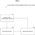
- FIG. 1 is a block diagram illustrating an example of the overall configuration of the nucleoside phosphoramidite identifying system according to the present embodiment.
- the nucleoside phosphoramidite identifying system 1 includes a nucleic acid synthesizing device 10, a detecting device 20, and an identifying device 30.
- the detecting device 20 is optically connected to a flow cell provided on a tube of the nucleic acid synthesizing device 10.
- the identifying device 30 is electrically connected to the nucleic acid synthesizing device 10 and the detecting device 20.
- the nucleic acid synthesizing device 10 is a nucleic acid synthesizing device configured to synthesize an oligonucleotide.
- the nucleic acid synthesizing device 10 includes a plurality of tanks in which acetonitrile solutions containing various types of nucleoside phosphoramidites used for synthesizing oligonucleotides, a solution containing an activating agent, a solution containing a deprotection agent, a solution containing an oxidizing agent or a thiolation agent, a solution containing a capping agent, an acetonitrile for washing, and an amine wash reaction solution are stored, and a column in which an oligonucleotide is synthesized.
- the tanks and the column are connected through a tube via a pump.
- the pump is configured to perform a control to deliver a nucleoside phosphoramidite solution to the column from any one of the tanks according to sequence information of an oligonucleotide.
- the tube that connects the pump and the column is provided with a flow cell to which various measuring instruments are connected.
- the identifying device 30 identifies the type of the nucleoside phosphoramidite to be delivered to the column based on the cosine similarity between the infrared absorption spectra, which are the references stored in the memory unit, and the infrared absorption spectrum of the nucleoside phosphoramidite solution, which is the detection target detected by the detecting device 20.
- the overall configuration of the nucleoside phosphoramidite identifying system 1 illustrated in FIG. 1 is an example, and there are possibly various system configuration examples depending on the use or purpose.
- the identifying device 30 may be realized by a plurality of computers, and may be realized as a cloud computing service.
- the nucleoside phosphoramidite identifying system 1 may be realized by a standalone information processing device comprehensively equipped with the functions, which the detecting device 20 and the identifying device 30 must have.
- FIG. 2 is a block diagram illustrating an example of the hardware configuration of the nucleic acid synthesizing device 10 according to the present embodiment.
- the nucleic acid synthesizing device 10 according to the present embodiment includes a tank 11, a pump 12, a tube 13, a flow cell 14, a column 15, and a waste liquid tank 16.
- the tank 11 is configured to store acetonitrile solutions containing nucleoside phosphoramidites.
- the tank 11 is formed of a plurality of tanks, and the tanks each store the acetonitrile solution containing one type of a nucleoside phosphoramidite, the solution containing the activating agent (unillustrated), the solution containing the deprotection agent (unillustrated), the solution containing the oxidizing agent (unillustrated) or the thiolation agent (unillustrated), the solution containing the capping agent (unillustrated), the acetonitrile for washing (unillustrated), and the amine wash reaction solution (unillustrated), respectively.
- nucleoside phosphoramidites containing, as DNA bases, adenine (hereinafter, represented as "dA”), thymine (hereinafter, represented as “dT”), guanine (hereinafter, represented as “dG”), cytosine (hereinafter, represented as “dC”), and 5-methyl-cytosine (hereinafter, represented as “5MedC”) are stored in the tank 11.
- Nucleoside phosphoramidites are not limited to those mentioned above, and may be other DNA modifiers, RNA, and RNA modifiers.
- the pump 12 is connected to the tank 11 and the column 15 through the tube 13.
- the pump 12 is configured to deliver a nucleoside phosphoramidite solution from the tank 11 to the column 15.
- the pump 12 is controlled to deliver a nucleoside phosphoramidite solution of any type to the column 15 in order according to the sequence information of an oligonucleotide.
- the flow cell 14 is provided on the tube 13 that connects the pump 12 and the column 15.
- the flow cell 14 is configured such that various types of measuring instruments can be optically connected to the flow cell 14.
- the column 15 is a reaction container in which the nucleoside phosphoramidites, the activating agent, the deprotection agent, the oxidizing agent or the thiolation agent, and the capping agent that are delivered from the tank 11 via the pump 12 react with each other, to produce an oligonucleotide.
- a nucleic acid synthesizing process including such steps as deprotection, coupling, oxidization or thiolation, and capping is performed.
- the waste liquid tank 16 is connected to the column 15 through the tube 13.
- the solution exhausted in the column 15 is discarded into the waste liquid tank 16.
- the hardware configuration of the nucleic acid synthesizing device 10 illustrated in FIG. 2 is an example.
- the nucleic acid synthesizing device 10 according to the present embodiment may have any hardware configuration, so long as a spectrum can be detected from a nucleoside phosphoramidite solution to be delivered to the column 15.
- FIG. 3 is a block diagram illustrating an example of the hardware configuration of a computer 500 according to the present embodiment.
- the computer 500 includes a Central Processing Unit (CPU) 501, a Read Only Memory (ROM) 502, a Random Access Memory (RAM) 503, a Hard Disk Drive (HDD) 504, an input device 505, a display device 506, a communication interface (I/F) 507, and an external I/F 508.
- the CPU 501, the ROM 502, and the RAM 503 form what is generally referred to as a computer.
- the respective hardware pieces of the computer 500 are mutually connected through a bus line 509.
- the input device 505 and the display device 506 may be used while being connected to the external I/F 508.
- the CPU 501 is an operating device configured to realize controls and functions of the entirety of the computer 500 by reading out programs and data onto the RAM 503 from a memory device such as the ROM 502 or the HDD 504 and executing processes.
- the ROM 502 is an example of a nonvolatile semiconductor memory (memory device) that can retain programs and data even when power supply is cut.
- the ROM 502 functions as a main memory device configured to store, for example, various programs and data necessary for the CPU 501 to execute various programs installed on the HDD 504.
- the ROM 502 stores boot programs such as Basic Input/Output System (BIOS) and Extensible Firmware Interface (EFI) that are executed when the computer 500 is started, and data such as Operating System (OS) settings and network settings.
- BIOS Basic Input/Output System
- EFI Extensible Firmware Interface
- the RAM 503 is an example of a volatile semiconductor memory (memory device) from which programs and data are erased when power supply is cut.
- the RAM 503 is, for example, a Dynamic Random Access Memory (DRAM) or a Static Random Access Memory (SRAM).
- DRAM Dynamic Random Access Memory
- SRAM Static Random Access Memory
- the RAM 503 provides a work area in which various programs installed on the HDD 504 are deployed when executed by the CPU 501.
- the HDD 504 is an example of a nonvolatile memory device storing programs and data.
- the programs and data stored in the HDD 504 include OS, which is basic software for controlling the entirety of the computer 500, and applications that provide various functions on the OS.
- the computer 500 may employ a memory device using a flash memory as a memory medium (e.g., a Solid State Drive (SSD)), instead of the HDD 504.
- SSD Solid State Drive
- the input device 505 is, for example, a touch panel, operation keys or buttons, or a keyboard or a mouse by which a user enters various signals, or a microphone by which a user enters sound data such as sound or voice.
- the display device 506 is formed of a liquid crystal or organic Electro-Luminescence (EL) display configured to display a screen, and a loudspeaker configured to output sound data such as sound and voice.
- EL Electro-Luminescence
- the communication I/F 507 is an interface configured to connect to a communication network in order that the computer 500 can perform data communication.
- the external I/F 508 is an interface to an external device.
- An example of the external device is a drive device 510.
- the drive device 510 is a device configured for a recording medium 511 to be set therein.
- the recording medium 511 meant here encompasses media configured to record information optically, electrically, or magnetically, such as a CD-ROM, a flexible disk, and a magneto-optical disk.
- the recording medium 511 may also encompass, for example, semiconductor memories configured to record information electrically, such as a ROM and a flash memory.
- the computer 500 can perform either or both of reading from and writing into the recording medium 511 via the external I/F 508.
- Various programs to be installed on the HDD 504 are installed by, for example, a distributed recording medium 511 being set in the drive device 510 connected to the external I/F 508, and various programs recorded in the recording medium 511 being read out by the drive device 510.
- various programs to be installed on the HDD 504 may be installed by being downloaded from any other network different from the communication network via the communication I/F 507.
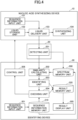
- FIG. 4 is a block diagram illustrating an example of the functional configuration of the nucleoside phosphoramidite identifying system according to the present embodiment.
- the sequence information input unit 101 is also configured to receive an input of a liquid delivery condition under which the liquid delivery unit 103 delivers a nucleoside phosphoramidite solution of each type individually, and individual information exclusively regarding the nucleoside phosphoramidite of the type to be delivered, in response to an operation of a user.
- the nucleic acid synthesizing device 10 delivers the nucleoside phosphoramidite solution of each type individually in accordance with the liquid delivery condition and the individual information (hereinafter, may also be represented as individual information, etc.) without performing nucleic acid synthesis (hereinafter, this mode may also be represented as an individual liquid delivery mode).
- the liquid storage unit 102 stores the various types of nucleoside phosphoramidite solutions, the solution containing the activating agent, the solution containing the deprotection agent, the solution containing the oxidizing agent or the thiolation agent, the solution containing the capping agent, the acetonitrile for washing, and the amine wash reaction solution.
- the liquid storage unit 102 is realized by, for example, the tank 11 illustrated in FIG. 2 .
- the liquid delivery unit 103 is configured to deliver the nucleoside phosphoramidite solutions, the solution containing the activating agent, the solution containing the deprotection agent, the solution containing the oxidizing agent or the thiolation agent, the solution containing the capping agent, the acetonitrile for washing, or the amine wash reaction solution stored in the liquid storage unit 102 to the synthesizing unit 104 in order in accordance with the sequence information, etc. received by the sequence information input unit 101.
- the liquid delivery unit 103 is realized by, for example, the pump 12 and the tube 13 illustrated in FIG. 2 .
- the synthesizing unit 104 is configured to synthesize an oligonucleotide by a predetermined nucleic acid synthesizing method using the nucleoside phosphoramidite solutions, the solution containing the activating agent, the solution containing the deprotection agent, the solution containing the oxidizing agent or the thiolation agent, the solution containing the capping agent, the acetonitrile for washing, and the amine wash reaction solution delivered by the liquid delivery unit 103.
- the synthesizing unit 104 is realized by, for example, the column 15 illustrated in FIG. 2 .
- the detecting device 20 includes a detecting unit 201.
- the detecting unit 201 is realized by a process, which the CPU 501 is caused to execute by a program deployed in the RAM 503 from the HDD 504 illustrated in FIG. 3 .
- the detecting unit 201 is configured to detect an infrared absorption spectrum from a nucleoside phosphoramidite solution delivered by the liquid delivery unit 103.
- the infrared absorption spectrum detected by the detecting unit 201 may also be referred to as a "detected spectrum”.
- the detecting unit 201 is configured to output a detected spectrum to the identifying device 30.
- the identifying device 30 includes a spectrum memory unit 300, a sequence information input unit 301, a similarity calculating unit 302, an identifying unit 303, a checking unit 304, a result display unit 305, a control unit 306, a sequence information memory unit 310, and a result memory unit 320.
- the sequence information input unit 301, the similarity calculating unit 302, the identifying unit 303, the checking unit 304, the result display unit 305, and the control unit 306 are realized by processes, which the CPU 501 is caused to execute by a program deployed in the RAM 503 from the HDD 504 illustrated in FIG. 3 .
- the spectrum memory unit 300, the sequence information memory unit 310, and the result memory unit 320 are realized by, for example, using the HDD 504 illustrated in FIG. 3 .
- the spectrum memory unit 300 is configured to store infrared absorption spectra that have been previously detected as references from identifying-target nucleoside phosphoramidites in the individual liquid delivery mode.
- the infrared absorption spectra stored in the spectrum memory unit 300 may also be referred to as "identifying-target spectra".
- the identifying-target spectra are stored in the spectrum memory unit 300 in association with individual information regarding various types of nucleoside phosphoramidites input via the sequence information input unit 301.
- Identifying-target nucleoside phosphoramidites are nucleoside phosphoramidites of various types included in sequence information of an oligonucleotide to be synthesized by the nucleic acid synthesizing device 10.
- identifying-target nucleoside phosphoramidites are nucleoside phosphoramidites of various types that are stored in the liquid storage unit 102 of the nucleic acid synthesizing device 10.
- the identifying-target spectra stored in the spectrum memory unit 300 for various types of nucleoside phosphoramidites may each include a plurality of infrared absorption spectra that are detected using nucleoside phosphoramidite solutions prepared at different concentrations. With this configuration, it is possible to identify also the concentrations of the acetonitrile solutions in addition to the types of the nucleoside phosphoramidites.
- the sequence information input unit 301 is configured to receive an input of sequence information of an oligonucleotide for the nucleic acid synthesizing mode, or individual information of a nucleoside phosphoramidite of each type for the individual liquid delivery mode in response to an operation of a user.
- the sequence information memory unit 310 is configured to store sequence information of an oligonucleotide or individual information of a nucleoside phosphoramidite of each type received by the sequence information input unit 301.
- the similarity calculating unit 302 is configured to calculate the cosine similarity between each of the identifying-target spectra stored in the spectrum memory unit 300 and a detected spectrum detected by the detecting device 20.
- the identifying unit 303 is configured to identify the type of a nucleoside phosphoramidite delivered by the liquid delivery unit 103 of the nucleic acid synthesizing device 10 based on the cosine similarity calculated by the similarity calculating unit 302. Specifically, the identifying unit 303 determines the identifying-target spectrum corresponding to the maximum cosine similarity among the cosine similarities calculated by the similarity calculating unit 302 (i.e., determines the identifying-target spectrum that is the most similar to the detected spectrum). Next, the identifying unit 303 determines the type of the nucleoside phosphoramidite corresponding to the determined identifying-target spectrum, as the type of the nucleoside phosphoramidite delivered.
- the checking unit 304 is configured to check the nucleoside phosphoramidite identification result of the identifying unit 303 against the sequence information or the individual information stored in the sequence information memory unit 310. Specifically, the checking unit 304 first determines the correct nucleoside phosphoramidite that is supposed to be being delivered currently, according to the sequence information or the individual information. Next, the checking unit 304 determines whether the correct nucleoside phosphoramidite matches the nucleoside phosphoramidite identification result of the identifying unit 303.
- the result memory unit 320 is configured to store the identification result of the identifying unit 303 and the checking result of the checking unit 304 in association with each other.
- the result display unit 305 is configured to display the identification result and the checking result stored in the result memory unit 320 on a display device 506 in association with each other. Here, when the checking result indicates a mismatch, the result display unit 305 displays an alert to that effect.
- the control unit 306 is configured to control the nucleic acid synthesizing device 10 to stop liquid delivery when the checking result of the checking unit 304 indicates a mismatch.
- Examples of the method for stopping liquid delivery include a method of closing the tube 13 such that the solution cannot flow, and a method of sending a control signal to stop the pump 12, although the method is different depending on the nucleic acid synthesizing device 10.
- FIG. 5 is a flowchart illustrating an example of the process flow of the nucleoside phosphoramidite identifying method according to the present embodiment.
- the sequence information input unit 101 of the nucleic acid synthesizing device 10 receives an input of sequence information, etc. of an oligonucleotide, or individual information, etc. of a nucleoside phosphoramidite of each type in response to an operation of a user.
- the sequence information input unit 101 sends the received sequence information, etc. or individual information, etc. to the liquid delivery unit 103.
- the sequence information input unit 301 of the identifying device 30 receives an input of sequence information of an oligonucleotide or individual information of a nucleoside phosphoramidite of each type in response to an operation of the user.
- the sequence information input unit 301 stores the received sequence information or individual information in the sequence information memory unit 310.
- the liquid delivery unit 103 of the nucleic acid synthesizing device 10 delivers the nucleoside phosphoramidite solutions, the solution containing the activating agent, the solution containing the deprotection agent, the solution containing the oxidizing agent or the thiolation agent, the solution containing the capping agent, the acetonitrile for washing, or the amine wash reaction solution stored in the liquid storage unit 102 to the synthesizing unit 104 in order in accordance with the sequence information, etc. received from the sequence information input unit 101.
- the liquid delivery unit 103 delivers a nucleoside phosphoramidite solution stored in the liquid storage unit 102 to the synthesizing unit 104 in accordance with the individual information, etc. received from the sequence information input unit 101.
- the liquid delivery unit 103 may receive sequence information of an oligonucleotide or individual information of a nucleoside phosphoramidite of each type from the sequence information input unit 301.
- the synthesizing unit 104 of the nucleic acid synthesizing device 10 determines whether the mode is the nucleic acid synthesizing mode or the individual liquid delivery mode. When the mode is the nucleic acid synthesizing mode (YES), the synthesizing unit 104 forwards the flow to the step S3- 2. When the mode is the individual liquid delivery mode (NO), the synthesizing unit 104 skips the step S3-2.
- the synthesizing unit 104 of the nucleic acid synthesizing device 10 synthesizes an oligonucleotide according to a predetermined nucleic acid synthesizing method using the nucleoside phosphoramidites, the activating agent, the deprotection agent, the oxidizing agent or the thiolation agent, and the capping agent delivered by the liquid delivery unit 103.
- the detecting unit 201 of the detecting device 20 detects an infrared absorption spectrum from a nucleoside phosphoramidite solution delivered by the liquid delivery unit 103.
- the detecting unit 201 outputs the detected spectrum to the identifying device 30.
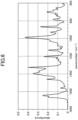
- FIG. 6 is a drawing illustrating an example of an infrared absorption spectrum.
- FIG. 6 is an example of an infrared absorption spectrum detected from a dT nucleoside phosphoramidite.
- the example of FIG. 6 is an infrared absorption spectrum detected from a dT nucleoside phosphoramidite-containing acetonitrile solution prepared at a concentration of 200 mM.
- the horizontal axis represents wavenumber
- the vertical axis represents absorbance.
- the similarity calculating unit 302 of the identifying device 30 receives an input of the detected spectrum output by the detecting device 20.
- the similarity calculating unit 302 reads out the identifying-target spectra stored in the spectrum memory unit 300.
- the similarity calculating unit 302 calculates the cosine similarity between an identifying-target spectrum and the detected spectrum, for each identifying-target spectrum.
- the similarity calculating unit 302 sends the cosine similarities corresponding to the respective identifying-target spectra to the identifying unit 303.
- the identifying unit 303 of the identifying device 30 receives the cosine similarities from the similarity calculating unit 302. Next, the identifying unit 303 determines the identifying-target spectrum corresponding to the maximum cosine similarity among the received cosine similarities. Next, the identifying unit 303 determines the type of the nucleoside phosphoramidite corresponding to the determined identifying-target spectrum, as the type of the nucleoside phosphoramidite delivered.
- the identifying unit 303 sends the identification result indicating the type of the determined nucleoside phosphoramidite to the checking unit 304. Next, the identifying unit 303 stores the identification result in the result memory unit 320.
- the identifying unit 303 need not send the identification result to the checking unit 304, and may need only to store the identification result in the result memory unit 320. In this case, the identifying unit 303 skips the step S7 and forwards the flow to the step S8.
- the checking unit 304 of the identifying device 30 receives the identification result from the identifying unit 303.
- the checking unit 304 determines the correct nucleoside phosphoramidite that is supposed to be being delivered currently, according to the sequence information or the individual information stored in the sequence information memory unit 310.
- the checking unit 304 determines whether the correct nucleoside phosphoramidite and the nucleoside phosphoramidite identification result match each other.
- the checking unit 304 stores a checking result indicating whether the correct answer and the identification result match each other or not in the result memory unit 320.
- the result display unit 305 of the identifying device 30 displays the identification result and the checking result that are stored in the result memory unit 320 on the display device 506 in association with each other.
- the result display unit 305 displays an alert to that effect.
- the result display unit 305 may output an alerting sound from the loudspeaker of the display device 506.
- the result display unit 305 displays the identification result stored in the result memory unit 320 on the display device 506.
- FIG. 7 is a concept drawing illustrating an example of the result display screen according to the present embodiment.
- the result display screen 1000 includes a sequence information input field 1001, a sequence information display field 1002, an identification result display field 1003, a checking result display field 1004, a start button 1008, and a cancel button 1009.
- the sequence information input field 1001 receives an input of sequence information of an oligonucleotide or individual information of a nucleoside phosphoramidite of each type in response to an operation of a user.
- sequence information or individual information When the user inputs sequence information or individual information and depresses the start button 1008, nucleoside phosphoramidite identification is started.
- the sequence information display field 1002 displays a predetermined number of nucleoside phosphoramidites that are to be delivered from that instant. In the example in FIG. 7 , it is indicated that dA, 5MedC, dC, dT, and dG need to be delivered in this order.
- the identification result display field 1003 displays identification results corresponding to each sequence information in order. In the example in FIG. 7 , it is indicated that dA, 5MedC, and dT have been identified in this order. "-" indicates that identification has not been performed yet.
- the checking result display field 1004 displays checking results corresponding to the respective identification results in order.
- the checking result display field 1004 displays the checking results by color variation.
- white represents a match
- halftone represents a mismatch
- black represents "not identified yet”.
- any colors may be used so long as the user can easily discern the colors.
- “match” may be set to green
- "mismatch” may be set to red
- "not identified yet” may be set to gray.
- the display style of the checking results is not limited to color variation, and any display style may be used so long as the user can easily understand the checking results by the display style.
- the checking result display field 1004 is not displayed on the result display screen 1000.
- the checking unit 304 of the identifying device 30 determines whether the checking result in the step S7 indicates a match or not (i.e., whether the identification result matches the sequence information or the individual information). When the checking result indicates a match (YES), the checking unit 304 returns the flow to the step S5, in which a detected spectrum of a nucleoside phosphoramidite to be delivered next is awaited. When the checking result indicates a mismatch (NO), the checking unit 304 forwards the flow to the step S10.
- the control unit 306 of the identifying device 30 controls the nucleic acid synthesizing device 10 to stop liquid delivery.
- this control is a control to close the tube 13 of the nucleic acid synthesizing device 10.
- this control may also be a control to send a signal to stop the pump 12 of the nucleic acid synthesizing device 10.
- the liquid delivery unit 103 of the nucleic acid synthesizing device 10 stops liquid delivery in response to the control from the control unit 306. For example, when the tube 13 is closed, the nucleic acid synthesizing device 10 senses a liquid delivery abnormity and automatically stops liquid delivery. For example, when a signal to stop the pump 12 is received, the nucleic acid synthesizing device 10 stops the pump 12 in response to the stop signal.
- the nucleoside phosphoramidite identifying system identifies the type of a nucleoside phosphoramidite based on the cosine similarity between an infrared absorption spectrum detected from a nucleoside phosphoramidite solution and infrared absorption spectra that have been previously detected from various types of nucleoside phosphoramidite solutions and stored as references.
- the nucleic acid synthesizing device delivers a nucleoside phosphoramidite solution from the tank to the column
- the concentration of the nucleoside phosphoramidite solution changes in the tube. This is because the interior of the tube needs to be washed with acetonitrile between the steps of the nucleic acid synthesizing method, so the nucleoside phosphoramidite solution is delivered by being injected into the tube filled with acetonitrile.
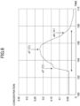
- FIG. 8 is a graph plotting the results of measuring the concentration of a dT nucleoside phosphoramidite solution at a spectral intensity of 1,250 cm -1 during liquid delivery, and the results of identifying the measured results by an existing PLS discrimination method.
- the concentration of the nucleoside phosphoramidite solution gradually decreases near the end of the liquid delivery.
- the existing PLS discrimination method erroneously determines the solution as dA.
- the PLS discrimination method calculates the similarity by focusing on, for example, the position and height of a spectral peak. Hence, if a peak appears at a different position or height under the effects of noise, the likelihood of erroneous identification increases. On the other hand, according to the cosine similarity, the focus is on the spectral shape when the similarity is calculated. Hence, even if a peak appears at a different position or height under the effects of noise, a correct identification can be obtained so long as a significantly different spectral shape is not detected.
- the nucleoside phosphoramidite identifying system has a nucleoside phosphoramidite identification accuracy improved over the existing techniques.
- the first embodiment is configured to identify the type of a nucleoside phosphoramidite based on an infrared absorption spectrum detected from a nucleoside phosphoramidite solution, using an infrared spectroscope as the detecting device 20.
- the second embodiment is configured to identify the type of a nucleoside phosphoramidite based on a Raman spectrum detected from a nucleoside phosphoramidite solution, using a Raman spectroscope as the detecting device 20.
- the nucleoside phosphoramidite identifying system 1 according to the present embodiment will be described below, mainly regarding differences from the nucleoside phosphoramidite identifying system 1 according to the first embodiment.
- the detecting device 20 is a Raman spectroscope configured to decompose Raman-scattered light, which is generated in response to irradiation of a nucleoside phosphoramidite solution delivered to a column with laser, into spectra.
- the detecting unit 201 is configured to detect a Raman spectrum from a nucleoside phosphoramidite solution delivered by the liquid delivery unit 103.
- the detecting unit 201 is also configured to output the detected Raman spectrum to the identifying device 30.
- the spectrum memory unit 300 is configured to store Raman spectra previously detected from identifying-target nucleoside phosphoramidites.
- the Raman spectra stored in the spectrum memory unit 300 may also be referred to as "identifying-target spectra”.
- the similarity calculating unit 302 is configured to calculate the cosine similarity between each Raman spectrum stored in the spectrum memory unit 300 and a Raman spectrum detected by the detecting device 20.
- the identifying unit 303 is configured to identify the type of the nucleoside phosphoramidite delivered by the liquid delivery unit 103 of the nucleic acid synthesizing device 10 based on the cosine similarity calculated by the similarity calculating unit 302.
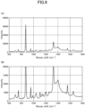
- FIG. 9 includes drawings illustrating examples of Raman spectra.
- FIG. 9 illustrates examples of Raman spectra detected from a dC nucleoside phosphoramidite.
- the examples in FIG. 9 are Raman spectra detected from an acetonitrile solution prepared at a concentration of 100 mM.
- the horizontal axis represents Raman shift
- the vertical axis represents light intensity.
- FIG. 9 (A) is a graph plotted in a light intensity range of from 0 through 80000
- FIG. 9 (B) is a graph plotted in a magnified light intensity range of from 0 through 20000.
- the nucleoside phosphoramidite identifying system identifies the type of a nucleoside phosphoramidite based on the cosine similarity between a Raman spectrum detected from a nucleoside phosphoramidite solution and Raman spectra that have been previously detected from various types of nucleoside phosphoramidite solutions and stored as references.
- the nucleoside phosphoramidite identifying system has a nucleoside phosphoramidite identification accuracy improved over the existing techniques.
- control unit 306 is configured to control the nucleic acid synthesizing device 10 to stop liquid delivery when a result of checking sequence information and an identification result is a mismatch.
- control unit 306 is configured to control the nucleic acid synthesizing device 10 to discard the nucleoside phosphoramidite solution being delivered.
- the nucleoside phosphoramidite identifying system 1 according to the present embodiment will be described below, mainly regarding differences from the nucleoside phosphoramidite identifying system 1 according to the first embodiment.
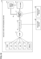
- FIG. 10 is a block diagram illustrating an example of the hardware configuration of the nucleic acid synthesizing device 10 according to the present embodiment. As illustrated in FIG. 10 , the nucleic acid synthesizing device 10 according to the present embodiment is different from the nucleic acid synthesizing device 10 according to the first embodiment in further including an electromagnetic valve 17 and a waste liquid tube 18.
- the electromagnetic valve 17 is provided on the tube 13 that connects the flow cell 14 and the column 15.
- the electromagnetic valve 17 is further connected to the waste liquid tank 16 through the waste liquid tube 18.
- the electromagnetic valve 17 is electrically connected to the identifying device 30.
- the electromagnetic valve 17 is controlled to deliver a nucleoside phosphoramidite solution, which is delivered in the tube 13, to the waste liquid tube 18 in accordance with a control signal received from the identifying device 30.
- the path that leads to the waste liquid tank 16 from the electromagnetic valve 17 through the waste liquid tube 18 may also be referred to as a "discarding path".
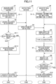
- FIG. 11 is a flowchart illustrating an example of the process flow of the nucleoside phosphoramidite identifying method according to the present embodiment.
- the nucleoside phosphoramidite identifying method according to the present embodiment is different from the nucleoside phosphoramidite identifying method according to the first embodiment in the processes of the steps S10 and S11.
- the control unit 306 of the identifying device 30 controls the nucleic acid synthesizing device 10 to discard a nucleoside phosphoramidite solution.
- this control is a control to send a control signal to the electromagnetic valve 17 of the nucleic acid synthesizing device 10 to request the electromagnetic valve 17 to deliver a nucleoside phosphoramidite solution to the waste liquid tube 18.
- the liquid delivery unit 103 of the nucleic acid synthesizing device 10 delivers the nucleoside phosphoramidite solution to the waste liquid tank 16 in accordance with the control from the control unit 306. Specifically, the nucleic acid synthesizing device 10 controls the electromagnetic valve 17 such that the nucleoside phosphoramidite solution is delivered to the waste liquid tube 18.
- Example 1 nucleoside phosphoramidite identification in the individual liquid delivery mode was performed using the nucleoside phosphoramidite identifying system according to the first embodiment. Example 1 will be described below with reference to FIG. 12 to FIG. 14 .
- a determination test was performed in the present Example and Comparative Example described below, using the same nucleic acid synthesizing device. In the determination test, a determination success rate was examined for each individual concentration level (individual liquid delivery mode), not for the type of a nucleoside phosphoramidite being synthesized (nucleic acid synthesizing mode).
- nucleoside phosphoramidites (dA, dG, dT, and dC) were prepared at 25 mM, 50 mM, 100 mM, and 200 mM. Subsequently, using the nucleic acid synthesizing device, the various types of nucleoside phosphoramidite solutions were delivered to the flow cell of an infrared spectroscope (REACT IR15 (registered trademark) obtained from Mettler Toledo (registered trademark) International Inc.) connected through a plastic tube, to measure the infrared absorption spectra of the flowing acetonitrile solutions.
- infrared spectroscope REACT IR15 (registered trademark) obtained from Mettler Toledo (registered trademark) International Inc.
- the measurement conditions of the infrared microscope were as follows.
- the measurement wavenumber range was from 1,850 cm -1 through 650 cm -1 .
- the wavenumber resolution was 8 cm -1 .
- the number of times to add up was 16 times.
- the infrared absorption spectra obtained according to the procedure described above were stored in the spectrum memory unit 300 of the identifying device 30 as references in association with individual information of the nucleoside phosphoramidites of the respective types.
- Acetonitrile solutions of nucleoside phosphoramidites (dA, dG, dT, and dC) were prepared at 6.25 mM, 12.5 mM, 25 mM, 50 mM, 100 mM, and 200 mM. Subsequently, using the nucleic acid synthesizing device, the various types of nucleoside phosphoramidite solutions were delivered to the flow cell of the infrared spectroscope mentioned above connected through a plastic tube, to measure the infrared absorption spectra of the flowing acetonitrile solutions. The measurement conditions of the infrared microscope were the same as when the references were obtained.
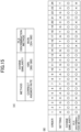
- FIG. 12 is a diagram indicating the number of infrared absorption spectrum data detected under the conditions specified above, per solution concentration and per nucleoside phosphoramidite type.
- FIG. 13 is a diagram indicating the identification results in the present Example.
- FIG. 13 is a table indicating the determination success rate in each determination test.
- nucleoside phosphoramidites As in the present Example, previously measured infrared absorption spectra of nucleoside phosphoramidites (dA, dG, dT, and dC) were prepared as references. After infrared absorption spectra detected by the infrared spectroscope mentioned above were stored in the result memory unit 320 of the identifying device 30, the types of the nucleoside phosphoramidites of the infrared absorption spectra were determined by the PLS discrimination method.
- FIG. 14 is a diagram indicating the identification results in the present Comparative Example.
- FIG. 14 is a table indicating the determination success rate in each determination test.
- nucleoside phosphoramidites could be correctly identified at relatively high concentrations higher than or equal to 50 mM in both of the present Comparative Example and the present Example.
- erroneous identification occurred at 25 mM, and there was a tendency that the lower the concentration, the more erroneous identification cases occurred.
- all types of nucleoside phosphoramidites could be correctly identified even at low concentrations lower than or equal to 25 mM.
- the present Example achieved a result that the identification accuracy of the nucleoside phosphoramidite identifying system according to the first embodiment was better than that of the existing method.
- Example 2 the type of a nucleoside phosphoramidite delivered in the nucleic acid synthesizing device was identified in the nucleic acid synthesizing mode, using the nucleoside phosphoramidite identifying system according to the first embodiment. Example 2 will be described below with reference to FIG. 15 .
- the activating agent was entirely dissolved in acetonitrile, and prepared at 0.7 M.
- Other synthesizing reagents were as follows. DCA having a concentration of 3% in toluene was used as a deprotection agent. A 0.05 M oxidizing solution prepared exclusively for the aforementioned nucleic acid synthesizing device to be used was used as an oxidizing agent. A mixture solution of lutidine, N-methyl imidazole, and acetic anhydride in acetonitrile was used as a capping agent. The interiors of the tube and the synthesizing column were washed with acetonitrile between the coupling step, the oxidizing step, the capping step, and the deprotection step.
- FIG. 15 (A) is a diagram indicating the identification results in the present Example. As indicated in FIG. 15 , in the present Example, 360 samples out of the 360 samples were correctly identified, and all types of nucleoside phosphoramidites could be correctly identified. On the other hand, according to the existing PLS discrimination method, 324 samples out of the 360 samples were correctly identified, and 36 samples were erroneously identified.
- FIG. 15 (B) was a diagram indicating the order of delivering the nucleoside phosphoramidites, and the identification results with respect to the set sequence information.
- a cycle in which all of the 15 samples were correctly identified is denoted as "o”
- a cycle in which one or more samples were erroneously identified is denoted as " ⁇ ”.
- erroneous identifications occurred during delivery of dT and dC.
- the present Example achieved a result that the identification accuracy of the nucleoside phosphoramidite identifying system according to the first embodiment was better than that of the existing method, even for nucleoside phosphoramidites that were being synthesized.
- acetonitrile solutions of four types of modified nucleoside phosphoramidites (2'OMerA, 2'OMerC, 2'OMerG, and 5MedC) prepared at 200 mM were delivered to the flow cell of the infrared spectroscope connected through a plastic tube, to measure the infrared absorption spectra of the flowing acetonitrile solutions.
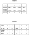
- FIG. 16 is a diagram indicating the identification results in the present Example. As indicated in FIG. 16 , according to the cosine similarity, all types of nucleoside phosphoramidites were correctly identified. Hence, it was indicated that not only unmodified nucleoside phosphoramidites, but also modified nucleoside phosphoramidites could be identified based on the cosine similarity. From the identification results in FIG. 16 and the identification results in Example 2 indicated in FIG. 15 (in the nucleic acid synthesizing mode), it is inferred that modified nucleoside phosphoramidites would also be correctly identified under the nucleic acid synthesizing condition (nucleic acid synthesizing mode).
- Example 4 nucleoside phosphoramidite identification in the individual liquid delivery mode was performed using the nucleoside phosphoramidite identifying system according to the second embodiment (i.e., using Raman spectra). Example 4 will be described below with reference to FIG. 17 .
- nucleoside phosphoramidite solutions were delivered to a flow cell-integrated probe (obtained from Marq Metrix) of a Raman spectroscope (PI-200 obtained from Process Instruments Inc.) connected through a plastic tube using a single plunger pump (SP-21 obtained from Flom, Inc.), to measure Raman spectra of the flowing acetonitrile solutions.
- PI-200 obtained from Process Instruments Inc.
- SP-21 obtained from Flom, Inc.
- the Raman spectra obtained according to the procedure described above were stored in the spectrum memory unit 300 of the identifying device 30 as references in association with individual information of the nucleoside phosphoramidites of the respective types.
- nucleoside phosphoramidite (dA, dC, 5MedC, dT, and dG) were prepared at 200 mM, and then set in a duct of the nucleic acid synthesizing device.
- the five types of nucleoside phosphoramidites were delivered to the flow cell-integrated probe of the Raman spectroscope in the order of dA, dC, 5MedC, dT, and dG under software setting of the nucleic acid synthesizing device.
- FIG. 17 is a diagram indicating the identification results in the present Example. As indicated in FIG. 17 , the five types of nucleoside phosphoramidites were delivered, and the types of all of the nucleoside phosphoramidites were correctly identified. From the Raman spectrum identification results in FIG. 17 and the identification results in Example 2 indicated in FIG. 15 (likewise using the cosine similarity in the nucleic acid synthesizing mode), it is inferred that all types of nucleoside phosphoramidites would be correctly identified also under the nucleic acid synthesizing condition (nucleic acid synthesizing mode) based on Raman spectrum detection and cosine similarity.
Landscapes
- Physics & Mathematics (AREA)
- Health & Medical Sciences (AREA)
- Life Sciences & Earth Sciences (AREA)
- Engineering & Computer Science (AREA)
- Spectroscopy & Molecular Physics (AREA)
- General Health & Medical Sciences (AREA)
- Theoretical Computer Science (AREA)
- Medical Informatics (AREA)
- Biotechnology (AREA)
- Bioinformatics & Computational Biology (AREA)
- Chemical & Material Sciences (AREA)
- Evolutionary Biology (AREA)
- Bioinformatics & Cheminformatics (AREA)
- Databases & Information Systems (AREA)
- Biophysics (AREA)
- Pathology (AREA)
- Bioethics (AREA)
- Immunology (AREA)
- General Physics & Mathematics (AREA)
- Biochemistry (AREA)
- Analytical Chemistry (AREA)
- Signal Processing (AREA)
- Public Health (AREA)
- Software Systems (AREA)
- Nuclear Medicine, Radiotherapy & Molecular Imaging (AREA)
- Evolutionary Computation (AREA)
- Epidemiology (AREA)
- Data Mining & Analysis (AREA)
- Computer Vision & Pattern Recognition (AREA)
- Artificial Intelligence (AREA)
- Molecular Biology (AREA)
- Saccharide Compounds (AREA)
- Apparatus Associated With Microorganisms And Enzymes (AREA)
- Measuring Or Testing Involving Enzymes Or Micro-Organisms (AREA)
Abstract
Description
- The present invention relates to a nucleoside phosphoramidite identifying system, a nucleoside phosphoramidite identifying method, and a program.
- There is a nucleic acid synthesizing device configured to synthesize an oligonucleotide by binding nucleoside phosphoramidites according to sequence information. For example,
Patent Document 1 discloses a nucleic acid synthesizing device including a deprotection unit, a coupling unit, an oxidizing/thiolation unit, a capping unit, and a washing unit, wherein a plurality of reaction containers are conveyed to these units according to a synthesis scheme for a desired nucleic acid sequence. - There is a real-time monitoring technique for detecting errors in a nucleic acid synthesizing process. For example, Non-Patent
Document 1 discloses a technique for real-time monitoring of an acetonitrile solution of a nucleoside phosphoramidite delivered to a reaction container, using an infrared spectroscope. The technique described inNon-Patent Document 1 identifies the type of the delivered nucleoside phosphoramidite by analyzing an infrared absorption spectrum, which is detected by the infrared spectroscope, by a Partial Least Squares Discriminant Analysis (PLS-DA) (hereinafter, may also be referred to as "PLS discrimination method"). - [Patent document 1] International Publication No.
WO 2020/210476 - [Non-Patent Document 1] John-David McElderry, Daniel Hill, Elliott Schmitt, Xiaoye Su, and Jessica Stolee, "In-line Phosphoramidite Identification by FTIR to Support Real-Time Oligonucleotide Sequence Confirmation," Organic Process Research & Development 2021, 25, 2, 262-270.
- However, the PLS discrimination method has a problem that the nucleoside phosphoramidite discrimination accuracy is low. Particularly, there is a tendency that the lower the concentration of a nucleoside phosphoramidite, the more likely a discrimination is affected by noise, and the more often an erroneous discrimination result occurs.
- In view of the technical problem described above, an object of an embodiment of the present invention is to improve the nucleoside phosphoramidite identification accuracy.
- To solve the problem described above, a nucleoside phosphoramidite identifying system according to an embodiment of the present invention includes a memory unit configured to store spectra of a plurality of different nucleoside phosphoramidite solutions, a detecting unit configured to detect a spectrum of a nucleoside phosphoramidite solution, and an identifying unit configured to identify a nucleoside phosphoramidite based on cosine similarity between the spectra stored in the memory unit and the spectrum detected by the detecting unit.
- According to an embodiment of the present invention, it is possible to improve the nucleoside phosphoramidite identification accuracy.
-
- [
FIG. 1] FIG. 1 is a diagram illustrating an example of an overall configuration of a nucleoside phosphoramidite identifying system. - [
FIG. 2] FIG. 2 is a diagram illustrating an example of a hardware configuration of a nucleic acid synthesizing device. - [
FIG. 3] FIG. 3 is a diagram illustrating an example of a hardware configuration of a computer. - [
FIG. 4] FIG. 4 is a diagram illustrating an example of a functional configuration of a nucleoside phosphoramidite identifying system. - [
FIG. 5] FIG. 5 is a drawing illustrating an example of a process flow of a nucleoside phosphoramidite identifying method. - [
FIG. 6] FIG. 6 is a drawing illustrating an example of an infrared absorption spectrum. - [
FIG. 7] FIG. 7 is a drawing illustrating an example of a result display screen. - [
FIG. 8] FIG. 8 is a drawing illustrating an example of changes in the concentration of a nucleoside phosphoramidite solution. - [
FIG. 9] FIG. 9 is a drawing illustrating examples of Raman spectra. - [
FIG. 10] FIG. 10 is a diagram illustrating an example of a hardware configuration of a nucleic acid synthesizing device according to a third embodiment. - [
FIG. 11] FIG. 11 is a drawing illustrating an example of a process flow of a nucleoside phosphoramidite identifying method according to the third embodiment. - [
FIG. 12] FIG. 12 is a drawing indicating experimental data. - [
FIG. 13] FIG. 13 is a drawing indicating identification results in Example 1. - [
FIG. 14] FIG. 14 is a drawing indicating identification results in Comparative Example 1. - [
FIG. 15] FIG. 15 is a drawing indicating identification results in Example 2. - [
FIG. 16] FIG. 16 is a drawing indicating identification results in Example 3. - [
FIG. 17] FIG. 17 is a drawing indicating identification results in Example 4. - Each embodiment of the present invention will be described below with reference to the attached drawings. In the present specification and drawings, overlapping descriptions about components that have substantially the same function and configuration will be omitted by denoting them by the same reference numeral.
- A first embodiment of the present invention is a nucleoside phosphoramidite identifying system configured to identify the type of a nucleoside phosphoramidite delivered to a column in a nucleic acid synthesizing device. The nucleoside phosphoramidite identifying system according to the present embodiment is configured to detect an infrared absorption spectrum from an acetonitrile solution containing a nucleoside phosphoramidite (hereinafter, may also be represented as "nucleoside phosphoramidite solution"), using an infrared spectroscope. The nucleoside phosphoramidite identifying system is also configured to identify the type of the delivered nucleoside phosphoramidite based on cosine similarity between the detected infrared absorption spectrum and previously stored infrared absorption spectra.
- The method for detecting a spectrum from a nucleoside phosphoramidite solution is not limited to an infrared spectroscope. For example, a Raman spectroscope may be used instead of an infrared spectroscope. A configuration using a Raman spectroscope will be described in a second embodiment. In the present embodiment, any other spectroscope may also be used. However, it is preferable to use an infrared spectroscope or a Raman spectroscope for nucleoside phosphoramidite identification, although any other spectroscope may be used.
- Cosine similarity is an indicator of similarity between two vectors. Specifically, cosine similarity is a cosine value of an angle formed between two vectors. For example, the cosine similarity between a vector "a→=(a1, a2, ..., an)" and a vector "b→=(b1, b2, ..., bn)" is represented by Formula (1).
- In each embodiment of the present invention, a vector "a→" and a vector "b→" are vectors representing the total wavenumber in the analyzing wavenumber range (hereinafter, may also be represented as the measurement wavenumber range) of an infrared absorption spectrum or a Raman spectrum. The vector "a→" is data regarding a spectrum (reference) of a nucleoside phosphoramidite, the type of which has been previously determined. The vector "b→" is data regarding a detected spectrum of a nucleoside phosphoramidite, the type of which is unknown. Here, a maximum cosine similarity is obtained between a reference and a sample between which cos(a→,b→) represented by Formula (1) is the closest to 1.
- For example, cos(a→,b→) is calculated between a detected spectrum of an unknown nucleoside phosphoramidite and the spectrum of each of various types of nucleoside phosphoramidites (containing adenine, thymine, guanine, and cytosine as bases) previously obtained as references. When cos(a→,b→) calculated with respect to the spectrum of an adenine nucleoside phosphoramidite is the closest to 1 (i.e., the cosine similarity is the maximum), the detected spectrum is determined to be of an adenine nucleoside phosphoramidite.
[Math. 1]
- The nucleoside phosphoramidite identifying system according to the present embodiment is also configured to check a nucleoside phosphoramidite identification result against the sequence information of a synthesizing-target oligonucleotide. The nucleoside phosphoramidite identifying system according to the present embodiment is configured to display the identification result and the checking result in association with each other in real time on a display device such as a display.
- Moreover, the nucleoside phosphoramidite identifying system according to the present embodiment is configured to give an alert or control the nucleic acid synthesizing device to stop delivery of a nucleoside phosphoramidite, when an error is detected from the checking result.
- First, the overall configuration of the nucleoside phosphoramidite identifying system according to the present embodiment will be described with reference to
FIG. 1. FIG. 1 is a block diagram illustrating an example of the overall configuration of the nucleoside phosphoramidite identifying system according to the present embodiment. - As illustrated in
FIG. 1 , the nucleosidephosphoramidite identifying system 1 according to the present embodiment includes a nucleicacid synthesizing device 10, a detectingdevice 20, and an identifyingdevice 30. The detectingdevice 20 is optically connected to a flow cell provided on a tube of the nucleicacid synthesizing device 10. The identifyingdevice 30 is electrically connected to the nucleicacid synthesizing device 10 and the detectingdevice 20. - The nucleic
acid synthesizing device 10 is a nucleic acid synthesizing device configured to synthesize an oligonucleotide. The nucleicacid synthesizing device 10 includes a plurality of tanks in which acetonitrile solutions containing various types of nucleoside phosphoramidites used for synthesizing oligonucleotides, a solution containing an activating agent, a solution containing a deprotection agent, a solution containing an oxidizing agent or a thiolation agent, a solution containing a capping agent, an acetonitrile for washing, and an amine wash reaction solution are stored, and a column in which an oligonucleotide is synthesized. The tanks and the column are connected through a tube via a pump. The pump is configured to perform a control to deliver a nucleoside phosphoramidite solution to the column from any one of the tanks according to sequence information of an oligonucleotide. The tube that connects the pump and the column is provided with a flow cell to which various measuring instruments are connected. - The detecting
device 20 is a measuring instrument configured to detect a spectrum of a nucleoside phosphoramidite solution in a flow cell provided in the nucleicacid synthesizing device 10. The detectingdevice 20 according to the present embodiment is an infrared spectroscope configured to detect an infrared absorption spectrum of a nucleoside phosphoramidite solution before being delivered to the column, by irradiating the nucleoside phosphoramidite solution with infrared rays. - The identifying
device 30 is an information processing device such as a Personal Computer (PC), a workstation, and a server configured to identify the type of a nucleoside phosphoramidite to be delivered to the column based on the infrared absorption spectrum of the nucleoside phosphoramidite solution detected by the detectingdevice 20. A memory unit of the identifyingdevice 30 previously stores, as references, infrared absorption spectra detected by the detectingdevice 20 from various types of nucleoside phosphoramidite solutions. The identifyingdevice 30 identifies the type of the nucleoside phosphoramidite to be delivered to the column based on the cosine similarity between the infrared absorption spectra, which are the references stored in the memory unit, and the infrared absorption spectrum of the nucleoside phosphoramidite solution, which is the detection target detected by the detectingdevice 20. - The overall configuration of the nucleoside
phosphoramidite identifying system 1 illustrated inFIG. 1 is an example, and there are possibly various system configuration examples depending on the use or purpose. For example, the identifyingdevice 30 may be realized by a plurality of computers, and may be realized as a cloud computing service. Moreover, for example, the nucleosidephosphoramidite identifying system 1 may be realized by a standalone information processing device comprehensively equipped with the functions, which the detectingdevice 20 and the identifyingdevice 30 must have. - Next, the hardware configuration of the nucleoside phosphoramidite identifying system according to the present embodiment will be described with reference to
FIG. 2 . -
FIG. 2 is a block diagram illustrating an example of the hardware configuration of the nucleicacid synthesizing device 10 according to the present embodiment. As illustrated inFIG. 2 , the nucleicacid synthesizing device 10 according to the present embodiment includes atank 11, apump 12, atube 13, aflow cell 14, acolumn 15, and awaste liquid tank 16. - The
tank 11 is configured to store acetonitrile solutions containing nucleoside phosphoramidites. Thetank 11 is formed of a plurality of tanks, and the tanks each store the acetonitrile solution containing one type of a nucleoside phosphoramidite, the solution containing the activating agent (unillustrated), the solution containing the deprotection agent (unillustrated), the solution containing the oxidizing agent (unillustrated) or the thiolation agent (unillustrated), the solution containing the capping agent (unillustrated), the acetonitrile for washing (unillustrated), and the amine wash reaction solution (unillustrated), respectively. In the present embodiment, five types of nucleoside phosphoramidites containing, as DNA bases, adenine (hereinafter, represented as "dA"), thymine (hereinafter, represented as "dT"), guanine (hereinafter, represented as "dG"), cytosine (hereinafter, represented as "dC"), and 5-methyl-cytosine (hereinafter, represented as "5MedC") are stored in thetank 11. Nucleoside phosphoramidites are not limited to those mentioned above, and may be other DNA modifiers, RNA, and RNA modifiers. - The
pump 12 is connected to thetank 11 and thecolumn 15 through thetube 13. Thepump 12 is configured to deliver a nucleoside phosphoramidite solution from thetank 11 to thecolumn 15. Thepump 12 is controlled to deliver a nucleoside phosphoramidite solution of any type to thecolumn 15 in order according to the sequence information of an oligonucleotide. - The
flow cell 14 is provided on thetube 13 that connects thepump 12 and thecolumn 15. Theflow cell 14 is configured such that various types of measuring instruments can be optically connected to theflow cell 14. - The
column 15 is a reaction container in which the nucleoside phosphoramidites, the activating agent, the deprotection agent, the oxidizing agent or the thiolation agent, and the capping agent that are delivered from thetank 11 via thepump 12 react with each other, to produce an oligonucleotide. In thecolumn 15, for example, a nucleic acid synthesizing process including such steps as deprotection, coupling, oxidization or thiolation, and capping is performed. - The
waste liquid tank 16 is connected to thecolumn 15 through thetube 13. The solution exhausted in thecolumn 15 is discarded into thewaste liquid tank 16. - The hardware configuration of the nucleic
acid synthesizing device 10 illustrated inFIG. 2 is an example. The nucleicacid synthesizing device 10 according to the present embodiment may have any hardware configuration, so long as a spectrum can be detected from a nucleoside phosphoramidite solution to be delivered to thecolumn 15. - The detecting
device 20 and the identifyingdevice 30 according to the present embodiment are realized by, for example, a computer.FIG. 3 is a block diagram illustrating an example of the hardware configuration of acomputer 500 according to the present embodiment. - As illustrated in
FIG. 3 , thecomputer 500 includes a Central Processing Unit (CPU) 501, a Read Only Memory (ROM) 502, a Random Access Memory (RAM) 503, a Hard Disk Drive (HDD) 504, aninput device 505, adisplay device 506, a communication interface (I/F) 507, and an external I/F 508. TheCPU 501, theROM 502, and theRAM 503 form what is generally referred to as a computer. The respective hardware pieces of thecomputer 500 are mutually connected through abus line 509. Theinput device 505 and thedisplay device 506 may be used while being connected to the external I/F 508. - The
CPU 501 is an operating device configured to realize controls and functions of the entirety of thecomputer 500 by reading out programs and data onto theRAM 503 from a memory device such as theROM 502 or theHDD 504 and executing processes. - The
ROM 502 is an example of a nonvolatile semiconductor memory (memory device) that can retain programs and data even when power supply is cut. TheROM 502 functions as a main memory device configured to store, for example, various programs and data necessary for theCPU 501 to execute various programs installed on theHDD 504. Specifically, theROM 502 stores boot programs such as Basic Input/Output System (BIOS) and Extensible Firmware Interface (EFI) that are executed when thecomputer 500 is started, and data such as Operating System (OS) settings and network settings. - The
RAM 503 is an example of a volatile semiconductor memory (memory device) from which programs and data are erased when power supply is cut. TheRAM 503 is, for example, a Dynamic Random Access Memory (DRAM) or a Static Random Access Memory (SRAM). TheRAM 503 provides a work area in which various programs installed on theHDD 504 are deployed when executed by theCPU 501. - The
HDD 504 is an example of a nonvolatile memory device storing programs and data. The programs and data stored in theHDD 504 include OS, which is basic software for controlling the entirety of thecomputer 500, and applications that provide various functions on the OS. Thecomputer 500 may employ a memory device using a flash memory as a memory medium (e.g., a Solid State Drive (SSD)), instead of theHDD 504. - The
input device 505 is, for example, a touch panel, operation keys or buttons, or a keyboard or a mouse by which a user enters various signals, or a microphone by which a user enters sound data such as sound or voice. - The
display device 506 is formed of a liquid crystal or organic Electro-Luminescence (EL) display configured to display a screen, and a loudspeaker configured to output sound data such as sound and voice. - The communication I/
F 507 is an interface configured to connect to a communication network in order that thecomputer 500 can perform data communication. - The external I/
F 508 is an interface to an external device. An example of the external device is adrive device 510. - The
drive device 510 is a device configured for arecording medium 511 to be set therein. Therecording medium 511 meant here encompasses media configured to record information optically, electrically, or magnetically, such as a CD-ROM, a flexible disk, and a magneto-optical disk. Therecording medium 511 may also encompass, for example, semiconductor memories configured to record information electrically, such as a ROM and a flash memory. Hence, thecomputer 500 can perform either or both of reading from and writing into therecording medium 511 via the external I/F 508. - Various programs to be installed on the
HDD 504 are installed by, for example, a distributedrecording medium 511 being set in thedrive device 510 connected to the external I/F 508, and various programs recorded in therecording medium 511 being read out by thedrive device 510. Alternatively, various programs to be installed on theHDD 504 may be installed by being downloaded from any other network different from the communication network via the communication I/F 507. - Next, the functional configuration of the nucleoside phosphoramidite identifying system according to the present embodiment will be described with reference to
FIG. 4. FIG. 4 is a block diagram illustrating an example of the functional configuration of the nucleoside phosphoramidite identifying system according to the present embodiment. - As illustrated in
FIG. 4 , the nucleicacid synthesizing device 10 according to the present embodiment includes a sequenceinformation input unit 101, aliquid storage unit 102, aliquid delivery unit 103, and asynthesizing unit 104. - The sequence
information input unit 101 is configured to receive an input of nucleic acid synthesizing conditions under which thesynthesizing unit 104 synthesizes an oligonucleotide (e.g., liquid delivery conditions for the nucleoside phosphoramidite solutions, the solution containing the activating agent, the solution containing the deprotection agent, the solution containing the oxidizing agent or the thiolation agent, the solution containing the capping agent, the acetonitrile for washing, and the amine wash reaction solution), and sequence information representing the nucleic acid sequence of the oligonucleotide to be synthesized by the nucleicacid synthesizing device 10 in response to an operation of a user. The sequence information is information representing the types of the bases of nucleoside phosphoramidites and the order to bind the nucleoside phosphoramidites in order to synthesize an oligonucleotide. In this case, the nucleicacid synthesizing device 10 synthesizes an oligonucleotide in accordance with the nucleic acid synthesizing conditions and the sequence information (hereinafter, may also be represented as sequence information, etc.) (hereinafter, this mode may also be represented as a nucleic acid synthesizing mode). - The sequence
information input unit 101 is also configured to receive an input of a liquid delivery condition under which theliquid delivery unit 103 delivers a nucleoside phosphoramidite solution of each type individually, and individual information exclusively regarding the nucleoside phosphoramidite of the type to be delivered, in response to an operation of a user. In this case, the nucleicacid synthesizing device 10 delivers the nucleoside phosphoramidite solution of each type individually in accordance with the liquid delivery condition and the individual information (hereinafter, may also be represented as individual information, etc.) without performing nucleic acid synthesis (hereinafter, this mode may also be represented as an individual liquid delivery mode). - The
liquid storage unit 102 stores the various types of nucleoside phosphoramidite solutions, the solution containing the activating agent, the solution containing the deprotection agent, the solution containing the oxidizing agent or the thiolation agent, the solution containing the capping agent, the acetonitrile for washing, and the amine wash reaction solution. Theliquid storage unit 102 is realized by, for example, thetank 11 illustrated inFIG. 2 . - In the nucleic acid synthesizing mode, the
liquid delivery unit 103 is configured to deliver the nucleoside phosphoramidite solutions, the solution containing the activating agent, the solution containing the deprotection agent, the solution containing the oxidizing agent or the thiolation agent, the solution containing the capping agent, the acetonitrile for washing, or the amine wash reaction solution stored in theliquid storage unit 102 to thesynthesizing unit 104 in order in accordance with the sequence information, etc. received by the sequenceinformation input unit 101. - In the individual liquid delivery mode, the
liquid delivery unit 103 is configured to deliver a nucleoside phosphoramidite solution stored in theliquid storage unit 102 to thesynthesizing unit 104 in accordance with the individual information, etc. received by the sequenceinformation input unit 101. - The
liquid delivery unit 103 is realized by, for example, thepump 12 and thetube 13 illustrated inFIG. 2 . - In the nucleic acid synthesizing mode, the synthesizing
unit 104 is configured to synthesize an oligonucleotide by a predetermined nucleic acid synthesizing method using the nucleoside phosphoramidite solutions, the solution containing the activating agent, the solution containing the deprotection agent, the solution containing the oxidizing agent or the thiolation agent, the solution containing the capping agent, the acetonitrile for washing, and the amine wash reaction solution delivered by theliquid delivery unit 103. The synthesizingunit 104 is realized by, for example, thecolumn 15 illustrated inFIG. 2 . - As illustrated in
FIG. 4 , the detectingdevice 20 according to the present embodiment includes a detectingunit 201. - The detecting
unit 201 is realized by a process, which theCPU 501 is caused to execute by a program deployed in theRAM 503 from theHDD 504 illustrated inFIG. 3 . - The detecting
unit 201 is configured to detect an infrared absorption spectrum from a nucleoside phosphoramidite solution delivered by theliquid delivery unit 103. Hereinafter, the infrared absorption spectrum detected by the detectingunit 201 may also be referred to as a "detected spectrum". The detectingunit 201 is configured to output a detected spectrum to the identifyingdevice 30. - As illustrated in
FIG. 4 , the identifyingdevice 30 according to the present embodiment includes aspectrum memory unit 300, a sequenceinformation input unit 301, asimilarity calculating unit 302, an identifyingunit 303, achecking unit 304, aresult display unit 305, acontrol unit 306, a sequenceinformation memory unit 310, and aresult memory unit 320. - The sequence
information input unit 301, thesimilarity calculating unit 302, the identifyingunit 303, thechecking unit 304, theresult display unit 305, and thecontrol unit 306 are realized by processes, which theCPU 501 is caused to execute by a program deployed in theRAM 503 from theHDD 504 illustrated inFIG. 3 . - The
spectrum memory unit 300, the sequenceinformation memory unit 310, and theresult memory unit 320 are realized by, for example, using theHDD 504 illustrated inFIG. 3 . - The
spectrum memory unit 300 is configured to store infrared absorption spectra that have been previously detected as references from identifying-target nucleoside phosphoramidites in the individual liquid delivery mode. Hereinafter, the infrared absorption spectra stored in thespectrum memory unit 300 may also be referred to as "identifying-target spectra". The identifying-target spectra are stored in thespectrum memory unit 300 in association with individual information regarding various types of nucleoside phosphoramidites input via the sequenceinformation input unit 301. - Identifying-target nucleoside phosphoramidites are nucleoside phosphoramidites of various types included in sequence information of an oligonucleotide to be synthesized by the nucleic
acid synthesizing device 10. In other words, identifying-target nucleoside phosphoramidites are nucleoside phosphoramidites of various types that are stored in theliquid storage unit 102 of the nucleicacid synthesizing device 10. - The identifying-target spectra stored in the
spectrum memory unit 300 for various types of nucleoside phosphoramidites may each include a plurality of infrared absorption spectra that are detected using nucleoside phosphoramidite solutions prepared at different concentrations. With this configuration, it is possible to identify also the concentrations of the acetonitrile solutions in addition to the types of the nucleoside phosphoramidites. - The sequence
information input unit 301 is configured to receive an input of sequence information of an oligonucleotide for the nucleic acid synthesizing mode, or individual information of a nucleoside phosphoramidite of each type for the individual liquid delivery mode in response to an operation of a user. - The sequence
information memory unit 310 is configured to store sequence information of an oligonucleotide or individual information of a nucleoside phosphoramidite of each type received by the sequenceinformation input unit 301. - The
similarity calculating unit 302 is configured to calculate the cosine similarity between each of the identifying-target spectra stored in thespectrum memory unit 300 and a detected spectrum detected by the detectingdevice 20. - The identifying
unit 303 is configured to identify the type of a nucleoside phosphoramidite delivered by theliquid delivery unit 103 of the nucleicacid synthesizing device 10 based on the cosine similarity calculated by thesimilarity calculating unit 302. Specifically, the identifyingunit 303 determines the identifying-target spectrum corresponding to the maximum cosine similarity among the cosine similarities calculated by the similarity calculating unit 302 (i.e., determines the identifying-target spectrum that is the most similar to the detected spectrum). Next, the identifyingunit 303 determines the type of the nucleoside phosphoramidite corresponding to the determined identifying-target spectrum, as the type of the nucleoside phosphoramidite delivered. - The
checking unit 304 is configured to check the nucleoside phosphoramidite identification result of the identifyingunit 303 against the sequence information or the individual information stored in the sequenceinformation memory unit 310. Specifically, thechecking unit 304 first determines the correct nucleoside phosphoramidite that is supposed to be being delivered currently, according to the sequence information or the individual information. Next, thechecking unit 304 determines whether the correct nucleoside phosphoramidite matches the nucleoside phosphoramidite identification result of the identifyingunit 303. - The
result memory unit 320 is configured to store the identification result of the identifyingunit 303 and the checking result of thechecking unit 304 in association with each other. - The
result display unit 305 is configured to display the identification result and the checking result stored in theresult memory unit 320 on adisplay device 506 in association with each other. Here, when the checking result indicates a mismatch, theresult display unit 305 displays an alert to that effect. - The
control unit 306 is configured to control the nucleicacid synthesizing device 10 to stop liquid delivery when the checking result of thechecking unit 304 indicates a mismatch. Examples of the method for stopping liquid delivery include a method of closing thetube 13 such that the solution cannot flow, and a method of sending a control signal to stop thepump 12, although the method is different depending on the nucleicacid synthesizing device 10. - Next, the process flow of a nucleoside phosphoramidite identifying method performed by the nucleoside phosphoramidite identifying system according to the present embodiment will be described with reference to
FIG. 5. FIG. 5 is a flowchart illustrating an example of the process flow of the nucleoside phosphoramidite identifying method according to the present embodiment. - In the step S1-1, the sequence
information input unit 101 of the nucleicacid synthesizing device 10 receives an input of sequence information, etc. of an oligonucleotide, or individual information, etc. of a nucleoside phosphoramidite of each type in response to an operation of a user. Next, the sequenceinformation input unit 101 sends the received sequence information, etc. or individual information, etc. to theliquid delivery unit 103. - In the step S1-2, the sequence
information input unit 301 of the identifyingdevice 30 receives an input of sequence information of an oligonucleotide or individual information of a nucleoside phosphoramidite of each type in response to an operation of the user. Next, the sequenceinformation input unit 301 stores the received sequence information or individual information in the sequenceinformation memory unit 310. - In the step S2, in the nucleic acid synthesizing mode, the
liquid delivery unit 103 of the nucleicacid synthesizing device 10 delivers the nucleoside phosphoramidite solutions, the solution containing the activating agent, the solution containing the deprotection agent, the solution containing the oxidizing agent or the thiolation agent, the solution containing the capping agent, the acetonitrile for washing, or the amine wash reaction solution stored in theliquid storage unit 102 to thesynthesizing unit 104 in order in accordance with the sequence information, etc. received from the sequenceinformation input unit 101. - In the individual liquid delivery mode, the
liquid delivery unit 103 delivers a nucleoside phosphoramidite solution stored in theliquid storage unit 102 to thesynthesizing unit 104 in accordance with the individual information, etc. received from the sequenceinformation input unit 101. - The
liquid delivery unit 103 may receive sequence information of an oligonucleotide or individual information of a nucleoside phosphoramidite of each type from the sequenceinformation input unit 301. - In the step S3-1, the synthesizing
unit 104 of the nucleicacid synthesizing device 10 determines whether the mode is the nucleic acid synthesizing mode or the individual liquid delivery mode. When the mode is the nucleic acid synthesizing mode (YES), the synthesizingunit 104 forwards the flow to the step S3-2. When the mode is the individual liquid delivery mode (NO), the synthesizingunit 104 skips the step S3-2. - In the step S3-2, the synthesizing
unit 104 of the nucleicacid synthesizing device 10 synthesizes an oligonucleotide according to a predetermined nucleic acid synthesizing method using the nucleoside phosphoramidites, the activating agent, the deprotection agent, the oxidizing agent or the thiolation agent, and the capping agent delivered by theliquid delivery unit 103. - In the step S4, the detecting
unit 201 of the detectingdevice 20 detects an infrared absorption spectrum from a nucleoside phosphoramidite solution delivered by theliquid delivery unit 103. Next,the detectingunit 201 outputs the detected spectrum to the identifyingdevice 30. - An infrared absorption spectrum will be described with reference to
FIG. 6. FIG. 6 is a drawing illustrating an example of an infrared absorption spectrum. - Specifically,
FIG. 6 is an example of an infrared absorption spectrum detected from a dT nucleoside phosphoramidite. The example ofFIG. 6 is an infrared absorption spectrum detected from a dT nucleoside phosphoramidite-containing acetonitrile solution prepared at a concentration of 200 mM. InFIG. 6 , the horizontal axis represents wavenumber, and the vertical axis represents absorbance. - The description returns to
FIG. 5 . In the step S5, thesimilarity calculating unit 302 of the identifyingdevice 30 receives an input of the detected spectrum output by the detectingdevice 20. Next, thesimilarity calculating unit 302 reads out the identifying-target spectra stored in thespectrum memory unit 300. - Next, the
similarity calculating unit 302 calculates the cosine similarity between an identifying-target spectrum and the detected spectrum, for each identifying-target spectrum. Next, thesimilarity calculating unit 302 sends the cosine similarities corresponding to the respective identifying-target spectra to the identifyingunit 303. - In the step S6, the identifying
unit 303 of the identifyingdevice 30 receives the cosine similarities from thesimilarity calculating unit 302. Next, the identifyingunit 303 determines the identifying-target spectrum corresponding to the maximum cosine similarity among the received cosine similarities. Next, the identifyingunit 303 determines the type of the nucleoside phosphoramidite corresponding to the determined identifying-target spectrum, as the type of the nucleoside phosphoramidite delivered. - The identifying
unit 303 sends the identification result indicating the type of the determined nucleoside phosphoramidite to thechecking unit 304. Next, the identifyingunit 303 stores the identification result in theresult memory unit 320. - The identifying
unit 303 need not send the identification result to thechecking unit 304, and may need only to store the identification result in theresult memory unit 320. In this case, the identifyingunit 303 skips the step S7 and forwards the flow to the step S8. - In the step S7, the
checking unit 304 of the identifyingdevice 30 receives the identification result from the identifyingunit 303. Next, thechecking unit 304 determines the correct nucleoside phosphoramidite that is supposed to be being delivered currently, according to the sequence information or the individual information stored in the sequenceinformation memory unit 310. - Next, the
checking unit 304 determines whether the correct nucleoside phosphoramidite and the nucleoside phosphoramidite identification result match each other. Next, thechecking unit 304 stores a checking result indicating whether the correct answer and the identification result match each other or not in theresult memory unit 320. - In the step S8, the
result display unit 305 of the identifyingdevice 30 displays the identification result and the checking result that are stored in theresult memory unit 320 on thedisplay device 506 in association with each other. Here, when the checking result indicates a mismatch, theresult display unit 305 displays an alert to that effect. When the checking result indicates a mismatch, theresult display unit 305 may output an alerting sound from the loudspeaker of thedisplay device 506. - When the step S7 has been skipped, the
result display unit 305 displays the identification result stored in theresult memory unit 320 on thedisplay device 506. - A result display screen according to the present embodiment will be described with reference to
FIG. 7. FIG. 7 is a concept drawing illustrating an example of the result display screen according to the present embodiment. - As illustrated in
FIG. 7 , theresult display screen 1000 according to the present embodiment includes a sequenceinformation input field 1001, a sequenceinformation display field 1002, an identificationresult display field 1003, a checkingresult display field 1004, astart button 1008, and a cancelbutton 1009. - The sequence
information input field 1001 receives an input of sequence information of an oligonucleotide or individual information of a nucleoside phosphoramidite of each type in response to an operation of a user. When the user inputs sequence information or individual information and depresses thestart button 1008, nucleoside phosphoramidite identification is started. - The sequence
information display field 1002 displays a predetermined number of nucleoside phosphoramidites that are to be delivered from that instant. In the example inFIG. 7 , it is indicated that dA, 5MedC, dC, dT, and dG need to be delivered in this order. - The identification result
display field 1003 displays identification results corresponding to each sequence information in order. In the example inFIG. 7 , it is indicated that dA, 5MedC, and dT have been identified in this order. "-" indicates that identification has not been performed yet. - The checking
result display field 1004 displays checking results corresponding to the respective identification results in order. The checkingresult display field 1004 displays the checking results by color variation. In the example inFIG. 7 , white represents a match, halftone represents a mismatch, and black represents "not identified yet". For color variation, any colors may be used so long as the user can easily discern the colors. For example, "match" may be set to green, "mismatch" may be set to red, and "not identified yet" may be set to gray. The display style of the checking results is not limited to color variation, and any display style may be used so long as the user can easily understand the checking results by the display style. - When the step S7 has been skipped, the checking
result display field 1004 is not displayed on theresult display screen 1000. - The description returns to
FIG. 5 . In the step S9, thechecking unit 304 of the identifyingdevice 30 determines whether the checking result in the step S7 indicates a match or not (i.e., whether the identification result matches the sequence information or the individual information). When the checking result indicates a match (YES), thechecking unit 304 returns the flow to the step S5, in which a detected spectrum of a nucleoside phosphoramidite to be delivered next is awaited. When the checking result indicates a mismatch (NO), thechecking unit 304 forwards the flow to the step S10. - In the step S10, the
control unit 306 of the identifyingdevice 30 controls the nucleicacid synthesizing device 10 to stop liquid delivery. For example, this control is a control to close thetube 13 of the nucleicacid synthesizing device 10. For example, this control may also be a control to send a signal to stop thepump 12 of the nucleicacid synthesizing device 10. - In the step S11, the
liquid delivery unit 103 of the nucleicacid synthesizing device 10 stops liquid delivery in response to the control from thecontrol unit 306. For example, when thetube 13 is closed, the nucleicacid synthesizing device 10 senses a liquid delivery abnormity and automatically stops liquid delivery. For example, when a signal to stop thepump 12 is received, the nucleicacid synthesizing device 10 stops thepump 12 in response to the stop signal. - The nucleoside phosphoramidite identifying system according to the present embodiment identifies the type of a nucleoside phosphoramidite based on the cosine similarity between an infrared absorption spectrum detected from a nucleoside phosphoramidite solution and infrared absorption spectra that have been previously detected from various types of nucleoside phosphoramidite solutions and stored as references.
- Existing techniques identify the type of a nucleoside phosphoramidite based on the PLS discrimination method. However, the existing techniques have a problem that the identification accuracy is low when the concentration of the nucleoside phosphoramidite is low. One factor behind this is that detection of a spectrum from a lowconcentration nucleoside phosphoramidite tends to be affected by noise.
- Particularly, when the nucleic acid synthesizing device delivers a nucleoside phosphoramidite solution from the tank to the column, the concentration of the nucleoside phosphoramidite solution changes in the tube. This is because the interior of the tube needs to be washed with acetonitrile between the steps of the nucleic acid synthesizing method, so the nucleoside phosphoramidite solution is delivered by being injected into the tube filled with acetonitrile.
-
FIG. 8 is a graph plotting the results of measuring the concentration of a dT nucleoside phosphoramidite solution at a spectral intensity of 1,250 cm-1 during liquid delivery, and the results of identifying the measured results by an existing PLS discrimination method. As plotted inFIG. 8 , the concentration of the nucleoside phosphoramidite solution gradually decreases near the end of the liquid delivery. Hence, the existing PLS discrimination method erroneously determines the solution as dA. As can be seen, according to the existing PLS discrimination method, there is a tendency that erroneous determination occurs more often when determination is performed in a concentration-decreased state near the end of the liquid delivery. - The PLS discrimination method calculates the similarity by focusing on, for example, the position and height of a spectral peak. Hence, if a peak appears at a different position or height under the effects of noise, the likelihood of erroneous identification increases. On the other hand, according to the cosine similarity, the focus is on the spectral shape when the similarity is calculated. Hence, even if a peak appears at a different position or height under the effects of noise, a correct identification can be obtained so long as a significantly different spectral shape is not detected.
- Accordingly, the nucleoside phosphoramidite identifying system according to the present embodiment has a nucleoside phosphoramidite identification accuracy improved over the existing techniques.
- The first embodiment is configured to identify the type of a nucleoside phosphoramidite based on an infrared absorption spectrum detected from a nucleoside phosphoramidite solution, using an infrared spectroscope as the detecting
device 20. The second embodiment is configured to identify the type of a nucleoside phosphoramidite based on a Raman spectrum detected from a nucleoside phosphoramidite solution, using a Raman spectroscope as the detectingdevice 20. - The nucleoside
phosphoramidite identifying system 1 according to the present embodiment will be described below, mainly regarding differences from the nucleosidephosphoramidite identifying system 1 according to the first embodiment. - The detecting
device 20 according to the present embodiment is a Raman spectroscope configured to decompose Raman-scattered light, which is generated in response to irradiation of a nucleoside phosphoramidite solution delivered to a column with laser, into spectra. - The detecting
unit 201 according to the present embodiment is configured to detect a Raman spectrum from a nucleoside phosphoramidite solution delivered by theliquid delivery unit 103. The detectingunit 201 is also configured to output the detected Raman spectrum to the identifyingdevice 30. - The
spectrum memory unit 300 according to the present embodiment is configured to store Raman spectra previously detected from identifying-target nucleoside phosphoramidites. Hereinafter, the Raman spectra stored in thespectrum memory unit 300 may also be referred to as "identifying-target spectra". - The
similarity calculating unit 302 according to the present embodiment is configured to calculate the cosine similarity between each Raman spectrum stored in thespectrum memory unit 300 and a Raman spectrum detected by the detectingdevice 20. - The identifying
unit 303 according to the present embodiment is configured to identify the type of the nucleoside phosphoramidite delivered by theliquid delivery unit 103 of the nucleicacid synthesizing device 10 based on the cosine similarity calculated by thesimilarity calculating unit 302. - Here, a Raman spectrum will be described with reference to
FIG. 9. FIG. 9 includes drawings illustrating examples of Raman spectra. - Specifically,
FIG. 9 illustrates examples of Raman spectra detected from a dC nucleoside phosphoramidite. The examples inFIG. 9 are Raman spectra detected from an acetonitrile solution prepared at a concentration of 100 mM. InFIG. 9 , the horizontal axis represents Raman shift, and the vertical axis represents light intensity.FIG. 9 (A) is a graph plotted in a light intensity range of from 0 through 80000, andFIG. 9 (B) is a graph plotted in a magnified light intensity range of from 0 through 20000. - The nucleoside phosphoramidite identifying system according to the present embodiment identifies the type of a nucleoside phosphoramidite based on the cosine similarity between a Raman spectrum detected from a nucleoside phosphoramidite solution and Raman spectra that have been previously detected from various types of nucleoside phosphoramidite solutions and stored as references.
- Accordingly, like the first embodiment, the nucleoside phosphoramidite identifying system according to the present embodiment has a nucleoside phosphoramidite identification accuracy improved over the existing techniques.
- In the first embodiment, the
control unit 306 is configured to control the nucleicacid synthesizing device 10 to stop liquid delivery when a result of checking sequence information and an identification result is a mismatch. In the third embodiment, thecontrol unit 306 is configured to control the nucleicacid synthesizing device 10 to discard the nucleoside phosphoramidite solution being delivered. - The nucleoside
phosphoramidite identifying system 1 according to the present embodiment will be described below, mainly regarding differences from the nucleosidephosphoramidite identifying system 1 according to the first embodiment. -
FIG. 10 is a block diagram illustrating an example of the hardware configuration of the nucleicacid synthesizing device 10 according to the present embodiment. As illustrated inFIG. 10 , the nucleicacid synthesizing device 10 according to the present embodiment is different from the nucleicacid synthesizing device 10 according to the first embodiment in further including anelectromagnetic valve 17 and awaste liquid tube 18. - The
electromagnetic valve 17 is provided on thetube 13 that connects theflow cell 14 and thecolumn 15. Theelectromagnetic valve 17 is further connected to thewaste liquid tank 16 through thewaste liquid tube 18. Theelectromagnetic valve 17 is electrically connected to the identifyingdevice 30. Theelectromagnetic valve 17 is controlled to deliver a nucleoside phosphoramidite solution, which is delivered in thetube 13, to thewaste liquid tube 18 in accordance with a control signal received from the identifyingdevice 30. Hereinafter, the path that leads to thewaste liquid tank 16 from theelectromagnetic valve 17 through thewaste liquid tube 18 may also be referred to as a "discarding path". - Next, the process flow of a nucleoside phosphoramidite identifying method performed by the nucleoside phosphoramidite identifying system according to the present embodiment will be described with reference to
FIG. 11. FIG. 11 is a flowchart illustrating an example of the process flow of the nucleoside phosphoramidite identifying method according to the present embodiment. - As illustrated in
FIG. 11 , the nucleoside phosphoramidite identifying method according to the present embodiment is different from the nucleoside phosphoramidite identifying method according to the first embodiment in the processes of the steps S10 and S11. - In the step S10, the
control unit 306 of the identifyingdevice 30 controls the nucleicacid synthesizing device 10 to discard a nucleoside phosphoramidite solution. Specifically, this control is a control to send a control signal to theelectromagnetic valve 17 of the nucleicacid synthesizing device 10 to request theelectromagnetic valve 17 to deliver a nucleoside phosphoramidite solution to thewaste liquid tube 18. - In the step S11, the
liquid delivery unit 103 of the nucleicacid synthesizing device 10 delivers the nucleoside phosphoramidite solution to thewaste liquid tank 16 in accordance with the control from thecontrol unit 306. Specifically, the nucleicacid synthesizing device 10 controls theelectromagnetic valve 17 such that the nucleoside phosphoramidite solution is delivered to thewaste liquid tube 18. - In Example 1, nucleoside phosphoramidite identification in the individual liquid delivery mode was performed using the nucleoside phosphoramidite identifying system according to the first embodiment. Example 1 will be described below with reference to
FIG. 12 to FIG. 14 . - A determination test was performed in the present Example and Comparative Example described below, using the same nucleic acid synthesizing device. In the determination test, a determination success rate was examined for each individual concentration level (individual liquid delivery mode), not for the type of a nucleoside phosphoramidite being synthesized (nucleic acid synthesizing mode).
- In the present Example, references were previously obtained according to the following procedure. In the individual liquid delivery mode, acetonitrile solutions of nucleoside phosphoramidites (dA, dG, dT, and dC) were prepared at 25 mM, 50 mM, 100 mM, and 200 mM. Subsequently, using the nucleic acid synthesizing device, the various types of nucleoside phosphoramidite solutions were delivered to the flow cell of an infrared spectroscope (REACT IR15 (registered trademark) obtained from Mettler Toledo (registered trademark) International Inc.) connected through a plastic tube, to measure the infrared absorption spectra of the flowing acetonitrile solutions.
- The measurement conditions of the infrared microscope were as follows. The measurement wavenumber range was from 1,850 cm-1 through 650 cm-1. The wavenumber resolution was 8 cm-1. The number of times to add up was 16 times.
- The infrared absorption spectra obtained according to the procedure described above were stored in the
spectrum memory unit 300 of the identifyingdevice 30 as references in association with individual information of the nucleoside phosphoramidites of the respective types. - Acetonitrile solutions of nucleoside phosphoramidites (dA, dG, dT, and dC) were prepared at 6.25 mM, 12.5 mM, 25 mM, 50 mM, 100 mM, and 200 mM. Subsequently, using the nucleic acid synthesizing device, the various types of nucleoside phosphoramidite solutions were delivered to the flow cell of the infrared spectroscope mentioned above connected through a plastic tube, to measure the infrared absorption spectra of the flowing acetonitrile solutions. The measurement conditions of the infrared microscope were the same as when the references were obtained.
- Data of the detected infrared absorption spectra were stored in the
result memory unit 320 of the identifyingdevice 30 in order.FIG. 12 is a diagram indicating the number of infrared absorption spectrum data detected under the conditions specified above, per solution concentration and per nucleoside phosphoramidite type. - The present Example is an example in which nucleoside phosphoramidite identification was performed based on the cosine similarity. After the infrared absorption spectra detected by the infrared spectroscope mentioned above were stored in the
result memory unit 320 of the identifyingdevice 30, each infrared absorption spectrum was converted to an index, and the cosine similarities between the index and the reference infrared absorption spectra were obtained. The type of the nucleoside phosphoramidite with which the cosine similarity was the maximum was output as the identification result. -
FIG. 13 is a diagram indicating the identification results in the present Example.FIG. 13 is a table indicating the determination success rate in each determination test. - As in the present Example, previously measured infrared absorption spectra of nucleoside phosphoramidites (dA, dG, dT, and dC) were prepared as references. After infrared absorption spectra detected by the infrared spectroscope mentioned above were stored in the
result memory unit 320 of the identifyingdevice 30, the types of the nucleoside phosphoramidites of the infrared absorption spectra were determined by the PLS discrimination method. -
FIG. 14 is a diagram indicating the identification results in the present Comparative Example.FIG. 14 is a table indicating the determination success rate in each determination test. - As indicated in
FIG. 13 andFIG. 14 , all types of nucleoside phosphoramidites could be correctly identified at relatively high concentrations higher than or equal to 50 mM in both of the present Comparative Example and the present Example. On the other hand, in the present Comparative Example, erroneous identification occurred at 25 mM, and there was a tendency that the lower the concentration, the more erroneous identification cases occurred. On the other hand, in the present Example, all types of nucleoside phosphoramidites could be correctly identified even at low concentrations lower than or equal to 25 mM. - As described above, the present Example achieved a result that the identification accuracy of the nucleoside phosphoramidite identifying system according to the first embodiment was better than that of the existing method.
- In Example 2, the type of a nucleoside phosphoramidite delivered in the nucleic acid synthesizing device was identified in the nucleic acid synthesizing mode, using the nucleoside phosphoramidite identifying system according to the first embodiment. Example 2 will be described below with reference to
FIG. 15 . - In the present Example, references were previously obtained according to the following procedure. In the individual liquid delivery mode, acetonitrile solutions of nucleoside phosphoramidites (dA, dG, dT, and dC) were prepared at 25 mM, 50 mM, 100 mM, and 200 mM. Subsequently, using the nucleic acid synthesizing device, the various types of nucleoside phosphoramidite solutions were delivered to the flow cell of the infrared spectroscope mentioned above connected through a plastic tube, to measure the infrared absorption spectra of the flowing acetonitrile solutions. The measurement conditions of the infrared spectroscope were the same as in Example 1. The infrared absorption spectra obtained according to the procedure described above were stored in the
spectrum memory unit 300 of the identifyingdevice 30 as references in association with individual information of the nucleoside phosphoramidites of the respective types. - In the present Example, an oligonucleotide was synthesized in the manner described below. First, porous resin beads (NITTO PHASE (registered trademark) HL UNYLINKER 350) were added by a synthesizing scale of 480 µmol into a synthesizing column (having a volume of 12.6 ml), and set on a nucleic acid synthesizing device (AKTA OLIGOPILOT 100 (registered trademark), obtained from Cytiva (registered trademark)). Next, a nucleoside phosphoramidite (200 mM) and 4,5-dicyanoimidazole serving as an activating agent were added, to allow them to undergo a coupling reaction.
- The activating agent was entirely dissolved in acetonitrile, and prepared at 0.7 M. Other synthesizing reagents were as follows. DCA having a concentration of 3% in toluene was used as a deprotection agent. A 0.05 M oxidizing solution prepared exclusively for the aforementioned nucleic acid synthesizing device to be used was used as an oxidizing agent. A mixture solution of lutidine, N-methyl imidazole, and acetic anhydride in acetonitrile was used as a capping agent. The interiors of the tube and the synthesizing column were washed with acetonitrile between the coupling step, the oxidizing step, the capping step, and the deprotection step. TBA in acetonitrile (at a ratio of 8:2) was used as an amine wash reaction solution. In the nucleic acid synthesizing device, a 24merDNA oligonucleotide (5'-TCGACGTATTGACGTATTGACGTA-3', entirely oxidized: Sequence ID No. 1) was synthesized under a DMT-off condition. After the synthesis, the synthesizing column was taken out from the nucleic
acid synthesizing device 10, and the oligonucleotide was cut out from the porous resin beads in the synthesizing column using an aqua ammonia, and purified, to obtain a purified product. - While the synthesizing process described above was performed, 15 infrared absorption spectrum samples were obtained for each, through 24 synthesizing cycles. The total 360 samples were used as the targets of the determination test. In the determination test, nucleoside phosphoramidite identification was performed based on the cosine similarity with respect to each infrared absorption spectrum.
-
FIG. 15 (A) is a diagram indicating the identification results in the present Example. As indicated inFIG. 15 , in the present Example, 360 samples out of the 360 samples were correctly identified, and all types of nucleoside phosphoramidites could be correctly identified. On the other hand, according to the existing PLS discrimination method, 324 samples out of the 360 samples were correctly identified, and 36 samples were erroneously identified. -
FIG. 15 (B) was a diagram indicating the order of delivering the nucleoside phosphoramidites, and the identification results with respect to the set sequence information. A cycle in which all of the 15 samples were correctly identified is denoted as "o", and a cycle in which one or more samples were erroneously identified is denoted as "×". As indicated inFIG. 15 (B) , according to the existing PLS discrimination method, erroneous identifications occurred during delivery of dT and dC. - As described above, the present Example achieved a result that the identification accuracy of the nucleoside phosphoramidite identifying system according to the first embodiment was better than that of the existing method, even for nucleoside phosphoramidites that were being synthesized.
- In Example 3, identification of modified nucleoside phosphoramidites in the individual liquid delivery mode was performed using the nucleoside phosphoramidite identifying system according to the first embodiment. Example 3 will be described below with reference to
FIG. 16 . - In the present Example, references were previously obtained according to the following procedure. In the individual liquid delivery mode, acetonitrile solutions of modified nucleoside phosphoramidites (2'OMerA, 2'OMerC, 2'OMerG, and 5MedC) were prepared at 200 mM. Subsequently, using the nucleic acid synthesizing device, the various types of modified nucleoside phosphoramidite solutions were delivered to the flow cell of the infrared spectroscope connected through a plastic tube, to measure the infrared absorption spectra of the flowing acetonitrile solutions. The measurement conditions of the infrared spectroscope were the same as in Example 1. The infrared absorption spectra obtained according to the procedure described above were stored as references in the
spectrum memory unit 300 of the identifyingdevice 30 in association with individual information of the nucleoside phosphoramidites of the respective types. - Using the nucleic acid synthesizing device, acetonitrile solutions of four types of modified nucleoside phosphoramidites (2'OMerA, 2'OMerC, 2'OMerG, and 5MedC) prepared at 200 mM were delivered to the flow cell of the infrared spectroscope connected through a plastic tube, to measure the infrared absorption spectra of the flowing acetonitrile solutions.
- After the infrared absorption spectra detected by the infrared spectroscope were stored in the
result memory unit 320 of the identifyingdevice 30, each infrared absorption spectrum was converted to an index, and the cosine similarities between the index and the reference infrared absorption spectra were obtained. The type of the modified nucleoside phosphoramidite with which the cosine similarity was the maximum was output as the identification result. -
FIG. 16 is a diagram indicating the identification results in the present Example. As indicated inFIG. 16 , according to the cosine similarity, all types of nucleoside phosphoramidites were correctly identified. Hence, it was indicated that not only unmodified nucleoside phosphoramidites, but also modified nucleoside phosphoramidites could be identified based on the cosine similarity. From the identification results inFIG. 16 and the identification results in Example 2 indicated inFIG. 15 (in the nucleic acid synthesizing mode), it is inferred that modified nucleoside phosphoramidites would also be correctly identified under the nucleic acid synthesizing condition (nucleic acid synthesizing mode). - In Example 4, nucleoside phosphoramidite identification in the individual liquid delivery mode was performed using the nucleoside phosphoramidite identifying system according to the second embodiment (i.e., using Raman spectra). Example 4 will be described below with reference to
FIG. 17 . - In the present Example, references were previously obtained according to the following procedure. In the individual liquid delivery mode, acetonitrile solutions of nucleoside phosphoramidites (dA, dG, dT, dC, and 5MedC) were prepared at 11.8 mM, 23.5 mM, 36.6 mM, 48 mM, 64 mM, 80 mM, and 100 mM. Subsequently, the various types of nucleoside phosphoramidite solutions were delivered to a flow cell-integrated probe (obtained from Marq Metrix) of a Raman spectroscope (PI-200 obtained from Process Instruments Inc.) connected through a plastic tube using a single plunger pump (SP-21 obtained from Flom, Inc.), to measure Raman spectra of the flowing acetonitrile solutions.
- The measurement conditions of the Raman spectroscope were as follows. The laser wavelength was 532 nm. The measurement wavenumber range was from 1,850 cm-1 through 650 cm-1. The wavenumber resolution was 8 cm-1. The light exposure time was 1 second. The number of times to add up was 10 times.
- The Raman spectra obtained according to the procedure described above were stored in the
spectrum memory unit 300 of the identifyingdevice 30 as references in association with individual information of the nucleoside phosphoramidites of the respective types. - Acetonitrile solutions of nucleoside phosphoramidite (dA, dC, 5MedC, dT, and dG) were prepared at 200 mM, and then set in a duct of the nucleic acid synthesizing device. The five types of nucleoside phosphoramidites were delivered to the flow cell-integrated probe of the Raman spectroscope in the order of dA, dC, 5MedC, dT, and dG under software setting of the nucleic acid synthesizing device.
- When switching between nucleoside phosphoramidites, the interior of the plastic tube was washed and purged with acetonitrile (12 mL). The cosine similarities between the Raman spectra obtained from the flow cell and the Raman spectra registered as references were obtained. The type of the nucleoside phosphoramidite with which the cosine similarity was the maximum was output as the identification result.
-
FIG. 17 is a diagram indicating the identification results in the present Example. As indicated inFIG. 17 , the five types of nucleoside phosphoramidites were delivered, and the types of all of the nucleoside phosphoramidites were correctly identified. From the Raman spectrum identification results inFIG. 17 and the identification results in Example 2 indicated inFIG. 15 (likewise using the cosine similarity in the nucleic acid synthesizing mode), it is inferred that all types of nucleoside phosphoramidites would be correctly identified also under the nucleic acid synthesizing condition (nucleic acid synthesizing mode) based on Raman spectrum detection and cosine similarity. - Each function of the embodiments described above can be realized by one or a plurality of processing circuits. In the present specification, a "processing circuit" encompasses devices such as a processor programmed by software to execute each function, such as a processor implemented on an electronic circuit, and an Application Specific Integrated Circuit (ASIC), a Digital Signal Processor (DSP), a Field Programmable Gate Array (FPGA), and existing circuit modules that are designed to execute each function described above.
- The embodiments of the present invention have been described above in detail. However, the present invention is not limited to these embodiments, and various modifications or changes can be applied to the present invention within the scope of the spirit of the present invention described in the claims.
- The present application claims priority to
Japanese Patent Application No. 2022-68370 filed with Japan Patent Office on April 18, 2022 -
- 1:
- nucleoside phosphoramidite identifying system
- 10:
- nucleic acid synthesizing device
- 101:
- sequence information input unit
- 102:
- liquid storage unit
- 103:
- liquid delivery unit
- 104:
- synthesizing unit
- 20:
- detecting device
- 201:
- detecting unit
- 30:
- identifying device
- 300:
- spectrum memory unit
- 301:
- sequence information input unit
- 302:
- similarity calculating unit
- 303:
- identifying unit
- 304:
- checking unit
- 305:
- result display unit
- 306:
- control unit
- 310:
- sequence information memory unit
- 320:
- result memory unit
Claims (11)
- A nucleoside phosphoramidite identifying system, comprising:a memory unit configured to store spectra of solutions of a plurality of different nucleoside phosphoramidites;a detecting unit configured to detect a spectrum of a solution of a nucleoside phosphoramidite; andan identifying unit configured to identify the nucleoside phosphoramidite based on cosine similarity between the spectra stored in the memory unit and the spectrum detected by the detecting unit.
- The nucleoside phosphoramidite identifying system according to claim 1, further comprising:a liquid delivery unit configured to deliver the solutions of the nucleoside phosphoramidites; anda synthesizing unit configured to react the nucleoside phosphoramidites, to synthesize an oligonucleotide,wherein the detecting unit detects the spectrum from the solution of the nucleoside phosphoramidite delivered by the liquid delivery unit.
- The nucleoside phosphoramidite identifying system according to claim 2,
wherein the detecting unit detects the spectrum of the solution of the nucleoside phosphoramidite delivered between the liquid delivery unit and the synthesizing unit. - The nucleoside phosphoramidite identifying system according to claim 3,
wherein the detecting unit detects the spectrum of the solution of the nucleoside phosphoramidite by infrared spectroscopy or Raman spectroscopy. - The nucleoside phosphoramidite identifying system according to claim 2, further comprising:an input unit configured to receive an input of sequence information of the oligonucleotide; anda checking unit configured to check the sequence information and an identification result of the identifying unit against each other.
- The nucleoside phosphoramidite identifying system according to claim 5, further comprising:
a display unit configured to display the identification result of the identifying unit and a checking result of the checking unit in association with each other. - The nucleoside phosphoramidite identifying system according to claim 6, further comprising:
a control unit configured to perform a control to stop the liquid delivery unit when the checking result includes an error. - The nucleoside phosphoramidite identifying system according to claim 6, further comprising:
a control unit configured to perform a control to deliver the solution of the nucleoside phosphoramidite to a discarding path when the checking result includes an error. - The nucleoside phosphoramidite identifying system according to claim 2,
wherein the solution of the nucleoside phosphoramidite has a concentration of 25 mM or lower. - A nucleoside phosphoramidite identifying method by which a computer executes:a storing procedure for storing spectra of solutions of a plurality of different nucleoside phosphoramidites;a detecting procedure for detecting a spectrum of a solution of a nucleoside phosphoramidite; andan identifying procedure for identifying the nucleoside phosphoramidite based on cosine similarity between the spectra stored in the storing procedure and the spectrum detected in the detecting procedure.
- A program causing a computer to execute:a storing procedure for storing spectra of solutions of a plurality of different nucleoside phosphoramidites;a detecting procedure for detecting a spectrum of a solution of a nucleoside phosphoramidite; andan identifying procedure for identifying the nucleoside phosphoramidite based on cosine similarity between the spectra stored in the storing procedure and the spectrum detected in the detecting procedure.
Applications Claiming Priority (2)
| Application Number | Priority Date | Filing Date | Title |
|---|---|---|---|
| JP2022068370 | 2022-04-18 | ||
| PCT/JP2023/014606 WO2023204089A1 (en) | 2022-04-18 | 2023-04-10 | Nucleoside phosphoroamidite identification system, and nucleoside phosphoroamidite identification method and program |
Publications (2)
| Publication Number | Publication Date |
|---|---|
| EP4513170A1 true EP4513170A1 (en) | 2025-02-26 |
| EP4513170A4 EP4513170A4 (en) | 2025-07-02 |
Family
ID=88420033
Family Applications (1)
| Application Number | Title | Priority Date | Filing Date |
|---|---|---|---|
| EP23791738.0A Pending EP4513170A4 (en) | 2022-04-18 | 2023-04-10 | Nucleoside phosphoramidite identification system and nucleoside phosphoramidite identification method and program |
Country Status (6)
| Country | Link |
|---|---|
| US (1) | US20240242778A1 (en) |
| EP (1) | EP4513170A4 (en) |
| JP (1) | JPWO2023204089A1 (en) |
| KR (1) | KR20250005959A (en) |
| CN (1) | CN118265902A (en) |
| WO (1) | WO2023204089A1 (en) |
Family Cites Families (8)
| Publication number | Priority date | Publication date | Assignee | Title |
|---|---|---|---|---|
| CN104215623B (en) * | 2013-05-31 | 2018-09-25 | 欧普图斯(苏州)光学纳米科技有限公司 | Laser Raman spectroscopy intelligence discrimination method and system towards conglomerate detection |
| BR102016019770B1 (en) * | 2016-08-26 | 2021-11-16 | Optionline LLC | METHODOLOGY FOR IDENTIFICATION OF MATERIALS THROUGH METHODS OF COMPARISON BETWEEN SPECTRUM OF A SAMPLE AGAINST MATERIAL SPECTRUM REFERENCE LIBRARY |
| JP2019088678A (en) | 2017-11-16 | 2019-06-13 | 株式会社大一商会 | Gaming machine |
| CN108777019B (en) * | 2018-04-28 | 2021-01-05 | 深圳市芭田生态工程股份有限公司 | Near-infrared spectrum model transfer strategy optimization method and device |
| US10663345B2 (en) * | 2018-08-22 | 2020-05-26 | Paul Bartholomew | Raman spectroscopy for minerals identification |
| WO2020210476A1 (en) | 2019-04-10 | 2020-10-15 | Nitto Denko Avecia Inc. | Process and apparatus for sequential synthesis of biological polymers |
| DK3809118T3 (en) * | 2019-10-17 | 2023-09-18 | Evonik Operations Gmbh | PROCEDURE FOR PREDICTING A PROPERTY VALUE OF A MATERIAL USING PRINCIPAL COMPONENT ANALYSIS |
| JP2021177130A (en) * | 2020-05-07 | 2021-11-11 | 群馬県 | Chromatogram analysis method |
-
2023
- 2023-04-10 JP JP2024516208A patent/JPWO2023204089A1/ja active Pending
- 2023-04-10 EP EP23791738.0A patent/EP4513170A4/en active Pending
- 2023-04-10 KR KR1020247015928A patent/KR20250005959A/en active Pending
- 2023-04-10 CN CN202380014539.XA patent/CN118265902A/en active Pending
- 2023-04-10 WO PCT/JP2023/014606 patent/WO2023204089A1/en not_active Ceased
- 2023-04-10 US US18/275,076 patent/US20240242778A1/en active Pending
Also Published As
| Publication number | Publication date |
|---|---|
| US20240242778A1 (en) | 2024-07-18 |
| WO2023204089A1 (en) | 2023-10-26 |
| EP4513170A4 (en) | 2025-07-02 |
| CN118265902A (en) | 2024-06-28 |
| JPWO2023204089A1 (en) | 2023-10-26 |
| KR20250005959A (en) | 2025-01-10 |
Similar Documents
| Publication | Publication Date | Title |
|---|---|---|
| Schiemann et al. | Benchmark test and guidelines for DEER/PELDOR experiments on nitroxide-labeled biomolecules | |
| Elhanani et al. | Spatial profiling technologies illuminate the tumor microenvironment | |
| Homeyer et al. | Free energy calculations by the molecular mechanics Poisson− Boltzmann surface area method | |
| Kilpinen et al. | Systematic bioinformatic analysis of expression levels of 17,330 human genes across 9,783 samples from 175 types of healthy and pathological tissues | |
| CN110024035B (en) | Somatic copy number change detection | |
| JP2001514907A (en) | Polymorph detection using cluster analysis | |
| US20200327957A1 (en) | Detection of deletions and copy number variations in dna sequences | |
| Leong et al. | Achieving Molecular Recognition of Structural Analogues in Surface‐Enhanced Raman Spectroscopy: Inducing Charge and Geometry Complementarity to Mimic Molecular Docking | |
| Ackermann et al. | Pulse dipolar electron paramagnetic resonance spectroscopy distance measurements at low nanomolar concentrations: the CuII-trityl case | |
| Bijari et al. | Elucidating the interaction of letrozole with human serum albumin by combination of spectroscopic and molecular modeling techniques | |
| CA2573302A1 (en) | Systems and methods of analyzing nucleic acid polymers using a particle beam and related components | |
| US20240242778A1 (en) | Nucleoside phosphoramidite identifying system, nucleoside phosphoramidite identifying method, and non-transitory computer-readable recording medium storing program | |
| Ospina et al. | spatialGE is a user-friendly web application that facilitates spatial transcriptomics data analysis | |
| CN118425257A (en) | Method and device for measuring gas-liquid mass transfer coefficient of anaerobic fermentation device | |
| Muli et al. | NMR-guided studies to establish the binding interaction between a peptoid and protein | |
| US7660675B2 (en) | Method and system for analysis of array-based, comparative-hybridization data | |
| Royce et al. | [15] Extrapolating Traditional DNA Microarray Statistics to Tiling and Protein Microarray Technologies | |
| CN117074346A (en) | Methods, equipment and storage media for determining material composition based on infrared spectroscopy | |
| Fourie et al. | Perturbations of circulating miRNAs in irritable bowel syndrome detected using a multiplexed high-throughput gene expression platform | |
| Asthana et al. | A compendium of methods: Searching allele specific expression via RNA sequencing | |
| Meeus et al. | Gas Evolution as a Tool to Study Reaction Kinetics Under Biomimetic Conditions | |
| Słowiński et al. | GeTallele: a method for analysis of DNA and RNA allele frequency distributions | |
| Li et al. | Spectrophotometric Determination of Peroxynitrite Using o‐Phenylenediamine as a Probe | |
| EP4617670A1 (en) | Analyte specimen analysis device, and calibration curve generation method | |
| JP7745742B2 (en) | Condition optimization device, condition optimization method, and program |
Legal Events
| Date | Code | Title | Description |
|---|---|---|---|
| STAA | Information on the status of an ep patent application or granted ep patent |
Free format text: STATUS: THE INTERNATIONAL PUBLICATION HAS BEEN MADE |
|
| PUAI | Public reference made under article 153(3) epc to a published international application that has entered the european phase |
Free format text: ORIGINAL CODE: 0009012 |
|
| STAA | Information on the status of an ep patent application or granted ep patent |
Free format text: STATUS: REQUEST FOR EXAMINATION WAS MADE |
|
| 17P | Request for examination filed |
Effective date: 20240517 |
|
| AK | Designated contracting states |
Kind code of ref document: A1 Designated state(s): AL AT BE BG CH CY CZ DE DK EE ES FI FR GB GR HR HU IE IS IT LI LT LU LV MC ME MK MT NL NO PL PT RO RS SE SI SK SM TR |
|
| P01 | Opt-out of the competence of the unified patent court (upc) registered |
Free format text: CASE NUMBER: APP_14592/2025 Effective date: 20250325 |
|
| A4 | Supplementary search report drawn up and despatched |
Effective date: 20250602 |
|
| RIC1 | Information provided on ipc code assigned before grant |
Ipc: G16B 50/30 20190101ALI20250526BHEP Ipc: G16B 40/10 20190101ALI20250526BHEP Ipc: G01N 21/65 20060101ALI20250526BHEP Ipc: G01N 21/3577 20140101AFI20250526BHEP |
|
| DAV | Request for validation of the european patent (deleted) | ||
| DAX | Request for extension of the european patent (deleted) |