EP4513161A1 - Probe - Google Patents
Probe Download PDFInfo
- Publication number
- EP4513161A1 EP4513161A1 EP24191725.1A EP24191725A EP4513161A1 EP 4513161 A1 EP4513161 A1 EP 4513161A1 EP 24191725 A EP24191725 A EP 24191725A EP 4513161 A1 EP4513161 A1 EP 4513161A1
- Authority
- EP
- European Patent Office
- Prior art keywords
- balloon
- electrode
- probe
- inflatable probe
- inflatable
- Prior art date
- Legal status (The legal status is an assumption and is not a legal conclusion. Google has not performed a legal analysis and makes no representation as to the accuracy of the status listed.)
- Granted
Links
Images



Classifications
-
- G—PHYSICS
- G01—MEASURING; TESTING
- G01R—MEASURING ELECTRIC VARIABLES; MEASURING MAGNETIC VARIABLES
- G01R1/00—Details of instruments or arrangements of the types included in groups G01R5/00 - G01R13/00 and G01R31/00
- G01R1/02—General constructional details
- G01R1/06—Measuring leads; Measuring probes
- G01R1/067—Measuring probes
-
- G—PHYSICS
- G01—MEASURING; TESTING
- G01M—TESTING STATIC OR DYNAMIC BALANCE OF MACHINES OR STRUCTURES; TESTING OF STRUCTURES OR APPARATUS, NOT OTHERWISE PROVIDED FOR
- G01M15/00—Testing of engines
- G01M15/02—Details or accessories of testing apparatus
-
- G—PHYSICS
- G01—MEASURING; TESTING
- G01M—TESTING STATIC OR DYNAMIC BALANCE OF MACHINES OR STRUCTURES; TESTING OF STRUCTURES OR APPARATUS, NOT OTHERWISE PROVIDED FOR
- G01M15/00—Testing of engines
- G01M15/04—Testing internal-combustion engines
Definitions
- the present invention relates to an inflatable probe for testing a component.
- the invention relates to an inflatable probe in the form of a dielectric elastomer balloon that is able to be deformed to position itself within a complex system with confined spaces, e.g. within electrical equipment such as an electrical motor.
- Complex systems are used in a number of areas of technology. They are complex in that they include both moving and static parts. In power generation, complex systems include turbines and engines. Electrical equipment is being more commonly used in power generation systems. Part of the reason for this is that engineers are looking for ways of reducing emissions of carbon dioxide; this is especially true in propulsion systems where fossil fuel-based combustion engines are being replaced with electrical motors connected to battery packs.
- an inflatable probe for testing a component comprising: a balloon formed of a dielectric material, the balloon having a neck and at least one electrode pair comprising an inner electrode and an outer electrode, the inner electrode being positioned on an internal surface of the balloon and the outer electrode being positioned on an external surface of the balloon; a sealing plug that forms an air tight seal with the neck of the balloon to retain a fluid within the balloon, the sealing plug at least having a seal electrode to connect to the inner electrode within the balloon, the sealing plug supporting a first wire to connect to a first seal electrode; and at least one tool that is connected to the balloon .
- a second seal electrode are provided around the external surface of the balloon and the sealing plug, so as to seal the balloon against the sealing plug, and the second seal electrode is provided with an electrical contact to connect to the outer electrode.
- each inner electrode and each outer electrode are flexible electrodes.
- each internal electrode is formed of at least one of graphene, carbon nanotubes, and metallic nanotubes.
- the at least one tool is one or more of a charge-coupled device, a complementary metal-oxide semiconductor chip, a Hall effect sensor, and a grabbing implement.
- first wire that is connected to the first seal electrode and a second wire that is connected to the second seal electrode are coupled to control voltage sources to provide a controlled supply of voltage to the at least one electrode pair.
- a voltage supply is connected to a computer to control the supply of voltage to the at least one electrode pair, the computer also being used to receive signals from the inflatable probe.
- a conduit is provided in the sealing plug for supplying fluid and removing fluid from the balloon.
- a method of testing a component using the inflatable probe of the first aspect comprising the steps of: inserting the inflatable probe of the first aspect into a workspace; moving the inflatable probe within the workspace to a component of interest for testing; testing the component using the at least one tool of the inflatable probe; and removing the inflatable probe away from the component and out of the workspace.
- the inflatable probe is moved by applying controlled voltages to the electrodes of the balloon.
- the workspace is an engine.
- Step 4 Step 4 33 Step 4 34 Step 4
- FIG. 1a is a schematic perspective view of a first embodiment of an inflatable probe of the present invention in the form of a dielectric elastomer balloon.
- a balloon 13 is provided (e.g. coated) with a compliant inner electrode (11) and an outer electrode 12.
- the inner electrode is positioned on the inside surface of the balloon 13, whilst the outer electrode 12 is positioned on the outside of the balloon 13.
- the balloon 13 is in an inflated state and contains a fluid e.g. a liquid or air.
- the fluid is sealed in the balloon using a sealing plug 14 that is position in a neck 18 of the probe.
- the sealing plug 14 provides a first seal electrode 15, which is used to engage with the inner electrode within the balloon 13, and has a wire 15a that is connected to the first seal electrode and passes through the sealing plug 14 .
- the sealing plug 14 also has a second seal electrode 16 that is positioned around the outside of the sealing plug 14.
- the second seal electrode 16 in the form of a clip that forms around the balloon 13.
- the clip which may be made of any suitable material, acts both as the second seal electrode for connecting with the outer electrode 12 on the surface of the balloon 13 and a clamp to hold the balloon 13 onto the sealing plug 14.
- FIG. 1a shows a wire 16a leading from the clip 16. The wire 16a is used to provide a voltage to the second seal electrode 16 and thus to the outer electrode 12 on the balloon.
- the balloon 13 itself is formed of a dielectric material, which may for example a rubber or latex or other deformable dielectric material.
- the inflatable probe has a tool 19 located on the balloon opposite the neck 18. There may be any suitable number of tools 19 positioned about the balloon 23.
- the tool 19 may be any suitable inspection tool or sensing device.
- the tool 19 may be a charge-coupled device (CCD) or complementary metal-oxide semiconductor (CMOS) chip for component inspection including non-destructive evaluation, or a Hall effect sensor for assessing magnetic field quality, or a grabbing implement for removal of foreign object damage.
- the tool 19 is a charge-coupled device (CCD) housed in a sensor head for digitally imaging components for non-destructive evaluation
- FIG. 1b is a schematic cut-away image of the inflatable probe shown in FIG. 1a.
- FIG. 1b shows the inner electrode 11 of the inflatable probe 10 that is provided (e.g. coated) on the inside surface of the balloon 13 with the outer electrode 12 being provided on the outside surface of the balloon 13.
- the sealing plug 14 is also shown in the neck 18 of the balloon 13.
- the sealing plug 14 forms an airtight seal with the deformable dielectric material of the balloon 13.
- the first seal electrode is used to supply the voltage to the inner electrode 11 on the inner surface of the balloon 13 whilst the second seal electrode 16 provides the voltage to the outer electrode 12 on the outer surface of the balloon.
- FIG. 1c is a schematic close-up view of the electrode structure of the probe of FIGS. 1a and 1b .
- the balloon 13 is formed of a deformable dielectric material, e.g. a latex. Coating the outer/external surface of the balloon 13 is the outer electrode 12. Coating the inner/internal surface of the balloon 13 is the inner electrode 11.
- the balloon 13 is formed of a deformable dielectric material, it will stretch or decrease in size depending upon whether the balloon is inflated or deflated and the electrodes must also be able to stretch and deform with the dielectric material that they are formed around. If the inner electrode 11 and the outer electrode 12 are not able to deform they may well damage or break the balloon 13.
- the electrodes may be made from any suitable deformable conducting material.
- this may a flexible host or matrix doped with materials such as graphene, carbon nanotubes, metallic nanotubes.
- Such coatings may be applied as a spray with a spray gun and then heated to cure.
- the electrode and dielectric material are both made of a rubber, the adhesion between them and the rubber/latex balloon will be strong.
- it may be made from another suitable conductive polymer coated onto the inner or the outer surface of the balloon 13.
- it may be made of any other deformable electrode.
- the use of electrodes about a layer of flexible dielectric material means that this area of the balloon acts as an actuator.
- the application of a voltage to the electrodes creates a pressure within the layer of flexible dielectric material and results in deformation of the shape of that layer.
- This deformation causes an extension/inflation or compression/deflation of the balloon.
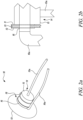
- FIG. 2a is a schematic close-up perspective view of the electrode structure of the inflatable probe 10 shown in FIGS. 1a, 1b and 1c , more particularly the portion on and around the sealing plug 14 of the probe.
- the sealing plug 14 is used to maintain the volume of fluid within the balloon 13.
- the fluid may be a gas such as air, nitrogen, or a gas lighter than air such as helium.
- the sealing plug 14, which includes the first seal electrode 15, may be made from a solid material, e.g. a metal.
- the second seal electrode 16 may be provided on the sealing plug 14.
- the second seal electrode 16 may be formed on a clip that also has a purpose to keep the balloon 13 attached to the sealing plug 14.
- the clip may be formed of any suitable material, e.g.
- the second seal electrode 16 for contacting the outer electrode 12 on the balloon 13 is typically made from a solid material, e.g. a metal such as copper, which may be a copper strip.
- a solid material e.g. a metal such as copper, which may be a copper strip.
- FIG. 2b presents a close-up of the electrical connections within the inflatable probe 10.
- the balloon 13 is shown with the inner electrode 21 mounted on the inner surface of the balloon 13 and the outer electrode 22 mounted on the outer surface of the balloon 13.
- the sealing plug 14 with the first seal electrode 15 is shown abutting the inner electrode 11 of the balloon 13.
- the clip containing the second seal electrode 16 is shown contacting the outer electrode 12.
- the first wire 15a and the second wire 17 are shown to connect with the first seal electrode 15 and the second seal electrode 22 respectively.
- the first wire 15a is the negative wire and the second wire 16a is the positive wire.
- the use of the clip for the second seal electrode 16 is beneficial as it imparts a force onto the balloon 13 and maintains the contact between the first and second seal electrodes and the inner and outer electrodes that are on the balloon 13.
- the sealing plug 14 may also have a conduit attached that allows for the inflation and deflation of the balloon at appropriate times.
- FIG. 3 is a schematic perspective view of a second embodiment of an inflatable probe 20 of the present invention.
- the balloon 23 is shown having a plurality of outer electrodes 21 positioned around the outer/external surface of the balloon 23.
- Each outer electrode 21 is separated from the neighbouring outer electrode 21 by a non-conducting area 22, which area is not covered with the electrode material.
- the position of the inner electrodes (not shown) on the inner/internal surface of the balloon 23 corresponds with the position of the outer electrodes, i.e. they are located on the opposing surface of the balloon 23.
- the sealing plug 24 has a number of first seal electrodes that connect with the positions of the inner electrodes. Each of these electrodes may have their voltage supplied by its own wire.
- the electrodes may have the voltage supplied through a single wire or they may be paired up to reduce the number of wires.
- the number of second seal electrodes on the sealing system, whether on the plug, clip or other sealing mechanism will be the same as the number of outer electrodes 21. Each of these are solid electrodes which pair with the outer electrodes. Similar to the first seal electrodes the second seal electrodes may be supplied by any suitable number of wires from a single wire, electrodes matched in groups to each electrode having its own wire.
- a tool 29 At the head of the probe is shown a tool 29.
- the tool 29 is a complementary metal-oxide semiconductor (CMOS) chip housed in a sensor head for digitally imaging components for non-destructive evaluation.
- CMOS complementary metal-oxide semiconductor
- the tool 29 may be any suitable inspection tool or sensing device.
- the tool 19 may be a charge-coupled device (CCD) or complementary metal-oxide semiconductor (CMOS) chip for component inspection including non-destructive evaluation, or a Hall effect sensor for assessing magnetic field quality, or a grabbing implement for removal of foreign object damage.
- CCD charge-coupled device
- CMOS complementary metal-oxide semiconductor
- the response from the tool at the tip of the inflatable probe may be transmitted via electrical wires, optical fibres, or wireless methods such as Bluetooth ® or Wi-Fi TM to the outside of the complex component under investigation.
- the balloon probe works by controlling the voltage to the electrodes so that the probe is able to move within a confined space to a point to sense or probe the system.
- the balloon probe can crawl through the space, with more than one electrode pair the balloon can walk by expanding one electrode area whilst maintaining the other at the same length and repeating for the other electrode pair.
- the increase in the number of electrode pairs also increases the complexity of the system.
- the probe can be inserted into the component to be inspected in an inflated or non-inflated state depending upon the size of the aperture.
- the pressure within the balloon may be controlled by the addition or removal of a fluid. This allows the probe to either be able to slide through a gap with minimal contact with the walls or to crawl into a space if the balloon cannot be slid into the appropriate position.
- the balloon may be inflated so that contact with the component is maintained and inspection using the probe can take place. Although, this is described as slid, it may also apply to be floated into position if the fluid used is lighter than air. Changing the fluid as the balloon probe moves within the complex environment can assist the balloon to move through more complex environments.
- FIG. 4 presents a flow chart at the operation of the probe of the present invention in a method 30 of testing a component.
- the device is inserted into the working space.
- Access to the workspace may be through an access port, like a borescope port or similar, or the casing of the complex component may be removed or if there is small external access then the probe may be inserted through that access.
- the probe With the probe inside the complex component the probe can be moved and positioned to a point that is of interest in Step 32.
- the number of electrode pairs on the balloon will determine in which planes it is possible to move the probe. In the case of a single electrode pair the probe will only be able to move in a single plane.
- Step 33 the testing using the sensor takes place.
- the testing may be to inspect for degradation of components or inclusion of foreign object debris in the electrical machine, or to non-visually assess the health of the asset such as through a Hall effect sensor to study the magnetic field quality.
- the balloon may be inflated to fill the cavity/volume that is being inspected. Inflation of the balloon may help to position the sensor against the size of the component within the cavity/volume.
- the balloon may be moved to a second location. This may be done by moving the device using any cables.
- controlled voltage may be applied to the inner and outer electrodes on the balloon. By applying the controlled voltage allows the balloon to move itself within the space by crawling its way along at least one of the surfaces of the cavity/volume.
- the sensor may perform more tests to build up a map or an image of the desired properties of the scan area of the component.
- the balloon probe can be removed from the component - Step 34.
- the balloon may be inflated or deflated as appropriate and the electrodes activated if required so that the probe is able to crawl out of the area and then removed through the insertion hole.
- the system may also comprise more than one balloons covered with their electrodes arranged within the system.
- the balloons may be arranged in parallel.
- the plurality of balloons may be as described above.
- Each balloon may have its own sealing plug or may have a single plug.
- the electrode pairs on the balloons may be able coupled or may each be individually addressable. The presence of a plurality of linked balloons, allows for the structure to move in a controlled way.
Landscapes
- Physics & Mathematics (AREA)
- General Physics & Mathematics (AREA)
- Investigating Or Analyzing Materials By The Use Of Electric Means (AREA)
Abstract
Description
- The present invention relates to an inflatable probe for testing a component. In particular, the invention relates to an inflatable probe in the form of a dielectric elastomer balloon that is able to be deformed to position itself within a complex system with confined spaces, e.g. within electrical equipment such as an electrical motor.
- Complex systems are used in a number of areas of technology. They are complex in that they include both moving and static parts. In power generation, complex systems include turbines and engines. Electrical equipment is being more commonly used in power generation systems. Part of the reason for this is that engineers are looking for ways of reducing emissions of carbon dioxide; this is especially true in propulsion systems where fossil fuel-based combustion engines are being replaced with electrical motors connected to battery packs.
- Electrical power for vehicular systems is seen to be a greater part of future designs as the technology develops. However, one of the issues with using electrical power, rather than the combustion of fossil fuels, is that electrical power requires new methods to test, probe and repair electrical motors. This is because gaps between components in electrical motors tend to be much smaller than they are in combustion engines. Furthermore, many other systems, such as nuclear power, oil and gas production and telecoms systems have complex systems that are located within confined spaces. Consequently, the requirements for in situ repairs are much more complex as the classical tools that have been used for testing and repairing older systems are often not suitable for these complex systems.
- In the electrical field for example, one area in which there can be problems is in the detecting, monitoring and repairing of faults on or near a rotor or a stator. Conventional borescope and robotic inspection devices are often too large to fit in the gaps between components.
- There is therefore a need for new robotics systems that can deliver a robotic probe to a required area within a complex system, e.g. an electrical motor, to perform a test or repair and if required to move a probe or tool within a confined space to effect that test or repair, without damaging other components of the system, e.g. rotors, stators, windings or contacts or wires within the system. In other words, new designs for robotics need to be developed to overcome the limitations of conventional tools for testing and repairing machinery.
- In a first aspect there is provided an inflatable probe for testing a component, the probe comprising: a balloon formed of a dielectric material, the balloon having a neck and at least one electrode pair comprising an inner electrode and an outer electrode, the inner electrode being positioned on an internal surface of the balloon and the outer electrode being positioned on an external surface of the balloon; a sealing plug that forms an air tight seal with the neck of the balloon to retain a fluid within the balloon, the sealing plug at least having a seal electrode to connect to the inner electrode within the balloon, the sealing plug supporting a first wire to connect to a first seal electrode; and at least one tool that is connected to the balloon .
- In some embodiments a second seal electrode are provided around the external surface of the balloon and the sealing plug, so as to seal the balloon against the sealing plug, and the second seal electrode is provided with an electrical contact to connect to the outer electrode.
- In some embodiments each inner electrode and each outer electrode are flexible electrodes.
- In some embodiments each internal electrode is formed of at least one of graphene, carbon nanotubes, and metallic nanotubes.
- In some embodiments there may be from 2 to 12 pairs of inner electrodes and outer electrodes.
- In some embodiments there are a plurality of parallel arranged inflatable balloons each with separate pairs of inner electrodes and outer electrodes to enable positioning of the sensor relative to the component of interest.
- In some embodiments the at least one tool is one or more of a charge-coupled device, a complementary metal-oxide semiconductor chip, a Hall effect sensor, and a grabbing implement.
- In some embodiments the first wire that is connected to the first seal electrode and a second wire that is connected to the second seal electrode are coupled to control voltage sources to provide a controlled supply of voltage to the at least one electrode pair.
- In some embodiments a voltage supply is connected to a computer to control the supply of voltage to the at least one electrode pair, the computer also being used to receive signals from the inflatable probe.
- In some embodiments a conduit is provided in the sealing plug for supplying fluid and removing fluid from the balloon.
- In a second aspect there is provided a method of testing a component using the inflatable probe of the first aspect, the method comprising the steps of: inserting the inflatable probe of the first aspect into a workspace; moving the inflatable probe within the workspace to a component of interest for testing; testing the component using the at least one tool of the inflatable probe; and removing the inflatable probe away from the component and out of the workspace.
- In some embodiments the inflatable probe is moved by applying controlled voltages to the electrodes of the balloon.
- In some embodiments the inflatable probe is moved to different locations with respect to the component for further testing or to a different component of interest for testing before the inflatable probe is removed from the workspace.
- In some embodiments the workspace is an engine.
- The skilled person will appreciate that except where mutually exclusive, a feature described in relation to any one of the above aspects may be applied mutatis mutandis to any other aspect. Furthermore, except where mutually exclusive any feature described herein may be applied to any aspect and/or combined with any other feature described herein.
- Embodiments will now be described by way of example only, with reference to the Figures, in which:
-
FIG. 1a is a schematic perspective view of a first embodiment of an inflatable probe of the present invention; -
FIG. 1b is a schematic cut-away perspective view of the inflatable probe ofFIG.1a ; -
FIG. 1c is a schematic close-up sectional view of a portion of the probe ofFIGS. 1a and 1b to show the electrode structure; -
FIG. 2a is a schematic close-up perspective view of the electrode structure of the inflatable probe shown inFIGS. 1a, 1b and 1c ; -
FIG. 2b is close-up schematic side view of the electrode structure of the inflatable probe shown inFIGS. 1a, 1b and 1c ; -
FIG. 3 is a schematic perspective view of a second embodiment of an inflatable probe of the present invention that has a plurality of electrode pairs distributed about the balloon structure of the probe; -
FIG. 4 is a flow chart of a method of testing a component using an inflatable probe of the present invention. - The following table lists the reference numerals/signs used in the drawings with the features to which they refer:
Ref no. Feature Figure 10 Inflatable probe 1a 1b 2a 11 Inner electrode 1a 1b 1c 12 Outer electrode 1a 1b 1c 13 Balloon 1a 1b 1c 2a 2b 14 Sealing plug 1a 1b 2a 2b 15 First seal electrode 1a 1b 2a 2b 15a First wire 1a 1b 2a 2b 16 Second seal electrode (e.g. clip) 1a 2a 2b 16a Second wire 1a 2a 2b 18 Neck 1a 1b 2a 19 Tool (e.g. CCD) 1a 3 20 Inflatable probe 3 21 Outer electrode 3 22 Non-conducting area 3 23 Balloon 3 24 Sealing plug 3 25 First seal electrode 3 29 Tool (e.g. CMOS chip) 3 30 Method 4 31 Step 4 32 Step 4 33 Step 4 34 Step 4 - Aspects and embodiments of the present invention will now be discussed with reference to the accompanying figures. Further aspects and embodiments will be apparent to those skilled in the art.
-
FIG. 1a is a schematic perspective view of a first embodiment of an inflatable probe of the present invention in the form of a dielectric elastomer balloon. In this aballoon 13 is provided (e.g. coated) with a compliant inner electrode (11) and anouter electrode 12. The inner electrode is positioned on the inside surface of theballoon 13, whilst theouter electrode 12 is positioned on the outside of theballoon 13. InFIG. 1a theballoon 13 is in an inflated state and contains a fluid e.g. a liquid or air. The fluid is sealed in the balloon using asealing plug 14 that is position in aneck 18 of the probe. Thesealing plug 14 provides afirst seal electrode 15, which is used to engage with the inner electrode within theballoon 13, and has awire 15a that is connected to the first seal electrode and passes through thesealing plug 14 . The sealingplug 14 also has asecond seal electrode 16 that is positioned around the outside of the sealingplug 14. InFIG. 1 thesecond seal electrode 16 in the form of a clip that forms around theballoon 13. The clip, which may be made of any suitable material, acts both as the second seal electrode for connecting with theouter electrode 12 on the surface of theballoon 13 and a clamp to hold theballoon 13 onto the sealingplug 14.FIG. 1a shows awire 16a leading from theclip 16. Thewire 16a is used to provide a voltage to thesecond seal electrode 16 and thus to theouter electrode 12 on the balloon. Theballoon 13 itself is formed of a dielectric material, which may for example a rubber or latex or other deformable dielectric material. The inflatable probe has atool 19 located on the balloon opposite theneck 18. There may be any suitable number oftools 19 positioned about theballoon 23. Thetool 19 may be any suitable inspection tool or sensing device. For example thetool 19 may be a charge-coupled device (CCD) or complementary metal-oxide semiconductor (CMOS) chip for component inspection including non-destructive evaluation, or a Hall effect sensor for assessing magnetic field quality, or a grabbing implement for removal of foreign object damage. InFIG. 1a thetool 19 is a charge-coupled device (CCD) housed in a sensor head for digitally imaging components for non-destructive evaluation -
FIG. 1b is a schematic cut-away image of the inflatable probe shown inFIG. 1a. FIG. 1b shows theinner electrode 11 of theinflatable probe 10 that is provided (e.g. coated) on the inside surface of theballoon 13 with theouter electrode 12 being provided on the outside surface of theballoon 13. The sealingplug 14 is also shown in theneck 18 of theballoon 13. The sealingplug 14 forms an airtight seal with the deformable dielectric material of theballoon 13. The first seal electrode is used to supply the voltage to theinner electrode 11 on the inner surface of theballoon 13 whilst thesecond seal electrode 16 provides the voltage to theouter electrode 12 on the outer surface of the balloon. -
FIG. 1c is a schematic close-up view of the electrode structure of the probe ofFIGS. 1a and 1b . Theballoon 13 is formed of a deformable dielectric material, e.g. a latex. Coating the outer/external surface of theballoon 13 is theouter electrode 12. Coating the inner/internal surface of theballoon 13 is theinner electrode 11. As theballoon 13 is formed of a deformable dielectric material, it will stretch or decrease in size depending upon whether the balloon is inflated or deflated and the electrodes must also be able to stretch and deform with the dielectric material that they are formed around. If theinner electrode 11 and theouter electrode 12 are not able to deform they may well damage or break theballoon 13. - The electrodes may be made from any suitable deformable conducting material. In particular, this may a flexible host or matrix doped with materials such as graphene, carbon nanotubes, metallic nanotubes. Such coatings may be applied as a spray with a spray gun and then heated to cure. If the electrode and dielectric material are both made of a rubber, the adhesion between them and the rubber/latex balloon will be strong. Alternatively, it may be made from another suitable conductive polymer coated onto the inner or the outer surface of the
balloon 13. Alternatively, it may be made of any other deformable electrode. The use of electrodes about a layer of flexible dielectric material means that this area of the balloon acts as an actuator. As such, the application of a voltage to the electrodes creates a pressure within the layer of flexible dielectric material and results in deformation of the shape of that layer. This deformation causes an extension/inflation or compression/deflation of the balloon. By attuning the electrode structure around the dielectric elastomer balloon allows for controlled deformation such that the actuator can be manipulated in shape. -
FIG. 2a is a schematic close-up perspective view of the electrode structure of theinflatable probe 10 shown inFIGS. 1a, 1b and 1c , more particularly the portion on and around the sealingplug 14 of the probe. The sealingplug 14 is used to maintain the volume of fluid within theballoon 13. The fluid may be a gas such as air, nitrogen, or a gas lighter than air such as helium. The sealingplug 14, which includes thefirst seal electrode 15, may be made from a solid material, e.g. a metal. Thesecond seal electrode 16 may be provided on the sealingplug 14. Alternatively, as presented inFIG. 2a thesecond seal electrode 16 may be formed on a clip that also has a purpose to keep theballoon 13 attached to the sealingplug 14. The clip may be formed of any suitable material, e.g. a metal, a plastics material or a composite material. Thesecond seal electrode 16 for contacting theouter electrode 12 on theballoon 13 is typically made from a solid material, e.g. a metal such as copper, which may be a copper strip. The advantage of using solid materials for the electrodes is that it allows for wire cables to be used, these can be easily connected to the electrodes. It also allows for easier connection with theballoon 13 that has a low surface energy. -
FIG. 2b presents a close-up of the electrical connections within theinflatable probe 10. InFIG. 2b theballoon 13 is shown with theinner electrode 21 mounted on the inner surface of theballoon 13 and theouter electrode 22 mounted on the outer surface of theballoon 13. The sealingplug 14 with thefirst seal electrode 15 is shown abutting theinner electrode 11 of theballoon 13. The clip containing thesecond seal electrode 16 is shown contacting theouter electrode 12. InFIG. 2b thefirst wire 15a and the second wire 17 are shown to connect with thefirst seal electrode 15 and thesecond seal electrode 22 respectively. In this embodiment thefirst wire 15a is the negative wire and thesecond wire 16a is the positive wire. In this case the use of the clip for thesecond seal electrode 16 is beneficial as it imparts a force onto theballoon 13 and maintains the contact between the first and second seal electrodes and the inner and outer electrodes that are on theballoon 13. The sealingplug 14 may also have a conduit attached that allows for the inflation and deflation of the balloon at appropriate times. -
FIG. 3 is a schematic perspective view of a second embodiment of aninflatable probe 20 of the present invention. In this embodiment theballoon 23 is shown having a plurality ofouter electrodes 21 positioned around the outer/external surface of theballoon 23. Eachouter electrode 21 is separated from the neighbouringouter electrode 21 by anon-conducting area 22, which area is not covered with the electrode material. The position of the inner electrodes (not shown) on the inner/internal surface of theballoon 23 corresponds with the position of the outer electrodes, i.e. they are located on the opposing surface of theballoon 23. The sealingplug 24 has a number of first seal electrodes that connect with the positions of the inner electrodes. Each of these electrodes may have their voltage supplied by its own wire. Alternatively, the electrodes may have the voltage supplied through a single wire or they may be paired up to reduce the number of wires. The number of second seal electrodes on the sealing system, whether on the plug, clip or other sealing mechanism will be the same as the number ofouter electrodes 21. Each of these are solid electrodes which pair with the outer electrodes. Similar to the first seal electrodes the second seal electrodes may be supplied by any suitable number of wires from a single wire, electrodes matched in groups to each electrode having its own wire. At the head of the probe is shown atool 29. InFIG. 3 thetool 29 is a complementary metal-oxide semiconductor (CMOS) chip housed in a sensor head for digitally imaging components for non-destructive evaluation. There may be any suitable number oftools 29 positioned about theballoon 23. Thetool 29 may be any suitable inspection tool or sensing device. For example thetool 19 may be a charge-coupled device (CCD) or complementary metal-oxide semiconductor (CMOS) chip for component inspection including non-destructive evaluation, or a Hall effect sensor for assessing magnetic field quality, or a grabbing implement for removal of foreign object damage. The response from the tool at the tip of the inflatable probe may be transmitted via electrical wires, optical fibres, or wireless methods such as Bluetooth® or Wi-Fi™ to the outside of the complex component under investigation. - By controlling the voltage to the electrodes, which are separated by the dielectric medium of the balloon, causes a deformation of the balloon about the electrode. The deformation of the balloon is a result of the forces acting upon it. When voltage is applied to the electrodes, an electric field is established within the thin dielectric layer of the balloon. The electric field causes Compressive Maxwell stress within the dielectric material of the balloon. This causes a reduction in the thickness of the dielectric material but an increase in the area of the dielectric material. Therefore, through the application of voltage it is possible to control the deformation of the balloon probe and thus allow it to move. By using a number of electrodes around the probe, the probe is able to move with a number of degrees of freedom. The balloon probe works by controlling the voltage to the electrodes so that the probe is able to move within a confined space to a point to sense or probe the system. In the case of a single electrode pair the balloon probe can crawl through the space, with more than one electrode pair the balloon can walk by expanding one electrode area whilst maintaining the other at the same length and repeating for the other electrode pair. The greater the number of electrode pairs and the more control that the system can have. However, the increase in the number of electrode pairs also increases the complexity of the system.
- The probe can be inserted into the component to be inspected in an inflated or non-inflated state depending upon the size of the aperture. Once into a space the pressure within the balloon may be controlled by the addition or removal of a fluid. This allows the probe to either be able to slide through a gap with minimal contact with the walls or to crawl into a space if the balloon cannot be slid into the appropriate position. If the balloon is slid into position the balloon may be inflated so that contact with the component is maintained and inspection using the probe can take place. Although, this is described as slid, it may also apply to be floated into position if the fluid used is lighter than air. Changing the fluid as the balloon probe moves within the complex environment can assist the balloon to move through more complex environments.
-
FIG. 4 presents a flow chart at the operation of the probe of the present invention in amethod 30 of testing a component. InStep 31 the device is inserted into the working space. Access to the workspace may be through an access port, like a borescope port or similar, or the casing of the complex component may be removed or if there is small external access then the probe may be inserted through that access. With the probe inside the complex component the probe can be moved and positioned to a point that is of interest inStep 32. The number of electrode pairs on the balloon will determine in which planes it is possible to move the probe. In the case of a single electrode pair the probe will only be able to move in a single plane. If there are more electrode pairs then the number of planes that the balloon can move in increases so that it can access more difficult to reach regions of the component. The pressure in the balloon may be changed during the positioning step. This allows the balloon to move more easily and to reach narrower and more difficult to reach parts that are not accessible by other means. InStep 33 the testing using the sensor takes place. The testing may be to inspect for degradation of components or inclusion of foreign object debris in the electrical machine, or to non-visually assess the health of the asset such as through a Hall effect sensor to study the magnetic field quality. Depending upon the nature of the tests the balloon may be inflated to fill the cavity/volume that is being inspected. Inflation of the balloon may help to position the sensor against the size of the component within the cavity/volume. Once the testing has been performed the balloon may be moved to a second location. This may be done by moving the device using any cables. Alternatively, controlled voltage may be applied to the inner and outer electrodes on the balloon. By applying the controlled voltage allows the balloon to move itself within the space by crawling its way along at least one of the surfaces of the cavity/volume. Once the balloon is moved into the second or further desired location the sensor may perform more tests to build up a map or an image of the desired properties of the scan area of the component. Once the desired number of tests have been performed within the desired area of the component the balloon probe can be removed from the component -Step 34. Depending upon the nature of the area that has been probed the balloon may be inflated or deflated as appropriate and the electrodes activated if required so that the probe is able to crawl out of the area and then removed through the insertion hole. - The system may also comprise more than one balloons covered with their electrodes arranged within the system. The balloons may be arranged in parallel. The plurality of balloons may be as described above. Each balloon may have its own sealing plug or may have a single plug. The electrode pairs on the balloons may be able coupled or may each be individually addressable. The presence of a plurality of linked balloons, allows for the structure to move in a controlled way.
- It will be understood that the invention is not limited to the embodiments above-described and various modifications and improvements can be made without departing from the concepts described herein. Except where mutually exclusive, any of the features may be employed separately or in combination with any other features and the disclosure extends to and includes all combinations and sub-combinations of one or more features described herein.
Claims (14)
- An inflatable probe (10, 20) for testing a component, the inflatable probe comprising:a balloon (13, 23) formed of a dielectric material, the balloon having a neck (18) and at least one electrode pair comprising an inner electrode (11) and an outer electrode (12), the inner electrode (11) being positioned on an internal surface of the balloon (13, 23) and the outer electrode (12) being positioned on an external surface of the balloon (13, 23);a sealing plug (14, 24) that forms an air tight seal with neck (18) of the balloon (13, 23) to retain a fluid within the balloon, the sealing plug (14, 24) at least having a seal electrode (15) to connect to the inner electrode (11) within the balloon, the sealing plug supporting a first wire (15a) to connect to a first seal electrode (15); andat least one tool (19, 29) that is connected to the balloon (13, 23).
- The inflatable probe of claim 1, wherein a second seal electrode (16) is provided around the external surface of the balloon (13, 23) and the sealing plug (14), so as to seal the balloon against the sealing plug, and the second seal electrode is provided with an electrical contact to connect to the outer electrode (12).
- The inflatable probe of claim 1 or 2, wherein each inner electrode (11) and each outer electrode (12) are flexible electrodes.
- The inflatable probe of claim 3, wherein each inner electrode (11) is formed of at least one of graphene, carbon nanotubes, and metallic nanotubes.
- The inflatable probe of any preceding claim, wherein there are from 2 to 12 pairs of inner electrodes (11) and outer electrodes (12).
- The inflatable probe of claim 5, wherein there are a plurality of parallel arranged inflatable balloons (13, 23) each with separate pairs of inner electrodes (11) and outer electrodes (12) to enable positioning of the tool (19, 29) with respect to the component.
- The inflatable probe of any preceding claim, wherein the at least one tool (19, 29) is one or more of a charge-coupled device, a complementary metal-oxide semiconductor chip, a Hall effect sensor, and a grabbing implement.
- The inflatable probe of any one of claims 2 to 7, wherein the first wire (15a) that is connected to the first seal electrode (15) and a second wire (16a) that is connected to the second seal electrode (16) are coupled to control voltage sources to provide a controlled supply of voltage to the at least one electrode pair (11, 12).
- The inflatable probe of claim 8, wherein a voltage supply is connected to a computer to control the supply of voltage to the at least one electrode pair (11, 12), the computer also being used to receive signals from the inflatable probe.
- The inflatable probe of any preceding claim, wherein a conduit is provided in the sealing plug (14, 24) for supplying fluid and removing fluid from the balloon (13, 23).
- A method of testing a component using the inflatable probe (10, 20) of any preceding claim, the method comprising the steps of:inserting the inflatable probe (10, 20) of any preceding claim into a workspace;moving the inflatable probe (10, 20) within the workspace to a component of interest for testing;testing the component using the at least one tool (19, 29) of the inflatable probe (10, 20); andremoving the inflatable probe (10, 20) away from the component and out of the workspace.
- The method of claim 11, wherein the inflatable probe (10, 20) is moved by applying controlled voltages to the electrodes (11, 12, 21) of the balloon (13, 23).
- The method of claim 11 or 12, wherein the inflatable probe (10, 20) is moved to different locations with respect to the component for further testing or to a different component of interest for testing before the inflatable probe is removed from the workspace.
- The method of any one of claims 11 to 13, where the workspace is an engine.
Applications Claiming Priority (1)
| Application Number | Priority Date | Filing Date | Title |
|---|---|---|---|
| GBGB2312987.7A GB202312987D0 (en) | 2023-08-25 | 2023-08-25 | Probe |
Publications (2)
| Publication Number | Publication Date |
|---|---|
| EP4513161A1 true EP4513161A1 (en) | 2025-02-26 |
| EP4513161B1 EP4513161B1 (en) | 2025-07-02 |
Family
ID=88237165
Family Applications (1)
| Application Number | Title | Priority Date | Filing Date |
|---|---|---|---|
| EP24191725.1A Active EP4513161B1 (en) | 2023-08-25 | 2024-07-30 | Probe |
Country Status (3)
| Country | Link |
|---|---|
| US (1) | US20250067774A1 (en) |
| EP (1) | EP4513161B1 (en) |
| GB (1) | GB202312987D0 (en) |
Citations (2)
| Publication number | Priority date | Publication date | Assignee | Title |
|---|---|---|---|---|
| US5546008A (en) * | 1994-08-11 | 1996-08-13 | General Electric Co. | Inflatable capacitance measuring device |
| US6225813B1 (en) * | 1997-06-09 | 2001-05-01 | General Electric Co. | Portable apparatus for in situ field stator bar insulation capacitance mapping |
-
2023
- 2023-08-25 GB GBGB2312987.7A patent/GB202312987D0/en not_active Ceased
-
2024
- 2024-07-30 EP EP24191725.1A patent/EP4513161B1/en active Active
- 2024-08-01 US US18/791,814 patent/US20250067774A1/en active Pending
Patent Citations (2)
| Publication number | Priority date | Publication date | Assignee | Title |
|---|---|---|---|---|
| US5546008A (en) * | 1994-08-11 | 1996-08-13 | General Electric Co. | Inflatable capacitance measuring device |
| US6225813B1 (en) * | 1997-06-09 | 2001-05-01 | General Electric Co. | Portable apparatus for in situ field stator bar insulation capacitance mapping |
Also Published As
| Publication number | Publication date |
|---|---|
| EP4513161B1 (en) | 2025-07-02 |
| GB202312987D0 (en) | 2023-10-11 |
| US20250067774A1 (en) | 2025-02-27 |
Similar Documents
| Publication | Publication Date | Title |
|---|---|---|
| JP4340815B2 (en) | Method for mapping capacitance of stator bar insulator and capacitance measuring apparatus | |
| US20250067774A1 (en) | Probe | |
| KR20050085594A (en) | Inspection method and inspection equipment | |
| CN119589582B (en) | Clamping tool for high-pressure oil pipe detection | |
| CN113977562A (en) | Compact snakelike arm for adverse circumstances | |
| KR100939733B1 (en) | Electrical performance tester of pre-molded rubber sleeve | |
| EP4056977B1 (en) | System and method for carrying out leakage tests | |
| JP2003227860A (en) | Apparatus for scan testing printed circuit board | |
| CN1576860A (en) | Insulating property test machine for insulation bearing | |
| CN113125817B (en) | Flat cable limiting plate probe composite structure | |
| JP2009198322A (en) | Method, apparatus and system for seal inspection | |
| CN111947849B (en) | A pipeline detection system based on guided wave detection | |
| JP7315498B2 (en) | Corona discharge treatment test method and test equipment | |
| JP4539530B2 (en) | Motor insulation inspection device | |
| CN115127815B (en) | Combustion chamber static test device | |
| CN222993910U (en) | Leak test sealing clamp, device and system | |
| EP4660624A1 (en) | Inspection system and method for inspecting a surface | |
| KR100461992B1 (en) | Electical High voltage testing apparatus for premolded epoxy unit | |
| CN112462106A (en) | Probe adapter and socket matching method for synchronous test or similar synchronous test | |
| EP4063070B1 (en) | Machining fixture and method of using the same | |
| CN110967407A (en) | Probe rotating device for ultrasonic detection of bolt center hole | |
| CN222087265U (en) | Dry-type leak detection device for automobile radiator | |
| CN224163768U (en) | Isolation ball gap device for closed DC superimposed impulse test system | |
| CN120847495A (en) | Surface charge measurement device and method | |
| JP2005083910A (en) | Jig for checking leakage |
Legal Events
| Date | Code | Title | Description |
|---|---|---|---|
| PUAI | Public reference made under article 153(3) epc to a published international application that has entered the european phase |
Free format text: ORIGINAL CODE: 0009012 |
|
| STAA | Information on the status of an ep patent application or granted ep patent |
Free format text: STATUS: REQUEST FOR EXAMINATION WAS MADE |
|
| 17P | Request for examination filed |
Effective date: 20250108 |
|
| AK | Designated contracting states |
Kind code of ref document: A1 Designated state(s): AL AT BE BG CH CY CZ DE DK EE ES FI FR GB GR HR HU IE IS IT LI LT LU LV MC ME MK MT NL NO PL PT RO RS SE SI SK SM TR |
|
| GRAP | Despatch of communication of intention to grant a patent |
Free format text: ORIGINAL CODE: EPIDOSNIGR1 |
|
| STAA | Information on the status of an ep patent application or granted ep patent |
Free format text: STATUS: GRANT OF PATENT IS INTENDED |
|
| GRAS | Grant fee paid |
Free format text: ORIGINAL CODE: EPIDOSNIGR3 |
|
| INTG | Intention to grant announced |
Effective date: 20250428 |
|
| GRAA | (expected) grant |
Free format text: ORIGINAL CODE: 0009210 |
|
| STAA | Information on the status of an ep patent application or granted ep patent |
Free format text: STATUS: THE PATENT HAS BEEN GRANTED |
|
| P01 | Opt-out of the competence of the unified patent court (upc) registered |
Free format text: CASE NUMBER: APP_20723/2025 Effective date: 20250430 |
|
| AK | Designated contracting states |
Kind code of ref document: B1 Designated state(s): AL AT BE BG CH CY CZ DE DK EE ES FI FR GB GR HR HU IE IS IT LI LT LU LV MC ME MK MT NL NO PL PT RO RS SE SI SK SM TR |
|
| REG | Reference to a national code |
Ref country code: GB Ref legal event code: FG4D |
|
| REG | Reference to a national code |
Ref country code: CH Ref legal event code: EP |
|
| REG | Reference to a national code |
Ref country code: DE Ref legal event code: R096 Ref document number: 602024000270 Country of ref document: DE |
|
| REG | Reference to a national code |
Ref country code: IE Ref legal event code: FG4D |
|
| PGFP | Annual fee paid to national office [announced via postgrant information from national office to epo] |
Ref country code: FR Payment date: 20250725 Year of fee payment: 2 |
|
| REG | Reference to a national code |
Ref country code: NL Ref legal event code: MP Effective date: 20250702 |
|
| PG25 | Lapsed in a contracting state [announced via postgrant information from national office to epo] |
Ref country code: PT Free format text: LAPSE BECAUSE OF FAILURE TO SUBMIT A TRANSLATION OF THE DESCRIPTION OR TO PAY THE FEE WITHIN THE PRESCRIBED TIME-LIMIT Effective date: 20251103 |
|
| PG25 | Lapsed in a contracting state [announced via postgrant information from national office to epo] |
Ref country code: NL Free format text: LAPSE BECAUSE OF FAILURE TO SUBMIT A TRANSLATION OF THE DESCRIPTION OR TO PAY THE FEE WITHIN THE PRESCRIBED TIME-LIMIT Effective date: 20250702 |
|
| REG | Reference to a national code |
Ref country code: AT Ref legal event code: MK05 Ref document number: 1809703 Country of ref document: AT Kind code of ref document: T Effective date: 20250702 |
|
| PG25 | Lapsed in a contracting state [announced via postgrant information from national office to epo] |
Ref country code: IS Free format text: LAPSE BECAUSE OF FAILURE TO SUBMIT A TRANSLATION OF THE DESCRIPTION OR TO PAY THE FEE WITHIN THE PRESCRIBED TIME-LIMIT Effective date: 20251102 |
|
| PG25 | Lapsed in a contracting state [announced via postgrant information from national office to epo] |
Ref country code: NO Free format text: LAPSE BECAUSE OF FAILURE TO SUBMIT A TRANSLATION OF THE DESCRIPTION OR TO PAY THE FEE WITHIN THE PRESCRIBED TIME-LIMIT Effective date: 20251002 |
|
| REG | Reference to a national code |
Ref country code: LT Ref legal event code: MG9D |
|
| PG25 | Lapsed in a contracting state [announced via postgrant information from national office to epo] |
Ref country code: AT Free format text: LAPSE BECAUSE OF FAILURE TO SUBMIT A TRANSLATION OF THE DESCRIPTION OR TO PAY THE FEE WITHIN THE PRESCRIBED TIME-LIMIT Effective date: 20250702 |
|
| PG25 | Lapsed in a contracting state [announced via postgrant information from national office to epo] |
Ref country code: FI Free format text: LAPSE BECAUSE OF FAILURE TO SUBMIT A TRANSLATION OF THE DESCRIPTION OR TO PAY THE FEE WITHIN THE PRESCRIBED TIME-LIMIT Effective date: 20250702 |
|
| PG25 | Lapsed in a contracting state [announced via postgrant information from national office to epo] |
Ref country code: HR Free format text: LAPSE BECAUSE OF FAILURE TO SUBMIT A TRANSLATION OF THE DESCRIPTION OR TO PAY THE FEE WITHIN THE PRESCRIBED TIME-LIMIT Effective date: 20250702 |
|
| PG25 | Lapsed in a contracting state [announced via postgrant information from national office to epo] |
Ref country code: GR Free format text: LAPSE BECAUSE OF FAILURE TO SUBMIT A TRANSLATION OF THE DESCRIPTION OR TO PAY THE FEE WITHIN THE PRESCRIBED TIME-LIMIT Effective date: 20251003 |
|
| PG25 | Lapsed in a contracting state [announced via postgrant information from national office to epo] |
Ref country code: CZ Free format text: LAPSE BECAUSE OF FAILURE TO SUBMIT A TRANSLATION OF THE DESCRIPTION OR TO PAY THE FEE WITHIN THE PRESCRIBED TIME-LIMIT Effective date: 20250702 Ref country code: SE Free format text: LAPSE BECAUSE OF FAILURE TO SUBMIT A TRANSLATION OF THE DESCRIPTION OR TO PAY THE FEE WITHIN THE PRESCRIBED TIME-LIMIT Effective date: 20250702 |
|
| PG25 | Lapsed in a contracting state [announced via postgrant information from national office to epo] |
Ref country code: LV Free format text: LAPSE BECAUSE OF FAILURE TO SUBMIT A TRANSLATION OF THE DESCRIPTION OR TO PAY THE FEE WITHIN THE PRESCRIBED TIME-LIMIT Effective date: 20250702 |
|
| PG25 | Lapsed in a contracting state [announced via postgrant information from national office to epo] |
Ref country code: PL Free format text: LAPSE BECAUSE OF FAILURE TO SUBMIT A TRANSLATION OF THE DESCRIPTION OR TO PAY THE FEE WITHIN THE PRESCRIBED TIME-LIMIT Effective date: 20250702 Ref country code: BG Free format text: LAPSE BECAUSE OF FAILURE TO SUBMIT A TRANSLATION OF THE DESCRIPTION OR TO PAY THE FEE WITHIN THE PRESCRIBED TIME-LIMIT Effective date: 20250702 |
|
| PG25 | Lapsed in a contracting state [announced via postgrant information from national office to epo] |
Ref country code: RS Free format text: LAPSE BECAUSE OF FAILURE TO SUBMIT A TRANSLATION OF THE DESCRIPTION OR TO PAY THE FEE WITHIN THE PRESCRIBED TIME-LIMIT Effective date: 20251002 |
|
| PG25 | Lapsed in a contracting state [announced via postgrant information from national office to epo] |
Ref country code: ES Free format text: LAPSE BECAUSE OF FAILURE TO SUBMIT A TRANSLATION OF THE DESCRIPTION OR TO PAY THE FEE WITHIN THE PRESCRIBED TIME-LIMIT Effective date: 20250702 |
|
| PG25 | Lapsed in a contracting state [announced via postgrant information from national office to epo] |
Ref country code: SM Free format text: LAPSE BECAUSE OF FAILURE TO SUBMIT A TRANSLATION OF THE DESCRIPTION OR TO PAY THE FEE WITHIN THE PRESCRIBED TIME-LIMIT Effective date: 20250702 |
|
| PG25 | Lapsed in a contracting state [announced via postgrant information from national office to epo] |
Ref country code: DK Free format text: LAPSE BECAUSE OF FAILURE TO SUBMIT A TRANSLATION OF THE DESCRIPTION OR TO PAY THE FEE WITHIN THE PRESCRIBED TIME-LIMIT Effective date: 20250702 |
|
| PG25 | Lapsed in a contracting state [announced via postgrant information from national office to epo] |
Ref country code: IT Free format text: LAPSE BECAUSE OF FAILURE TO SUBMIT A TRANSLATION OF THE DESCRIPTION OR TO PAY THE FEE WITHIN THE PRESCRIBED TIME-LIMIT Effective date: 20250702 |
|
| PG25 | Lapsed in a contracting state [announced via postgrant information from national office to epo] |
Ref country code: EE Free format text: LAPSE BECAUSE OF FAILURE TO SUBMIT A TRANSLATION OF THE DESCRIPTION OR TO PAY THE FEE WITHIN THE PRESCRIBED TIME-LIMIT Effective date: 20250702 Ref country code: SK Free format text: LAPSE BECAUSE OF FAILURE TO SUBMIT A TRANSLATION OF THE DESCRIPTION OR TO PAY THE FEE WITHIN THE PRESCRIBED TIME-LIMIT Effective date: 20250702 |
|
| PLBE | No opposition filed within time limit |
Free format text: ORIGINAL CODE: 0009261 |
|
| STAA | Information on the status of an ep patent application or granted ep patent |
Free format text: STATUS: NO OPPOSITION FILED WITHIN TIME LIMIT |