EP4513122A1 - Heat exchanger and air conditioning device - Google Patents
Heat exchanger and air conditioning device Download PDFInfo
- Publication number
- EP4513122A1 EP4513122A1 EP22938485.4A EP22938485A EP4513122A1 EP 4513122 A1 EP4513122 A1 EP 4513122A1 EP 22938485 A EP22938485 A EP 22938485A EP 4513122 A1 EP4513122 A1 EP 4513122A1
- Authority
- EP
- European Patent Office
- Prior art keywords
- space
- heat exchanger
- refrigerant
- inner pipe
- partition
- Prior art date
- Legal status (The legal status is an assumption and is not a legal conclusion. Google has not performed a legal analysis and makes no representation as to the accuracy of the status listed.)
- Pending
Links
Images





Classifications
-
- F—MECHANICAL ENGINEERING; LIGHTING; HEATING; WEAPONS; BLASTING
- F28—HEAT EXCHANGE IN GENERAL
- F28F—DETAILS OF HEAT-EXCHANGE AND HEAT-TRANSFER APPARATUS, OF GENERAL APPLICATION
- F28F9/00—Casings; Header boxes; Auxiliary supports for elements; Auxiliary members within casings
- F28F9/02—Header boxes; End plates
- F28F9/026—Header boxes; End plates with static flow control means, e.g. with means for uniformly distributing heat exchange media into conduits
- F28F9/027—Header boxes; End plates with static flow control means, e.g. with means for uniformly distributing heat exchange media into conduits in the form of distribution pipes
- F28F9/0273—Header boxes; End plates with static flow control means, e.g. with means for uniformly distributing heat exchange media into conduits in the form of distribution pipes with multiple holes
-
- F—MECHANICAL ENGINEERING; LIGHTING; HEATING; WEAPONS; BLASTING
- F28—HEAT EXCHANGE IN GENERAL
- F28D—HEAT-EXCHANGE APPARATUS, NOT PROVIDED FOR IN ANOTHER SUBCLASS, IN WHICH THE HEAT-EXCHANGE MEDIA DO NOT COME INTO DIRECT CONTACT
- F28D1/00—Heat-exchange apparatus having stationary conduit assemblies for one heat-exchange medium only, the media being in contact with different sides of the conduit wall, in which the other heat-exchange medium is a large body of fluid, e.g. domestic or motor car radiators
- F28D1/02—Heat-exchange apparatus having stationary conduit assemblies for one heat-exchange medium only, the media being in contact with different sides of the conduit wall, in which the other heat-exchange medium is a large body of fluid, e.g. domestic or motor car radiators with heat-exchange conduits immersed in the body of fluid
- F28D1/04—Heat-exchange apparatus having stationary conduit assemblies for one heat-exchange medium only, the media being in contact with different sides of the conduit wall, in which the other heat-exchange medium is a large body of fluid, e.g. domestic or motor car radiators with heat-exchange conduits immersed in the body of fluid with tubular conduits
- F28D1/053—Heat-exchange apparatus having stationary conduit assemblies for one heat-exchange medium only, the media being in contact with different sides of the conduit wall, in which the other heat-exchange medium is a large body of fluid, e.g. domestic or motor car radiators with heat-exchange conduits immersed in the body of fluid with tubular conduits the conduits being straight
- F28D1/05316—Assemblies of conduits connected to common headers, e.g. core type radiators
-
- F—MECHANICAL ENGINEERING; LIGHTING; HEATING; WEAPONS; BLASTING
- F28—HEAT EXCHANGE IN GENERAL
- F28D—HEAT-EXCHANGE APPARATUS, NOT PROVIDED FOR IN ANOTHER SUBCLASS, IN WHICH THE HEAT-EXCHANGE MEDIA DO NOT COME INTO DIRECT CONTACT
- F28D1/00—Heat-exchange apparatus having stationary conduit assemblies for one heat-exchange medium only, the media being in contact with different sides of the conduit wall, in which the other heat-exchange medium is a large body of fluid, e.g. domestic or motor car radiators
- F28D1/02—Heat-exchange apparatus having stationary conduit assemblies for one heat-exchange medium only, the media being in contact with different sides of the conduit wall, in which the other heat-exchange medium is a large body of fluid, e.g. domestic or motor car radiators with heat-exchange conduits immersed in the body of fluid
- F28D1/04—Heat-exchange apparatus having stationary conduit assemblies for one heat-exchange medium only, the media being in contact with different sides of the conduit wall, in which the other heat-exchange medium is a large body of fluid, e.g. domestic or motor car radiators with heat-exchange conduits immersed in the body of fluid with tubular conduits
- F28D1/053—Heat-exchange apparatus having stationary conduit assemblies for one heat-exchange medium only, the media being in contact with different sides of the conduit wall, in which the other heat-exchange medium is a large body of fluid, e.g. domestic or motor car radiators with heat-exchange conduits immersed in the body of fluid with tubular conduits the conduits being straight
- F28D1/0535—Heat-exchange apparatus having stationary conduit assemblies for one heat-exchange medium only, the media being in contact with different sides of the conduit wall, in which the other heat-exchange medium is a large body of fluid, e.g. domestic or motor car radiators with heat-exchange conduits immersed in the body of fluid with tubular conduits the conduits being straight the conduits having a non-circular cross-section
- F28D1/05366—Assemblies of conduits connected to common headers, e.g. core type radiators
-
- F—MECHANICAL ENGINEERING; LIGHTING; HEATING; WEAPONS; BLASTING
- F28—HEAT EXCHANGE IN GENERAL
- F28F—DETAILS OF HEAT-EXCHANGE AND HEAT-TRANSFER APPARATUS, OF GENERAL APPLICATION
- F28F1/00—Tubular elements; Assemblies of tubular elements
- F28F1/10—Tubular elements and assemblies thereof with means for increasing heat-transfer area, e.g. with fins, with projections, with recesses
- F28F1/12—Tubular elements and assemblies thereof with means for increasing heat-transfer area, e.g. with fins, with projections, with recesses the means being only outside the tubular element
- F28F1/126—Tubular elements and assemblies thereof with means for increasing heat-transfer area, e.g. with fins, with projections, with recesses the means being only outside the tubular element consisting of zig-zag shaped fins
Definitions
- the present invention relates to a heat exchanger including a double-pipe refrigerant distributer and to an air-conditioning apparatus including the heat exchanger.
- Patent Literature 1 Japanese Unexamined Patent Application Publication JP 2012- 2 475 A
- the heat exchanger including the known double-pipe refrigerant distributer may experience a deterioration of the heat-exchange performance thereof when the liquid refrigerant component of the two-phase gas-liquid refrigerant is unevenly distributed to the heat transfer tubes, depending on the condition of the two-phase gas-liquid refrigerant flowing inside the inner pipe. Such condition may occur where the liquid refrigerant component of the two-phase gas-liquid refrigerant flows unevenly inside the inner pipe.
- the present invention has been conceived in view of the above circumstances, and a first object of the present invention is to provide a heat exchanger configured to exhibit more even distribution of the liquid refrigerant component of the two-phase gas-liquid refrigerant to the heat transfer tubes than in the known art.
- a second object of the present invention is to provide an air-conditioning apparatus including such a heat exchanger.
- a heat exchanger of one embodiment of the present invention includes a plurality of heat transfer tubes, an outer pipe having a plurality of connection parts that are arranged at intervals in a longitudinal direction and to each of which a corresponding one of the plurality of heat transfer tubes is connected, an inner pipe provided inside the outer pipe and having a plurality of first orifices at a periphery, and a first partition having a first through-hole in which the inner pipe is fitted, the first partition separating an inside of the outer pipe into a main space and a first space.
- the main space is a space with which the plurality of first orifices and the plurality of connection parts communicate.
- the first space communicates with none of the plurality of first orifices and the plurality of connection parts and is a space with which an opening provided at one end of the inner pipe communicates, the one end being a first end.
- Refrigerant supplied into the first space flows into an inside of the inner pipe, the plurality of first orifices, the main space, the plurality of connection parts, and then the plurality of heat transfer tubes.
- a gas refrigerant component and a liquid refrigerant component of a two-phase gas-liquid refrigerant flowing in the first space are mixed together in the first space.
- the two-phase gas-liquid refrigerant with the gas refrigerant component and the liquid refrigerant component thereof thus mixed together is distributed to the plurality of heat transfer tubes after flowing through the inside of the inner pipe, the first orifices, the main space, and the connection parts of the outer pipe.
- the liquid refrigerant component of the two-phase gas-liquid refrigerant is distributed more evenly to the heat transfer tubes than in the known art.
- Embodiments exemplifying the heat exchanger according to the present invention will now be described with reference to the drawings.
- Embodiment 1 an example of the air-conditioning apparatus according to the present invention will be described with reference to relevant drawings.
- like elements are denoted by like reference signs. Redundant description of the embodiments is omitted, if not necessary.
- the heat exchanger and the air-conditioning apparatus according to the present invention may include any combination of combinable features to be described in the following embodiments.
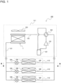
- FIG. 1 is a refrigerant circuit diagram illustrating an air-conditioning apparatus according to Embodiment 1.
- the air-conditioning apparatus, 100 includes a heat exchanger 1 according to Embodiment 1.
- the heat exchanger 1 is employed as an outdoor heat exchanger.
- the air-conditioning apparatus 100 includes a compressor 101; an indoor heat exchanger 105, which serves as a condenser in a heating operation; an expansion valve 104, which is configured to expand refrigerant discharged from the condenser; and the heat exchanger 1, which is employed as an outdoor heat exchanger that serves as an evaporator in the heating operation.
- the compressor 101, the indoor heat exchanger 105, the expansion valve 104, and the heat exchanger 1 employed as an outdoor heat exchanger are connected to one another by refrigerant pipes, whereby a refrigerant circuit is formed for refrigerant to circulate therethrough.
- refrigerant pipe 122 one of the refrigerant pipes that connects between the compressor 101 and the heat exchanger 1
- refrigerant pipe 121 another one of the refrigerant pipes that connects between the expansion valve 104 and the heat exchanger 1 is denoted as a refrigerant pipe 121.
- the refrigerant circuit of the air-conditioning apparatus 100 according to Embodiment 1 further includes an accumulator 107, which is configured to accumulate excess refrigerant and is provided on the suction side of the compressor 101.
- the air-conditioning apparatus 100 according to Embodiment 1 is also capable of performing a cooling operation.
- the air-conditioning apparatus 100 includes a four-way valve 102.
- the four-way valve 102 is configured to switch the heat exchangers to be connected to the discharge port of the compressor 101 and to switch the heat exchangers to be connected to the suction port of the compressor 101.
- the indoor heat exchanger 105 serves as an evaporator
- the heat exchanger 1 employed as an outdoor heat exchanger serves as a condenser.
- the above elements forming the refrigerant circuit of the air-conditioning apparatus 100 are each included in either an outdoor unit 111 or an indoor unit 112. Specifically, the compressor 101, the four-way valve 102, the heat exchanger 1 employed as an outdoor heat exchanger, and the accumulator 107 are included in the outdoor unit 111. The indoor heat exchanger 105 and the expansion valve 104 are included in the indoor unit 112. The outdoor unit 111 further includes a fan 103, which is configured to supply outdoor air to the heat exchanger 1 employed as an outdoor heat exchanger.
- the indoor unit 112 further includes a fan 106, which is configured to supply indoor air to the indoor heat exchanger 105.
- the air-conditioning apparatus 100 includes at least one indoor unit 112.
- the air-conditioning apparatus 100 exemplified in FIG. 1 includes three indoor units 112. If the air-conditioning apparatus 100 includes a plurality of indoor units 112, the indoor units 112 are, for example, connected in parallel with each other to the outdoor unit 111.
- refrigerant circulates as represented by broken-line arrows in FIG. 1 .
- the four-way valve 102 is switched to establish a passageway represented by broken lines in FIG. 1 .
- the discharge port of the compressor 101 is connected to the indoor heat exchanger 105, and the suction port of the compressor 101 is connected to the heat exchanger 1 employed as an outdoor heat exchanger.
- the indoor heat exchanger 105 serves as a condenser
- the heat exchanger 1 employed as an outdoor heat exchanger serves as an evaporator.
- a gas refrigerant compressed by the compressor 101 to have a high temperature and a high pressure is discharged from the compressor 101 and flows into the indoor heat exchanger 105.
- the high-temperature high-pressure gas refrigerant flowing in the indoor heat exchanger 105 condenses while rejecting heat to the indoor air supplied from the fan 106, thereby turning into a high-pressure liquid refrigerant, which is discharged from the indoor heat exchanger 105. In this process, the indoor air is heated.
- the high-pressure liquid refrigerant discharged from the indoor heat exchanger 105 flows into the expansion valve 104.
- the high-pressure liquid refrigerant flowing in the expansion valve 104 is expanded by the expansion valve 104, thereby turning into a low-temperature low-pressure two-phase gas-liquid refrigerant, which is discharged from the expansion valve 104.
- the low-temperature low-pressure two-phase gas-liquid refrigerant discharged from the expansion valve 104 flows through the refrigerant pipe 121 into the heat exchanger 1 employed as an outdoor heat exchanger.
- the low-temperature low-pressure two-phase gas-liquid refrigerant flowing in the heat exchanger 1 employed as an outdoor heat exchanger evaporates by receiving heat from the outdoor air supplied from the fan 103, thereby turning into a low-pressure gas refrigerant, which is discharged from the heat exchanger 1 employed as an outdoor heat exchanger.
- the low-pressure gas refrigerant discharged from the heat exchanger 1 employed as an outdoor heat exchanger flows through the refrigerant pipe 122 and is suctioned into the compressor 101.
- the low-pressure gas refrigerant suctioned into the compressor 101 is compressed by the compressor 101, thereby turning into a high-temperature high-pressure gas refrigerant.
- the high-temperature high-pressure gas refrigerant is discharged from the compressor 101 again.
- refrigerant circulates as represented by solid-line arrows in FIG. 1 .
- the four-way valve 102 is switched to establish a passageway represented by solid lines in FIG. 1 .
- the discharge port of the compressor 101 is connected to the heat exchanger 1 employed as an outdoor heat exchanger, and the suction port of the compressor 101 is connected to the indoor heat exchanger 105. That is, the heat exchanger 1 employed as an outdoor heat exchanger serves as a condenser, whereas the indoor heat exchanger 105 serves as an evaporator.
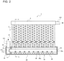
- the heat exchanger 1 includes a refrigerant distributer 10, a plurality of heat transfer tubes 2, a plurality of fins 3, and a merging pipe 4. With the heat exchanger 1 installed in the air-conditioning apparatus 100, the refrigerant distributer 10 is laid out in, for example, the horizontal direction. The plurality of heat transfer tubes 2 are arranged side by side at intervals. One end of each of the heat transfer tubes 2 is connected to the refrigerant distributer 10.
- the refrigerant flowing from the outside toward the heat exchanger 1 first flows into the refrigerant distributer 10.
- the refrigerant flowing in the refrigerant distributer 10 is distributed in portions to the heat transfer tubes 2, and the refrigerant portions flow into the respective heat transfer tubes 2.
- the refrigerant portions flowing in the heat transfer tubes 2 exchange heat with air through the heat transfer tubes 2 and the fins 3.
- the refrigerant portions are then discharged from the heat transfer tubes 2 and are collected together by the merging pipe 4.
- the collected refrigerant is discharged from the merging pipe 4 to the outside of the heat exchanger 1.
- the refrigerant flowing from the outside toward the heat exchanger 1 first flows into the merging pipe 4.
- the refrigerant flowing in the merging pipe 4 is distributed in portions to the heat transfer tubes 2, and the refrigerant portions flow into the respective heat transfer tubes 2.
- the refrigerant portions flowing in the heat transfer tubes 2 exchange heat with air through the heat transfer tubes 2 and the fins 3.
- the refrigerant portions are then discharged from the heat transfer tubes 2 and are collected together by the refrigerant distributer 10.
- the collected refrigerant is discharged from the refrigerant distributer 10 to the outside of the heat exchanger 1. Therefore, the refrigerant pipe 121 is connected to the refrigerant distributer 10, and the refrigerant pipe 122 is connected to the merging pipe 4.
- the heat exchanger 1 When the heat exchanger 1 is used as an evaporator, as described above, the refrigerant flowing from the outside into the refrigerant distributer 10 is distributed to the heat transfer tubes 2. That is, the refrigerant distributer 10 distributes a two-phase gas-liquid refrigerant to the heat transfer tubes 2. To distribute the two-phase gas-liquid refrigerant to the heat transfer tubes 2 while reducing the probability of deterioration in the heat-exchange performance of the heat exchanger 1, it is important to evenly distribute the liquid refrigerant component of the two-phase gas-liquid refrigerant to the heat transfer tubes 2.
- the heat exchanger 1 according to Embodiment 1 employs the refrigerant distributer 10 configured as illustrated in FIG. 2 .
- the refrigerant distributer 10 has a double-pipe structure and includes an outer pipe 20, an inner pipe 30, and a first partition 11.
- the outer pipe 20 is a pipe member with the both ends thereof closed.
- the outer pipe 20 has a plurality of connection parts 21, which are arranged at intervals in the longitudinal direction of the outer pipe 20 and to each of which a corresponding one of the heat transfer tubes 2 is connected. That is, the plurality of heat transfer tubes 2 are arranged side by side at intervals in the longitudinal direction of the outer pipe 20.
- the longitudinal direction of the outer pipe 20 refers to the direction in which the outer pipe 20 extends and is also regarded as the axial direction of the outer pipe 20.
- the left-right direction in the plane of the page matches with the longitudinal direction of the outer pipe 20.
- the outer pipe 20 may be bent at least in part thereof.
- the longitudinal direction of such an outer pipe 20 at any given point is regarded as the axial direction of the outer pipe 20 at that given point.
- the inner pipe 30 is a pipe member with at least one end thereof open.
- the one end is referred to as a first end 31.
- the inner pipe 30 is a pipe member having an opening 31a at least at the first end 31 thereof.
- the inner pipe 30 is a pipe member with the both ends thereof open. That is, the inner pipe 30 according to Embodiment 1 is open also at the other end, which is a second end 32 and is located opposite the first end 31.
- the inner pipe 30 according to Embodiment 1 has an opening 32a at the second end 32 thereof.
- the inner pipe 30 is provided inside the outer pipe 20. With the inner pipe 30 placed inside the outer pipe 20, the opening 31a at the first end 31 communicates with the space inside the outer pipe 20. Furthermore, with the inner pipe 30 placed inside the outer pipe 20, the opening 32a at the second end 32 is closed by an end wall of the outer pipe 20.
- the inner pipe 30 has at the periphery thereof a plurality of first orifices 30a, which are also referred to as refrigerant discharge holes. The plurality of first orifices 30a are arranged at intervals in the axial direction of the inner pipe 30.
- the two-phase gas-liquid refrigerant flowing inside the inner pipe 30 is discharged through the plurality of first orifices 30a to a space provided between the outer peripheral surface of the inner pipe 30 and the inner peripheral surface of the outer pipe 20, which will be described in detail separately below.
- the two-phase gas-liquid refrigerant discharged to the space between the outer peripheral surface of the inner pipe 30 and the inner peripheral surface of the outer pipe 20 flows through the connection parts 21 of the outer pipe 20 into the heat transfer tubes 2.
- the plurality of first orifices 30a may preferably be located as illustrated in FIG. 2 , although the locations of the plurality of first orifices 30a are not limited. Specifically, the first orifices 30a may each preferably be located between corresponding adjacent two of the heat transfer tubes 2 in the axial direction of the inner pipe 30.
- the gas refrigerant component and the liquid refrigerant component of the two-phase gas-liquid refrigerant discharged into the space between the outer peripheral surface of the inner pipe 30 and the inner peripheral surface of the outer pipe 20 are mixed together in the space in a better way before flowing into the heat transfer tubes 2 than in an arrangement where the first orifices 30a are located vertically below the respective heat transfer tubes 2. That is, the arrangement of the first orifices 30a that is illustrated in FIG. 2 realizes more even distribution of the liquid refrigerant component of the two-phase gas-liquid refrigerant to the heat transfer tubes 2.
- the inner pipe 30 is held at positions close to the both ends thereof, whereby the axis of the inner pipe 30 is prevented from incline significantly relative to the axis of the outer pipe 20.
- Such a configuration realizes more even distribution of the liquid refrigerant component of the two-phase gas-liquid refrigerant to the heat transfer tubes 2.
- the refrigerant flowing from the outside toward the refrigerant distributer 10 is temporarily supplied into the first space 41.
- the refrigerant supplied from the outside into the first space 41 flows into the plurality of heat transfer tubes 2 after flowing through the inside of the inner pipe 30, the plurality of first orifices 30a, the main space 40, and the plurality of connection parts 21.
- the outer pipe 20 according to Embodiment 1 has a connection part 22, which communicates with the first space 41.
- the refrigerant pipe 121 is connected to the connection part 22. Therefore, when the heat exchanger 1 is used as an evaporator, the two-phase gas-liquid refrigerant is supplied into the first space 41 of the refrigerant distributer 10 through the refrigerant pipe 121.
- the way of connection of the refrigerant pipe 121 to the outer pipe 20 may preferably be as illustrated in FIG. 2 .
- the refrigerant pipe 121 connected to the outer pipe 20 may preferably extend in the direction in which the heat transfer tubes 2 extend. Such a way of connection of the refrigerant pipe 121 to the outer pipe 20 reduces the length of the space occupied by the refrigerant pipe 121 in the direction in which the plurality of heat transfer tubes 2 are arranged side by side.
- the above way of connection of the refrigerant pipe 121 to the outer pipe 20 allows an increased number of heat transfer tubes 2 to be arranged side by side in the space of the air-conditioning apparatus 100 that is provided for the installation of the heat exchanger 1 and the refrigerant pipe 121. Accordingly, the above way of connection of the refrigerant pipe 121 to the outer pipe 20 increases the installability of the heat transfer tubes 2 in the heat exchanger 1.
- Some known heat exchangers include double-pipe refrigerant distributers, aiming to realize even distribution of the liquid refrigerant component of the two-phase gas-liquid refrigerant to the heat transfer tubes.
- Such a known double-pipe refrigerant distributer does not have the first space 41 inside the outer pipe thereof, allowing the refrigerant on the outside to flow directly into the inner pipe. Therefore, the heat exchanger including the known double-pipe refrigerant distributer may experience a deterioration of the heat-exchange performance thereof when the liquid refrigerant component of the two-phase gas-liquid refrigerant is unevenly distributed to the heat transfer tubes, depending on the condition of the two-phase gas-liquid refrigerant flowing inside the inner pipe. Such condition may occur where the distribution of the liquid refrigerant component of the two-phase gas-liquid refrigerant flows unevenly inside the inner pipe.
- the liquid refrigerant component of the two-phase gas-liquid refrigerant is prevented from flowing unevenly inside the inner pipe 30, realizing a stable flow of the two-phase gas-liquid refrigerant in the inner pipe 30.
- the liquid refrigerant component of the two-phase gas-liquid refrigerant is distributed more evenly to the heat transfer tubes 2 than in the known art.
- the main space 40 is a space with which the plurality of first orifices 30a and the plurality of connection parts 21 communicate.
- the first space 41 communicates with none of the plurality of first orifices 30a and the plurality of connection parts 21.
- the first space 41 is a space with which the opening 31a provided at the first end 31 of the inner pipe 30 communicates.
- the refrigerant supplied into the first space 41 flows into the plurality of heat transfer tubes 2 after flowing through the inside of the inner pipe 30, the plurality of first orifices 30a, the main space 40, and the plurality of connection parts 21.
- the liquid refrigerant component of the two-phase gas-liquid refrigerant is prevented from flowing unevenly inside the inner pipe 30, realizing a stable flow of the two-phase gas-liquid refrigerant in the inner pipe 30.
- the liquid refrigerant component of the two-phase gas-liquid refrigerant is distributed more evenly to the heat transfer tubes 2 than in the known art.
- the heat exchanger 1 is employed as an outdoor heat exchanger of the air-conditioning apparatus 100, the heat exchanger 1 is not limited thereto.
- the heat exchanger 1 may alternatively be employed as the indoor heat exchanger 105 of the air-conditioning apparatus 100.
- the heat exchanger 1 may be applied to both the outdoor heat exchanger and the indoor heat exchanger 105 of the air-conditioning apparatus 100.
- Embodiment 2 if a second space 42 is further provided inside the outer pipe 20 of the refrigerant distributer 10, the liquid refrigerant component of the two-phase gas-liquid refrigerant is distributed further more evenly to the heat transfer tubes 2.
- Features that are not described in Embodiment 2 are the same as those described in Embodiment 1.
- the heat exchanger 1 according to Embodiment 2 includes a second partition 12, which is provided in the refrigerant distributer 10.
- the second partition 12 is provided inside the outer pipe 20.
- the second partition 12 has a second through-hole 12a.
- a portion of the inner pipe 30 that is close to the second end 32 is fitted in the second through-hole 12a of the second partition 12.
- the portion of the inner pipe 30 that is close to the second end 32 is held by the second partition 12.
- the second partition 12 closes the space provided between the outer peripheral surface of the inner pipe 30 and the inner peripheral surface of the outer pipe 20. Hence, the inside of the outer pipe 20 is separated by the second partition 12 into the main space 40 and the second space 42.
- the main space 40 is a space with which the plurality of first orifices 30a and the plurality of connection parts 21 communicate.
- the second space 42 communicates with none of the plurality of first orifices 30a and the plurality of connection parts 21.
- the second space 42 is a space with which the opening 32a provided at the second end 32 of the inner pipe 30 communicates.
- the second space 42 has a larger area than the space inside the inner pipe 30 in a section taken perpendicularly to the axis of the inner pipe 30.
- the two-phase gas-liquid refrigerant flowing inside the inner pipe 30 flows into the second space 42 through the opening 32a provided at the second end 32 and strikes the end wall of the outer pipe 20.
- the liquid refrigerant component of the two-phase gas-liquid refrigerant is gathered in the second space 42.
- the second space 42 is provided inside the outer pipe 20 of the refrigerant distributer 10, the liquid refrigerant component of the two-phase gas-liquid refrigerant is prevented from being distributed by a greater amount to those of the plurality of first orifices 30a that are located closer to the second end 32. That is, providing the second space 42 inside the outer pipe 20 of the refrigerant distributer 10 realizes further more even distribution of the liquid refrigerant component of the two-phase gas-liquid refrigerant to the heat transfer tubes 2.
- the present inventors have elucidated the above mechanism of how the second space 42 provided inside the outer pipe 20 improves the refrigerant distribution, through an experiment of visualizing the flow behavior of the two-phase gas-liquid refrigerant in the refrigerant distributer 10. Now, the mechanism of improvement in the refrigerant distribution that has been demonstrated by the present inventors will be described with reference to FIGS. 5 and 6 .
- FIG. 5 is a sectional view of a refrigerant distributer according to Comparative Example.
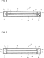
- FIG. 6 is a sectional view of the refrigerant distributer according to Embodiment 2.
- elements that are the same as those of the refrigerant distributer 10 according to Embodiment 2 are denoted by same reference signs as used for the refrigerant distributer 10 according to Embodiment 2.
- the refrigerant distributer 210 according to Comparative Example has no second space 42 inside the outer pipe 20. Therefore, in the refrigerant distributer 210 according to Comparative Example, the opening 32a provided at the second end 32 of the inner pipe 30 is closed by the end wall of the outer pipe 20.
- the other details of the refrigerant distributer 210 according to Comparative Example are the same as those of the refrigerant distributer 10 according to Embodiment 2.
- the two-phase gas-liquid refrigerant in the inner pipe 30 flows at a high speed and a large inertial force acts on the two-phase gas-liquid refrigerant flowing in the inner pipe 30, an excessive amount of liquid refrigerant component of the two-phase gas-liquid refrigerant may reach the second end 32 of the inner pipe 30.
- the liquid refrigerant component of the two-phase gas-liquid refrigerant flowing toward the second end 32 of the inner pipe 30 first flows into the second space 42 through the opening 32a provided at the second end 32 and then strikes the end wall of the outer pipe 20.
- the liquid refrigerant component of the two-phase gas-liquid refrigerant thus reached the second space 42 is gathered in the second space 42.
- the second space 42 serves as a stagnation space where the liquid refrigerant component of the two-phase gas-liquid refrigerant is to be gathered.
- the stagnation space may also be referred to as buffer tank.
- the two-phase gas-liquid refrigerant flowing in the inner pipe 30 is pulsating.
- the first space 41 and the second space 42 may preferably be sized as follows.
- the length of the first space 41 in the longitudinal direction of the outer pipe 20 is defined as a length L1
- the length of the second space 42 in the longitudinal direction of the outer pipe 20 is defined as a length L2.
- the length L1 may preferably be greater than the length L2.
- the second space 42 is provided inside the outer pipe 20. Even if the length L2 is small, the above advantageous effects are produced.
- the length L2 small allows an increased number of heat transfer tubes 2 to be arranged side by side in the space of the air-conditioning apparatus 100 that is provided for the installation of the heat exchanger 1. That is, making the length L2 small increases the installability of the heat transfer tubes 2 in the heat exchanger 1. Therefore, the length L1 may preferably be greater than the length L2.
Landscapes
- Engineering & Computer Science (AREA)
- Physics & Mathematics (AREA)
- Thermal Sciences (AREA)
- Mechanical Engineering (AREA)
- General Engineering & Computer Science (AREA)
- Geometry (AREA)
- Heat-Exchange Devices With Radiators And Conduit Assemblies (AREA)
Abstract
Description
- The present invention relates to a heat exchanger including a double-pipe refrigerant distributer and to an air-conditioning apparatus including the heat exchanger.
- Some known heat exchangers include refrigerant distributers having a double-pipe structure (see
Patent Literature 1, for example). Such a known double-pipe refrigerant distributer includes an outer pipe, and an inner pipe provided inside the outer pipe. The inner pipe has orifices that are also referred to as refrigerant discharge holes. A plurality of heat transfer tubes are connected to the outer pipe. A two-phase gas-liquid refrigerant is distributed from the known double-pipe refrigerant distributer to the heat transfer tubes. - In this process, the two-phase refrigerant first flows from the outside into the inner pipe. The two-phase gas-liquid refrigerant thus flowing in the inner pipe flows through the orifices and is discharged to a space provided between the inner pipe and the outer pipe. The two-phase gas-liquid refrigerant thus discharged to the space between the inner pipe and the outer pipe is distributed to the plurality of heat transfer tubes connected to the outer pipe.
- To summarize, in the heat exchanger including the known double-pipe refrigerant distributer, the two-phase gas-liquid refrigerant flowing in the inner pipe is discharged through the orifices to the space provided between the inner pipe and the outer pipe, so that the liquid refrigerant component of the two-phase gas-liquid refrigerant can be distributed evenly to the heat transfer tubes, aiming to reduce the probability of deterioration in the heat-exchange performance of the heat exchanger.
- Patent Literature 1: Japanese Unexamined Patent Application Publication
JP 2012- 2 475 A - The heat exchanger including the known double-pipe refrigerant distributer, however, may experience a deterioration of the heat-exchange performance thereof when the liquid refrigerant component of the two-phase gas-liquid refrigerant is unevenly distributed to the heat transfer tubes, depending on the condition of the two-phase gas-liquid refrigerant flowing inside the inner pipe. Such condition may occur where the liquid refrigerant component of the two-phase gas-liquid refrigerant flows unevenly inside the inner pipe.
- The present invention has been conceived in view of the above circumstances, and a first object of the present invention is to provide a heat exchanger configured to exhibit more even distribution of the liquid refrigerant component of the two-phase gas-liquid refrigerant to the heat transfer tubes than in the known art. A second object of the present invention is to provide an air-conditioning apparatus including such a heat exchanger.
- A heat exchanger of one embodiment of the present invention includes a plurality of heat transfer tubes, an outer pipe having a plurality of connection parts that are arranged at intervals in a longitudinal direction and to each of which a corresponding one of the plurality of heat transfer tubes is connected, an inner pipe provided inside the outer pipe and having a plurality of first orifices at a periphery, and a first partition having a first through-hole in which the inner pipe is fitted, the first partition separating an inside of the outer pipe into a main space and a first space.
- The main space is a space with which the plurality of first orifices and the plurality of connection parts communicate. The first space communicates with none of the plurality of first orifices and the plurality of connection parts and is a space with which an opening provided at one end of the inner pipe communicates, the one end being a first end. Refrigerant supplied into the first space flows into an inside of the inner pipe, the plurality of first orifices, the main space, the plurality of connection parts, and then the plurality of heat transfer tubes.
- An air-conditioning apparatus of another embodiment of the present invention includes the heat exchanger according to the above embodiment of the present invention.
- In the heat exchanger according to the above embodiment of the present invention, a gas refrigerant component and a liquid refrigerant component of a two-phase gas-liquid refrigerant flowing in the first space are mixed together in the first space. The two-phase gas-liquid refrigerant with the gas refrigerant component and the liquid refrigerant component thereof thus mixed together is distributed to the plurality of heat transfer tubes after flowing through the inside of the inner pipe, the first orifices, the main space, and the connection parts of the outer pipe. Hence, in the heat exchanger according to the above embodiment of the present invention, the liquid refrigerant component of the two-phase gas-liquid refrigerant is distributed more evenly to the heat transfer tubes than in the known art.
-
-
FIG. 1 is a refrigerant circuit diagram illustrating an air-conditioning apparatus according toEmbodiment 1. -
FIG. 2 is a schematic side view of a heat exchanger according toEmbodiment 1, with a part thereof illustrated in sectional view. -
FIG. 3 is a sectional view of a part, including a refrigerant distributer, of the heat exchanger according toEmbodiment 1, taken along line A-A given inFIG. 2 . -
FIG. 4 is a schematic side view of a heat exchanger according toEmbodiment 2, with a part thereof illustrated in sectional view. -
FIG. 5 is a sectional view of a refrigerant distributer according to Comparative Example. -
FIG. 6 is a sectional view of a refrigerant distributer according to Embodiment 2. -
FIG. 7 is a sectional view of another exemplary refrigerant distributer according to Embodiment 2. -
FIG. 8 is a schematic side view of a heat exchanger according toEmbodiment 3, with a part thereof illustrated in sectional view. -
FIG. 9 is a sectional view of a refrigerant distributer of the heat exchanger according to Embodiment 3, illustrating a part around a second space. -
FIG. 10 is a sectional view of a part, including an exemplary refrigerant distributer, of the heat exchanger according to Embodiment 3. -
FIG. 11 is a sectional view of a part, including an exemplary refrigerant distributer, of the heat exchanger according to Embodiment 3. -
FIG. 12 is a schematic side view of a heat exchanger according to Embodiment 4, with a part thereof illustrated in sectional view. -
FIG. 13 is a schematic side view of another exemplary heat exchanger according to Embodiment 4, with a part thereof illustrated in sectional view. -
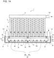
FIG. 14 is a schematic side view of a heat exchanger according to Embodiment 5, with a part thereof illustrated in sectional view. -
FIG. 15 is a schematic side view of a heat exchanger according to Embodiment 6, with a part thereof illustrated in sectional view. - Embodiments exemplifying the heat exchanger according to the present invention will now be described with reference to the drawings. In
Embodiment 1, an example of the air-conditioning apparatus according to the present invention will be described with reference to relevant drawings. In the drawings to be referred to below, like elements are denoted by like reference signs. Redundant description of the embodiments is omitted, if not necessary. The heat exchanger and the air-conditioning apparatus according to the present invention may include any combination of combinable features to be described in the following embodiments. -
FIG. 1 is a refrigerant circuit diagram illustrating an air-conditioning apparatus according toEmbodiment 1. - The air-conditioning apparatus, 100, according to
Embodiment 1 includes aheat exchanger 1 according toEmbodiment 1. In the air-conditioning apparatus 100 exemplified inFIG. 1 , theheat exchanger 1 is employed as an outdoor heat exchanger. Specifically, the air-conditioning apparatus 100 includes acompressor 101; anindoor heat exchanger 105, which serves as a condenser in a heating operation; anexpansion valve 104, which is configured to expand refrigerant discharged from the condenser; and theheat exchanger 1, which is employed as an outdoor heat exchanger that serves as an evaporator in the heating operation. - The
compressor 101, theindoor heat exchanger 105, theexpansion valve 104, and theheat exchanger 1 employed as an outdoor heat exchanger are connected to one another by refrigerant pipes, whereby a refrigerant circuit is formed for refrigerant to circulate therethrough. Hereinafter, one of the refrigerant pipes that connects between thecompressor 101 and theheat exchanger 1 is denoted as arefrigerant pipe 122, and another one of the refrigerant pipes that connects between theexpansion valve 104 and theheat exchanger 1 is denoted as arefrigerant pipe 121. - The refrigerant circuit of the air-
conditioning apparatus 100 according toEmbodiment 1 further includes anaccumulator 107, which is configured to accumulate excess refrigerant and is provided on the suction side of thecompressor 101. The air-conditioning apparatus 100 according toEmbodiment 1 is also capable of performing a cooling operation. - Therefore, the air-
conditioning apparatus 100 includes a four-way valve 102. The four-way valve 102 is configured to switch the heat exchangers to be connected to the discharge port of thecompressor 101 and to switch the heat exchangers to be connected to the suction port of thecompressor 101. In the cooling operation, theindoor heat exchanger 105 serves as an evaporator, whereas theheat exchanger 1 employed as an outdoor heat exchanger serves as a condenser. - The above elements forming the refrigerant circuit of the air-
conditioning apparatus 100 are each included in either anoutdoor unit 111 or anindoor unit 112. Specifically, thecompressor 101, the four-way valve 102, theheat exchanger 1 employed as an outdoor heat exchanger, and theaccumulator 107 are included in theoutdoor unit 111. Theindoor heat exchanger 105 and theexpansion valve 104 are included in theindoor unit 112. Theoutdoor unit 111 further includes afan 103, which is configured to supply outdoor air to theheat exchanger 1 employed as an outdoor heat exchanger. - The
indoor unit 112 further includes afan 106, which is configured to supply indoor air to theindoor heat exchanger 105. The air-conditioning apparatus 100 includes at least oneindoor unit 112. The air-conditioning apparatus 100 exemplified inFIG. 1 includes threeindoor units 112. If the air-conditioning apparatus 100 includes a plurality ofindoor units 112, theindoor units 112 are, for example, connected in parallel with each other to theoutdoor unit 111. - In the heating operation of the air-
conditioning apparatus 100, refrigerant circulates as represented by broken-line arrows inFIG. 1 . Specifically, to start the heating operation in the air-conditioning apparatus 100, the four-way valve 102 is switched to establish a passageway represented by broken lines inFIG. 1 . Accordingly, the discharge port of thecompressor 101 is connected to theindoor heat exchanger 105, and the suction port of thecompressor 101 is connected to theheat exchanger 1 employed as an outdoor heat exchanger. - That is, the
indoor heat exchanger 105 serves as a condenser, whereas theheat exchanger 1 employed as an outdoor heat exchanger serves as an evaporator. In this state, a gas refrigerant compressed by thecompressor 101 to have a high temperature and a high pressure is discharged from thecompressor 101 and flows into theindoor heat exchanger 105. The high-temperature high-pressure gas refrigerant flowing in theindoor heat exchanger 105 condenses while rejecting heat to the indoor air supplied from thefan 106, thereby turning into a high-pressure liquid refrigerant, which is discharged from theindoor heat exchanger 105. In this process, the indoor air is heated. - The high-pressure liquid refrigerant discharged from the
indoor heat exchanger 105 flows into theexpansion valve 104. The high-pressure liquid refrigerant flowing in theexpansion valve 104 is expanded by theexpansion valve 104, thereby turning into a low-temperature low-pressure two-phase gas-liquid refrigerant, which is discharged from theexpansion valve 104. The low-temperature low-pressure two-phase gas-liquid refrigerant discharged from theexpansion valve 104 flows through therefrigerant pipe 121 into theheat exchanger 1 employed as an outdoor heat exchanger. - The low-temperature low-pressure two-phase gas-liquid refrigerant flowing in the
heat exchanger 1 employed as an outdoor heat exchanger evaporates by receiving heat from the outdoor air supplied from thefan 103, thereby turning into a low-pressure gas refrigerant, which is discharged from theheat exchanger 1 employed as an outdoor heat exchanger. The low-pressure gas refrigerant discharged from theheat exchanger 1 employed as an outdoor heat exchanger flows through therefrigerant pipe 122 and is suctioned into thecompressor 101. The low-pressure gas refrigerant suctioned into thecompressor 101 is compressed by thecompressor 101, thereby turning into a high-temperature high-pressure gas refrigerant. The high-temperature high-pressure gas refrigerant is discharged from thecompressor 101 again. - In the cooling operation of the air-
conditioning apparatus 100, refrigerant circulates as represented by solid-line arrows inFIG. 1 . Specifically, to start the cooling operation in the air-conditioning apparatus 100, the four-way valve 102 is switched to establish a passageway represented by solid lines inFIG. 1 . Accordingly, the discharge port of thecompressor 101 is connected to theheat exchanger 1 employed as an outdoor heat exchanger, and the suction port of thecompressor 101 is connected to theindoor heat exchanger 105. That is, theheat exchanger 1 employed as an outdoor heat exchanger serves as a condenser, whereas theindoor heat exchanger 105 serves as an evaporator. - In this state, a gas refrigerant compressed by the
compressor 101 to have a high temperature and a high pressure is discharged from thecompressor 101 and flows through therefrigerant pipe 122 into theheat exchanger 1 employed as an outdoor heat exchanger. The high-temperature high-pressure gas refrigerant flowing in theheat exchanger 1 employed as an outdoor heat exchanger condenses while rejecting heat to the outdoor air supplied from thefan 103, thereby turning into a high-pressure liquid refrigerant, which is discharged from theheat exchanger 1 employed as an outdoor heat exchanger. - The high-pressure liquid refrigerant discharged from the
heat exchanger 1 employed as an outdoor heat exchanger flows through therefrigerant pipe 121 into theexpansion valve 104. The high-pressure liquid refrigerant flowing in theexpansion valve 104 is expanded by theexpansion valve 104, thereby turning into a low-temperature low-pressure two-phase gas-liquid refrigerant, which is discharged from theexpansion valve 104. The low-temperature low-pressure two-phase gas-liquid refrigerant discharged from theexpansion valve 104 flows into theindoor heat exchanger 105. - The low-temperature low-pressure two-phase gas-liquid refrigerant flowing in the
indoor heat exchanger 105 evaporates by receiving heat from the indoor air supplied from thefan 106, thereby turning into a low-pressure gas refrigerant, which is discharged from theindoor heat exchanger 105. In this process, the indoor air is cooled. The low-pressure gas refrigerant discharged from theindoor heat exchanger 105 is suctioned into thecompressor 101. The low-pressure gas refrigerant suctioned into thecompressor 101 is compressed by thecompressor 101, thereby turning into a high-temperature high-pressure gas refrigerant. The high-temperature high-pressure gas refrigerant is discharged from thecompressor 101 again. -
FIG. 2 is a schematic side view of the heat exchanger according toEmbodiment 1, with a part thereof illustrated in sectional view.FIG. 3 is a sectional view of a part, including a refrigerant distributer, of the heat exchanger according toEmbodiment 1, taken along line A-A given inFIG. 2 . Arrows with black solid heads illustrated inFIGS. 2 and thereafter represent the flow direction of the refrigerant in theheat exchanger 1 when theheat exchanger 1 is used as an evaporator. - The
heat exchanger 1 includes arefrigerant distributer 10, a plurality ofheat transfer tubes 2, a plurality offins 3, and a merging pipe 4. With theheat exchanger 1 installed in the air-conditioning apparatus 100, therefrigerant distributer 10 is laid out in, for example, the horizontal direction. The plurality ofheat transfer tubes 2 are arranged side by side at intervals. One end of each of theheat transfer tubes 2 is connected to therefrigerant distributer 10. - In
Embodiment 1, the lower ends of theheat transfer tubes 2 are connected to therefrigerant distributer 10. The plurality offins 3 are each provided between corresponding adjacent two of theheat transfer tubes 2 and are connected to theheat transfer tubes 2. The merging pipe 4 receives the other end of each of theheat transfer tubes 2. InEmbodiment 1, the upper ends of theheat transfer tubes 2 flows in the merging pipe 4. - When the
heat exchanger 1 is used as an evaporator, the refrigerant flowing from the outside toward theheat exchanger 1 first flows into therefrigerant distributer 10. The refrigerant flowing in therefrigerant distributer 10 is distributed in portions to theheat transfer tubes 2, and the refrigerant portions flow into the respectiveheat transfer tubes 2. The refrigerant portions flowing in theheat transfer tubes 2 exchange heat with air through theheat transfer tubes 2 and thefins 3. The refrigerant portions are then discharged from theheat transfer tubes 2 and are collected together by the merging pipe 4. The collected refrigerant is discharged from the merging pipe 4 to the outside of theheat exchanger 1. - When the
heat exchanger 1 is used as a condenser, the refrigerant flowing from the outside toward theheat exchanger 1 first flows into the merging pipe 4. The refrigerant flowing in the merging pipe 4 is distributed in portions to theheat transfer tubes 2, and the refrigerant portions flow into the respectiveheat transfer tubes 2. The refrigerant portions flowing in theheat transfer tubes 2 exchange heat with air through theheat transfer tubes 2 and thefins 3. - The refrigerant portions are then discharged from the
heat transfer tubes 2 and are collected together by therefrigerant distributer 10. The collected refrigerant is discharged from therefrigerant distributer 10 to the outside of theheat exchanger 1. Therefore, therefrigerant pipe 121 is connected to therefrigerant distributer 10, and therefrigerant pipe 122 is connected to the merging pipe 4. - When the
heat exchanger 1 is used as an evaporator, as described above, the refrigerant flowing from the outside into therefrigerant distributer 10 is distributed to theheat transfer tubes 2. That is, therefrigerant distributer 10 distributes a two-phase gas-liquid refrigerant to theheat transfer tubes 2. To distribute the two-phase gas-liquid refrigerant to theheat transfer tubes 2 while reducing the probability of deterioration in the heat-exchange performance of theheat exchanger 1, it is important to evenly distribute the liquid refrigerant component of the two-phase gas-liquid refrigerant to theheat transfer tubes 2. In this respect, theheat exchanger 1 according toEmbodiment 1 employs therefrigerant distributer 10 configured as illustrated inFIG. 2 . Specifically, therefrigerant distributer 10 has a double-pipe structure and includes anouter pipe 20, aninner pipe 30, and afirst partition 11. - The
outer pipe 20 is a pipe member with the both ends thereof closed. Theouter pipe 20 has a plurality ofconnection parts 21, which are arranged at intervals in the longitudinal direction of theouter pipe 20 and to each of which a corresponding one of theheat transfer tubes 2 is connected. That is, the plurality ofheat transfer tubes 2 are arranged side by side at intervals in the longitudinal direction of theouter pipe 20. - Herein, the longitudinal direction of the
outer pipe 20 refers to the direction in which theouter pipe 20 extends and is also regarded as the axial direction of theouter pipe 20. InFIG. 2 , the left-right direction in the plane of the page matches with the longitudinal direction of theouter pipe 20. Theouter pipe 20 may be bent at least in part thereof. The longitudinal direction of such anouter pipe 20 at any given point is regarded as the axial direction of theouter pipe 20 at that given point. - The
inner pipe 30 is a pipe member with at least one end thereof open. The one end is referred to as afirst end 31. In other words, theinner pipe 30 is a pipe member having anopening 31a at least at thefirst end 31 thereof. InEmbodiment 1, theinner pipe 30 is a pipe member with the both ends thereof open. That is, theinner pipe 30 according toEmbodiment 1 is open also at the other end, which is asecond end 32 and is located opposite thefirst end 31. - In other words, the
inner pipe 30 according toEmbodiment 1 has anopening 32a at thesecond end 32 thereof. Theinner pipe 30 is provided inside theouter pipe 20. With theinner pipe 30 placed inside theouter pipe 20, theopening 31a at thefirst end 31 communicates with the space inside theouter pipe 20. Furthermore, with theinner pipe 30 placed inside theouter pipe 20, theopening 32a at thesecond end 32 is closed by an end wall of theouter pipe 20. Theinner pipe 30 has at the periphery thereof a plurality offirst orifices 30a, which are also referred to as refrigerant discharge holes. The plurality offirst orifices 30a are arranged at intervals in the axial direction of theinner pipe 30. - In the above-configured
refrigerant distributer 10, the two-phase gas-liquid refrigerant flowing inside theinner pipe 30 is discharged through the plurality offirst orifices 30a to a space provided between the outer peripheral surface of theinner pipe 30 and the inner peripheral surface of theouter pipe 20, which will be described in detail separately below. The two-phase gas-liquid refrigerant discharged to the space between the outer peripheral surface of theinner pipe 30 and the inner peripheral surface of theouter pipe 20 flows through theconnection parts 21 of theouter pipe 20 into theheat transfer tubes 2. - In terms of distributing the two-phase gas-liquid refrigerant to the
heat transfer tubes 2, the plurality offirst orifices 30a may preferably be located as illustrated inFIG. 2 , although the locations of the plurality offirst orifices 30a are not limited. Specifically, thefirst orifices 30a may each preferably be located between corresponding adjacent two of theheat transfer tubes 2 in the axial direction of theinner pipe 30. - In the arrangement of the
first orifices 30a that is illustrated inFIG. 2 , the gas refrigerant component and the liquid refrigerant component of the two-phase gas-liquid refrigerant discharged into the space between the outer peripheral surface of theinner pipe 30 and the inner peripheral surface of theouter pipe 20 are mixed together in the space in a better way before flowing into theheat transfer tubes 2 than in an arrangement where thefirst orifices 30a are located vertically below the respectiveheat transfer tubes 2. That is, the arrangement of thefirst orifices 30a that is illustrated inFIG. 2 realizes more even distribution of the liquid refrigerant component of the two-phase gas-liquid refrigerant to theheat transfer tubes 2. - In the process of distributing the two-phase gas-liquid refrigerant to the
heat transfer tubes 2 as described above, if the axis of theinner pipe 30 is inclined significantly relative to the axis of theouter pipe 20 because of, for example, any bend in theinner pipe 30, the effect of evenly distributing the liquid refrigerant component of the two-phase gas-liquid refrigerant to theheat transfer tubes 2 is reduced. In such a case, since the liquid refrigerant component of the two-phase gas-liquid refrigerant tends to flow unevenly inside theinner pipe 30, the flow of the liquid refrigerant component of the two-phase gas-liquid refrigerant in the space between the outer peripheral surface of theinner pipe 30 and the inner peripheral surface of theouter pipe 20 tends to become uneven. - Hence, in the
refrigerant distributer 10 according toEmbodiment 1, theinner pipe 30 is held at positions close to the both ends thereof, whereby the axis of theinner pipe 30 is prevented from incline significantly relative to the axis of theouter pipe 20. Such a configuration realizes more even distribution of the liquid refrigerant component of the two-phase gas-liquid refrigerant to theheat transfer tubes 2. - Specifically, the
outer pipe 20 is provided thereinside with thefirst partition 11. Thefirst partition 11 has a first through-hole 11a. A portion of theinner pipe 30 that is close to thefirst end 31 is fitted in the first through-hole 11a of thefirst partition 11. Thus, the portion of theinner pipe 30 that is close to thefirst end 31 is held by thefirst partition 11. Thesecond end 32 of theinner pipe 30 is held by theouter pipe 20 by, for example, being fixed to the end wall of theouter pipe 20. - As illustrated in
FIG. 3 , thefirst partition 11 closes the space provided between the outer peripheral surface of theinner pipe 30 and the inner peripheral surface of theouter pipe 20. Hence, as illustrated inFIG. 2 , the inside of theouter pipe 20 is separated by thefirst partition 11 into amain space 40 and afirst space 41. Themain space 40 is a space with which the plurality offirst orifices 30a and the plurality ofconnection parts 21 communicate. Thefirst space 41 communicates with none of the plurality offirst orifices 30a and the plurality ofconnection parts 21. Thefirst space 41 is a space with which theopening 31a provided at thefirst end 31 of theinner pipe 30 communicates. - In the
refrigerant distributer 10 according toEmbodiment 1, the refrigerant flowing from the outside toward therefrigerant distributer 10 is temporarily supplied into thefirst space 41. Specifically, in therefrigerant distributer 10 according toEmbodiment 1, the refrigerant supplied from the outside into thefirst space 41 flows into the plurality ofheat transfer tubes 2 after flowing through the inside of theinner pipe 30, the plurality offirst orifices 30a, themain space 40, and the plurality ofconnection parts 21. - The
outer pipe 20 according toEmbodiment 1 has aconnection part 22, which communicates with thefirst space 41. Therefrigerant pipe 121 is connected to theconnection part 22. Therefore, when theheat exchanger 1 is used as an evaporator, the two-phase gas-liquid refrigerant is supplied into thefirst space 41 of therefrigerant distributer 10 through therefrigerant pipe 121. In such a configuration where therefrigerant pipe 121 is connected to theouter pipe 20, the way of connection of therefrigerant pipe 121 to theouter pipe 20 may preferably be as illustrated inFIG. 2 . - Specifically, the
refrigerant pipe 121 connected to theouter pipe 20 may preferably extend in the direction in which theheat transfer tubes 2 extend. Such a way of connection of therefrigerant pipe 121 to theouter pipe 20 reduces the length of the space occupied by therefrigerant pipe 121 in the direction in which the plurality ofheat transfer tubes 2 are arranged side by side. - Hence, the above way of connection of the
refrigerant pipe 121 to theouter pipe 20 allows an increased number ofheat transfer tubes 2 to be arranged side by side in the space of the air-conditioning apparatus 100 that is provided for the installation of theheat exchanger 1 and therefrigerant pipe 121. Accordingly, the above way of connection of therefrigerant pipe 121 to theouter pipe 20 increases the installability of theheat transfer tubes 2 in theheat exchanger 1. - Some known heat exchangers include double-pipe refrigerant distributers, aiming to realize even distribution of the liquid refrigerant component of the two-phase gas-liquid refrigerant to the heat transfer tubes. Such a known double-pipe refrigerant distributer does not have the
first space 41 inside the outer pipe thereof, allowing the refrigerant on the outside to flow directly into the inner pipe. Therefore, the heat exchanger including the known double-pipe refrigerant distributer may experience a deterioration of the heat-exchange performance thereof when the liquid refrigerant component of the two-phase gas-liquid refrigerant is unevenly distributed to the heat transfer tubes, depending on the condition of the two-phase gas-liquid refrigerant flowing inside the inner pipe. Such condition may occur where the distribution of the liquid refrigerant component of the two-phase gas-liquid refrigerant flows unevenly inside the inner pipe. - In contrast, in the
heat exchanger 1 according toEmbodiment 1, the gas refrigerant component and the liquid refrigerant component of the two-phase gas-liquid refrigerant flowing from the outside flows in thefirst space 41 of therefrigerant distributer 10 and are mixed together in thefirst space 41. The two-phase gas-liquid refrigerant with the gas refrigerant component and the liquid refrigerant component thereof thus mixed together is distributed to the plurality ofheat transfer tubes 2 after flowing through the inside of theinner pipe 30, thefirst orifices 30a, themain space 40, and theconnection parts 21 of theouter pipe 20. - Therefore, in the
heat exchanger 1 according toEmbodiment 1, the liquid refrigerant component of the two-phase gas-liquid refrigerant is prevented from flowing unevenly inside theinner pipe 30, realizing a stable flow of the two-phase gas-liquid refrigerant in theinner pipe 30. Hence, in theheat exchanger 1 according toEmbodiment 1, the liquid refrigerant component of the two-phase gas-liquid refrigerant is distributed more evenly to theheat transfer tubes 2 than in the known art. - To summarize, the
heat exchanger 1 according toEmbodiment 1 includes the plurality ofheat transfer tubes 2, theouter pipe 20, theinner pipe 30, and thefirst partition 11. Theouter pipe 20 has the plurality ofconnection parts 21 that are arranged at intervals in the longitudinal direction and to each of which a corresponding one of the plurality ofheat transfer tubes 2 is connected. Theinner pipe 30 has the plurality offirst orifices 30a at the periphery. Theinner pipe 30 is provided inside theouter pipe 20. Thefirst partition 11 has the first through-hole 11a in which theinner pipe 30 is fitted. Thefirst partition 11 separates the inside of theouter pipe 20 into themain space 40 and thefirst space 41. - The
main space 40 is a space with which the plurality offirst orifices 30a and the plurality ofconnection parts 21 communicate. Thefirst space 41 communicates with none of the plurality offirst orifices 30a and the plurality ofconnection parts 21. Thefirst space 41 is a space with which theopening 31a provided at thefirst end 31 of theinner pipe 30 communicates. In therefrigerant distributer 10 according toEmbodiment 1, the refrigerant supplied into thefirst space 41 flows into the plurality ofheat transfer tubes 2 after flowing through the inside of theinner pipe 30, the plurality offirst orifices 30a, themain space 40, and the plurality ofconnection parts 21. - In the
heat exchanger 1 configured as above, the liquid refrigerant component of the two-phase gas-liquid refrigerant is prevented from flowing unevenly inside theinner pipe 30, realizing a stable flow of the two-phase gas-liquid refrigerant in theinner pipe 30. Hence, in theheat exchanger 1 according toEmbodiment 1, the liquid refrigerant component of the two-phase gas-liquid refrigerant is distributed more evenly to theheat transfer tubes 2 than in the known art. - While the
heat exchanger 1 according toEmbodiment 1 is employed as an outdoor heat exchanger of the air-conditioning apparatus 100, theheat exchanger 1 is not limited thereto. Theheat exchanger 1 may alternatively be employed as theindoor heat exchanger 105 of the air-conditioning apparatus 100. Moreover, for example, theheat exchanger 1 may be applied to both the outdoor heat exchanger and theindoor heat exchanger 105 of the air-conditioning apparatus 100. - As to be described in
Embodiment 2, if asecond space 42 is further provided inside theouter pipe 20 of therefrigerant distributer 10, the liquid refrigerant component of the two-phase gas-liquid refrigerant is distributed further more evenly to theheat transfer tubes 2. Features that are not described inEmbodiment 2 are the same as those described inEmbodiment 1. -
FIG. 4 is a schematic side view of a heat exchanger according toEmbodiment 2, with a part thereof illustrated in sectional view. - In addition to the elements employed in
Embodiment 1, theheat exchanger 1 according toEmbodiment 2 includes asecond partition 12, which is provided in therefrigerant distributer 10. Thesecond partition 12 is provided inside theouter pipe 20. Thesecond partition 12 has a second through-hole 12a. A portion of theinner pipe 30 that is close to thesecond end 32 is fitted in the second through-hole 12a of thesecond partition 12. Thus, the portion of theinner pipe 30 that is close to thesecond end 32 is held by thesecond partition 12. - The
second partition 12 closes the space provided between the outer peripheral surface of theinner pipe 30 and the inner peripheral surface of theouter pipe 20. Hence, the inside of theouter pipe 20 is separated by thesecond partition 12 into themain space 40 and thesecond space 42. As described above inEmbodiment 1, themain space 40 is a space with which the plurality offirst orifices 30a and the plurality ofconnection parts 21 communicate. Thesecond space 42 communicates with none of the plurality offirst orifices 30a and the plurality ofconnection parts 21. Thesecond space 42 is a space with which theopening 32a provided at thesecond end 32 of theinner pipe 30 communicates. - The
second space 42 has a larger area than the space inside theinner pipe 30 in a section taken perpendicularly to the axis of theinner pipe 30. In therefrigerant distributer 10 having thesecond space 42, the two-phase gas-liquid refrigerant flowing inside theinner pipe 30 flows into thesecond space 42 through theopening 32a provided at thesecond end 32 and strikes the end wall of theouter pipe 20. Thus, the liquid refrigerant component of the two-phase gas-liquid refrigerant is gathered in thesecond space 42. - Since the
second space 42 is provided inside theouter pipe 20 of therefrigerant distributer 10, the liquid refrigerant component of the two-phase gas-liquid refrigerant is prevented from being distributed by a greater amount to those of the plurality offirst orifices 30a that are located closer to thesecond end 32. That is, providing thesecond space 42 inside theouter pipe 20 of therefrigerant distributer 10 realizes further more even distribution of the liquid refrigerant component of the two-phase gas-liquid refrigerant to theheat transfer tubes 2. - The present inventors have elucidated the above mechanism of how the
second space 42 provided inside theouter pipe 20 improves the refrigerant distribution, through an experiment of visualizing the flow behavior of the two-phase gas-liquid refrigerant in therefrigerant distributer 10. Now, the mechanism of improvement in the refrigerant distribution that has been demonstrated by the present inventors will be described with reference toFIGS. 5 and6 . -
FIG. 5 is a sectional view of a refrigerant distributer according to Comparative Example.FIG. 6 is a sectional view of the refrigerant distributer according toEmbodiment 2. In the following description of arefrigerant distributer 210 according to Comparative Example, elements that are the same as those of therefrigerant distributer 10 according toEmbodiment 2 are denoted by same reference signs as used for therefrigerant distributer 10 according toEmbodiment 2. - The
refrigerant distributer 210 according to Comparative Example has nosecond space 42 inside theouter pipe 20. Therefore, in therefrigerant distributer 210 according to Comparative Example, theopening 32a provided at thesecond end 32 of theinner pipe 30 is closed by the end wall of theouter pipe 20. The other details of therefrigerant distributer 210 according to Comparative Example are the same as those of therefrigerant distributer 10 according toEmbodiment 2. - If, for example, the two-phase gas-liquid refrigerant in the
inner pipe 30 flows at a high speed and a large inertial force acts on the two-phase gas-liquid refrigerant flowing in theinner pipe 30, an excessive amount of liquid refrigerant component of the two-phase gas-liquid refrigerant may reach thesecond end 32 of theinner pipe 30. In therefrigerant distributer 210 according to Comparative Example that has nosecond space 42, if an excessive amount of liquid refrigerant component of the two-phase gas-liquid refrigerant flows toward thesecond end 32 of theinner pipe 30, the liquid refrigerant component of the two-phase gas-liquid refrigerant flowing toward thesecond end 32 of theinner pipe 30 first strikes the end wall of theouter pipe 20 and is then discharged to themain space 40 through thosefirst orifices 30a that are located close to thesecond end 32. - Therefore, in the
refrigerant distributer 210 according to Comparative Example, if an excessive amount of liquid refrigerant component of the two-phase gas-liquid refrigerant reaches thesecond end 32 of theinner pipe 30, a greater amount of liquid refrigerant component of the two-phase gas-liquid refrigerant is distributed to those of the plurality offirst orifices 30a that are located closer to thesecond end 32. - In contrast, in the
refrigerant distributer 10 according toEmbodiment 2 that has thesecond space 42, the liquid refrigerant component of the two-phase gas-liquid refrigerant flowing toward thesecond end 32 of theinner pipe 30 first flows into thesecond space 42 through theopening 32a provided at thesecond end 32 and then strikes the end wall of theouter pipe 20. The liquid refrigerant component of the two-phase gas-liquid refrigerant thus reached thesecond space 42 is gathered in thesecond space 42. - That is, the
second space 42 serves as a stagnation space where the liquid refrigerant component of the two-phase gas-liquid refrigerant is to be gathered. The stagnation space may also be referred to as buffer tank. The two-phase gas-liquid refrigerant flowing in theinner pipe 30 is pulsating. - Therefore, with the elapse of a certain time, some of the liquid refrigerant component gathered in the
second space 42 flows backward, toward upstream ones of thefirst orifices 30a of theinner pipe 30. Therefore, on the basis of time average, providing thesecond space 42 inside theouter pipe 20 of therefrigerant distributer 10 realizes further more even distribution of the liquid refrigerant component of the two-phase gas-liquid refrigerant to theheat transfer tubes 2. - If the
first space 41 and thesecond space 42 are provided inside theouter pipe 20 as inEmbodiment 2, thefirst space 41 and thesecond space 42 may preferably be sized as follows. Referring toFIG. 4 , the length of thefirst space 41 in the longitudinal direction of theouter pipe 20 is defined as a length L1, and the length of thesecond space 42 in the longitudinal direction of theouter pipe 20 is defined as a length L2. Under such definitions of the length L1 and the length L2, the length L1 may preferably be greater than the length L2. What is important here is that thesecond space 42 is provided inside theouter pipe 20. Even if the length L2 is small, the above advantageous effects are produced. - Furthermore, making the length L2 small allows an increased number of
heat transfer tubes 2 to be arranged side by side in the space of the air-conditioning apparatus 100 that is provided for the installation of theheat exchanger 1. That is, making the length L2 small increases the installability of theheat transfer tubes 2 in theheat exchanger 1. Therefore, the length L1 may preferably be greater than the length L2. - If the
first space 41 and thesecond space 42 are provided inside theouter pipe 20 as inEmbodiment 2, the state of fitting of thefirst end 31 of theinner pipe 30 in thefirst partition 11 and the state of fitting of thesecond end 32 of theinner pipe 30 in thesecond partition 12 may be determined as follows, in correspondence with the advantageous effects desired. - For example, if the ease of assembly of the
refrigerant distributer 10 is desired, as illustrated inFIG. 4 , thefirst end 31 of theinner pipe 30 may preferably project into thefirst space 41, and thesecond end 32 of theinner pipe 30 may preferably project into thesecond space 42. Such a configuration prevents theinner pipe 30 from coming off thefirst partition 11 and thesecond partition 12 during the process of assembling therefrigerant distributer 10, and also prevents the axis of theinner pipe 30 from inclining significantly relative to the axis of theouter pipe 20 at the completion of assembling therefrigerant distributer 10. - In such a configuration, the length of projection of the
first end 31 of theinner pipe 30 into thefirst space 41 and the length of projection of thesecond end 32 of theinner pipe 30 into thesecond space 42 may preferably be defined as follows, for example. Referring toFIG. 4 , the length by which theinner pipe 30 projects into thefirst space 41 is defined as a projection length t1, and the length by which theinner pipe 30 projects into thesecond space 42 is defined as a projection length t2. - Under such definitions of the projection length t1 and the projection length t2, the projection length t1 may preferably be smaller than the projection length t2. Setting the projection length t1 smaller than the projection length t2 increases the size of the
first space 41. Thefirst space 41 is preferred to have a large capacity so that the liquid refrigerant component of the two-phase gas-liquid refrigerant can be distributed evenly to theheat transfer tubes 2. - If the projection length t1 is set smaller than the projection length t2, it is preferable that, in the process of assembling the
refrigerant distributer 10, theinner pipe 30 be inserted into theouter pipe 20 from the end of theouter pipe 20 where thefirst space 41 is provided. Such a process facilitates the insertion of theinner pipe 30 into the second partition, which is one of thefirst partition 11 and thesecond partition 12 that is located on the far side in the assembling process. Hence, the assembly of therefrigerant distributer 10 is further facilitated. - If the liquid refrigerant component of the two-phase gas-liquid refrigerant is desired distributed further more evenly to the
heat transfer tubes 2, the state of fitting of thefirst end 31 of theinner pipe 30 in thefirst partition 11 and the state of fitting of thesecond end 32 of theinner pipe 30 in thesecond partition 12 may be determined as illustrated inFIG. 7 . -
FIG. 7 is a sectional view of another exemplary refrigerant distributer according toEmbodiment 2. - In the
refrigerant distributer 10 illustrated inFIG. 7 , thefirst end 31 of theinner pipe 30 is located in the first through-hole 11a of thefirst partition 11. In other words, thefirst end 31 of theinner pipe 30 does not project into thefirst space 41. Likewise, in therefrigerant distributer 10 illustrated inFIG. 7 , thesecond end 32 of theinner pipe 30 is located in the second through-hole 12a of thesecond partition 12. In other words, thesecond end 32 of theinner pipe 30 does not project into thesecond space 42. - In such a
refrigerant distributer 10, thefirst space 41 and thesecond space 42 are larger than in the case where theinner pipe 30 projects into thefirst space 41 and thesecond space 42. Accordingly, such arefrigerant distributer 10 realizes further more even distribution of the liquid refrigerant component of the two-phase gas-liquid refrigerant to theheat transfer tubes 2. - The way of holding the
inner pipe 30 by thefirst partition 11 as illustrated inFIG. 7 may also be applied to theheat exchanger 1 according toEmbodiment 1. In that case, thefirst space 41 becomes larger and the distribution of the liquid refrigerant component of the two-phase gas-liquid refrigerant to theheat transfer tubes 2 becomes further more even than in the case where theinner pipe 30 projects into thefirst space 41. - If the
heat exchanger 1 includes thesecond partition 12, thesecond partition 12 may have asecond orifice 12b as inEmbodiment 3. Features that are not described inEmbodiment 3 are the same as those described inEmbodiment -
FIG. 8 is a schematic side view of a heat exchanger according toEmbodiment 3, with a part thereof illustrated in sectional view.FIG. 9 is a sectional view of a refrigerant distributer of the heat exchanger according toEmbodiment 3, illustrating a part around a second space. - As with the case of the
heat exchanger 1 according toEmbodiment 2, theheat exchanger 1 according toEmbodiment 3 includes thesecond partition 12, and thesecond space 42 provided inside theouter pipe 20. Thesecond partition 12 of theheat exchanger 1 according toEmbodiment 3 has at least onesecond orifice 12b, which allows themain space 40 and thesecond space 42 to communicate with each other. - As described in
Embodiment 2, since thesecond space 42 is provided inside theouter pipe 20, an excessive amount of liquid refrigerant component of the two-phase gas-liquid refrigerant reaching thesecond end 32 of theinner pipe 30 is gathered in thesecond space 42. Such a configuration realizes even distribution of the liquid refrigerant component of the two-phase gas-liquid refrigerant to theheat transfer tubes 2. In theheat exchanger 1 according toEmbodiment 2, the pulsation of the two-phase gas-liquid refrigerant flowing in theinner pipe 30 causes some of the liquid refrigerant component gathered in thesecond space 42 to flow backward into theinner pipe 30. - In the
heat exchanger 1 according toEmbodiment 3, some of the liquid refrigerant component gathered in thesecond space 42 is allowed to flow through thesecond orifice 12b into themain space 40. That is, in the configuration where thesecond space 42 is provided to realize even distribution of the liquid refrigerant component of the two-phase gas-liquid refrigerant to theheat transfer tubes 2, thesecond orifice 12b provided in thesecond partition 12 further allows an increased amount of liquid refrigerant component distributed to theheat transfer tubes 2. Consequently, thesecond orifice 12b provided in thesecond partition 12 further mitigates deterioration in the heat-exchange performance of theheat exchanger 1. - As described above, the
second partition 12 may have at least onesecond orifice 12b. That is, thesecond partition 12 may have a singlesecond orifice 12b or a plurality ofsecond orifices 12b. Anysecond orifices 12b to be provided in thesecond partition 12 may preferably be located as follows. Now, a preferable location of thesecond orifices 12b will be described with reference toFIGS. 10 and 11 . -
FIGS. 10 and 11 are each a sectional view of a part, including an exemplary refrigerant distributer, of the heat exchanger according toEmbodiment 3. Specifically,FIGS. 10 and 11 each illustrate a section of the part, including the exemplary refrigerant distributer, of the heat exchanger according toEmbodiment 3 that is taken perpendicularly to the longitudinal direction of theouter pipe 20. More specifically,FIGS. 10 and 11 each illustrate a section of the part, including the exemplary refrigerant distributer, of the heat exchanger according toEmbodiment 3 that is taken along line B-B given inFIG. 8 . - As illustrated in
FIG. 10 or 11 , in the section perpendicular to the longitudinal direction of theouter pipe 20, eachsecond orifice 12b may preferably be at such a location as not to interfere with thefirst orifices 30a provided in theinner pipe 30. The location that does not interfere with thefirst orifices 30a in the section perpendicular to the longitudinal direction of theouter pipe 20 referred to any location that is off the extension of the axis, 30b, of each of thefirst orifices 30a. - Providing the
second orifice 12b at such a location mitigates interference between the flow of the refrigerant from thesecond orifice 12b into themain space 40 and the flow of the refrigerant from thefirst orifices 30a into themain space 40. Consequently, the flow of the refrigerant in themain space 40 is stabilized, realizing more even distribution of the liquid refrigerant component of the two-phase gas-liquid refrigerant to theheat transfer tubes 2. - As the size of the
second orifice 12b is increased, an increased portion of the liquid refrigerant component gathered in thesecond space 42 is allowed to flow into themain space 40 through thesecond orifice 12b. In this respect, thesecond orifice 12b may preferably be sized as follows, for example. The opening area of one of the plurality offirst orifices 30a is defined as an opening area S1, and the sum total of the opening areas of all of thesecond orifices 12b is defined as an opening area S2. Under such definitions of the opening area S1 and the opening area S2, the opening area S2 may preferably be larger than the opening area S1. That is, the sum total of the refrigerant flow rates at all of thesecond orifices 12b may preferably be greater than the refrigerant flow rate at each of thefirst orifices 30a. - The
heat exchanger 1 may include anintermediate partition 13 as in Embodiment 4. Features that are not described in Embodiment 4 are the same as those described in any ofEmbodiments 1 to 3. -
FIG. 12 is a schematic side view of a heat exchanger according to Embodiment 4, with a part thereof illustrated in sectional view. - The
heat exchanger 1 according to Embodiment 4 includes at least oneintermediate partition 13. Theintermediate partition 13 is provided inside theouter pipe 20 and between thefirst partition 11 and thesecond partition 12. Theintermediate partition 13 has an intermediate-partition through-hole 13a. A middle portion of theinner pipe 30 is fitted in the intermediate-partition through-hole 13a of theintermediate partition 13. That is, theintermediate partition 13 holds the middle portion of theinner pipe 30 and separates themain space 40 into a plurality of spaces. Such spaces are hereinafter referred to as main-space areas 40a. - Since the
intermediate partition 13 is provided, the axis of theinner pipe 30, which may be long, is prevented from inclining significantly relative to the axis of theouter pipe 20 because of a bend in theinner pipe 30 or any other factor. Therefore, even if theinner pipe 30 is long, the liquid refrigerant component of the two-phase gas-liquid refrigerant is distributed evenly to theheat transfer tubes 2 with the aid of theintermediate partition 13. -
FIG. 13 is a schematic side view of another exemplary heat exchanger according to Embodiment 4, with a part thereof illustrated in sectional view. - In the
heat exchanger 1 according to Embodiment 4, as illustrated inFIG. 13 , theintermediate partition 13 may have at least one intermediate-partition orifice 13b, or may have no intermediate-partition orifice 13b as illustrated inFIG. 12 . The intermediate-partition orifice 13b is a through-hole that allows adjacent ones of the main-space areas 40a to communicate with each other. - The effects to be produced vary with whether the
intermediate partition 13 has any intermediate-partition orifices 13b. For example, if theintermediate partition 13 has no intermediate-partition orifice 13b as illustrated inFIG. 12 , an increased effect is produced in terms of fluid-resistance adjustment by the plurality offirst orifices 30a provided in theinner pipe 30. Consequently, the liquid refrigerant component of the two-phase gas-liquid refrigerant is distributed more evenly to theheat transfer tubes 2. - In another respect, as described for the air-
conditioning apparatus 100 according toEmbodiment 1, if theheat exchanger 1 is used as a condenser as well, therefrigerant distributer 10 serves as a merging pipe where refrigerant portions discharged from theheat transfer tubes 2 into therefrigerant distributer 10 are collected. In such a case, if theintermediate partition 13 has at least one intermediate-partition orifice 13b as illustrated inFIG. 13 , the fluid resistance in therefrigerant distributer 10 is reduced. - Any
heat exchanger 1 that includes thesecond partition 12 may be configured as in Embodiment 5. Features that are not described in Embodiment 5 are the same as those described in any ofEmbodiments 1 to 4. -
FIG. 14 is a schematic side view of a heat exchanger according to Embodiment 5, with a part thereof illustrated in sectional view. - The
heat exchanger 1 according to Embodiment 5 is configured such that not only thefirst space 41 but also thesecond space 42 is supplied with the two-phase gas-liquid refrigerant. Therefore, in theheat exchanger 1 according to Embodiment 5, a refrigerant portion supplied into thefirst space 41 and a refrigerant portion supplied into thesecond space 42 flow into the plurality ofheat transfer tubes 2 after flowing through the inside of theinner pipe 30, the plurality offirst orifices 30a, themain space 40, and the plurality ofconnection parts 21. - In Embodiment 5, the
outer pipe 20 has aconnection part 23, which communicates with thesecond space 42. Therefrigerant pipe 121 is connected to theconnection part 23. Therefore, when theheat exchanger 1 is used as an evaporator, a two-phase gas-liquid refrigerant is supplied through therefrigerant pipe 121 into thesecond space 42 of therefrigerant distributer 10. - In the
refrigerant distributer 10 configured to receive the two-phase gas-liquid refrigerant through the both ends thereof as in Embodiment 5, the following advantageous effects are produced, compared with therefrigerant distributer 10 configured to receive the two-phase gas-liquid refrigerant through one end thereof. The unevenness in the flow of the liquid refrigerant component of the two-phase gas-liquid refrigerant that is caused by any inclination of the axis of theinner pipe 30 relative to the axis of theouter pipe 20 is reduced. - Consequently, the probability of deterioration in the heat-exchange performance of the
heat exchanger 1 is reduced. The liquid refrigerant component of the two-phase gas-liquid refrigerant flowing with an inertial force is prevented from being distributed by a greater amount to thosefirst orifices 30a that are located closer to the downstream end of theinner pipe 30 in the direction of the flow of the two-phase gas-liquid refrigerant. - Consequently, the probability of deterioration in the heat-exchange performance of the
heat exchanger 1 is reduced. As described above, if theheat exchanger 1 is used as a condenser, therefrigerant distributer 10 serves as a merging pipe where refrigerant portions discharged from theheat transfer tubes 2 into therefrigerant distributer 10 are collected. In such a case, the fluid resistance in therefrigerant distributer 10 is significantly reduced. - The
refrigerant distributer 10 according to Embodiment 5 has thesecond space 42. If therefrigerant distributer 10 is configured to receive the two-phase gas-liquid refrigerant through the both ends thereof, the configuration according to Embodiment 5 facilitates the connection of therefrigerant pipe 121 to each of the both ends of therefrigerant distributer 10. - The
heat exchanger 1 may be a finless heat exchanger as in Embodiment 6. Features that are not described in Embodiment 6 are the same as those described in any ofEmbodiments 1 to 5. -
FIG. 15 is a schematic side view of a heat exchanger according to Embodiment 6, with a part thereof illustrated in sectional view. - The
heat exchanger 1 according to Embodiment 6 is a finless heat exchanger that includes nofins 3. Specifically, theheat exchanger 1 according to Embodiment 6 is obtained by removing thefins 3 from theheat exchanger 1 according to any ofEmbodiments 1 to 5.FIG. 15 illustrates an example obtained by removing thefins 3 from theheat exchanger 1 according to Embodiment 5. - What is important in a finless heat exchanger is the ease of dense installation of heat transfer tubes to increase the area of heat transfer. Therefore, the finless heat exchanger has a greater number of heat transfer tubes than the finned heat exchanger. In this respect, the
refrigerant distributer 10 according to any ofEmbodiments 1 to 5 that realizes more even distribution of the liquid refrigerant component of the two-phase gas-liquid refrigerant to theheat transfer tubes 2 than in the known refrigerant distributer is preferable as the refrigerant distributer of the finless heat exchanger. -
- 1:
- heat exchanger
- 2:
- heat transfer tube
- 3:
- fin
- 4:
- merging pipe
- 10:
- refrigerant distributer
- 11:
- first partition
- 11a:
- first through-hole
- 12:
- second partition
- 12a:
- second through-hole
- 12b:
- second orifice
- 13:
- intermediate partition
- 13a:
- intermediate-partition through-hole
- 13b:
- intermediate-partition orifice
- 20:
- outer pipe
- 21:
- connection part
- 22:
- connection part
- 23:
- connection part
- 30:
- inner pipe
- 30a:
- first orifice
- 30b:
- axis
- 31:
- first end
- 31a:
- opening
- 32:
- second end
- 32a:
- opening
- 40:
- main space
- 40a:
- main-space area
- 41:
- first space
- 42:
- second space
- 100:
- air-conditioning apparatus
- 101:
- compressor
- 102:
- four-way valve
- 103:
- fan
- 104:
- expansion valve
- 105:
- indoor heat exchanger
- 106:
- fan
- 107:
- accumulator
- 111:
- outdoor unit
- 112:
- indoor unit
- 121:
- refrigerant pipe
- 122:
- refrigerant pipe
- 210:
- refrigerant distributer (Comparative Example)
Claims (13)
- A heat exchanger comprising:a plurality of heat transfer tubes;an outer pipe having a plurality of connection parts that are arranged at intervals in a longitudinal direction and to each of which a corresponding one of the plurality of heat transfer tubes is connected;an inner pipe provided inside the outer pipe and having a plurality of first orifices at a periphery; anda first partition having a first through-hole in which the inner pipe is fitted, the first partition separating an inside of the outer pipe into a main space and a first space,wherein the main space is a space with which the plurality of first orifices and the plurality of connection parts communicate,wherein the first space communicates with none of the plurality of first orifices and the plurality of connection parts and is a space with which an opening provided at one end of the inner pipe communicates, the one end being a first end, andwherein refrigerant supplied into the first space flows into an inside of the inner pipe, the plurality of first orifices, the main space, the plurality of connection parts, and then the plurality of heat transfer tubes.
- The heat exchanger of claim 1,
further comprising:a second partition having a second through-hole in which the inner pipe is fitted, the second partition separating the inside of the outer pipe into the main space and a second space,wherein the second space communicates with none of the plurality of first orifices and the plurality of connection parts and is a space with which an opening provided at an other end of the inner pipe communicates, the other end being a second end located opposite the first end. - The heat exchanger of claim 2,
wherein, letting a length of the first space in the longitudinal direction be a length L1 and a length of the second space in the longitudinal direction be a length L2,
the length L1 is greater than the length L2. - The heat exchanger of claim 2 or 3,
further comprising:
an intermediate partition provided between the first partition and the second partition and separating the main space into a plurality of main-space areas. - The heat exchanger of claim 4,
wherein the intermediate partition has at least one intermediate-partition orifice that allows adjacent ones of the main-space areas to communicate with each other. - The heat exchanger of any one of claims 2 to 5,
wherein the second partition has at least one second orifice that allows the main space and the second space to communicate with each other. - The heat exchanger of claim 6,
wherein, lettingan opening area of one of the plurality of first orifices be an opening area S1 anda sum total of opening areas of all of the second orifices be an opening area S2,the opening area S2 is greater than the opening area S1. - The heat exchanger of any one of claims 2 to 5,
wherein a refrigerant portion supplied into the first space and a refrigerant portion supplied into the second space flow into an inside of the inner pipe, the plurality of first orifices, the main space, the plurality of connection parts, and then the plurality of heat transfer tubes. - The heat exchanger of any one of claims 2 to 8,wherein the first end of the inner pipe projects into the first space, andwherein the second end of the inner pipe projects into the second space.
- The heat exchanger of claim 9,
wherein, lettinga length by which the inner pipe projects into the first space be a projection length t1 anda length by which the inner pipe projects into the second space be a projection length t2,the projection length t1 is smaller than the projection length t2. - The heat exchanger of any one of claims 2 to 10,
wherein the second end of the inner pipe is located in the second through-hole of the second partition. - The heat exchanger of any one of claims 1 to 11,
wherein the first end of the inner pipe is located in the first through-hole of the first partition. - An air-conditioning apparatus comprising:
a heat exchanger of any one of claims 1 to 12.
Applications Claiming Priority (1)
| Application Number | Priority Date | Filing Date | Title |
|---|---|---|---|
| PCT/JP2022/018298 WO2023203683A1 (en) | 2022-04-20 | 2022-04-20 | Heat exchanger and air conditioning device |
Publications (2)
| Publication Number | Publication Date |
|---|---|
| EP4513122A1 true EP4513122A1 (en) | 2025-02-26 |
| EP4513122A4 EP4513122A4 (en) | 2025-06-04 |
Family
ID=88419460
Family Applications (1)
| Application Number | Title | Priority Date | Filing Date |
|---|---|---|---|
| EP22938485.4A Pending EP4513122A4 (en) | 2022-04-20 | 2022-04-20 | HEAT EXCHANGER AND AIR CONDITIONING DEVICE |
Country Status (5)
| Country | Link |
|---|---|
| US (1) | US20250244090A1 (en) |
| EP (1) | EP4513122A4 (en) |
| JP (1) | JP7370501B1 (en) |
| CN (1) | CN119013527A (en) |
| WO (1) | WO2023203683A1 (en) |
Family Cites Families (5)
| Publication number | Priority date | Publication date | Assignee | Title |
|---|---|---|---|---|
| KR101372096B1 (en) * | 2011-11-18 | 2014-03-07 | 엘지전자 주식회사 | A heat exchanger |
| JP5376010B2 (en) * | 2011-11-22 | 2013-12-25 | ダイキン工業株式会社 | Heat exchanger |
| JP6015229B2 (en) * | 2012-08-10 | 2016-10-26 | ダイキン工業株式会社 | Heat exchanger |
| US10072900B2 (en) * | 2014-09-16 | 2018-09-11 | Mahle International Gmbh | Heat exchanger distributor with intersecting streams |
| JP2018162901A (en) * | 2017-03-24 | 2018-10-18 | 日立ジョンソンコントロールズ空調株式会社 | Heat exchanger and air conditioner using the same |
-
2022
- 2022-04-20 EP EP22938485.4A patent/EP4513122A4/en active Pending
- 2022-04-20 CN CN202280094891.4A patent/CN119013527A/en active Pending
- 2022-04-20 WO PCT/JP2022/018298 patent/WO2023203683A1/en not_active Ceased
- 2022-04-20 US US18/855,039 patent/US20250244090A1/en active Pending
- 2022-04-20 JP JP2023535013A patent/JP7370501B1/en active Active
Also Published As
| Publication number | Publication date |
|---|---|
| JPWO2023203683A1 (en) | 2023-10-26 |
| CN119013527A (en) | 2024-11-22 |
| US20250244090A1 (en) | 2025-07-31 |
| EP4513122A4 (en) | 2025-06-04 |
| WO2023203683A1 (en) | 2023-10-26 |
| JP7370501B1 (en) | 2023-10-27 |
Similar Documents
| Publication | Publication Date | Title |
|---|---|---|
| CN112204312B (en) | Outdoor unit of air conditioner and air conditioner | |
| EP3370000B1 (en) | Outdoor unit for air conditioner | |
| EP3264010B1 (en) | Heat exchange apparatus and air conditioner using same | |
| US7587911B2 (en) | Compact evaporator for chiller application | |
| EP3805687B1 (en) | Refrigerant distributor, heat exchanger, and air conditioner | |
| EP3569938B1 (en) | Air conditioner | |
| US11614260B2 (en) | Heat exchanger for heat pump applications | |
| US12264880B2 (en) | Heat exchanger, outdoor unit including heat exchanger, and air-conditioning apparatus including outdoor unit | |
| US11885570B2 (en) | Cooling system | |
| EP3842728A1 (en) | Heat exchanger and air conditioner | |
| EP4513122A1 (en) | Heat exchanger and air conditioning device | |
| EP3936810B1 (en) | Gas header, heat exchanger, and refrigeration cycle device | |
| US20090229282A1 (en) | Parallel-flow evaporators with liquid trap for providing better flow distribution | |
| JPH07208831A (en) | Refrigerator distributor | |
| CN111587350B (en) | Heat exchanger, outdoor unit, and refrigeration cycle device | |
| KR20190089433A (en) | Outdoor Heat exchanger | |
| JP7566155B2 (en) | Heat exchanger and air conditioning device | |
| US11976855B2 (en) | Heat exchanger and air conditioner having the same | |
| JP2012082983A (en) | Parallel flow heat exchanger, and heat pump device |
Legal Events
| Date | Code | Title | Description |
|---|---|---|---|
| STAA | Information on the status of an ep patent application or granted ep patent |
Free format text: STATUS: THE INTERNATIONAL PUBLICATION HAS BEEN MADE |
|
| PUAI | Public reference made under article 153(3) epc to a published international application that has entered the european phase |
Free format text: ORIGINAL CODE: 0009012 |
|
| STAA | Information on the status of an ep patent application or granted ep patent |
Free format text: STATUS: REQUEST FOR EXAMINATION WAS MADE |
|
| 17P | Request for examination filed |
Effective date: 20240828 |
|
| AK | Designated contracting states |
Kind code of ref document: A1 Designated state(s): AL AT BE BG CH CY CZ DE DK EE ES FI FR GB GR HR HU IE IS IT LI LT LU LV MC MK MT NL NO PL PT RO RS SE SI SK SM TR |
|
| A4 | Supplementary search report drawn up and despatched |
Effective date: 20250502 |
|
| RIC1 | Information provided on ipc code assigned before grant |
Ipc: F28F 9/02 20060101ALI20250425BHEP Ipc: F28D 1/053 20060101AFI20250425BHEP |
|
| DAV | Request for validation of the european patent (deleted) | ||
| DAX | Request for extension of the european patent (deleted) |