EP4513110A1 - Refrigeration device - Google Patents
Refrigeration device Download PDFInfo
- Publication number
- EP4513110A1 EP4513110A1 EP24790249.7A EP24790249A EP4513110A1 EP 4513110 A1 EP4513110 A1 EP 4513110A1 EP 24790249 A EP24790249 A EP 24790249A EP 4513110 A1 EP4513110 A1 EP 4513110A1
- Authority
- EP
- European Patent Office
- Prior art keywords
- refrigerant
- heat exchanger
- outdoor
- heat
- refrigerant circuit
- Prior art date
- Legal status (The legal status is an assumption and is not a legal conclusion. Google has not performed a legal analysis and makes no representation as to the accuracy of the status listed.)
- Pending
Links
Images




Classifications
-
- F—MECHANICAL ENGINEERING; LIGHTING; HEATING; WEAPONS; BLASTING
- F25—REFRIGERATION OR COOLING; COMBINED HEATING AND REFRIGERATION SYSTEMS; HEAT PUMP SYSTEMS; MANUFACTURE OR STORAGE OF ICE; LIQUEFACTION SOLIDIFICATION OF GASES
- F25B—REFRIGERATION MACHINES, PLANTS OR SYSTEMS; COMBINED HEATING AND REFRIGERATION SYSTEMS; HEAT PUMP SYSTEMS
- F25B9/00—Compression machines, plants or systems, in which the refrigerant is air or other gas of low boiling point
- F25B9/002—Compression machines, plants or systems, in which the refrigerant is air or other gas of low boiling point characterised by the refrigerant
- F25B9/008—Compression machines, plants or systems, in which the refrigerant is air or other gas of low boiling point characterised by the refrigerant the refrigerant being carbon dioxide
-
- F—MECHANICAL ENGINEERING; LIGHTING; HEATING; WEAPONS; BLASTING
- F25—REFRIGERATION OR COOLING; COMBINED HEATING AND REFRIGERATION SYSTEMS; HEAT PUMP SYSTEMS; MANUFACTURE OR STORAGE OF ICE; LIQUEFACTION SOLIDIFICATION OF GASES
- F25B—REFRIGERATION MACHINES, PLANTS OR SYSTEMS; COMBINED HEATING AND REFRIGERATION SYSTEMS; HEAT PUMP SYSTEMS
- F25B13/00—Compression machines, plants or systems, with reversible cycle
-
- F—MECHANICAL ENGINEERING; LIGHTING; HEATING; WEAPONS; BLASTING
- F25—REFRIGERATION OR COOLING; COMBINED HEATING AND REFRIGERATION SYSTEMS; HEAT PUMP SYSTEMS; MANUFACTURE OR STORAGE OF ICE; LIQUEFACTION SOLIDIFICATION OF GASES
- F25B—REFRIGERATION MACHINES, PLANTS OR SYSTEMS; COMBINED HEATING AND REFRIGERATION SYSTEMS; HEAT PUMP SYSTEMS
- F25B39/00—Evaporators; Condensers
-
- F—MECHANICAL ENGINEERING; LIGHTING; HEATING; WEAPONS; BLASTING
- F25—REFRIGERATION OR COOLING; COMBINED HEATING AND REFRIGERATION SYSTEMS; HEAT PUMP SYSTEMS; MANUFACTURE OR STORAGE OF ICE; LIQUEFACTION SOLIDIFICATION OF GASES
- F25B—REFRIGERATION MACHINES, PLANTS OR SYSTEMS; COMBINED HEATING AND REFRIGERATION SYSTEMS; HEAT PUMP SYSTEMS
- F25B49/00—Arrangement or mounting of control or safety devices
- F25B49/02—Arrangement or mounting of control or safety devices for compression type machines, plants or systems
-
- F—MECHANICAL ENGINEERING; LIGHTING; HEATING; WEAPONS; BLASTING
- F25—REFRIGERATION OR COOLING; COMBINED HEATING AND REFRIGERATION SYSTEMS; HEAT PUMP SYSTEMS; MANUFACTURE OR STORAGE OF ICE; LIQUEFACTION SOLIDIFICATION OF GASES
- F25B—REFRIGERATION MACHINES, PLANTS OR SYSTEMS; COMBINED HEATING AND REFRIGERATION SYSTEMS; HEAT PUMP SYSTEMS
- F25B7/00—Compression machines, plants or systems, with cascade operation, i.e. with two or more circuits, the heat from the condenser of one circuit being absorbed by the evaporator of the next circuit
-
- F—MECHANICAL ENGINEERING; LIGHTING; HEATING; WEAPONS; BLASTING
- F28—HEAT EXCHANGE IN GENERAL
- F28F—DETAILS OF HEAT-EXCHANGE AND HEAT-TRANSFER APPARATUS, OF GENERAL APPLICATION
- F28F1/00—Tubular elements; Assemblies of tubular elements
- F28F1/02—Tubular elements of cross-section which is non-circular
- F28F1/04—Tubular elements of cross-section which is non-circular polygonal, e.g. rectangular
-
- F—MECHANICAL ENGINEERING; LIGHTING; HEATING; WEAPONS; BLASTING
- F28—HEAT EXCHANGE IN GENERAL
- F28F—DETAILS OF HEAT-EXCHANGE AND HEAT-TRANSFER APPARATUS, OF GENERAL APPLICATION
- F28F1/00—Tubular elements; Assemblies of tubular elements
- F28F1/10—Tubular elements and assemblies thereof with means for increasing heat-transfer area, e.g. with fins, with projections, with recesses
- F28F1/12—Tubular elements and assemblies thereof with means for increasing heat-transfer area, e.g. with fins, with projections, with recesses the means being only outside the tubular element
-
- F—MECHANICAL ENGINEERING; LIGHTING; HEATING; WEAPONS; BLASTING
- F25—REFRIGERATION OR COOLING; COMBINED HEATING AND REFRIGERATION SYSTEMS; HEAT PUMP SYSTEMS; MANUFACTURE OR STORAGE OF ICE; LIQUEFACTION SOLIDIFICATION OF GASES
- F25B—REFRIGERATION MACHINES, PLANTS OR SYSTEMS; COMBINED HEATING AND REFRIGERATION SYSTEMS; HEAT PUMP SYSTEMS
- F25B2309/00—Gas cycle refrigeration machines
- F25B2309/06—Compression machines, plants or systems characterised by the refrigerant being carbon dioxide
- F25B2309/061—Compression machines, plants or systems characterised by the refrigerant being carbon dioxide with cycle highest pressure above the supercritical pressure
-
- F—MECHANICAL ENGINEERING; LIGHTING; HEATING; WEAPONS; BLASTING
- F28—HEAT EXCHANGE IN GENERAL
- F28D—HEAT-EXCHANGE APPARATUS, NOT PROVIDED FOR IN ANOTHER SUBCLASS, IN WHICH THE HEAT-EXCHANGE MEDIA DO NOT COME INTO DIRECT CONTACT
- F28D1/00—Heat-exchange apparatus having stationary conduit assemblies for one heat-exchange medium only, the media being in contact with different sides of the conduit wall, in which the other heat-exchange medium is a large body of fluid, e.g. domestic or motor car radiators
- F28D1/02—Heat-exchange apparatus having stationary conduit assemblies for one heat-exchange medium only, the media being in contact with different sides of the conduit wall, in which the other heat-exchange medium is a large body of fluid, e.g. domestic or motor car radiators with heat-exchange conduits immersed in the body of fluid
- F28D1/04—Heat-exchange apparatus having stationary conduit assemblies for one heat-exchange medium only, the media being in contact with different sides of the conduit wall, in which the other heat-exchange medium is a large body of fluid, e.g. domestic or motor car radiators with heat-exchange conduits immersed in the body of fluid with tubular conduits
- F28D1/047—Heat-exchange apparatus having stationary conduit assemblies for one heat-exchange medium only, the media being in contact with different sides of the conduit wall, in which the other heat-exchange medium is a large body of fluid, e.g. domestic or motor car radiators with heat-exchange conduits immersed in the body of fluid with tubular conduits the conduits being bent, e.g. in a serpentine or zig-zag
- F28D1/0477—Heat-exchange apparatus having stationary conduit assemblies for one heat-exchange medium only, the media being in contact with different sides of the conduit wall, in which the other heat-exchange medium is a large body of fluid, e.g. domestic or motor car radiators with heat-exchange conduits immersed in the body of fluid with tubular conduits the conduits being bent, e.g. in a serpentine or zig-zag the conduits being bent in a serpentine or zig-zag
- F28D1/0478—Heat-exchange apparatus having stationary conduit assemblies for one heat-exchange medium only, the media being in contact with different sides of the conduit wall, in which the other heat-exchange medium is a large body of fluid, e.g. domestic or motor car radiators with heat-exchange conduits immersed in the body of fluid with tubular conduits the conduits being bent, e.g. in a serpentine or zig-zag the conduits being bent in a serpentine or zig-zag the conduits having a non-circular cross-section
-
- F—MECHANICAL ENGINEERING; LIGHTING; HEATING; WEAPONS; BLASTING
- F28—HEAT EXCHANGE IN GENERAL
- F28D—HEAT-EXCHANGE APPARATUS, NOT PROVIDED FOR IN ANOTHER SUBCLASS, IN WHICH THE HEAT-EXCHANGE MEDIA DO NOT COME INTO DIRECT CONTACT
- F28D1/00—Heat-exchange apparatus having stationary conduit assemblies for one heat-exchange medium only, the media being in contact with different sides of the conduit wall, in which the other heat-exchange medium is a large body of fluid, e.g. domestic or motor car radiators
- F28D1/02—Heat-exchange apparatus having stationary conduit assemblies for one heat-exchange medium only, the media being in contact with different sides of the conduit wall, in which the other heat-exchange medium is a large body of fluid, e.g. domestic or motor car radiators with heat-exchange conduits immersed in the body of fluid
- F28D1/04—Heat-exchange apparatus having stationary conduit assemblies for one heat-exchange medium only, the media being in contact with different sides of the conduit wall, in which the other heat-exchange medium is a large body of fluid, e.g. domestic or motor car radiators with heat-exchange conduits immersed in the body of fluid with tubular conduits
- F28D1/053—Heat-exchange apparatus having stationary conduit assemblies for one heat-exchange medium only, the media being in contact with different sides of the conduit wall, in which the other heat-exchange medium is a large body of fluid, e.g. domestic or motor car radiators with heat-exchange conduits immersed in the body of fluid with tubular conduits the conduits being straight
- F28D1/0535—Heat-exchange apparatus having stationary conduit assemblies for one heat-exchange medium only, the media being in contact with different sides of the conduit wall, in which the other heat-exchange medium is a large body of fluid, e.g. domestic or motor car radiators with heat-exchange conduits immersed in the body of fluid with tubular conduits the conduits being straight the conduits having a non-circular cross-section
- F28D1/05366—Assemblies of conduits connected to common headers, e.g. core type radiators
-
- F—MECHANICAL ENGINEERING; LIGHTING; HEATING; WEAPONS; BLASTING
- F28—HEAT EXCHANGE IN GENERAL
- F28F—DETAILS OF HEAT-EXCHANGE AND HEAT-TRANSFER APPARATUS, OF GENERAL APPLICATION
- F28F1/00—Tubular elements; Assemblies of tubular elements
- F28F1/10—Tubular elements and assemblies thereof with means for increasing heat-transfer area, e.g. with fins, with projections, with recesses
- F28F1/12—Tubular elements and assemblies thereof with means for increasing heat-transfer area, e.g. with fins, with projections, with recesses the means being only outside the tubular element
- F28F1/126—Tubular elements and assemblies thereof with means for increasing heat-transfer area, e.g. with fins, with projections, with recesses the means being only outside the tubular element consisting of zig-zag shaped fins
-
- F—MECHANICAL ENGINEERING; LIGHTING; HEATING; WEAPONS; BLASTING
- F28—HEAT EXCHANGE IN GENERAL
- F28F—DETAILS OF HEAT-EXCHANGE AND HEAT-TRANSFER APPARATUS, OF GENERAL APPLICATION
- F28F1/00—Tubular elements; Assemblies of tubular elements
- F28F1/10—Tubular elements and assemblies thereof with means for increasing heat-transfer area, e.g. with fins, with projections, with recesses
- F28F1/12—Tubular elements and assemblies thereof with means for increasing heat-transfer area, e.g. with fins, with projections, with recesses the means being only outside the tubular element
- F28F1/24—Tubular elements and assemblies thereof with means for increasing heat-transfer area, e.g. with fins, with projections, with recesses the means being only outside the tubular element and extending transversely
- F28F1/32—Tubular elements and assemblies thereof with means for increasing heat-transfer area, e.g. with fins, with projections, with recesses the means being only outside the tubular element and extending transversely the means having portions engaging further tubular elements
Definitions
- the present disclosure relates to a refrigeration apparatus.
- PATENT LITERATURE 1 discloses a binary refrigeration apparatus including a lower-stage refrigeration cycle and a higher-stage refrigeration cycle.
- the lower-stage refrigeration cycle is used to adjust temperature of an indoor loading device such as a showcase.
- the lower-stage refrigeration cycle includes a refrigerant circuit that may thus be opened for rearrangement or the like of the showcase and a refrigerant may leak.
- examples of the refrigerant include carbon dioxide having a low global warming potential.
- the higher-stage refrigeration cycle is used to further cool the refrigerant cooled in a radiator in the lower-stage refrigeration cycle.
- the higher-stage refrigeration cycle includes a refrigerant circuit that is not opened unlike the refrigerant circuit in the lower-stage refrigeration cycle, and thus adopts a refrigerant such as R32 having high heat exchange efficiency though having a higher global warming potential in comparison to the refrigerant in the lower-stage refrigeration cycle.
- the refrigerant such as R32 used in the higher-stage refrigeration cycle may have combustibility or toxicity and is thus desired to have used quantity as small as possible.
- the second heat exchanger including the flat multi-hole tubes achieves more efficient heat exchange in comparison to a heat exchanger including a heat transfer tube having a general circular tube shape, and can thus reduce used quantity of the refrigerant. This can lower a leakage risk of the second refrigerant having combustibility or toxicity or the second refrigerant having a GWP equal to four or more.
- the refrigeration apparatus further includes a control device configured to control operation of the first refrigerant circuit and the second refrigerant circuit, and a fan configured to generate an air flow to be supplied to the first heat exchanger and the second heat exchanger, in which the first heat exchanger and the second heat exchanger are aligned in a direction of the air flow generated by the fan, and the control device executes a first mode of operating both the first refrigerant circuit and the second refrigerant circuit to cause the first heat exchanger to release heat from the first refrigerant and cause the second heat exchanger to release heat from the second refrigerant, and a second mode of solely operating the first refrigerant circuit to cause the first heat exchanger to evaporate the first refrigerant.
- Each of the flat multi-hole tubes of the second heat exchanger has a transverse section long and narrow in the air flow direction and is hard to cause resistance to the air flow, so as to inhibit deterioration in heat exchange efficiency in the first heat exchanger in the second mode of solely operating the first refrigerant circuit.
- the second heat exchanger preferably includes the plurality of flat multi-hole tubes, and a fin meanderingly disposed between the flat multi-hole tubes adjacent to each other.
- the second heat exchanger including the meandering fin (the so-called corrugated fin) has low drainability for water entered the corrugated fin.
- the second heat exchanger functions as a radiator configured to release heat from the refrigerant and can thus inhibit entered water from freezing.
- the second refrigerant circuit preferably uses the second refrigerant in the quantity of 1000 g or less.
- This configuration includes the flat multi-hole tubes and can thus reduce the used quantity of the second refrigerant to 1000 g or less so as to lower the leakage risk.
- the second refrigerant circuit preferably uses the second refrigerant in the quantity of 150 g or less.
- This configuration includes the flat multi-hole tubes and can thus reduce the used quantity of the second refrigerant to 150 g or less so as to further lower the leakage risk.
- FIG. 1 is a refrigerant circuit diagram of a refrigeration apparatus according to an embodiment of the present disclosure.
- a refrigeration apparatus 10 is an air conditioner configured to adjust, to predetermined target temperature, air temperature in an indoor space as an air conditioning target space.
- the refrigeration apparatus 10 according to the present embodiment is configured to cool and heat the indoor space.
- the refrigeration apparatus 10 may alternatively be dedicated to cooling operation. Examples of the refrigeration apparatus 10 may include a refrigerator and a freezer configured to cool air in the apparatus.
Landscapes
- Engineering & Computer Science (AREA)
- Physics & Mathematics (AREA)
- Mechanical Engineering (AREA)
- Thermal Sciences (AREA)
- General Engineering & Computer Science (AREA)
- Geometry (AREA)
- Chemical & Material Sciences (AREA)
- Chemical Kinetics & Catalysis (AREA)
- Other Air-Conditioning Systems (AREA)
Abstract
Description
- The present disclosure relates to a refrigeration apparatus.
-
PATENT LITERATURE 1 discloses a binary refrigeration apparatus including a lower-stage refrigeration cycle and a higher-stage refrigeration cycle. The lower-stage refrigeration cycle is used to adjust temperature of an indoor loading device such as a showcase. The lower-stage refrigeration cycle includes a refrigerant circuit that may thus be opened for rearrangement or the like of the showcase and a refrigerant may leak. Accordingly, examples of the refrigerant include carbon dioxide having a low global warming potential. In contrast, the higher-stage refrigeration cycle is used to further cool the refrigerant cooled in a radiator in the lower-stage refrigeration cycle. The higher-stage refrigeration cycle includes a refrigerant circuit that is not opened unlike the refrigerant circuit in the lower-stage refrigeration cycle, and thus adopts a refrigerant such as R32 having high heat exchange efficiency though having a higher global warming potential in comparison to the refrigerant in the lower-stage refrigeration cycle. - PATENT LITERATURE 1:
WO 2014/181399 A - The refrigerant such as R32 used in the higher-stage refrigeration cycle may have combustibility or toxicity and is thus desired to have used quantity as small as possible.
- It is an object of the present disclosure to reduce used quantity of a refrigerant having combustibility or toxicity in a refrigeration apparatus including two refrigerant circuits adopting refrigerants different from each other.
-
- (1) A refrigeration apparatus according to the present disclosure includes: a first refrigerant circuit including a first heat exchanger configured to release heat from carbon dioxide serving as a first refrigerant; a second refrigerant circuit including a second heat exchanger configured to release heat from a second refrigerant having combustibility or toxicity or a second refrigerant having a global warming potential (GWP) of four or more, and a decompressor configured to decompress the second refrigerant; and a third heat exchanger configured to cause heat exchange between the first refrigerant having radiated heat in the first heat exchanger and the second refrigerant having radiated heat in the second heat exchanger and then decompressed in the decompressor; in which the second heat exchanger includes a plurality of flat multi-hole tubes.
- In this configuration, the second heat exchanger including the flat multi-hole tubes achieves more efficient heat exchange in comparison to a heat exchanger including a heat transfer tube having a general circular tube shape, and can thus reduce used quantity of the refrigerant. This can lower a leakage risk of the second refrigerant having combustibility or toxicity or the second refrigerant having a GWP equal to four or more.
- (2) Preferably, the refrigeration apparatus according to (1) described above further includes a control device configured to control operation of the first refrigerant circuit and the second refrigerant circuit, and a fan configured to generate an air flow to be supplied to the first heat exchanger and the second heat exchanger, in which the first heat exchanger and the second heat exchanger are aligned in a direction of the air flow generated by the fan, and the control device executes a first mode of operating both the first refrigerant circuit and the second refrigerant circuit to cause the first heat exchanger to release heat from the first refrigerant and cause the second heat exchanger to release heat from the second refrigerant, and a second mode of solely operating the first refrigerant circuit to cause the first heat exchanger to evaporate the first refrigerant.
- Each of the flat multi-hole tubes of the second heat exchanger has a transverse section long and narrow in the air flow direction and is hard to cause resistance to the air flow, so as to inhibit deterioration in heat exchange efficiency in the first heat exchanger in the second mode of solely operating the first refrigerant circuit.
- (3) In the refrigeration apparatus according to (1) or (2) described above, the second heat exchanger preferably includes the plurality of flat multi-hole tubes, and a fin meanderingly disposed between the flat multi-hole tubes adjacent to each other.
- The second heat exchanger including the meandering fin (the so-called corrugated fin) has low drainability for water entered the corrugated fin. In the refrigeration apparatus according to the present disclosure, the second heat exchanger functions as a radiator configured to release heat from the refrigerant and can thus inhibit entered water from freezing.
- (4) In the refrigeration apparatus according to any one of (1) to (3) described above, the second refrigerant circuit preferably uses the second refrigerant in the quantity of 1000 g or less.
- This configuration includes the flat multi-hole tubes and can thus reduce the used quantity of the second refrigerant to 1000 g or less so as to lower the leakage risk.
- (5) In the refrigeration apparatus according to (4) described above, the second refrigerant circuit preferably uses the second refrigerant in the quantity of 150 g or less.
- This configuration includes the flat multi-hole tubes and can thus reduce the used quantity of the second refrigerant to 150 g or less so as to further lower the leakage risk.
-
-
FIG. 1 is a refrigerant circuit diagram of a refrigeration apparatus according to an embodiment of the present disclosure. -
FIG. 2 is a plan view depicting the interior of an outdoor unit in the refrigeration apparatus. -
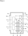
FIG. 3 is a side view depicting the interior of the outdoor unit in the refrigeration apparatus. -
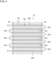
FIG. 4 is a schematic explanatory view of a first outdoor heat exchanger in the refrigeration apparatus. -
FIG. 5 is a schematic explanatory view of a second outdoor heat exchanger in the refrigeration apparatus. -
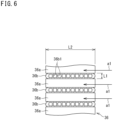
FIG. 6 is an enlarged sectional view of the second outdoor heat exchanger. -
FIG. 7 is an explanatory Mollier diagram on a refrigeration cycle of a first refrigerant circuit during cooling operation. - Embodiments of the present disclosure will be described in detail hereinafter with reference to the accompanying drawings.
-
FIG. 1 is a refrigerant circuit diagram of a refrigeration apparatus according to an embodiment of the present disclosure. - As depicted in
FIG. 1 , arefrigeration apparatus 10 according to the present embodiment is an air conditioner configured to adjust, to predetermined target temperature, air temperature in an indoor space as an air conditioning target space. Therefrigeration apparatus 10 according to the present embodiment is configured to cool and heat the indoor space. Therefrigeration apparatus 10 may alternatively be dedicated to cooling operation. Examples of therefrigeration apparatus 10 may include a refrigerator and a freezer configured to cool air in the apparatus. - The
refrigeration apparatus 10 includes an outdoor unit 11 (heat source unit) and an indoor unit 12 (utilization unit). Therefrigeration apparatus 10 exemplarily includes the singleoutdoor unit 11 and the singleindoor unit 12 connected to theoutdoor unit 11. Therefrigeration apparatus 10 may alternatively include a plurality ofindoor units 12 connected in parallel with theoutdoor unit 11. Therefrigeration apparatus 10 may still alternatively include a plurality ofoutdoor units 11. - The
refrigeration apparatus 10 includes afirst refrigerant circuit 21 and asecond refrigerant circuit 22. Thefirst refrigerant circuit 21 causes circulation of a first refrigerant whereas thesecond refrigerant circuit 22 causes circulation of a second refrigerant. The present embodiment adopts carbon dioxide as the first refrigerant. The present embodiment adopts, as the second refrigerant, a refrigerant having combustibility or toxicity, or a refrigerant having a high global warming potential (GWP). Examples of the second refrigerant include R290 (propane). Therefrigeration apparatus 10 further includes anauxiliary heat exchanger 27, acontrol device 51, anoutdoor fan 41, and anindoor fan 42. - The
first refrigerant circuit 21 causes circulation of the first refrigerant between theindoor unit 12 and theoutdoor unit 11. Thefirst refrigerant circuit 21 includes afirst compressor 24, a four-way switching valve 25, a first outdoor heat exchanger (heat source heat exchanger; first heat exchanger) 26, afirst expansion valve 28, afirst shutoff valve 29, an indoor heat exchanger (utilization heat exchanger) 30, asecond shutoff valve 31, afirst accumulator 32, arefrigerant pipe 40 connecting these components, and the like. - The
outdoor unit 11 includes thefirst compressor 24, the four-way switching valve 25, the firstoutdoor heat exchanger 26, thefirst expansion valve 28, thefirst shutoff valve 29, thesecond shutoff valve 31, and thefirst accumulator 32, which constitute thefirst refrigerant circuit 21. Theindoor unit 12 includes theindoor heat exchanger 30 constituting thefirst refrigerant circuit 21. Theoutdoor unit 11 is provided with theoutdoor fan 41 configured to import outdoor air into theoutdoor unit 11 and supply the firstoutdoor heat exchanger 26 with the outdoor air thus imported. Theindoor unit 12 is provided with theindoor fan 42 configured to import indoor air into theindoor unit 12 and supply theindoor heat exchanger 30 with the indoor air thus imported. - The
first compressor 24 sucks the first refrigerant in a low-pressure gas state and discharges the first refrigerant in a high-pressure gas state. Thefirst compressor 24 includes a motor having a number of operating revolutions adjustable in accordance with inverter control. Thefirst compressor 24 is of a variable capacity type (performance variable type) having capacity (performance) variable in accordance with inverter control of the motor. Thefirst compressor 24 may alternatively be of a constant capacity type. There may alternatively be provided a plurality offirst compressors 24. In this case, thefirst compressors 24 may include both a compressor of the variable capacity type and a compressor of the constant capacity type. - The four-
way switching valve 25 reverses a flow of the first refrigerant in therefrigerant pipe 40, and switchingly supplies one of the firstoutdoor heat exchanger 26 and theindoor heat exchanger 30 with the first refrigerant discharged from thefirst compressor 24. Therefrigeration apparatus 10 can thus switchingly execute cooling operation and heating operation. - The first
outdoor heat exchanger 26 is of a cross-fin tube type. The firstoutdoor heat exchanger 26 causes heat exchange between outdoor air imported by theoutdoor fan 41 and the first refrigerant to release heat from or evaporate the first refrigerant. The firstoutdoor heat exchanger 26 may be of a microchannel type similarly to a secondoutdoor heat exchanger 36 to be described later. - The
first expansion valve 28 is a decompressor configured to decompress to expand the first refrigerant. Thefirst expansion valve 28 is constituted by a motor valve configured to adjust a refrigerant flow rate or the like. Thefirst expansion valve 28 decompresses to expand the first refrigerant in a high-pressure gas state having radiated heat in the firstoutdoor heat exchanger 26 and theauxiliary heat exchanger 27 to be described later, to obtain a low-pressure refrigerant in a gas-liquid two-phase state. Thefirst expansion valve 28 functioning as a decompressor may be replaced with a capillary tube. - The
first shutoff valve 29 is a manually operated on-off valve. Thefirst shutoff valve 29 is closed to block the flow of the first refrigerant in therefrigerant pipe 40, and is opened to allow the flow of the first refrigerant in therefrigerant pipe 40. - The
indoor heat exchanger 30 is of the cross-fin tube type, the microchannel type, or the like. Theindoor heat exchanger 30 causes heat exchange between indoor air imported by theindoor fan 42 and the first refrigerant to release heat from or evaporate the first refrigerant. - The
second shutoff valve 31 is a manually operated on-off valve. Thesecond shutoff valve 31 is closed to block the flow of the first refrigerant in therefrigerant pipe 40, and is opened to allow the flow of the first refrigerant in therefrigerant pipe 40. - The
first accumulator 32 is provided on a suction pipe of thefirst compressor 24. Thefirst accumulator 32 temporarily reserves the first refrigerant in the low pressure state to be sucked into thefirst compressor 24 and separates the first refrigerant into a gas refrigerant and a liquid refrigerant. The first refrigerant as the gas refrigerant thus separated in thefirst accumulator 32 is sucked into thefirst compressor 24. - The second
refrigerant circuit 22 causes refrigerant circulation in theoutdoor unit 11. The secondrefrigerant circuit 22 adopts R290 (propane) as the second refrigerant. The secondrefrigerant circuit 22 includes asecond compressor 34, the second outdoor heat exchanger (second heat exchanger) 36, asecond expansion valve 38, asecond accumulator 39, arefrigerant pipe 50 connecting these components, and the like. - The
second compressor 34 sucks the second refrigerant in a low-pressure gas state and discharges the second refrigerant in a high-pressure gas state. Thesecond compressor 34 includes a motor having a number of operating revolutions adjustable in accordance with inverter control. Thesecond compressor 34 is of the variable capacity type (performance variable type) having capacity (performance) variable in accordance with inverter control of the motor. Thesecond compressor 34 may alternatively be of the constant capacity type. There may alternatively be provided a plurality ofsecond compressors 34. In this case, thesecond compressors 34 may include both a second compressor of the variable capacity type and a second compressor of the constant capacity type. - The second
outdoor heat exchanger 36 is of the microchannel type. The secondoutdoor heat exchanger 36 causes heat exchange between outdoor air supplied by theoutdoor fan 41 and a refrigerant to release heat from (condense) the refrigerant. - The
second expansion valve 38 is a decompressor configured to decompress to expand the second refrigerant. Thesecond expansion valve 38 according to the present embodiment is constituted by a motor valve configured to adjust a refrigerant flow rate or the like. Thesecond expansion valve 38 decompresses to expand the second refrigerant in a high pressure state having radiated heat in the secondoutdoor heat exchanger 36 to obtain a low-pressure refrigerant in a gas-liquid two-phase state. Thesecond expansion valve 38 functioning as a decompressor may be replaced with a capillary tube. - The
second accumulator 39 is provided on a suction pipe of thesecond compressor 34. Thesecond accumulator 39 temporarily reserves the second refrigerant in the low pressure state to be sucked into thesecond compressor 34 and separates the second refrigerant into a gas refrigerant and a liquid refrigerant. The second refrigerant as the gas refrigerant thus separated in thesecond accumulator 39 is sucked into thesecond compressor 34. - The auxiliary heat exchanger (third heat exchanger) 27 causes further heat radiation from the first refrigerant having radiated heat in the first
outdoor heat exchanger 26. Theauxiliary heat exchanger 27 evaporates the second refrigerant having radiated heat in the secondoutdoor heat exchanger 36 and having been decompressed in thesecond expansion valve 38. Theauxiliary heat exchanger 27 is exemplarily configured as a plate heat exchanger. - Specifically, the
auxiliary heat exchanger 27 includes a first heat transfer tube (first heat transfer flow path) 27a and a second heat transfer tube (second heat transfer flow path) 27b. The firstheat transfer tube 27a has a first end connected to a refrigerant pipe extending to the firstoutdoor heat exchanger 26. The firstheat transfer tube 27a has a second end connected to a refrigerant pipe extending to thefirst expansion valve 28. The secondheat transfer tube 27b has a first end connected to a refrigerant pipe extending to thesecond expansion valve 38. The secondheat transfer tube 27b has a second end connected to a refrigerant pipe extending to thesecond accumulator 39. - The
auxiliary heat exchanger 27 causes heat exchange between the first refrigerant flowing in the firstheat transfer tube 27a and the second refrigerant flowing in the secondheat transfer tube 27b. The firstheat transfer tube 27a receives the first refrigerant (gas refrigerant) having radiated heat in the firstoutdoor heat exchanger 26. The secondheat transfer tube 27b receives the second refrigerant (gas-liquid two-phase refrigerant) decompressed and expanded in thesecond expansion valve 38. - The
auxiliary heat exchanger 27 thus causes heat exchange between the first refrigerant having passed through the firstoutdoor heat exchanger 26 and flowing in the firstheat transfer tube 27a and the second refrigerant having passed through the second expansion valve (decompressor) 38 and flowing in the secondheat transfer tube 27b. Theauxiliary heat exchanger 27 radiates heat from the first refrigerant flowing in the firstheat transfer tube 27a and evaporates the second refrigerant flowing in the secondheat transfer tube 27b. - As described above, the
auxiliary heat exchanger 27 is included in the firstrefrigerant circuit 21 and the secondrefrigerant circuit 22. Theauxiliary heat exchanger 27 is thus regarded as a constituent element of both the firstrefrigerant circuit 21 and the secondrefrigerant circuit 22. - The
control device 51 controls behavior of thefirst compressor 24, the four-way switching valve 25, thefirst expansion valve 28, theoutdoor fan 41, theindoor fan 42, thesecond compressor 34, thesecond expansion valve 38, and the like. Thecontrol device 51 includes a processor and a memory. The processor of thecontrol device 51 is constituted by a central processing unit (CPU), an application specific integrated circuit (ASIC), a gate array, a field programmable gate array (FPGA), or the like. A programmable logic device such as the ASIC, the gate array, or the FPGA is configured to execute processing similarly to a control program. The memory of thecontrol device 51 includes a volatile memory such as a static random access memory (SRAM) or a dynamic random access memory (DRAM), or a nonvolatile memory such as a flash memory, a hard disk, or a read only memory (ROM). The nonvolatile memory stores a control program as a computer program, and control data. - The
control device 51 exhibits various functions when the processor executes the control program. Specifically, thecontrol device 51 executes a first mode for cooling operation and a second mode for heating operation. - When the
refrigeration apparatus 10 executes cooling operation, thecontrol device 51 drives both the firstrefrigerant circuit 21 and the secondrefrigerant circuit 22. The four-way switching valve 25 is kept in a state indicated by solid lines inFIG. 1 . Thefirst compressor 24 in the firstrefrigerant circuit 21 discharges the first refrigerant in a high-temperature high-pressure gas state. The first refrigerant flows into the firstoutdoor heat exchanger 26 by way of the four-way switching valve 25. The first refrigerant according to the present embodiment is carbon dioxide and is pressurized by thefirst compressor 24 to have pressure exceeding a critical point. The first refrigerant is caused by theoutdoor fan 41 to exchange heat with outdoor air and radiate heat. The first refrigerant further flows into theauxiliary heat exchanger 27. - Meanwhile, the
second compressor 34 in the secondrefrigerant circuit 22 discharges the second refrigerant in a high-temperature high-pressure gas state. The second refrigerant flows into the secondoutdoor heat exchanger 36 and is caused by theoutdoor fan 41 to exchange heat with outdoor air and release heat (condense). The second refrigerant further flows into thesecond expansion valve 38 to be decompressed to have predetermined low pressure. The second refrigerant thereafter flows into theauxiliary heat exchanger 27. - In the
auxiliary heat exchanger 27, the first refrigerant in the firstrefrigerant circuit 21 exchanges heat with the second refrigerant in the secondrefrigerant circuit 22 to radiate heat. The first refrigerant is then decompressed to be expanded in thefirst expansion valve 28, and flows into theindoor heat exchanger 30 of theindoor unit 12. In theindoor unit 12, the first refrigerant exchanges heat with indoor air to evaporate in theindoor heat exchanger 30. Theindoor fan 42 causes the indoor air cooled due to evaporation of the first refrigerant to blow indoors and cool the indoor space. The first refrigerant evaporated in theindoor heat exchanger 30 passes through therefrigerant pipe 40 to return to theoutdoor unit 11, and is sucked into thefirst compressor 24 by way of the four-way switching valve 25 and thefirst accumulator 32. - In the
auxiliary heat exchanger 27, the second refrigerant in the secondrefrigerant circuit 22 exchanges heat with the first refrigerant in the firstrefrigerant circuit 21 to evaporate. The second refrigerant is then sucked into thesecond compressor 34 by way of thesecond accumulator 39. - When the
refrigeration apparatus 10 executes heating operation, thecontrol device 51 drives the firstrefrigerant circuit 21 and stops the secondrefrigerant circuit 22. The four-way switching valve 25 is kept in a state indicated by broken lines inFIG. 1 . Thefirst compressor 24 discharges the first refrigerant in the high-temperature high-pressure gas state, which passes through the four-way switching valve 25 and flows into theindoor heat exchanger 30 of theindoor unit 12. In theindoor heat exchanger 30, the first refrigerant exchanges heat with indoor air to radiate heat. Theindoor fan 42 causes the indoor air heated due to heat radiation of the first refrigerant to blow indoors and heat the indoor space. - The first refrigerant then passes through the
refrigerant pipe 40, returns to theoutdoor unit 11, is decompressed to have predetermined low pressure in thefirst expansion valve 28, passes through theauxiliary heat exchanger 27, and flows into the firstoutdoor heat exchanger 26. The secondrefrigerant circuit 22 not being driven does not substantially cause heat exchange between the first refrigerant and the second refrigerant in theauxiliary heat exchanger 27. The first refrigerant having flowed into the firstoutdoor heat exchanger 26 exchanges heat with outdoor air to evaporate. The first refrigerant evaporated and gasified in the firstoutdoor heat exchanger 26 is sucked into thefirst compressor 24 by way of the four-way switching valve 25. - The
refrigeration apparatus 10 is configured to execute defrosting operation for removal of frost adhering to the firstoutdoor heat exchanger 26 due to heating operation. Similarly to cooling operation described above or the like, defrosting operation can be achieved by causing the first refrigerant having high temperature and high pressure to flow into the firstoutdoor heat exchanger 26. -
FIG. 7 is an explanatory Mollier diagram on a refrigeration cycle of the first refrigerant circuit during cooling operation.FIG. 7 includes reference sign L denoting an isothermal line at outdoor air temperature in summer or the like. - The first refrigerant used in the first
refrigerant circuit 21 is carbon dioxide and is pressurized to have pressure exceeding a critical point P by thefirst compressor 24. The first refrigerant radiates heat only enough to reach around outdoor air temperature in the firstoutdoor heat exchanger 26 during cooling operation, and can secure only an enthalpy difference Δh1 indicated inFIG. 7 . In the present embodiment, theauxiliary heat exchanger 27 causes heat exchange between the first refrigerant and the second refrigerant lower in temperature than outdoor air temperature, so that the first refrigerant further radiates heat to secure a further enthalpy difference Δh2. This enhances refrigerating capacity H of therefrigeration apparatus 10 adopting carbon dioxide as a refrigerant. - The
refrigerant pipe 40 may be detached from the firstrefrigerant circuit 21 for replacement of theindoor unit 12 or the like. The firstrefrigerant circuit 21 is opened in this case to possibly cause refrigerant leakage. The firstrefrigerant circuit 21 adopts carbon dioxide as the first refrigerant and is thus less affected by such leakage. In contrast, the secondrefrigerant circuit 22 is rarely opened because the second refrigerant circulates only in theoutdoor unit 11. The present embodiment adopts R290 (propane) having combustibility as the second refrigerant, but is less likely to have leakage because the secondrefrigerant circuit 22 is rarely opened. -
FIG. 2 is a plan view depicting the interior of the outdoor unit in the refrigeration apparatus.FIG. 3 is a side view depicting the interior of the outdoor unit in the refrigeration apparatus. - The
outdoor unit 11 includes acasing 55. Thecasing 55 has a rectangular parallelepiped shape. As depicted inFIG. 2 , thecasing 55 has the interior provided with a sectioningwall 56 zoning a machine chamber S1 and a heat exchange chamber S2. Thecasing 55 includes twoadjacent side walls side wall 55c that is disposed adjacent to theside wall 55b having the air intake port 55b1 and is provided with an air blow-out port 55c1. - The machine chamber S1 in the
casing 55 accommodates thefirst compressor 24, thesecond compressor 34, thefirst accumulator 32, thesecond accumulator 39, theauxiliary heat exchanger 27, and the like. The heat exchange chamber S2 in thecasing 55 accommodates the firstoutdoor heat exchanger 26, the secondoutdoor heat exchanger 36, theoutdoor fan 41, and the like. Theoutdoor fan 41 rotates about a shaft c. Theoutdoor fan 41 imports air into thecasing 55 via the air intake ports 55a1 and 55b1, and discharges air out of thecasing 55 via the air blow-out port 55c1.FIG. 2 andFIG. 3 include an arrow a indicating a flow direction of air imported to thecasing 55 via the air intake ports 55a1 and 55b1 and passing through the first and secondoutdoor heat exchangers casing 55 via the air blow-out port 55c1. - As depicted in
FIG. 2 , the firstoutdoor heat exchanger 26 has a substantially L shape in a top view. The firstoutdoor heat exchanger 26 is bent near a corner d between the twoside walls side walls - As depicted in
FIG. 2 , the secondoutdoor heat exchanger 36 has a substantially linear shape in a top view. The secondoutdoor heat exchanger 36 is disposed substantially along theside wall 55a of thecasing 55. In a top view, the secondoutdoor heat exchanger 36 is shorter than the firstoutdoor heat exchanger 26. - As depicted in
FIG. 3 , the secondoutdoor heat exchanger 36 is shorter in vertical length than the firstoutdoor heat exchanger 26. A lower end of the secondoutdoor heat exchanger 36 and a lower end of the firstoutdoor heat exchanger 26 are set on a bottom plate of thecasing 55 to be disposed substantially equally in height. The firstoutdoor heat exchanger 26 thus protrudes upward from the secondoutdoor heat exchanger 36. Accordingly, the firstoutdoor heat exchanger 26 is larger in air passage area than the secondoutdoor heat exchanger 36. - The first
outdoor heat exchanger 26 and the secondoutdoor heat exchanger 36 are supplied with air by the commonoutdoor fan 41. The secondoutdoor heat exchanger 36 is disposed downstream of the firstoutdoor heat exchanger 26 in an air flow direction a of theoutdoor fan 41. The secondoutdoor heat exchanger 36 is thus supplied with air having passed through the firstoutdoor heat exchanger 26. -
FIG. 4 is a schematic explanatory view of the first outdoor heat exchanger in the refrigeration apparatus. - The first
outdoor heat exchanger 26 includes a large number offins 26a and aheat transfer tube 26b. The large number offins 26a each have a rectangular plate shape in a side view, and are aligned parallel to one another. The large number offins 26a have plate surfaces extending vertically. - The
heat transfer tube 26b is a cylindrical tube having a circular section. Theheat transfer tube 26b is made of a material principally containing copper. Theheat transfer tube 26b is made of copper or a copper alloy. Theheat transfer tube 26b includes a plurality of linear tube portions 26b1 each having a linear shape and a curved tube portion 26b2 having a U shape. The linear tube portions 26b1 extend in a direction in which the large number offins 26a are aligned and penetrate thefins 26a. The curved tube portion 26b2 is disposed at each end portion of the firstoutdoor heat exchanger 26 in a top view, and connects the two linear tube portions 26b1 adjacent to each other. The plurality of linear tube portions 26b1 is disposed in a staggered arrangement in a vertical direction and in the air flow direction a as depicted inFIG. 3 . In a top view, the end portions of the firstoutdoor heat exchanger 26 are respectively provided withtube plates 26c. Thetube plates 26c keep the shape of the firstoutdoor heat exchanger 26. -
FIG. 5 is a schematic explanatory view of the second outdoor heat exchanger in the refrigeration apparatus.FIG. 6 is an enlarged sectional view of the second outdoor heat exchanger. - The second
outdoor heat exchanger 36 includes a large number offins 36a, a plurality ofheat transfer tubes 36b, andheaders heat transfer tubes 36b are made of a material principally containing aluminum. Theheat transfer tubes 36b are made of aluminum or an aluminum alloy. The plurality ofheat transfer tubes 36b is aligned vertically in parallel with each other. Theheat transfer tubes 36b are disposed substantially horizontally. - The
headers heat transfer tubes 36b. Theheaders liquid header 36c for a flow of a liquid refrigerant and agas header 36d for a flow of a gas refrigerant. Theheaders outdoor heat exchanger 36 into theheat transfer tubes 36b, and merge the second refrigerant from theheat transfer tubes 36b to send out of the secondoutdoor heat exchanger 36. - As depicted in
FIG. 6 , theheat transfer tubes 36b according to the present embodiment are constituted by porous tubes each provided therein with a plurality of refrigerant flow paths 36b1. The plurality of refrigerant flow paths 36b1 is aligned linearly in the air flow direction a. Theheat transfer tubes 36b each have a transverse section that is taken in a direction perpendicular to the longitudinal direction and lengthens in the air flow direction a in which the plurality ofrefrigerant 1 is aligned. In other words, each of theflow paths 36bheat transfer tubes 36b is a flat tube having a transverse section having a length L2 in the air flow direction a (horizontal direction) larger than a vertical length (thickness) L1. Hereinafter, theheat transfer tubes 36b of the secondoutdoor heat exchanger 36 will also be referred to as "flat multi-hole tubes". Each of the flatmulti-hole tubes 36b has an upper surface and a lower surface disposed substantially horizontally. - The flat
multi-hole tubes 36b each have the vertical length L1 exemplarily set to 1 mm to 3 mm. The flatmulti-hole tubes 36b each have the length L2 in the air flow direction a exemplarily set to 10 mm to 30 mm. In contrast, theheat transfer tube 26b of the firstoutdoor heat exchanger 26 has an outer diameter exemplarily set to 5 mm to 10 mm. Therefore, when viewed from the air flow direction a, the flatmulti-hole tube 36b has a smaller vertical length than theheat transfer tube 26b and has less resistance to the air flow. Each of the flatmulti-hole tubes 36b has the transverse section having the length L1 in the air flow direction a (horizontal direction) larger than the vertical length L2, and therefore water is likely to be accumulated on the upper surface. - Meanwhile, the
heat transfer tube 26b of the firstoutdoor heat exchanger 26 is larger in vertical length and thus higher in strength than the flatmulti-hole tubes 36b of the secondoutdoor heat exchanger 36. The firstoutdoor heat exchanger 26 according to the present embodiment is disposed closer to the outside (closer to theside walls outdoor unit 11 than the secondoutdoor heat exchanger 36. The firstoutdoor heat exchanger 26 higher in strength is disposed closer to the outside to inhibit damage to the first and secondoutdoor heat exchangers outdoor unit 11. - The refrigerant flow paths 36b1 in each of the flat
multi-hole tubes 36b of the secondoutdoor heat exchanger 36 is smaller in area than a refrigerant flow path in the heat transfer tube (cylindrical tube) 26b of the firstoutdoor heat exchanger 26. The secondoutdoor heat exchanger 36 thus has more opportunities of contact between the second refrigerant and the flatmulti-hole tubes 36b to achieve more efficient heat exchange in comparison to the firstoutdoor heat exchanger 26. This enables minimization of used quantity of the second refrigerant. The present embodiment adopts R290 (propane) having combustibility as the second refrigerant, and such a reduction of the second refrigerant is thus quite effective for a lower leakage risk. The used quantity of the second refrigerant can exemplarily be 1000 g or less. The used quantity of the second refrigerant can preferably be 150 g or less. - The
fins 36a of the secondoutdoor heat exchanger 36 are so-called corrugated fins. Thefins 36a are disposed between the flatmulti-hole tubes 36b vertically adjacent to each other. Each of thefins 36a is formed by bending a board into a wavy state. Each of thefins 36a thus extends in the longitudinal direction of the flatmulti-hole tubes 36b while being meandering upward and downward between the flatmulti-hole tubes 36b disposed above and below. Each of thefins 36a has an upper end and a lower end joined by brazing to the flatmulti-hole tubes 36b. Thecorrugated fins 36a each meander between the flatmulti-hole tubes 36b disposed above and below, and water once entered is hard to be drained. - The
refrigeration apparatus 10 according to the present embodiment operates only the firstrefrigerant circuit 21 and stops the secondrefrigerant circuit 22 during heating operation. Accordingly, the air flow generated by theoutdoor fan 41 exchanges heat with the first refrigerant flowing in the firstoutdoor heat exchanger 26 and simply passes through the secondoutdoor heat exchanger 36. Each of the flatmulti-hole tubes 36b of the secondoutdoor heat exchanger 36 has the transverse section long and narrow in the air flow direction a and has small resistance to the air flow, so as to inhibit deterioration in heat exchange efficiency in the firstoutdoor heat exchanger 26. - The second
outdoor heat exchanger 36 is not used for heating operation and is thus unlikely to generate frost in the secondoutdoor heat exchanger 36. Accordingly, water as molten frost is unlikely to be accumulated on the flatmulti-hole tubes 36b or in thecorrugated fins 36a or is unlikely to freeze. This can inhibit damage to bonded portions (brazed portions) between the flatmulti-hole tubes 36b and thecorrugated fins 36a by water entered thecorrugated fins 36a and frozen. Although the firstoutdoor heat exchanger 26 may generate frost during heating operation, water as molten frost due to defrosting operation or the like is thus hard to be accumulated on theheat transfer tube 26b. This can accordingly inhibit such water from refreezing. - The embodiment described above exemplifies R290 (propane) as the second refrigerant used in the second
refrigerant circuit 22. However, the present disclosure is not limited to this case. Any other refrigerant having combustibility or toxicity can be adopted as the second refrigerant. Alternatively, any refrigerant having a relatively high global warming potential (GWP) (such as a refrigerant having a higher GWP from 4 to 675 inclusive in comparison to a natural refrigerant) can be adopted as the second refrigerant. Examples of the refrigerant having combustibility can include R290 (propane) as mentioned above, as well as R32, R1234yf, R474a, and R600a (isobutane). Examples of the refrigerant having toxicity can include NH3 (ammonia). Examples of the refrigerant having a high GWP can include R32, R454B, and R454C. Among these, R32 has the largest GWP equal to 675. - The second
outdoor heat exchanger 36 may alternatively include the flatmulti-hole tubes 36b disposed vertically. For example, the secondoutdoor heat exchanger 36 depicted inFIG. 5 may be rotated by 90 degrees. Although water entered thecorrugated fins 36a is hard to be drained even in such a case, the secondoutdoor heat exchanger 36 functions as a radiator configured to release heat from the second refrigerant and does not function as an evaporator. This inhibits generation of frost, accumulation of water as molten frost, and freezing of water. - The second
outdoor heat exchanger 36 may alternatively include, instead of thecorrugated fins 36a, fins having a rectangular flat plate shape similarly to thefins 26a of the firstoutdoor heat exchanger 26. In this case, a large number of fins can be aligned along vertical direction and the flatmulti-hole tubes 36b can penetrate the plurality of fins. In this case, the fins may be cut off to expose an end portion in the air flow direction a of each of the flatmulti-hole tubes 36b. -
- (1) The
refrigeration apparatus 10 according to the above embodiment includes: the firstrefrigerant circuit 21 including the first heat exchanger (first outdoor heat exchanger) 26 configured to release heat from carbon dioxide serving as the first refrigerant; the secondrefrigerant circuit 22 including the second heat exchanger (second outdoor heat exchanger) 36 configured to release heat from the second refrigerant having combustibility or toxicity or the second refrigerant having the global warming potential (GWP) of four or more, and the decompressor (second expansion valve) 38 configured to decompress the second refrigerant; and the third heat exchanger (auxiliary heat exchanger) 27 configured to cause heat exchange between the first refrigerant having radiated heat in thefirst heat exchanger 26 and the second refrigerant having radiated heat in thesecond heat exchanger 36 and then decompressed in thedecompressor 38. Thesecond heat exchanger 36 includes the plurality of flatmulti-hole tubes 36b. - A heat exchanger including a flat multi-hole tube typically achieves more efficient heat exchange in comparison to a heat exchanger including a heat transfer tube having a general circular tube shape, and can thus reduce refrigerant used quantity. The
second heat exchanger 36 according to the above embodiment includes the flatmulti-hole tubes 36b and can thus be reduced in the used quantity of the second refrigerant having combustibility or toxicity or the second refrigerant having a GWP equal to four or more, for a lower leakage risk of the second refrigerant. - (2) The
refrigeration apparatus 10 according to the above embodiment further includes thecontrol device 51 configured to control operation of the firstrefrigerant circuit 21 and the secondrefrigerant circuit 22, and the fan (outdoor fan) 41 configured to generate an air flow to be supplied to thefirst heat exchanger 26 and thesecond heat exchanger 36. Thefirst heat exchanger 26 and thesecond heat exchanger 36 are aligned in the direction a of the air flow generated by thefan 41. Thecontrol device 51 executes the first mode (operating mode for cooling operation) of operating both the firstrefrigerant circuit 21 and the secondrefrigerant circuit 22 to cause thefirst heat exchanger 26 to release heat from the first refrigerant and cause thesecond heat exchanger 36 to release heat from the second refrigerant, and the second mode (operating mode for heating operation) of solely operating the firstrefrigerant circuit 21 to cause thefirst heat exchanger 26 to evaporate the first refrigerant. - In the second mode of solely operating the first
refrigerant circuit 21, the air flow generated by thefan 41 exchanges heat with the first refrigerant flowing in thefirst heat exchanger 26 and simply passes through thesecond heat exchanger 36. Each of the flatmulti-hole tubes 36b of thesecond heat exchanger 36 has the transverse section long and narrow in the air flow direction a and is hard to cause resistance to the air flow, so as to inhibit deterioration in heat exchange efficiency in thefirst heat exchanger 26. - (3) In the
refrigeration apparatus 10 according to the above embodiment, thesecond heat exchanger 36 includes the plurality of flatmulti-hole tubes 36b and the fin (corrugated fin) 36a meanderingly disposed between the flatmulti-hole tubes 36b adjacent to each other. - In the
second heat exchanger 36 including thefin 36a meandering between the adjacent flatmulti-hole tubes 36b, water entered thefin 36a is hard to be drained and accumulated water may be frozen to damage the bonded portions (brazed portions) between thecorrugated fin 36a and the flatmulti-hole tubes 36b. In therefrigeration apparatus 10 according to the present embodiment, thesecond heat exchanger 36 functions as a radiator and thus inhibits generation of frost and accumulation of water as molten frost. The corrugated fin has high heat exchange efficiency and can further reduce the refrigerant used quantity. - (4) The
refrigeration apparatus 10 according to the above embodiment uses the second refrigerant in the quantity of 1000 g or less in the secondrefrigerant circuit 22. Thesecond heat exchanger 36 including the flatmulti-hole tubes 36b described above achieves more efficient heat exchange in comparison to thefirst heat exchanger 26 including theheat transfer tube 26b having the circular tube shape, and can thus reduce the refrigerant used quantity to 1000 g or less. This can lower the leakage risk for the second refrigerant. - (5) The
refrigeration apparatus 10 according to the above embodiment use the second refrigerant in the quantity of 150 g or less in the secondrefrigerant circuit 22. Thesecond heat exchanger 36 including the flatmulti-hole tubes 36b described above achieves more efficient heat exchange in comparison to thefirst heat exchanger 26 including theheat transfer tube 26b having the circular tube shape, and can thus reduce the refrigerant used quantity to 150 g or less. This can further lower the leakage risk for the second refrigerant. - The embodiments have been described above. Various changes to modes and details will be available without departing from the object and the scope of the claims.
-
- 10
- refrigeration apparatus
- 21
- first refrigerant circuit
- 22
- second refrigerant circuit
- 26
- first outdoor heat exchanger (first heat exchanger)
- 27
- auxiliary heat exchanger (third heat exchanger)
- 36
- second outdoor heat exchanger (second heat exchanger)
- 36a
- corrugated fin
- 36b
- flat multi-hole tube
- 38
- second expansion valve (decompressor)
- 41
- outdoor fan
- 51
- control device
- a
- air flow direction
Claims (5)
- A refrigeration apparatus comprising:a first refrigerant circuit (21) including a first heat exchanger (26) configured to release heat from carbon dioxide serving as a first refrigerant;a second refrigerant circuit (22) including a second heat exchanger (36) configured to release heat from a second refrigerant having combustibility or toxicity or a second refrigerant having a global warming potential equal to four or more, and a decompressor (38) configured to decompress the second refrigerant; anda third heat exchanger (27) configured to cause heat exchange between the first refrigerant having radiated heat in the first heat exchanger (26) and the second refrigerant having radiated heat in the second heat exchanger (36) and then decompressed in the decompressor (38); whereinthe second heat exchanger (36) includes a plurality of flat multi-hole tubes (36b).
- The refrigeration apparatus according to claim 1, further comprisinga control device (51) configured to control operation of the first refrigerant circuit (21) and the second refrigerant circuit (22), and a fan (41) configured to generate an air flow to be supplied to the first heat exchanger (26) and the second heat exchanger (36), whereinthe first heat exchanger (26) and the second heat exchanger (36) are aligned in a direction (a) of the air flow generated by the fan (41), andthe control device (51) executes a first mode of operating both the first refrigerant circuit (21) and the second refrigerant circuit (22) to cause the first heat exchanger (26) to release heat from the first refrigerant and cause the second heat exchanger (36) to release heat from the second refrigerant, and a second mode of solely operating the first refrigerant circuit (21) to cause the first heat exchanger (26) to evaporate the first refrigerant.
- The refrigeration apparatus according to claim 1 or 2, wherein
the second heat exchanger (36) includes the plurality of flat multi-hole tubes (36b), and a fin (36a) meanderingly disposed between the flat multi-hole tubes (36b) adjacent to each other. - The refrigeration apparatus according to any one of claims 1 to 3, wherein the second refrigerant circuit (22) uses the second refrigerant in a quantity of 1000 g or less.
- The refrigeration apparatus according to claim 4, wherein the second refrigerant circuit (22) uses the second refrigerant in a quantity of 150 g or less.
Applications Claiming Priority (2)
| Application Number | Priority Date | Filing Date | Title |
|---|---|---|---|
| JP2023109483A JP2025007831A (en) | 2023-07-03 | 2023-07-03 | Refrigeration equipment |
| PCT/JP2024/020517 WO2025009312A1 (en) | 2023-07-03 | 2024-06-05 | Refrigeration device |
Publications (2)
| Publication Number | Publication Date |
|---|---|
| EP4513110A1 true EP4513110A1 (en) | 2025-02-26 |
| EP4513110A4 EP4513110A4 (en) | 2025-06-18 |
Family
ID=93333877
Family Applications (1)
| Application Number | Title | Priority Date | Filing Date |
|---|---|---|---|
| EP24790249.7A Pending EP4513110A4 (en) | 2023-07-03 | 2024-06-05 | COOLING DEVICE |
Country Status (5)
| Country | Link |
|---|---|
| US (1) | US20260078938A1 (en) |
| EP (1) | EP4513110A4 (en) |
| JP (1) | JP2025007831A (en) |
| CN (1) | CN121443898A (en) |
| WO (1) | WO2025009312A1 (en) |
Family Cites Families (8)
| Publication number | Priority date | Publication date | Assignee | Title |
|---|---|---|---|---|
| JP4856846B2 (en) * | 2003-10-24 | 2012-01-18 | 古河スカイ株式会社 | Resin-coated aluminum flat multi-hole tube for automobile heat exchanger excellent in brazing and method for producing the same |
| CN1886625B (en) * | 2003-11-28 | 2010-12-01 | 三菱电机株式会社 | Refrigeration and air conditioning units |
| JP5629280B2 (en) * | 2012-03-02 | 2014-11-19 | 株式会社日立製作所 | Waste heat recovery system and operation method thereof |
| JP2014074508A (en) * | 2012-10-02 | 2014-04-24 | Samsung R&D Institute Japan Co Ltd | Cascade heat exchanger |
| JP2020201013A (en) * | 2019-06-12 | 2020-12-17 | ダイキン工業株式会社 | air conditioner |
| WO2021014865A1 (en) * | 2019-07-22 | 2021-01-28 | Phcホールディングス株式会社 | Refrigeration apparatus |
| JP7235998B1 (en) * | 2021-09-30 | 2023-03-09 | ダイキン工業株式会社 | Cascade unit and refrigeration cycle equipment |
| JP7265193B2 (en) * | 2021-09-30 | 2023-04-26 | ダイキン工業株式会社 | Cascade unit and refrigeration cycle equipment |
-
2023
- 2023-07-03 JP JP2023109483A patent/JP2025007831A/en active Pending
-
2024
- 2024-06-05 EP EP24790249.7A patent/EP4513110A4/en active Pending
- 2024-06-05 CN CN202480043340.4A patent/CN121443898A/en active Pending
- 2024-06-05 WO PCT/JP2024/020517 patent/WO2025009312A1/en not_active Ceased
-
2025
- 2025-11-28 US US19/403,306 patent/US20260078938A1/en active Pending
Also Published As
| Publication number | Publication date |
|---|---|
| JP2025007831A (en) | 2025-01-17 |
| EP4513110A4 (en) | 2025-06-18 |
| CN121443898A (en) | 2026-01-30 |
| WO2025009312A1 (en) | 2025-01-09 |
| US20260078938A1 (en) | 2026-03-19 |
Similar Documents
| Publication | Publication Date | Title |
|---|---|---|
| KR100958399B1 (en) | HACC unit using subcooler | |
| EP2672203A1 (en) | Air-conditioning device | |
| WO2010119591A1 (en) | Freezer-refrigerator and cooling storage unit | |
| US11506431B2 (en) | Refrigeration cycle apparatus | |
| CN111065868B (en) | Heat exchanger unit and refrigeration cycle device | |
| JP2021055957A (en) | Evaporator, and refrigeration cycle device including the same | |
| CN114811768A (en) | Air conditioner and heat exchanger | |
| JP4608303B2 (en) | Vapor compression heat pump | |
| US20050247077A1 (en) | Evaporator for a refrigeration system | |
| US20260078938A1 (en) | Refrigeration apparatus | |
| JP6091567B2 (en) | Refrigerator and refrigeration equipment | |
| KR100883600B1 (en) | Air conditioner | |
| JP7154420B2 (en) | refrigeration cycle equipment | |
| CN219014673U (en) | Refrigerating system, air conditioner and refrigeration house | |
| JP6298992B2 (en) | Air conditioner | |
| JP6925508B2 (en) | Heat exchanger, refrigeration cycle device and air conditioner | |
| WO2021065914A1 (en) | Freezing apparatus | |
| EP4513106A1 (en) | Refrigeration device | |
| WO2020235030A1 (en) | Heat exchanger and refrigeration cycle device using same | |
| JP7258212B2 (en) | air conditioner | |
| US20240230167A9 (en) | Refrigeration cycle apparatus | |
| WO2025013244A1 (en) | Outdoor unit for air conditioner and air conditioner comprising same | |
| US20250123034A1 (en) | Heat exchanger and refrigeration cycle apparatus | |
| Ariyadi et al. | R-32 and R-134a as Refrigerants for Fisheries Cold Storage: An Energy Performance Analysis | |
| KR200243044Y1 (en) | Heat Exchanger For Air Conditioning Of Refrigerator |
Legal Events
| Date | Code | Title | Description |
|---|---|---|---|
| STAA | Information on the status of an ep patent application or granted ep patent |
Free format text: STATUS: UNKNOWN |
|
| STAA | Information on the status of an ep patent application or granted ep patent |
Free format text: STATUS: THE INTERNATIONAL PUBLICATION HAS BEEN MADE |
|
| PUAI | Public reference made under article 153(3) epc to a published international application that has entered the european phase |
Free format text: ORIGINAL CODE: 0009012 |
|
| STAA | Information on the status of an ep patent application or granted ep patent |
Free format text: STATUS: REQUEST FOR EXAMINATION WAS MADE |
|
| 17P | Request for examination filed |
Effective date: 20241023 |
|
| AK | Designated contracting states |
Kind code of ref document: A1 Designated state(s): AL AT BE BG CH CY CZ DE DK EE ES FI FR GB GR HR HU IE IS IT LI LT LU LV MC ME MK MT NL NO PL PT RO RS SE SI SK SM TR |
|
| A4 | Supplementary search report drawn up and despatched |
Effective date: 20250515 |
|
| RIC1 | Information provided on ipc code assigned before grant |
Ipc: F28F 1/32 20060101ALI20250509BHEP Ipc: F25B 9/00 20060101ALI20250509BHEP Ipc: F25B 13/00 20060101ALI20250509BHEP Ipc: F28D 1/053 20060101ALI20250509BHEP Ipc: F28F 1/12 20060101ALI20250509BHEP Ipc: F28D 1/047 20060101ALI20250509BHEP Ipc: F25B 49/02 20060101ALI20250509BHEP Ipc: F25B 39/00 20060101ALI20250509BHEP Ipc: F28F 1/02 20060101ALI20250509BHEP Ipc: F25B 39/04 20060101ALI20250509BHEP Ipc: F25B 1/00 20060101ALI20250509BHEP Ipc: F25B 7/00 20060101AFI20250509BHEP |
|
| P01 | Opt-out of the competence of the unified patent court (upc) registered |
Free format text: CASE NUMBER: UPC_APP_3794_4513110/2025 Effective date: 20250820 |
|
| STAA | Information on the status of an ep patent application or granted ep patent |
Free format text: STATUS: EXAMINATION IS IN PROGRESS |
|
| 17Q | First examination report despatched |
Effective date: 20260203 |