EP4513109A1 - Refrigeration device - Google Patents
Refrigeration device Download PDFInfo
- Publication number
- EP4513109A1 EP4513109A1 EP24789705.1A EP24789705A EP4513109A1 EP 4513109 A1 EP4513109 A1 EP 4513109A1 EP 24789705 A EP24789705 A EP 24789705A EP 4513109 A1 EP4513109 A1 EP 4513109A1
- Authority
- EP
- European Patent Office
- Prior art keywords
- heat exchanger
- refrigerant
- refrigeration apparatus
- heat
- air flow
- Prior art date
- Legal status (The legal status is an assumption and is not a legal conclusion. Google has not performed a legal analysis and makes no representation as to the accuracy of the status listed.)
- Pending
Links
Images




Classifications
-
- F—MECHANICAL ENGINEERING; LIGHTING; HEATING; WEAPONS; BLASTING
- F25—REFRIGERATION OR COOLING; COMBINED HEATING AND REFRIGERATION SYSTEMS; HEAT PUMP SYSTEMS; MANUFACTURE OR STORAGE OF ICE; LIQUEFACTION SOLIDIFICATION OF GASES
- F25B—REFRIGERATION MACHINES, PLANTS OR SYSTEMS; COMBINED HEATING AND REFRIGERATION SYSTEMS; HEAT PUMP SYSTEMS
- F25B7/00—Compression machines, plants or systems, with cascade operation, i.e. with two or more circuits, the heat from the condenser of one circuit being absorbed by the evaporator of the next circuit
-
- F—MECHANICAL ENGINEERING; LIGHTING; HEATING; WEAPONS; BLASTING
- F25—REFRIGERATION OR COOLING; COMBINED HEATING AND REFRIGERATION SYSTEMS; HEAT PUMP SYSTEMS; MANUFACTURE OR STORAGE OF ICE; LIQUEFACTION SOLIDIFICATION OF GASES
- F25B—REFRIGERATION MACHINES, PLANTS OR SYSTEMS; COMBINED HEATING AND REFRIGERATION SYSTEMS; HEAT PUMP SYSTEMS
- F25B13/00—Compression machines, plants or systems, with reversible cycle
-
- F—MECHANICAL ENGINEERING; LIGHTING; HEATING; WEAPONS; BLASTING
- F25—REFRIGERATION OR COOLING; COMBINED HEATING AND REFRIGERATION SYSTEMS; HEAT PUMP SYSTEMS; MANUFACTURE OR STORAGE OF ICE; LIQUEFACTION SOLIDIFICATION OF GASES
- F25D—REFRIGERATORS; COLD ROOMS; ICE-BOXES; COOLING OR FREEZING APPARATUS NOT OTHERWISE PROVIDED FOR
- F25D17/00—Arrangements for circulating cooling fluids; Arrangements for circulating gas, e.g. air, within refrigerated spaces
- F25D17/04—Arrangements for circulating cooling fluids; Arrangements for circulating gas, e.g. air, within refrigerated spaces for circulating air, e.g. by convection
- F25D17/06—Arrangements for circulating cooling fluids; Arrangements for circulating gas, e.g. air, within refrigerated spaces for circulating air, e.g. by convection by forced circulation
- F25D17/067—Evaporator fan units
-
- F—MECHANICAL ENGINEERING; LIGHTING; HEATING; WEAPONS; BLASTING
- F28—HEAT EXCHANGE IN GENERAL
- F28D—HEAT-EXCHANGE APPARATUS, NOT PROVIDED FOR IN ANOTHER SUBCLASS, IN WHICH THE HEAT-EXCHANGE MEDIA DO NOT COME INTO DIRECT CONTACT
- F28D1/00—Heat-exchange apparatus having stationary conduit assemblies for one heat-exchange medium only, the media being in contact with different sides of the conduit wall, in which the other heat-exchange medium is a large body of fluid, e.g. domestic or motor car radiators
- F28D1/02—Heat-exchange apparatus having stationary conduit assemblies for one heat-exchange medium only, the media being in contact with different sides of the conduit wall, in which the other heat-exchange medium is a large body of fluid, e.g. domestic or motor car radiators with heat-exchange conduits immersed in the body of fluid
- F28D1/04—Heat-exchange apparatus having stationary conduit assemblies for one heat-exchange medium only, the media being in contact with different sides of the conduit wall, in which the other heat-exchange medium is a large body of fluid, e.g. domestic or motor car radiators with heat-exchange conduits immersed in the body of fluid with tubular conduits
- F28D1/0408—Multi-circuit heat exchangers, e.g. integrating different heat exchange sections in the same unit or heat exchangers for more than two fluids
- F28D1/0426—Multi-circuit heat exchangers, e.g. integrating different heat exchange sections in the same unit or heat exchangers for more than two fluids with units having particular arrangement relative to the large body of fluid, e.g. with interleaved units or with adjacent heat exchange units in common air flow or with units extending at an angle to each other or with units arranged around a central element
- F28D1/0435—Combination of units extending one behind the other
-
- F—MECHANICAL ENGINEERING; LIGHTING; HEATING; WEAPONS; BLASTING
- F28—HEAT EXCHANGE IN GENERAL
- F28D—HEAT-EXCHANGE APPARATUS, NOT PROVIDED FOR IN ANOTHER SUBCLASS, IN WHICH THE HEAT-EXCHANGE MEDIA DO NOT COME INTO DIRECT CONTACT
- F28D1/00—Heat-exchange apparatus having stationary conduit assemblies for one heat-exchange medium only, the media being in contact with different sides of the conduit wall, in which the other heat-exchange medium is a large body of fluid, e.g. domestic or motor car radiators
- F28D1/02—Heat-exchange apparatus having stationary conduit assemblies for one heat-exchange medium only, the media being in contact with different sides of the conduit wall, in which the other heat-exchange medium is a large body of fluid, e.g. domestic or motor car radiators with heat-exchange conduits immersed in the body of fluid
- F28D1/04—Heat-exchange apparatus having stationary conduit assemblies for one heat-exchange medium only, the media being in contact with different sides of the conduit wall, in which the other heat-exchange medium is a large body of fluid, e.g. domestic or motor car radiators with heat-exchange conduits immersed in the body of fluid with tubular conduits
- F28D1/047—Heat-exchange apparatus having stationary conduit assemblies for one heat-exchange medium only, the media being in contact with different sides of the conduit wall, in which the other heat-exchange medium is a large body of fluid, e.g. domestic or motor car radiators with heat-exchange conduits immersed in the body of fluid with tubular conduits the conduits being bent, e.g. in a serpentine or zig-zag
- F28D1/0477—Heat-exchange apparatus having stationary conduit assemblies for one heat-exchange medium only, the media being in contact with different sides of the conduit wall, in which the other heat-exchange medium is a large body of fluid, e.g. domestic or motor car radiators with heat-exchange conduits immersed in the body of fluid with tubular conduits the conduits being bent, e.g. in a serpentine or zig-zag the conduits being bent in a serpentine or zig-zag
-
- F—MECHANICAL ENGINEERING; LIGHTING; HEATING; WEAPONS; BLASTING
- F28—HEAT EXCHANGE IN GENERAL
- F28F—DETAILS OF HEAT-EXCHANGE AND HEAT-TRANSFER APPARATUS, OF GENERAL APPLICATION
- F28F1/00—Tubular elements; Assemblies of tubular elements
- F28F1/10—Tubular elements and assemblies thereof with means for increasing heat-transfer area, e.g. with fins, with projections, with recesses
- F28F1/12—Tubular elements and assemblies thereof with means for increasing heat-transfer area, e.g. with fins, with projections, with recesses the means being only outside the tubular element
- F28F1/24—Tubular elements and assemblies thereof with means for increasing heat-transfer area, e.g. with fins, with projections, with recesses the means being only outside the tubular element and extending transversely
- F28F1/32—Tubular elements and assemblies thereof with means for increasing heat-transfer area, e.g. with fins, with projections, with recesses the means being only outside the tubular element and extending transversely the means having portions engaging further tubular elements
- F28F1/325—Fins with openings
-
- F—MECHANICAL ENGINEERING; LIGHTING; HEATING; WEAPONS; BLASTING
- F24—HEATING; RANGES; VENTILATING
- F24F—AIR-CONDITIONING; AIR-HUMIDIFICATION; VENTILATION; USE OF AIR CURRENTS FOR SCREENING
- F24F1/00—Room units for air-conditioning, e.g. separate or self-contained units or units receiving primary air from a central station
- F24F1/06—Separate outdoor units, e.g. outdoor unit to be linked to a separate room comprising a compressor and a heat exchanger
- F24F1/14—Heat exchangers specially adapted for separate outdoor units
- F24F1/16—Arrangement or mounting thereof
-
- F—MECHANICAL ENGINEERING; LIGHTING; HEATING; WEAPONS; BLASTING
- F25—REFRIGERATION OR COOLING; COMBINED HEATING AND REFRIGERATION SYSTEMS; HEAT PUMP SYSTEMS; MANUFACTURE OR STORAGE OF ICE; LIQUEFACTION SOLIDIFICATION OF GASES
- F25B—REFRIGERATION MACHINES, PLANTS OR SYSTEMS; COMBINED HEATING AND REFRIGERATION SYSTEMS; HEAT PUMP SYSTEMS
- F25B2313/00—Compression machines, plants or systems with reversible cycle not otherwise provided for
- F25B2313/025—Compression machines, plants or systems with reversible cycle not otherwise provided for using multiple outdoor units
- F25B2313/0254—Compression machines, plants or systems with reversible cycle not otherwise provided for using multiple outdoor units in series arrangements
-
- F—MECHANICAL ENGINEERING; LIGHTING; HEATING; WEAPONS; BLASTING
- F25—REFRIGERATION OR COOLING; COMBINED HEATING AND REFRIGERATION SYSTEMS; HEAT PUMP SYSTEMS; MANUFACTURE OR STORAGE OF ICE; LIQUEFACTION SOLIDIFICATION OF GASES
- F25B—REFRIGERATION MACHINES, PLANTS OR SYSTEMS; COMBINED HEATING AND REFRIGERATION SYSTEMS; HEAT PUMP SYSTEMS
- F25B39/00—Evaporators; Condensers
- F25B39/04—Condensers
-
- F—MECHANICAL ENGINEERING; LIGHTING; HEATING; WEAPONS; BLASTING
- F28—HEAT EXCHANGE IN GENERAL
- F28D—HEAT-EXCHANGE APPARATUS, NOT PROVIDED FOR IN ANOTHER SUBCLASS, IN WHICH THE HEAT-EXCHANGE MEDIA DO NOT COME INTO DIRECT CONTACT
- F28D21/00—Heat-exchange apparatus not covered by any of the groups F28D1/00 - F28D20/00
- F28D2021/0019—Other heat exchangers for particular applications; Heat exchange systems not otherwise provided for
- F28D2021/0068—Other heat exchangers for particular applications; Heat exchange systems not otherwise provided for for refrigerant cycles
Definitions
- the present disclosure relates to a refrigeration apparatus.
- a refrigeration apparatus including a unit having a first refrigerant circuit configured to exhibit main cooling capability, a second refrigerant circuit configured to assist the first refrigerant circuit in the cooling capability, and a heat exchanger configured to cause heat exchange between a first refrigerant in the first refrigerant circuit and a second refrigerant in the second refrigerant circuit (see PATENT LITERATURE 1).
- the first refrigerant and the second refrigerant are different from each other in terms of refrigerant types in the refrigeration apparatus.
- a first air heat exchanger included in the first refrigerant circuit and a second air heat exchanger included in the second refrigerant circuit may be aligned windward and leeward in an air flow direction of air subject to heat exchange.
- the second air heat exchanger is disposed windward of the first air heat exchanger, the second air heat exchanger is disposed at an outermost location in the unit.
- external force or the like is likely to be applied to the second air heat exchanger during conveyance, and the second air heat exchanger is thus likely to be damaged.
- the refrigeration apparatus includes the first heat exchanger adopting the circular tube as a heat transfer tube, and the second heat exchanger adopting the flat multi-hole tube as a heat transfer tube.
- the flat multi-hole tube is weaker against external force than the circular tube.
- the first heat exchanger is disposed windward of the second heat exchanger in the air flow direction, to dispose the first heat exchanger outside the second heat exchanger.
- the first heat exchanger including the circular tube as a heat transfer tube is disposed windward of the second heat exchanger including the flat multi-hole tube as a heat transfer tube in the air flow direction, so as to reduce risk of damage to the second heat exchanger when external force is applied to a unit including the first heat exchanger and the second heat exchanger.
- the second heat exchanger is constituted by a heat exchanger including a plurality of the flat multi-hole tubes, and a fin meanderingly disposed between the flat multi-hole tubes adjacent to each other.
- the flat multi-hole tubes and the fin are flush with each other and the flat multi-hole tubes are thus not protected by the fin. Accordingly, the flat multi-hole tubes are likely to directly receive external force to be damaged in the heat exchanger configured as described above.
- the refrigeration apparatus according to the present disclosure can reduce risk of damage to the flat multi-hole tubes when the heat exchanger configured as described above is adopted as the second heat exchanger.
- the refrigeration apparatus according to the present disclosure adopts the heat exchanger configured as described above to reduce used quantity of the second refrigerant.
- the fan is disposed leeward of the second heat exchanger in the air flow direction, and the second heat exchanger is fixed to a support configured to support the fan.
- the fan is disposed leeward of the second heat exchanger in the air flow direction.
- the refrigeration apparatus according to the present disclosure can accordingly fix the second heat exchanger with use of the support configured to fix the fan.
- the first heat exchanger includes a first region overlapped with the second heat exchanger when viewed in the air flow direction, and a second region not overlapped with the second heat exchanger when viewed in the air flow direction.
- the two heat exchangers in a case where outer shapes of the heat exchangers are dimensionally equal and positionally identical when viewed in the air flow direction, the two heat exchangers can be easily supported by a common support. In another case where the outer shapes of the two heat exchangers are dimensionally different from each other and misaligned when viewed in the air flow direction, the two heat exchangers are difficult to be supported by a common support. Even if the first heat exchanger includes the first region overlapped with the second heat exchanger and the second region not overlapped with the second heat exchanger when viewed in the air flow direction, the refrigeration apparatus according to the present disclosure can fix the second heat exchanger with use of the support configured to fix the fan.
- an area of a fourth region zoned by an outer shape of the second heat exchanger is smaller than an area of a third region zoned by an outer shape of the first heat exchanger, and the third region includes the fourth region.
- the two heat exchangers in a case where the outer shapes of the two heat exchangers are dimensionally equal to each other, the two heat exchangers can be easily supported by a common support. In another case where the outer shapes of the two heat exchangers are dimensionally different from each other, the heat exchanger dimensionally larger can be easily supported by a frame of a case accommodating this heat exchanger, but the heat exchanger dimensionally smaller is difficult to be supported by the frame of the case.
- the second heat exchanger can be fixed by the support configured to fix the fan.
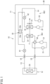
- FIG. 1 is an explanatory view of refrigerant circuits in a refrigeration apparatus according to an embodiment of the present disclosure.
- the present disclosure provides a refrigeration apparatus 10 including a heat source-side unit 11, a utilization-side unit 12, a refrigerant pipe 13 connecting the heat source-side unit 11 and the utilization-side unit 12, and a fan 15.
- the refrigeration apparatus 10 exemplified in the present embodiment is an air conditioner configured to condition air in a target space with use of the utilization-side unit 12.
- the refrigeration apparatus 10 is an air conditioner of a separate type separately including the heat source-side unit (outdoor unit) 11 and the utilization-side unit (indoor unit) 12.
- the present embodiment exemplifies the air conditioner as the refrigeration apparatus 10, although the refrigeration apparatus according to the present disclosure may be a refrigerated case or the like, without being limited to the air conditioner.
- the refrigerant pipe 13 includes a gate valve 18 disposed at each of portions entering and exiting a case of the heat source-side unit 11.
- the heat source-side unit 11 includes a first compressor 21, a second compressor 22, a first heat exchanger 31, a second heat exchanger 32, a third heat exchanger 33, a first expansion valve 41, a second expansion valve 42, a four-way switching valve 50, a first accumulator 51, and a second accumulator 52.
- the utilization-side unit 12 includes a utilization-side heat exchanger 34.
- the refrigeration apparatus 10 includes a first refrigerant circuit RC1 including the first compressor 21, the first heat exchanger 31, the first expansion valve 41, the utilization-side heat exchanger 34, and the refrigerant pipe 13 connecting these devices, and a second refrigerant circuit RC2 including the second compressor 22, the second heat exchanger 32, the second expansion valve 42, and a refrigerant pipe 14 connecting these devices.
- the first refrigerant circuit RC1 uses a first refrigerant R1 as a refrigerant and is configured to execute refrigeration cycle operation.
- the second refrigerant circuit RC2 uses a second refrigerant R2 as a refrigerant different from the first refrigerant R1 and is configured to execute refrigeration cycle operation.
- Each of the first compressor 21 and the second compressor 22 sucks a low-pressure gas refrigerant and discharges a high-pressure gas refrigerant.
- Each of the first compressor 21 and the second compressor 22 includes a motor (not depicted) having a number of operating revolutions adjustable through inverter control.
- Each of the first compressor 21 and the second compressor 22 is of a variable capacity type (capability variable type) having capacity (capability) variable through inverter control of the motor.
- Each of the first compressor 21 and the second compressor 22 may alternatively be of a constant capacity type.
- the four-way switching valve 50 is configured to reverse a flow of the first refrigerant R1 in the refrigerant pipe 13 of the first refrigerant circuit RC1, and switchingly supply one of the first heat exchanger 31 and the utilization-side heat exchanger 34 with the first refrigerant R1 discharged from the first compressor 21.
- the refrigeration apparatus 10 is configured to switch between cooling operation and heating operation by switching a flow direction of the first refrigerant R1 with use of the four-way switching valve 50.
- the refrigeration apparatus 10 according to the present embodiment may alternatively include no four-way switching valve, and may be used exclusively for cooling.
- the first expansion valve 41 is constituted by a motor valve configured to adjust a flow rate of the first refrigerant R1.
- a control device included in the refrigeration apparatus 10 adjusts an opening degree of the first expansion valve 41 to adjust cooling capability exhibited by the first refrigerant circuit RC1.
- the control device in the refrigeration apparatus 10 maximizes the opening degree of the first expansion valve 41.
- the second expansion valve 42 is constituted by a motor valve configured to adjust a flow rate of the second refrigerant R2.
- the control device (not depicted) in the refrigeration apparatus 10 adjusts an opening degree of the second expansion valve 42 to adjust cooling capability exhibited by the second refrigerant circuit RC2.
- the refrigeration apparatus 10 causes heat exchange between the first refrigerant R1 and the second refrigerant R2 in the third heat exchanger 33 to assist cooling capability of the first refrigerant circuit RC1 with cooling capability of the second refrigerant circuit RC2.
- the control device (not depicted) in the refrigeration apparatus 10 adjusts the opening degree of the second expansion valve 42 to adjust heat exchange quantity between the first refrigerant R1 and the second refrigerant R2.
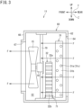
- FIG. 2 is an explanatory sectional plan view of the heat source-side unit in the refrigeration apparatus.
- FIG. 3 is an explanatory sectional side view of the heat source-side unit in the refrigeration apparatus.
- the following description includes expressions of up, down, front, rear, left, and right, which follow arrows indicated in FIG. 2 and FIG. 3 .
- FIG. 2 , FIG. 3 and the like include arrows X, Y, and Z perpendicular to one another.
- the arrow X indicates a direction (first direction) assumed as a lateral direction
- the arrow Y indicates a direction (second direction) assumed as an anteroposterior direction
- the arrow Z indicates a direction (third direction) assumed as a vertical direction.
- the lateral direction will also be referred to as a first direction X
- the anteroposterior direction will also be referred to as a second direction Y
- the vertical direction will also be referred to as a third direction Z.
- the direction X may be assumed as the anteroposterior direction
- the direction Y may be assumed as the lateral direction.
- the heat source-side unit 11 includes a case 60.
- the case 60 has a rectangular parallelepiped shape, and has a rectangular shape in a planar view.
- the case 60 has an interior provided with a sectioning wall 61 zoning a machine chamber S1 and a heat exchange chamber S2.
- the case 60 includes two adjacent side walls 62 and 63 disposed at the heat exchange chamber S2 and provided with air intake ports 64 and 65, respectively.
- the machine chamber S1 accommodates the first compressor 21, the second compressor 22, the third heat exchanger 33, the first accumulator 51, and the second accumulator 52.
- the machine chamber S1 further accommodates, in addition to the above, the four-way switching valve 50 (not depicted), the first expansion valve 41 (not depicted), the second expansion valve 42 (not depicted), an oil separator, and the like.
- the machine chamber S1 is provided with a control board (not depicted) configured to control devices constituting the refrigeration apparatus 10.
- the heat exchange chamber S2 accommodates the first heat exchanger 31, the second heat exchanger 32, the fan 15, and a fan motor 16.
- the fan 15 is connected to a shaft of the fan motor 16, and is rotationally driven by the fan motor 16.
- the first heat exchanger 31 includes a heat transfer tube (a heat transfer tube 31a to be described later) in which the first refrigerant R1 circulating in the first refrigerant circuit RC1 flows.
- the first heat exchanger 31 is connected to the first compressor 21 in the machine chamber S1 via the refrigerant pipe 13 (see FIG. 1 ).
- the second heat exchanger 32 includes a heat transfer tube (a heat transfer tube 32a to be described later) in which the second refrigerant R2 circulating in the second refrigerant circuit RC2 flows.
- the second heat exchanger 32 is connected to the second compressor 22 in the machine chamber S1 via the refrigerant pipe 14 (see FIG. 1 ).
- the fan 15 is disposed in a posture to cause a positive pressure surface to face the side wall 66 provided with the air blow-out port 67 and cause a negative pressure surface to face the side wall 62 provided with the air intake port 64.
- the fan motor 16 When the fan motor 16 is actuated, the fan 15 rotates to import air to the heat exchange chamber S2 via the air intake ports 64 and 65.
- the air imported to the heat exchange chamber S2 passes through the first heat exchanger 31 to exchange heat with the first refrigerant R1, then further passes through the second heat exchanger 32 to exchange heat with the second refrigerant R2, and is subsequently exhausted via the air blow-out port 67.
- the fan 15 generates an air flow passing through the first heat exchanger 31 and the second heat exchanger 32.
- the air flow generated by the fan 15 has a direction indicated by arrow F.
- the direction of the air flow will be referred to as an air flow direction F.
- the first heat exchanger 31 has an L shape in a planar view.
- the first heat exchanger 31 is bent near a corner 68 between the two side walls 62 and 63 provided with the air intake ports 64 and 65, and is disposed along the two side walls 62 and 63.
- the first heat exchanger 31 included in the refrigeration apparatus 10 according to the present disclosure is not limited to the above, and may alternatively have a rectangular shape or the like in a planar view.
- the second heat exchanger 32 has a rectangular shape in a planar view.
- the second heat exchanger 32 extends along a portion of the first heat exchanger 31 along the side wall 62 and is disposed leeward of the first heat exchanger 31 in the air flow direction F.
- the second heat exchanger 32 included in the refrigeration apparatus 10 according to the present disclosure is not limited to the above in terms of its shape.
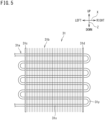
- FIG. 5 is a schematic view of a first heat exchanger in a refrigeration apparatus.
- the first heat exchanger 31 constituting the refrigeration apparatus 10 according to the present disclosure is a so-called fin-and-tube heat exchanger of a cross-fin type.
- the first heat exchanger 31 includes the heat transfer tube 31a, a plurality of fins 31b, and a pair of tube plates 31c and 31d.
- the first heat exchanger 31 causes heat exchange between the first refrigerant R1 in the first refrigerant circuit RC1 and air passing through the first heat exchanger 31.
- the heat transfer tube 31a is a metal circular tube.
- the metal constituting the heat transfer tube 31a can include copper, a copper alloy, stainless steel, aluminum, and an aluminum alloy.
- the heat transfer tube 31a will also be referred to as a circular tube 31a.
- the plurality of fins 31b is thin plates made of a metal, has an oblong shape in a side view, and is aligned parallel to each other at predetermined intervals in a width direction (the first direction X).
- Examples of the metal constituting the fins 31b can include aluminum and an aluminum alloy.
- the circular tube (heat transfer tube) 31a includes a plurality of linear tube portions 31x having a linear shape and a plurality of curved tube portions 31y having a U shape.
- the linear tube portions 31x penetrate a large number of fins 31b in a direction (the first direction X) in which the fins 31b are aligned.
- the curved tube portions 31y are disposed at an end portion in a width direction (the first direction X) of the first heat exchanger 31, and each connect the two linear tube portions 31x adjacent to each other.
- the heat transfer tubes 32a are constituted by multi-hole tubes each provided therein with a plurality of refrigerant flow paths 35.
- the heat transfer tubes 32a each have a section in a flat shape having a short direction and a longitudinal direction.
- the heat transfer tubes 32a have the longitudinal direction in which the plurality of refrigerant flow paths 35 is aligned.
- the plurality of refrigerant flow paths 35 is aligned in the air flow direction F.
- the plurality of refrigerant flow paths 35 is aligned in the second direction Y and extends in the first direction X.
- the heat transfer tubes 32a will also be referred to as flat multi-hole tubes 32a.
- the second heat exchanger 32 includes the plurality of heat transfer tubes 32a aligned in the third direction Z.
- the headers 32c and 32d are disposed to have longitudinal directions aligned to the third direction Z.
- Each of the heat transfer tubes 32a has a first end connected to the header 32c, and a second end connected to the header 32d.
- the fin 32b is disposed meanderingly between the heat transfer tubes 32a and 32a disposed vertically adjacent to each other.
- the second heat exchanger 32 is not limited to the above in terms of its posture, and may be provided in a posture having the third direction Z aligned to the lateral direction.
- the fin 32b is substantially equal in length in the second direction Y to the flat multi-hole tubes 32a. Accordingly in the second heat exchanger 32, the flat multi-hole tubes 32a and the fin 32b are flush with each other in respective end surfaces in the second direction Y.
- a heat transfer tube constituted by a flat multi-hole tube (the flat multi-hole tube 32a) is more likely to be damaged upon application of external force in comparison to a heat transfer tube constituted by a circular tube (the circular tube 31a).
- Application of external force to the flat multi-hole tube 32a is thus more likely to cause serious damage in comparison to application of external force to the circular tube 31a.
- the second heat exchanger 32 including the flat multi-hole tube 32a is more prioritized for protection and is preferably disposed at a location less likely to receive external force in comparison to the first heat exchanger 31 including the circular tube 31a.
- the second heat exchanger 32 is a so-called parallel flow heat exchanger in microchannel heat exchangers.
- the heat transfer tubes constituting the second heat exchanger 32 are the flat multi-hole tubes 32a, and the fin 32b is disposed meanderingly between the flat multi-hole tubes adjacent to each other.
- the fin 32b is a so-called corrugate fin.
- the parallel flow heat exchanger is typically smaller in volume (internal holding liquid quantity) in the heat exchanger than the cross-fin heat exchanger.
- the refrigeration apparatus 10 adopting the parallel flow heat exchanger as the second heat exchanger 32 can therefore reduce used quantity of the second refrigerant R2 in comparison to the refrigeration apparatus adopting the cross-fin heat exchanger.
- the third heat exchanger 33 constituting the refrigeration apparatus 10 according to the present disclosure is a plate heat exchanger. As depicted in FIG. 1 , the third heat exchanger 33 includes a first flow path 33a and a second flow path 33b provided between stacked plates. In the third heat exchanger 33, the first flow path 33a is connected to the first refrigerant circuit RC1, and the first refrigerant R1 flows to the first flow path 33a. In the third heat exchanger 33, the second flow path 33b is connected to the second refrigerant circuit RC2, and the second refrigerant R2 flows to the second flow path 33b.
- the third heat exchanger 33 causes heat exchange between the first refrigerant R1 flowing in the first flow path 33a and the second refrigerant R2 flowing in the second flow path 33b.
- the refrigeration apparatus 10 causes heat exchange between the first refrigerant R1 and the second refrigerant R2 with use of the third heat exchanger 33 to assist cooling capability of the first refrigerant circuit RC1 with cooling capability of the second refrigerant circuit RC2.
- the refrigeration apparatus 10 is preferred to use natural refrigerants as the first refrigerant R1 and the second refrigerant R2.
- a natural refrigerant includes a substance originally existing in nature, and examples thereof include ammonia (NH3), carbon dioxide (CO2), water (H2O), and hydrocarbon (HC).
- the refrigeration apparatus 10 according to the present embodiment uses carbon dioxide (CO2: R744) as the first refrigerant R1, and propane (C3H8: R290) as the second refrigerant R2.
- Carbon dioxide (CO2) has a global warming potential (GWP) of "1”
- propane (C3H8) has a global warming potential (GWP) of "3".
- the first refrigerant R1 used in the refrigeration apparatus according to the present disclosure is not limited to carbon dioxide (CO2)
- the second refrigerant R2 used in the refrigeration apparatus according to the present disclosure is not limited to propane (C3H8).
- the first refrigerant R1 and the second refrigerant R2 used in the refrigeration apparatus according to the present disclosure may be R32, R1234yf, R474a, R600a (isobutane), R454B, R454C, or the like.
- the second heat exchanger 32 in the refrigeration apparatus 10 is disposed leeward of the first heat exchanger 31 in the air flow direction F of the air flow generated by the fan 15.
- the first heat exchanger 31 is disposed outside the second heat exchanger 32. If some external force is applied to the heat source-side unit 11 thus configured during conveyance or the like, the external force is mainly applied not to the second heat exchanger 32 but to the first heat exchanger 31 disposed outside. When external force is applied to the heat source-side unit 11 including the first heat exchanger 31 and the second heat exchanger 32, the external force is less likely to be applied directly to the second heat exchanger 32. The refrigeration apparatus 10 can thus reduce risk of damage to the second heat exchanger 32.
- FIG. 8A is an explanatory view in an air flow direction, depicting a disposition relationship between a first heat exchanger and a second heat exchanger according to the first embodiment.
- the first heat exchanger 31 may include a first region A1 overlapped with the second heat exchanger 32 when viewed in the air flow direction F, and a second region A2 not overlapped with the second heat exchanger 32 when viewed in the air flow direction F.
- a region indicating the first heat exchanger 31 corresponds to a region between the pair of tube plates 31c and 31d (see FIG. 5 )
- a region indicating the second heat exchanger 32 corresponds to a region between the pair of headers 32c and 32d (see FIG. 6 ).
- the second heat exchanger 32 is disposed leeward of the first heat exchanger 31 in the air flow direction F, and the second heat exchanger 32 can thus be supported by a support 70 (see FIG. 2 and FIG. 3 ) for the fan 15.
- the second heat exchanger 32 has a lower portion supported by a first stay 71 provided at a lower portion of the support 70.
- the second heat exchanger 32 has an upper portion that may be further supported by a second stay 72 provided at a vertically intermediate portion of the support 70.
- the second heat exchanger 32 can be supported by the support 70 without separate provision of any support for the second heat exchanger 32 in the refrigeration apparatus 10 according to the present embodiment.
- FIG. 8B is an explanatory view in an air flow direction, depicting a disposition relationship between a first heat exchanger and a second heat exchanger according to the second embodiment.
- an area Sa4 of a fourth region A4 zoned by the outer shape of the second heat exchanger 32 may be smaller than an area Sa3 of a third region A3 zoned by the outer shape of the first heat exchanger 31 (Sa3 > Sa4), and the third region A3 may include the fourth region A4.
- the first heat exchanger 31 dimensionally larger in outer shape can be easily supported by the case 60 accommodating the first heat exchanger 31.
- the second heat exchanger 32 dimensionally smaller in outer shape is difficult to be supported by the case 60, and a support for the second heat exchanger 32 needs to be prepared separately from the support for the first heat exchanger 31.
- the second heat exchanger 32 is disposed leeward of the first heat exchanger 31 in the air flow direction F, and the second heat exchanger 32 can thus be supported by a support 70 (see FIG. 2 and FIG. 3 ) for the fan 15. Accordingly, even if the second heat exchanger 32 is dimensionally smaller in outer shape than the first heat exchanger 31 and the second heat exchanger 32 is accommodated in the outer shape of the first heat exchanger 31 when viewed in the air flow direction F, the second heat exchanger 32 can be supported by the support 70 without separate provision of any support for the second heat exchanger 32 in the refrigeration apparatus 10 according to the present embodiment.
- the refrigeration apparatus 10 includes the first heat exchanger 31 having the circular tube 31a as a heat transfer tube, and the second heat exchanger 32 including the flat multi-hole tube 32a as a heat transfer tube.
- the flat multi-hole tube 32a is weaker against external force than the circular tube 31a.
- the first heat exchanger 31 is disposed windward of the second heat exchanger 32 in the air flow direction F, to dispose the first heat exchanger 31 outside the second heat exchanger 32 in the heat source-side unit 11.
- the first heat exchanger 31 including the circular tube 31a is disposed windward of the second heat exchanger 32 including the flat multi-hole tube 32a in the air flow direction F, so as to reduce risk of damage to the second heat exchanger 32 including the flat multi-hole tube 32a weak against external force when the external force is applied to the heat source-side unit 11 including the first heat exchanger 31 and the second heat exchanger 32.
- the second heat exchanger 32 is constituted by a heat exchanger (the so-called parallel flow heat exchanger) including the plurality of flat multi-hole tubes 32a and the fin 32b meanderingly disposed between the flat multi-hole tubes 32a and 32a adjacent to each other.
- a heat exchanger the so-called parallel flow heat exchanger
- the flat multi-hole tubes 32a and the fin 32b are flush with each other and the flat multi-hole tubes 32a are thus not protected by the fin 32b. Accordingly, external force is likely to be applied directly to the flat multi-hole tubes 32a to damage the flat multi-hole tubes 32a in the second heat exchanger 32 configured as described above.
- the refrigeration apparatus 10 according to the above embodiment can reduce risk of damage to the flat multi-hole tubes 32a when the second heat exchanger 32 is constituted by the parallel flow heat exchanger.
- the refrigeration apparatus 10 according to the above embodiment can reduce used quantity of the second refrigerant R2 when the second heat exchanger 32 is constituted by the parallel flow heat exchanger.
- the fan 15 is disposed leeward of the second heat exchanger 32 in the air flow direction F, and the second heat exchanger 32 is fixed to the support 70 supporting the fan 15.
- the refrigeration apparatus 10 can fix the second heat exchanger 32 with use of the support 70 configured to fix the fan 15.
- the first heat exchanger 31 includes the first region A1 overlapped with the second heat exchanger 32 and the second region A2 not overlapped with the second heat exchanger 32 when viewed in the air flow direction F (see FIG. 8A ).
- the two heat exchangers 31 and 32 can be easily supported by a common support.
- the outer shapes of the two heat exchangers 31 and 32 are dimensionally different from each other and misaligned when viewed in the air flow direction F as depicted in FIG. 8A , the two heat exchangers 31 and 32 are difficult to be supported by a common support.
- the refrigeration apparatus 10 can fix the second heat exchanger 32 with use of the support 70 configured to fix the fan 15.
- the area Sa4 of the fourth region A4 zoned by the outer shape of the second heat exchanger 32 is smaller than the area Sa3 of the third region A3 zoned by the outer shape of the first heat exchanger 31, and the third region A3 includes the fourth region A4 (see FIG. 8B ).
- the two heat exchangers 31 and 32 can be easily supported by a common support.
- the outer shapes of the two heat exchangers 31 and 32 are dimensionally different from each other as depicted in FIG. 8B , the first heat exchanger 31 dimensionally larger can be easily supported by the case 60 accommodating the first heat exchanger 31, but the second heat exchanger 32 dimensionally smaller is difficult to be supported by the case 60.
- the second heat exchanger 32 can be fixed by the support 70 configured to fix the fan 15.
Landscapes
- Engineering & Computer Science (AREA)
- Physics & Mathematics (AREA)
- Thermal Sciences (AREA)
- Mechanical Engineering (AREA)
- General Engineering & Computer Science (AREA)
- Chemical & Material Sciences (AREA)
- Combustion & Propulsion (AREA)
- Geometry (AREA)
- Other Air-Conditioning Systems (AREA)
- Heat-Exchange Devices With Radiators And Conduit Assemblies (AREA)
- Air Filters, Heat-Exchange Apparatuses, And Housings Of Air-Conditioning Units (AREA)
Abstract
Description
- The present disclosure relates to a refrigeration apparatus.
- There is disclosed a refrigeration apparatus including a unit having a first refrigerant circuit configured to exhibit main cooling capability, a second refrigerant circuit configured to assist the first refrigerant circuit in the cooling capability, and a heat exchanger configured to cause heat exchange between a first refrigerant in the first refrigerant circuit and a second refrigerant in the second refrigerant circuit (see PATENT LITERATURE 1). The first refrigerant and the second refrigerant are different from each other in terms of refrigerant types in the refrigeration apparatus.
- PATENT LITERATURE 1:
WO 2014/181399 A - In the unit of the refrigeration apparatus, a first air heat exchanger included in the first refrigerant circuit and a second air heat exchanger included in the second refrigerant circuit may be aligned windward and leeward in an air flow direction of air subject to heat exchange. When the second air heat exchanger is disposed windward of the first air heat exchanger, the second air heat exchanger is disposed at an outermost location in the unit. In the unit thus configured, external force or the like is likely to be applied to the second air heat exchanger during conveyance, and the second air heat exchanger is thus likely to be damaged.
- It is an object of the present disclosure to provide a refrigeration apparatus including a unit having first and second air heat exchangers, and reduce risk of damage to the second air heat exchanger.
-
- (1) A refrigeration apparatus according to the present disclosure includes: a first refrigerant circuit including a first compressor, a first heat exchanger, a first expansion valve, and a utilization-side heat exchanger, and using a first refrigerant; a second refrigerant circuit including a second compressor, a second heat exchanger, and a second expansion valve, and using a second refrigerant; a third heat exchanger configured to cause heat exchange between the first refrigerant and the second refrigerant; and a fan, in which the first heat exchanger includes a heat transfer tube being a circular tube, the second heat exchanger includes a heat transfer tube being a flat multi-hole tube, and the second heat exchanger is disposed leeward of the first heat exchanger in an air flow direction of an air flow generated by the fan.
- The refrigeration apparatus according to the present disclosure includes the first heat exchanger adopting the circular tube as a heat transfer tube, and the second heat exchanger adopting the flat multi-hole tube as a heat transfer tube. The flat multi-hole tube is weaker against external force than the circular tube. In the refrigeration apparatus according to the present disclosure, the first heat exchanger is disposed windward of the second heat exchanger in the air flow direction, to dispose the first heat exchanger outside the second heat exchanger. In the refrigeration apparatus according to the present disclosure, the first heat exchanger including the circular tube as a heat transfer tube is disposed windward of the second heat exchanger including the flat multi-hole tube as a heat transfer tube in the air flow direction, so as to reduce risk of damage to the second heat exchanger when external force is applied to a unit including the first heat exchanger and the second heat exchanger.
- (2) In the refrigeration apparatus according to (1) described above of the present disclosure, preferably, the second heat exchanger is constituted by a heat exchanger including a plurality of the flat multi-hole tubes, and a fin meanderingly disposed between the flat multi-hole tubes adjacent to each other.
- In the heat exchanger thus configured, the flat multi-hole tubes and the fin are flush with each other and the flat multi-hole tubes are thus not protected by the fin. Accordingly, the flat multi-hole tubes are likely to directly receive external force to be damaged in the heat exchanger configured as described above. The refrigeration apparatus according to the present disclosure can reduce risk of damage to the flat multi-hole tubes when the heat exchanger configured as described above is adopted as the second heat exchanger. The refrigeration apparatus according to the present disclosure adopts the heat exchanger configured as described above to reduce used quantity of the second refrigerant.
- (3) In the refrigeration apparatus according to (1) or (2) described above of the present disclosure, preferably, the fan is disposed leeward of the second heat exchanger in the air flow direction, and the second heat exchanger is fixed to a support configured to support the fan.
- In the refrigeration apparatus thus configured, the fan is disposed leeward of the second heat exchanger in the air flow direction. The refrigeration apparatus according to the present disclosure can accordingly fix the second heat exchanger with use of the support configured to fix the fan.
- (4) In the refrigeration apparatus according to any one of (1) to (3) described above of the present disclosure, preferably, the first heat exchanger includes a first region overlapped with the second heat exchanger when viewed in the air flow direction, and a second region not overlapped with the second heat exchanger when viewed in the air flow direction.
- In the refrigeration apparatus including the first heat exchanger and the second heat exchanger, in a case where outer shapes of the heat exchangers are dimensionally equal and positionally identical when viewed in the air flow direction, the two heat exchangers can be easily supported by a common support. In another case where the outer shapes of the two heat exchangers are dimensionally different from each other and misaligned when viewed in the air flow direction, the two heat exchangers are difficult to be supported by a common support. Even if the first heat exchanger includes the first region overlapped with the second heat exchanger and the second region not overlapped with the second heat exchanger when viewed in the air flow direction, the refrigeration apparatus according to the present disclosure can fix the second heat exchanger with use of the support configured to fix the fan.
- (5) In the refrigeration apparatus according to any one of (1) to (3) described above of the present disclosure, preferably, when the first heat exchanger and the second heat exchanger are viewed in the air flow direction, an area of a fourth region zoned by an outer shape of the second heat exchanger is smaller than an area of a third region zoned by an outer shape of the first heat exchanger, and the third region includes the fourth region.
- In the refrigeration apparatus including the first heat exchanger and the second heat exchanger, in a case where the outer shapes of the two heat exchangers are dimensionally equal to each other, the two heat exchangers can be easily supported by a common support. In another case where the outer shapes of the two heat exchangers are dimensionally different from each other, the heat exchanger dimensionally larger can be easily supported by a frame of a case accommodating this heat exchanger, but the heat exchanger dimensionally smaller is difficult to be supported by the frame of the case. In the refrigeration apparatus according to the present disclosure, even if the second heat exchanger is dimensionally smaller in outer shape than the first heat exchanger when viewed in the air flow direction and the outer shape of the first heat exchanger accommodates the second heat exchanger, the second heat exchanger can be fixed by the support configured to fix the fan.
-
-
FIG. 1 is an explanatory view of refrigerant circuits in a refrigeration apparatus according to an embodiment of the present disclosure. -
FIG. 2 is an explanatory sectional plan view of a heat source-side unit in the refrigeration apparatus. -
FIG. 3 is an explanatory sectional side view of the heat source-side unit in the refrigeration apparatus. -
FIG. 4 is an explanatory sectional side view depicting a state where a second heat exchanger is supported in another embodiment. -
FIG. 5 is a schematic view of a first heat exchanger in the refrigeration apparatus. -
FIG. 6 is a schematic view of the second heat exchanger in the refrigeration apparatus. -
FIG. 7 is a partial schematic sectional view depicting heat transfer tubes and fins constituting the second heat exchanger. -
FIG. 8A is an explanatory view in an air flow direction, depicting a disposition relationship between a first heat exchanger and a second heat exchanger according to a first embodiment. -
FIG. 8B is an explanatory view in an air flow direction, depicting a disposition relationship between a first heat exchanger and a second heat exchanger according to a second embodiment. - A refrigeration apparatus according to each of embodiments of the present disclosure will be described in detail hereinafter with reference to the accompanying drawings.
FIG. 1 is an explanatory view of refrigerant circuits in a refrigeration apparatus according to an embodiment of the present disclosure. As depicted inFIG. 1 , the present disclosure provides arefrigeration apparatus 10 including a heat source-side unit 11, a utilization-side unit 12, arefrigerant pipe 13 connecting the heat source-side unit 11 and the utilization-side unit 12, and afan 15. Therefrigeration apparatus 10 exemplified in the present embodiment is an air conditioner configured to condition air in a target space with use of the utilization-side unit 12. Therefrigeration apparatus 10 is an air conditioner of a separate type separately including the heat source-side unit (outdoor unit) 11 and the utilization-side unit (indoor unit) 12. The present embodiment exemplifies the air conditioner as therefrigeration apparatus 10, although the refrigeration apparatus according to the present disclosure may be a refrigerated case or the like, without being limited to the air conditioner. Therefrigerant pipe 13 includes agate valve 18 disposed at each of portions entering and exiting a case of the heat source-side unit 11. - The heat source-
side unit 11 includes afirst compressor 21, asecond compressor 22, afirst heat exchanger 31, asecond heat exchanger 32, athird heat exchanger 33, afirst expansion valve 41, asecond expansion valve 42, a four-way switching valve 50, afirst accumulator 51, and asecond accumulator 52. The utilization-side unit 12 includes a utilization-side heat exchanger 34. - The
refrigeration apparatus 10 includes a first refrigerant circuit RC1 including thefirst compressor 21, thefirst heat exchanger 31, thefirst expansion valve 41, the utilization-side heat exchanger 34, and therefrigerant pipe 13 connecting these devices, and a second refrigerant circuit RC2 including thesecond compressor 22, thesecond heat exchanger 32, thesecond expansion valve 42, and arefrigerant pipe 14 connecting these devices. The first refrigerant circuit RC1 uses a first refrigerant R1 as a refrigerant and is configured to execute refrigeration cycle operation. The second refrigerant circuit RC2 uses a second refrigerant R2 as a refrigerant different from the first refrigerant R1 and is configured to execute refrigeration cycle operation. - Each of the
first compressor 21 and thesecond compressor 22 sucks a low-pressure gas refrigerant and discharges a high-pressure gas refrigerant. Each of thefirst compressor 21 and thesecond compressor 22 includes a motor (not depicted) having a number of operating revolutions adjustable through inverter control. Each of thefirst compressor 21 and thesecond compressor 22 is of a variable capacity type (capability variable type) having capacity (capability) variable through inverter control of the motor. Each of thefirst compressor 21 and thesecond compressor 22 may alternatively be of a constant capacity type. - The four-
way switching valve 50 is configured to reverse a flow of the first refrigerant R1 in therefrigerant pipe 13 of the first refrigerant circuit RC1, and switchingly supply one of thefirst heat exchanger 31 and the utilization-side heat exchanger 34 with the first refrigerant R1 discharged from thefirst compressor 21. Therefrigeration apparatus 10 is configured to switch between cooling operation and heating operation by switching a flow direction of the first refrigerant R1 with use of the four-way switching valve 50. Therefrigeration apparatus 10 according to the present embodiment may alternatively include no four-way switching valve, and may be used exclusively for cooling. - The
first expansion valve 41 is constituted by a motor valve configured to adjust a flow rate of the first refrigerant R1. During cooling operation, a control device (not depicted) included in therefrigeration apparatus 10 adjusts an opening degree of thefirst expansion valve 41 to adjust cooling capability exhibited by the first refrigerant circuit RC1. During heating operation, the control device (not depicted) in therefrigeration apparatus 10 maximizes the opening degree of thefirst expansion valve 41. - The
second expansion valve 42 is constituted by a motor valve configured to adjust a flow rate of the second refrigerant R2. During cooling operation, the control device (not depicted) in therefrigeration apparatus 10 adjusts an opening degree of thesecond expansion valve 42 to adjust cooling capability exhibited by the second refrigerant circuit RC2. - The
refrigeration apparatus 10 causes heat exchange between the first refrigerant R1 and the second refrigerant R2 in thethird heat exchanger 33 to assist cooling capability of the first refrigerant circuit RC1 with cooling capability of the second refrigerant circuit RC2. During cooling operation, the control device (not depicted) in therefrigeration apparatus 10 adjusts the opening degree of thesecond expansion valve 42 to adjust heat exchange quantity between the first refrigerant R1 and the second refrigerant R2. -
FIG. 2 is an explanatory sectional plan view of the heat source-side unit in the refrigeration apparatus.FIG. 3 is an explanatory sectional side view of the heat source-side unit in the refrigeration apparatus. The following description includes expressions of up, down, front, rear, left, and right, which follow arrows indicated inFIG. 2 andFIG. 3 . Specifically,FIG. 2 ,FIG. 3 and the like include arrows X, Y, and Z perpendicular to one another. The arrow X indicates a direction (first direction) assumed as a lateral direction, the arrow Y indicates a direction (second direction) assumed as an anteroposterior direction, and the arrow Z indicates a direction (third direction) assumed as a vertical direction. In the following description, the lateral direction will also be referred to as a first direction X, the anteroposterior direction will also be referred to as a second direction Y, and the vertical direction will also be referred to as a third direction Z. These expressions are merely exemplary. Alternatively, the direction X may be assumed as the anteroposterior direction, and the direction Y may be assumed as the lateral direction. - As depicted in
FIG. 1 to FIG. 3 , the heat source-side unit 11 includes acase 60. As depicted inFIG. 2 andFIG. 3 , thecase 60 has a rectangular parallelepiped shape, and has a rectangular shape in a planar view. Thecase 60 has an interior provided with a sectioningwall 61 zoning a machine chamber S1 and a heat exchange chamber S2. Thecase 60 includes twoadjacent side walls air intake ports side wall 66 that is disposed adjacent to theside wall 63 having theair intake port 65 and is provided with an air blow-outport 67. - The machine chamber S1 accommodates the
first compressor 21, thesecond compressor 22, thethird heat exchanger 33, thefirst accumulator 51, and thesecond accumulator 52. The machine chamber S1 further accommodates, in addition to the above, the four-way switching valve 50 (not depicted), the first expansion valve 41 (not depicted), the second expansion valve 42 (not depicted), an oil separator, and the like. The machine chamber S1 is provided with a control board (not depicted) configured to control devices constituting therefrigeration apparatus 10. - The heat exchange chamber S2 accommodates the
first heat exchanger 31, thesecond heat exchanger 32, thefan 15, and afan motor 16. Thefan 15 is connected to a shaft of thefan motor 16, and is rotationally driven by thefan motor 16. - The
first heat exchanger 31 includes a heat transfer tube (aheat transfer tube 31a to be described later) in which the first refrigerant R1 circulating in the first refrigerant circuit RC1 flows. Thefirst heat exchanger 31 is connected to thefirst compressor 21 in the machine chamber S1 via the refrigerant pipe 13 (seeFIG. 1 ). Thesecond heat exchanger 32 includes a heat transfer tube (aheat transfer tube 32a to be described later) in which the second refrigerant R2 circulating in the second refrigerant circuit RC2 flows. Thesecond heat exchanger 32 is connected to thesecond compressor 22 in the machine chamber S1 via the refrigerant pipe 14 (seeFIG. 1 ). - The
fan 15 is disposed in a posture to cause a positive pressure surface to face theside wall 66 provided with the air blow-outport 67 and cause a negative pressure surface to face theside wall 62 provided with theair intake port 64. When thefan motor 16 is actuated, thefan 15 rotates to import air to the heat exchange chamber S2 via theair intake ports first heat exchanger 31 to exchange heat with the first refrigerant R1, then further passes through thesecond heat exchanger 32 to exchange heat with the second refrigerant R2, and is subsequently exhausted via the air blow-outport 67. Thefan 15 generates an air flow passing through thefirst heat exchanger 31 and thesecond heat exchanger 32. The refrigerants passing through thefirst heat exchanger 31 and thesecond heat exchanger 32 exchange heat with the air passing through thefirst heat exchanger 31 and thesecond heat exchanger 32. As depicted inFIG. 1 to FIG. 3 , the air flow generated by thefan 15 has a direction indicated by arrow F. In the following description, the direction of the air flow will be referred to as an air flow direction F. - The
first heat exchanger 31 according to the present embodiment has an L shape in a planar view. Thefirst heat exchanger 31 is bent near acorner 68 between the twoside walls air intake ports side walls first heat exchanger 31 included in therefrigeration apparatus 10 according to the present disclosure is not limited to the above, and may alternatively have a rectangular shape or the like in a planar view. - The
second heat exchanger 32 according to the present embodiment has a rectangular shape in a planar view. Thesecond heat exchanger 32 extends along a portion of thefirst heat exchanger 31 along theside wall 62 and is disposed leeward of thefirst heat exchanger 31 in the air flow direction F. Thesecond heat exchanger 32 included in therefrigeration apparatus 10 according to the present disclosure is not limited to the above in terms of its shape. -
FIG. 5 is a schematic view of a first heat exchanger in a refrigeration apparatus. As depicted inFIG. 5 , thefirst heat exchanger 31 constituting therefrigeration apparatus 10 according to the present disclosure is a so-called fin-and-tube heat exchanger of a cross-fin type. Thefirst heat exchanger 31 includes theheat transfer tube 31a, a plurality offins 31b, and a pair oftube plates first heat exchanger 31 causes heat exchange between the first refrigerant R1 in the first refrigerant circuit RC1 and air passing through thefirst heat exchanger 31. - The
heat transfer tube 31a is a metal circular tube. Examples of the metal constituting theheat transfer tube 31a can include copper, a copper alloy, stainless steel, aluminum, and an aluminum alloy. Hereinafter, theheat transfer tube 31a will also be referred to as acircular tube 31a. The plurality offins 31b is thin plates made of a metal, has an oblong shape in a side view, and is aligned parallel to each other at predetermined intervals in a width direction (the first direction X). Examples of the metal constituting thefins 31b can include aluminum and an aluminum alloy. - The circular tube (heat transfer tube) 31a includes a plurality of
linear tube portions 31x having a linear shape and a plurality ofcurved tube portions 31y having a U shape. Thelinear tube portions 31x penetrate a large number offins 31b in a direction (the first direction X) in which thefins 31b are aligned. Thecurved tube portions 31y are disposed at an end portion in a width direction (the first direction X) of thefirst heat exchanger 31, and each connect the twolinear tube portions 31x adjacent to each other. - The
tube plates first heat exchanger 31. Thetube plates linear tube portions 31x in thecircular tube 31a to support thecircular tube 31a. As depicted inFIG. 5 , thetube plates fins 31b. -
FIG. 6 is a schematic view of a second heat exchanger in a refrigeration apparatus.FIG. 7 is a partial schematic sectional view depicting heat transfer tubes and fins constituting the second heat exchanger. Thesecond heat exchanger 32 constituting therefrigeration apparatus 10 according to the present disclosure is a microchannel heat exchanger. As depicted inFIG. 6 andFIG. 7 , thesecond heat exchanger 32 includes a plurality ofheat transfer tubes 32a, afin 32b, and a pair ofheaders heat transfer tubes 32a, thefin 32b, and theheaders second heat exchanger 32 causes heat exchange between the second refrigerant R2 in the second refrigerant circuit RC2 and air passing through thesecond heat exchanger 32. - As depicted in
FIG. 7 , theheat transfer tubes 32a are constituted by multi-hole tubes each provided therein with a plurality ofrefrigerant flow paths 35. Theheat transfer tubes 32a each have a section in a flat shape having a short direction and a longitudinal direction. Theheat transfer tubes 32a have the longitudinal direction in which the plurality ofrefrigerant flow paths 35 is aligned. The plurality ofrefrigerant flow paths 35 is aligned in the air flow direction F. As depicted inFIG, 6 andFIG. 7 , the plurality ofrefrigerant flow paths 35 is aligned in the second direction Y and extends in the first direction X. Hereinafter, theheat transfer tubes 32a will also be referred to as flatmulti-hole tubes 32a. - As depicted in
FIG. 6 andFIG. 7 , thesecond heat exchanger 32 includes the plurality ofheat transfer tubes 32a aligned in the third direction Z. Theheaders heat transfer tubes 32a has a first end connected to theheader 32c, and a second end connected to theheader 32d. Thefin 32b is disposed meanderingly between theheat transfer tubes refrigeration apparatus 10 according to the present embodiment, thesecond heat exchanger 32 is not limited to the above in terms of its posture, and may be provided in a posture having the third direction Z aligned to the lateral direction. - As depicted in
FIG. 7 , the flatmulti-hole tubes 32a each have end surfaces in the third direction Z, in other words, upper and lower surfaces that are even surfaces expanding in the first direction X and the second direction Y. Each of the flatmulti-hole tubes 32a has respective end surfaces in the first direction X each having a section as a curved surface curved into a semicircular shape. - The
fin 32b is substantially equal in length in the second direction Y to the flatmulti-hole tubes 32a. Accordingly in thesecond heat exchanger 32, the flatmulti-hole tubes 32a and thefin 32b are flush with each other in respective end surfaces in the second direction Y. - Typically, a heat transfer tube constituted by a flat multi-hole tube (the flat
multi-hole tube 32a) is more likely to be damaged upon application of external force in comparison to a heat transfer tube constituted by a circular tube (thecircular tube 31a). Application of external force to the flatmulti-hole tube 32a is thus more likely to cause serious damage in comparison to application of external force to thecircular tube 31a. Accordingly, thesecond heat exchanger 32 including the flatmulti-hole tube 32a is more prioritized for protection and is preferably disposed at a location less likely to receive external force in comparison to thefirst heat exchanger 31 including thecircular tube 31a. - The
second heat exchanger 32 according to the present embodiment is a so-called parallel flow heat exchanger in microchannel heat exchangers. The heat transfer tubes constituting thesecond heat exchanger 32 are the flatmulti-hole tubes 32a, and thefin 32b is disposed meanderingly between the flat multi-hole tubes adjacent to each other. Thefin 32b is a so-called corrugate fin. When a cross-fin heat exchanger and a parallel flow heat exchanger equal in heat exchange quantity are compared with each other, the parallel flow heat exchanger is typically smaller in volume (internal holding liquid quantity) in the heat exchanger than the cross-fin heat exchanger. Therefrigeration apparatus 10 adopting the parallel flow heat exchanger as thesecond heat exchanger 32 can therefore reduce used quantity of the second refrigerant R2 in comparison to the refrigeration apparatus adopting the cross-fin heat exchanger. - The
third heat exchanger 33 constituting therefrigeration apparatus 10 according to the present disclosure is a plate heat exchanger. As depicted inFIG. 1 , thethird heat exchanger 33 includes a first flow path 33a and a second flow path 33b provided between stacked plates. In thethird heat exchanger 33, the first flow path 33a is connected to the first refrigerant circuit RC1, and the first refrigerant R1 flows to the first flow path 33a. In thethird heat exchanger 33, the second flow path 33b is connected to the second refrigerant circuit RC2, and the second refrigerant R2 flows to the second flow path 33b. Thethird heat exchanger 33 causes heat exchange between the first refrigerant R1 flowing in the first flow path 33a and the second refrigerant R2 flowing in the second flow path 33b. Therefrigeration apparatus 10 causes heat exchange between the first refrigerant R1 and the second refrigerant R2 with use of thethird heat exchanger 33 to assist cooling capability of the first refrigerant circuit RC1 with cooling capability of the second refrigerant circuit RC2. - The
refrigeration apparatus 10 according to the present disclosure is preferred to use natural refrigerants as the first refrigerant R1 and the second refrigerant R2. A natural refrigerant includes a substance originally existing in nature, and examples thereof include ammonia (NH3), carbon dioxide (CO2), water (H2O), and hydrocarbon (HC). Therefrigeration apparatus 10 according to the present embodiment uses carbon dioxide (CO2: R744) as the first refrigerant R1, and propane (C3H8: R290) as the second refrigerant R2. Carbon dioxide (CO2) has a global warming potential (GWP) of "1", and propane (C3H8) has a global warming potential (GWP) of "3". The first refrigerant R1 used in the refrigeration apparatus according to the present disclosure is not limited to carbon dioxide (CO2), and the second refrigerant R2 used in the refrigeration apparatus according to the present disclosure is not limited to propane (C3H8). The first refrigerant R1 and the second refrigerant R2 used in the refrigeration apparatus according to the present disclosure may be R32, R1234yf, R474a, R600a (isobutane), R454B, R454C, or the like. - As depicted in
FIG. 1 to FIG. 3 , thesecond heat exchanger 32 in therefrigeration apparatus 10 is disposed leeward of thefirst heat exchanger 31 in the air flow direction F of the air flow generated by thefan 15. - When the
second heat exchanger 32 is disposed leeward of thefirst heat exchanger 31 in the air flow direction F in the heat source-side unit 11, thefirst heat exchanger 31 is disposed outside thesecond heat exchanger 32. If some external force is applied to the heat source-side unit 11 thus configured during conveyance or the like, the external force is mainly applied not to thesecond heat exchanger 32 but to thefirst heat exchanger 31 disposed outside. When external force is applied to the heat source-side unit 11 including thefirst heat exchanger 31 and thesecond heat exchanger 32, the external force is less likely to be applied directly to thesecond heat exchanger 32. Therefrigeration apparatus 10 can thus reduce risk of damage to thesecond heat exchanger 32. -
FIG. 8A is an explanatory view in an air flow direction, depicting a disposition relationship between a first heat exchanger and a second heat exchanger according to the first embodiment. In therefrigeration apparatus 10 according to the first embodiment, thefirst heat exchanger 31 may include a first region A1 overlapped with thesecond heat exchanger 32 when viewed in the air flow direction F, and a second region A2 not overlapped with thesecond heat exchanger 32 when viewed in the air flow direction F. In this description, a region indicating thefirst heat exchanger 31 corresponds to a region between the pair oftube plates FIG. 5 ), and a region indicating thesecond heat exchanger 32 corresponds to a region between the pair ofheaders FIG. 6 ). - In a case where outer shapes of the two
heat exchangers FIG. 8A , the twoheat exchangers second heat exchanger 32 needs to be prepared separately from a support for thefirst heat exchanger 31. - In the
refrigeration apparatus 10 according to the present embodiment, thesecond heat exchanger 32 is disposed leeward of thefirst heat exchanger 31 in the air flow direction F, and thesecond heat exchanger 32 can thus be supported by a support 70 (seeFIG. 2 andFIG. 3 ) for thefan 15. Specifically, as depicted inFIG. 3 , thesecond heat exchanger 32 has a lower portion supported by afirst stay 71 provided at a lower portion of thesupport 70. Alternatively as depicted inFIG. 4 , thesecond heat exchanger 32 has an upper portion that may be further supported by asecond stay 72 provided at a vertically intermediate portion of thesupport 70. Accordingly, even if thefirst heat exchanger 31 includes the first region A1 overlapped with thesecond heat exchanger 32 and the second region A2 not overlapped with thesecond heat exchanger 32 when viewed in the air flow direction F, thesecond heat exchanger 32 can be supported by thesupport 70 without separate provision of any support for thesecond heat exchanger 32 in therefrigeration apparatus 10 according to the present embodiment. -
FIG. 8B is an explanatory view in an air flow direction, depicting a disposition relationship between a first heat exchanger and a second heat exchanger according to the second embodiment. In therefrigeration apparatus 10 according to the second embodiment, when thefirst heat exchanger 31 and thesecond heat exchanger 32 are viewed in the air flow direction F, an area Sa4 of a fourth region A4 zoned by the outer shape of thesecond heat exchanger 32 may be smaller than an area Sa3 of a third region A3 zoned by the outer shape of the first heat exchanger 31 (Sa3 > Sa4), and the third region A3 may include the fourth region A4. - When the outer shapes of the two
heat exchangers FIG. 8B , thefirst heat exchanger 31 dimensionally larger in outer shape can be easily supported by thecase 60 accommodating thefirst heat exchanger 31. Meanwhile, thesecond heat exchanger 32 dimensionally smaller in outer shape is difficult to be supported by thecase 60, and a support for thesecond heat exchanger 32 needs to be prepared separately from the support for thefirst heat exchanger 31. - In the
refrigeration apparatus 10 according to the present embodiment, thesecond heat exchanger 32 is disposed leeward of thefirst heat exchanger 31 in the air flow direction F, and thesecond heat exchanger 32 can thus be supported by a support 70 (seeFIG. 2 andFIG. 3 ) for thefan 15. Accordingly, even if thesecond heat exchanger 32 is dimensionally smaller in outer shape than thefirst heat exchanger 31 and thesecond heat exchanger 32 is accommodated in the outer shape of thefirst heat exchanger 31 when viewed in the air flow direction F, thesecond heat exchanger 32 can be supported by thesupport 70 without separate provision of any support for thesecond heat exchanger 32 in therefrigeration apparatus 10 according to the present embodiment. -
- (1) The
refrigeration apparatus 10 according to the embodiment described above includes the first refrigerant circuit RC1 having thefirst compressor 21, thefirst heat exchanger 31, thefirst expansion valve 41, and the utilization-side heat exchanger 34, and using the first refrigerant R1, the second refrigerant circuit RC2 having thesecond compressor 22, thesecond heat exchanger 32, and thesecond expansion valve 42, and using the second refrigerant R2, thethird heat exchanger 33 configured to cause heat exchange between the first refrigerant R1 and the second refrigerant R2, and thefan 15. In therefrigeration apparatus 10, the heat transfer tube constituting thefirst heat exchanger 31 is thecircular tube 31a, and the heat transfer tube constituting thesecond heat exchanger 32 is the flatmulti-hole tube 32a. Thesecond heat exchanger 32 in therefrigeration apparatus 10 is disposed leeward of thefirst heat exchanger 31 in the air flow direction F of the air flow generated by thefan 15. - The
refrigeration apparatus 10 according to the above embodiment includes thefirst heat exchanger 31 having thecircular tube 31a as a heat transfer tube, and thesecond heat exchanger 32 including the flatmulti-hole tube 32a as a heat transfer tube. The flatmulti-hole tube 32a is weaker against external force than thecircular tube 31a. In therefrigeration apparatus 10 according to the above embodiment, thefirst heat exchanger 31 is disposed windward of thesecond heat exchanger 32 in the air flow direction F, to dispose thefirst heat exchanger 31 outside thesecond heat exchanger 32 in the heat source-side unit 11. In therefrigeration apparatus 10 according to the above embodiment, thefirst heat exchanger 31 including thecircular tube 31a is disposed windward of thesecond heat exchanger 32 including the flatmulti-hole tube 32a in the air flow direction F, so as to reduce risk of damage to thesecond heat exchanger 32 including the flatmulti-hole tube 32a weak against external force when the external force is applied to the heat source-side unit 11 including thefirst heat exchanger 31 and thesecond heat exchanger 32. - (2) In the
refrigeration apparatus 10 according to the above embodiment, thesecond heat exchanger 32 is constituted by a heat exchanger (the so-called parallel flow heat exchanger) including the plurality of flatmulti-hole tubes 32a and thefin 32b meanderingly disposed between the flatmulti-hole tubes - In the
second heat exchanger 32 according to the above embodiment, the flatmulti-hole tubes 32a and thefin 32b are flush with each other and the flatmulti-hole tubes 32a are thus not protected by thefin 32b. Accordingly, external force is likely to be applied directly to the flatmulti-hole tubes 32a to damage the flatmulti-hole tubes 32a in thesecond heat exchanger 32 configured as described above. Therefrigeration apparatus 10 according to the above embodiment can reduce risk of damage to the flatmulti-hole tubes 32a when thesecond heat exchanger 32 is constituted by the parallel flow heat exchanger. Therefrigeration apparatus 10 according to the above embodiment can reduce used quantity of the second refrigerant R2 when thesecond heat exchanger 32 is constituted by the parallel flow heat exchanger. - (3) In the
refrigeration apparatus 10 according to the above embodiment, thefan 15 is disposed leeward of thesecond heat exchanger 32 in the air flow direction F, and thesecond heat exchanger 32 is fixed to thesupport 70 supporting thefan 15. - In this manner, the
refrigeration apparatus 10 according to the above embodiment can fix thesecond heat exchanger 32 with use of thesupport 70 configured to fix thefan 15. - (4) In the
refrigeration apparatus 10 according to the above embodiment, thefirst heat exchanger 31 includes the first region A1 overlapped with thesecond heat exchanger 32 and the second region A2 not overlapped with thesecond heat exchanger 32 when viewed in the air flow direction F (seeFIG. 8A ). - In a case where there are provided the
first heat exchanger 31 and thesecond heat exchanger 32 and the outer shapes of theheat exchangers heat exchangers heat exchangers FIG. 8A , the twoheat exchangers first heat exchanger 31 includes the first region A1 overlapped with thesecond heat exchanger 32 and the second region A2 not overlapped with thesecond heat exchanger 32 when viewed in the air flow direction F, therefrigeration apparatus 10 according to the above embodiment can fix thesecond heat exchanger 32 with use of thesupport 70 configured to fix thefan 15. - (5) In the
refrigeration apparatus 10 according to the above embodiment, when thefirst heat exchanger 31 and thesecond heat exchanger 32 are viewed in the air flow direction F, the area Sa4 of the fourth region A4 zoned by the outer shape of thesecond heat exchanger 32 is smaller than the area Sa3 of the third region A3 zoned by the outer shape of thefirst heat exchanger 31, and the third region A3 includes the fourth region A4 (seeFIG. 8B ). - In a case where there are provided the
first heat exchanger 31 and thesecond heat exchanger 32 and the outer shapes of theheat exchangers heat exchangers heat exchangers FIG. 8B , thefirst heat exchanger 31 dimensionally larger can be easily supported by thecase 60 accommodating thefirst heat exchanger 31, but thesecond heat exchanger 32 dimensionally smaller is difficult to be supported by thecase 60. In therefrigeration apparatus 10 according to the above embodiment, even if thesecond heat exchanger 32 is dimensionally smaller in outer shape than thefirst heat exchanger 31 when viewed in the air flow direction F and the outer shape of thefirst heat exchanger 31 accommodates thesecond heat exchanger 32, thesecond heat exchanger 32 can be fixed by thesupport 70 configured to fix thefan 15. - While various embodiments have been described herein above, it is to be appreciated that various changes in form and detail may be made without departing from the spirit and scope presently or hereafter claimed.
-
- 10
- refrigeration apparatus
- 15
- fan
- 21
- first compressor
- 22
- second compressor
- 31
- first heat exchanger
- 31a
- circular tube
- 32
- second heat exchanger
- 32a
- flat multi-hole tube
- 32b
- fin
- 33
- third heat exchanger
- 34
- utilization-side heat exchanger
- 41
- first expansion valve
- 42
- second expansion valve
- 70
- support
- R1
- first refrigerant
- R2
- second refrigerant
- RC1
- first refrigerant circuit
- RC2
- second refrigerant circuit
- F
- air flow direction
Claims (5)
- A refrigeration apparatus (10) comprising:a first refrigerant circuit (RC1) including a first compressor (21), a first heat exchanger (31), a first expansion valve (41), and a utilization-side heat exchanger (34), and using a first refrigerant (R1);a second refrigerant circuit (RC2) including a second compressor (22), a second heat exchanger (32), and a second expansion valve (42), and using a second refrigerant (R2);a third heat exchanger (33) configured to cause heat exchange between the first refrigerant (R1) and the second refrigerant (R2); anda fan (15),wherein the first heat exchanger (31) includes a heat transfer tube being a circular tube (31a),the second heat exchanger (32) includes a heat transfer tube being a flat multi-hole tube (32a), andthe second heat exchanger (32) is disposed leeward of the first heat exchanger (31) in an air flow direction (F) of an air flow generated by the fan (15).
- The refrigeration apparatus (10) according to claim 1, wherein the second heat exchanger (32) is constituted by a heat exchanger including a plurality of the flat multi-hole tubes (32a), and a fin (32b) meanderingly disposed between the flat multi-hole tubes (32a) adjacent to each other.
- The refrigeration apparatus (10) according to claim 1 or 2, whereinthe fan (15) is disposed leeward of the second heat exchanger (32) in the air flow direction (F), andthe second heat exchanger (32) is fixed to a support (70) configured to support the fan (15).
- The refrigeration apparatus (10) according to claim 3, wherein the first heat exchanger (31) includes a first region (A1) overlapped with the second heat exchanger (32) when viewed in the air flow direction (F), and a second region (A2) not overlapped with the second heat exchanger (32) when viewed in the air flow direction (F).
- The refrigeration apparatus (10) according to claim 3, wherein, when the first heat exchanger (31) and the second heat exchanger (32) are viewed in the air flow direction (F), an area (Sa4) of a fourth region (A4) zoned by an outer shape of the second heat exchanger (32) is smaller than an area (Sa3) of a third region (A3) zoned by an outer shape of the first heat exchanger (31), and the third region (A3) includes the fourth region (A4).
Applications Claiming Priority (2)
| Application Number | Priority Date | Filing Date | Title |
|---|---|---|---|
| JP2023109478 | 2023-07-03 | ||
| PCT/JP2024/021170 WO2025009339A1 (en) | 2023-07-03 | 2024-06-11 | Refrigeration device |
Publications (2)
| Publication Number | Publication Date |
|---|---|
| EP4513109A1 true EP4513109A1 (en) | 2025-02-26 |
| EP4513109A4 EP4513109A4 (en) | 2025-05-28 |
Family
ID=93258938
Family Applications (2)
| Application Number | Title | Priority Date | Filing Date |
|---|---|---|---|
| EP24789705.1A Pending EP4513109A4 (en) | 2023-07-03 | 2024-06-11 | REFRIGERATION DEVICE |
| EP24786340.0A Pending EP4513108A4 (en) | 2023-07-03 | 2024-07-03 | HEAT SOURCE UNIT AND REFRIGERATION DEVICE |
Family Applications After (1)
| Application Number | Title | Priority Date | Filing Date |
|---|---|---|---|
| EP24786340.0A Pending EP4513108A4 (en) | 2023-07-03 | 2024-07-03 | HEAT SOURCE UNIT AND REFRIGERATION DEVICE |
Country Status (5)
| Country | Link |
|---|---|
| US (2) | US20260118040A1 (en) |
| EP (2) | EP4513109A4 (en) |
| JP (2) | JP7656242B2 (en) |
| CN (2) | CN121420166A (en) |
| WO (2) | WO2025009339A1 (en) |
Family Cites Families (23)
| Publication number | Priority date | Publication date | Assignee | Title |
|---|---|---|---|---|
| JPH08247683A (en) * | 1995-03-10 | 1996-09-27 | Toshiba Ave Corp | Heat exchanger |
| JP3540530B2 (en) * | 1996-12-13 | 2004-07-07 | 東芝キヤリア株式会社 | Air conditioner |
| JP2000205601A (en) * | 1999-01-08 | 2000-07-28 | Hitachi Ltd | Outdoor unit for air conditioner |
| JP3831704B2 (en) * | 2002-12-25 | 2006-10-11 | 三洋電機株式会社 | Outdoor unit |
| JP2004218925A (en) * | 2003-01-15 | 2004-08-05 | Fujitsu General Ltd | Air conditioner |
| WO2006099378A1 (en) | 2005-03-14 | 2006-09-21 | York International Corporation | Hvac system with powered subcooler |
| JP4749373B2 (en) | 2007-04-10 | 2011-08-17 | 三菱電機株式会社 | Air conditioner |
| JP2009281659A (en) * | 2008-05-22 | 2009-12-03 | Panasonic Corp | Refrigerating cycle device |
| JP4998445B2 (en) * | 2008-12-03 | 2012-08-15 | 株式会社デンソー | Evaporator and refrigeration cycle equipment |
| JP2012017915A (en) | 2010-07-08 | 2012-01-26 | Panasonic Corp | Heat-pump heat source device |
| JP2013100964A (en) * | 2011-11-09 | 2013-05-23 | Sumitomo Light Metal Ind Ltd | Serpentine heat exchanger for air conditioner |
| JP6125000B2 (en) | 2013-05-08 | 2017-05-10 | 三菱電機株式会社 | Dual refrigeration equipment |
| JP2015004451A (en) * | 2013-06-19 | 2015-01-08 | パナソニック株式会社 | Fin tube heat exchanger |
| EP3062037B1 (en) * | 2013-10-25 | 2020-07-15 | Mitsubishi Electric Corporation | Heat exchanger and refrigeration cycle device using said heat exchanger |
| KR102264725B1 (en) * | 2014-05-22 | 2021-06-11 | 엘지전자 주식회사 | Heat pump |
| JP5987889B2 (en) * | 2014-11-14 | 2016-09-07 | ダイキン工業株式会社 | Heat exchanger |
| CN111213010A (en) * | 2017-10-20 | 2020-05-29 | 三菱电机株式会社 | air conditioner |
| CN109383270A (en) * | 2018-12-14 | 2019-02-26 | 威马汽车科技集团有限公司 | A kind of heat-exchanger rig |
| CN115769032A (en) | 2020-07-15 | 2023-03-07 | 三菱电机株式会社 | Outdoor unit of refrigeration device and refrigeration device provided with same |
| JP7394722B2 (en) * | 2020-07-28 | 2023-12-08 | 三菱電機株式会社 | dehumidifier |
| EP4317846A4 (en) | 2021-03-31 | 2025-04-02 | Daikin Industries, Ltd. | Refrigeration cycle device |
| WO2024095338A1 (en) | 2022-10-31 | 2024-05-10 | 三菱電機株式会社 | Binary refrigeration cycle device |
| JP7518418B2 (en) | 2022-12-12 | 2024-07-18 | ダイキン工業株式会社 | Air conditioning unit |
-
2024
- 2024-06-05 JP JP2024091202A patent/JP7656242B2/en active Active
- 2024-06-11 CN CN202480043342.3A patent/CN121420166A/en active Pending
- 2024-06-11 WO PCT/JP2024/021170 patent/WO2025009339A1/en not_active Ceased
- 2024-06-11 EP EP24789705.1A patent/EP4513109A4/en active Pending
- 2024-07-03 JP JP2024540811A patent/JP7727250B2/en active Active
- 2024-07-03 WO PCT/JP2024/024126 patent/WO2025009569A1/en not_active Ceased
- 2024-07-03 EP EP24786340.0A patent/EP4513108A4/en active Pending
- 2024-07-03 CN CN202480043449.8A patent/CN121399419A/en active Pending
-
2025
- 2025-12-23 US US19/430,318 patent/US20260118040A1/en active Pending
- 2025-12-23 US US19/430,272 patent/US20260118017A1/en active Pending
Also Published As
| Publication number | Publication date |
|---|---|
| EP4513108A4 (en) | 2025-05-21 |
| JP7727250B2 (en) | 2025-08-21 |
| WO2025009569A1 (en) | 2025-01-09 |
| US20260118040A1 (en) | 2026-04-30 |
| EP4513108A1 (en) | 2025-02-26 |
| CN121399419A (en) | 2026-01-23 |
| JP2025009892A (en) | 2025-01-20 |
| JPWO2025009569A1 (en) | 2025-01-09 |
| WO2025009339A1 (en) | 2025-01-09 |
| JP7656242B2 (en) | 2025-04-03 |
| CN121420166A (en) | 2026-01-27 |
| US20260118017A1 (en) | 2026-04-30 |
| EP4513109A4 (en) | 2025-05-28 |
Similar Documents
| Publication | Publication Date | Title |
|---|---|---|
| US9651317B2 (en) | Heat exchanger and air conditioner | |
| EP2759785B1 (en) | Refrigeration device | |
| US20130292098A1 (en) | Heat exchanger and air conditioner | |
| CN110300879B (en) | Heat exchanger and air conditioner | |
| EP4012296B1 (en) | Heat exchanger and heat pump device | |
| JP5354004B2 (en) | Air conditioner | |
| JPWO2013160957A1 (en) | Heat exchanger, indoor unit and refrigeration cycle apparatus | |
| JP2021055957A (en) | Evaporator, and refrigeration cycle device including the same | |
| US12130057B2 (en) | Heat exchanger, outdoor unit, and refrigeration cycle device | |
| EP3748276A1 (en) | Heat exchanger and air conditioner | |
| JP6826805B2 (en) | Outdoor unit of refrigeration equipment | |
| EP3051244A1 (en) | Heat exchanger and air conditioner using same | |
| JP6318371B2 (en) | Outdoor unit and refrigeration cycle apparatus using the same | |
| EP2037186A1 (en) | Air conditioning system | |
| CN110260702A (en) | Air conditioners and heat exchangers | |
| EP4130632A1 (en) | Heat exchanger, outdoor unit, and air conditioner | |
| EP3128258A1 (en) | Accumulator and refrigeration cycle apparatus | |
| US20260118017A1 (en) | Refrigeration apparatus | |
| JPWO2020165970A1 (en) | Heat exchanger for air conditioning | |
| EP4513107A1 (en) | Refrigeration device | |
| CN209054801U (en) | Heat exchangers and refrigeration cycle devices | |
| EP4397934B1 (en) | Heat exchanger and air-conditioning device | |
| EP3699539A1 (en) | Heat exchanger and air conditioning device with same | |
| EP3770535A1 (en) | Heat exchanger, refrigeration cycle device, and air conditioning device | |
| JP6954429B2 (en) | Outdoor unit of refrigeration equipment |
Legal Events
| Date | Code | Title | Description |
|---|---|---|---|
| STAA | Information on the status of an ep patent application or granted ep patent |
Free format text: STATUS: UNKNOWN |
|
| STAA | Information on the status of an ep patent application or granted ep patent |
Free format text: STATUS: THE INTERNATIONAL PUBLICATION HAS BEEN MADE |
|
| PUAI | Public reference made under article 153(3) epc to a published international application that has entered the european phase |
Free format text: ORIGINAL CODE: 0009012 |
|
| STAA | Information on the status of an ep patent application or granted ep patent |
Free format text: STATUS: REQUEST FOR EXAMINATION WAS MADE |
|
| 17P | Request for examination filed |
Effective date: 20241021 |
|
| AK | Designated contracting states |
Kind code of ref document: A1 Designated state(s): AL AT BE BG CH CY CZ DE DK EE ES FI FR GB GR HR HU IE IS IT LI LT LU LV MC ME MK MT NL NO PL PT RO RS SE SI SK SM TR |
|
| A4 | Supplementary search report drawn up and despatched |
Effective date: 20250428 |
|
| RIC1 | Information provided on ipc code assigned before grant |
Ipc: F24F 1/16 20110101ALI20250422BHEP Ipc: F25B 39/04 20060101ALI20250422BHEP Ipc: F28D 1/04 20060101ALI20250422BHEP Ipc: F28F 1/32 20060101ALI20250422BHEP Ipc: F28D 21/00 20060101ALI20250422BHEP Ipc: F28D 1/047 20060101ALI20250422BHEP Ipc: F25B 13/00 20060101ALI20250422BHEP Ipc: F25B 39/00 20060101ALI20250422BHEP Ipc: F25B 7/00 20060101AFI20250422BHEP |
|
| P01 | Opt-out of the competence of the unified patent court (upc) registered |
Free format text: CASE NUMBER: UPC_APP_3794_4513109/2025 Effective date: 20250820 |