EP4513108A1 - Heat source unit and refrigeration device - Google Patents
Heat source unit and refrigeration device Download PDFInfo
- Publication number
- EP4513108A1 EP4513108A1 EP24786340.0A EP24786340A EP4513108A1 EP 4513108 A1 EP4513108 A1 EP 4513108A1 EP 24786340 A EP24786340 A EP 24786340A EP 4513108 A1 EP4513108 A1 EP 4513108A1
- Authority
- EP
- European Patent Office
- Prior art keywords
- heat exchanger
- refrigerant
- heat
- source unit
- heat source
- Prior art date
- Legal status (The legal status is an assumption and is not a legal conclusion. Google has not performed a legal analysis and makes no representation as to the accuracy of the status listed.)
- Pending
Links
Images








Classifications
-
- F—MECHANICAL ENGINEERING; LIGHTING; HEATING; WEAPONS; BLASTING
- F25—REFRIGERATION OR COOLING; COMBINED HEATING AND REFRIGERATION SYSTEMS; HEAT PUMP SYSTEMS; MANUFACTURE OR STORAGE OF ICE; LIQUEFACTION SOLIDIFICATION OF GASES
- F25B—REFRIGERATION MACHINES, PLANTS OR SYSTEMS; COMBINED HEATING AND REFRIGERATION SYSTEMS; HEAT PUMP SYSTEMS
- F25B7/00—Compression machines, plants or systems, with cascade operation, i.e. with two or more circuits, the heat from the condenser of one circuit being absorbed by the evaporator of the next circuit
-
- F—MECHANICAL ENGINEERING; LIGHTING; HEATING; WEAPONS; BLASTING
- F25—REFRIGERATION OR COOLING; COMBINED HEATING AND REFRIGERATION SYSTEMS; HEAT PUMP SYSTEMS; MANUFACTURE OR STORAGE OF ICE; LIQUEFACTION SOLIDIFICATION OF GASES
- F25B—REFRIGERATION MACHINES, PLANTS OR SYSTEMS; COMBINED HEATING AND REFRIGERATION SYSTEMS; HEAT PUMP SYSTEMS
- F25B13/00—Compression machines, plants or systems, with reversible cycle
-
- F—MECHANICAL ENGINEERING; LIGHTING; HEATING; WEAPONS; BLASTING
- F25—REFRIGERATION OR COOLING; COMBINED HEATING AND REFRIGERATION SYSTEMS; HEAT PUMP SYSTEMS; MANUFACTURE OR STORAGE OF ICE; LIQUEFACTION SOLIDIFICATION OF GASES
- F25D—REFRIGERATORS; COLD ROOMS; ICE-BOXES; COOLING OR FREEZING APPARATUS NOT OTHERWISE PROVIDED FOR
- F25D17/00—Arrangements for circulating cooling fluids; Arrangements for circulating gas, e.g. air, within refrigerated spaces
- F25D17/04—Arrangements for circulating cooling fluids; Arrangements for circulating gas, e.g. air, within refrigerated spaces for circulating air, e.g. by convection
- F25D17/06—Arrangements for circulating cooling fluids; Arrangements for circulating gas, e.g. air, within refrigerated spaces for circulating air, e.g. by convection by forced circulation
- F25D17/067—Evaporator fan units
-
- F—MECHANICAL ENGINEERING; LIGHTING; HEATING; WEAPONS; BLASTING
- F28—HEAT EXCHANGE IN GENERAL
- F28D—HEAT-EXCHANGE APPARATUS, NOT PROVIDED FOR IN ANOTHER SUBCLASS, IN WHICH THE HEAT-EXCHANGE MEDIA DO NOT COME INTO DIRECT CONTACT
- F28D1/00—Heat-exchange apparatus having stationary conduit assemblies for one heat-exchange medium only, the media being in contact with different sides of the conduit wall, in which the other heat-exchange medium is a large body of fluid, e.g. domestic or motor car radiators
- F28D1/02—Heat-exchange apparatus having stationary conduit assemblies for one heat-exchange medium only, the media being in contact with different sides of the conduit wall, in which the other heat-exchange medium is a large body of fluid, e.g. domestic or motor car radiators with heat-exchange conduits immersed in the body of fluid
- F28D1/04—Heat-exchange apparatus having stationary conduit assemblies for one heat-exchange medium only, the media being in contact with different sides of the conduit wall, in which the other heat-exchange medium is a large body of fluid, e.g. domestic or motor car radiators with heat-exchange conduits immersed in the body of fluid with tubular conduits
- F28D1/0408—Multi-circuit heat exchangers, e.g. integrating different heat exchange sections in the same unit or heat exchangers for more than two fluids
- F28D1/0426—Multi-circuit heat exchangers, e.g. integrating different heat exchange sections in the same unit or heat exchangers for more than two fluids with units having particular arrangement relative to the large body of fluid, e.g. with interleaved units or with adjacent heat exchange units in common air flow or with units extending at an angle to each other or with units arranged around a central element
- F28D1/0435—Combination of units extending one behind the other
-
- F—MECHANICAL ENGINEERING; LIGHTING; HEATING; WEAPONS; BLASTING
- F28—HEAT EXCHANGE IN GENERAL
- F28D—HEAT-EXCHANGE APPARATUS, NOT PROVIDED FOR IN ANOTHER SUBCLASS, IN WHICH THE HEAT-EXCHANGE MEDIA DO NOT COME INTO DIRECT CONTACT
- F28D1/00—Heat-exchange apparatus having stationary conduit assemblies for one heat-exchange medium only, the media being in contact with different sides of the conduit wall, in which the other heat-exchange medium is a large body of fluid, e.g. domestic or motor car radiators
- F28D1/02—Heat-exchange apparatus having stationary conduit assemblies for one heat-exchange medium only, the media being in contact with different sides of the conduit wall, in which the other heat-exchange medium is a large body of fluid, e.g. domestic or motor car radiators with heat-exchange conduits immersed in the body of fluid
- F28D1/04—Heat-exchange apparatus having stationary conduit assemblies for one heat-exchange medium only, the media being in contact with different sides of the conduit wall, in which the other heat-exchange medium is a large body of fluid, e.g. domestic or motor car radiators with heat-exchange conduits immersed in the body of fluid with tubular conduits
- F28D1/047—Heat-exchange apparatus having stationary conduit assemblies for one heat-exchange medium only, the media being in contact with different sides of the conduit wall, in which the other heat-exchange medium is a large body of fluid, e.g. domestic or motor car radiators with heat-exchange conduits immersed in the body of fluid with tubular conduits the conduits being bent, e.g. in a serpentine or zig-zag
- F28D1/0477—Heat-exchange apparatus having stationary conduit assemblies for one heat-exchange medium only, the media being in contact with different sides of the conduit wall, in which the other heat-exchange medium is a large body of fluid, e.g. domestic or motor car radiators with heat-exchange conduits immersed in the body of fluid with tubular conduits the conduits being bent, e.g. in a serpentine or zig-zag the conduits being bent in a serpentine or zig-zag
-
- F—MECHANICAL ENGINEERING; LIGHTING; HEATING; WEAPONS; BLASTING
- F28—HEAT EXCHANGE IN GENERAL
- F28F—DETAILS OF HEAT-EXCHANGE AND HEAT-TRANSFER APPARATUS, OF GENERAL APPLICATION
- F28F1/00—Tubular elements; Assemblies of tubular elements
- F28F1/10—Tubular elements and assemblies thereof with means for increasing heat-transfer area, e.g. with fins, with projections, with recesses
- F28F1/12—Tubular elements and assemblies thereof with means for increasing heat-transfer area, e.g. with fins, with projections, with recesses the means being only outside the tubular element
- F28F1/24—Tubular elements and assemblies thereof with means for increasing heat-transfer area, e.g. with fins, with projections, with recesses the means being only outside the tubular element and extending transversely
- F28F1/32—Tubular elements and assemblies thereof with means for increasing heat-transfer area, e.g. with fins, with projections, with recesses the means being only outside the tubular element and extending transversely the means having portions engaging further tubular elements
- F28F1/325—Fins with openings
-
- F—MECHANICAL ENGINEERING; LIGHTING; HEATING; WEAPONS; BLASTING
- F24—HEATING; RANGES; VENTILATING
- F24F—AIR-CONDITIONING; AIR-HUMIDIFICATION; VENTILATION; USE OF AIR CURRENTS FOR SCREENING
- F24F1/00—Room units for air-conditioning, e.g. separate or self-contained units or units receiving primary air from a central station
- F24F1/06—Separate outdoor units, e.g. outdoor unit to be linked to a separate room comprising a compressor and a heat exchanger
- F24F1/14—Heat exchangers specially adapted for separate outdoor units
- F24F1/16—Arrangement or mounting thereof
-
- F—MECHANICAL ENGINEERING; LIGHTING; HEATING; WEAPONS; BLASTING
- F25—REFRIGERATION OR COOLING; COMBINED HEATING AND REFRIGERATION SYSTEMS; HEAT PUMP SYSTEMS; MANUFACTURE OR STORAGE OF ICE; LIQUEFACTION SOLIDIFICATION OF GASES
- F25B—REFRIGERATION MACHINES, PLANTS OR SYSTEMS; COMBINED HEATING AND REFRIGERATION SYSTEMS; HEAT PUMP SYSTEMS
- F25B2313/00—Compression machines, plants or systems with reversible cycle not otherwise provided for
- F25B2313/025—Compression machines, plants or systems with reversible cycle not otherwise provided for using multiple outdoor units
- F25B2313/0254—Compression machines, plants or systems with reversible cycle not otherwise provided for using multiple outdoor units in series arrangements
-
- F—MECHANICAL ENGINEERING; LIGHTING; HEATING; WEAPONS; BLASTING
- F25—REFRIGERATION OR COOLING; COMBINED HEATING AND REFRIGERATION SYSTEMS; HEAT PUMP SYSTEMS; MANUFACTURE OR STORAGE OF ICE; LIQUEFACTION SOLIDIFICATION OF GASES
- F25B—REFRIGERATION MACHINES, PLANTS OR SYSTEMS; COMBINED HEATING AND REFRIGERATION SYSTEMS; HEAT PUMP SYSTEMS
- F25B39/00—Evaporators; Condensers
- F25B39/04—Condensers
-
- F—MECHANICAL ENGINEERING; LIGHTING; HEATING; WEAPONS; BLASTING
- F28—HEAT EXCHANGE IN GENERAL
- F28D—HEAT-EXCHANGE APPARATUS, NOT PROVIDED FOR IN ANOTHER SUBCLASS, IN WHICH THE HEAT-EXCHANGE MEDIA DO NOT COME INTO DIRECT CONTACT
- F28D21/00—Heat-exchange apparatus not covered by any of the groups F28D1/00 - F28D20/00
- F28D2021/0019—Other heat exchangers for particular applications; Heat exchange systems not otherwise provided for
- F28D2021/0068—Other heat exchangers for particular applications; Heat exchange systems not otherwise provided for for refrigerant cycles
Definitions
- the present invention relates to a heat source unit and a refrigeration apparatus.
- the refrigeration cycle apparatus of PTL 1 (International Publication No. 2022/211078) includes the first refrigerant circuit using the first refrigerant and the second refrigerant circuit using the second refrigerant.
- PTL 1 describes that in the air flow direction of the outdoor fan 9, the second outdoor heat exchanger 23 in the second refrigerant circuit is disposed on the windward side of the first outdoor heat exchanger 18 in the first refrigerant circuit.
- PTL 1 does not refer to the relation between the position of the first outdoor heat exchanger 18 in the up-down direction and the position of the second outdoor heat exchanger 23 in the up-down direction.
- a heat source unit is a heat source unit of a refrigeration apparatus including a first circuit and a second circuit.
- the first circuit circulates a first refrigerant having a critical temperature of lower than 45°C and includes a first heat exchanger.
- the second circuit circulates a second refrigerant having a critical temperature of equal to or higher than 45°C and includes a second heat exchanger.
- the heat source unit includes the first heat exchanger and the second heat exchanger.
- the first heat exchanger includes a plurality of heat transfer tubes. The plurality of heat transfer tubes are arranged in an up-down direction.
- the second heat exchanger is disposed on the leeward side of the first heat exchanger.
- the first heat exchanger and the second heat exchanger are stacked in a first direction.
- the first heat exchanger includes a first region and a second region.
- the first region includes the uppermost heat transfer tube and an area above the uppermost heat transfer tube.
- the second region is located below the uppermost heat transfer tube. The second heat exchanger overlaps with the second region as viewed in the first direction.
- the air is heated by the first refrigerant flowing through the heat transfer tube of the first heat exchanger.
- the air has the highest temperature in the vicinity of the uppermost stage of the first heat exchanger.
- the second heat exchanger is disposed on the leeward side of the second region below the uppermost heat transfer tube of the first heat exchanger as viewed in the first direction, which is the direction in which the first heat exchanger and the second heat exchanger overlap with each other. This allows the second refrigerant in the second heat exchanger to avoid heat exchange with the air having the highest temperature. Therefore, it is possible to suppress the deterioration of heat exchange efficiency between the second refrigerant and the air.
- the heat source unit is the heat source unit of the first aspect and further includes a first compressor, a second compressor, a casing, and a partition plate.
- the first compressor compresses the first refrigerant.
- the second compressor compresses the second refrigerant.
- the casing houses the first heat exchanger, the second heat exchanger, the first compressor, and the second compressor.
- the partition plate partitions the inside of the casing into a first chamber and a second chamber.
- the first heat exchanger and the second heat exchanger are arranged in the first chamber.
- the first compressor and the second compressor are arranged in the second chamber. In the first chamber, the second heat exchanger is disposed at the second chamber side.
- the second heat exchanger is disposed at the second chamber side, which facilitates connection to a member disposed in the second chamber.
- a heat source unit is the heat source unit of the first aspect or the second aspect and further includes a fan, a first support, and a second support.
- the fan sends air to the second heat exchanger.
- the first support supports the fan.
- the second support supports the second heat exchanger.
- the fan in a case where the length of the fan in the up-down direction is different from the length of the second heat exchanger in the up-down direction, the fan is supported by the first support and the second heat exchanger is supported by the second support, which facilitates the attachment of the fan and the second heat exchanger to the first and second supports.
- a heat source unit is the heat source unit of the third aspect, in which the second support is connected to a structural member.
- the heat source unit of the fourth aspect it is possible to support the second heat exchanger by using the second support connected to the structural member.
- a heat source unit is the heat source unit of the first aspect or the second aspect and further includes a fan, a motor, and a first support.
- the fan sends air to the second heat exchanger.
- the motor drives the fan.
- the first support supports the motor.
- the first support further supports the second heat exchanger.
- the heat source unit of the fifth aspect it is possible to support the second heat exchanger by using the first support that supports the motor driving the fan.
- a heat source unit is the heat source unit of any one of the first aspect to the fifth aspect, in which the first heat exchanger further includes a first fin.
- the second heat exchanger includes a second fin. The first fin and the second fin are arranged apart from each other.
- the first fin of the first heat exchanger and the second fin of the second heat exchanger are not common, which suppresses heat exchange between the first fin and the second fin. Therefore, it is possible to further suppress the deterioration of heat exchange efficiency in the first heat exchanger and the second heat exchanger.
- a heat source unit is the heat source unit of any one of the first aspect to the fifth aspect, in which the first heat exchanger further includes a first fin.
- the second heat exchanger includes a second fin. The first fin and the second fin are integrally formed.
- the first fin of the first heat exchanger and the second fin of the second heat exchanger are common, which facilitates manufacturing.
- a heat source unit is the heat source unit of any one of the first aspect to the seventh aspect and further includes a third heat exchanger.
- the third heat exchanger performs heat exchange between the first refrigerant and the second refrigerant.
- a heat source unit is the heat source unit of any one of the first aspect to the eighth aspect, in which in the second heat exchanger, a length in the up-down direction is different from a length in a horizontal direction.
- the second heat exchanger in a case where the second heat exchanger has the length in the up-down direction smaller than the length in the horizontal direction, the second heat exchanger can be disposed so as to increase the region not overlapping with the high-temperature portion in the first heat exchanger. In a case where the second heat exchanger has the length in the up-down direction larger than the length in the horizontal direction, it is effective when there is a restriction on the installation position of the second heat exchanger.
- a heat source unit is the heat source unit of any one of the first aspect to the ninth aspect, in which the first circuit further includes a first compressor.
- the first compressor discharges the first refrigerant in a supercritical state.
- a refrigerant in a supercritical state may be used as the first refrigerant.
- a heat source unit is the heat source unit of the tenth aspect, in which the first refrigerant includes a carbon dioxide refrigerant.
- the heat source unit of the eleventh aspect it is possible to use the first refrigerant containing carbon dioxide having a high radiation temperature.
- a heat source unit according to a twelfth aspect is the heat source unit of any one of the first aspect to the eleventh aspect, in which the second refrigerant is flammable.
- a flammable refrigerant may be used as the second refrigerant.
- a heat source unit is the heat source unit of the twelfth aspect, in which the second refrigerant includes a hydrocarbon-based refrigerant.
- the second refrigerant including a hydrocarbon-based refrigerant having a low condensation temperature.
- a refrigeration apparatus includes a heat source unit and a utilization unit.
- the heat source unit is the heat source unit according to any one of the first aspect to the thirteenth aspect.
- the utilization unit is connected to the heat source unit.
- the refrigeration apparatus of the fourteenth aspect includes the above-described heat source unit, which suppresses the deterioration of heat exchange efficiency.
- a refrigeration apparatus 1 is an apparatus used to cool and heat a room of a building or the like by performing a vapor compression refrigeration cycle operation.
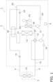
- the refrigeration apparatus 1 includes a first circuit 10, a second circuit 20, and a control unit 6.
- the refrigeration apparatus 1 of the present embodiment has a dual circuit including the vapor compression first circuit 10 and the vapor compression second circuit 20 and performs a dual refrigeration cycle.
- the first circuit 10 circulates the first refrigerant.
- the second circuit 20 circulates the second refrigerant.
- the critical temperature of the second refrigerant is lower than the critical temperature of the first refrigerant.
- the first circuit 10 and the second circuit 20 are thermally connected through a third heat exchanger 30.
- the heat source unit 2 includes a first heat exchanger 13 of the first circuit 10 and a second heat exchanger 22 of the second circuit 20.
- the second heat exchanger 22 is disposed on the leeward side of the first heat exchanger 13.
- the second heat exchanger 22 overlaps with a second region R2 (see Fig. 4 ) below the uppermost heat transfer tube of the first heat exchanger 13 as viewed in the stacking direction of the second heat exchanger 22 and the first heat exchanger 13.
- the critical temperature of the first refrigerant flowing through the first circuit 10 is lower than 45°C and is preferably 40°C or lower.
- the first refrigerant is non-flammable, non-toxic, or has the GWP of 500 or lower.
- the first refrigerant is, for example, a natural refrigerant, and preferably contains carbon dioxide.
- the first refrigerant of the present embodiment is a single refrigerant of carbon dioxide.
- the first circuit 10 is a main circuit configured to heat or cool the indoor air by the first refrigerant.
- the first compressor 11 is a device for compressing the first refrigerant and is, for example, a positive-displacement compressor of scroll type or the like capable of varying an operating capacity by inverter-controlling a compressor motor.
- the first compressor 11 discharges the first refrigerant in a supercritical state.
- the switching mechanism 12 is a device that switches between a first state (see the solid lines of the switching mechanism 12 in Fig. 1 ) in which the first heat exchanger 13 functions as a radiator for the first refrigerant and the fourth heat exchanger 15 functions as an evaporator for the first refrigerant, and a second state (see the broken lines of the switching mechanism 12 in Fig. 1 ) in which the first heat exchanger 13 functions as an evaporator for the first refrigerant and the fourth heat exchanger 15 functions as a radiator for the first refrigerant.
- the switching mechanism 12 is, for example, a four-way switching valve.
- the switching mechanism 12 connects the discharge side of the first compressor 11 to the gas side of the first heat exchanger 13 and connects the suction side of the first compressor 11 to the gas side of the fourth heat exchanger 15. Moreover, in the second state, the switching mechanism 12 connects the discharge side of the first compressor 11 to the gas side of the fourth heat exchanger 15 and connects the suction side of the first compressor 11 to the gas side of the first heat exchanger 13.
- the first heat exchanger 13 is a device for heat exchange performed between the first refrigerant and the outdoor air without mixing the first refrigerant with the outdoor air.
- the first refrigerant obtains cold heat or hot heat from the outdoor air.
- the first heat exchanger 13 is, for example, a fin-and-tube heat exchanger.
- the first expansion mechanism 14 is a device that decompresses the first refrigerant and is, for example, an electric expansion valve.
- the fourth heat exchanger 15 is a device for heat exchange between the first refrigerant and the indoor air and is, for example, a fin-and-tube heat exchanger.
- the first accumulator 16 is provided in the middle of a suction flow path connecting the switching mechanism 12 to the suction side of the first compressor 11.
- the first accumulator 16 separates the inflow refrigerant into a liquid refrigerant and a gas refrigerant and causes the gas refrigerant to flow to the suction side of the first compressor 11.
- the third heat exchanger 30 is a device for heat exchange performed between the first refrigerant and the second refrigerant without mixing the first refrigerant with the second refrigerant.
- the third heat exchanger 30 is a cascade heat exchanger and is, for example, a plate-type heat exchanger.
- the third heat exchanger 30 includes a first flow path 31 belonging to the first circuit 10 and a second flow path 32 belonging to the second circuit 20.
- the first flow path 31 forms a part of the first circuit 10
- the second flow path 32 forms a part of the second circuit 20.
- the configuration of the first circuit 10 includes the first flow path 31 of the third heat exchanger 30, and the configuration of the second circuit 20 includes the second flow path 32 of the third heat exchanger 30.
- One end side of the first flow path 31 is connected to the first heat exchanger 13, and the other end side thereof is connected to the fourth heat exchanger 15.
- the third heat exchanger 30 is intended to supercool the first refrigerant cooled by the first heat exchanger 13 and serves to assist the first circuit 10.
- the critical temperature of the second refrigerant flowing through the second circuit 20 is equal to or higher than 45°C and is preferably equal to or higher than 50°C.
- the second refrigerant is flammable.
- the second refrigerant is, for example, a hydrocarbon-based refrigerant, R1234yf, R1234ze, R32, or the like and is a single refrigerant of R290 in the present embodiment.
- the second circuit 20 forms a supercooling circuit during the cooling operation.
- the second circuit 20 is an assist circuit that assists the capacity of the first circuit 10 during the cooling operation.
- the second circuit 20 includes a second compressor 21, the second heat exchanger 22, a second expansion mechanism 23, a second accumulator 24, and the third heat exchanger 30.
- the second compressor 21 is a device for compressing the second refrigerant and is, for example, a positive-displacement compressor of scroll type or the like capable of varying an operating capacity by inverter-controlling a compressor motor.
- the second heat exchanger 22 is a device for heat exchange performed between the second refrigerant and the outdoor air without mixing the second refrigerant with the outdoor air.
- the second refrigerant obtains cold heat or hot heat from the outdoor air.
- the second heat exchanger 22 is, for example, a microchannel heat exchanger, a fin-and-tube heat exchanger, or the like.
- the second circuit 20 includes the second flow path 32 of the third heat exchanger 30.
- the gas side of the second flow path 32 is connected to the second compressor 21, and the liquid side thereof is connected to the second expansion mechanism 23.
- the second expansion mechanism 23 is a device that decompresses the second refrigerant and is, for example, an electric expansion valve.
- the second accumulator 24 is provided in the middle of a suction flow path connecting the third heat exchanger 30 to the suction side of the second compressor 21.
- the second accumulator 24 separates the inflow refrigerant into a liquid refrigerant and a gas refrigerant and causes the gas refrigerant to flow to the suction side of the second compressor 21.
- the heat source unit 2 is disposed in a space different from the space in which the utilization unit 3 is disposed.
- the heat source unit 2 is installed outdoors (on a rooftop of a building, near an outer wall surface of a building, or the like).
- the heat source unit 2 here is of a side-blowing type that takes in outdoor air from an opening (suction port O1) provided in the back surface of a casing 41 and an opening (suction port O2) provided in the left side surface and blows out the outdoor air having subjected to the heat exchange by the first heat exchanger 13 and the outdoor air having subjected to the heat exchange by the second heat exchanger 22 from an opening (blow-out port O3) provided in the front surface of the casing 41.
- the heat source unit 2 includes the above-described part of the first circuit 10, the second circuit 20, the casing 41, a partition plate 42, a fan 43, a motor 44, a first support 45, and a second support 46.
- the heat source unit 2 includes the first compressor 11, the switching mechanism 12, the first heat exchanger 13, the first expansion mechanism 14, the first accumulator 16, the second compressor 21, the second heat exchanger 22, the second expansion mechanism 23, the third heat exchanger 30, the fan 43, and the motor 44, which are illustrated in Fig. 1
- the casing 41, the partition plate 42, the first support 45, and the second support 46 which are illustrated in Fig. 2 .
- the casing 41 houses the first compressor 11, the switching mechanism 12, the first heat exchanger 13, the first expansion mechanism 14, the first accumulator 16, the second compressor 21, the second heat exchanger 22, the second expansion mechanism 23, the second accumulator 24, the third heat exchanger 30, the partition plate 42, the fan 43, the motor 44, the first support 45, and the second support 46.
- the casing 41 is a structural member that is a member serving as a framework for constructing the heat source unit 2.
- the casing 41 illustrated in Fig. 2 and Fig. 3 has a substantially rectangular parallelepiped shape. Specifically, the casing 41 includes a front panel 411, a top panel 412, a bottom plate 413, a side plate 414, and a back plate 415.
- the front panel 411 is a plate-like member forming the front surface of the casing 41.
- the blow-out port O3 is formed in the front panel 411.
- the blow-out port O3 is an opening for blowing out, to the outside of the casing 41, the outdoor air taken into the casing 41 from the outside.
- the top panel 412 is a plate-like member forming the upper surface of the casing 41.
- the bottom plate 413 is a plate-like member forming the lower surface of the casing 41.
- the top panel 412 and the bottom plate 413 face each other.
- the side plate 414 is a plate-like member forming the side surface of the casing 41.
- the suction port O2 is formed in the side plate 414. In Fig. 2 , the suction port O2 is formed in the left surface.
- the lower part of the side plate 414 is fixed to the bottom plate 413.
- the back plate 415 is a plate-like member forming the back surface of the casing 41.
- the suction port O1 is formed in the back plate 415.
- the lower part of the back plate 415 is fixed to the bottom plate 413.
- the partition plate 42 is a plate-like member extending in the up-down direction.
- the lower part of the partition plate 42 is fixed to the bottom plate 413 of the casing 41.
- the partition plate 42 partitions the inside of the casing 41 into a first chamber S1 and a second chamber S2.
- Each of the first chamber S1 and the second chamber S2 is a space defined by the front panel 411, the top panel 412, the bottom plate 413, the side plate 414, and the back plate 415 of the casing 41, and the partition plate 42.
- the first chamber S1 is a blowing chamber and is an air guide path through which air sucked from the suction ports O1 and O2 flows to the blow-out port O3.
- the first heat exchanger 13, the second heat exchanger 22, the fan 43, the motor 44, the first support 45, the second support 46, and the like are arranged in the first chamber S1.
- the second chamber S2 is a machine chamber.
- the first compressor 11, the second compressor 21, the switching mechanism 12, the first expansion mechanism 14, the second expansion mechanism 23, the first accumulator 16, the second accumulator 24, the third heat exchanger 30, and the like are arranged in the second chamber S2.
- first heat exchanger 13, the second heat exchanger 22, the fan 43, the motor 44, the first support 45, and the second support 46, which are arranged in the first chamber S1, will be mainly described.
- the first heat exchanger 13 is formed in an L-shape in top view. Specifically, the first heat exchanger 13 includes a part extending along the back surface of the casing 41 from the vicinity of the partition plate 42 to the vicinity of the left back corner portion of the casing 41, a part curved in the vicinity of the left back corner portion of the casing 41, and a portion extending along the side plate 414 from the vicinity of the left back corner portion of the casing 41 to the vicinity of the left front corner portion.
- the first heat exchanger 13 includes a first heat transfer tube 131, a plurality of first fins 132, and a pair of tube plates 141 and 142.
- the first heat transfer tube 131 is disposed in the up-down direction.
- the first heat transfer tube 131 includes a plurality of straight tube portions 131x formed in a linear shape and a plurality of bent tube portions 131y formed in a U-shape.
- the plurality of straight tube portions 131x are arranged at intervals in the up-down direction and extend in a direction orthogonal to the up-down direction.
- the plurality of bent tube portions 131y are arranged at end portions in the width direction (the right-left direction in Fig. 4 ) of the first heat exchanger 13 and connect two straight tube portions 131x arranged in the up-down direction to each other.
- the first heat transfer tube 131 is a circular tube, and a flow path through which the first refrigerant flows is formed in the first heat transfer tube 131.
- the first fin 132 is joined to the first heat transfer tube 131.
- the first fin 132 is joined to the straight tube portion 131x of the first heat transfer tube 131.
- the plurality of first fins 132 are arranged in a direction orthogonal to the up-down direction and extend in the up-down direction.
- the pair of tube plates 141 and 142 support the straight tube portions 131x of the first heat transfer tube 131.
- the tube plate 141 is connected to one end portion of the straight tube portion 131x, and the tube plate 142 is connected to the other end portion of the straight tube portion 131x.
- the tube plates 141 and 142 are arranged in parallel with the first fin 132 and extend in the up-down direction.
- the first heat exchanger 13 functions as a radiator for the first refrigerant, as indicated by arrows in FIG. 4 , the first refrigerant discharged from the first compressors 11 flows into an uppermost first heat transfer tube 131a, sequentially passes through the straight tube portion 131x and the bent tube portion 131y, and flows out from the lowermost first heat transfer tube 131 in the first heat exchanger 13. Therefore, the temperature of the first refrigerant increases from the lower side to the upper side.
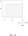
- the first heat exchanger 13 includes a first region R1 and the second region R2.
- the first region R1 includes the uppermost first heat transfer tube 131a and an area above the uppermost first heat transfer tube 131a.
- the first region R1 includes the uppermost first heat transfer tube 131a and the first fin 132 above the uppermost first heat transfer tube 131a.
- the second region R2 is located below the uppermost first heat transfer tube 131a.
- the second region includes the first heat transfer tube 131 except for the uppermost first heat transfer tube 131a and the first fin 132 below the uppermost first heat transfer tube 131a.
- the first region R1 includes the uppermost straight tube portion 131x, the upper portion of the uppermost bent tube portion 131y, the upper portion of the first fin 132, and the upper portions of the pair of tube plates 141 and 142.
- the second region R2 includes a plurality of straight tube portions 131x except for the uppermost straight tube portion 131x, a plurality of bent tube portions 131y below the upper portion of the uppermost bent tube portion 131y, the intermediate portion and the lower portion of the first fin 132, and the intermediate portion and the lower portion of the tube plates 141 and 142.
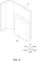
- the second heat exchanger 22 is formed in an I-shape in top view. Specifically, the second heat exchanger 22 extends along the back surface of the casing 41 from the vicinity of the partition plate 42 to an intermediate portion of the first chamber S1 in the right-left direction. In this way, the second heat exchanger 22 is disposed at the second chamber S2 side in the first chamber S1.
- the lateral center of the first chamber S1 is different from the lateral center of the second heat exchanger 22.
- the lateral center of the first chamber S1 is the center between the side plate 414 (the left-side panel in Fig. 2 ) and the partition plate 42 at the same position as the second heat exchanger 22 in the front-back direction.
- the lateral center of the second heat exchanger 22 is positioned closer to the second chamber S2 side (right side) than the lateral center of the first chamber S1. Therefore, the second heat exchanger 22 does not extend to the maximum extent to the left side of the first chamber S1 in the right-left direction.
- the second heat exchanger 22 has a substantially rectangular parallelepiped shape. Specifically, in the second heat exchanger 22, the length in the up-down direction is different from the length in the horizontal direction. In Fig. 5 and Fig. 6 , the length of the second heat exchanger 22 in the up-down direction is larger than the length in the horizontal direction thereof.
- the second heat exchanger 22 includes a plurality of second heat transfer tubes and a plurality of second fins.
- the second fin is joined to the second heat transfer tube.
- the first fin 132 of the first heat exchanger 13 and the second fin of the second heat exchanger 22 are arranged apart from each other. In the present embodiment, at least one of the first fin 132 and the second fin is disposed apart, and here, all of them are arranged apart. Therefore, the first fin 132 and the second fin are separate members.
- the fan 43 is disposed at a central portion of the first chamber S1 in the right-left direction and on the front side in the first chamber S1.
- the fan 43 sends air to the first heat exchanger 13 and the second heat exchanger 22.
- the fan 43 causes the outdoor air to flow through both the first heat exchanger 13 and the second heat exchanger 22.
- the fan 43 generates an air flow in which the outdoor air is guided to the first heat exchanger 13 and the second heat exchanger 22 for the heat exchange with the first refrigerant in the first heat exchanger 13 and for the heat exchange with the second refrigerant in the second heat exchanger 22, and then discharged to the outdoors.
- the air flow direction F is a first direction D in which the first heat exchanger 13 and the second heat exchanger 22 are stacked.
- the fan 43 is driven by the motor 44.
- the second heat exchanger 22 is disposed on the leeward side of the first heat exchanger 13. Specifically, the second heat exchanger 22 is disposed on the leeward side of the first heat exchanger 13 in the air flow direction F (see FIG. 2 ) generated by the fan 43. Here, the second heat exchanger 22 is disposed on the front side of the first heat exchanger 13.
- the first heat exchanger 13 and the second heat exchanger 22 are stacked in the first direction D (see Fig. 2 ).
- the first direction D is a direction orthogonal to a surface portion where the first heat exchanger 13 and the second heat exchanger 22 face each other.
- the first direction D is the front-back direction.
- the second heat exchanger 22 overlaps with the second region R2 of the first heat exchanger 13 as viewed in the first direction.
- the first region R1 of the first heat exchanger 13 is located above the second heat exchanger 22 as viewed in the first direction.
- the second heat exchanger 22 does not overlap with the first region R1 of the first heat exchanger 13 as viewed in the first direction.
- the second heat exchanger 22 overlaps only with the second region R2 of the first heat exchanger 13 as viewed in the first direction.
- the view in the first direction is a view in the direction where the first heat exchanger 13 and the second heat exchanger 22 overlap with each other.
- the second heat exchanger 22 overlaps with a part of the second region R2 of the first heat exchanger 13 as viewed in the first direction.
- the second heat exchanger 22 overlaps with the lower part of the second region R2 of the first heat exchanger 13 as viewed in the first direction.
- the entire second heat exchanger 22 is included in the second region R2 as viewed in the first direction.
- the fan 43 overlaps with the first heat exchanger 13 and the second heat exchanger 22 as viewed in the first direction.
- the fan 43 is supported by the first support 45.
- the second heat exchanger 22 is supported by the second support 46.
- the first support 45 and the second support 46 are separate members.
- the first support 45 supports the fan 43 by supporting the motor 44.
- the first support 45 includes a main body portion 45a that supports the motor from both ends in the right-left direction, and a motor base 45b.
- the main body portion 45a extends in the up-down direction.
- the upper end portion of the main body portion 45a is connected to the top panel 412 of the casing 41.
- the lower end portion of the main body portion 45a is connected to the motor base 45b.
- the motor base 45b is connected to the bottom plate 413 of the casing 41.
- the second support 46 supports the second heat exchanger 22 from both ends in the right-left direction.
- the second support 46 extends in the up-down direction.
- the second support 46 is connected to the structural member. Specifically, the upper end portion of the second support 46 is connected to the top panel 412 of the casing 41. The lower end portion of the second support 46 is connected to the bottom plate 413 of the casing 41.
- the utilization unit 3 illustrated in Fig. 1 is installed indoors (inside a building). As described above, the utilization unit 3 is connected to the utilization unit 3 through the connection pipes 4 and 5 and forms a part of the first circuit 10.
- the utilization unit 3 includes the fourth heat exchanger 15.
- the utilization unit 3 is installed, for example, by being embedded in or suspended from a ceiling in a room of a building or the like, or by being hung on a wall surface in a room.
- connection pipes 4 and 5 are refrigerant pipes constructed on site when the refrigeration apparatus 1 is installed in an installation place in a building or the like.
- One end of the liquid-side connection pipe 4 is connected to the liquid-side end portion of the heat source unit 2, and the other end of the connection pipe 4 is connected to the liquid-side end portion of the fourth heat exchanger 15 of the utilization unit 3.
- One end of the gas-side connection pipe 5 is connected to the gas-side end portion of the heat source unit 2, and the other end of the connection pipe 5 is connected to the gas-side end portion of the fourth heat exchanger 15 of the utilization unit 3.
- the control unit 6 is formed to control the above-described components of the heat source unit 2 and the utilization unit 3.
- the control unit 6 is formed by communicatively connecting an electric component unit or the like provided in the heat source unit 2 and a control board or the like provided in the utilization unit 3.
- the control unit 6 controls the components of the refrigeration apparatus 1 (here, the heat source unit 2 and the utilization unit 3). In other words, the control unit 6 controls the operation of the entire refrigeration apparatus 1.
- the control unit 6 is realized by a computer.
- the control unit 6 includes a control arithmetic device and a storage device.
- a control arithmetic device a processor such as a CPU or a GPU can be used.
- the control arithmetic device reads a program stored in the storage device and performs predetermined image processing and arithmetic processing in accordance with the program. Further, the control arithmetic device can write arithmetic results to the storage device and read information stored in the storage device in accordance with the program.
- the operation of the refrigeration apparatus 1 will be described with reference to Fig. 1 to Fig. 8 .
- the refrigeration apparatus 1 can perform, for indoor air-conditioning, a cooling operation for cooling indoor air and a heating operation for heating indoor air. In the cooling operation and the heating operation, the operation of the refrigeration apparatus 1 is controlled by the control unit 6.
- the first refrigerant in the supercritical state discharged from the first compressor 11 is sent to the first heat exchanger 13 through the switching mechanism 12.
- the first refrigerant sent to the first heat exchanger 13 is cooled through heat exchange with the outdoor air supplied by the fan 43, thereby radiating heat.
- the first refrigerant having radiated heat in the first heat exchanger 13 is sent to the first flow path 31 of the third heat exchanger 30.
- the first refrigerant sent to the first flow path 31 is further cooled by heat exchange with the second refrigerant flowing through the second flow path 32 in the third heat exchanger 30.
- the first refrigerant further cooled in the third heat exchanger 30 is decompressed by the first expansion mechanism 14 and then flows out of the heat source unit 2.
- the first refrigerant having flowed out from the heat source unit 2 flows into the utilization unit 3 through the liquid-side connection pipe 4.
- the first refrigerant is sent to the fourth heat exchanger 15.
- the first refrigerant sent to the fourth heat exchanger 15 is evaporated by being heated through heat exchange with the indoor air.
- the first refrigerant evaporated in the fourth heat exchanger 15 flows out from the utilization unit 3.
- the first refrigerant having flowed out from the utilization unit 3 flows into the heat source unit 2 through the gas-side connection pipe 5.
- the first refrigerant is sucked into the first compressor 11 again through the switching mechanism 12 and the first accumulator 16.
- the second refrigerant discharged from the first compressor 11 is sent to the second heat exchanger 22.
- the second refrigerant sent to the second heat exchanger 22 is cooled through heat exchange with the outdoor air supplied by the fan 43, thereby radiating heat.
- This outdoor air is the air having passed through the second region R2 of the first heat exchanger 13.
- the second refrigerant having radiated heat in the second heat exchanger 22 is decompressed by the second expansion mechanism 23 and then sent to the second flow path 32 of the third heat exchanger 30.
- the second refrigerant sent to the second flow path 32 is evaporated by being heated through heat exchange with the first refrigerant flowing through the first flow path 31 in the third heat exchanger 30.
- the second refrigerant evaporated in the third heat exchanger 30 is sucked into the second compressor 21 again through the second accumulator 24.
- the flow of the refrigerant in the first heat exchanger 13 during the cooling operation will be described mainly with reference to Fig. 4 .
- the first heat exchanger 13 functions as a radiator for the first refrigerant
- the first refrigerant discharged from the first compressors 11 flows into the straight tube portion 131x of the uppermost first heat transfer tube 131a.
- heat of the first refrigerant flowing through the uppermost straight tube portion 131x is partially radiated by heat exchange with the outdoor air, and the first refrigerant reaches the uppermost bent tube portion 131y.
- the first refrigerant turns at the bent tube portion 131y and flows to the lower straight tube portion 131x.
- Heat of the first refrigerant flowing through the lower straight tube portion 131x is further radiated by heat exchange again with the outdoor air, and the first refrigerant reaches the lower bent tube portion 131y. In this way, the first refrigerant sequentially flows downward, reaches the lowermost straight tube portion 131x, and flows out of the first heat exchanger 13.
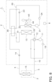
- the switching mechanism 12 is switched to the second state (the switching mechanism 12 is in the state indicated by the broken lines) so that the first heat exchanger 13 functions as an evaporator for the first refrigerant and the fourth heat exchanger 15 functions as a radiator for the first refrigerant.
- the second compressors 21 is not started, and the second refrigerant in the second circuit 20 is not circulated.
- the second expansion mechanism 23 is fully closed.
- the first refrigerant in the supercritical state discharged from the first compressor 11 flows out of the heat source unit 2 through the switching mechanism 12.
- the refrigerant having flowed out from the heat source unit 2 flows into the utilization unit 3 through the gas-side connection pipe 5.
- the first refrigerant is sent to the fourth heat exchanger 15.
- the first refrigerant sent to the fourth heat exchanger 15 is cooled through heat exchange with the indoor air, thereby radiating heat.
- the first refrigerant whose heat has been radiated in the fourth heat exchanger 15 flows out from the utilization unit 3.
- the first refrigerant having flowed out from the utilization unit 3 flows into the heat source unit 2 through the liquid-side connection pipe 4.
- the first refrigerant is sent to the first heat exchanger 13 through the first expansion mechanism 14 and the first flow path 31 of the third heat exchanger 30.
- the first refrigerant sent to the first heat exchanger 13 is evaporated by being heated through heat exchange with the outdoor air supplied by the fan 43.
- the first refrigerant evaporated in the first heat exchanger 13 is sucked into the first compressor 11 again through the switching mechanism 12 and the first accumulator 16.
- the heat source unit 2 is the heat source unit 2 of the refrigeration apparatus 1 including the first circuit 10 and the second circuit 20.
- the first circuit 10 circulates the first refrigerant having a critical temperature of lower than 45°C and includes the first heat exchanger 13.
- the second circuit 20 circulates the second refrigerant having a critical temperature of equal to or higher than 45°C and includes the second heat exchanger 22.
- the heat source unit 2 includes the first heat exchanger 13 and the second heat exchanger 22.
- the first heat exchanger 13 includes a plurality of first heat transfer tubes 131 (heat transfer tubes).
- the plurality of first heat transfer tubes 131 are arranged in the up-down direction.
- the second heat exchanger 22 is disposed on the leeward side of the first heat exchanger 13.
- the first heat exchanger 13 and the second heat exchanger 22 are stacked in the first direction D.
- the first heat exchanger 13 includes the first region R1 and the second region R2.
- the first region R1 includes the uppermost first heat transfer tube 131a and an area above the uppermost first heat transfer tube 131a.
- the second region R2 is located below the uppermost first heat transfer tube 131a.
- the second heat exchanger 22 overlaps with the second region R2 as viewed in the first direction.
- the first refrigerant having a critical temperature of lower than 45°C has a high heat radiation temperature. Therefore, in a case where the first refrigerant is subjected to heat exchange with air serving as a heat source in the radiator, when the air temperature is high, the phase of the first refrigerant does not change in the radiator, and the enthalpy difference by the heat exchange decreases, resulting in poor efficiency. Therefore, in the present embodiment, the second circuit 20 in which the second refrigerant having a critical temperature of equal to or higher than 45°C circulates is used to supercool the first refrigerant, thereby increasing the cooling capacity to be obtained.
- the air is heated by the first refrigerant flowing through the first heat transfer tube 131 of the first heat exchanger 13.
- the air has the highest temperature in the vicinity of the uppermost stage of the first heat exchanger 13.
- the temperature thereof is highest at the uppermost stage (inlet portion) and gradually decreases toward the downstream side.
- the second heat exchanger 22 is disposed on the leeward side of the second region R2 below the uppermost first heat transfer tube 131a of the first heat exchanger 13 as viewed in the first direction, which is the direction in which the first heat exchanger 13 and the second heat exchanger 22 overlap with each other.
- This allows the second refrigerant in the second heat exchanger 22 to avoid heat exchange with the air having the highest temperature. Therefore, it is possible to suppress the deterioration of heat exchange efficiency between the second refrigerant and the air.
- the heat source unit 2 further includes the first compressor 11, the second compressor 21, the casing 41, and the partition plate 42.
- the first compressor 11 compresses the first refrigerant.
- the second compressor 21 compresses the second refrigerant.
- the casing 41 houses the first heat exchanger 13 and the second heat exchanger 22.
- the partition plate 42 partitions the inside of the casing 41 into the first chamber S1 and the second chamber S2.
- the first heat exchanger 13 and the second heat exchanger 22 are arranged in the first chamber S1.
- the first compressor 11 and the second compressor 21 are arranged in the second chamber S2. In the first chamber S1, the second heat exchanger 22 is disposed at the second chamber S2 side.
- the second heat exchanger 22 is disposed at the second chamber S2 side, which facilitates connection to the member disposed in the second chamber S2.
- the heat source unit 2 further includes the fan 43, the first support 45, and the second support 46.
- the fan 43 sends air to the second heat exchanger 22.
- the first support 45 supports the fan 43.
- the second support 46 supports the second heat exchanger 22.
- the fan 43 is supported by the first support 45 and the second heat exchanger 22 is supported by the second support 46, which facilitates the attachment of the fan 43 and the second heat exchanger 22 to the first support 45 and second support 46.
- the second support 46 is preferably connected to a structural member.
- the first heat exchanger 13 further includes the first fin 132.
- the second heat exchanger 22 includes the second fin.
- the first fin 132 and the second fin are arranged apart from each other.
- first fin 132 of the first heat exchanger 13 and the second fin of the second heat exchanger 22 are not common, which suppresses heat exchange between the first fin 132 and the second fin. Therefore, it is possible to further suppress the deterioration of heat exchange efficiency in the first heat exchanger 13 and the second heat exchanger 22.
- the heat source unit 2 according to the present embodiment further includes the third heat exchanger 30.
- the third heat exchanger 30 performs heat exchange between the first refrigerant and the second refrigerant.
- the second heat exchanger 22 preferably has the length in the up-down direction different from the length in the horizontal direction.
- the second heat exchanger 22 in a case where the second heat exchanger 22 has the length in the up-down direction smaller than the length in the horizontal direction, the second heat exchanger 22 can be disposed so as to increase the region not overlapping with the high-temperature portion in the first heat exchanger 13. In a case where the second heat exchanger 22 has the length in the up-down direction larger than the length in the horizontal direction, it is effective when there is a restriction on the installation position of the second heat exchanger 22.
- the first circuit 10 further includes the first compressor 11.
- the first compressor 11 discharges the first refrigerant in a supercritical state. In this way, a refrigerant in a supercritical state may be used as the first refrigerant.
- the first refrigerant preferably includes a carbon dioxide refrigerant.
- the first refrigerant containing carbon dioxide having a high radiation temperature it is possible to use the first refrigerant containing carbon dioxide having a high radiation temperature.
- the second refrigerant is preferably flammable. In this way, a flammable refrigerant may be used as the second refrigerant.
- the second refrigerant preferably includes a hydrocarbon-based refrigerant.
- the second refrigerant including a hydrocarbon-based refrigerant having a low condensation temperature.
- the refrigeration apparatus 1 includes the heat source unit 2 and the utilization unit 3.
- the heat source unit 2 is any of the above-described heat source units.
- the utilization unit 3 is connected to the heat source unit 2.
- the above-described heat source unit 2 is provided, which suppresses the deterioration of heat exchange efficiency.
- the second heat exchanger 22 does not extend to the maximum extent to the left side of the first chamber S1 in the right-left direction, but the present disclosure is not limited thereto.
- the width of the second heat exchanger 22 in the right-left direction has a maximum length.
- the second heat exchanger 22 extends so as to face a portion of the first heat exchanger 13 that extends from the partition plate 42 to the vicinity of the left back corner portion of the casing 41. Note that the second heat exchanger 22 extends in the right-left direction to such an extent that it does not contact the first heat exchanger 13.
- the entire second heat exchanger 22 is included in the second region R2.
- the present disclosure is not particularly limited thereto as long as the second heat exchanger 22 overlaps with at least a part of the second region R2 as viewed in the first direction.
- the lower end of the second heat exchanger 22 and the lower end of the first heat exchanger are the same in the up-down direction, but the present disclosure is not limited thereto as long as they do not overlap with the first region R1.
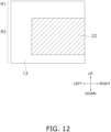
- the lower end of the first heat exchanger 13 may be positioned above the lower end of the second heat exchanger 22. However, in the present modification, as illustrated in Fig. 12 , the lower end of the first heat exchanger 13 is positioned below the lower end of the second heat exchanger 22.
- the second support 46 supports both left and right end portions of the second heat exchanger 22, but the present disclosure is not limited thereto.
- the lower end portion of the second support 46 is connected to the upper end portion of the second heat exchanger 22, and the upper end portion of the second support 46 is connected to the top panel 412 of the casing 41.
- the motor base 45b of the first support supports the lower end portion of the second heat exchanger 22.
- the second support 46 connected to the main body portion 45a of the first support 45 and extending in the front-back direction supports the upper end portion of the second heat exchanger 22.
- the heat source unit 2 further includes the fan 43, the motor 44, and the first support 45.
- the fan 43 sends air to the second heat exchanger 22.
- the motor 44 drives the fan 43.
- the first support 45 supports the motor 44.
- the first support 45 further supports the second heat exchanger 22.
- first fin 132 of the first heat exchanger 13 and the second fin of the second heat exchanger 22 are separate members, but the present disclosure is not limited thereto. In the present modification, the first fin and the second fin are integrally formed.
- first fin and at least a part of the second fin are connected to each other.
- first fin and the second fin are connected to each other, there may be a portion in which a hole is formed like a perforation.
- the first heat exchanger 13 further includes the first fin.
- the second heat exchanger 22 includes the second fin. The first fin and the second fin are integrally formed.
- integral indicates that the first fin and the second fin are at least partially connected to each other, and a case where a hole is formed like a perforation, for example, is included.
- first fin of the first heat exchanger 13 and the second fin of the second heat exchanger 22 are common, which facilitates manufacturing of the first heat exchanger 13 and the second heat exchanger 22.
- the common fan 43 sends air to the first heat exchanger 13 and the second heat exchanger 22, but the present disclosure is not limited thereto.
- the fan causing air to flow through the first heat exchanger 13 and the fan causing air to flow through the second heat exchanger 22 are separately provided.
- the above-described embodiment exemplifies the first heat exchanger 13 whose temperature increases from the lower side to the upper side in a case where the first heat exchanger 13 functions as a radiator for the first refrigerant, but the present disclosure is not limited thereto.
- a plurality of first heat exchangers 13 of the above-described embodiment in which the temperature increases from the lower side to the upper side are stacked in the up-down direction.
- a first heat exchanger 13a of the present modification includes a plurality of first heat exchangers 13 of the above-described embodiment, an antifreezing path 135, a flow divider 136, and a collecting pipe 137.
- the antifreezing path 135 is disposed below the plurality of first heat exchangers 13 stacked in the up-down direction. In other words, in the first heat exchanger 13a, the antifreezing path 135 is provided at the lowermost stage. In a case where the first heat exchanger 13b functions as an evaporator for the first refrigerant, the antifreezing path 135 serves as an antifreezing pipe.
- the collecting pipe 137 distributes the first refrigerant flowing into the first heat exchanger 13a and causes the first refrigerant to flow to the upper portion of each of the plurality of first heat exchangers 13.
- the first refrigerant flows from the upper side to the lower side, similarly to the above-described embodiment.
- the first refrigerant flowing out from the lower portion of each first heat exchanger 13 is collected in the flow divider 136 and flows out from the first heat exchanger 13a.
- the first heat exchanger 13a includes the first region R1 formed by the uppermost first heat transfer tube 131a of the first heat exchanger 13a and an area above the uppermost first heat transfer tube 131a, and the second region R2 below the uppermost first heat transfer tube 131a.
- the uppermost first heat transfer tube 131a which is the boundary of the first region R1, is the first heat transfer tube positioned at the uppermost stage in the uppermost first heat exchanger 13 among the plurality of first heat exchangers 13.
- the air has the highest temperature in the vicinity of the uppermost stage of each first heat exchanger 13.
- the second heat exchanger 22 is disposed on the leeward side of the second region R2 below the uppermost first heat transfer tube 131a of the first heat exchanger 13a as viewed in the first direction, which is the direction in which the first heat exchanger 13 and the second heat exchanger 22 overlap with each other. This allows the second refrigerant flowing in the second heat exchanger 22 to avoid heat exchange with the air having the highest temperature at least in the vicinity of the upper most stage. Therefore, it is possible to suppress the deterioration of heat exchange efficiency between the second refrigerant and the air.
- the inlets of the first heat exchangers 13 may be gathered in the upper portion. In this case, the vicinity of the inlet portion of the first refrigerant has the highest temperature.
- the second heat exchanger 22 is preferably disposed so as not to overlap with the inlet portion of the first refrigerant.
- the first heat exchanger 13 is a fin-and-tube heat exchanger, but the present disclosure is not limited thereto.
- any heat exchanger such as a microchannel heat exchanger may be adopted.
- a first heat exchanger 13b of the present modification is a microchannel heat exchanger.
- the first heat exchanger 13b includes a plurality of first heat transfer tubes 131, a plurality of first fins 132, and a first header 133 and a second header 134 that are illustrated in Fig. 17 .
- the plurality of first heat transfer tubes 131 are arranged in the up-down direction. Specifically, the plurality of first heat transfer tubes 131 are arranged at intervals in the up-down direction and extend in a direction orthogonal to the up-down direction.
- the first heat transfer tube 131 has a flat shape, and the first heat transfer tube 131 includes a plurality of flow paths through which the first refrigerant flows.
- the first fin 132 is joined to the first heat transfer tube 131.
- the plurality of first fins 132 are arranged in a direction orthogonal to the up-down direction and extend in the up-down direction.
- the first header 133 is connected to one end portion of the first heat transfer tube 131, and the second header 134 is connected to the other end portion of the first heat transfer tube 131.
- the first header 133 and the second header 134 extend in the up-down direction.
- the first header 133 is an inlet/outlet header having an inlet portion and an outlet portion for the first refrigerant.
- the first header 133 is partitioned into an upper region 133a, an intermediate region 133b, and a lower region 133c.
- the upper region 133a, the intermediate region 133b, and the lower region 133c are arranged in the up-down direction.
- the inlet portion for the first refrigerant is connected to the upper region 133a of the first header 133, and the outlet portion for the first refrigerant is connected to the lower region 133c of the first header 133.
- the second header 134 is a return header.
- the second header 134 is partitioned into an upper region 134a and a lower region 134b.
- the upper region 134a and the lower region 134b are arranged in the up-down direction.
- the first heat exchanger 13b has a first flow path group X, a second flow path group Y, a third flow path group Z, and a fourth flow path W, which are arranged in the up-down direction.
- each of the first heat transfer tubes arranged in the up-down direction belongs to any of the plurality of flow path groups X, Y, and Z and the fourth flow path W.
- the first flow path group X is the uppermost flow path group, and a plurality of first heat transfer tubes 131 belong thereto.
- the first flow path group X includes the uppermost first heat transfer tube 131a.
- One end of the first heat transfer tube 131 belonging to the first flow path group X is connected to the upper region 133a of the first header 133, and the other end thereof is connected to the upper region 134a of the second header 134.
- the second flow path group Y is the flow path group positioned below the first flow path group X, and a plurality of first heat transfer tubes 131 belong thereto.
- One end of the first heat transfer tube 131 belonging to the second flow path group Y is connected to the intermediate region 133b of the first header 133, and the other end thereof is connected to the upper region 134a of the second header.
- the third flow path group Z is a flow path group positioned below the second flow path group Y, and a plurality of first heat transfer tubes 131 belong thereto.
- One end of the first heat transfer tube 131 belonging to the third flow path group Z is connected to the intermediate region 133b of the first header 133, and the other end thereof is connected to the lower region 134b of the second header.
- the fourth flow path W is the lowermost flow path, and one or more first heat transfer tubes 131 belong thereto.
- the first heat transfer tube 131 belonging to the fourth flow path W serves as an antifreezing pipe in a case where the first heat exchanger 13b functions as an evaporator for the first refrigerant.
- One end of the first heat transfer tube 131 belonging to the fourth flow path W is connected to the lower region 133c of the first header 133, and the other end thereof is connected to the lower region 134b of the second header.
- the first refrigerant discharged from the first compressor 11 flows through the upper region 133a of the first header 133, the first flow path group X, the upper region 134a of the second header 134, the second flow path group Y, the intermediate region 133b of the first header 133, the third flow path group Z, the lower region 134b of the second header 134, the fourth flow path W, and the lower region 133c of the first header 133 in this order, as indicated by the arrows in Fig. 17 . Therefore, the temperature of the first refrigerant is higher in the first flow path group X, the second flow path group Y, the third flow path group Z, and the fourth flow path W in this order.
- the first heat exchanger 13b includes the first region R1 and the second region R2.
- the first region R1 includes an upper portion of the first flow path group X, an upper portion of the upper region 133a of the first header 133, and an upper portion of the upper region 134a of the second header 134.
- the second region R2 includes a lower portion of the first flow path group X, the second flow path group Y, the third flow path group Z, the fourth flow path W, a lower portion of the upper region 133a, the intermediate region 133b, and the lower region 133c of the first header 133, and a lower portion of the upper region 134a and the lower region 134b of the second header 134.
- the refrigerant flowing through the first flow path group X has a higher temperature than the refrigerant flowing through the second flow path group Y, the third flow path group Z, and the fourth flow path W in the first heat exchanger 13. Therefore, the air subjected to heat exchange with the first refrigerant flowing through the first flow path group X has a high temperature. Therefore, the second heat exchanger 22 is preferably disposed so as not to overlap with the first flow path group X as viewed in the first direction.
- the first refrigerant turns at the upper region 134a and flows to the plurality of first heat transfer tubes 131 belonging to the lower second flow path group Y.
- the heat of the first refrigerant flowing through the second flow path group Y is further radiated by heat exchange again with the outdoor air, and the first refrigerant reaches the intermediate region 133b of the first header 133.
- the first refrigerant turns at the intermediate region 133b and flows to the plurality of first heat transfer tubes 131 belonging to the lower third flow path group Z.
- the heat of the first refrigerant flowing through the third flow path group Z is further radiated by heat exchange again with the outdoor air, and the first refrigerant reaches the lower region 134b of the second header 134.
- the first refrigerant turns at the lower region 134b and flows to the first heat transfer tube 131 belonging to the lower fourth flow path W.
- the first refrigerant flowing through the fourth flow path W reaches the lower region 133c of the first header 133 and flows out from the first heat exchanger 13b.
- the above-described embodiment has exemplified the heat source unit of a side-blowing type, but the present disclosure is not limited thereto.
- the heat source unit of the present modification is of a top-blown type.
- the fan 43 is disposed above the first heat exchanger 13 and the second heat exchanger 22.
- air is taken in from the opening provided on the side surface of the casing 41 and passes through the first heat exchanger 13 and the second heat exchanger 22.
- the air subjected to heat exchange with the first refrigerant in the first heat exchanger 13 and the air subjected to heat exchange with the second refrigerant in the second heat exchanger 22 are blown out upward from the opening provided in the upper surface of the casing 41. Therefore, the air flow direction F generated by the fan 43 includes the first direction in which the first heat exchanger 13 and the second heat exchanger 22 are stacked.
- the second heat exchanger 22 overlaps with the second region R2 of the first heat exchanger 13 as viewed in the first direction, which is the direction in which the first heat exchanger 13 and the second heat exchanger 22 overlap with each other.
- the operation of the second circuit 20 is stopped in the heating operation, but the present disclosure is not limited thereto.
- the refrigeration apparatus of the present disclosure may operate the second circuit 20 in the heating operation.
- the second circuit 20 is operated in the cooling operation, but the present disclosure is not limited thereto.
- the refrigeration apparatus of the present disclosure may stop the operation of the second circuit 20 in the cooling operation.
- the above-described embodiment has exemplified the refrigeration apparatus 1 in which one utilization unit 3 is connected to one heat source unit 2, but the present disclosure is not limited thereto.
- a plurality of utilization units are connected to one heat source unit.
- the above-described embodiment has exemplified the refrigeration apparatus 1 performing the cooling operation and heating operation, but the present disclosure is not limited thereto.
- the refrigeration apparatus of the present disclosure may further perform a dehumidifying operation.
- the refrigeration cycle apparatus of the present disclosure may be an air-conditioning apparatus only for cooling.
- the heat source unit is applied to the air-conditioning apparatus as a refrigeration apparatus, but the present disclosure is not limited thereto.
- the heat source unit of the present disclosure may be applied to a refrigeration apparatus such as a hot water supply apparatus, a floor heating apparatus, or a refrigerator.
Landscapes
- Engineering & Computer Science (AREA)
- Physics & Mathematics (AREA)
- Thermal Sciences (AREA)
- Mechanical Engineering (AREA)
- General Engineering & Computer Science (AREA)
- Chemical & Material Sciences (AREA)
- Combustion & Propulsion (AREA)
- Geometry (AREA)
- Other Air-Conditioning Systems (AREA)
- Heat-Exchange Devices With Radiators And Conduit Assemblies (AREA)
- Air Filters, Heat-Exchange Apparatuses, And Housings Of Air-Conditioning Units (AREA)
Abstract
Description
- The present invention relates to a heat source unit and a refrigeration apparatus.
- The refrigeration cycle apparatus of PTL 1 (International Publication No. 2022/211078) includes the first refrigerant circuit using the first refrigerant and the second refrigerant circuit using the second refrigerant. PTL 1 describes that in the air flow direction of the outdoor fan 9, the second
outdoor heat exchanger 23 in the second refrigerant circuit is disposed on the windward side of the first outdoor heat exchanger 18 in the first refrigerant circuit. - The above-described PTL 1 does not refer to the relation between the position of the first outdoor heat exchanger 18 in the up-down direction and the position of the second
outdoor heat exchanger 23 in the up-down direction. - A heat source unit according to a first aspect is a heat source unit of a refrigeration apparatus including a first circuit and a second circuit. The first circuit circulates a first refrigerant having a critical temperature of lower than 45°C and includes a first heat exchanger. The second circuit circulates a second refrigerant having a critical temperature of equal to or higher than 45°C and includes a second heat exchanger. The heat source unit includes the first heat exchanger and the second heat exchanger. The first heat exchanger includes a plurality of heat transfer tubes. The plurality of heat transfer tubes are arranged in an up-down direction. The second heat exchanger is disposed on the leeward side of the first heat exchanger. The first heat exchanger and the second heat exchanger are stacked in a first direction. The first heat exchanger includes a first region and a second region. The first region includes the uppermost heat transfer tube and an area above the uppermost heat transfer tube. The second region is located below the uppermost heat transfer tube. The second heat exchanger overlaps with the second region as viewed in the first direction.
- When the refrigeration apparatus including such a heat source unit of the first aspect is operated for cooling operation, for example, the air is heated by the first refrigerant flowing through the heat transfer tube of the first heat exchanger. Here, the air has the highest temperature in the vicinity of the uppermost stage of the first heat exchanger. However, in the heat source unit of the first aspect, the second heat exchanger is disposed on the leeward side of the second region below the uppermost heat transfer tube of the first heat exchanger as viewed in the first direction, which is the direction in which the first heat exchanger and the second heat exchanger overlap with each other. This allows the second refrigerant in the second heat exchanger to avoid heat exchange with the air having the highest temperature. Therefore, it is possible to suppress the deterioration of heat exchange efficiency between the second refrigerant and the air.
- The heat source unit according to a second aspect is the heat source unit of the first aspect and further includes a first compressor, a second compressor, a casing, and a partition plate. The first compressor compresses the first refrigerant. The second compressor compresses the second refrigerant. The casing houses the first heat exchanger, the second heat exchanger, the first compressor, and the second compressor. The partition plate partitions the inside of the casing into a first chamber and a second chamber. The first heat exchanger and the second heat exchanger are arranged in the first chamber. The first compressor and the second compressor are arranged in the second chamber. In the first chamber, the second heat exchanger is disposed at the second chamber side.
- In the heat source unit of the second aspect, the second heat exchanger is disposed at the second chamber side, which facilitates connection to a member disposed in the second chamber.
- A heat source unit according to a third aspect is the heat source unit of the first aspect or the second aspect and further includes a fan, a first support, and a second support. The fan sends air to the second heat exchanger. The first support supports the fan. The second support supports the second heat exchanger.
- In the heat source unit according to the third aspect, in a case where the length of the fan in the up-down direction is different from the length of the second heat exchanger in the up-down direction, the fan is supported by the first support and the second heat exchanger is supported by the second support, which facilitates the attachment of the fan and the second heat exchanger to the first and second supports.
- A heat source unit according to a fourth aspect is the heat source unit of the third aspect, in which the second support is connected to a structural member.
- In the heat source unit of the fourth aspect, it is possible to support the second heat exchanger by using the second support connected to the structural member.
- A heat source unit according to a fifth aspect is the heat source unit of the first aspect or the second aspect and further includes a fan, a motor, and a first support. The fan sends air to the second heat exchanger. The motor drives the fan. The first support supports the motor. The first support further supports the second heat exchanger.
- In the heat source unit of the fifth aspect, it is possible to support the second heat exchanger by using the first support that supports the motor driving the fan.
- A heat source unit according to a sixth aspect is the heat source unit of any one of the first aspect to the fifth aspect, in which the first heat exchanger further includes a first fin. The second heat exchanger includes a second fin. The first fin and the second fin are arranged apart from each other.
- In the heat source unit of the sixth aspect, the first fin of the first heat exchanger and the second fin of the second heat exchanger are not common, which suppresses heat exchange between the first fin and the second fin. Therefore, it is possible to further suppress the deterioration of heat exchange efficiency in the first heat exchanger and the second heat exchanger.
- A heat source unit according to a seventh aspect is the heat source unit of any one of the first aspect to the fifth aspect, in which the first heat exchanger further includes a first fin. The second heat exchanger includes a second fin. The first fin and the second fin are integrally formed.
- In the heat source unit of the seventh aspect, the first fin of the first heat exchanger and the second fin of the second heat exchanger are common, which facilitates manufacturing.
- A heat source unit according to an eighth aspect is the heat source unit of any one of the first aspect to the seventh aspect and further includes a third heat exchanger. The third heat exchanger performs heat exchange between the first refrigerant and the second refrigerant.
- As in the heat source unit of the eighth aspect, it is also possible to form a dual circuit in which the first circuit and the second circuit are connected by the third heat exchanger.
- A heat source unit according to a ninth aspect is the heat source unit of any one of the first aspect to the eighth aspect, in which in the second heat exchanger, a length in the up-down direction is different from a length in a horizontal direction.
- In the heat source unit of the ninth aspect, in a case where the second heat exchanger has the length in the up-down direction smaller than the length in the horizontal direction, the second heat exchanger can be disposed so as to increase the region not overlapping with the high-temperature portion in the first heat exchanger. In a case where the second heat exchanger has the length in the up-down direction larger than the length in the horizontal direction, it is effective when there is a restriction on the installation position of the second heat exchanger.
- A heat source unit according to a tenth aspect is the heat source unit of any one of the first aspect to the ninth aspect, in which the first circuit further includes a first compressor. The first compressor discharges the first refrigerant in a supercritical state.
- As in the heat source unit of the tenth aspect, a refrigerant in a supercritical state may be used as the first refrigerant.
- A heat source unit according to an eleventh aspect is the heat source unit of the tenth aspect, in which the first refrigerant includes a carbon dioxide refrigerant.
- In the heat source unit of the eleventh aspect, it is possible to use the first refrigerant containing carbon dioxide having a high radiation temperature.
- A heat source unit according to a twelfth aspect is the heat source unit of any one of the first aspect to the eleventh aspect, in which the second refrigerant is flammable.
- As in the heat source unit of the twelfth aspect, a flammable refrigerant may be used as the second refrigerant.
- A heat source unit according to a thirteenth aspect is the heat source unit of the twelfth aspect, in which the second refrigerant includes a hydrocarbon-based refrigerant.
- In the heat source unit of the thirteenth aspect, it is possible to use the second refrigerant including a hydrocarbon-based refrigerant having a low condensation temperature.
- A refrigeration apparatus according to a fourteenth aspect includes a heat source unit and a utilization unit. The heat source unit is the heat source unit according to any one of the first aspect to the thirteenth aspect. The utilization unit is connected to the heat source unit.
- The refrigeration apparatus of the fourteenth aspect includes the above-described heat source unit, which suppresses the deterioration of heat exchange efficiency.
-
- [
Fig. 1] Fig. 1 is a schematic configuration diagram of a refrigeration apparatus according to an embodiment of the present disclosure. - [
Fig. 2] Fig. 2 is a schematic sectional view of a heat source unit. - [
Fig. 3] Fig. 3 is a schematic sectional view of the heat source unit. - [
Fig. 4] Fig. 4 is a schematic view of a first heat exchanger. - [
Fig. 5] Fig. 5 is a perspective view of the first heat exchanger and a second heat exchanger. - [
Fig. 6] Fig. 6 is a schematic view of the first heat exchanger and the second heat exchanger as viewed in a first direction. - [
Fig. 7] Fig. 7 is a view illustrating operations in a cooling operation of the refrigeration apparatus. - [
Fig. 8] Fig. 8 is a view illustrating operations in a heating operation of the refrigeration apparatus. - [
Fig. 9] Fig. 9 is a perspective view of a first heat exchanger and a second heat exchanger according to a first modification. - [
Fig. 10] Fig. 10 is a schematic view of the first heat exchanger and the second heat exchanger according to the first modification as viewed in a first direction. - [
Fig. 11] Fig. 11 is a schematic view of a first heat exchanger and a second heat exchanger according to a second modification as viewed in a first direction. - [
Fig. 12] Fig. 12 is a schematic view of a first heat exchanger and a second heat exchanger according to a third modification as viewed in a first direction. - [
Fig. 13] Fig. 13 is a schematic sectional view of a heat source unit according to a fourth modification. - [
Fig. 14] Fig. 14 is a schematic sectional view of a heat source unit according to a fifth modification. - [
Fig. 15] Fig. 15 is a schematic view of a first heat exchanger according to an eighth modification. - [
Fig. 16] Fig. 16 is a perspective view of a first heat exchanger according to a ninth modification. - [
Fig. 17] Fig. 17 is a schematic view of the first heat exchanger according to the ninth modification. - [
Fig. 18] Fig. 18 is a schematic sectional view of a heat source unit according to a tenth modification. - As illustrated in
Fig. 1 , a refrigeration apparatus 1 according to an embodiment of the present disclosure is an apparatus used to cool and heat a room of a building or the like by performing a vapor compression refrigeration cycle operation. - The refrigeration apparatus 1 includes a
first circuit 10, asecond circuit 20, and acontrol unit 6. The refrigeration apparatus 1 of the present embodiment has a dual circuit including the vapor compressionfirst circuit 10 and the vapor compressionsecond circuit 20 and performs a dual refrigeration cycle. - The
first circuit 10 circulates the first refrigerant. Thesecond circuit 20 circulates the second refrigerant. The critical temperature of the second refrigerant is lower than the critical temperature of the first refrigerant. Thefirst circuit 10 and thesecond circuit 20 are thermally connected through athird heat exchanger 30. - The refrigeration apparatus 1 includes a
heat source unit 2, autilization unit 3, andconnection pipes heat source unit 2 and theutilization unit 3 connected to each other through theconnection pipes - The
heat source unit 2 includes afirst heat exchanger 13 of thefirst circuit 10 and asecond heat exchanger 22 of thesecond circuit 20. Thesecond heat exchanger 22 is disposed on the leeward side of thefirst heat exchanger 13. Thesecond heat exchanger 22 overlaps with a second region R2 (seeFig. 4 ) below the uppermost heat transfer tube of thefirst heat exchanger 13 as viewed in the stacking direction of thesecond heat exchanger 22 and thefirst heat exchanger 13. - The critical temperature of the first refrigerant flowing through the
first circuit 10 is lower than 45°C and is preferably 40°C or lower. Here, the first refrigerant is non-flammable, non-toxic, or has the GWP of 500 or lower. The first refrigerant is, for example, a natural refrigerant, and preferably contains carbon dioxide. The first refrigerant of the present embodiment is a single refrigerant of carbon dioxide. - The
first circuit 10 is a main circuit configured to heat or cool the indoor air by the first refrigerant. - The
first circuit 10 includes afirst compressor 11, aswitching mechanism 12, thefirst heat exchanger 13, thethird heat exchanger 30, afirst expansion mechanism 14, afourth heat exchanger 15, and afirst accumulator 16. - The
first compressor 11 is a device for compressing the first refrigerant and is, for example, a positive-displacement compressor of scroll type or the like capable of varying an operating capacity by inverter-controlling a compressor motor. In the present embodiment, thefirst compressor 11 discharges the first refrigerant in a supercritical state. - The
switching mechanism 12 is a device that switches between a first state (see the solid lines of theswitching mechanism 12 inFig. 1 ) in which thefirst heat exchanger 13 functions as a radiator for the first refrigerant and thefourth heat exchanger 15 functions as an evaporator for the first refrigerant, and a second state (see the broken lines of theswitching mechanism 12 inFig. 1 ) in which thefirst heat exchanger 13 functions as an evaporator for the first refrigerant and thefourth heat exchanger 15 functions as a radiator for the first refrigerant. Theswitching mechanism 12 is, for example, a four-way switching valve. In the first state, theswitching mechanism 12 connects the discharge side of thefirst compressor 11 to the gas side of thefirst heat exchanger 13 and connects the suction side of thefirst compressor 11 to the gas side of thefourth heat exchanger 15. Moreover, in the second state, theswitching mechanism 12 connects the discharge side of thefirst compressor 11 to the gas side of thefourth heat exchanger 15 and connects the suction side of thefirst compressor 11 to the gas side of thefirst heat exchanger 13. - The
first heat exchanger 13 is a device for heat exchange performed between the first refrigerant and the outdoor air without mixing the first refrigerant with the outdoor air. In thefirst heat exchanger 13, the first refrigerant obtains cold heat or hot heat from the outdoor air. Thefirst heat exchanger 13 is, for example, a fin-and-tube heat exchanger. - The
first expansion mechanism 14 is a device that decompresses the first refrigerant and is, for example, an electric expansion valve. - The
fourth heat exchanger 15 is a device for heat exchange between the first refrigerant and the indoor air and is, for example, a fin-and-tube heat exchanger. - The
first accumulator 16 is provided in the middle of a suction flow path connecting theswitching mechanism 12 to the suction side of thefirst compressor 11. Thefirst accumulator 16 separates the inflow refrigerant into a liquid refrigerant and a gas refrigerant and causes the gas refrigerant to flow to the suction side of thefirst compressor 11. - The
third heat exchanger 30 is a device for heat exchange performed between the first refrigerant and the second refrigerant without mixing the first refrigerant with the second refrigerant. Thethird heat exchanger 30 is a cascade heat exchanger and is, for example, a plate-type heat exchanger. Thethird heat exchanger 30 includes afirst flow path 31 belonging to thefirst circuit 10 and asecond flow path 32 belonging to thesecond circuit 20. In other words, thefirst flow path 31 forms a part of thefirst circuit 10, and thesecond flow path 32 forms a part of thesecond circuit 20. In other words, the configuration of thefirst circuit 10 includes thefirst flow path 31 of thethird heat exchanger 30, and the configuration of thesecond circuit 20 includes thesecond flow path 32 of thethird heat exchanger 30. - One end side of the
first flow path 31 is connected to thefirst heat exchanger 13, and the other end side thereof is connected to thefourth heat exchanger 15. - In a case where the
first heat exchanger 13 of thefirst circuit 10 is used as a radiator and thesecond heat exchanger 22 to be described later is used as a radiator, thethird heat exchanger 30 is intended to supercool the first refrigerant cooled by thefirst heat exchanger 13 and serves to assist thefirst circuit 10. - The critical temperature of the second refrigerant flowing through the
second circuit 20 is equal to or higher than 45°C and is preferably equal to or higher than 50°C. Here, the second refrigerant is flammable. The second refrigerant is, for example, a hydrocarbon-based refrigerant, R1234yf, R1234ze, R32, or the like and is a single refrigerant of R290 in the present embodiment. - The
second circuit 20 forms a supercooling circuit during the cooling operation. Thesecond circuit 20 is an assist circuit that assists the capacity of thefirst circuit 10 during the cooling operation. - The
second circuit 20 includes asecond compressor 21, thesecond heat exchanger 22, asecond expansion mechanism 23, asecond accumulator 24, and thethird heat exchanger 30. - The
second compressor 21 is a device for compressing the second refrigerant and is, for example, a positive-displacement compressor of scroll type or the like capable of varying an operating capacity by inverter-controlling a compressor motor. - The
second heat exchanger 22 is a device for heat exchange performed between the second refrigerant and the outdoor air without mixing the second refrigerant with the outdoor air. In thesecond heat exchanger 22, the second refrigerant obtains cold heat or hot heat from the outdoor air. Thesecond heat exchanger 22 is, for example, a microchannel heat exchanger, a fin-and-tube heat exchanger, or the like. - The
second circuit 20 includes thesecond flow path 32 of thethird heat exchanger 30. The gas side of thesecond flow path 32 is connected to thesecond compressor 21, and the liquid side thereof is connected to thesecond expansion mechanism 23. - The
second expansion mechanism 23 is a device that decompresses the second refrigerant and is, for example, an electric expansion valve. - The
second accumulator 24 is provided in the middle of a suction flow path connecting thethird heat exchanger 30 to the suction side of thesecond compressor 21. Thesecond accumulator 24 separates the inflow refrigerant into a liquid refrigerant and a gas refrigerant and causes the gas refrigerant to flow to the suction side of thesecond compressor 21. - In the following description, expressions indicating directions, such as "upper", "lower", "front (front surface)", "back (back surface)", "left", and "right", are used as appropriate. However, these expressions indicate the respective directions in a state where the
heat source unit 2 is installed outdoors and is normally used and do not limit the content of the present disclosure unless otherwise specified. In the present embodiment, the up-down direction is a vertical direction, and the right-left direction is a horizontal direction. - The
heat source unit 2 is disposed in a space different from the space in which theutilization unit 3 is disposed. Here, theheat source unit 2 is installed outdoors (on a rooftop of a building, near an outer wall surface of a building, or the like). - Note that as illustrated in
Fig. 2 andFig. 3 , theheat source unit 2 here is of a side-blowing type that takes in outdoor air from an opening (suction port O1) provided in the back surface of acasing 41 and an opening (suction port O2) provided in the left side surface and blows out the outdoor air having subjected to the heat exchange by thefirst heat exchanger 13 and the outdoor air having subjected to the heat exchange by thesecond heat exchanger 22 from an opening (blow-out port O3) provided in the front surface of thecasing 41. - The
heat source unit 2 includes the above-described part of thefirst circuit 10, thesecond circuit 20, thecasing 41, apartition plate 42, afan 43, amotor 44, afirst support 45, and asecond support 46. Specifically, theheat source unit 2 includes thefirst compressor 11, theswitching mechanism 12, thefirst heat exchanger 13, thefirst expansion mechanism 14, thefirst accumulator 16, thesecond compressor 21, thesecond heat exchanger 22, thesecond expansion mechanism 23, thethird heat exchanger 30, thefan 43, and themotor 44, which are illustrated inFig. 1 , and thecasing 41, thepartition plate 42, thefirst support 45, and thesecond support 46, which are illustrated inFig. 2 . - The casing 41 houses the
first compressor 11, theswitching mechanism 12, thefirst heat exchanger 13, thefirst expansion mechanism 14, thefirst accumulator 16, thesecond compressor 21, thesecond heat exchanger 22, thesecond expansion mechanism 23, thesecond accumulator 24, thethird heat exchanger 30, thepartition plate 42, thefan 43, themotor 44, thefirst support 45, and thesecond support 46. - The
casing 41 is a structural member that is a member serving as a framework for constructing theheat source unit 2. Thecasing 41 illustrated inFig. 2 andFig. 3 has a substantially rectangular parallelepiped shape. Specifically, thecasing 41 includes afront panel 411, atop panel 412, abottom plate 413, aside plate 414, and aback plate 415. - The
front panel 411 is a plate-like member forming the front surface of thecasing 41. The blow-out port O3 is formed in thefront panel 411. The blow-out port O3 is an opening for blowing out, to the outside of thecasing 41, the outdoor air taken into thecasing 41 from the outside. - The
top panel 412 is a plate-like member forming the upper surface of thecasing 41. Thebottom plate 413 is a plate-like member forming the lower surface of thecasing 41. Thetop panel 412 and thebottom plate 413 face each other. - The
side plate 414 is a plate-like member forming the side surface of thecasing 41. The suction port O2 is formed in theside plate 414. InFig. 2 , the suction port O2 is formed in the left surface. The lower part of theside plate 414 is fixed to thebottom plate 413. - The
back plate 415 is a plate-like member forming the back surface of thecasing 41. The suction port O1 is formed in theback plate 415. The lower part of theback plate 415 is fixed to thebottom plate 413. - The
partition plate 42 is a plate-like member extending in the up-down direction. The lower part of thepartition plate 42 is fixed to thebottom plate 413 of thecasing 41. - The
partition plate 42 partitions the inside of thecasing 41 into a first chamber S1 and a second chamber S2. Each of the first chamber S1 and the second chamber S2 is a space defined by thefront panel 411, thetop panel 412, thebottom plate 413, theside plate 414, and theback plate 415 of thecasing 41, and thepartition plate 42. - Here, the first chamber S1 is a blowing chamber and is an air guide path through which air sucked from the suction ports O1 and O2 flows to the blow-out port O3. In the embodiment, the
first heat exchanger 13, thesecond heat exchanger 22, thefan 43, themotor 44, thefirst support 45, thesecond support 46, and the like are arranged in the first chamber S1. - The second chamber S2 is a machine chamber. The
first compressor 11, thesecond compressor 21, theswitching mechanism 12, thefirst expansion mechanism 14, thesecond expansion mechanism 23, thefirst accumulator 16, thesecond accumulator 24, thethird heat exchanger 30, and the like are arranged in the second chamber S2. - Here, the
first heat exchanger 13, thesecond heat exchanger 22, thefan 43, themotor 44, thefirst support 45, and thesecond support 46, which are arranged in the first chamber S1, will be mainly described. - As illustrated in
Fig. 2 , thefirst heat exchanger 13 is formed in an L-shape in top view. Specifically, thefirst heat exchanger 13 includes a part extending along the back surface of thecasing 41 from the vicinity of thepartition plate 42 to the vicinity of the left back corner portion of thecasing 41, a part curved in the vicinity of the left back corner portion of thecasing 41, and a portion extending along theside plate 414 from the vicinity of the left back corner portion of thecasing 41 to the vicinity of the left front corner portion. - As illustrated in
Fig. 4 , thefirst heat exchanger 13 includes a firstheat transfer tube 131, a plurality offirst fins 132, and a pair oftube plates - The first
heat transfer tube 131 is disposed in the up-down direction. To be specific, the firstheat transfer tube 131 includes a plurality ofstraight tube portions 131x formed in a linear shape and a plurality of bent tube portions 131y formed in a U-shape. The plurality ofstraight tube portions 131x are arranged at intervals in the up-down direction and extend in a direction orthogonal to the up-down direction. The plurality of bent tube portions 131y are arranged at end portions in the width direction (the right-left direction inFig. 4 ) of thefirst heat exchanger 13 and connect twostraight tube portions 131x arranged in the up-down direction to each other. Here, the firstheat transfer tube 131 is a circular tube, and a flow path through which the first refrigerant flows is formed in the firstheat transfer tube 131. - The
first fin 132 is joined to the firstheat transfer tube 131. Here, thefirst fin 132 is joined to thestraight tube portion 131x of the firstheat transfer tube 131. The plurality offirst fins 132 are arranged in a direction orthogonal to the up-down direction and extend in the up-down direction. - The pair of
tube plates straight tube portions 131x of the firstheat transfer tube 131. Thetube plate 141 is connected to one end portion of thestraight tube portion 131x, and thetube plate 142 is connected to the other end portion of thestraight tube portion 131x. Thetube plates first fin 132 and extend in the up-down direction. - In a case where the
first heat exchanger 13 functions as a radiator for the first refrigerant, as indicated by arrows inFIG. 4 , the first refrigerant discharged from thefirst compressors 11 flows into an uppermost firstheat transfer tube 131a, sequentially passes through thestraight tube portion 131x and the bent tube portion 131y, and flows out from the lowermost firstheat transfer tube 131 in thefirst heat exchanger 13. Therefore, the temperature of the first refrigerant increases from the lower side to the upper side. - As illustrated in
Fig. 4 andFig. 6 , thefirst heat exchanger 13 includes a first region R1 and the second region R2. The first region R1 includes the uppermost firstheat transfer tube 131a and an area above the uppermost firstheat transfer tube 131a. In other words, the first region R1 includes the uppermost firstheat transfer tube 131a and thefirst fin 132 above the uppermost firstheat transfer tube 131a. The second region R2 is located below the uppermost firstheat transfer tube 131a. In other words, the second region includes the firstheat transfer tube 131 except for the uppermost firstheat transfer tube 131a and thefirst fin 132 below the uppermost firstheat transfer tube 131a. - In the embodiment, the first region R1 includes the uppermost
straight tube portion 131x, the upper portion of the uppermost bent tube portion 131y, the upper portion of thefirst fin 132, and the upper portions of the pair oftube plates straight tube portions 131x except for the uppermoststraight tube portion 131x, a plurality of bent tube portions 131y below the upper portion of the uppermost bent tube portion 131y, the intermediate portion and the lower portion of thefirst fin 132, and the intermediate portion and the lower portion of thetube plates - As illustrated in
Fig. 2 , thesecond heat exchanger 22 is formed in an I-shape in top view. Specifically, thesecond heat exchanger 22 extends along the back surface of thecasing 41 from the vicinity of thepartition plate 42 to an intermediate portion of the first chamber S1 in the right-left direction. In this way, thesecond heat exchanger 22 is disposed at the second chamber S2 side in the first chamber S1. The lateral center of the first chamber S1 is different from the lateral center of thesecond heat exchanger 22. The lateral center of the first chamber S1 is the center between the side plate 414 (the left-side panel inFig. 2 ) and thepartition plate 42 at the same position as thesecond heat exchanger 22 in the front-back direction. In the present embodiment, the lateral center of thesecond heat exchanger 22 is positioned closer to the second chamber S2 side (right side) than the lateral center of the first chamber S1. Therefore, thesecond heat exchanger 22 does not extend to the maximum extent to the left side of the first chamber S1 in the right-left direction. - Moreover, the
second heat exchanger 22 has a substantially rectangular parallelepiped shape. Specifically, in thesecond heat exchanger 22, the length in the up-down direction is different from the length in the horizontal direction. InFig. 5 andFig. 6 , the length of thesecond heat exchanger 22 in the up-down direction is larger than the length in the horizontal direction thereof. - The
second heat exchanger 22 includes a plurality of second heat transfer tubes and a plurality of second fins. The second fin is joined to the second heat transfer tube. - In the present embodiment, the
first fin 132 of thefirst heat exchanger 13 and the second fin of thesecond heat exchanger 22 are arranged apart from each other. In the present embodiment, at least one of thefirst fin 132 and the second fin is disposed apart, and here, all of them are arranged apart. Therefore, thefirst fin 132 and the second fin are separate members. - As illustrated in
Fig. 2 , thefan 43 is disposed at a central portion of the first chamber S1 in the right-left direction and on the front side in the first chamber S1. Thefan 43 sends air to thefirst heat exchanger 13 and thesecond heat exchanger 22. In the present embodiment, thefan 43 causes the outdoor air to flow through both thefirst heat exchanger 13 and thesecond heat exchanger 22. Here, thefan 43 generates an air flow in which the outdoor air is guided to thefirst heat exchanger 13 and thesecond heat exchanger 22 for the heat exchange with the first refrigerant in thefirst heat exchanger 13 and for the heat exchange with the second refrigerant in thesecond heat exchanger 22, and then discharged to the outdoors. In the present embodiment, the air flow direction F is a first direction D in which thefirst heat exchanger 13 and thesecond heat exchanger 22 are stacked. Thefan 43 is driven by themotor 44. - As illustrated in
Fig. 2 ,Fig. 3 , andFig. 5 , thesecond heat exchanger 22 is disposed on the leeward side of thefirst heat exchanger 13. Specifically, thesecond heat exchanger 22 is disposed on the leeward side of thefirst heat exchanger 13 in the air flow direction F (seeFIG. 2 ) generated by thefan 43. Here, thesecond heat exchanger 22 is disposed on the front side of thefirst heat exchanger 13. - The
first heat exchanger 13 and thesecond heat exchanger 22 are stacked in the first direction D (seeFig. 2 ). The first direction D is a direction orthogonal to a surface portion where thefirst heat exchanger 13 and thesecond heat exchanger 22 face each other. In the present embodiment, the first direction D is the front-back direction. - As illustrated in
Fig. 6 , thesecond heat exchanger 22 overlaps with the second region R2 of thefirst heat exchanger 13 as viewed in the first direction. In other words, the first region R1 of thefirst heat exchanger 13 is located above thesecond heat exchanger 22 as viewed in the first direction. In still other words, thesecond heat exchanger 22 does not overlap with the first region R1 of thefirst heat exchanger 13 as viewed in the first direction. In still other words, thesecond heat exchanger 22 overlaps only with the second region R2 of thefirst heat exchanger 13 as viewed in the first direction. The view in the first direction is a view in the direction where thefirst heat exchanger 13 and thesecond heat exchanger 22 overlap with each other. In the present embodiment, thesecond heat exchanger 22 overlaps with a part of the second region R2 of thefirst heat exchanger 13 as viewed in the first direction. Here, thesecond heat exchanger 22 overlaps with the lower part of the second region R2 of thefirst heat exchanger 13 as viewed in the first direction. - Moreover, as illustrated in
Fig. 5 andFig. 6 , in the present embodiment, the entiresecond heat exchanger 22 is included in the second region R2 as viewed in the first direction. - In
Fig. 2 , thefan 43 overlaps with thefirst heat exchanger 13 and thesecond heat exchanger 22 as viewed in the first direction. - As illustrated in
Fig. 2 andFig. 3 , thefan 43 is supported by thefirst support 45. Thesecond heat exchanger 22 is supported by thesecond support 46. Thefirst support 45 and thesecond support 46 are separate members. - The
first support 45 supports thefan 43 by supporting themotor 44. Thefirst support 45 includes amain body portion 45a that supports the motor from both ends in the right-left direction, and amotor base 45b. Themain body portion 45a extends in the up-down direction. The upper end portion of themain body portion 45a is connected to thetop panel 412 of thecasing 41. The lower end portion of themain body portion 45a is connected to themotor base 45b. Themotor base 45b is connected to thebottom plate 413 of thecasing 41. - The
second support 46 supports thesecond heat exchanger 22 from both ends in the right-left direction. Thesecond support 46 extends in the up-down direction. Thesecond support 46 is connected to the structural member. Specifically, the upper end portion of thesecond support 46 is connected to thetop panel 412 of thecasing 41. The lower end portion of thesecond support 46 is connected to thebottom plate 413 of thecasing 41. - The
utilization unit 3 illustrated inFig. 1 is installed indoors (inside a building). As described above, theutilization unit 3 is connected to theutilization unit 3 through theconnection pipes first circuit 10. - The
utilization unit 3 includes thefourth heat exchanger 15. Here, theutilization unit 3 is installed, for example, by being embedded in or suspended from a ceiling in a room of a building or the like, or by being hung on a wall surface in a room. - The
connection pipes side connection pipe 4 is connected to the liquid-side end portion of theheat source unit 2, and the other end of theconnection pipe 4 is connected to the liquid-side end portion of thefourth heat exchanger 15 of theutilization unit 3. One end of the gas-side connection pipe 5 is connected to the gas-side end portion of theheat source unit 2, and the other end of theconnection pipe 5 is connected to the gas-side end portion of thefourth heat exchanger 15 of theutilization unit 3. - The
control unit 6 is formed to control the above-described components of theheat source unit 2 and theutilization unit 3. Thecontrol unit 6 is formed by communicatively connecting an electric component unit or the like provided in theheat source unit 2 and a control board or the like provided in theutilization unit 3. Thecontrol unit 6 controls the components of the refrigeration apparatus 1 (here, theheat source unit 2 and the utilization unit 3). In other words, thecontrol unit 6 controls the operation of the entire refrigeration apparatus 1. - The
control unit 6 is realized by a computer. Thecontrol unit 6 includes a control arithmetic device and a storage device. As the control arithmetic device, a processor such as a CPU or a GPU can be used. The control arithmetic device reads a program stored in the storage device and performs predetermined image processing and arithmetic processing in accordance with the program. Further, the control arithmetic device can write arithmetic results to the storage device and read information stored in the storage device in accordance with the program. - The operation of the refrigeration apparatus 1 will be described with reference to
Fig. 1 to Fig. 8 . The refrigeration apparatus 1 can perform, for indoor air-conditioning, a cooling operation for cooling indoor air and a heating operation for heating indoor air. In the cooling operation and the heating operation, the operation of the refrigeration apparatus 1 is controlled by thecontrol unit 6. - As illustrated in
Fig. 7 , for the cooling operation, theswitching mechanism 12 is switched to the first state (theswitching mechanism 12 is in the state indicated by the solid lines) so that thefirst heat exchanger 13 functions as a radiator for the first refrigerant and thefourth heat exchanger 15 functions as an evaporator for the first refrigerant. - In the
first circuit 10, the first refrigerant in the supercritical state discharged from thefirst compressor 11 is sent to thefirst heat exchanger 13 through theswitching mechanism 12. The first refrigerant sent to thefirst heat exchanger 13 is cooled through heat exchange with the outdoor air supplied by thefan 43, thereby radiating heat. The first refrigerant having radiated heat in thefirst heat exchanger 13 is sent to thefirst flow path 31 of thethird heat exchanger 30. The first refrigerant sent to thefirst flow path 31 is further cooled by heat exchange with the second refrigerant flowing through thesecond flow path 32 in thethird heat exchanger 30. The first refrigerant further cooled in thethird heat exchanger 30 is decompressed by thefirst expansion mechanism 14 and then flows out of theheat source unit 2. - The first refrigerant having flowed out from the
heat source unit 2 flows into theutilization unit 3 through the liquid-side connection pipe 4. In theutilization unit 3, the first refrigerant is sent to thefourth heat exchanger 15. The first refrigerant sent to thefourth heat exchanger 15 is evaporated by being heated through heat exchange with the indoor air. The first refrigerant evaporated in thefourth heat exchanger 15 flows out from theutilization unit 3. - The first refrigerant having flowed out from the
utilization unit 3 flows into theheat source unit 2 through the gas-side connection pipe 5. In theheat source unit 2, the first refrigerant is sucked into thefirst compressor 11 again through theswitching mechanism 12 and thefirst accumulator 16. - In the
second circuit 20, the second refrigerant discharged from thefirst compressor 11 is sent to thesecond heat exchanger 22. The second refrigerant sent to thesecond heat exchanger 22 is cooled through heat exchange with the outdoor air supplied by thefan 43, thereby radiating heat. This outdoor air is the air having passed through the second region R2 of thefirst heat exchanger 13. The second refrigerant having radiated heat in thesecond heat exchanger 22 is decompressed by thesecond expansion mechanism 23 and then sent to thesecond flow path 32 of thethird heat exchanger 30. The second refrigerant sent to thesecond flow path 32 is evaporated by being heated through heat exchange with the first refrigerant flowing through thefirst flow path 31 in thethird heat exchanger 30. The second refrigerant evaporated in thethird heat exchanger 30 is sucked into thesecond compressor 21 again through thesecond accumulator 24. - Here, the flow of the refrigerant in the
first heat exchanger 13 during the cooling operation will be described mainly with reference toFig. 4 . As illustrated inFig. 4 , in a case where thefirst heat exchanger 13 functions as a radiator for the first refrigerant, the first refrigerant discharged from thefirst compressors 11 flows into thestraight tube portion 131x of the uppermost firstheat transfer tube 131a. Then, heat of the first refrigerant flowing through the uppermoststraight tube portion 131x is partially radiated by heat exchange with the outdoor air, and the first refrigerant reaches the uppermost bent tube portion 131y. Then, the first refrigerant turns at the bent tube portion 131y and flows to the lowerstraight tube portion 131x. Heat of the first refrigerant flowing through the lowerstraight tube portion 131x is further radiated by heat exchange again with the outdoor air, and the first refrigerant reaches the lower bent tube portion 131y. In this way, the first refrigerant sequentially flows downward, reaches the lowermoststraight tube portion 131x, and flows out of thefirst heat exchanger 13. - As illustrated in
Fig. 8 , for the heating operation, theswitching mechanism 12 is switched to the second state (theswitching mechanism 12 is in the state indicated by the broken lines) so that thefirst heat exchanger 13 functions as an evaporator for the first refrigerant and thefourth heat exchanger 15 functions as a radiator for the first refrigerant. In the heating operation, thesecond compressors 21 is not started, and the second refrigerant in thesecond circuit 20 is not circulated. Here, thesecond expansion mechanism 23 is fully closed. - In the
first circuit 10, the first refrigerant in the supercritical state discharged from thefirst compressor 11 flows out of theheat source unit 2 through theswitching mechanism 12. - The refrigerant having flowed out from the
heat source unit 2 flows into theutilization unit 3 through the gas-side connection pipe 5. In theutilization unit 3, the first refrigerant is sent to thefourth heat exchanger 15. The first refrigerant sent to thefourth heat exchanger 15 is cooled through heat exchange with the indoor air, thereby radiating heat. The first refrigerant whose heat has been radiated in thefourth heat exchanger 15 flows out from theutilization unit 3. - The first refrigerant having flowed out from the
utilization unit 3 flows into theheat source unit 2 through the liquid-side connection pipe 4. In theheat source unit 2, the first refrigerant is sent to thefirst heat exchanger 13 through thefirst expansion mechanism 14 and thefirst flow path 31 of thethird heat exchanger 30. The first refrigerant sent to thefirst heat exchanger 13 is evaporated by being heated through heat exchange with the outdoor air supplied by thefan 43. The first refrigerant evaporated in thefirst heat exchanger 13 is sucked into thefirst compressor 11 again through theswitching mechanism 12 and thefirst accumulator 16. - (4-1)
Theheat source unit 2 according to the present embodiment is theheat source unit 2 of the refrigeration apparatus 1 including thefirst circuit 10 and thesecond circuit 20. Thefirst circuit 10 circulates the first refrigerant having a critical temperature of lower than 45°C and includes thefirst heat exchanger 13. Thesecond circuit 20 circulates the second refrigerant having a critical temperature of equal to or higher than 45°C and includes thesecond heat exchanger 22. Theheat source unit 2 includes thefirst heat exchanger 13 and thesecond heat exchanger 22. Thefirst heat exchanger 13 includes a plurality of first heat transfer tubes 131 (heat transfer tubes). The plurality of firstheat transfer tubes 131 are arranged in the up-down direction. Thesecond heat exchanger 22 is disposed on the leeward side of thefirst heat exchanger 13. Thefirst heat exchanger 13 and thesecond heat exchanger 22 are stacked in the first direction D. Thefirst heat exchanger 13 includes the first region R1 and the second region R2. The first region R1 includes the uppermost firstheat transfer tube 131a and an area above the uppermost firstheat transfer tube 131a. The second region R2 is located below the uppermost firstheat transfer tube 131a. Thesecond heat exchanger 22 overlaps with the second region R2 as viewed in the first direction. - The first refrigerant having a critical temperature of lower than 45°C has a high heat radiation temperature. Therefore, in a case where the first refrigerant is subjected to heat exchange with air serving as a heat source in the radiator, when the air temperature is high, the phase of the first refrigerant does not change in the radiator, and the enthalpy difference by the heat exchange decreases, resulting in poor efficiency. Therefore, in the present embodiment, the
second circuit 20 in which the second refrigerant having a critical temperature of equal to or higher than 45°C circulates is used to supercool the first refrigerant, thereby increasing the cooling capacity to be obtained. - When the refrigeration apparatus 1 including such a
heat source unit 2 is operated for cooling operation, for example, the air is heated by the first refrigerant flowing through the firstheat transfer tube 131 of thefirst heat exchanger 13. Here, the air has the highest temperature in the vicinity of the uppermost stage of thefirst heat exchanger 13. In particular, in the case of the supercritical refrigerant, the temperature thereof is highest at the uppermost stage (inlet portion) and gradually decreases toward the downstream side. However, in theheat source unit 2 of the present embodiment, thesecond heat exchanger 22 is disposed on the leeward side of the second region R2 below the uppermost firstheat transfer tube 131a of thefirst heat exchanger 13 as viewed in the first direction, which is the direction in which thefirst heat exchanger 13 and thesecond heat exchanger 22 overlap with each other. This allows the second refrigerant in thesecond heat exchanger 22 to avoid heat exchange with the air having the highest temperature. Therefore, it is possible to suppress the deterioration of heat exchange efficiency between the second refrigerant and the air. - (4-2)
It is preferable that theheat source unit 2 according to the present embodiment further includes thefirst compressor 11, thesecond compressor 21, thecasing 41, and thepartition plate 42. Thefirst compressor 11 compresses the first refrigerant. Thesecond compressor 21 compresses the second refrigerant. The casing 41 houses thefirst heat exchanger 13 and thesecond heat exchanger 22. Thepartition plate 42 partitions the inside of thecasing 41 into the first chamber S1 and the second chamber S2. Thefirst heat exchanger 13 and thesecond heat exchanger 22 are arranged in the first chamber S1. Thefirst compressor 11 and thesecond compressor 21 are arranged in the second chamber S2. In the first chamber S1, thesecond heat exchanger 22 is disposed at the second chamber S2 side. - Here, the
second heat exchanger 22 is disposed at the second chamber S2 side, which facilitates connection to the member disposed in the second chamber S2. - (4-3)
It is preferable that theheat source unit 2 according to the present embodiment further includes thefan 43, thefirst support 45, and thesecond support 46. Thefan 43 sends air to thesecond heat exchanger 22. Thefirst support 45 supports thefan 43. Thesecond support 46 supports thesecond heat exchanger 22. - Here, even in a case where the length of the
fan 43 in the up-down direction is different from the length of thesecond heat exchanger 22 in the up-down direction, thefan 43 is supported by thefirst support 45 and thesecond heat exchanger 22 is supported by thesecond support 46, which facilitates the attachment of thefan 43 and thesecond heat exchanger 22 to thefirst support 45 andsecond support 46. - (4-4)
In theheat source unit 2 according to the present embodiment, thesecond support 46 is preferably connected to a structural member. Here, it is possible to support thesecond heat exchanger 22 by using thesecond support 46 connected to the structural member. - (4-5)
In theheat source unit 2 according to the present embodiment, it is preferable that thefirst heat exchanger 13 further includes thefirst fin 132. Thesecond heat exchanger 22 includes the second fin. Thefirst fin 132 and the second fin are arranged apart from each other. - Here, the
first fin 132 of thefirst heat exchanger 13 and the second fin of thesecond heat exchanger 22 are not common, which suppresses heat exchange between thefirst fin 132 and the second fin. Therefore, it is possible to further suppress the deterioration of heat exchange efficiency in thefirst heat exchanger 13 and thesecond heat exchanger 22. - (4-6)
It is preferable that theheat source unit 2 according to the present embodiment further includes thethird heat exchanger 30. Thethird heat exchanger 30 performs heat exchange between the first refrigerant and the second refrigerant. - In this way, it is also possible to form a dual circuit in which the
first circuit 10 and thesecond circuit 20 are connected by thethird heat exchanger 30. - (4-7)
In theheat source unit 2 according to the present embodiment, thesecond heat exchanger 22 preferably has the length in the up-down direction different from the length in the horizontal direction. - Here, in a case where the
second heat exchanger 22 has the length in the up-down direction smaller than the length in the horizontal direction, thesecond heat exchanger 22 can be disposed so as to increase the region not overlapping with the high-temperature portion in thefirst heat exchanger 13. In a case where thesecond heat exchanger 22 has the length in the up-down direction larger than the length in the horizontal direction, it is effective when there is a restriction on the installation position of thesecond heat exchanger 22. - (4-8)
In theheat source unit 2 according to the present embodiment, it is preferable that thefirst circuit 10 further includes thefirst compressor 11. Thefirst compressor 11 discharges the first refrigerant in a supercritical state. In this way, a refrigerant in a supercritical state may be used as the first refrigerant. - (4-9)
In the heat source unit according to the present embodiment, the first refrigerant preferably includes a carbon dioxide refrigerant. Here, it is possible to use the first refrigerant containing carbon dioxide having a high radiation temperature. - (4-10)
In theheat source unit 2 according to the present embodiment, the second refrigerant is preferably flammable. In this way, a flammable refrigerant may be used as the second refrigerant. - (4-11)
In theheat source unit 2 according to the present embodiment, the second refrigerant preferably includes a hydrocarbon-based refrigerant. Here, it is possible to use the second refrigerant including a hydrocarbon-based refrigerant having a low condensation temperature. - (4-12)
The refrigeration apparatus 1 according to the present embodiment includes theheat source unit 2 and theutilization unit 3. Theheat source unit 2 is any of the above-described heat source units. Theutilization unit 3 is connected to theheat source unit 2. - Here, the above-described
heat source unit 2 is provided, which suppresses the deterioration of heat exchange efficiency. - In the above-described embodiment, the
second heat exchanger 22 does not extend to the maximum extent to the left side of the first chamber S1 in the right-left direction, but the present disclosure is not limited thereto. In the present modification, as illustrated inFig. 9 andFig. 10 , the width of thesecond heat exchanger 22 in the right-left direction has a maximum length. - Specifically, the
second heat exchanger 22 extends so as to face a portion of thefirst heat exchanger 13 that extends from thepartition plate 42 to the vicinity of the left back corner portion of thecasing 41. Note that thesecond heat exchanger 22 extends in the right-left direction to such an extent that it does not contact thefirst heat exchanger 13. - In the above-described embodiment, the entire
second heat exchanger 22 is included in the second region R2. However, the present disclosure is not particularly limited thereto as long as thesecond heat exchanger 22 overlaps with at least a part of the second region R2 as viewed in the first direction. - In the present modification, as illustrated in
Fig. 11 , a part of thesecond heat exchanger 22 overlaps with the second region R2, and the remaining part does not overlap with thefirst heat exchanger 13. - In the above-described embodiment, the lower end of the
second heat exchanger 22 and the lower end of the first heat exchanger are the same in the up-down direction, but the present disclosure is not limited thereto as long as they do not overlap with the first region R1. - The lower end of the
first heat exchanger 13 may be positioned above the lower end of thesecond heat exchanger 22. However, in the present modification, as illustrated inFig. 12 , the lower end of thefirst heat exchanger 13 is positioned below the lower end of thesecond heat exchanger 22. - In the above-described embodiment, the
second support 46 supports both left and right end portions of thesecond heat exchanger 22, but the present disclosure is not limited thereto. - In the present modification, as illustrated in
Fig. 13 , the lower end portion of thesecond support 46 is connected to the upper end portion of thesecond heat exchanger 22, and the upper end portion of thesecond support 46 is connected to thetop panel 412 of thecasing 41. - In the above-described embodiment, the
first support 45 and thesecond support 46 are separate members, but the present disclosure is not limited thereto. In the present modification, as illustrated inFig. 14 , thefirst support 45 supporting thefan 43 supports thesecond heat exchanger 22. In other words, the support supporting thefan 43 and the support supporting thesecond heat exchanger 22 are common. - In the present modification, the
motor base 45b of the first support supports the lower end portion of thesecond heat exchanger 22. Moreover, thesecond support 46 connected to themain body portion 45a of thefirst support 45 and extending in the front-back direction supports the upper end portion of thesecond heat exchanger 22. - The
heat source unit 2 according to the present modification further includes thefan 43, themotor 44, and thefirst support 45. Thefan 43 sends air to thesecond heat exchanger 22. Themotor 44 drives thefan 43. Thefirst support 45 supports themotor 44. Thefirst support 45 further supports thesecond heat exchanger 22. - Here, it is possible to support the
second heat exchanger 22 by using thefirst support 45 that supports themotor 44 driving thefan 43. - In the above-described embodiment, the
first fin 132 of thefirst heat exchanger 13 and the second fin of thesecond heat exchanger 22 are separate members, but the present disclosure is not limited thereto. In the present modification, the first fin and the second fin are integrally formed. - Specifically, a part of the first fin and at least a part of the second fin are connected to each other. As long as the first fin and the second fin are connected to each other, there may be a portion in which a hole is formed like a perforation.
- In the heat source unit according to the present modification, the
first heat exchanger 13 further includes the first fin. Thesecond heat exchanger 22 includes the second fin. The first fin and the second fin are integrally formed. - Note that "integrally" indicates that the first fin and the second fin are at least partially connected to each other, and a case where a hole is formed like a perforation, for example, is included.
- Here, the first fin of the
first heat exchanger 13 and the second fin of thesecond heat exchanger 22 are common, which facilitates manufacturing of thefirst heat exchanger 13 and thesecond heat exchanger 22. - in the above-described embodiment, the
common fan 43 sends air to thefirst heat exchanger 13 and thesecond heat exchanger 22, but the present disclosure is not limited thereto. In the present modification, the fan causing air to flow through thefirst heat exchanger 13 and the fan causing air to flow through thesecond heat exchanger 22 are separately provided. - The above-described embodiment exemplifies the
first heat exchanger 13 whose temperature increases from the lower side to the upper side in a case where thefirst heat exchanger 13 functions as a radiator for the first refrigerant, but the present disclosure is not limited thereto. In the present modification, a plurality offirst heat exchangers 13 of the above-described embodiment in which the temperature increases from the lower side to the upper side, are stacked in the up-down direction. - Specifically, as illustrated in
Fig. 15 , afirst heat exchanger 13a of the present modification includes a plurality offirst heat exchangers 13 of the above-described embodiment, anantifreezing path 135, aflow divider 136, and a collectingpipe 137. - The
antifreezing path 135 is disposed below the plurality offirst heat exchangers 13 stacked in the up-down direction. In other words, in thefirst heat exchanger 13a, theantifreezing path 135 is provided at the lowermost stage. In a case where thefirst heat exchanger 13b functions as an evaporator for the first refrigerant, theantifreezing path 135 serves as an antifreezing pipe. - In a case where the
first heat exchanger 13a functions as a radiator for the first refrigerant, the collectingpipe 137 distributes the first refrigerant flowing into thefirst heat exchanger 13a and causes the first refrigerant to flow to the upper portion of each of the plurality offirst heat exchangers 13. In each of thefirst heat exchangers 13, the first refrigerant flows from the upper side to the lower side, similarly to the above-described embodiment. The first refrigerant flowing out from the lower portion of eachfirst heat exchanger 13 is collected in theflow divider 136 and flows out from thefirst heat exchanger 13a. - Similarly to the above-described embodiment, the
first heat exchanger 13a includes the first region R1 formed by the uppermost firstheat transfer tube 131a of thefirst heat exchanger 13a and an area above the uppermost firstheat transfer tube 131a, and the second region R2 below the uppermost firstheat transfer tube 131a. The uppermost firstheat transfer tube 131a, which is the boundary of the first region R1, is the first heat transfer tube positioned at the uppermost stage in the uppermostfirst heat exchanger 13 among the plurality offirst heat exchangers 13. In thefirst heat exchanger 13a of the present modification, the air has the highest temperature in the vicinity of the uppermost stage of eachfirst heat exchanger 13. Thesecond heat exchanger 22 is disposed on the leeward side of the second region R2 below the uppermost firstheat transfer tube 131a of thefirst heat exchanger 13a as viewed in the first direction, which is the direction in which thefirst heat exchanger 13 and thesecond heat exchanger 22 overlap with each other. This allows the second refrigerant flowing in thesecond heat exchanger 22 to avoid heat exchange with the air having the highest temperature at least in the vicinity of the upper most stage. Therefore, it is possible to suppress the deterioration of heat exchange efficiency between the second refrigerant and the air. - Note that in the
first heat exchanger 13a, the inlets of thefirst heat exchangers 13 may be gathered in the upper portion. In this case, the vicinity of the inlet portion of the first refrigerant has the highest temperature. Thus, thesecond heat exchanger 22 is preferably disposed so as not to overlap with the inlet portion of the first refrigerant. - In the above-described embodiment, the
first heat exchanger 13 is a fin-and-tube heat exchanger, but the present disclosure is not limited thereto. As the first heat exchanger, any heat exchanger such as a microchannel heat exchanger may be adopted. As illustrated inFig. 16 , afirst heat exchanger 13b of the present modification is a microchannel heat exchanger. - The
first heat exchanger 13b includes a plurality of firstheat transfer tubes 131, a plurality offirst fins 132, and afirst header 133 and asecond header 134 that are illustrated inFig. 17 . - The plurality of first
heat transfer tubes 131 are arranged in the up-down direction. Specifically, the plurality of firstheat transfer tubes 131 are arranged at intervals in the up-down direction and extend in a direction orthogonal to the up-down direction. Here, the firstheat transfer tube 131 has a flat shape, and the firstheat transfer tube 131 includes a plurality of flow paths through which the first refrigerant flows. - The
first fin 132 is joined to the firstheat transfer tube 131. The plurality offirst fins 132 are arranged in a direction orthogonal to the up-down direction and extend in the up-down direction. - As illustrated in
Fig. 17 , thefirst header 133 is connected to one end portion of the firstheat transfer tube 131, and thesecond header 134 is connected to the other end portion of the firstheat transfer tube 131. Thefirst header 133 and thesecond header 134 extend in the up-down direction. - The
first header 133 is an inlet/outlet header having an inlet portion and an outlet portion for the first refrigerant. Thefirst header 133 is partitioned into anupper region 133a, anintermediate region 133b, and alower region 133c. Theupper region 133a, theintermediate region 133b, and thelower region 133c are arranged in the up-down direction. In a case where thefirst heat exchanger 13b functions as a radiator for the first refrigerant, the inlet portion for the first refrigerant is connected to theupper region 133a of thefirst header 133, and the outlet portion for the first refrigerant is connected to thelower region 133c of thefirst header 133. - The
second header 134 is a return header. Thesecond header 134 is partitioned into anupper region 134a and alower region 134b. Theupper region 134a and thelower region 134b are arranged in the up-down direction. - The
first heat exchanger 13b has a first flow path group X, a second flow path group Y, a third flow path group Z, and a fourth flow path W, which are arranged in the up-down direction. In thefirst heat exchanger 13b, each of the first heat transfer tubes arranged in the up-down direction belongs to any of the plurality of flow path groups X, Y, and Z and the fourth flow path W. The first flow path group X is the uppermost flow path group, and a plurality of firstheat transfer tubes 131 belong thereto. The first flow path group X includes the uppermost firstheat transfer tube 131a. One end of the firstheat transfer tube 131 belonging to the first flow path group X is connected to theupper region 133a of thefirst header 133, and the other end thereof is connected to theupper region 134a of thesecond header 134. - The second flow path group Y is the flow path group positioned below the first flow path group X, and a plurality of first
heat transfer tubes 131 belong thereto. One end of the firstheat transfer tube 131 belonging to the second flow path group Y is connected to theintermediate region 133b of thefirst header 133, and the other end thereof is connected to theupper region 134a of the second header. - The third flow path group Z is a flow path group positioned below the second flow path group Y, and a plurality of first
heat transfer tubes 131 belong thereto. One end of the firstheat transfer tube 131 belonging to the third flow path group Z is connected to theintermediate region 133b of thefirst header 133, and the other end thereof is connected to thelower region 134b of the second header. - The fourth flow path W is the lowermost flow path, and one or more first
heat transfer tubes 131 belong thereto. The firstheat transfer tube 131 belonging to the fourth flow path W serves as an antifreezing pipe in a case where thefirst heat exchanger 13b functions as an evaporator for the first refrigerant. One end of the firstheat transfer tube 131 belonging to the fourth flow path W is connected to thelower region 133c of thefirst header 133, and the other end thereof is connected to thelower region 134b of the second header. - In a case where the
first heat exchanger 13b functions as a radiator for the first refrigerant, the first refrigerant discharged from thefirst compressor 11 flows through theupper region 133a of thefirst header 133, the first flow path group X, theupper region 134a of thesecond header 134, the second flow path group Y, theintermediate region 133b of thefirst header 133, the third flow path group Z, thelower region 134b of thesecond header 134, the fourth flow path W, and thelower region 133c of thefirst header 133 in this order, as indicated by the arrows inFig. 17 . Therefore, the temperature of the first refrigerant is higher in the first flow path group X, the second flow path group Y, the third flow path group Z, and the fourth flow path W in this order. - Similarly to the above-described embodiment, the
first heat exchanger 13b includes the first region R1 and the second region R2. In the present modification, the first region R1 includes an upper portion of the first flow path group X, an upper portion of theupper region 133a of thefirst header 133, and an upper portion of theupper region 134a of thesecond header 134. The second region R2 includes a lower portion of the first flow path group X, the second flow path group Y, the third flow path group Z, the fourth flow path W, a lower portion of theupper region 133a, theintermediate region 133b, and thelower region 133c of thefirst header 133, and a lower portion of theupper region 134a and thelower region 134b of thesecond header 134. - As described above, in a case where the
first heat exchanger 13 functions as a radiator for the first refrigerant, the refrigerant flowing through the first flow path group X has a higher temperature than the refrigerant flowing through the second flow path group Y, the third flow path group Z, and the fourth flow path W in thefirst heat exchanger 13. Therefore, the air subjected to heat exchange with the first refrigerant flowing through the first flow path group X has a high temperature. Therefore, thesecond heat exchanger 22 is preferably disposed so as not to overlap with the first flow path group X as viewed in the first direction. In particular, the vicinity of the inlet portion of the first refrigerant has a highest temperature, and thus thesecond heat exchanger 22 is preferably disposed so as not to overlap with the inlet portion of the first refrigerant. Here, thesecond heat exchanger 22 is disposed so as not to overlap with the upper right region of thefirst heat exchanger 13. - Here, the flow of the refrigerant in the
first heat exchanger 13b during the cooling operation will be described. As illustrated inFig. 17 , in a case where thefirst heat exchanger 13b functions as a radiator for the first refrigerant, the first refrigerant discharged from thefirst compressor 11 flows into theupper region 133a of thefirst header 133. Then, the heat of the first refrigerant flowing through the plurality of firstheat transfer tubes 131 belonging to the first flow path group X connected to theupper region 133a is partially radiated by heat exchange with the outdoor air, and the first refrigerant reaches theupper region 134a of thesecond header 134. Then, the first refrigerant turns at theupper region 134a and flows to the plurality of firstheat transfer tubes 131 belonging to the lower second flow path group Y. The heat of the first refrigerant flowing through the second flow path group Y is further radiated by heat exchange again with the outdoor air, and the first refrigerant reaches theintermediate region 133b of thefirst header 133. The first refrigerant turns at theintermediate region 133b and flows to the plurality of firstheat transfer tubes 131 belonging to the lower third flow path group Z. The heat of the first refrigerant flowing through the third flow path group Z is further radiated by heat exchange again with the outdoor air, and the first refrigerant reaches thelower region 134b of thesecond header 134. The first refrigerant turns at thelower region 134b and flows to the firstheat transfer tube 131 belonging to the lower fourth flow path W. The first refrigerant flowing through the fourth flow path W reaches thelower region 133c of thefirst header 133 and flows out from thefirst heat exchanger 13b. - The above-described embodiment has exemplified the heat source unit of a side-blowing type, but the present disclosure is not limited thereto. As illustrated in
Fig. 18 , the heat source unit of the present modification is of a top-blown type. - Specifically, the
fan 43 is disposed above thefirst heat exchanger 13 and thesecond heat exchanger 22. When thefan 43 is operated, air is taken in from the opening provided on the side surface of thecasing 41 and passes through thefirst heat exchanger 13 and thesecond heat exchanger 22. The air subjected to heat exchange with the first refrigerant in thefirst heat exchanger 13 and the air subjected to heat exchange with the second refrigerant in thesecond heat exchanger 22 are blown out upward from the opening provided in the upper surface of thecasing 41. Therefore, the air flow direction F generated by thefan 43 includes the first direction in which thefirst heat exchanger 13 and thesecond heat exchanger 22 are stacked. - Also in the present modification, the
second heat exchanger 22 overlaps with the second region R2 of thefirst heat exchanger 13 as viewed in the first direction, which is the direction in which thefirst heat exchanger 13 and thesecond heat exchanger 22 overlap with each other. - In the above-described embodiment, the operation of the
second circuit 20 is stopped in the heating operation, but the present disclosure is not limited thereto. The refrigeration apparatus of the present disclosure may operate thesecond circuit 20 in the heating operation. - In the above-described embodiment, the
second circuit 20 is operated in the cooling operation, but the present disclosure is not limited thereto. The refrigeration apparatus of the present disclosure may stop the operation of thesecond circuit 20 in the cooling operation. - The above-described embodiment has exemplified the refrigeration apparatus 1 in which one
utilization unit 3 is connected to oneheat source unit 2, but the present disclosure is not limited thereto. In the refrigeration apparatus of the present modification, a plurality of utilization units are connected to one heat source unit. - The above-described embodiment has exemplified the refrigeration apparatus 1 performing the cooling operation and heating operation, but the present disclosure is not limited thereto. The refrigeration apparatus of the present disclosure may further perform a dehumidifying operation. Moreover, the refrigeration cycle apparatus of the present disclosure may be an air-conditioning apparatus only for cooling.
- Moreover, in the above-described embodiment, the heat source unit is applied to the air-conditioning apparatus as a refrigeration apparatus, but the present disclosure is not limited thereto. The heat source unit of the present disclosure may be applied to a refrigeration apparatus such as a hot water supply apparatus, a floor heating apparatus, or a refrigerator.
- While embodiments of the present disclosure have been described above, it will be understood that various changes in form and detail may be made therein without departing from the spirit and scope of the present disclosure as set forth in the claims.
-
- 1
- refrigeration apparatus
- 2
- heat source unit
- 3
- utilization unit
- 10
- first circuit
- 11
- first compressor
- 13, 13a, 13b
- first heat exchanger
- 20
- second circuit
- 21
- second compressor
- 22
- second heat exchanger
- 30
- third heat exchanger
- 41
- casing
- 42
- partition plate
- 43
- fan
- 44
- motor
- 45
- first support
- 46
- second support
- 131, 131a
- first heat transfer tube
- 132
- first fin
- R1
- first region
- R2
- second region
- S1
- first chamber
- S2
- second chamber
- PTL 1: International Publication No.
2022/211078
Claims (14)
- A heat source unit (2) of a refrigeration apparatus (1) includinga first circuit (10) in which a first refrigerant having a critical temperature of lower than 45°C circulates, the first circuit including a first heat exchanger (13), anda second circuit (20) in which a second refrigerant having a critical temperature of equal to or higher than 45°C circulates, the second circuit including a second heat exchanger,the heat source unit comprising:the first heat exchanger that includes a plurality of heat transfer tubes (131) arranged in an up-down direction; andthe second heat exchanger that is disposed on a leeward side of the first heat exchanger, whereinthe first heat exchanger and the second heat exchanger are stacked in a first direction (D),the first heat exchanger includesa first region (R1) formed by an uppermost heat transfer tube (131a) and an area above the uppermost heat transfer tube, anda second region (R2) below the uppermost heat transfer tube, andthe second heat exchanger overlaps with the second region as viewed in the first direction.
- The heat source unit according to claim 1, further comprising:a first compressor (11) that compresses the first refrigerant;a second compressor (21) that compresses the second refrigerant;a casing (41) that houses the first heat exchanger, the second heat exchanger, the first compressor, and the second compressor; anda partition plate (42) that partitions inside of the casing into a first chamber (S1) in which the first heat exchanger and the second heat exchanger are arranged and a second chamber (S2) in which the first compressor and the second compressor are arranged, whereinin the first chamber, the second heat exchanger is disposed at the second chamber side.
- The heat source unit according to claim 1 or 2, further comprising:a fan (43) that sends air to the second heat exchanger;a first support (45) that supports the fan; anda second support (46) that supports the second heat exchanger.
- The heat source unit according to claim 3, wherein the second support is connected to a structural member.
- The heat source unit according to claim 1 or 2, further comprising:a fan (43) that sends air to the second heat exchanger;a motor (44) that drives the fan; anda first support (45) that supports the motor, whereinthe first support further supports the second heat exchanger.
- The heat source unit according to any one of claims 1 to 5, whereinthe first heat exchanger further includes a first fin (131),the second heat exchanger includes a second fin, andthe first fin and the second fin are arranged apart from each other.
- The heat source unit according to any one of claims 1 to 5, whereinthe first heat exchanger further includes a first fin (131),the second heat exchanger includes a second fin, andthe first fin and the second fin are integrally formed.
- The heat source unit according to any one of claims 1 to 7, further comprising:
a third heat exchanger (30) that performs heat exchange between the first refrigerant and the second refrigerant. - The heat source unit according to any one of claims 1 to 8, wherein
in the second heat exchanger, a length in the up-down direction is different from a length in a horizontal direction. - The heat source unit according to any one of claims 1 to 9, whereinthe first circuit further includes a first compressor (11), andthe first compressor discharges the first refrigerant in a supercritical state.
- The heat source unit according to claim 10, wherein the first refrigerant includes a carbon dioxide refrigerant.
- The heat source unit according to any one of claims 1 to 11, wherein
the second refrigerant is flammable. - The heat source unit according to claim 12, wherein the second refrigerant includes a hydrocarbon-based refrigerant.
- The refrigeration apparatus (1), comprising:the heat source unit according to any one of claims 1 to 13; anda utilization unit (4) that is connected to the heat source unit.
Applications Claiming Priority (2)
| Application Number | Priority Date | Filing Date | Title |
|---|---|---|---|
| JP2023109478 | 2023-07-03 | ||
| PCT/JP2024/024126 WO2025009569A1 (en) | 2023-07-03 | 2024-07-03 | Heat source unit and refrigeration device |
Publications (2)
| Publication Number | Publication Date |
|---|---|
| EP4513108A1 true EP4513108A1 (en) | 2025-02-26 |
| EP4513108A4 EP4513108A4 (en) | 2025-05-21 |
Family
ID=93258938
Family Applications (2)
| Application Number | Title | Priority Date | Filing Date |
|---|---|---|---|
| EP24789705.1A Pending EP4513109A4 (en) | 2023-07-03 | 2024-06-11 | REFRIGERATION DEVICE |
| EP24786340.0A Pending EP4513108A4 (en) | 2023-07-03 | 2024-07-03 | HEAT SOURCE UNIT AND REFRIGERATION DEVICE |
Family Applications Before (1)
| Application Number | Title | Priority Date | Filing Date |
|---|---|---|---|
| EP24789705.1A Pending EP4513109A4 (en) | 2023-07-03 | 2024-06-11 | REFRIGERATION DEVICE |
Country Status (5)
| Country | Link |
|---|---|
| US (2) | US20260118040A1 (en) |
| EP (2) | EP4513109A4 (en) |
| JP (2) | JP7656242B2 (en) |
| CN (2) | CN121420166A (en) |
| WO (2) | WO2025009339A1 (en) |
Family Cites Families (23)
| Publication number | Priority date | Publication date | Assignee | Title |
|---|---|---|---|---|
| JPH08247683A (en) * | 1995-03-10 | 1996-09-27 | Toshiba Ave Corp | Heat exchanger |
| JP3540530B2 (en) * | 1996-12-13 | 2004-07-07 | 東芝キヤリア株式会社 | Air conditioner |
| JP2000205601A (en) * | 1999-01-08 | 2000-07-28 | Hitachi Ltd | Outdoor unit for air conditioner |
| JP3831704B2 (en) * | 2002-12-25 | 2006-10-11 | 三洋電機株式会社 | Outdoor unit |
| JP2004218925A (en) * | 2003-01-15 | 2004-08-05 | Fujitsu General Ltd | Air conditioner |
| WO2006099378A1 (en) | 2005-03-14 | 2006-09-21 | York International Corporation | Hvac system with powered subcooler |
| JP4749373B2 (en) | 2007-04-10 | 2011-08-17 | 三菱電機株式会社 | Air conditioner |
| JP2009281659A (en) * | 2008-05-22 | 2009-12-03 | Panasonic Corp | Refrigerating cycle device |
| JP4998445B2 (en) * | 2008-12-03 | 2012-08-15 | 株式会社デンソー | Evaporator and refrigeration cycle equipment |
| JP2012017915A (en) | 2010-07-08 | 2012-01-26 | Panasonic Corp | Heat-pump heat source device |
| JP2013100964A (en) * | 2011-11-09 | 2013-05-23 | Sumitomo Light Metal Ind Ltd | Serpentine heat exchanger for air conditioner |
| JP6125000B2 (en) | 2013-05-08 | 2017-05-10 | 三菱電機株式会社 | Dual refrigeration equipment |
| JP2015004451A (en) * | 2013-06-19 | 2015-01-08 | パナソニック株式会社 | Fin tube heat exchanger |
| EP3062037B1 (en) * | 2013-10-25 | 2020-07-15 | Mitsubishi Electric Corporation | Heat exchanger and refrigeration cycle device using said heat exchanger |
| KR102264725B1 (en) * | 2014-05-22 | 2021-06-11 | 엘지전자 주식회사 | Heat pump |
| JP5987889B2 (en) * | 2014-11-14 | 2016-09-07 | ダイキン工業株式会社 | Heat exchanger |
| CN111213010A (en) * | 2017-10-20 | 2020-05-29 | 三菱电机株式会社 | air conditioner |
| CN109383270A (en) * | 2018-12-14 | 2019-02-26 | 威马汽车科技集团有限公司 | A kind of heat-exchanger rig |
| CN115769032A (en) | 2020-07-15 | 2023-03-07 | 三菱电机株式会社 | Outdoor unit of refrigeration device and refrigeration device provided with same |
| JP7394722B2 (en) * | 2020-07-28 | 2023-12-08 | 三菱電機株式会社 | dehumidifier |
| EP4317846A4 (en) | 2021-03-31 | 2025-04-02 | Daikin Industries, Ltd. | Refrigeration cycle device |
| WO2024095338A1 (en) | 2022-10-31 | 2024-05-10 | 三菱電機株式会社 | Binary refrigeration cycle device |
| JP7518418B2 (en) | 2022-12-12 | 2024-07-18 | ダイキン工業株式会社 | Air conditioning unit |
-
2024
- 2024-06-05 JP JP2024091202A patent/JP7656242B2/en active Active
- 2024-06-11 CN CN202480043342.3A patent/CN121420166A/en active Pending
- 2024-06-11 WO PCT/JP2024/021170 patent/WO2025009339A1/en not_active Ceased
- 2024-06-11 EP EP24789705.1A patent/EP4513109A4/en active Pending
- 2024-07-03 JP JP2024540811A patent/JP7727250B2/en active Active
- 2024-07-03 WO PCT/JP2024/024126 patent/WO2025009569A1/en not_active Ceased
- 2024-07-03 EP EP24786340.0A patent/EP4513108A4/en active Pending
- 2024-07-03 CN CN202480043449.8A patent/CN121399419A/en active Pending
-
2025
- 2025-12-23 US US19/430,318 patent/US20260118040A1/en active Pending
- 2025-12-23 US US19/430,272 patent/US20260118017A1/en active Pending
Also Published As
| Publication number | Publication date |
|---|---|
| EP4513108A4 (en) | 2025-05-21 |
| JP7727250B2 (en) | 2025-08-21 |
| WO2025009569A1 (en) | 2025-01-09 |
| US20260118040A1 (en) | 2026-04-30 |
| EP4513109A1 (en) | 2025-02-26 |
| CN121399419A (en) | 2026-01-23 |
| JP2025009892A (en) | 2025-01-20 |
| JPWO2025009569A1 (en) | 2025-01-09 |
| WO2025009339A1 (en) | 2025-01-09 |
| JP7656242B2 (en) | 2025-04-03 |
| CN121420166A (en) | 2026-01-27 |
| US20260118017A1 (en) | 2026-04-30 |
| EP4513109A4 (en) | 2025-05-28 |
Similar Documents
| Publication | Publication Date | Title |
|---|---|---|
| EP2759785B1 (en) | Refrigeration device | |
| EP4462063A2 (en) | Heat exchanger and heat pump device | |
| JP5062177B2 (en) | Air conditioner indoor unit | |
| EP3088832A1 (en) | Heat exchanger and air conditioning device | |
| CN105674434B (en) | Heating and air conditioner and single cold type air conditioner | |
| EP4407243B1 (en) | AIR CONDITIONING | |
| JP2013200103A (en) | Heat exchanger of air conditioner and air conditioner | |
| JP4952347B2 (en) | Air conditioner | |
| US20260118040A1 (en) | Heat source unit and refrigeration apparatus | |
| JP2020063861A (en) | Air conditioning system, and heat source unit of air conditioning system | |
| EP4040083A1 (en) | Freezing apparatus | |
| US11486655B2 (en) | Outdoor unit of air conditioner | |
| CN111247386B (en) | Heat exchanger and air conditioner having the same | |
| EP4283221A1 (en) | Heat exchanger | |
| JP7626953B1 (en) | Refrigeration Cycle Equipment | |
| JP2026007573A (en) | Refrigeration apparatus | |
| JP7357137B1 (en) | air conditioner | |
| EP4431841A1 (en) | Two-stage cascade refrigeration cycle device | |
| JP7146077B2 (en) | heat exchangers and air conditioners | |
| JP7378685B1 (en) | Refrigeration cycle equipment | |
| EP4692666A1 (en) | Air conditioning system | |
| CN217109776U (en) | Indoor unit of air conditioner | |
| US20250109866A1 (en) | Air conditioning apparatus | |
| CN117704667A (en) | Air conditioner | |
| JP2025058503A (en) | Refrigeration Cycle Equipment |
Legal Events
| Date | Code | Title | Description |
|---|---|---|---|
| STAA | Information on the status of an ep patent application or granted ep patent |
Free format text: STATUS: UNKNOWN |
|
| STAA | Information on the status of an ep patent application or granted ep patent |
Free format text: STATUS: THE INTERNATIONAL PUBLICATION HAS BEEN MADE |
|
| PUAI | Public reference made under article 153(3) epc to a published international application that has entered the european phase |
Free format text: ORIGINAL CODE: 0009012 |
|
| STAA | Information on the status of an ep patent application or granted ep patent |
Free format text: STATUS: REQUEST FOR EXAMINATION WAS MADE |
|
| 17P | Request for examination filed |
Effective date: 20241015 |
|
| AK | Designated contracting states |
Kind code of ref document: A1 Designated state(s): AL AT BE BG CH CY CZ DE DK EE ES FI FR GB GR HR HU IE IS IT LI LT LU LV MC ME MK MT NL NO PL PT RO RS SE SI SK SM TR |
|
| A4 | Supplementary search report drawn up and despatched |
Effective date: 20250423 |
|
| RIC1 | Information provided on ipc code assigned before grant |
Ipc: F24F 1/16 20110101ALI20250415BHEP Ipc: F25B 39/04 20060101ALI20250415BHEP Ipc: F28D 1/04 20060101ALI20250415BHEP Ipc: F28F 1/32 20060101ALI20250415BHEP Ipc: F28D 21/00 20060101ALI20250415BHEP Ipc: F28D 1/047 20060101ALI20250415BHEP Ipc: F25B 13/00 20060101ALI20250415BHEP Ipc: F25B 39/00 20060101ALI20250415BHEP Ipc: F25B 7/00 20060101AFI20250415BHEP |
|
| P01 | Opt-out of the competence of the unified patent court (upc) registered |
Free format text: CASE NUMBER: UPC_APP_3794_4513108/2025 Effective date: 20250820 |
|
| STAA | Information on the status of an ep patent application or granted ep patent |
Free format text: STATUS: EXAMINATION IS IN PROGRESS |
|
| 17Q | First examination report despatched |
Effective date: 20260210 |