EP4513102A1 - Interface module for a hydronic system - Google Patents
Interface module for a hydronic system Download PDFInfo
- Publication number
- EP4513102A1 EP4513102A1 EP24196052.5A EP24196052A EP4513102A1 EP 4513102 A1 EP4513102 A1 EP 4513102A1 EP 24196052 A EP24196052 A EP 24196052A EP 4513102 A1 EP4513102 A1 EP 4513102A1
- Authority
- EP
- European Patent Office
- Prior art keywords
- module
- tank
- volume
- length
- fluid
- Prior art date
- Legal status (The legal status is an assumption and is not a legal conclusion. Google has not performed a legal analysis and makes no representation as to the accuracy of the status listed.)
- Granted
Links
Images


Classifications
-
- F—MECHANICAL ENGINEERING; LIGHTING; HEATING; WEAPONS; BLASTING
- F24—HEATING; RANGES; VENTILATING
- F24H—FLUID HEATERS, e.g. WATER OR AIR HEATERS, HAVING HEAT-GENERATING MEANS, e.g. HEAT PUMPS, IN GENERAL
- F24H9/00—Details
- F24H9/02—Casings; Cover lids; Ornamental panels
-
- F—MECHANICAL ENGINEERING; LIGHTING; HEATING; WEAPONS; BLASTING
- F24—HEATING; RANGES; VENTILATING
- F24D—DOMESTIC- OR SPACE-HEATING SYSTEMS, e.g. CENTRAL HEATING SYSTEMS; DOMESTIC HOT-WATER SUPPLY SYSTEMS; ELEMENTS OR COMPONENTS THEREFOR
- F24D11/00—Central heating systems using heat accumulated in storage masses
- F24D11/002—Central heating systems using heat accumulated in storage masses water heating system
- F24D11/004—Central heating systems using heat accumulated in storage masses water heating system with conventional supplementary heat source
-
- F—MECHANICAL ENGINEERING; LIGHTING; HEATING; WEAPONS; BLASTING
- F24—HEATING; RANGES; VENTILATING
- F24D—DOMESTIC- OR SPACE-HEATING SYSTEMS, e.g. CENTRAL HEATING SYSTEMS; DOMESTIC HOT-WATER SUPPLY SYSTEMS; ELEMENTS OR COMPONENTS THEREFOR
- F24D11/00—Central heating systems using heat accumulated in storage masses
- F24D11/02—Central heating systems using heat accumulated in storage masses using heat pumps
- F24D11/0214—Central heating systems using heat accumulated in storage masses using heat pumps water heating system
- F24D11/0228—Central heating systems using heat accumulated in storage masses using heat pumps water heating system combined with conventional heater
-
- F—MECHANICAL ENGINEERING; LIGHTING; HEATING; WEAPONS; BLASTING
- F24—HEATING; RANGES; VENTILATING
- F24H—FLUID HEATERS, e.g. WATER OR AIR HEATERS, HAVING HEAT-GENERATING MEANS, e.g. HEAT PUMPS, IN GENERAL
- F24H1/00—Water heaters, e.g. boilers, continuous-flow heaters or water-storage heaters
- F24H1/48—Water heaters for central heating incorporating heaters for domestic water
- F24H1/52—Water heaters for central heating incorporating heaters for domestic water incorporating heat exchangers for domestic water
-
- F—MECHANICAL ENGINEERING; LIGHTING; HEATING; WEAPONS; BLASTING
- F24—HEATING; RANGES; VENTILATING
- F24H—FLUID HEATERS, e.g. WATER OR AIR HEATERS, HAVING HEAT-GENERATING MEANS, e.g. HEAT PUMPS, IN GENERAL
- F24H15/00—Control of fluid heaters
- F24H15/30—Control of fluid heaters characterised by control outputs; characterised by the components to be controlled
- F24H15/305—Control of valves
- F24H15/32—Control of valves of switching valves
-
- F—MECHANICAL ENGINEERING; LIGHTING; HEATING; WEAPONS; BLASTING
- F24—HEATING; RANGES; VENTILATING
- F24H—FLUID HEATERS, e.g. WATER OR AIR HEATERS, HAVING HEAT-GENERATING MEANS, e.g. HEAT PUMPS, IN GENERAL
- F24H9/00—Details
- F24H9/12—Arrangements for connecting heaters to circulation pipes
- F24H9/13—Arrangements for connecting heaters to circulation pipes for water heaters
- F24H9/133—Storage heaters
-
- F—MECHANICAL ENGINEERING; LIGHTING; HEATING; WEAPONS; BLASTING
- F24—HEATING; RANGES; VENTILATING
- F24H—FLUID HEATERS, e.g. WATER OR AIR HEATERS, HAVING HEAT-GENERATING MEANS, e.g. HEAT PUMPS, IN GENERAL
- F24H9/00—Details
- F24H9/14—Arrangements for connecting different sections, e.g. in water heaters
- F24H9/142—Connecting hydraulic components
-
- F—MECHANICAL ENGINEERING; LIGHTING; HEATING; WEAPONS; BLASTING
- F24—HEATING; RANGES; VENTILATING
- F24D—DOMESTIC- OR SPACE-HEATING SYSTEMS, e.g. CENTRAL HEATING SYSTEMS; DOMESTIC HOT-WATER SUPPLY SYSTEMS; ELEMENTS OR COMPONENTS THEREFOR
- F24D2200/00—Heat sources or energy sources
- F24D2200/08—Electric heater
-
- F—MECHANICAL ENGINEERING; LIGHTING; HEATING; WEAPONS; BLASTING
- F24—HEATING; RANGES; VENTILATING
- F24D—DOMESTIC- OR SPACE-HEATING SYSTEMS, e.g. CENTRAL HEATING SYSTEMS; DOMESTIC HOT-WATER SUPPLY SYSTEMS; ELEMENTS OR COMPONENTS THEREFOR
- F24D2200/00—Heat sources or energy sources
- F24D2200/12—Heat pump
-
- F—MECHANICAL ENGINEERING; LIGHTING; HEATING; WEAPONS; BLASTING
- F24—HEATING; RANGES; VENTILATING
- F24D—DOMESTIC- OR SPACE-HEATING SYSTEMS, e.g. CENTRAL HEATING SYSTEMS; DOMESTIC HOT-WATER SUPPLY SYSTEMS; ELEMENTS OR COMPONENTS THEREFOR
- F24D2220/00—Components of central heating installations excluding heat sources
- F24D2220/02—Fluid distribution means
- F24D2220/0235—Three-way-valves
-
- F—MECHANICAL ENGINEERING; LIGHTING; HEATING; WEAPONS; BLASTING
- F24—HEATING; RANGES; VENTILATING
- F24D—DOMESTIC- OR SPACE-HEATING SYSTEMS, e.g. CENTRAL HEATING SYSTEMS; DOMESTIC HOT-WATER SUPPLY SYSTEMS; ELEMENTS OR COMPONENTS THEREFOR
- F24D2220/00—Components of central heating installations excluding heat sources
- F24D2220/08—Storage tanks
Definitions
- the present invention relates to an interface module for a hydronic system, and in particular for a hydronic system comprising a hydronic generator that uses a work fluid, at least one climate control device, at least one sanitary water dispensing device and at least one water network connection.
- a hydronic generator In the field of thermotechnical systems, so-called hydronic systems have been known for some time, which employ hydronic generators for climatically controlling the rooms and producing sanitary hot water.
- a hydronic generator consists of a thermal generator (such as for example a heat pump or a boiler) that uses water (or more generally an aqueous solution) as a circulating work fluid.
- a hydronic system further comprises a first hydraulic circuit for climatically controlling the rooms and a second hydraulic circuit for the production of sanitary hot water.
- the first circuit comprises a thermal storing tank capable of containing hot or cold work fluid employed for climatically controlling the rooms, a plurality of climate control devices, a first network of pipelines that fluid-dynamically connect the generator, the storing tank and the climate control devices, and a first pump configured to activate the circulation of the work fluid along the first network of pipelines.
- the second circuit comprises a technical tank capable of containing hot work fluid employed for producing sanitary water, a heat exchanger configured to heat the water drawn from a water network connection using the hot work fluid contained in the technical tank, a plurality of sanitary water dispensing devices, a second network of pipelines that fluid-dynamically connect the generator, the technical tank, the heat exchanger and the sanitary water dispensing devices, and a second pump configured to activate the circulation of the work fluid along the second network of pipelines.
- the hydronic generator must necessarily be placed outside the rooms served by the system (except for the case, characterized by lower energy efficiency, in which the generator is placed inside the rooms and communicates with the outside by specific canalizations), while the climate control devices, the sanitary water dispensing devices and the water network connections are located inside the rooms in positions determined by the intended use of the different rooms and the building design.
- the remaining components instead, can be placed with relative freedom both inside or outside the rooms, providing with the appropriate networks of pipelines.
- the object of the present invention is to overcome the above-mentioned drawbacks and, in particular, to provide an interface module that is compact, flexibly employable, and that can be placed both horizontally and vertically depending on the available spaces in the rooms served.
- an interface module for a hydronic system 100 (depicted in Figure 11 ) is indicated as a whole by 1.
- the system 100 comprises a hydronic generator 101, at least one climate control device 102, at least one sanitary water dispensing device 104 and at least one water network connection 103.
- the hydronic generator 101 consists of any thermal generator that uses water or an aqueous solution as a circulating work fluid, and preferably consists of an air-water or water-water heat pump, but it can also consist of a generic boiler.
- the climate control device 102 instead, consists of any device configured to heat or cool the air in the room in which it is placed, and therefore can consist, for example, of a radiant system, a fan heater or a fan coil.
- the sanitary water dispensing device 104 consists of any device that can dispense sanitary hot water, such as those commonly placed in bathrooms and kitchens of homes.
- the module 1 comprises a casing 2 that defines internally a chamber.
- the chamber has the shape of a substantially rectangular parallelepiped and is delimited by a first base 21 and a second base 20 that are opposed to each other along a first direction X and by four lateral faces 22, 23, 24, 25 that are opposed to each other two by two respectively along a second direction Y and a third direction Z substantially perpendicular to each other and substantially perpendicular to the first direction X.
- the bases 20, 21 and the lateral faces 22, 23, 24, 25 are defined by four height edges (not numbered in the figures) substantially parallel to the first direction X, four depth edges (not numbered in the figures) substantially parallel to the second direction Y and four width edges (not numbered in the figures) substantially parallel to the third direction Z.
- the chamber is separated in a first volume V1 and a second volume V2 by a second imaginary plane P2 perpendicular to the second direction Y and that divides each of the depth edges in a first portion 201 and a second portion 202.
- the second volume V2 is in turn separated in a first sub-volume SV1 and a second sub-volume SV2 by a third imaginary plane P3 perpendicular to the third direction Z and that divides each of the width edges in a first segment 203 and a second segment 204.
- the lateral faces of the casing 2 have an openable door 26 (visible in Figure 1 ), which allows access to the components housed in the first sub-volume SV1 for possible maintenance operations.
- the first volume V1 is thus larger than the second volume V2, and the first sub-volume SV1 is larger than the second sub-volume SV2.
- the module 1 is therefore scalable, i.e., it can be formed with overall dimensions that differ depending on the needs (dimensions of the rooms served, number of sanitary water dispensing devices), preferably meeting the proportions described above.
- the module 1 comprises a technical tank 3 and a storing tank 4 housed in the chamber and placed in such a way as the first sub-volume SV1 remains defined at least partially between themselves.
- the storing tank 4 and the technical tank 3 have a shape that is elongated along the first direction X, and are placed in such a way as to define respectively a first arm and a second arm that extend respectively along the second direction Y and the third direction Z, thus forming an L-shape on a first imaginary plane P1 (depicted in Figure 1 ) perpendicular to the first direction X.
- the first sub-volume SV1 remains defined between the first arm and the second arm, i.e., it remains identified on the first imaginary plane P1 by the convex portion of the plane delimited by the first arm and the second arm.
- the technical tank 3 is housed in the first volume V1, while the storing tank 4 is housed in the second sub-volume SV2.
- the technical tank 3 is formed by a first cylindrical portion 30 and a second cylindrical portion 31 that extend along the first direction X, that are partially meshed so as to be communicating with each other and are placed beside along the third direction Z thus defining the second arm of the L-shape.
- the first cylindrical portion 30 is formed by a cylindrical tank that extends along the first direction X and defines a first space inside itself
- the second cylindrical portion 31 is formed by a curved and closed at the ends sheet that extends along the first direction X, being placed beside and externally joined to the cylindrical tank in such a way as to define a second space inside itself
- the cylindrical tank further has at least one opening 301 (visible in Figure 6 ) that puts the first space in fluid-dynamical communication with the second space, allowing the free movement of the work fluid between the first space and the second space.
- the cylindrical tank has a plurality of openings 301 that put the first space in fluid-dynamical communication with the second space, which are aligned along the portion of the cylindrical tank to which the curved sheet is joined.
- the technical tank also comprises a third cylindrical portion that extends along the first direction and that is partially meshed with the second cylindrical portion, so as to be communicating with it and substantially aligned with the first cylindrical portion and the second cylindrical portion along the third direction.
- the storing tank 4 has a cylindrical shape.
- the study conducted by the applicant has also allowed to identify capacities of the technical tank 3 and the storing tank 4 that are particularly advantageous in the case where the rooms served have a surface not greater than 120 square meters, have at most two bathrooms, and are inhabited by a maximum of four people:
- the module 1 further comprises a plurality of brackets 11 (preferably four in number and fixed to the technical tank 3) configured to anchor the technical tank 3 to the casing 2 and to supports (not illustrated) employed for wall mounting the module 1.
- brackets 11 preferably four in number and fixed to the technical tank 3 configured to anchor the technical tank 3 to the casing 2 and to supports (not illustrated) employed for wall mounting the module 1.
- the module 1 also comprises thermal insulation means 5 configured to thermally insulate the technical tank 3 and the storing tank 4.
- the thermal insulation means 5 consist of rigid polyurethane foam shaped in such a way as to entirely surround the technical tank 3 and the storing tank 4, joining them into a single L-shaped block: the foam fills the portions of the first volume V1 and the second sub-volume SV2 that are not occupied by the technical tank 3 or the storing tank 4, so that there is everywhere a layer of foam at least 2.5 cm thick between the technical tank 3 or the storing tank 4 and the lateral faces 22, 23, 24, 25 of the casing 2.
- the module 1 further comprises a heat exchanger 6 and a network of hydraulic connections 7 that are housed at least partially in the first sub-volume SV1 and configured to fluid-dynamically connect together the technical tank 3, the storing tank 4, and the heat exchanger 6.
- heat exchanger 6 allows to produce sanitary hot water by heating the network water from the connection 103 by means of the hot work fluid contained in the technical tank 3 and sending it towards the sanitary water dispensing device 104.
- the network further comprises a first inlet 80 and a first outlet 81 configured to be fluid-dynamically connected to the hydronic generator 101, a second inlet 82 and a second outlet 83 configured to be fluid-dynamically connected to the climate control device 102, a third inlet 84 configured to be fluid-dynamically connected to the water network connection 103, and a third outlet 85 configured to be fluid-dynamically connected to the sanitary water dispensing device 104.
- the inlets 80, 82, 84 and the outlets 81, 83, 85 are placed on the first base 21.
- the heat exchanger 6 comprises an exchanger module 6 housed in the first sub-volume SV1.
- the network particularly comprises:
- the first hydraulic connection 70 and the fifth hydraulic connection 74 comprise a first common section 705 that extends from the first inlet 80 and ends with a deviating valve 706 housed in the first sub-volume SV1 and controllable to allow the flow of the work fluid from the hydronic generator 101 alternatively towards the technical tank 3 or the storing tank 4.
- a dynamical separation is formed between a first hydraulic circuit for climatically controlling the rooms and a second hydraulic circuit for producing sanitary hot water.
- a minimum temperature valve 707 is housed in the first sub-volume SV1 along the first hydraulic connection 70, and is configured to prevent the flow of the work fluid from the hydronic generator 101 towards the technical tank 3 if the temperature of the work fluid is less than a threshold temperature value: if the temperature of the work fluid is less than the threshold temperature value, the work fluid is deviated towards the first outlet 81 along a twelfth hydraulic connection 709.
- the threshold temperature value is comprised between 40°C and 50°C, particularly 45°C.
- the network preferably also comprises an eleventh hydraulic connection 701 configured to fluid-dynamically connect the third inlet 84 to the second outlet 83: a fill tap 702, operable to selectively allow or prevent a flow of water from the water network along the eleventh hydraulic connection 701, is preferably placed along such eleventh hydraulic connection 701.
- all the hydraulic connections 7 consist of insulated pipelines.
- the network further comprises pumping means housed in the first sub-volume SV1 and configured to move the work fluid along the hydraulic connections 7, i.e., in particular, to selectively activate the circulation of the work fluid along the hydraulic connections 7 themselves.
- the pumping means preferably comprise a first pump 703 configured to move the work fluid from the technical tank 3 towards the exchanger module 6 along the second hydraulic connection 71, and a second pump 704 configured to move the work fluid from the storing tank 4 to the second outlet 83, i.e., towards the climate control device 102, along the sixth hydraulic connection 75.
- the first pump 703 and the second pump 704 consist of centrifugal pumps.
- the fifth hydraulic connection 74 and the sixth hydraulic connection 75 have a second common section 711 in which the work fluid can alternatively flow in both directions, depending on the activation of the deviating valve 706 and the second pump 704.
- the module 1 further comprises a flow switch 708 placed along the ninth hydraulic connection 78: it is configured to detect a flow of network water along the ninth hydraulic connection 78 and to consequently operate the first pump 703.
- the module 1 further comprises a first expansion vessel 9 fluid-dynamically connected to the sixth hydraulic connection 75 by a thirteenth hydraulic connection 710.
- the first expansion vessel 9 consists of a membrane vessel and preferably has a capacity of 10 litres.
- the module 1 can further comprise a second expansion vessel (not illustrated) fluid-dynamically connected to the ninth hydraulic connection 78 and provided with a specific safety valve.
- first hydraulic connection 70 and the second hydraulic connection 71 enter the technical tank 3 through the lower base thereof and also extend inside it along the first direction X.
- first hydraulic connection 70 and the second hydraulic connection 71 can enter the technical tank 3 through a flank thereof, for example in proximity to the upper base thereof.
- the technical tank 3 has a well 10 configured to house a temperature probe configured to control the temperature of the work fluid contained in the technical tank 3.
- the module can also comprise two hydrometers for detecting the level of work fluid in the technical tank and the storing tank, respectively, and/or a system for regulating the temperature of the sanitary hot water exiting the heat exchanger.
- the module 1 can also comprise an electric heater (not illustrated) arranged along the first common section 705 to assist the hydronic generator in producing sanitary hot water and heating the rooms.
- the module 1 can comprise two separate electric heaters to assist the hydronic generator in producing sanitary hot water and heating the rooms.
- the heat exchanger 6, instead of comprising an exchanger module housed in the first sub-volume SV1, comprises an exchange conduit placed inside the technical tank 3.
- the exchange conduit has an inlet mouth fluid-dynamically connected to the third inlet 84 by a first alternative hydraulic connection, and an outlet mouth fluid-dynamically connected to the third outlet 85 by a second alternative hydraulic connection.
- the network water from the connection 103 is heated by the heat flowing through the wall of the exchange conduit and coming from the hot work fluid contained in the technical tank 3.
- the exchange conduit preferably has a coil shape, in order to increase the thermal exchange surface.
- the first alternative hydraulic connection and the second alternative hydraulic connection replace the second hydraulic connection 71, the third hydraulic connection 72, the ninth hydraulic connection 78, and the tenth hydraulic connection 79.
- the pumping means do not comprise the first pump 703, and the module 1 does not comprise the flow switch 708 and the second expansion vessel.
- such embodiment is similar in components and operation to the embodiment described above and illustrated.
- a further non-illustrated embodiment, combinable with other non-illustrated embodiments, is more advantageous in the case where the rooms served have a surface greater than 120 square meters, have more than two bathrooms, and/or are inhabited by more than four people.
- the rooms served have a surface greater than 120 square meters, have more than two bathrooms, and/or are inhabited by more than four people.
- the module 1 can be arranged in a first configuration in which the first direction X is substantially parallel to the vertical direction, i.e., the direction along which gravity acts.
- the module 1 comprises a plurality of first vent valves 12 (visible in Figures 1, 2, and 3 ) configured to allow a venting of air from the technical tank 3, the storing tank 4, and the hydraulic connections 7.
- the module 1 can be placed, for example, in a standard kitchen module or a standard boiler chamber.
- the module 1 can be arranged in a second configuration in which the first direction X is substantially perpendicular to the vertical direction.
- the module 1 comprises a plurality of second vent valves 13 configured to allow a venting of air from the technical tank 3, the storing tank 4, and the hydraulic connections 7.
- the remaining components of the module 1 they are identical in the first and second configurations: therefore, in order to install a module 1 in the second configuration, it is sufficient to provide a module 1 in the first configuration, substitute the first vent valves 12 with the second vent valves 13, and finally move the module 1 from the vertical position to the horizontal position.
- the module 1 can be placed, for example, in a false ceiling.
- the module 1 can be arranged in a third configuration in which the first direction X is substantially perpendicular to the vertical direction, and in which the module 1 is configured to rest on a floor.
- the module 1 comprises a plurality of second vent valves 13 similarly to the module 1 placed in the second configuration but has an alternative casing 2' substituting the casing 2.
- the alternative casing 2' has an alternative first base 21' and an alternative second base 20' shaped in such a way as to rest on two supports 200, 201 placed on the floor: in this third configuration, the module 1 can be placed under the hydronic generator 101, possibly also supporting the hydronic generator 101 itself if suitably provided with external accessories, not illustrated in the figures, such as a condensate collection tray and a support frame.
- the hydronic generator 101 can be employed both to input hot or cold work fluid inside the storing tank 4, which can then be employed for climatically controlling the rooms through the climate control device 102, and to input hot work fluid inside the technical tank 3, which can then be employed by the heat exchanger 6 for producing sanitary hot water to be dispensed through the sanitary water dispensing device 104.
- the present invention is perfectly capable of overcoming the drawbacks of the state of the art described above.
- the module 1 has overall dimensions that make it particularly compact and allow it to be integrated in the furnishings of the rooms served.
- the arrangement of the components inside the module 1 makes it particularly flexible to use, and allows the module 1 itself to be placed both vertically and horizontally, depending on the available spaces in the rooms served, simply by substituting the first vent valves 12 with the second vent valves 13.
- the particular arrangement of the components inside the module 1 allows an easy access to the components themselves through the openable door 26, remarkably facilitating the maintenance operations of the module 1.
- the particular arrangement of the components inside the module 1 allows to eliminate the need for specific support elements, such as frames and complex structures, as the technical tank 3 itself acts as a support for all the components. Together with the thermal insulation means 5, the technical tank 3 forms a monolithic structure that supports all the components and can be wall-mounted by the brackets 11. This allows to reduce the overall weight of the module 1, making the installation operation easier.
- the particular arrangement of the inlets 80, 82, 84 and the outlets 81, 83, 85 on the first base 21, which is allowed by the particular arrangement of the components inside the module 1, makes the installation operation of the module 1 particularly easy, in the first configuration, second configuration, and third configuration.
- the particular arrangement of the components inside the module 1 allows the installation of first vent valves 12 or second vent valves 13 in particularly advantageous positions, making the venting of air from the technical tank 3, the storing tank 4, and the hydraulic connections 7 particularly efficient.
- the present invention has been described, by way of illustration, but not limitation, according to its preferred embodiments, but it is to be understood that variations and/or modifications may be made by a person skilled in the art without departing from the related scope of protection as defined in the appended claims.
Landscapes
- Engineering & Computer Science (AREA)
- Physics & Mathematics (AREA)
- Thermal Sciences (AREA)
- Chemical & Material Sciences (AREA)
- Combustion & Propulsion (AREA)
- Mechanical Engineering (AREA)
- General Engineering & Computer Science (AREA)
- Devices For Dispensing Beverages (AREA)
- Heat-Exchange Devices With Radiators And Conduit Assemblies (AREA)
Abstract
- a technical tank and a storing tank configured to contain the work fluid and placed in such a way as to delimit a first sub-volume at least partially between themselves;
- a heat exchanger;
- a network of hydraulic connections that are housed at least partially in the first sub-volume and configured to fluid-dynamically connect together the technical tank, the storing tank, and the heat exchanger;
the network further comprising at least:
- a first inlet and a first outlet configured to be fluid-dynamically connected, in use, to the hydronic generator;
- a second inlet and a second outlet configured to be fluid-dynamically connected, in use, to the at least one climate control device;
- a third inlet and a third outlet configured to be fluid-dynamically connected, in use, respectively to the connection and to the at least one sanitary water dispensing device;
- pumping means housed in the first sub-volume and configured to move the work fluid along the hydraulic connections.
Description
- The present invention relates to an interface module for a hydronic system, and in particular for a hydronic system comprising a hydronic generator that uses a work fluid, at least one climate control device, at least one sanitary water dispensing device and at least one water network connection.
- In the field of thermotechnical systems, so-called hydronic systems have been known for some time, which employ hydronic generators for climatically controlling the rooms and producing sanitary hot water. In detail, a hydronic generator consists of a thermal generator (such as for example a heat pump or a boiler) that uses water (or more generally an aqueous solution) as a circulating work fluid.
- Usually, a hydronic system further comprises a first hydraulic circuit for climatically controlling the rooms and a second hydraulic circuit for the production of sanitary hot water. In the most complete configurations, the first circuit comprises a thermal storing tank capable of containing hot or cold work fluid employed for climatically controlling the rooms, a plurality of climate control devices, a first network of pipelines that fluid-dynamically connect the generator, the storing tank and the climate control devices, and a first pump configured to activate the circulation of the work fluid along the first network of pipelines. Furthermore, in the safest configurations from a sanitary point of view, the second circuit comprises a technical tank capable of containing hot work fluid employed for producing sanitary water, a heat exchanger configured to heat the water drawn from a water network connection using the hot work fluid contained in the technical tank, a plurality of sanitary water dispensing devices, a second network of pipelines that fluid-dynamically connect the generator, the technical tank, the heat exchanger and the sanitary water dispensing devices, and a second pump configured to activate the circulation of the work fluid along the second network of pipelines. Among the components listed above, the hydronic generator must necessarily be placed outside the rooms served by the system (except for the case, characterized by lower energy efficiency, in which the generator is placed inside the rooms and communicates with the outside by specific canalizations), while the climate control devices, the sanitary water dispensing devices and the water network connections are located inside the rooms in positions determined by the intended use of the different rooms and the building design. The remaining components, instead, can be placed with relative freedom both inside or outside the rooms, providing with the appropriate networks of pipelines.
- In order to simplify the installation of hydronic systems as much as possible, some integrated solutions have been developed in which all the components that are freely placeable are grouped in a single interface module (thus except for the hydronic generator, the climate control devices, the sanitary water dispensing devices and the water network connections), so that the installer only has to place such module and fluid-dynamically connect the networks of pipelines of the two hydraulic circuits to the remaining components. However, such solutions have so far proved to be very bulky and poorly flexible in their use, as the modules compromise the usability of the rooms in which they are placed: in particular, an efficient arrangement of the components inside the module has not yet been identified so that the module itself has overall dimensions that allow it to be integrated into the furnishings of the rooms served or even just to be placed both vertically and horizontally depending on the needs and available spaces in the rooms served.
- The object of the present invention is to overcome the above-mentioned drawbacks and, in particular, to provide an interface module that is compact, flexibly employable, and that can be placed both horizontally and vertically depending on the available spaces in the rooms served.
- This and other results are achieved according to the present invention by providing an interface module as set forth in
claim 1. - Further features of the interface module are the object of the dependent claims.
- The present invention will now be described, by way of illustration, but not limitation, according to its preferred embodiments, with reference to the figures of the attached drawings, in which:
-
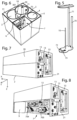
Figure 1 is a perspective view of an interface module according to the invention arranged in a first configuration; -
Figure 2 is a perspective view ofFigure 1 in which an openable door has been removed; -
Figure 3 is a perspective view ofFigure 2 in which an expansion vessel has been removed; -
Figure 4 is a perspective view of a technical tank and a storing tank comprised in the module ofFigure 1 ; -
Figure 5 is a perspective view of the technical tank ofFigure 4 in which a respective lateral surface has been removed; -
Figure 6 is a sectional view along the plane VI-VI ofFigure 1 ; -
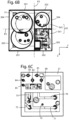
Figure 6B is a top view ofFigure 6 ; -
Figure 6C is a bottom view ofFigure 6 ; -
Figure 7 is a perspective view of a module according to the invention arranged in a second configuration; -
Figure 8 is a perspective view ofFigure 7 in which an openable door has been removed; -
Figure 9 is a perspective view of a module according to the invention arranged in a third configuration; -
Figure 10 is a perspective view ofFigure 9 in which an openable door has been removed; -
Figure 11 is a schematic representation of the components of the module ofFigure 1 . - With reference to
Figure 1 , an interface module for a hydronic system 100 (depicted inFigure 11 ) is indicated as a whole by 1. With reference toFigure 11 , thesystem 100 comprises ahydronic generator 101, at least oneclimate control device 102, at least one sanitarywater dispensing device 104 and at least onewater network connection 103. In detail, thehydronic generator 101 consists of any thermal generator that uses water or an aqueous solution as a circulating work fluid, and preferably consists of an air-water or water-water heat pump, but it can also consist of a generic boiler. Theclimate control device 102, instead, consists of any device configured to heat or cool the air in the room in which it is placed, and therefore can consist, for example, of a radiant system, a fan heater or a fan coil. Finally, the sanitarywater dispensing device 104 consists of any device that can dispense sanitary hot water, such as those commonly placed in bathrooms and kitchens of homes. - Still with reference to
Figure 1 , themodule 1 comprises acasing 2 that defines internally a chamber. Preferably, the chamber has the shape of a substantially rectangular parallelepiped and is delimited by afirst base 21 and asecond base 20 that are opposed to each other along a first direction X and by fourlateral faces bases lateral faces - With reference to
Figure 6B , the chamber is separated in a first volume V1 and a second volume V2 by a second imaginary plane P2 perpendicular to the second direction Y and that divides each of the depth edges in afirst portion 201 and asecond portion 202. The second volume V2 is in turn separated in a first sub-volume SV1 and a second sub-volume SV2 by a third imaginary plane P3 perpendicular to the third direction Z and that divides each of the width edges in afirst segment 203 and asecond segment 204. - At the first sub-volume SV1, the lateral faces of the
casing 2 have an openable door 26 (visible inFigure 1 ), which allows access to the components housed in the first sub-volume SV1 for possible maintenance operations. Following a careful study conducted by the applicant, it has been observed that themodule 1 has particularly compact overall dimensions if the various dimensions of the edges, portions and segments meet the following proportions: - the depth edges have a first length,
- the width edges have a second length that is greater than the four fifths of the first length and less than the six fifths of the first length,
- the height edges have a third length that is greater than twice the first length and less than three times the first length,
- the first portion has a fourth length,
- the second portion has a fifth length that is less than the fourth length and greater than one third of the fourth length,
- the first segment has a sixth length,
- the second segment has a seventh length that is less than the sixth length and greater than one third of the sixth length.
- The first volume V1 is thus larger than the second volume V2, and the first sub-volume SV1 is larger than the second sub-volume SV2.
- The
module 1 is therefore scalable, i.e., it can be formed with overall dimensions that differ depending on the needs (dimensions of the rooms served, number of sanitary water dispensing devices), preferably meeting the proportions described above. - Furthermore, the study conducted by the applicant has allowed to identify dimensions of the edges, portions and segments that are particularly advantageous in the case where the rooms served have a surface not greater than 120 square meters, have at most two bathrooms, and are inhabited by a maximum of four people:
- the first length is comprised between 40 cm and 60 cm, preferably 51 cm,
- the second length is comprised between 40 cm and 60 cm, preferably 47 cm,
- the third length is comprised between 100 cm and 150 cm, preferably 135 cm,
- the fourth length is comprised between 25 cm and 35 cm, preferably 30 cm,
- the sixth length is comprised between 25 cm and 35 cm, preferably 30 cm.
- With reference to
Figure 4 , themodule 1 comprises atechnical tank 3 and astoring tank 4 housed in the chamber and placed in such a way as the first sub-volume SV1 remains defined at least partially between themselves. - More particularly, the
storing tank 4 and thetechnical tank 3 have a shape that is elongated along the first direction X, and are placed in such a way as to define respectively a first arm and a second arm that extend respectively along the second direction Y and the third direction Z, thus forming an L-shape on a first imaginary plane P1 (depicted inFigure 1 ) perpendicular to the first direction X. Thereby, the first sub-volume SV1 remains defined between the first arm and the second arm, i.e., it remains identified on the first imaginary plane P1 by the convex portion of the plane delimited by the first arm and the second arm. - Preferably, the
technical tank 3 is housed in the first volume V1, while thestoring tank 4 is housed in the second sub-volume SV2. - In detail, the
technical tank 3 is formed by a firstcylindrical portion 30 and a secondcylindrical portion 31 that extend along the first direction X, that are partially meshed so as to be communicating with each other and are placed beside along the third direction Z thus defining the second arm of the L-shape. More particularly, the firstcylindrical portion 30 is formed by a cylindrical tank that extends along the first direction X and defines a first space inside itself, while the secondcylindrical portion 31 is formed by a curved and closed at the ends sheet that extends along the first direction X, being placed beside and externally joined to the cylindrical tank in such a way as to define a second space inside itself: the cylindrical tank further has at least one opening 301 (visible inFigure 6 ) that puts the first space in fluid-dynamical communication with the second space, allowing the free movement of the work fluid between the first space and the second space. Preferably, the cylindrical tank has a plurality ofopenings 301 that put the first space in fluid-dynamical communication with the second space, which are aligned along the portion of the cylindrical tank to which the curved sheet is joined. - It has been observed that this particular configuration of the
technical tank 3 allows a particularly efficient stratification of the work fluid contained therein depending on the temperature. - In a non-illustrated embodiment, the technical tank also comprises a third cylindrical portion that extends along the first direction and that is partially meshed with the second cylindrical portion, so as to be communicating with it and substantially aligned with the first cylindrical portion and the second cylindrical portion along the third direction.
- Preferably, the
storing tank 4 has a cylindrical shape. The study conducted by the applicant has also allowed to identify capacities of thetechnical tank 3 and thestoring tank 4 that are particularly advantageous in the case where the rooms served have a surface not greater than 120 square meters, have at most two bathrooms, and are inhabited by a maximum of four people: - the
technical tank 3 has a capacity comprised between 80 litres and 120 litres, preferably 105 litres, - the
storing tank 4 has a capacity comprised between 20 litres and 30 litres, preferably 27 litres. - Still with reference to
Figure 4 , themodule 1 further comprises a plurality of brackets 11 (preferably four in number and fixed to the technical tank 3) configured to anchor thetechnical tank 3 to thecasing 2 and to supports (not illustrated) employed for wall mounting themodule 1. - Again with reference to
Figure 6 , themodule 1 also comprises thermal insulation means 5 configured to thermally insulate thetechnical tank 3 and thestoring tank 4. In particular, the thermal insulation means 5 consist of rigid polyurethane foam shaped in such a way as to entirely surround thetechnical tank 3 and thestoring tank 4, joining them into a single L-shaped block: the foam fills the portions of the first volume V1 and the second sub-volume SV2 that are not occupied by thetechnical tank 3 or thestoring tank 4, so that there is everywhere a layer of foam at least 2.5 cm thick between thetechnical tank 3 or thestoring tank 4 and the lateral faces 22, 23, 24, 25 of thecasing 2. - With reference to
Figures 2 and 3 , themodule 1 further comprises aheat exchanger 6 and a network ofhydraulic connections 7 that are housed at least partially in the first sub-volume SV1 and configured to fluid-dynamically connect together thetechnical tank 3, thestoring tank 4, and theheat exchanger 6. - In particular,
heat exchanger 6 allows to produce sanitary hot water by heating the network water from theconnection 103 by means of the hot work fluid contained in thetechnical tank 3 and sending it towards the sanitarywater dispensing device 104. - With reference to
Figure 6C , the network further comprises afirst inlet 80 and afirst outlet 81 configured to be fluid-dynamically connected to thehydronic generator 101, asecond inlet 82 and asecond outlet 83 configured to be fluid-dynamically connected to theclimate control device 102, athird inlet 84 configured to be fluid-dynamically connected to thewater network connection 103, and athird outlet 85 configured to be fluid-dynamically connected to the sanitarywater dispensing device 104. - Preferably, the
inlets outlets first base 21. - In the illustrated embodiment, the
heat exchanger 6 comprises anexchanger module 6 housed in the first sub-volume SV1. - With reference to
Figure 11 , the network particularly comprises: - a first
hydraulic connection 70 configured to fluid-dynamically connect thefirst inlet 80 to thetechnical tank 3; - a second
hydraulic connection 71 and a thirdhydraulic connection 72 respectively configured to fluid-dynamically connect thetechnical tank 3 to theexchanger module 6 and vice versa; - a fourth
hydraulic connection 73 configured to fluid-dynamically connect thetechnical tank 3 to thefirst outlet 81; - a fifth
hydraulic connection 74 configured to fluid-dynamically connect thefirst inlet 80 to storingtank 4; - a sixth
hydraulic connection 75 configured to fluid-dynamically connectstoring tank 4 to thesecond outlet 83; - a seventh
hydraulic connection 76 configured to fluid-dynamically connect thesecond inlet 82 to storingtank 4; - an eighth
hydraulic connection 77 configured to fluid-dynamically connect thestoring tank 4 to thefirst outlet 81; - a ninth
hydraulic connection 78 configured to fluid-dynamically connect thethird inlet 84 to theexchanger module 6; - a tenth
hydraulic connection 79 configured to fluid-dynamically connect theexchanger module 6 to thethird outlet 85. - Preferably, the first
hydraulic connection 70 and the fifthhydraulic connection 74 comprise a firstcommon section 705 that extends from thefirst inlet 80 and ends with a deviatingvalve 706 housed in the first sub-volume SV1 and controllable to allow the flow of the work fluid from thehydronic generator 101 alternatively towards thetechnical tank 3 or thestoring tank 4. Thereby, a dynamical separation is formed between a first hydraulic circuit for climatically controlling the rooms and a second hydraulic circuit for producing sanitary hot water. - Preferably, a
minimum temperature valve 707 is housed in the first sub-volume SV1 along the firsthydraulic connection 70, and is configured to prevent the flow of the work fluid from thehydronic generator 101 towards thetechnical tank 3 if the temperature of the work fluid is less than a threshold temperature value: if the temperature of the work fluid is less than the threshold temperature value, the work fluid is deviated towards thefirst outlet 81 along a twelfthhydraulic connection 709. Preferably, the threshold temperature value is comprised between 40°C and 50°C, particularly 45°C. Furthermore, the network preferably also comprises an eleventhhydraulic connection 701 configured to fluid-dynamically connect thethird inlet 84 to the second outlet 83: afill tap 702, operable to selectively allow or prevent a flow of water from the water network along the eleventhhydraulic connection 701, is preferably placed along such eleventhhydraulic connection 701. Preferably, all thehydraulic connections 7 consist of insulated pipelines. - The network further comprises pumping means housed in the first sub-volume SV1 and configured to move the work fluid along the
hydraulic connections 7, i.e., in particular, to selectively activate the circulation of the work fluid along thehydraulic connections 7 themselves. In particular, the pumping means preferably comprise afirst pump 703 configured to move the work fluid from thetechnical tank 3 towards theexchanger module 6 along the secondhydraulic connection 71, and asecond pump 704 configured to move the work fluid from thestoring tank 4 to thesecond outlet 83, i.e., towards theclimate control device 102, along the sixthhydraulic connection 75. - Preferably, the
first pump 703 and thesecond pump 704 consist of centrifugal pumps. - Preferably, the fifth
hydraulic connection 74 and the sixthhydraulic connection 75 have a secondcommon section 711 in which the work fluid can alternatively flow in both directions, depending on the activation of the deviatingvalve 706 and thesecond pump 704. Preferably, themodule 1 further comprises a flow switch 708 placed along the ninth hydraulic connection 78: it is configured to detect a flow of network water along the ninthhydraulic connection 78 and to consequently operate thefirst pump 703. - The
module 1 further comprises afirst expansion vessel 9 fluid-dynamically connected to the sixthhydraulic connection 75 by a thirteenthhydraulic connection 710. Preferably, thefirst expansion vessel 9 consists of a membrane vessel and preferably has a capacity of 10 litres. Themodule 1 can further comprise a second expansion vessel (not illustrated) fluid-dynamically connected to the ninthhydraulic connection 78 and provided with a specific safety valve. - With reference to
Figures 5 and 6 , the firsthydraulic connection 70 and the secondhydraulic connection 71 enter thetechnical tank 3 through the lower base thereof and also extend inside it along the first direction X. Alternatively, the firsthydraulic connection 70 and the secondhydraulic connection 71 can enter thetechnical tank 3 through a flank thereof, for example in proximity to the upper base thereof. - Furthermore, the
technical tank 3 has a well 10 configured to house a temperature probe configured to control the temperature of the work fluid contained in thetechnical tank 3. - In non-illustrated embodiments, the module can also comprise two hydrometers for detecting the level of work fluid in the technical tank and the storing tank, respectively, and/or a system for regulating the temperature of the sanitary hot water exiting the heat exchanger.
- Furthermore, the
module 1 can also comprise an electric heater (not illustrated) arranged along the firstcommon section 705 to assist the hydronic generator in producing sanitary hot water and heating the rooms. Alternatively, themodule 1 can comprise two separate electric heaters to assist the hydronic generator in producing sanitary hot water and heating the rooms. - In a non-illustrated embodiment, the
heat exchanger 6, instead of comprising an exchanger module housed in the first sub-volume SV1, comprises an exchange conduit placed inside thetechnical tank 3. The exchange conduit has an inlet mouth fluid-dynamically connected to thethird inlet 84 by a first alternative hydraulic connection, and an outlet mouth fluid-dynamically connected to thethird outlet 85 by a second alternative hydraulic connection. In such case, the network water from theconnection 103 is heated by the heat flowing through the wall of the exchange conduit and coming from the hot work fluid contained in thetechnical tank 3. The exchange conduit preferably has a coil shape, in order to increase the thermal exchange surface. - In this embodiment, the first alternative hydraulic connection and the second alternative hydraulic connection replace the second
hydraulic connection 71, the thirdhydraulic connection 72, the ninthhydraulic connection 78, and the tenthhydraulic connection 79. Furthermore, in such embodiment, the pumping means do not comprise thefirst pump 703, and themodule 1 does not comprise the flow switch 708 and the second expansion vessel. In any other aspect, such embodiment is similar in components and operation to the embodiment described above and illustrated. - A further non-illustrated embodiment, combinable with other non-illustrated embodiments, is more advantageous in the case where the rooms served have a surface greater than 120 square meters, have more than two bathrooms, and/or are inhabited by more than four people. In this embodiment:
- the first length measures 55 cm;
- the second length measures 54 cm;
- the third length measures 140 cm;
- the fourth length measures 33 cm;
- the sixth length measures 33 cm;
- the
technical tank 3 has a capacity of 150 litres; - the
storing tank 4 has a capacity of 35 litres. - In any other aspect, such embodiment is similar in components and operation to the embodiment described above and illustrated.
- With reference to
Figures 1 to 6C , themodule 1 can be arranged in a first configuration in which the first direction X is substantially parallel to the vertical direction, i.e., the direction along which gravity acts. In such case, themodule 1 comprises a plurality of first vent valves 12 (visible inFigures 1, 2, and 3 ) configured to allow a venting of air from thetechnical tank 3, thestoring tank 4, and thehydraulic connections 7. - In this first configuration, the
module 1 can be placed, for example, in a standard kitchen module or a standard boiler chamber. - With reference to
Figures 7 and 8 , themodule 1 can be arranged in a second configuration in which the first direction X is substantially perpendicular to the vertical direction. In such case, themodule 1 comprises a plurality ofsecond vent valves 13 configured to allow a venting of air from thetechnical tank 3, thestoring tank 4, and thehydraulic connections 7. As for the remaining components of themodule 1, they are identical in the first and second configurations: therefore, in order to install amodule 1 in the second configuration, it is sufficient to provide amodule 1 in the first configuration, substitute thefirst vent valves 12 with thesecond vent valves 13, and finally move themodule 1 from the vertical position to the horizontal position. In this second configuration, themodule 1 can be placed, for example, in a false ceiling. - With reference to
Figures 9 and 10 , themodule 1 can be arranged in a third configuration in which the first direction X is substantially perpendicular to the vertical direction, and in which themodule 1 is configured to rest on a floor. In such case, themodule 1 comprises a plurality ofsecond vent valves 13 similarly to themodule 1 placed in the second configuration but has an alternative casing 2' substituting thecasing 2. In particular, the alternative casing 2' has an alternative first base 21' and an alternative second base 20' shaped in such a way as to rest on twosupports module 1 can be placed under thehydronic generator 101, possibly also supporting thehydronic generator 101 itself if suitably provided with external accessories, not illustrated in the figures, such as a condensate collection tray and a support frame. - In use, by appropriately acting on the deviating
valve 706 and appropriately operating thehydronic generator 101, thefirst pump 703, and thesecond pump 704, it is possible to heat or cool the room served by theclimate control device 102, and alternatively (not simultaneously) produce sanitary hot water in the sanitarywater dispensing device 104. In particular, thehydronic generator 101 can be employed both to input hot or cold work fluid inside thestoring tank 4, which can then be employed for climatically controlling the rooms through theclimate control device 102, and to input hot work fluid inside thetechnical tank 3, which can then be employed by theheat exchanger 6 for producing sanitary hot water to be dispensed through the sanitarywater dispensing device 104. - It is therefore clear that the present invention is perfectly capable of overcoming the drawbacks of the state of the art described above. In particular, the
module 1 has overall dimensions that make it particularly compact and allow it to be integrated in the furnishings of the rooms served. Furthermore, the arrangement of the components inside themodule 1 makes it particularly flexible to use, and allows themodule 1 itself to be placed both vertically and horizontally, depending on the available spaces in the rooms served, simply by substituting thefirst vent valves 12 with thesecond vent valves 13. - Furthermore, the particular arrangement of the components inside the
module 1 allows an easy access to the components themselves through theopenable door 26, remarkably facilitating the maintenance operations of themodule 1. - Furthermore, the particular arrangement of the components inside the
module 1 allows to eliminate the need for specific support elements, such as frames and complex structures, as thetechnical tank 3 itself acts as a support for all the components. Together with the thermal insulation means 5, thetechnical tank 3 forms a monolithic structure that supports all the components and can be wall-mounted by thebrackets 11. This allows to reduce the overall weight of themodule 1, making the installation operation easier. - Furthermore, the particular arrangement of the
inlets outlets first base 21, which is allowed by the particular arrangement of the components inside themodule 1, makes the installation operation of themodule 1 particularly easy, in the first configuration, second configuration, and third configuration. - Furthermore, the particular arrangement of the components inside the
module 1 allows the installation offirst vent valves 12 orsecond vent valves 13 in particularly advantageous positions, making the venting of air from thetechnical tank 3, thestoring tank 4, and thehydraulic connections 7 particularly efficient. The present invention has been described, by way of illustration, but not limitation, according to its preferred embodiments, but it is to be understood that variations and/or modifications may be made by a person skilled in the art without departing from the related scope of protection as defined in the appended claims.
Claims (20)
- Interface module (1) for a hydronic system (100), said hydronic system (100) comprising a hydronic generator (101) that uses a work fluid, at least one climate control device (102), at least one sanitary water dispensing device (104) and at least one water network connection (103), said module (1) comprising a casing (2) that defines internally a chamber that houses:- a technical tank (3) and a storing tank (4) configured to contain said work fluid and placed in such a way as to delimit a first sub-volume (SV1) at least partially between themselves;- a heat exchanger (6);- a network of hydraulic connections (7) that are housed at least partially in said first sub-volume (SV1) and are configured to fluid-dynamically connect together said technical tank (3), said storing tank (4) and said heat exchanger (6);said network further comprising at least:- a first inlet (80) and a first outlet (81) configured to be fluid-dynamically connected, in use, to said hydronic generator (101);- a second inlet (82) and a second outlet (83) configured to be fluid-dynamically connected, in use, to said at least one climate control device (102);- a third inlet (84) and a third outlet (85) configured to be fluid-dynamically connected, in use, respectively to said connection (103) and to said at least one sanitary water dispensing device (104);- pumping means housed in said first sub-volume (SV1) and configured to move said work fluid along said hydraulic connections (7).
- Module (1) according to claim 1, characterized in that said storing tank (4) and said technical tank (3) have a shape that is elongated along a first direction (X) and are placed in such a way as to define respectively a first arm and a second arm that extend respectively along a second direction (Y) and a third direction (Z) that are substantially perpendicular to each other and substantially perpendicular to said first direction (X) so as to form an L-shape in a first imaginary plane (P1) that is perpendicular to said first direction (X), said first sub-volume (SV1) being defined between said first arm and second arm.
- Module (1) according to claim 2, characterized in that said chamber has the shape of a substantially rectangular parallelepiped delimited by a first base (21) and a second base (20) that are opposed to each other along said first direction (X) and by four lateral faces (22, 23, 24, 25) that are opposed to each other two by two respectively along said second direction (Y) and third direction (Z), said first base (21), second base (20) and lateral faces (22, 23, 24, 25) being defined by four height edges substantially parallel to said first direction (X), four depth edges substantially parallel to said second direction (Y) and four width edges substantially parallel to said third direction (Z) .
- Module (1) according to claim 3, characterized in that said chamber is separated in a first volume (V1) and a second volume (V2) by a second imaginary plane (P2) that is perpendicular to said second direction (Y) and that divides each of said depth edges in a first portion (201) and a second portion (202), said second volume (V2) being separated in said first sub-volume (SV1) and a second sub-volume (SV2) by a third imaginary plane (P3) that is perpendicular to said third direction (Z) and that divides each of said width edges in a first segment (203) and a second segment (204), said technical tank (3) being housed in said first volume (V1) and said storing tank (4) being housed in said second sub-volume (SV2) .
- Module (1) according to claim 4, characterized in that said depth edges have a first length, said width edges have a second length that is greater than the four fifths of said first length and less than the six fifths of said first length, said height edges have a third length that is greater than twice said first length and less than three times said first length, said first portion (201) has a fourth length, said second portion (202) has a fifth length that is less than said fourth length and greater than one third of said fourth length, said first segment (203) has a sixth length, said second segment (204) has a seventh length that is less than said sixth length and greater than one third of said sixth length, said first volume (V1) being larger than said second volume (V2) and said first sub-volume (SV1) being larger than said second sub-volume (SV2).
- Module (1) according to claim 5, characterized in that said first length is comprised between 40 cm and 60 cm, said second length is comprised between 40 cm and 60 cm, said third length is comprised between 100 cm and 150 cm, said fourth length is comprised between 25 cm and 35 cm and said sixth length is comprised between 25 cm and 35 cm.
- Module (1) according to claim 6, characterized in that said technical tank (3) has a capacity comprised between 80 litres and 120 litres and said storing tank (4) has a capacity comprised between 20 litres and 30 litres.
- Module (1) according to claim 6, characterized in that said technical tank (3) has a capacity comprised between 140 litres and 160 litres and said storing tank (4) has a capacity comprised between 30 litres and 40 litres.
- Module (1) according to any of claims 2 to 8, characterized in that said technical tank (3) is formed by at least a first cylindrical portion (30) and a second cylindrical portion (31) that extend along said first direction (X), that are partially meshed and communicating with each other and that are aligned substantially parallel to said third direction (Z).
- Module (1) according to claim 9, characterized in that said technical tank (3) comprises a cylindrical tank that extends along said first direction (X) forming said first cylindrical portion (30) and defining a first space inside itself, and a curved and closed at the ends sheet that extends along said first direction (X) and is placed beside and externally joined to said cylindrical tank forming said second cylindrical portion (31) and defining a second space inside itself, said cylindrical tank having at least an opening (301) that puts said first space in fluid-dynamical communication with said second space.
- Module (1) according to any of the preceding claims, characterized in that it comprises thermal insulation means (5) configured to thermally insulate said technical tank (3) and said storing tank (4).
- Module (1) according to any of the preceding claims, characterized in that said pumping means comprise a second pump (704) configured to move said work fluid from said storing tank (4) towards said at least one climate control device (102).
- Module (1) according to any of the preceding claims, characterized in that said heat exchanger (6) comprises an exchanger module (6) housed inside said first sub-volume (SV1), said pumping means comprising a first pump (703) configured to move said work fluid from said technical tank (3) towards said exchanger module (6).
- Module (1) according to any of claims 1 to 12, characterized in that said heat exchanger (6) comprises an exchange conduit placed inside said technical tank (3) and having an inlet mouth fluid-dynamically connected to said third inlet (84) and an outlet mouth fluid-dynamically connected to said third outlet (85).
- Module (1) according to any of the preceding claims, characterized in that it comprises a deviating valve (706) housed in said first sub-volume (SV1) and configured to allow a flow of said work fluid from said hydronic generator (101) alternatively towards said technical tank (3) or said storing tank (4).
- Module (1) according to any of the preceding claims, characterized in that it comprises a minimum temperature valve (707) housed in said first sub-volume (SV1) and configured to prevent a flow of said work fluid from said hydronic generator (101) towards said technical tank (3) if a temperature value of said work fluid is less than a threshold temperature value.
- Module (1) according to claim 1, characterized in that said casing (2) comprises a first base (21) and a second base (20) opposed to each other along a first direction (X), said technical tank (3), said storing tank (4) and said first sub-volume (SV1) being placed between said first base (21) and second base (20), said inlets (80, 82, 84) and said outlets (81, 83, 85) being placed on said first base (21).
- Module (1) according to any of the preceding claims, characterized in that it comprises a plurality of first vent valves (12) configured to allow a venting of air from said technical tank (3) and/or from said storing tank (4) and/or from said hydraulic connections (7) when said module (1) is arranged in a first configuration in which said first direction (X) is substantially parallel to a vertical direction.
- Module (1) according to any of the claims 1 to 17, characterized in that it comprises a plurality of second vent valves (13) configured to allow a venting of air from said technical tank (3) and/or from said storing tank (4) and/or from said hydraulic connections (7) when said module (1) is arranged in a second configuration in which said first direction (X) is substantially perpendicular to a vertical direction.
- Method for installing a module (1) according to claim 19, comprising the following steps:- provide a module (1) according to claim 18;- substituting said first vent valves (12) with said second vent valves (13);- move said module (1) from said first configuration to said second configuration.
Applications Claiming Priority (1)
| Application Number | Priority Date | Filing Date | Title |
|---|---|---|---|
| IT102023000017601A IT202300017601A1 (en) | 2023-08-25 | 2023-08-25 | INTERFACE MODULE FOR A HYDRONIC SYSTEM. |
Publications (3)
| Publication Number | Publication Date |
|---|---|
| EP4513102A1 true EP4513102A1 (en) | 2025-02-26 |
| EP4513102B1 EP4513102B1 (en) | 2025-12-03 |
| EP4513102C0 EP4513102C0 (en) | 2025-12-03 |
Family
ID=88690069
Family Applications (1)
| Application Number | Title | Priority Date | Filing Date |
|---|---|---|---|
| EP24196052.5A Active EP4513102B1 (en) | 2023-08-25 | 2024-08-23 | Interface module for a hydronic system |
Country Status (2)
| Country | Link |
|---|---|
| EP (1) | EP4513102B1 (en) |
| IT (1) | IT202300017601A1 (en) |
Citations (4)
| Publication number | Priority date | Publication date | Assignee | Title |
|---|---|---|---|---|
| GB2332737A (en) * | 1997-12-17 | 1999-06-30 | Gledhill Water Storage | Organisation of water heating systems |
| DE10326262A1 (en) * | 2003-06-11 | 2005-01-13 | Robert Bosch Gmbh | Heating appliance for water heating and space heating consists of connected tank and heating modules, one mounted in front of other, and fixed to wall |
| EP2453179A1 (en) * | 2010-11-15 | 2012-05-16 | Roth Werke GmbH | Modular warm water system |
| DE202015001818U1 (en) * | 2015-03-10 | 2016-06-13 | Stiebel Eltron Gmbh & Co. Kg | Hot water tank with two tanks |
-
2023
- 2023-08-25 IT IT102023000017601A patent/IT202300017601A1/en unknown
-
2024
- 2024-08-23 EP EP24196052.5A patent/EP4513102B1/en active Active
Patent Citations (4)
| Publication number | Priority date | Publication date | Assignee | Title |
|---|---|---|---|---|
| GB2332737A (en) * | 1997-12-17 | 1999-06-30 | Gledhill Water Storage | Organisation of water heating systems |
| DE10326262A1 (en) * | 2003-06-11 | 2005-01-13 | Robert Bosch Gmbh | Heating appliance for water heating and space heating consists of connected tank and heating modules, one mounted in front of other, and fixed to wall |
| EP2453179A1 (en) * | 2010-11-15 | 2012-05-16 | Roth Werke GmbH | Modular warm water system |
| DE202015001818U1 (en) * | 2015-03-10 | 2016-06-13 | Stiebel Eltron Gmbh & Co. Kg | Hot water tank with two tanks |
Also Published As
| Publication number | Publication date |
|---|---|
| EP4513102B1 (en) | 2025-12-03 |
| EP4513102C0 (en) | 2025-12-03 |
| IT202300017601A1 (en) | 2025-02-25 |
Similar Documents
| Publication | Publication Date | Title |
|---|---|---|
| EP3839360B1 (en) | Heat pump and method for installing the same | |
| US20220146147A1 (en) | Air heating and potable water system having a water heater and a hydronic air handler | |
| US7277627B2 (en) | Rooftop water heater | |
| EP2031333A2 (en) | Improved accumulation reservoir for fluids | |
| JP4743008B2 (en) | Heat pump type water heater | |
| US12607415B2 (en) | Modular, stackable PCM-based thermal battery apparatus | |
| EP4513102B1 (en) | Interface module for a hydronic system | |
| JP2005098628A (en) | Heat source water supply system | |
| EP4521026A1 (en) | Water heating system containing a non-pressurized heat accumulator, building wall containing said non-pressurized heat accumulator and water heating method using said water heating system | |
| EP3924669A1 (en) | Electric boiler, central heating system comprising an electric boiler, tap water heating system comprising an electric boiler and method for operating the same | |
| JP7294203B2 (en) | Hot water storage type water heater and its installation method | |
| CN210135635U (en) | Auxiliary heating system | |
| JP2008304088A (en) | Heat pump hot water storage system | |
| CN216897478U (en) | Full-automatic unattended heat exchanger unit | |
| GB2050704A (en) | Control apparatus | |
| CA3226417A1 (en) | Outdoor energy-storage device | |
| EP4491952B1 (en) | Outdoor unit of air conditioner | |
| EP4636321A1 (en) | Connecting assembly for a heat control system | |
| JP7526694B2 (en) | Hot water supply equipment | |
| KR100930707B1 (en) | Heating device and hot water supply device using cyclone type heat generating means and auxiliary heater | |
| JP4762298B2 (en) | Electric hot water circulation floor heating system | |
| WO2025126035A1 (en) | A hot water provisioning system | |
| WO2026088094A1 (en) | A hot water supply system | |
| IT202200005451U1 (en) | Domestic hot water heating system or liquid for thermo heating | |
| ITMI20090527A1 (en) | HYDRAULIC CONNECTION MODULE FOR THE THERMAL UTILITIES OF A BIVALENT AIR-CONDITIONING PLANT AND AIR-CONDITIONING SYSTEM INCLUDING SUCH MODULE |
Legal Events
| Date | Code | Title | Description |
|---|---|---|---|
| PUAI | Public reference made under article 153(3) epc to a published international application that has entered the european phase |
Free format text: ORIGINAL CODE: 0009012 |
|
| STAA | Information on the status of an ep patent application or granted ep patent |
Free format text: STATUS: THE APPLICATION HAS BEEN PUBLISHED |
|
| AK | Designated contracting states |
Kind code of ref document: A1 Designated state(s): AL AT BE BG CH CY CZ DE DK EE ES FI FR GB GR HR HU IE IS IT LI LT LU LV MC ME MK MT NL NO PL PT RO RS SE SI SK SM TR |
|
| STAA | Information on the status of an ep patent application or granted ep patent |
Free format text: STATUS: REQUEST FOR EXAMINATION WAS MADE |
|
| 17P | Request for examination filed |
Effective date: 20250805 |
|
| GRAP | Despatch of communication of intention to grant a patent |
Free format text: ORIGINAL CODE: EPIDOSNIGR1 |
|
| STAA | Information on the status of an ep patent application or granted ep patent |
Free format text: STATUS: GRANT OF PATENT IS INTENDED |
|
| GRAS | Grant fee paid |
Free format text: ORIGINAL CODE: EPIDOSNIGR3 |
|
| INTG | Intention to grant announced |
Effective date: 20250926 |
|
| GRAA | (expected) grant |
Free format text: ORIGINAL CODE: 0009210 |
|
| STAA | Information on the status of an ep patent application or granted ep patent |
Free format text: STATUS: THE PATENT HAS BEEN GRANTED |
|
| AK | Designated contracting states |
Kind code of ref document: B1 Designated state(s): AL AT BE BG CH CY CZ DE DK EE ES FI FR GB GR HR HU IE IS IT LI LT LU LV MC ME MK MT NL NO PL PT RO RS SE SI SK SM TR |
|
| REG | Reference to a national code |
Ref country code: CH Ref legal event code: F10 Free format text: ST27 STATUS EVENT CODE: U-0-0-F10-F00 (AS PROVIDED BY THE NATIONAL OFFICE) Effective date: 20251203 Ref country code: GB Ref legal event code: FG4D |
|
| REG | Reference to a national code |
Ref country code: DE Ref legal event code: R096 Ref document number: 602024001519 Country of ref document: DE |
|
| REG | Reference to a national code |
Ref country code: IE Ref legal event code: FG4D |
|
| U01 | Request for unitary effect filed |
Effective date: 20251211 |
|
| U07 | Unitary effect registered |
Designated state(s): AT BE BG DE DK EE FI FR IT LT LU LV MT NL PT RO SE SI Effective date: 20251217 |
|
| REG | Reference to a national code |
Ref country code: CH Ref legal event code: R17 Free format text: ST27 STATUS EVENT CODE: U-0-0-R10-R17 (AS PROVIDED BY THE NATIONAL OFFICE) Effective date: 20260227 |
|
| U1N | Appointed representative for the unitary patent procedure changed after the registration of the unitary effect |
Representative=s name: CANTALUPPI, STEFANO; IT |
|
| PG25 | Lapsed in a contracting state [announced via postgrant information from national office to epo] |
Ref country code: NO Free format text: LAPSE BECAUSE OF FAILURE TO SUBMIT A TRANSLATION OF THE DESCRIPTION OR TO PAY THE FEE WITHIN THE PRESCRIBED TIME-LIMIT Effective date: 20260303 |
|
| PG25 | Lapsed in a contracting state [announced via postgrant information from national office to epo] |
Ref country code: HR Free format text: LAPSE BECAUSE OF FAILURE TO SUBMIT A TRANSLATION OF THE DESCRIPTION OR TO PAY THE FEE WITHIN THE PRESCRIBED TIME-LIMIT Effective date: 20251203 |
|
| PG25 | Lapsed in a contracting state [announced via postgrant information from national office to epo] |
Ref country code: RS Free format text: LAPSE BECAUSE OF FAILURE TO SUBMIT A TRANSLATION OF THE DESCRIPTION OR TO PAY THE FEE WITHIN THE PRESCRIBED TIME-LIMIT Effective date: 20260303 |
|
| PG25 | Lapsed in a contracting state [announced via postgrant information from national office to epo] |
Ref country code: PL Free format text: LAPSE BECAUSE OF FAILURE TO SUBMIT A TRANSLATION OF THE DESCRIPTION OR TO PAY THE FEE WITHIN THE PRESCRIBED TIME-LIMIT Effective date: 20251203 |